Embed Size (px)
Citation preview
AD-3CS |07
•
!
: I
i •
li i> M :•
II II'1
D^^?'9^^
C075
TECHNICAL L LIBRARY
.MI
MEMORANDUM REPORT NO. II80 DECEMBER 1958
DRAG AND STABILITY PROPERTIES OF
THE IOSMM SHELL, HE, T388 (U)
EUGENE D. BOYER
degraded
By authority of ftl/JLjftQ 3aS~/n~7 Date IzL&teL
DEPARTMENT OF THE ARMY PROJECT NO. SB03-03-00I
ORDNANCE RESEARCH AND DEVELOPMENT PROJECT NO. TB3"OI08
BALLISTIC RESEARCH LABORATORIES , Jni^M'r :i'n.iiiLnVifii|T li^lrjM^^iiT./jfl i'J: Hjfi* ii. L ':" n'.f^ •.>•>:•'• JM""^'' '^''^•Vyftauwns.'V.'Ji jj"1«ii.' J"> I.JM'M'.JI' 'infih""! iijt> i,i""."i ••!>(• 1111^ . 1 -jr •••> 1 ijijt
ABERDEEN PROVING GROUND, MARYLAND
7

Retain or destroy per AR 380-5 and AR 345-220, or compar- able Navy or AF Regulations. Contractors should consult their government contracting offices regarding procedures to be followed. DO NOT RETURN
,r
This document contains information affecting the national defense of the United States within the meaning of the Espionage Laws, Title 18 U. S. C. Sections 793 and 794. The transmission or the revelation of its contents in any manner to an unauthorized person is prohibited by law.
MIS REPORT HAS BEEN DELIMITED
AND CLEARED FOR PUBLIC RELEASE
UNDER DOD DIRECTIVE 5200,20 AMD
NO RESTRICTIONS ARE IMPOSED UPQU
ITS USE AND DISCLOSURE,
DISTRIBUTION STATEMENT A
APPROVED FOR PUBLIC RELEASE;
DISTRIBUTI ON UNLIMITED,
'(W*1lWW«*sV«*lt \K?,ni'*rviw^*pVn*V)n
M «f--V
5V 9 *7
C-£37-l

BALLISTIC RESEARCH LABORATORIES
MEMORANDUM REPORT NO. Il80
DECEMBER I958
DRAG AND STABILITY PROPERTIES OF THE 105MM SHELL, HE, T588 (u)
Eugene D. Boyer
Reguests for additional copies of this report will be made direct to ASTIA.
Reproduction of this document in whole or in part is prohibited except with permission of the issuing office; however, ASTIA is authorized to reproduce this document for U. S. Government purposes.
Department of the Army Project No. 5BO3-O3-OOI Ordnance Research and Development Project No. TB3-OIO8
ABERDEEN PROVING GROUND, MARYLAND

**

BALLISTIC RESEARCH LABORATORIES
MEMORANDUM REPORT NO. Il80
EDBoyer/sec Aberdeen Proving Ground, Md. December 1958
DRAG AND STABILITY PROPERTIES OF THE 105-MM SHELL, HE, T588 (U)
(UNCLASSIFIED) ABSTRACT
The drag and stability properties of the 105-mm, HE, T388 shell are
presented. These data were obtained from Transonic Range firings.

f
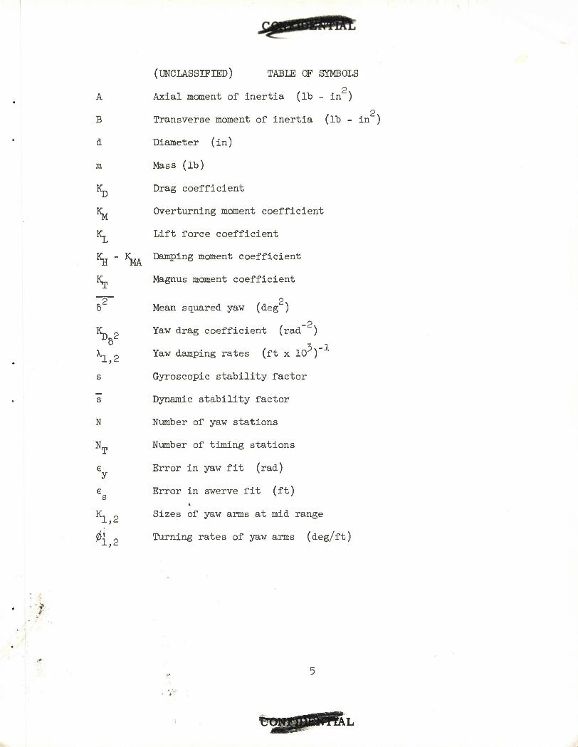
(UNCLASSIFIED) TABLE OF SYMBOLS
A Axial moment of inertia (lb - in )
2 B Transverse moment of inertia (lb - in )
d Diameter (in)
m Mass (lb)
IC Drag coefficient
K^ Overturning moment coefficient
K_ Lift force coefficient
K-j - K^ Damping moment coefficient
K„ Magnus moment coefficient
2 2 6 Mean squared yaw (deg )
_2 K^ 2 Yaw drag coefficient (rad )
6 3-1 A,, „ Yaw damping rates (ft x 10 )
s Gyroscopic stability factor
s Dynamic stability factor
N Number of yaw stations
N-, Number of timing stations
e Error in yaw fit (rad)
e Error in swerve fit (ft) s v '
K, 9 Sizes of yaw arms at mid range •*->'-
0' 0 Turning rates of yaw arms (deg/ft)

'
... - - ,

(CM—BBBft) INTRODUCTION
At the request of the Canadian Armament Research and Development
Establishment (CARDE), BRL fired, through the Transonic Range , four
versions of the 105-mm, HE, T388 shell, designed at CARDE (Figure l).
The four types varied only in body length and were designed to bracket
a stability factor of 1.8 at M = 1.1. These firings were suggested by the
Bi-partite Standardization Committee as a part of the development of improved
105-mm howitzer ammunition. The firings were to determine the drag properties
of these shell from M =0.6 to M =1.5 and the gyroscopic stability factors
at M = 1.1.
Early tests indicated that the drag of these shell was approximately 2 5
20$ lower than that of the standard Ml shell ' . The T388 shell has a long
hollow boattail and it was thought that the drag could be further reduced by
bleeding air into the base from the body of the shell. Three shell of each
type were available for stability firings at M = 1.1, and an additional ten
shell of Type 1 for base-bleed experiments.
The shell were launched from a 105-mm howitzer (l - 20 twist). A yaw
inducer was employed on the six rounds at M = 1.1. This was done in order
to obtain adequate yaw levels for a yaw reduction. The physical properties
of the shell are given in Figure 1.
PWnillirT ^ STABILITY
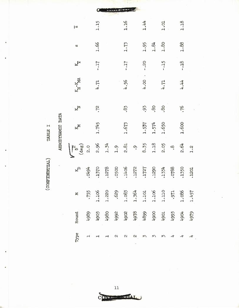
The stability factors and other aerodynamic properties of the shell are
given in Table I. The reduction parameters are given in Table II. The
stability factors, as determined at ^65 feet from the muzzle, at about M = 1.1,
vary from 1.66 for Type 1 to 1.95 for Type 2. All types are dynamically
stable at the velocity tested, M = 1.1. No yaw analysis was made at other
velocities fired. The yaw damping rates appear to be sensitive to yaw level
but the evidence, on this small sample, is rather weak.
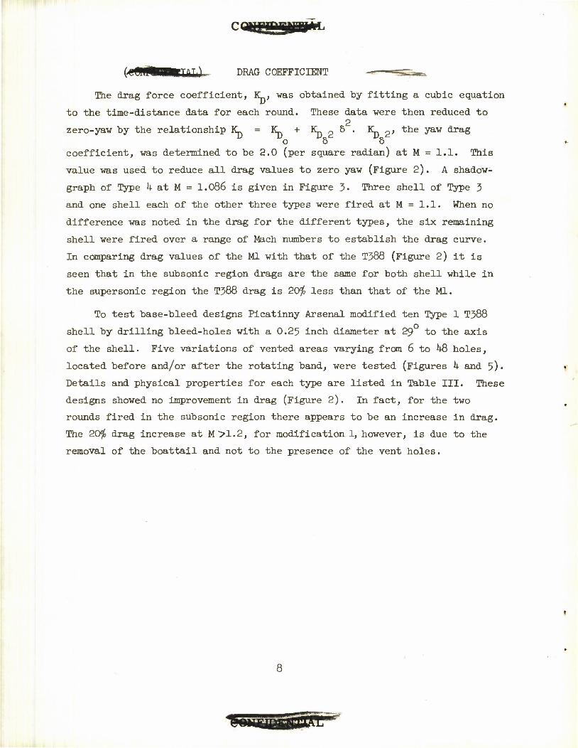
(t DRAG COEFFICIENT
The drag force coefficient, IC, was obtained by fitting a cubic equation
to the time-distance data for each round. These data were then reduced to 2
zero-yaw by the relationship IC = IC + Krj p 5 • \\ 2' the yaw ^T&^ o 5 5
coefficient, was determined to be 2.0 (per square radian) at M = 1.1. This
value was used to reduce all drag values to zero yaw (Figure 2). A shadow-
graph of Type h at M = 1.086 is given in Figure 3- Three shell of Type 3
and one shell each of the other three types were fired at M = 1.1. When no
difference was noted in the drag for the different types, the six remaining
shell were fired over a range of Mach numbers to establish the drag curve.
In comparing drag values of the Ml with that of the T388 (Figure 2) it is
seen that in the subsonic region drags are the same for both shell while in
the supersonic region the T388 drag is 20$ less than that of the Ml.
To test base-bleed designs Picatinny Arsenal modified ten Type 1 T388
shell by drilling bleed-holes with a 0.25 inch diameter at 29 to the axis
of the shell. Five variations of vented areas varying from 6 to 48 holes,
located before and/or after the rotating band, were tested (Figures k and 5)«
Details and physical properties for each type are listed in Table III. These
designs showed no improvement in drag (Figure 2). In fact, for the two
rounds fired in the subsonic region there appears to be an increase in drag.
The 20$ drag increase at M>1.2, for modification 1, however, is due to the
removal of the boattail and not to the presence of the vent holes.
8
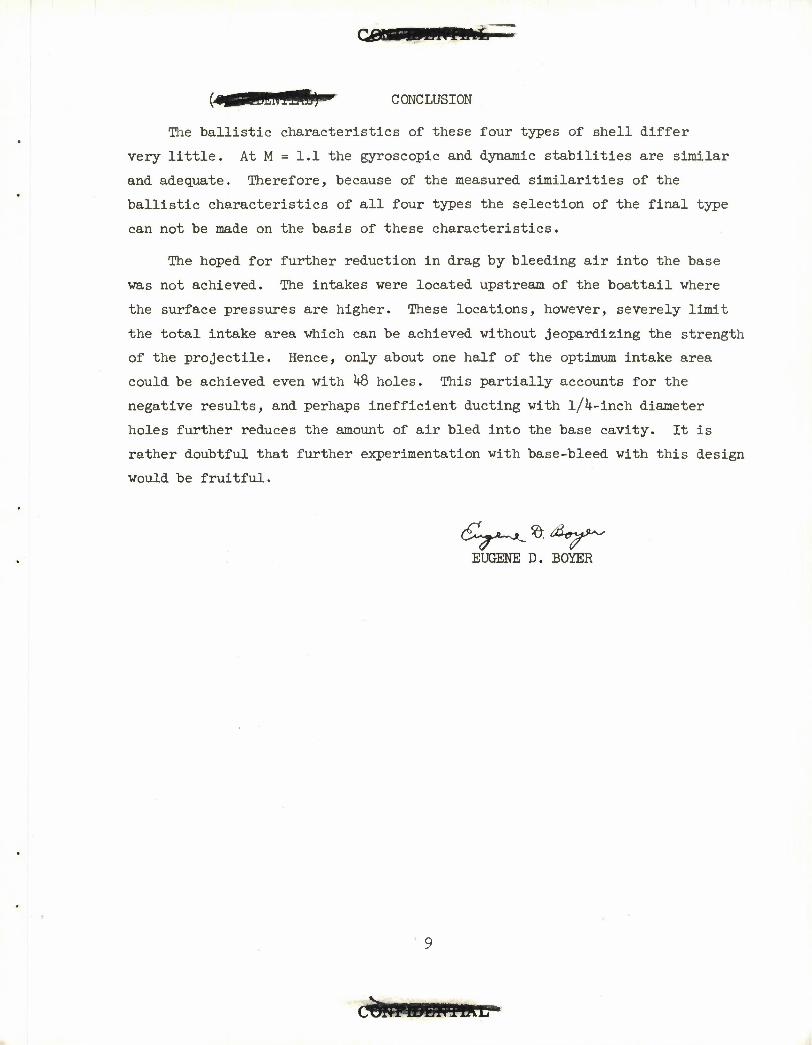
(4V0BRfflB9"»' CONCLUSION
The ballistic characteristics of these four types of shell differ
very little. At M = 1.1 the gyroscopic and dynamic stabilities are similar
and adequate. Therefore, because of the measured similarities of the
ballistic characteristics of all four types the selection of the final type
can not be made on the basis of these characteristics.
The hoped for further reduction in drag by bleeding air into the base
was not achieved. The intakes were located upstream of the boattail where
the surface pressures are higher. These locations, however, severely limit
the total intake area which can be achieved without jeopardizing the strength
of the projectile. Hence, only about one half of the optimum intake area
could be achieved even with kQ holes. This partially accounts for the
negative results, and perhaps inefficient ducting with l/l4-inch diameter
holes further reduces the amount of air bled into the base cavity. It is
rather doubtful that further experimentation with base-bleed with this design
would be fruitful.
EUGENE D. BOYER

(UNCLASSIFIED) REFERENCES
Rogers, W. K. The Transonic Free Flight Range. Ground: BRL R-1CM, June 1958.
Aberdeen Proving
Boyer, E. D. Some Aerodynamic Properties of Three 105-MM Shell, Ml, T57T, and T107. Aberdeen Proving Ground: BRL M-13M, April 1958.
Roecker, E. T. The Aerodynamic Properties of the 105-MM HE Shell, Ml, in Subsonic and Transonic Flight, Aberdeen Proving Ground: BRL M-929, September 1955.
10
I to
U
H H
3 • 3 • H
H o • H
VO VO
KA LA ON 00
O CO
CO
S 3 L/A H
i
CO H
ft -4"
8 3 .4
3 ^
OJ KA CO
KA ON
o CO
o 00 £ • •
ITN P vo
KA LTA
t- UA
o l/A
VO 8 vo
I kvi *M M O cvi
8 OJ
KA ON H CO ON
LTN KA
CO H
LTN O CO
CVJ CO OJ
-4- VO
CVI
CVI
o CO Q t- t- O KN cvi LTN H H o
ir\ vo O P a 8i
CVI t- O -=r CO O H t- <M ON KA CO UA O oi f- s KA fc- KA CVI H H H O H H
ON OJ vo
KA
<8 vo KA
O
ON -4
•^
o
ON KA O 00 O 00 ON ON ON 3- 3- J*
CM ON ON
CV1 O ON
CO
ON
ON O H ON O O CO ON ON -* -* -=f
KA -^ ON ON O t- ON ON ON J* J* Sr
OJ OJ OJ KA KA KA
11
IAL
- CM O T9L T)
CO LA t- VO
rA
>sj 3 J* KA <M LA LA • H bO LA t- VD VD r- t». <D • • • •
TJ KA fA K> fA tA K> '
^^ -
CO £ 3 o LA H 3 3
-4-
8 o
o KA rH O
LA
o o o
^t) VD Q\ O CO CO CM Li) 03 H H CM H H CM R O O o O O O
O o o O o O
KN O H1? 1
O K\ LA C\J CM
cvjvti. VD vo t- LA VD
^!
KN O H H 1^
co ON CO o VD M "? K> rA H LA KS
<M • • • • • CM^
r<
.CM Ti
s ON VD fc- -* CO Ch l?\ in CO o CM f\l o o o o O a
ro CM
O O
LA H IA H CM KN O O O
KN. CM ON O H -* O O ON O O O ON ON CO ON Ch ON J* -4" 3F -* J» -*
12
\u v£> O ON CO
t- ON CM tf\
O 00 CM H KN KN
CM ON ITN CO
H H H H CM H H
N"N NO tr\ H H
CM CM KA H
ITS CM
8 ON
a UN KN
o
KA H KN H
ON ON
O t- CM H
3 a CM CM CM KN
H CM
o NO
KN
CM ft
CM
9 .4
O H CM -4"
H H
ir\ on co 35 } OS 6o ON ON ON
KN o CM fc- a) ON 00 a> as ON ON OK J* J* J* J-
H VD 00 00 ON ON -4" J*
en
1 CM ON
9
CM NO
9 P KN
£ 9 a
>3
to q H -d
LTN ON
LTN CM
CO H cd CM
3
o CO
CO CM
O ON • CO CM
VO
CO CM
CM
CM
O CM
0) o H -d o -d a Ada]
6 <d
to a o -p a) o
•H
s
CM CM 9 MD
CM KN LTN
O
i
a)
-p CO O m *
13
CO UJ h- tr UJ Q_ O
E _J < o CO >- X Q. JO.
0>f*-_O y. <J- CM _ <T>
CD CD CD if)
— CMS coco J— lOrdcvicvi w CM CM CM CM
? coo>!£o> x— i^ »o ^r CM
2E JO ro IO K> o
z o°>o CD"T _• CM in —* jo w^flo ^
CD 0)00 CO 00
•a CO 5-CO CM CM_: CMCM ssss
h-coOoo i-tn 9^P
CD CO CD CT> £=i
UJ 0- — CM lO^j-
r-
UJ or
CO UJ X o 2
UJ cc < CO
CMCMCMCM 7n O CO
UJ 1
UJ
E
ik

1«n
k
s
CM
li-
re
(M
O)
CO
o
* co
6 CM
15
CO Q Q
co O '


T3 V <D
pq I
a pq
01
Si
a <D
pq
a; i
18

DISTRIBUTION LIST
No. of Copies
10
10
Organization
Chief of Ordnance Department of the Army- Washington 25, D. C. Attn: ORDTB - Bal Sec
ORDTW
Commanding Officer Diamond Ordnance Fuze Lab. Washington 25, D. C. Attn: ORDTL-012
Director Armed Services Technical Information Agency
Arlington Hall Station Arlington 12, Virginia Attn: TIPCR
British Joint Services Mission 1800 K Street, N.W. Washington 6, D. C. Attn: Reports Officer
Canadian Army Staff 2^50 Massachusetts Ave., N.W. Washington 8, D. C.
Chief, Bureau of Ordnance Department of the Navy Washington 25, D. C. Attn: ReO
Commander Naval Proving Ground Dahlgren, Virginia
Commander Naval Ordnance Laboratory White Oak Silver Spring, Maryland Attn: Dr. Thurston
Superintendent Naval Postgraduate School Monterey, California
No. of Copies Organization
Commander Naval Air Missile Test Center Point Mugu, California
Commanding Officer & Director David W. Taylor Model Basin Washington 7, D« C. Attn: Aerodynamic Laboratory
Commander Naval Air Development Center Johnsville, Pennsylvania
Commanding Officer Naval Air Rocket Test Station Lake Denmark Dover, New Jersey
Commander Naval Ordnance Test Station China Lake, California Attn: Technical Library
Aeroballistics Lab. Code 503U
Commander Air Research & Development
Command Andrews Air Force Base Washington 25, D. C. Attn: RDTWMB
Commander Air Force Armament Center Eglin Air Force Base Florida Attn: PGTRI
Commander Arnold Engineering Development
Center Tullahoma, Tennessee Attn: Deputy Chief of Staff,R&D
U. S. Atomic Energy Commission Sandia Corporation P.O. Box 5**00 Albuquerque, New Mexico
19
DISTRIBUTION LIST
No. of No. of Copies Organization Copies
1 Director National Advisory Committee
for Aeronautics 1512 H Street, N. W. Washington 25, D. C.
1
Commander Army Rocket & Guided Missile
Agency Redstone Arsenal, Alabama Attn: Technical Library,
ORDXR-OTL
Commanding Officer Picatinny Arsenal Dover, New Jersey Attn: Feltman Research &
Engineering Labs. Mr. S. Bernstein Mr. G. Flartey
Commanding General Frankford Arsenal Philadelphia 37, Pa. Attn: Reports Group
Mr. S. Senator Mr. B. W. Bushey
Director, JPL Ord Corps Installation
Department of the Army U800 Oak Grove Drive Pasadena, California Attn: Mr. Irl E. Newlan
Reports Group
Organization
The Johns Hopkins University Operations Research Office 6935 Arlington Road Bethesda lh, Maryland
Commanding Officer Watervliet Arsenal Watervliet, New York Attn: H. A. Tobonsky
Commanding Officer Rock Island Arsenal Rock Island, Illinois Attn: Mr. D. F. Petersen
Commanding General Detroit Arsenal 28251 Van Dyke Avenue Centerline, Michigan Attn: Mr. F. W. Gerow
Mr. F. C. Fischer
Commanding General Ordnance Ammunition Command Joliet, Illinois
Asst. Secretary of Defense (R&E) D i re c tor/Ordnance Washington 25, D. C.
Commanding Officer U. So Army Chemical Warfare
Laboratories Army Chemical Center, Md.
20