Embed Size (px)
Citation preview
14 Acoustic and thermal insulation for buildings
1. FONOSTRIP
Interfloor section
Panel SILENTEco - Index or SILENTGlass - Index or SILENTRock - Index
2. Fillingfoundations
4. FONOCELL
5-6. Reinforced floatingscreed
QUICKCEM - Index
3. FONOSTOP
7. Floor (ceramic)
laid with FLEXBOND - Index
Joints
laid with FUGOCOLOR - Index
Acoustic insulation for floors against foot-traffic noise
The specifications items are on page 62
TECHNICAL INTERVENTION SOLUTIONS
EXAMPLE OF HIGHER GRADE ACOUSTIC INSULATION CREATED BY MEANS OF A DOUBLE LAYER OF FONOSTOPDuo OR
FONOSTOPDuo+FONOSTOPTrio
FONOSTOPDuo orFONOSTOPTrioFONOSTOPDuo
ACOUSTIC INSULATION OF FLOOR AGAINST FOOT-TRAFFIC NOISE
NEW BUILDINGS OR FULL REFURBISHMENTSACOUSTIC INSULATION WITH FLOATING FLOOR TECHNIQUE
15Acoustic and thermal insulation for buildings
LAYING METHOD
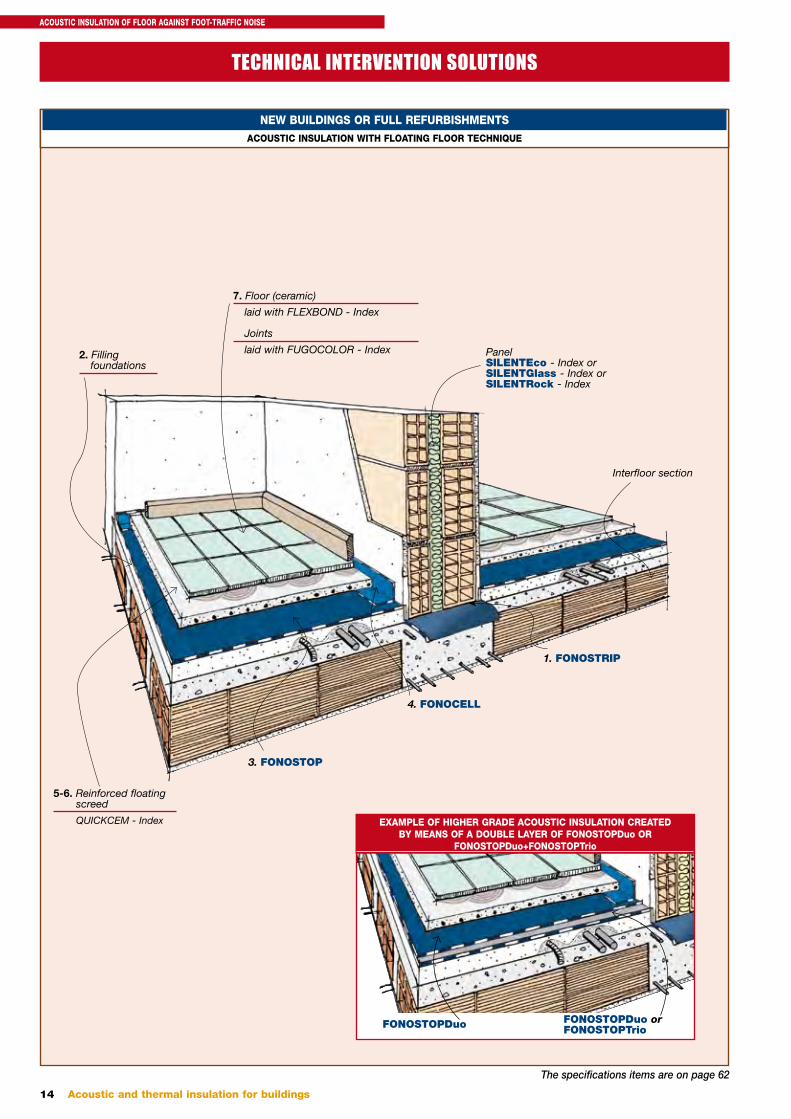
Laying FONOSTRIP. The load-bearing floor slab is generally made of cement and brick. The insulating strips on which the dividing walls will be built are laid on this floor slab. FONOSTRIP is an elastomeric insulation product supplied in strips of different heights. It dampens vibrations on the walls. A wall that is not insulated increases lateral noise transmissions.
SUBSTRATE PREPARATION
Acoustic insulation of piping. Wrap any pipes that cross the floor slab with adhesive elastic strips. A pipe that is not insulated transmits noise.
Avoid to!
Lateral separation. Insulate the foundations from the walls with adhesive extruded polyethylene strips measuring 2÷3 mm in thickness and 1÷2 cm higher than the foundations. Lateral noise transmissions will increase if the strip is not used.
Avoid to!
Avoid to!
NOISE
without FONOSTRIP
FONOSTRIP
Expanded polyethylene foam
Expanded polyethylene foam
NOISE
without expanded polyethylene foam
NOISE
without expanded polyethylene foam
Filling substrate. The piping laid previously on the floor slab are embedded in the filling foundations and joined with cement mortar. Filling can be done using lightened concrete or sand stabilised with lime or cement (ratio 50÷100 kg/m3). The foundations shall be smooth and flat, free from bumps and dips. Irregular foundations will cause the insulation to be squashed excessively, consequently noise will be transmitted.
Avoid to!
Substrate
NOISEUneven substrate
ACOUSTIC INSULATION OF FLOOR AGAINST FOOT-TRAFFIC NOISE
16 Acoustic and thermal insulation for buildings
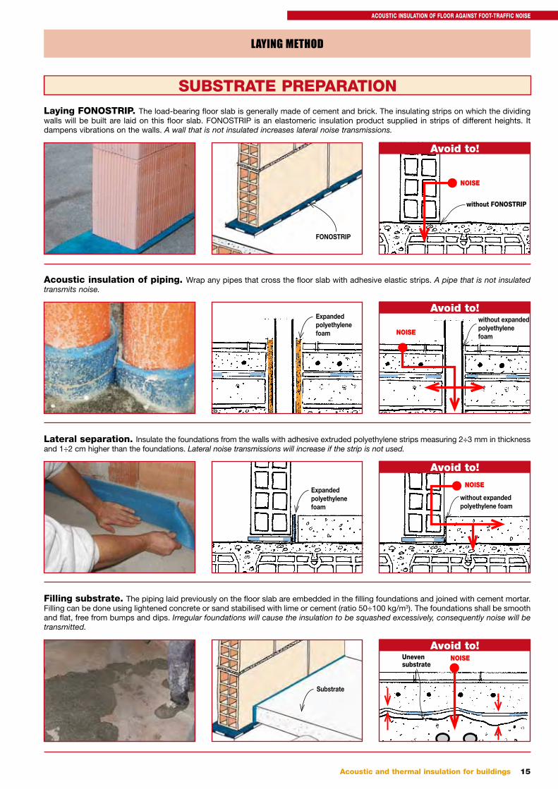
Clean the support. Make sure no dirt, lumps of mortar and plaster are left on the laying surface. Dirt and irregularities could perforate the insulation material and reduce its acoustic insulation performance.
Avoid to!
Once the foundations have been laid, pla-ster the walls before laying FONOSTOP.
LAYING THE FONOSTOP
PLASTERING THE WALLS
Clean substrate
Foreign bodies
Laying FONOSTOPDuo in single layers. The insulation layer must withstand site traffic and must be made of durable and non-rotting materials.FONOSTOPDuo is an acoustic insulation product against foot traffic noise that meets the afore-mentioned requirements. It offers very high per-formance even if rather thin. Lay the rolls out in their natural unrolling direction, making sure to arrange the bottom face (downwards) and the top face (upwards) as indicated for each type of FONOSTOP product. If FONOSTOP is laid upside down, it would be soaked with mortar and consequently lose its insulating power.
Avoid to! Upperface
Underface
Underface
Upperface
Side overlaps. FONOSTOPDuo has a built-in overlap wing of 5 cm. Overlap the sheets in the longitudinal direction along the special overlap strip, matching them up with care (except for FONOSTOPBar and FONOSTOPCell which are just set next to each other). Incorrect overlapping could cause an acoustic bridge and reduce the insulating performance.
Overlap Avoid to!NOISEAcoustic bridge
ACOUSTIC INSULATION OF FLOOR AGAINST FOOT-TRAFFIC NOISE
17Acoustic and thermal insulation for buildings
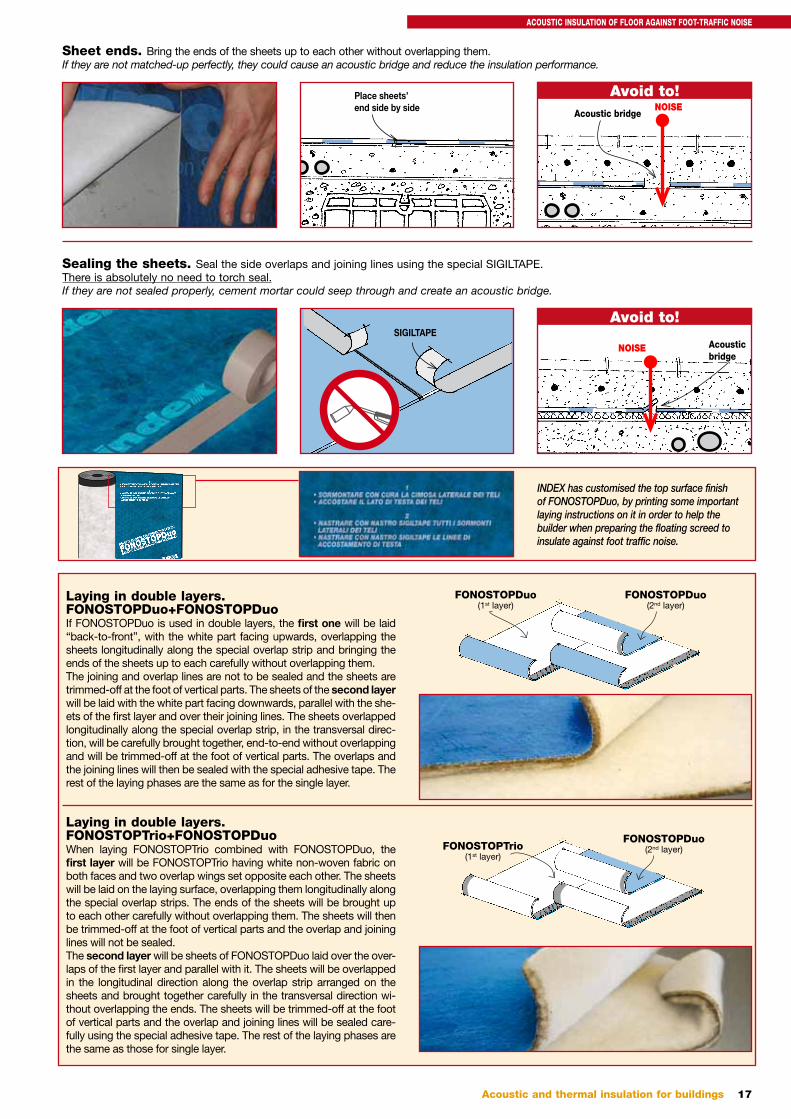
Sheet ends. Bring the ends of the sheets up to each other without overlapping them.If they are not matched-up perfectly, they could cause an acoustic bridge and reduce the insulation performance.
Sealing the sheets. Seal the side overlaps and joining lines using the special SIGILTAPE. There is absolutely no need to torch seal. If they are not sealed properly, cement mortar could seep through and create an acoustic bridge.
Place sheets’end side by side
SIGILTAPE
Avoid to!NOISE
Acoustic bridge
Avoid to!
NOISE Acoustic bridge
FONOSTOPDuo(1st layer)
FONOSTOPDuo(2nd layer)
Laying in double layers.FONOSTOPDuo+FONOSTOPDuoIf FONOSTOPDuo is used in double layers, the first one will be laid “back-to-front”, with the white part facing upwards, overlapping the sheets longitudinally along the special overlap strip and bringing the ends of the sheets up to each carefully without overlapping them.The joining and overlap lines are not to be sealed and the sheets are trimmed-off at the foot of vertical parts. The sheets of the second layer will be laid with the white part facing downwards, parallel with the she-ets of the first layer and over their joining lines. The sheets overlapped longitudinally along the special overlap strip, in the transversal direc-tion, will be carefully brought together, end-to-end without overlapping and will be trimmed-off at the foot of vertical parts. The overlaps and the joining lines will then be sealed with the special adhesive tape. The rest of the laying phases are the same as for the single layer.
Laying in double layers.FONOSTOPTrio+FONOSTOPDuoWhen laying FONOSTOPTrio combined with FONOSTOPDuo, the first layer will be FONOSTOPTrio having white non-woven fabric on both faces and two overlap wings set opposite each other. The sheets will be laid on the laying surface, overlapping them longitudinally along the special overlap strips. The ends of the sheets will be brought up to each other carefully without overlapping them. The sheets will then be trimmed-off at the foot of vertical parts and the overlap and joining lines will not be sealed.The second layer will be sheets of FONOSTOPDuo laid over the over-laps of the first layer and parallel with it. The sheets will be overlapped in the longitudinal direction along the overlap strip arranged on the sheets and brought together carefully in the transversal direction wi-thout overlapping the ends. The sheets will be trimmed-off at the foot of vertical parts and the overlap and joining lines will be sealed care-fully using the special adhesive tape. The rest of the laying phases are the same as those for single layer.
FONOSTOPTrio(1st layer)
FONOSTOPDuo(2nd layer)
INDEX has customised the top surface finish of FONOSTOPDuo, by printing some important laying instructions on it in order to help the builder when preparing the floating screed to insulate against foot traffic noise.
ACOUSTIC INSULATION OF FLOOR AGAINST FOOT-TRAFFIC NOISE
18 Acoustic and thermal insulation for buildings
CREATING THE SCREED
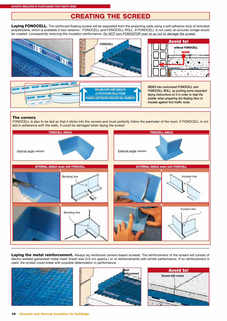
Laying the metal reinforcement. Always lay reinforced cement-based screeds. The reinforcement of the screed will consist of electro-welded galvanised metal mesh (mesh size 5×5 cm approx.) or of reinforcements with similar performance. If no reinforcement is used, the screed could break with possible deterioration in performance.
Avoid to!
The cornersFONOCELL is also to be laid so that it sticks into the corners and must perfectly follow the perimeter of the room. If FONOCELL is not laid in adherence with the walls, it could be damaged when laying the screed.
FONOCELL ANGLE
Internal angle version
EXTERNAL ANGLE made with FONOCELL
Incision line
1
Incision line
2
INTERNAL ANGLE made with FONOCELL
Bonding line
1
Bonding line
2
FONOCELL ANGLE
External angle version
Metal reinforcement
Laying FONOCELL. The reinforced floating screed will be separated from the projecting walls using a self-adhesive strip of extruded polyethylene, which is available in two versions - FONOCELL and FONOCELL ROLL. If FONOCELL is not used, an acoustic bridge would be created, consequently reducing the insulation performance. Do NOT turn FONOSTOP over so as not to damage the screed.
Avoid to!FONOCELL
NOISE
without FONOCELL
Screed with cracks
RIFILARE DOPO AVER ESEGUITO
LA STUCCATURA DELLE FUGHE
POSARE IL BATTISCOPA STACCATO DAL PAVIMENTO
TRIM AFTER GROUTING THE JOINTS
LAY THE SKIRTING BOARD
DETACHED FROM THE FLOOR
RIFILARE DOPO AVER ESEGUITO
LA STUCCATURA DELLE FUGHE
POSARE IL BATTISCOPA STACCATO DAL PAVIMENTO
TRIM AFTER GROUTING THE JOINTS
LAY THE SKIRTING BOARD
DETACHED FROM THE FLOOR
RIFILARE DOPO AVER ESEGUITO
LA STUCCATURA DELLE FUGHE
POSARE IL BATTISCOPA STACCATO DAL PAVIMENTO
TRIM AFTER GROUTING THE JOINTS
LAY THE SKIRTING BOARD
DETACHED FROM THE FLOOR
RIFILARE DOPO AVER ESEGUITO
LA STUCCATURA DELLE FUGHE
POSARE IL BATTISCOPA STACCATO DAL PAV
INDEX has customised FONOCELL and FONOCELL ROLL, by printing some important laying instructions on it in order to help the builder when preparing the floating floor to insulate against foot traffic noise.
RIFILARE DOPO AVER ESEGUITO
LA STUCCATURA DELLE FUGHE
POSARE IL BATTISCOPA STACCATO DAL PAVIMENTO
TRIM AFTER GROUTING THE JOINTS
LAY THE SKIRTING BOARD
DETACHED FROM THE FLOOR
RIFILARE DOPO AVER ESEGUITO
LA STUCCATURA DELLE FUGHE
POSARE IL BATTISCOPA STACCATO DAL PAVIMENTO
TRIM AFTER GROUTING THE JOINTS
LAY THE SKIRTING BOARD
DETACHED FROM THE FLOOR
RIFILARE DOPO AVER ESEGUITOLA STUCCATURA DELLE FUGHE
POSARE IL BATTISCOPA STACCATO DAL PAVIMENTO
TRIM AFTER GROUTING THE JOINTSLAY THE SKIRTING BOARD
DETACHED FROM THE FLOOR
ACOUSTIC INSULATION OF FLOOR AGAINST FOOT-TRAFFIC NOISE
19Acoustic and thermal insulation for buildings
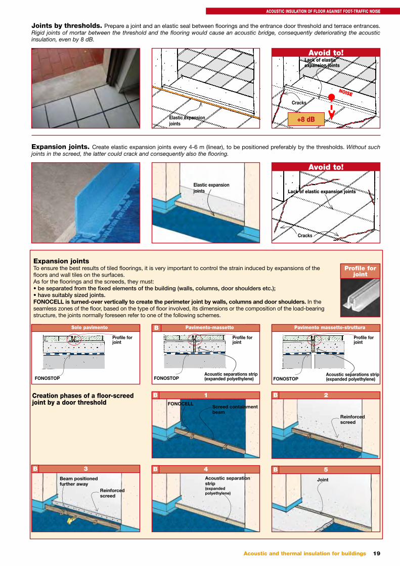
Expansion jointsTo ensure the best results of tiled floorings, it is very important to control the strain induced by expansions of the floors and wall tiles on the surfaces.As for the floorings and the screeds, they must:• be separated from the fixed elements of the building (walls, columns, door shoulders etc.);• have suitably sized joints.FONOCELL is turned-over vertically to create the perimeter joint by walls, columns and door shoulders. In the seamless zones of the floor, based on the type of floor involved, its dimensions or the composition of the load-bearing structure, the joints normally foreseen refer to one of the following schemes.
Expansion joints. Create elastic expansion joints every 4-6 m (linear), to be positioned preferably by the thresholds. Without such joints in the screed, the latter could crack and consequently also the flooring.
Avoid to!
Joints by thresholds. Prepare a joint and an elastic seal between floorings and the entrance door threshold and terrace entrances. Rigid joints of mortar between the threshold and the flooring would cause an acoustic bridge, consequently deteriorating the acoustic insulation, even by 8 dB.
Avoid to!
Profile for joint
A Solo pavimento
FONOSTOP
Profile forjoint
CPavimento-massettoB
FONOSTOPAcoustic separations strip(expanded polyethylene)
Profile forjoint
Pavimento massetto-struttura
FONOSTOPAcoustic separations strip(expanded polyethylene)
Profile forjoint
Creation phases of a floor-screed joint by a door threshold
4Acoustic separation strip(expanded polyethylene)
B 5
Joint
B
2
Reinforcedscreed
B
3
Beam positioned further away
Reinforcedscreed
B
1FONOCELL
Screed containment beam
B
Elastic expansion joints
NOISE
Lack of elastic expansion joints
Cracks
+8 dB
Elastic expansion joints Lack of elastic expansion joints
Cracks
ACOUSTIC INSULATION OF FLOOR AGAINST FOOT-TRAFFIC NOISE
20 Acoustic and thermal insulation for buildings
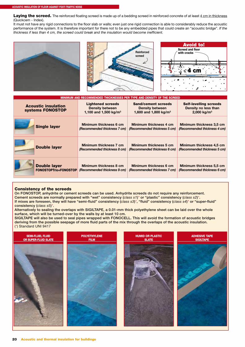
Laying the screed. The reinforced floating screed is made up of a bedding screed in reinforced concrete of at least 4 cm in thickness (Quickcem - Index). It must not have any rigid connections to the floor slab or walls; even just one rigid connection is able to considerably reduce the acoustic performance of the system. It is therefore important for there not to be any embedded pipes that could create an “acoustic bridge”. If the thickness if less than 4 cm, the screed could break and the insulation would become inefficient.
Avoid to!
Consistency of the screedsOn FONOSTOP, anhydrite or cement screeds can be used. Anhydrite screeds do not require any reinforcement. Cement screeds are normally prepared with “wet” consistency (class s1)* or “plastic” consistency (class s2)*. If mixes are foreseen, they will have “semi-fluid” consistency (class s3)*, “fluid” consistency (class s4)* or “super-fluid” consistency (class s5)*. Alternatively to sealing the overlaps with SIGILTAPE, a 0.01-mm thick polyethylene sheet can be laid over the whole surface, which will be turned-over by the walls by at least 10 cm.SIGILTAPE will also be used to seal pipes wrapped with FONOCELL. This will avoid the formation of acoustic bridges deriving from the possible seepage of more fluid parts of the mix through the overlaps of the acoustic insulation.(*) Standard UNI 9417
SEMI-FLUID, FLUID OR SUPER-FLUID SLATE
HUMID OR PLASTIC SLATE
POLYETHYLENE FILM
ADHESIVE TAPE SIGILTAPE
Acoustic insulation systems FONOSTOP
Single layer
Double layer
Double layerFONOSTOPTrio+FONOSTOP
Minimum thickness 6 cm(Recommended thickness 7 cm)
Minimum thickness 7 cm(Recommended thickness 8 cm)
Minimum thickness 8 cm(Recommended thickness 9 cm)
Minimum thickness 4 cm(Recommended thickness 5 cm)
Minimum thickness 5 cm(Recommended thickness 6 cm)
Minimum thickness 6 cm(Recommended thickness 7 cm)
Minimum thickness 3,5 cm(Recommended thickness 4 cm)
Minimum thickness 4,5 cm(Recommended thickness 5 cm)
Minimum thickness 5,5 cm(Recommended thickness 6 cm)
MINIMUM AND RECOMMENDED THICKNESSES PER TYPE AND DENSITY OF THE SCREED
Lightened screeds Density between
1,100 and 1,500 kg/m3
Sand/cement screeds Density between
1,600 and 1,800 kg/m3
Self-levelling screeds Density no less than
2,000 kg/m3
< 4 cm
Screed and floor with cracksReinforced
screed
ACOUSTIC INSULATION OF FLOOR AGAINST FOOT-TRAFFIC NOISE
21Acoustic and thermal insulation for buildings
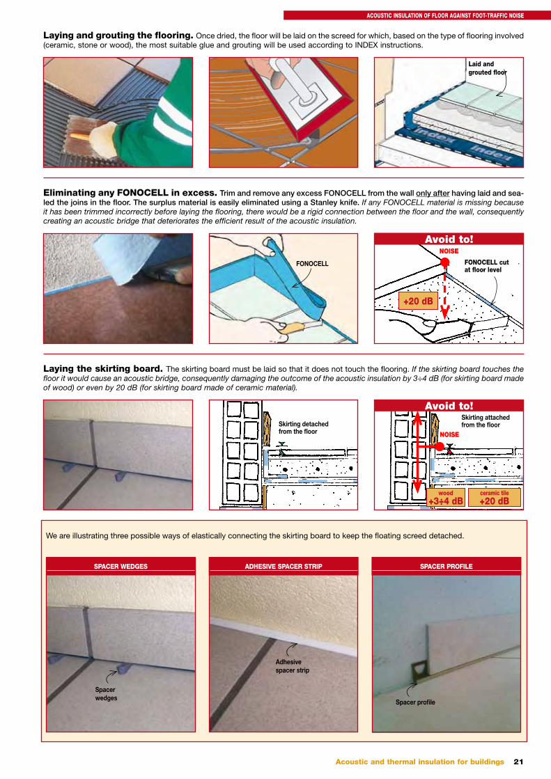
Laying and grouting the flooring. Once dried, the floor will be laid on the screed for which, based on the type of flooring involved (ceramic, stone or wood), the most suitable glue and grouting will be used according to INDEX instructions.
Eliminating any FONOCELL in excess. Trim and remove any excess FONOCELL from the wall only after having laid and sea-led the joins in the floor. The surplus material is easily eliminated using a Stanley knife. If any FONOCELL material is missing because it has been trimmed incorrectly before laying the flooring, there would be a rigid connection between the floor and the wall, consequently creating an acoustic bridge that deteriorates the efficient result of the acoustic insulation.
Laying the skirting board. The skirting board must be laid so that it does not touch the flooring. If the skirting board touches the floor it would cause an acoustic bridge, consequently damaging the outcome of the acoustic insulation by 3÷4 dB (for skirting board made of wood) or even by 20 dB (for skirting board made of ceramic material).
Avoid to!
Avoid to!
We are illustrating three possible ways of elastically connecting the skirting board to keep the floating screed detached.
Laid and grouted floor
FONOCELL
NOISE
FONOCELL cut at floor level
+20 dB
Skirting detached from the floor NOISE
Skirting attached from the floor
wood+3÷4 dB
ceramic tile+20 dB
SPACER WEDGES
Spacer wedges
ADHESIVE SPACER STRIP
Adhesive spacer strip
SPACER PROFILE
Spacer profile
ACOUSTIC INSULATION OF FLOOR AGAINST FOOT-TRAFFIC NOISE
22 Acoustic and thermal insulation for buildings
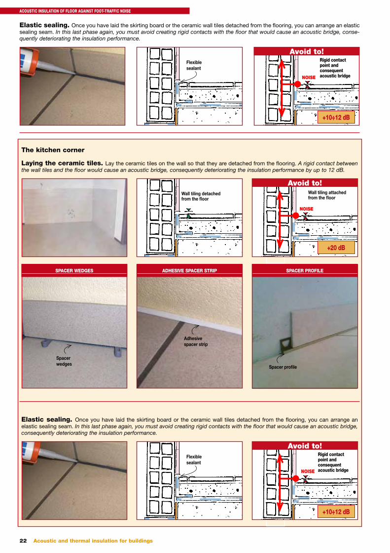
The kitchen corner
Laying the ceramic tiles. Lay the ceramic tiles on the wall so that they are detached from the flooring. A rigid contact between the wall tiles and the floor would cause an acoustic bridge, consequently deteriorating the insulation performance by up to 12 dB.
Wall tiling detached from the floor
Avoid to!
NOISE
Wall tiling attached from the floor
+20 dB
SPACER WEDGES
Spacer wedges
ADHESIVE SPACER STRIP
Adhesive spacer strip
SPACER PROFILE
Spacer profile
Elastic sealing. Once you have laid the skirting board or the ceramic wall tiles detached from the flooring, you can arrange an elastic sealing seam. In this last phase again, you must avoid creating rigid contacts with the floor that would cause an acoustic bridge, consequently deteriorating the insulation performance.
Avoid to!
NOISE
Rigid contact point and consequent acoustic bridge
Flexible sealant
+10÷12 dB
Elastic sealing. Once you have laid the skirting board or the ceramic wall tiles detached from the flooring, you can arrange an elastic sealing seam. In this last phase again, you must avoid creating rigid contacts with the floor that would cause an acoustic bridge, conse-quently deteriorating the insulation performance.
Avoid to!
NOISE
Rigid contact point and consequent acoustic bridge
Flexible sealant
+10÷12 dB
ACOUSTIC INSULATION OF FLOOR AGAINST FOOT-TRAFFIC NOISE
23Acoustic and thermal insulation for buildings
DETAILS
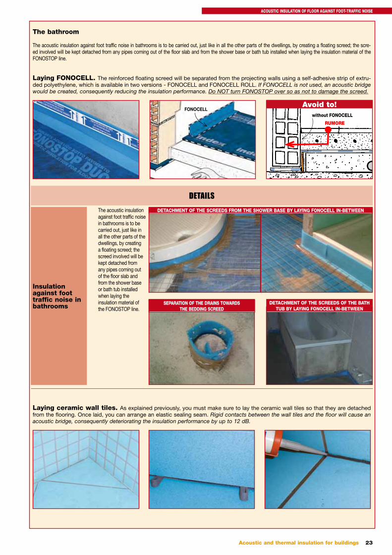
Insulation against foot traffic noise in bathrooms
The acoustic insulation against foot traffic noise in bathrooms is to be carried out, just like in all the other parts of the dwellings, by creating a floating screed; the screed involved will be kept detached from any pipes coming out of the floor slab and from the shower base or bath tub installed when laying the insulation material of the FONOSTOP line.
DETACHMENT OF THE SCREEDS FROM THE SHOWER BASE BY LAYING FONOCELL IN-BETWEEN
SEPARATION OF THE DRAINS TOWARDS THE BEDDING SCREED
DETACHMENT OF THE SCREEDS OF THE BATH TUB BY LAYING FONOCELL IN-BETWEEN
The bathroom
The acoustic insulation against foot traffic noise in bathrooms is to be carried out, just like in all the other parts of the dwellings, by creating a floating screed; the scre-ed involved will be kept detached from any pipes coming out of the floor slab and from the shower base or bath tub installed when laying the insulation material of the FONOSTOP line.
Laying ceramic wall tiles. As explained previously, you must make sure to lay the ceramic wall tiles so that they are detached from the flooring. Once laid, you can arrange an elastic sealing seam. Rigid contacts between the wall tiles and the floor will cause an acoustic bridge, consequently deteriorating the insulation performance by up to 12 dB.
Laying FONOCELL. The reinforced floating screed will be separated from the projecting walls using a self-adhesive strip of extru-ded polyethylene, which is available in two versions - FONOCELL and FONOCELL ROLL. If FONOCELL is not used, an acoustic bridge would be created, consequently reducing the insulation performance. Do NOT turn FONOSTOP over so as not to damage the screed.
FONOCELLAvoid to!
RUMORE
without FONOCELL
ACOUSTIC INSULATION OF FLOOR AGAINST FOOT-TRAFFIC NOISE
24 Acoustic and thermal insulation for buildings
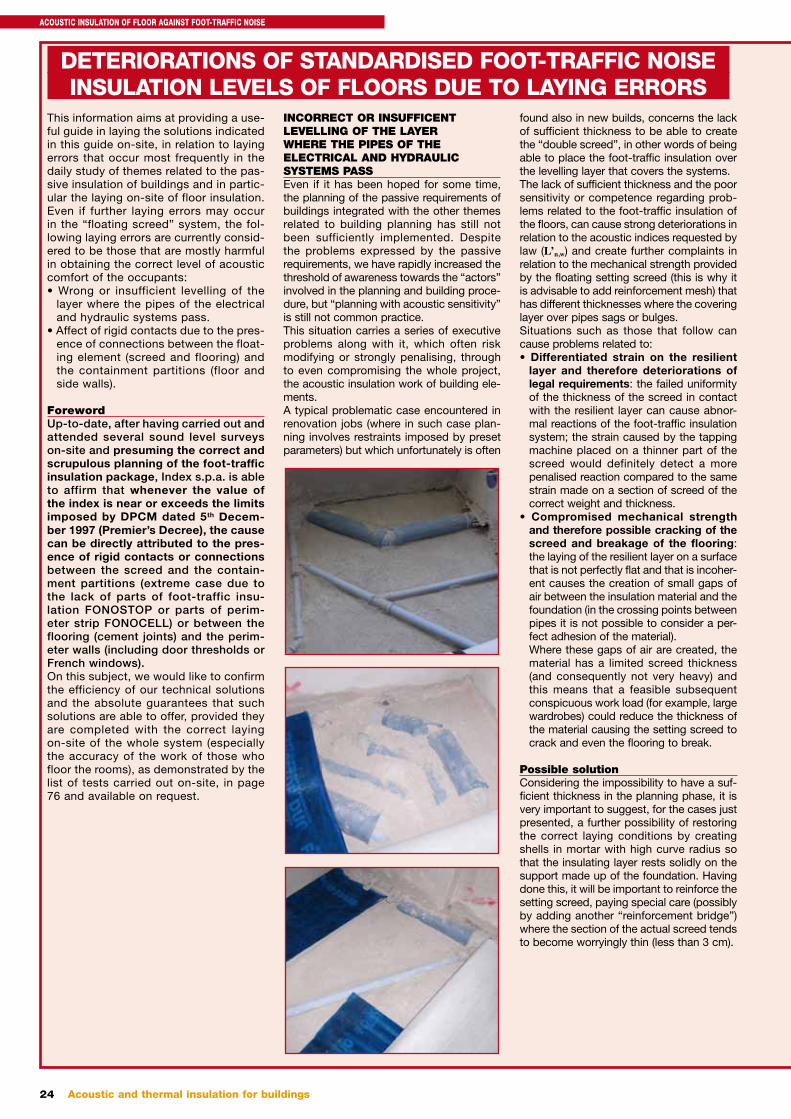
This information aims at providing a use-ful guide in laying the solutions indicated in this guide on-site, in relation to laying errors that occur most frequently in the daily study of themes related to the pas-sive insulation of buildings and in partic-ular the laying on-site of floor insulation.Even if further laying errors may occur in the “floating screed” system, the fol-lowing laying errors are currently consid-ered to be those that are mostly harmful in obtaining the correct level of acoustic comfort of the occupants:• Wrong or insufficient levelling of the
layer where the pipes of the electrical and hydraulic systems pass.
• Affect of rigid contacts due to the pres-ence of connections between the float-ing element (screed and flooring) and the containment partitions (floor and side walls).
ForewordUp-to-date, after having carried out and attended several sound level surveys on-site and presuming the correct and scrupulous planning of the foot-traffic insulation package, Index s.p.a. is able to affirm that whenever the value of the index is near or exceeds the limits imposed by DPCM dated 5th Decem-ber 1997 (Premier’s Decree), the cause can be directly attributed to the pres-ence of rigid contacts or connections between the screed and the contain-ment partitions (extreme case due to the lack of parts of foot-traffic insu-lation FONOSTOP or parts of perim-eter strip FONOCELL) or between the flooring (cement joints) and the perim-eter walls (including door thresholds or French windows).On this subject, we would like to confirm the efficiency of our technical solutions and the absolute guarantees that such solutions are able to offer, provided they are completed with the correct laying on-site of the whole system (especially the accuracy of the work of those who floor the rooms), as demonstrated by the list of tests carried out on-site, in page 76 and available on request.
INCORRECT OR INSUFFICENT LEVELLING OF THE LAYER WHERE THE PIPES OF THE ELECTRICAL AND HYDRAULIC SYSTEMS PASSEven if it has been hoped for some time, the planning of the passive requirements of buildings integrated with the other themes related to building planning has still not been sufficiently implemented. Despite the problems expressed by the passive requirements, we have rapidly increased the threshold of awareness towards the “actors” involved in the planning and building proce-dure, but “planning with acoustic sensitivity” is still not common practice.This situation carries a series of executive problems along with it, which often risk modifying or strongly penalising, through to even compromising the whole project, the acoustic insulation work of building ele-ments.A typical problematic case encountered in renovation jobs (where in such case plan-ning involves restraints imposed by preset parameters) but which unfortunately is often
found also in new builds, concerns the lack of sufficient thickness to be able to create the “double screed”, in other words of being able to place the foot-traffic insulation over the levelling layer that covers the systems.The lack of sufficient thickness and the poor sensitivity or competence regarding prob-lems related to the foot-traffic insulation of the floors, can cause strong deteriorations in relation to the acoustic indices requested by law (L’n,w) and create further complaints in relation to the mechanical strength provided by the floating setting screed (this is why it is advisable to add reinforcement mesh) that has different thicknesses where the covering layer over pipes sags or bulges. Situations such as those that follow can cause problems related to:• Differentiated strain on the resilient
layer and therefore deteriorations of legal requirements: the failed uniformity of the thickness of the screed in contact with the resilient layer can cause abnor-mal reactions of the foot-traffic insulation system; the strain caused by the tapping machine placed on a thinner part of the screed would definitely detect a more penalised reaction compared to the same strain made on a section of screed of the correct weight and thickness.
• Compromised mechanical strength and therefore possible cracking of the screed and breakage of the flooring: the laying of the resilient layer on a surface that is not perfectly flat and that is incoher-ent causes the creation of small gaps of air between the insulation material and the foundation (in the crossing points between pipes it is not possible to consider a per-fect adhesion of the material).Where these gaps of air are created, the material has a limited screed thickness (and consequently not very heavy) and this means that a feasible subsequent conspicuous work load (for example, large wardrobes) could reduce the thickness of the material causing the setting screed to crack and even the flooring to break.
Possible solutionConsidering the impossibility to have a suf-ficient thickness in the planning phase, it is very important to suggest, for the cases just presented, a further possibility of restoring the correct laying conditions by creating shells in mortar with high curve radius so that the insulating layer rests solidly on the support made up of the foundation. Having done this, it will be important to reinforce the setting screed, paying special care (possibly by adding another “reinforcement bridge”) where the section of the actual screed tends to become worryingly thin (less than 3 cm).
DETERIORATIONS OF STANDARDISED FOOT-TRAFFIC NOISEINSULATION LEVELS OF FLOORS DUE TO LAYING ERRORS
ACOUSTIC INSULATION OF FLOOR AGAINST FOOT-TRAFFIC NOISE
25Acoustic and thermal insulation for buildings
AFFECT OF RIGID CONTACTS ATTRIBUTABLE TO THE PRESENCE OF CONNECTIONS BETWEEN THE FLOATING ELEMENT AND THE CONTAINMENT PARTITIONSThe information that follows is the summa-ry of the site experiment campaign carried out in depth by Index s.p.a. with the aim to characterise the performance of the float-ing screeds insulated with our systems and to identify, and possibly quantify, the risks related to the incorrect laying on-site of the foot-traffic insulation system, also evaluat-ing and measuring consequent deteriora-tions. Before we enter into the details of the site experiments, we should discuss the experiment parameters, not merely to boast our skills, but more so to provide a valid support in interpreting the meaning of the test reports following the experimental site tests.
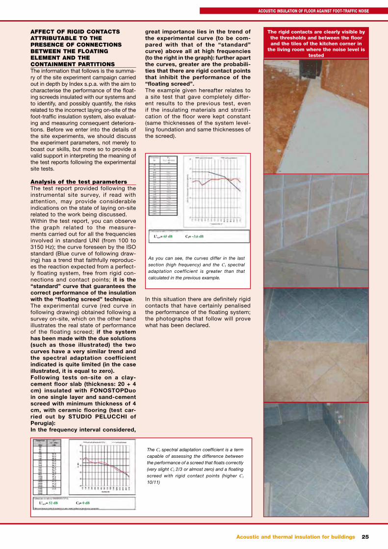
Analysis of the test parametersThe test report provided following the instrumental site survey, if read with attention, may provide considerable indications on the state of laying on-site related to the work being discussed.Within the test report, you can observe the graph related to the measure-ments carried out for all the frequencies involved in standard UNI (from 100 to 3150 Hz); the curve foreseen by the ISO standard (Blue curve of following draw-ing) has a trend that faithfully reproduc-es the reaction expected from a perfect-ly floating system, free from rigid con-nections and contact points; it is the “standard” curve that guarantees the correct performance of the insulation with the “floating screed” technique.The experimental curve (red curve in following drawing) obtained following a survey on-site, which on the other hand illustrates the real state of performance of the floating screed; if the system has been made with the due solutions (such as those illustrated) the two curves have a very similar trend and the spectral adaptation coefficient indicated is quite limited (in the case illustrated, it is equal to zero).Following tests on-site on a clay-cement floor slab (thickness: 20 + 4 cm) insulated with FONOSTOPDuo in one single layer and sand-cement screed with minimum thickness of 4 cm, with ceramic flooring (test car-ried out by STUDIO PELUCCHI of Perugia):In the frequency interval considered,
great importance lies in the trend of the experimental curve (to be com-pared with that of the “standard” curve) above all at high frequencies (to the right in the graph): further apart the curves, greater are the probabili-ties that there are rigid contact points that inhibit the performance of the “floating screed”.The example given hereafter relates to a site test that gave completely differ-ent results to the previous test, even if the insulating materials and stratifi-cation of the floor were kept constant (same thicknesses of the system level-ling foundation and same thicknesses of the screed).
In this situation there are definitely rigid contacts that have certainly penalised the performance of the floating system; the photographs that follow will prove what has been declared.
The rigid contacts are clearly visible by the thresholds and between the floor and the tiles of the kitchen corner in
the living room where the noise level is tested
The CI spectral adaptation coefficient is a term capable of assessing the difference between the performance of a screed that floats correctly (very slight CI 2/3 or almost zero) and a floating screed with rigid contact points (higher CI 10/11)
L’n,w= 52 dB CI= 0 dB
As you can see, the curves differ in the last section (high frequency) and the CI spectral adaptation coefficient is greater than that calculated in the previous example.
L’n,w= 65 dB CI= –3,6 dB
ACOUSTIC INSULATION OF FLOOR AGAINST FOOT-TRAFFIC NOISE
26 Acoustic and thermal insulation for buildings
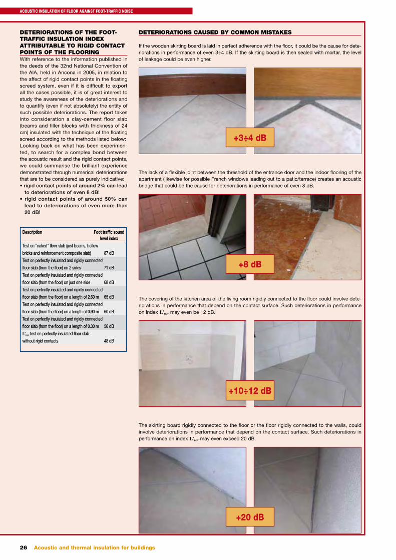
DETERIORATIONS OF THE FOOT-TRAFFIC INSULATION INDEX ATTRIBUTABLE TO RIGID CONTACT POINTS OF THE FLOORINGWith reference to the information published in the deeds of the 32nd National Convention of the AIA, held in Ancona in 2005, in relation to the affect of rigid contact points in the floating screed system, even if it is difficult to export all the cases possible, it is of great interest to study the awareness of the deteriorations and to quantify (even if not absolutely) the entity of such possible deteriorations. The report takes into consideration a clay-cement floor slab (beams and filler blocks with thickness of 24 cm) insulated with the technique of the floating screed according to the methods listed below:Looking back on what has been experimen-ted, to search for a complex bond between the acoustic result and the rigid contact points, we could summarise the brilliant experience demonstrated through numerical deteriorations that are to be considered as purely indicative:• rigid contact points of around 2% can lead
to deteriorations of even 8 dB!• rigid contact points of around 50% can
lead to deteriorations of even more than 20 dB!
Description Foot traffic sound level indexTest on “naked” floor slab (just beams, hollow
bricks and reinforcement composite slab) 87 dB
Test on perfectly insulated and rigidly connected
floor slab (from the floor) on 2 sides 71 dB
Test on perfectly insulated and rigidly connected
floor slab (from the floor) on just one side 68 dB
Test on perfectly insulated and rigidly connected
floor slab (from the floor) on a length of 2.60 m 65 dB
Test on perfectly insulated and rigidly connected
floor slab (from the floor) on a length of 0.90 m 60 dB
Test on perfectly insulated and rigidly connected
floor slab (from the floor) on a length of 0.30 m 56 dB
L’n,w test on perfectly insulated floor slab
without rigid contacts 48 dB
DETERIORATIONS CAUSED BY COMMON MISTAKES
If the wooden skirting board is laid in perfect adherence with the floor, it could be the cause for dete-riorations in performance of even 3÷4 dB. If the skirting board is then sealed with mortar, the level of leakage could be even higher.
The lack of a flexible joint between the threshold of the entrance door and the indoor flooring of the apartment (likewise for possible French windows leading out to a patio/terrace) creates an acoustic bridge that could be the cause for deteriorations in performance of even 8 dB.
The covering of the kitchen area of the living room rigidly connected to the floor could involve dete-riorations in performance that depend on the contact surface. Such deteriorations in performance on index L’n,w may even be 12 dB.
The skirting board rigidly connected to the floor or the floor rigidly connected to the walls, could involve deteriorations in performance that depend on the contact surface. Such deteriorations in performance on index L’n,w may even exceed 20 dB.
+3÷4 dB
+8 dB
+10÷12 dB
+20 dB
ACOUSTIC INSULATION OF FLOOR AGAINST FOOT-TRAFFIC NOISE


![Pageflex Server [document: D-2B93D969 00001] · TOPFLOW SCREED A SKY, THE SHARD, LONDON FLOW SCREED A SKY . 0000/0015 Tarmac's Topflow Screed A Sky is a blend of synthetic calcium](https://img.pdfslide.us/doc/110x75/5f697cdb45b2c12b5f31c2cc/pageflex-server-document-d-2b93d969-00001-topflow-screed-a-sky-the-shard-london.jpg)