Embed Size (px)
Citation preview
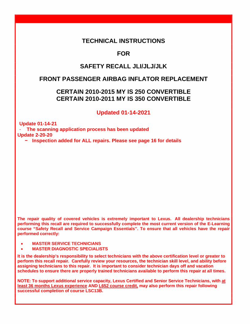
TECHNICAL INSTRUCTIONS
FOR
SAFETY RECALL JLI/JLJ/JLK
FRONT PASSENGER AIRBAG INFLATOR REPLACEMENT
CERTAIN 2010-2015 MY IS 250 CONVERTIBLE CERTAIN 2010-2011 MY IS 350 CONVERTIBLE
Updated 01-14-2021
Update 01-14-21 - The scanning application process has been updated
Update 2-20-20 − Inspection added for ALL repairs. Please see page 16 for details
The repair quality of covered vehicles is extremely important to Lexus. All dealership technicians performing this recall are required to successfully complete the most current version of the E-Learning course “Safety Recall and Service Campaign Essentials”. To ensure that all vehicles have the repair performed correctly: • MASTER SERVICE TECHNICIANS • MASTER DIAGNOSTIC SPECIALISTS
It is the dealership’s responsibility to select technicians with the above certification level or greater to perform this recall repair. Carefully review your resources, the technician skill level, and ability before assigning technicians to this repair. It is important to consider technician days off and vacation schedules to ensure there are properly trained technicians available to perform this repair at all times. NOTE: To support additional service capacity, Lexus Certified and Senior Service Technicians, with at least 36 months Lexus experience AND L652 course credit, may also perform this repair following successful completion of course LSC13B.
2
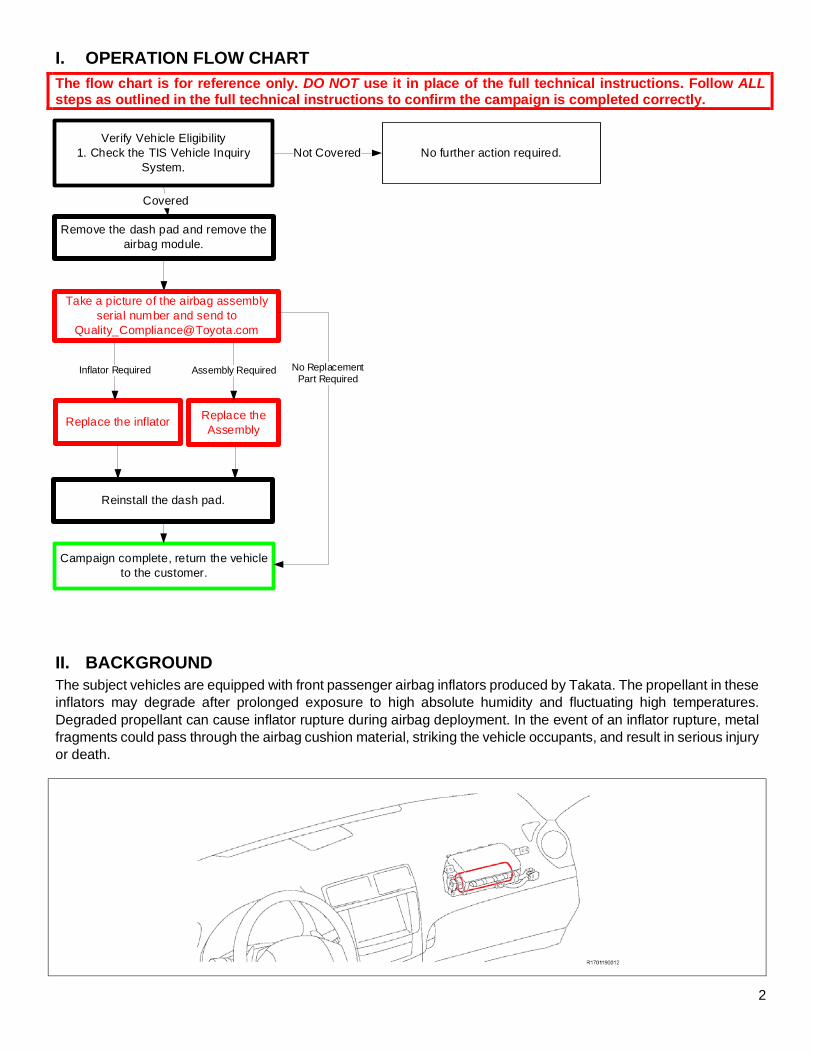
I. OPERATION FLOW CHART
The flow chart is for reference only. DO NOT use it in place of the full technical instructions. Follow ALL steps as outlined in the full technical instructions to confirm the campaign is completed correctly.
Verify Vehicle Eligibility1. Check the TIS Vehicle Inquiry
System.No further action required.Not Covered
Campaign complete, return the vehicle to the customer.
Covered
Replace the inflator
Reinstall the dash pad.
Replace the Assembly
Remove the dash pad and remove the airbag module.
Inflator Required
Take a picture of the airbag assembly serial number and send to
Assembly Required No ReplacementPart Required
II. BACKGROUND
The subject vehicles are equipped with front passenger airbag inflators produced by Takata. The propellant in these inflators may degrade after prolonged exposure to high absolute humidity and fluctuating high temperatures. Degraded propellant can cause inflator rupture during airbag deployment. In the event of an inflator rupture, metal fragments could pass through the airbag cushion material, striking the vehicle occupants, and result in serious injury or death.
3
III. IDENTIFICATION OF AFFECTED VEHICLES
A. COVERED VIN RANGE
• Check the TIS Vehicle Inquiry System to confirm the VIN is involved in this Safety Recall, and that the campaign has not already been completed prior to dealer shipment or by another dealer.
• TMS warranty will not reimburse dealers for repairs conducted on vehicles that are not affected or were completed by another dealer.
IV. PREPARATION
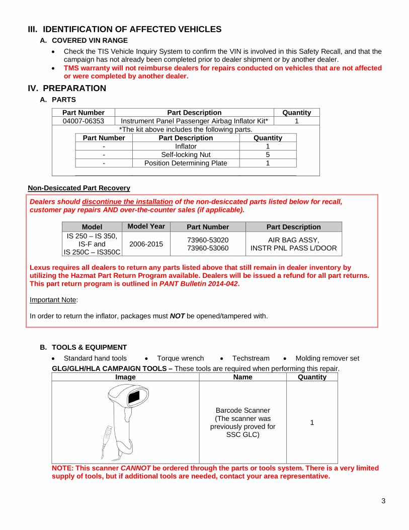
A. PARTS
Part Number Part Description Quantity 04007-06353 Instrument Panel Passenger Airbag Inflator Kit* 1
*The kit above includes the following parts. Part Number Part Description Quantity
- Inflator 1 - Self-locking Nut 5 - Position Determining Plate 1
Non-Desiccated Part Recovery
B. TOOLS & EQUIPMENT
• Standard hand tools • Torque wrench • Techstream • Molding remover set
GLG/GLH/HLA CAMPAIGN TOOLS – These tools are required when performing this repair. Image Name Quantity
Barcode Scanner (The scanner was
previously proved for SSC GLC)
1
NOTE: This scanner CANNOT be ordered through the parts or tools system. There is a very limited supply of tools, but if additional tools are needed, contact your area representative.
Dealers should discontinue the installation of the non-desiccated parts listed below for recall, customer pay repairs AND over-the-counter sales (if applicable).
Model Model Year Part Number Part Description IS 250 – IS 350,
IS-F and IS 250C – IS350C
2006-2015 73960-53020 73960-53060
AIR BAG ASSY, INSTR PNL PASS L/DOOR
Lexus requires all dealers to return any parts listed above that still remain in dealer inventory by utilizing the Hazmat Part Return Program available. Dealers will be issued a refund for all part returns. This part return program is outlined in PANT Bulletin 2014-042. Important Note: In order to return the inflator, packages must NOT be opened/tampered with.
4
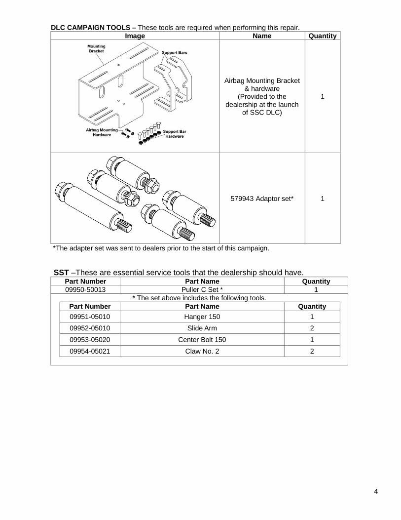
DLC CAMPAIGN TOOLS – These tools are required when performing this repair. Image Name Quantity
Airbag Mounting Bracket & hardware
(Provided to the dealership at the launch
of SSC DLC)
1
579943 Adaptor set* 1
*The adapter set was sent to dealers prior to the start of this campaign. SST –These are essential service tools that the dealership should have.
Part Number Part Name Quantity 09950-50013 Puller C Set * 1
* The set above includes the following tools. Part Number Part Name Quantity 09951-05010 Hanger 150 1 09952-05010 Slide Arm 2 09953-05020 Center Bolt 150 1 09954-05021 Claw No. 2 2
5
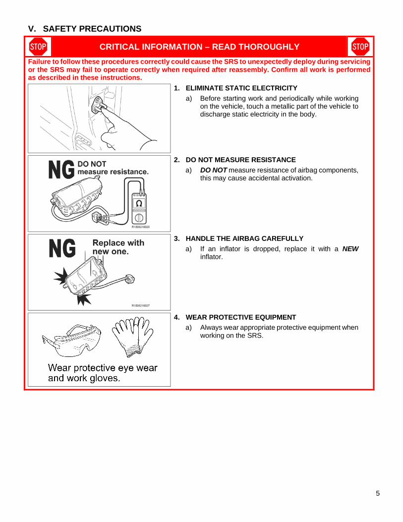
V. SAFETY PRECAUTIONS
CRITICAL INFORMATION – READ THOROUGHLY
Failure to follow these procedures correctly could cause the SRS to unexpectedly deploy during servicing or the SRS may fail to operate correctly when required after reassembly. Confirm all work is performed as described in these instructions.
1. ELIMINATE STATIC ELECTRICITY
a) Before starting work and periodically while working on the vehicle, touch a metallic part of the vehicle to discharge static electricity in the body.
2. DO NOT MEASURE RESISTANCE
a) DO NOT measure resistance of airbag components, this may cause accidental activation.
3. HANDLE THE AIRBAG CAREFULLY
a) If an inflator is dropped, replace it with a NEW inflator.
4. WEAR PROTECTIVE EQUIPMENT
a) Always wear appropriate protective equipment when working on the SRS.
6
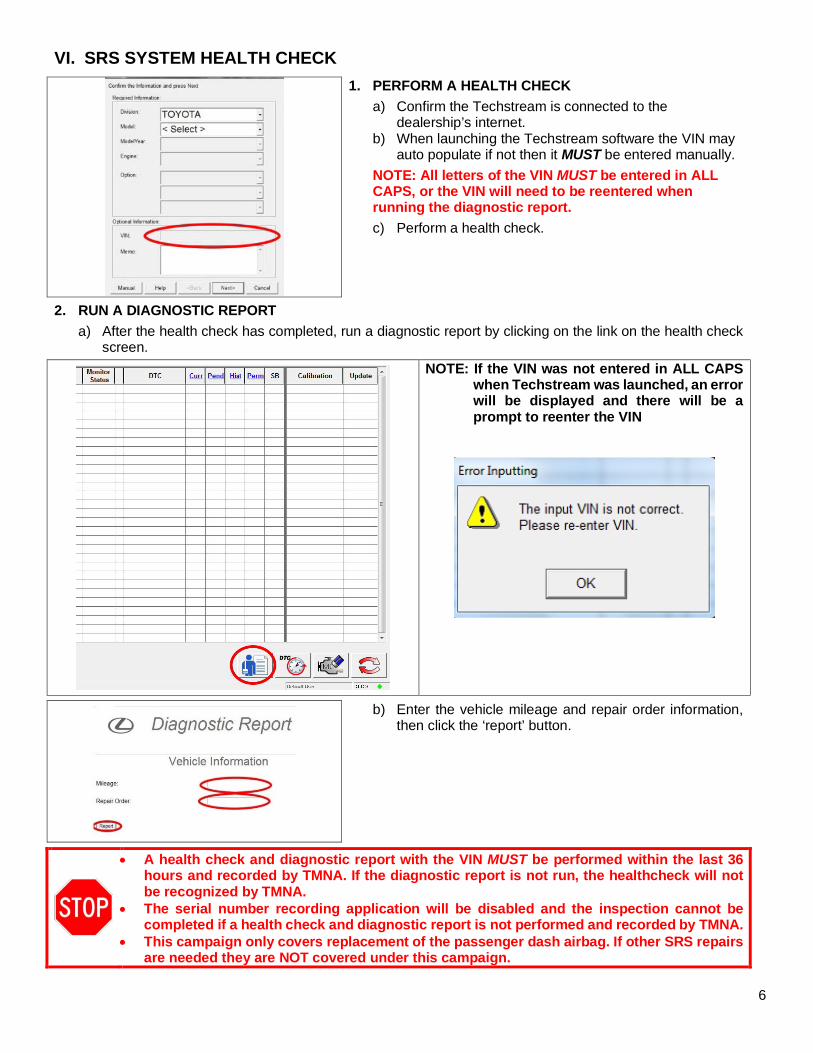
VI. SRS SYSTEM HEALTH CHECK
1. PERFORM A HEALTH CHECK
a) Confirm the Techstream is connected to the dealership’s internet.
b) When launching the Techstream software the VIN may auto populate if not then it MUST be entered manually.
NOTE: All letters of the VIN MUST be entered in ALL CAPS, or the VIN will need to be reentered when running the diagnostic report.
c) Perform a health check.
2. RUN A DIAGNOSTIC REPORT
a) After the health check has completed, run a diagnostic report by clicking on the link on the health check screen.
NOTE: If the VIN was not entered in ALL CAPS when Techstream was launched, an error will be displayed and there will be a prompt to reenter the VIN
b) Enter the vehicle mileage and repair order information, then click the ‘report’ button.
• A health check and diagnostic report with the VIN MUST be performed within the last 36 hours and recorded by TMNA. If the diagnostic report is not run, the healthcheck will not be recognized by TMNA.
• The serial number recording application will be disabled and the inspection cannot be completed if a health check and diagnostic report is not performed and recorded by TMNA.
• This campaign only covers replacement of the passenger dash airbag. If other SRS repairs are needed they are NOT covered under this campaign.
7
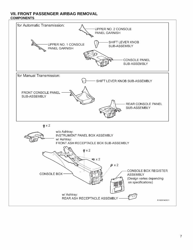
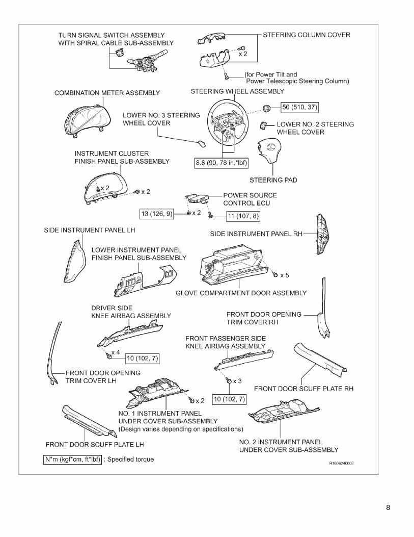
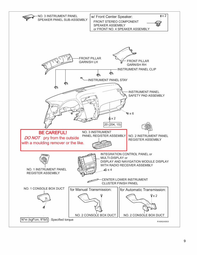
VII. FRONT PASSENGER AIRBAG REMOVAL COMPONENTS
8
9
10
11
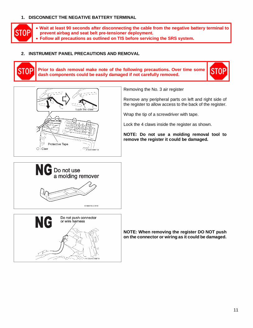
1. DISCONNECT THE NEGATIVE BATTERY TERMINAL
• Wait at least 90 seconds after disconnecting the cable from the negative battery terminal to prevent airbag and seat belt pre-tensioner deployment.
• Follow all precautions as outlined on TIS before servicing the SRS system.
2. INSTRUMENT PANEL PRECAUTIONS AND REMOVAL
Prior to dash removal make note of the following precautions. Over time some dash components could be easily damaged if not carefully removed.
Removing the No. 3 air register Remove any peripheral parts on left and right side of the register to allow access to the back of the register. Wrap the tip of a screwdriver with tape. Lock the 4 claws inside the register as shown. NOTE: Do not use a molding removal tool to remove the register it could be damaged.
NOTE: When removing the register DO NOT push on the connector or wiring as it could be damaged.
12
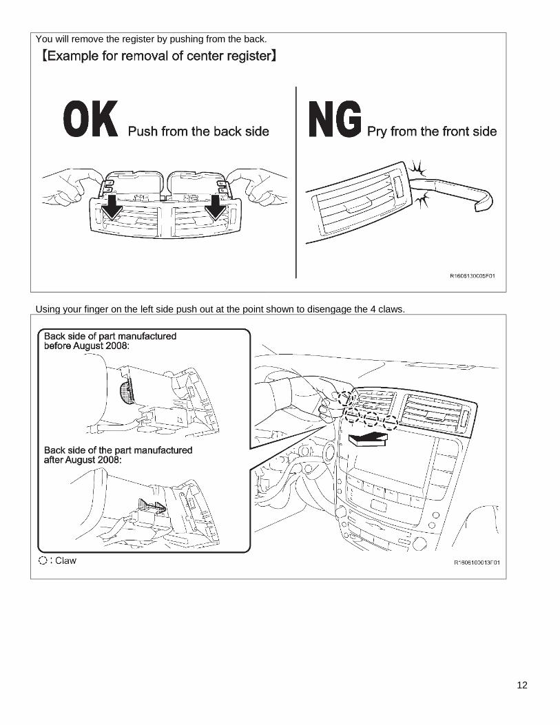
You will remove the register by pushing from the back.
Using your finger on the left side push out at the point shown to disengage the 4 claws.
13
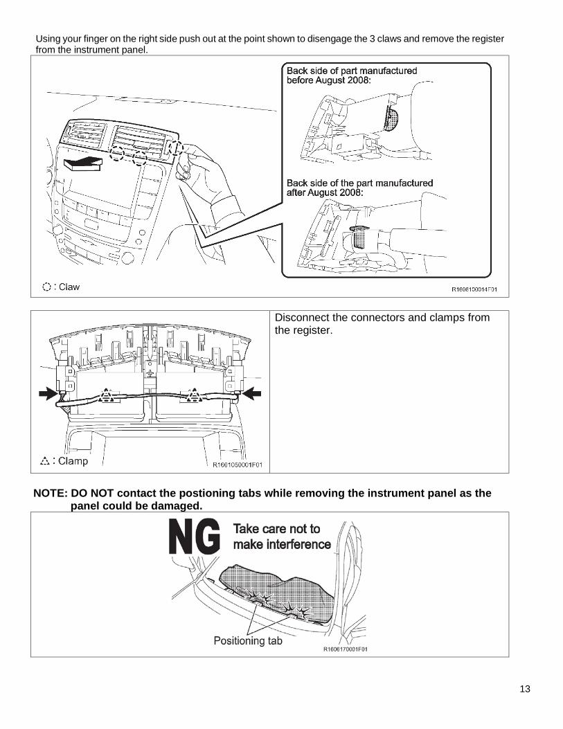
Using your finger on the right side push out at the point shown to disengage the 3 claws and remove the register from the instrument panel.
Disconnect the connectors and clamps from the register.
NOTE: DO NOT contact the postioning tabs while removing the instrument panel as the
panel could be damaged.
14
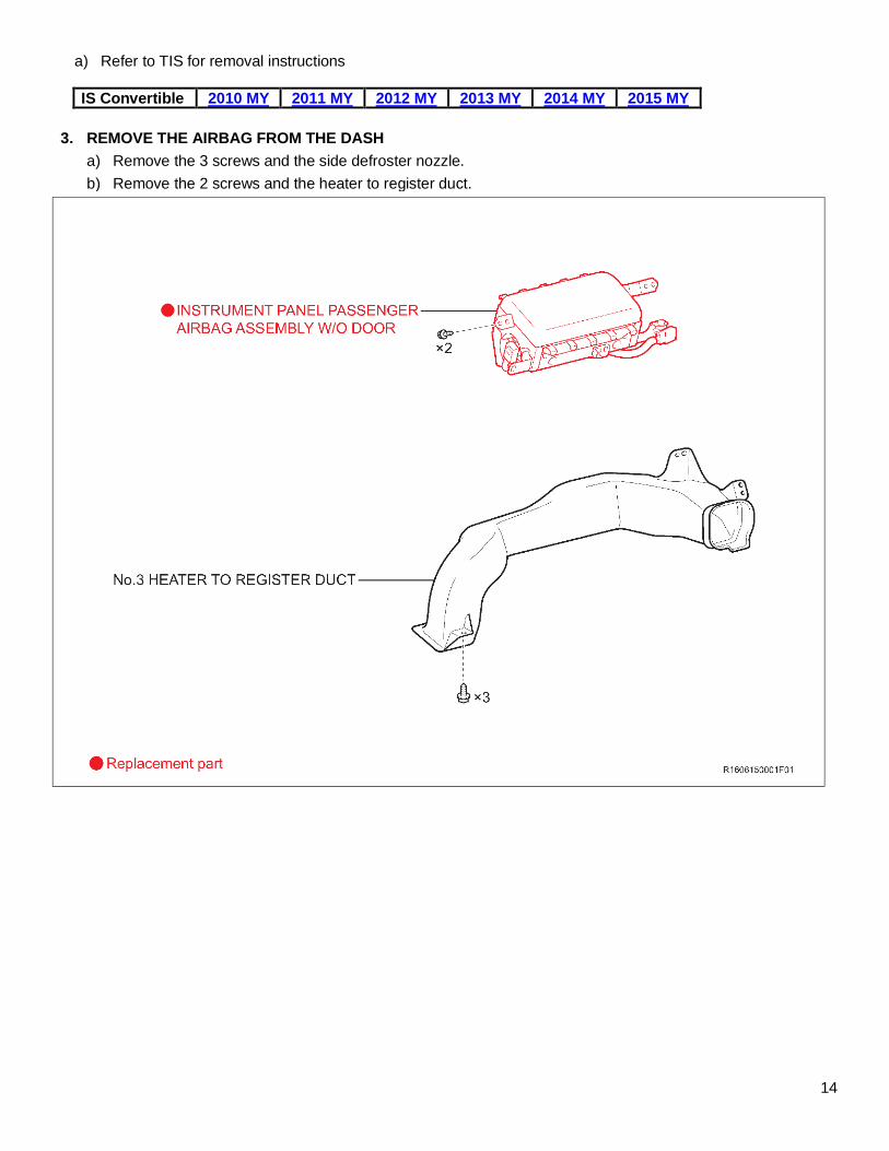
a) Refer to TIS for removal instructions
IS Convertible 2010 MY 2011 MY 2012 MY 2013 MY 2014 MY 2015 MY
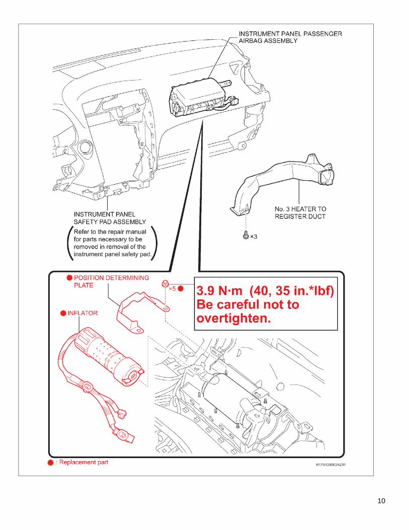
3. REMOVE THE AIRBAG FROM THE DASH
a) Remove the 3 screws and the side defroster nozzle.
b) Remove the 2 screws and the heater to register duct.
15
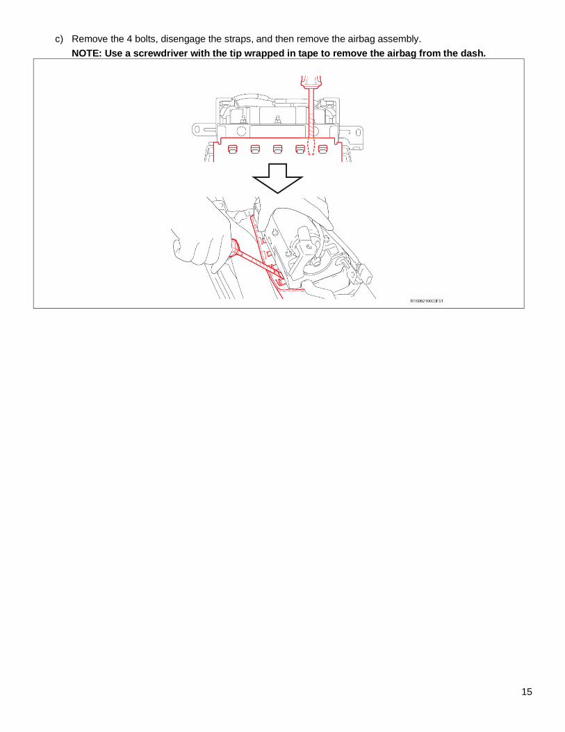
c) Remove the 4 bolts, disengage the straps, and then remove the airbag assembly.
NOTE: Use a screwdriver with the tip wrapped in tape to remove the airbag from the dash.
16
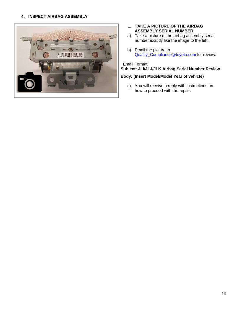
4. INSPECT AIRBAG ASSEMBLY
1. TAKE A PICTURE OF THE AIRBAG ASSEMBLY SERIAL NUMBER
a) Take a picture of the airbag assembly serial number exactly like the image to the left.
b) Email the picture to [email protected] for review.
Email Format Subject: JLI/JLJ/JLK Airbag Serial Number Review
Body: (Insert Model/Model Year of vehicle)
c) You will receive a reply with instructions on how to proceed with the repair.
17
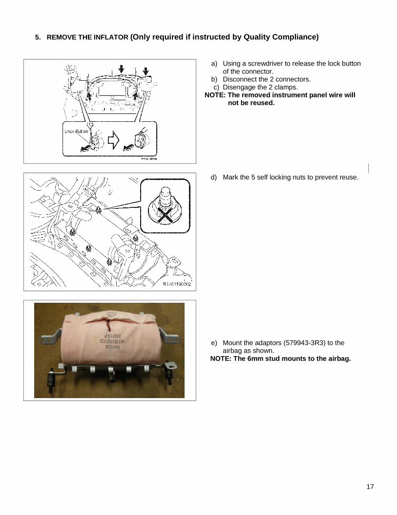
5. REMOVE THE INFLATOR (Only required if instructed by Quality Compliance)
a) Using a screwdriver to release the lock button of the connector.
b) Disconnect the 2 connectors. c) Disengage the 2 clamps.
NOTE: The removed instrument panel wire will not be reused.
d) Mark the 5 self locking nuts to prevent reuse.
e) Mount the adaptors (579943-3R3) to the airbag as shown.
NOTE: The 6mm stud mounts to the airbag.
18
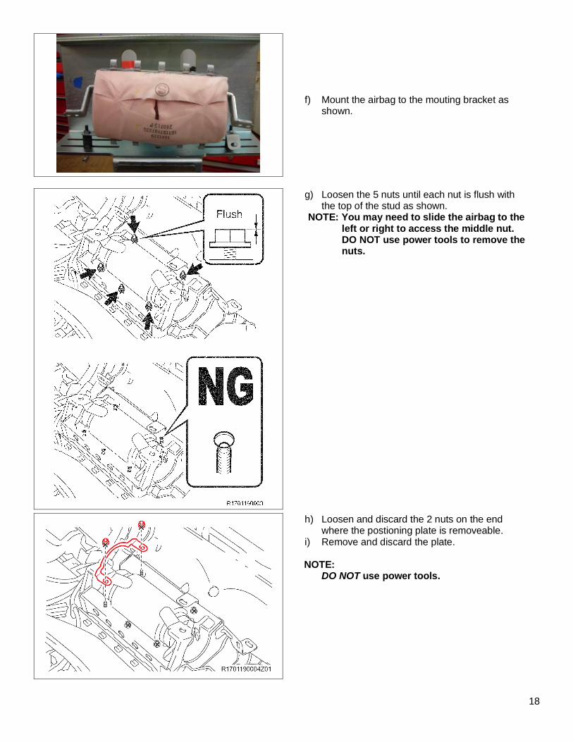
f) Mount the airbag to the mouting bracket as shown.
g) Loosen the 5 nuts until each nut is flush with the top of the stud as shown.
NOTE: You may need to slide the airbag to the left or right to access the middle nut. DO NOT use power tools to remove the nuts.
h) Loosen and discard the 2 nuts on the end where the postioning plate is removeable.
i) Remove and discard the plate.
NOTE: DO NOT use power tools.
19
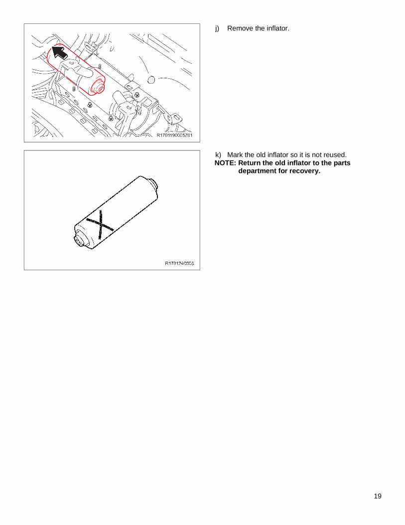
j) Remove the inflator.
k) Mark the old inflator so it is not reused. NOTE: Return the old inflator to the parts
department for recovery.
20
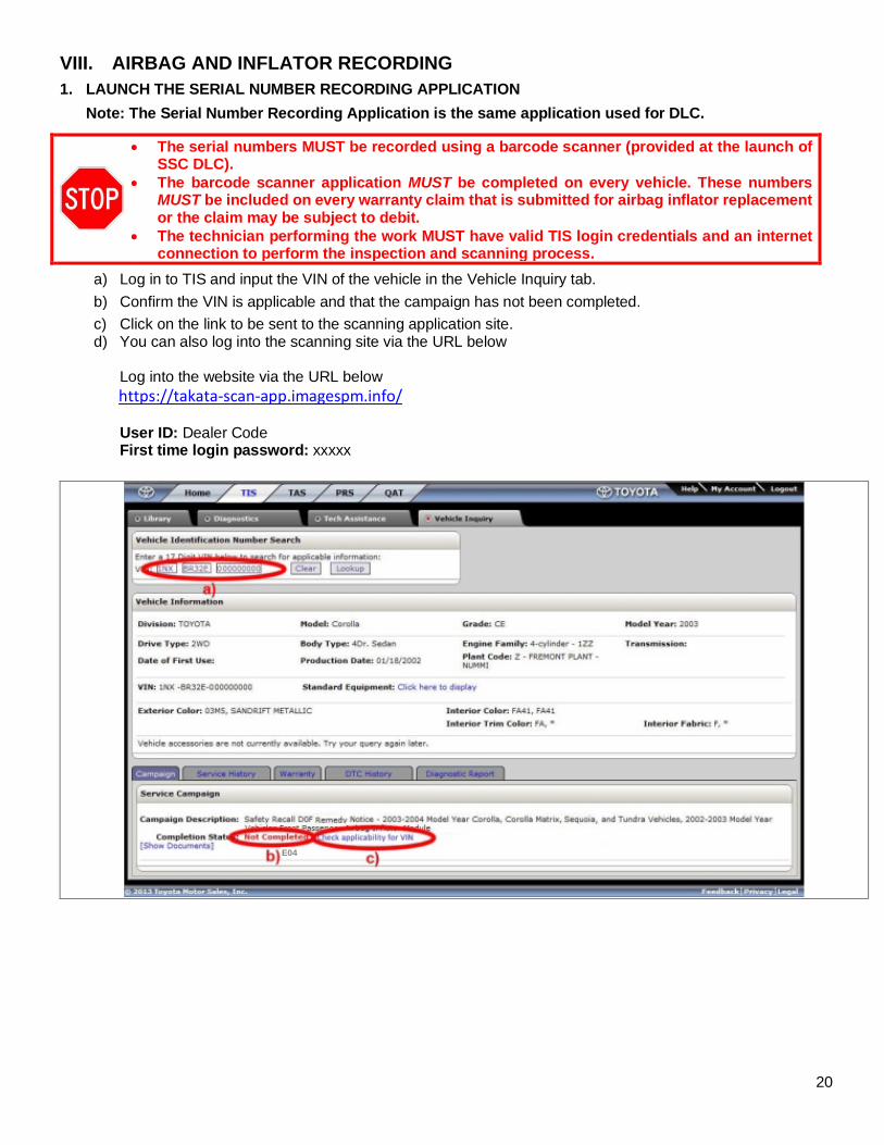
VIII. AIRBAG AND INFLATOR RECORDING
1. LAUNCH THE SERIAL NUMBER RECORDING APPLICATION
Note: The Serial Number Recording Application is the same application used for DLC.
• The serial numbers MUST be recorded using a barcode scanner (provided at the launch of SSC DLC).
• The barcode scanner application MUST be completed on every vehicle. These numbers MUST be included on every warranty claim that is submitted for airbag inflator replacement or the claim may be subject to debit.
• The technician performing the work MUST have valid TIS login credentials and an internet connection to perform the inspection and scanning process.
a) Log in to TIS and input the VIN of the vehicle in the Vehicle Inquiry tab.
b) Confirm the VIN is applicable and that the campaign has not been completed.
c) Click on the link to be sent to the scanning application site. d) You can also log into the scanning site via the URL below
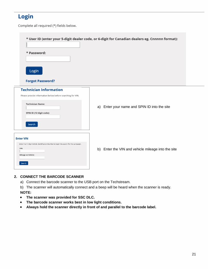
Log into the website via the URL below
https://takata-scan-app.imagespm.info/ User ID: Dealer Code First time login password: xxxxx
E04
21
a) Enter your name and SPIN ID into the site
b) Enter the VIN and vehicle mileage into the site
2. CONNECT THE BARCODE SCANNER
a) Connect the barcode scanner to the USB port on the Techstream.
b) The scanner will automatically connect and a beep will be heard when the scanner is ready.
NOTE: • The scanner was provided for SSC DLC. • The barcode scanner works best in low light conditions. • Always hold the scanner directly in front of and parallel to the barcode label.
22
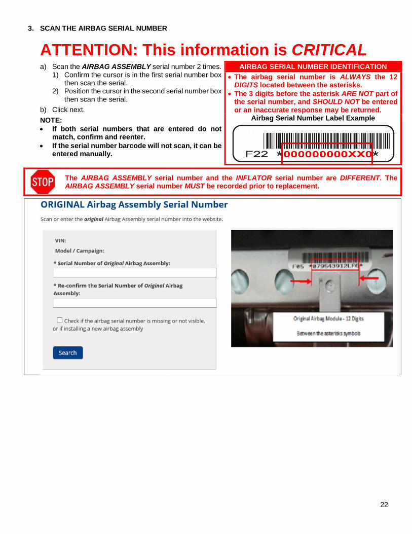
3. SCAN THE AIRBAG SERIAL NUMBER
ATTENTION: This information is CRITICAL
a) Scan the AIRBAG ASSEMBLY serial number 2 times. 1) Confirm the cursor is in the first serial number box
then scan the serial. 2) Position the cursor in the second serial number box
then scan the serial.
b) Click next.
NOTE: • If both serial numbers that are entered do not
match, confirm and reenter. • If the serial number barcode will not scan, it can be
entered manually.
AIRBAG SERIAL NUMBER IDENTIFICATION • The airbag serial number is ALWAYS the 12
DIGITS located between the asterisks. • The 3 digits before the asterisk ARE NOT part of
the serial number, and SHOULD NOT be entered or an inaccurate response may be returned.
Airbag Serial Number Label Example
The AIRBAG ASSEMBLY serial number and the INFLATOR serial number are DIFFERENT. The AIRBAG ASSEMBLY serial number MUST be recorded prior to replacement.
23
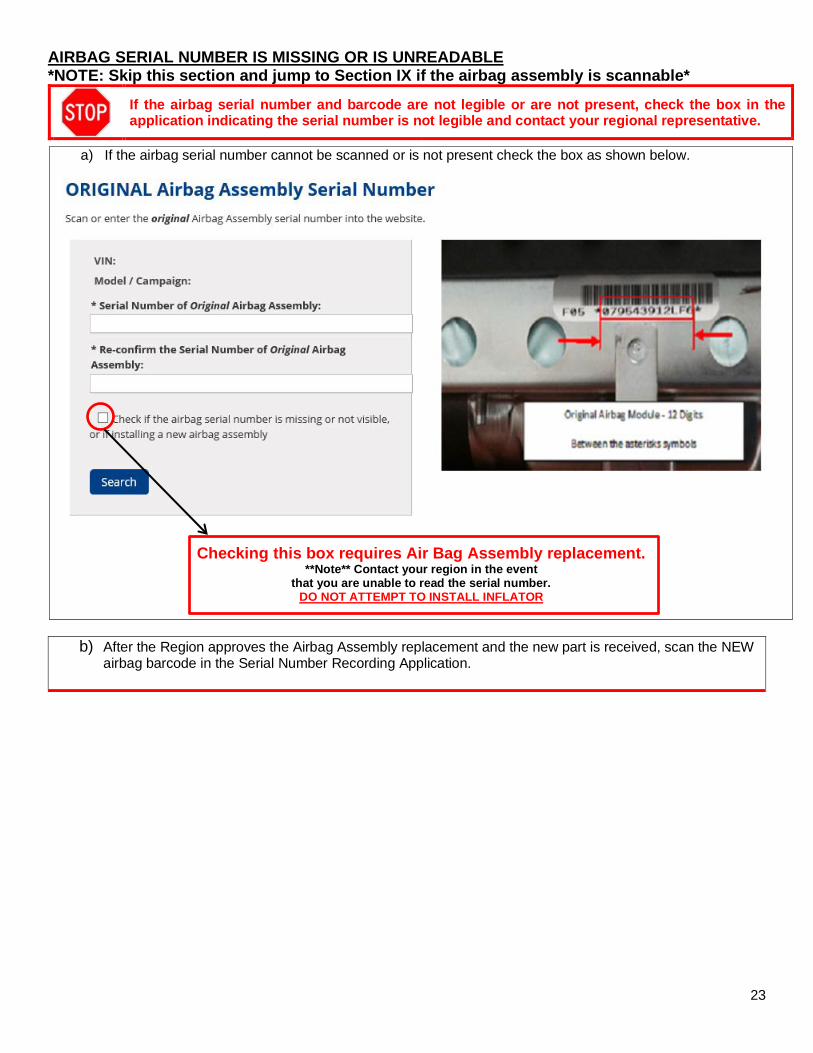
AIRBAG SERIAL NUMBER IS MISSING OR IS UNREADABLE *NOTE: Skip this section and jump to Section IX if the airbag assembly is scannable*
If the airbag serial number and barcode are not legible or are not present, check the box in the application indicating the serial number is not legible and contact your regional representative.
a) If the airbag serial number cannot be scanned or is not present check the box as shown below.
Checking this box requires Air Bag Assembly replacement. **Note** Contact your region in the event
that you are unable to read the serial number. DO NOT ATTEMPT TO INSTALL INFLATOR
b) After the Region approves the Airbag Assembly replacement and the new part is received, scan the NEW airbag barcode in the Serial Number Recording Application.
24
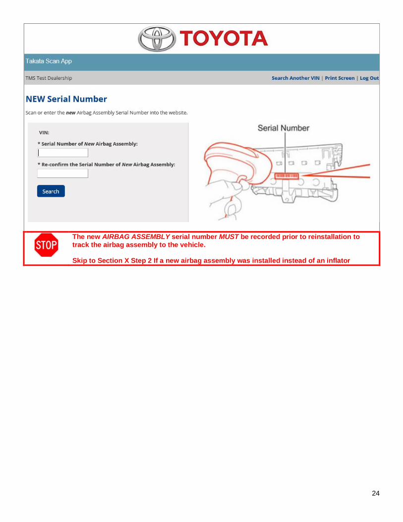
The new AIRBAG ASSEMBLY serial number MUST be recorded prior to reinstallation to track the airbag assembly to the vehicle. Skip to Section X Step 2 If a new airbag assembly was installed instead of an inflator
25
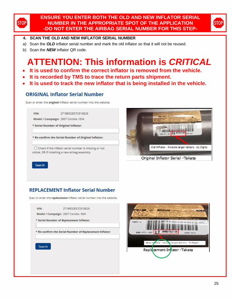
ENSURE YOU ENTER BOTH THE OLD AND NEW INFLATOR SERIAL NUMBER IN THE APPROPRIATE SPOT OF THE APPLICATION
-DO NOT ENTER THE AIRBAG SERIAL NUMBER FOR THIS STEP-
4. SCAN THE OLD AND NEW INFLATOR SERIAL NUMBER
a) Scan the OLD inflator serial number and mark the old inflator so that it will not be reused.
b) Scan the NEW inflator QR code.
ATTENTION: This information is CRITICAL • It is used to confirm the correct inflator is removed from the vehicle. • It is recorded by TMS to trace the return parts shipment. • It is used to track the new inflator that is being installed in the vehicle.
26
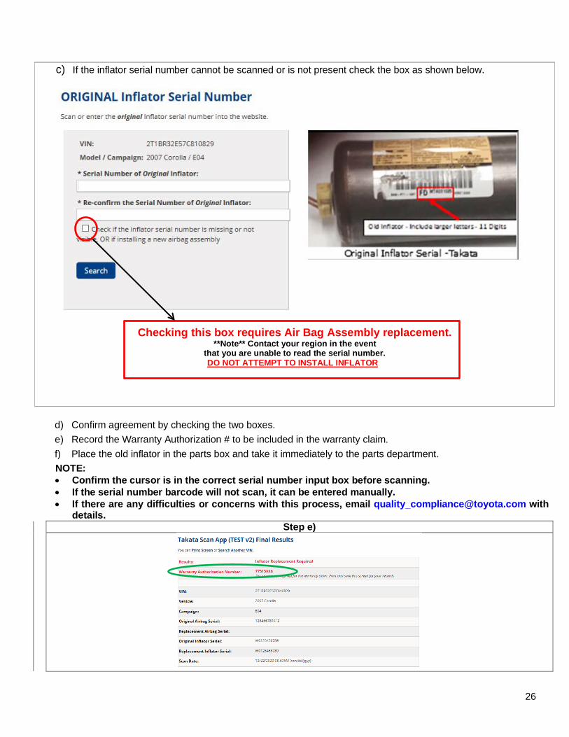
c) If the inflator serial number cannot be scanned or is not present check the box as shown below.
Checking this box requires Air Bag Assembly replacement. **Note** Contact your region in the event
that you are unable to read the serial number. DO NOT ATTEMPT TO INSTALL INFLATOR
d) Confirm agreement by checking the two boxes.
e) Record the Warranty Authorization # to be included in the warranty claim.
f) Place the old inflator in the parts box and take it immediately to the parts department.
NOTE: • Confirm the cursor is in the correct serial number input box before scanning. • If the serial number barcode will not scan, it can be entered manually. • If there are any difficulties or concerns with this process, email [email protected] with
details. Step e)
27
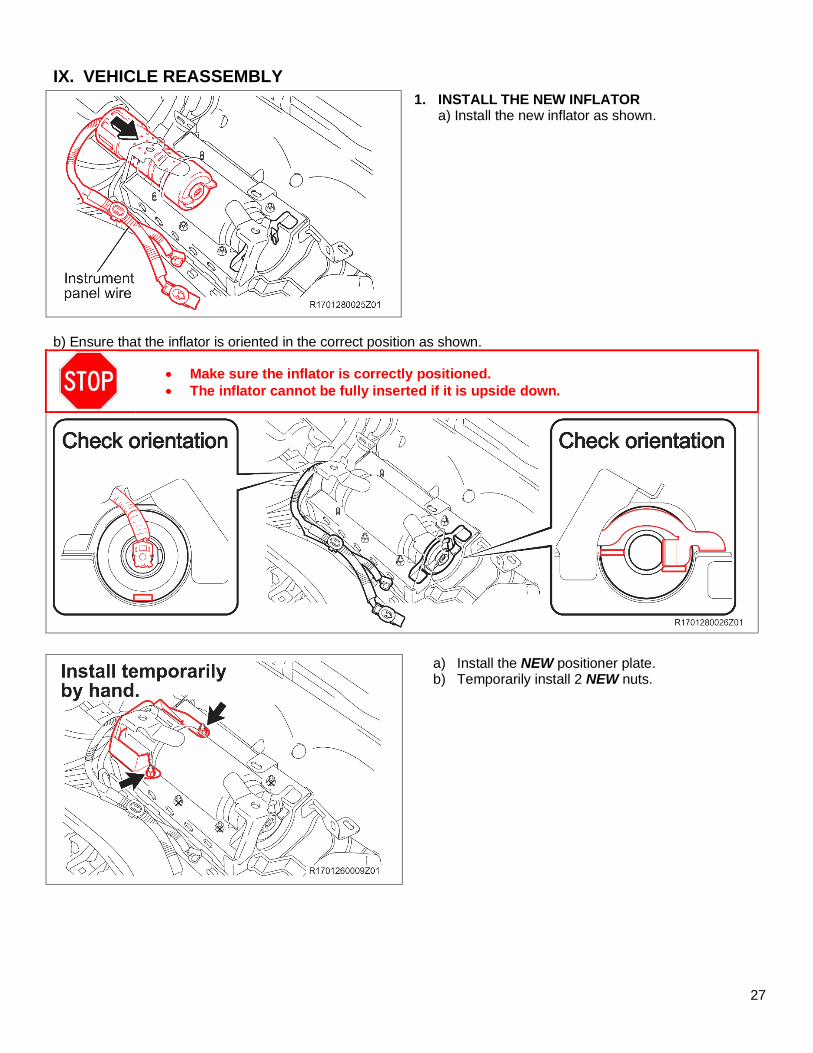
IX. VEHICLE REASSEMBLY
1. INSTALL THE NEW INFLATOR a) Install the new inflator as shown.
b) Ensure that the inflator is oriented in the correct position as shown.
• Make sure the inflator is correctly positioned. • The inflator cannot be fully inserted if it is upside down.
a) Install the NEW positioner plate. b) Temporarily install 2 NEW nuts.
28
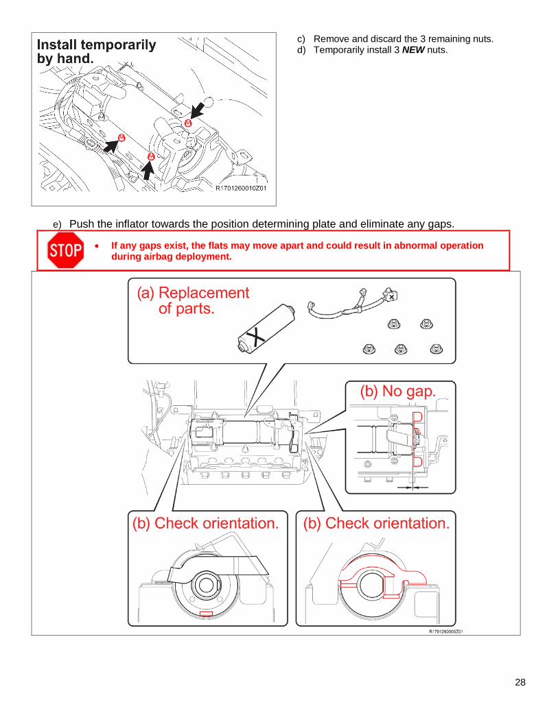
c) Remove and discard the 3 remaining nuts. d) Temporarily install 3 NEW nuts.
e) Push the inflator towards the position determining plate and eliminate any gaps.
• If any gaps exist, the flats may move apart and could result in abnormal operation during airbag deployment.
29
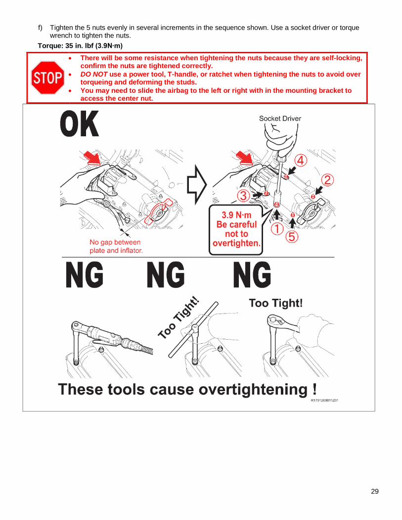
f) Tighten the 5 nuts evenly in several increments in the sequence shown. Use a socket driver or torque wrench to tighten the nuts.
Torque: 35 in. lbf (3.9N∙m)
• There will be some resistance when tightening the nuts because they are self-locking, confirm the nuts are tightened correctly.
• DO NOT use a power tool, T-handle, or ratchet when tightening the nuts to avoid over torqueing and deforming the studs.
• You may need to slide the airbag to the left or right with in the mounting bracket to access the center nut.
30
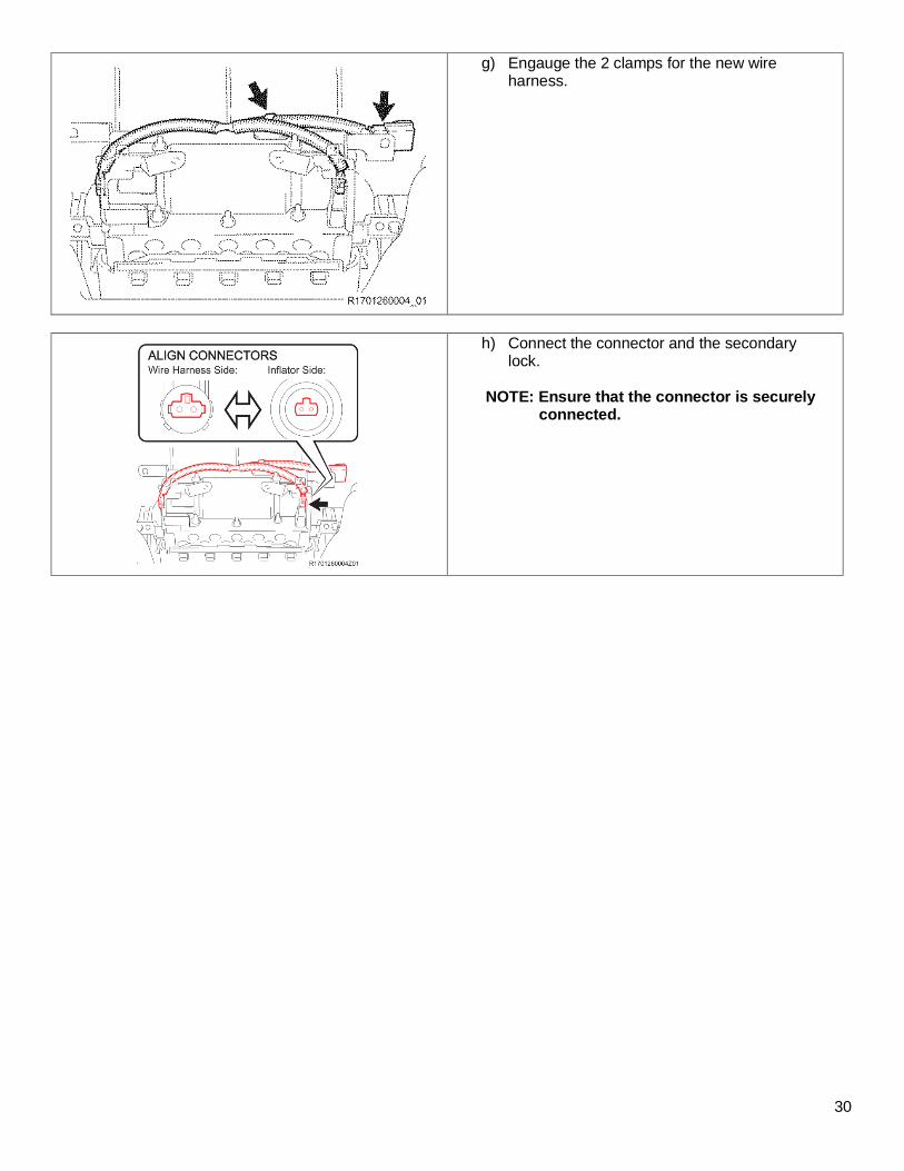
g) Engauge the 2 clamps for the new wire harness.
h) Connect the connector and the secondary lock.
NOTE: Ensure that the connector is securely connected.
31
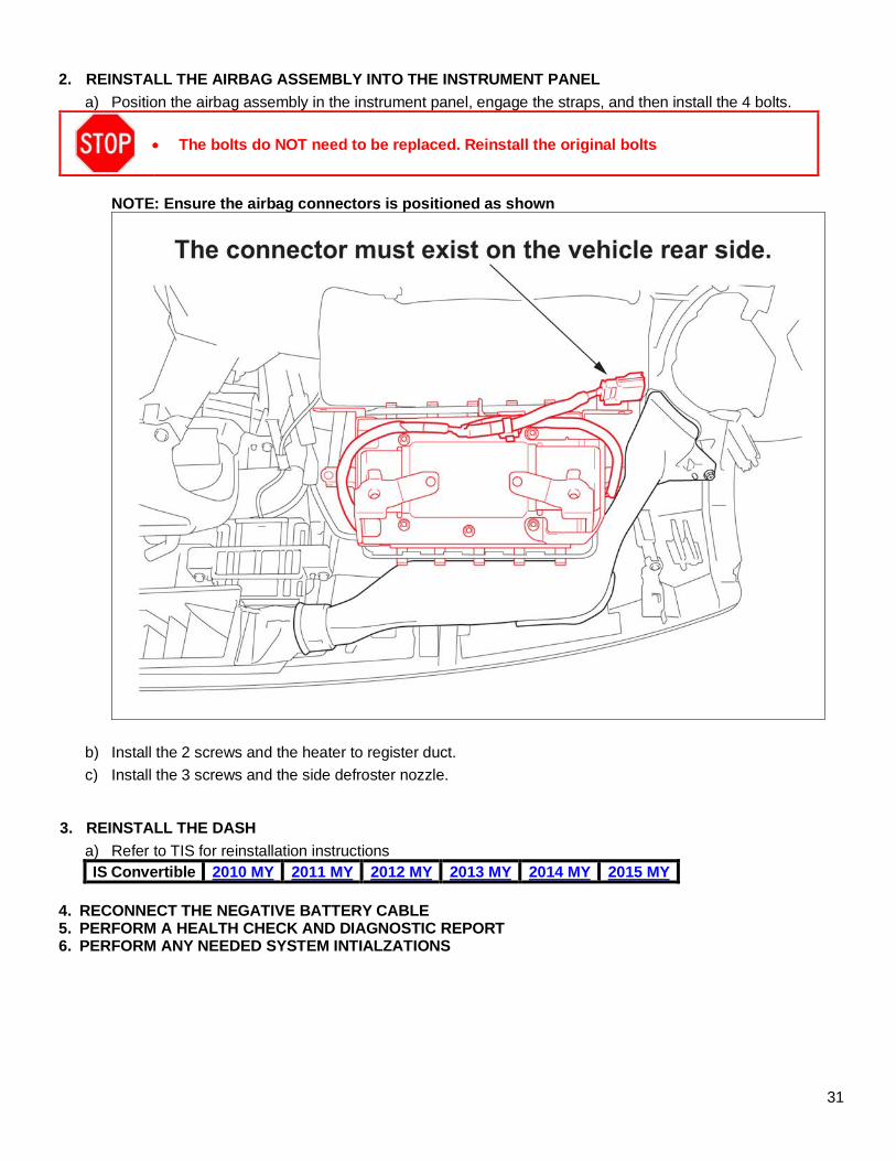
2. REINSTALL THE AIRBAG ASSEMBLY INTO THE INSTRUMENT PANEL
a) Position the airbag assembly in the instrument panel, engage the straps, and then install the 4 bolts.
• The bolts do NOT need to be replaced. Reinstall the original bolts
NOTE: Ensure the airbag connectors is positioned as shown
b) Install the 2 screws and the heater to register duct.
c) Install the 3 screws and the side defroster nozzle.
3. REINSTALL THE DASH
a) Refer to TIS for reinstallation instructions IS Convertible 2010 MY 2011 MY 2012 MY 2013 MY 2014 MY 2015 MY
4. RECONNECT THE NEGATIVE BATTERY CABLE 5. PERFORM A HEALTH CHECK AND DIAGNOSTIC REPORT 6. PERFORM ANY NEEDED SYSTEM INTIALZATIONS
32
◄ VERIFY REPAIR QUALITY ► − Confirm all precautions are followed to ensure safety during the repair − Confirm the entire serial number checker application is completed and the warranty authorization #
is recorded on EVERY vehicle − Confirm the old inflator is handled safely and given to the appropriate parts professional for
shipment
If you have any questions regarding this update, please contact your area representative.
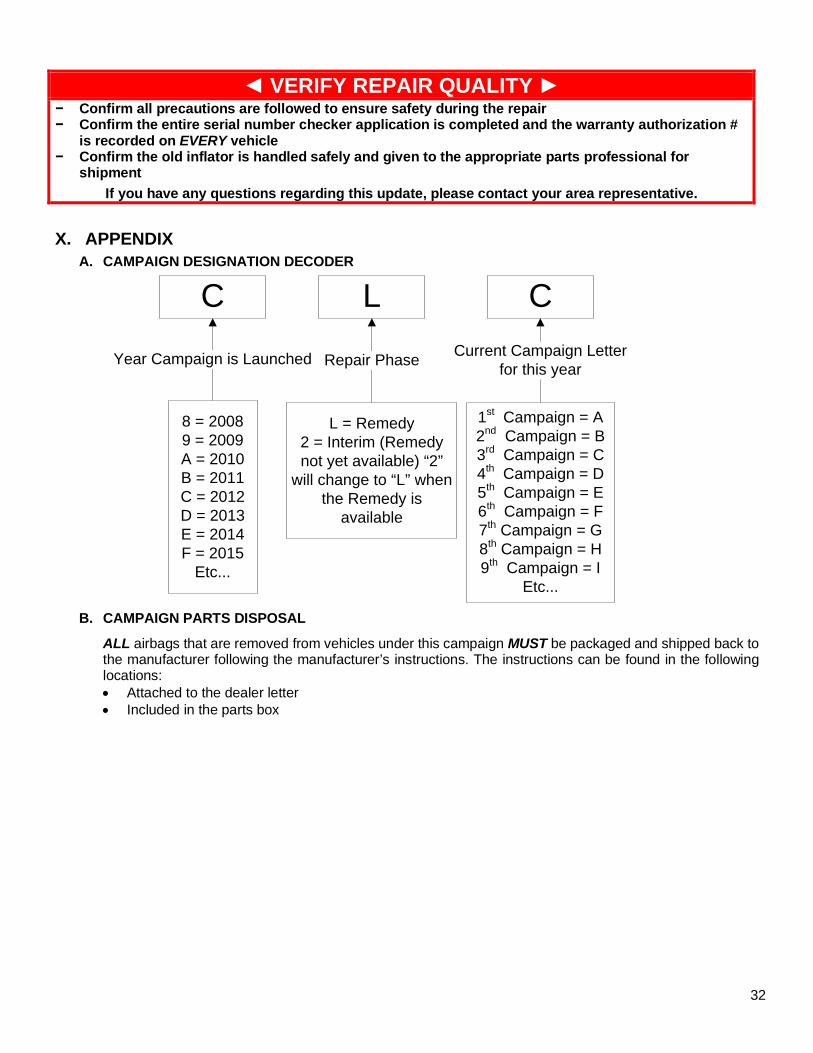
X. APPENDIX
A. CAMPAIGN DESIGNATION DECODER
C L C
Year Campaign is Launched
8 = 20089 = 2009A = 2010B = 2011C = 2012 D = 2013E = 2014F = 2015
Etc...
Repair Phase
1st Campaign = A2nd Campaign = B3rd Campaign = C4th Campaign = D5th Campaign = E6th Campaign = F7th Campaign = G8th Campaign = H9th Campaign = I
Etc...
Current Campaign Letter for this year
L = Remedy2 = Interim (Remedy not yet available) “2”
will change to “L” when the Remedy is
available
B. CAMPAIGN PARTS DISPOSAL
ALL airbags that are removed from vehicles under this campaign MUST be packaged and shipped back to the manufacturer following the manufacturer’s instructions. The instructions can be found in the following locations: • Attached to the dealer letter • Included in the parts box