Embed Size (px)
Citation preview
TECHNICAL INSTRUCTIONS
FOR
SAFETY RECALL C0U
HYBRID ELECTRIC WATER PUMP REPLACEMENT
2004 – CERTAIN 2009 MODEL YEAR PRIUS
2
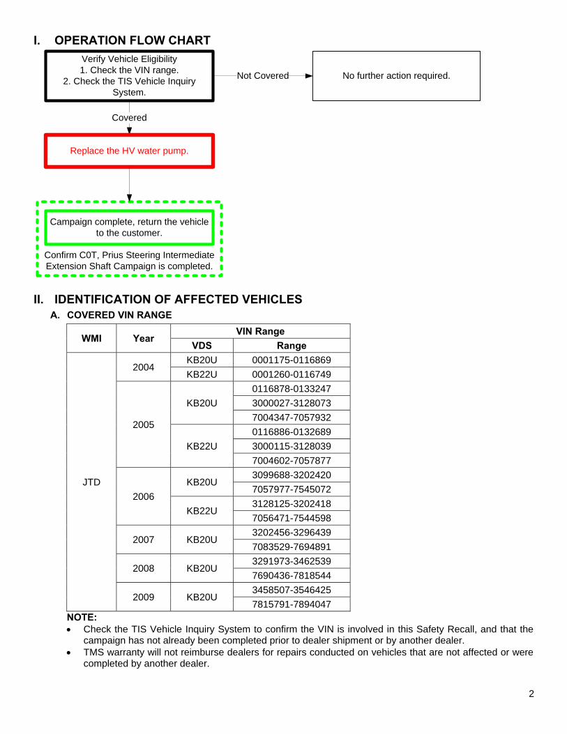
I. OPERATION FLOW CHART
Confirm C0T, Prius Steering Intermediate Extension Shaft Campaign is completed.
Verify Vehicle Eligibility1. Check the VIN range.
2. Check the TIS Vehicle Inquiry System.
No further action required.Not Covered
Campaign complete, return the vehicle to the customer.
Covered
Replace the HV water pump.
II. IDENTIFICATION OF AFFECTED VEHICLES
A. COVERED VIN RANGE
WMI Year VIN Range
VDS Range
JTD
2004 KB20U 0001175-0116869 KB22U 0001260-0116749
2005
KB20U 0116878-0133247 3000027-3128073 7004347-7057932
KB22U 0116886-0132689 3000115-3128039 7004602-7057877
2006 KB20U
3099688-3202420 7057977-7545072
KB22U 3128125-3202418 7056471-7544598
2007 KB20U 3202456-3296439 7083529-7694891
2008 KB20U 3291973-3462539 7690436-7818544
2009 KB20U 3458507-3546425 7815791-7894047
NOTE: • Check the TIS Vehicle Inquiry System to confirm the VIN is involved in this Safety Recall, and that the
campaign has not already been completed prior to dealer shipment or by another dealer. • TMS warranty will not reimburse dealers for repairs conducted on vehicles that are not affected or were
completed by another dealer.
3
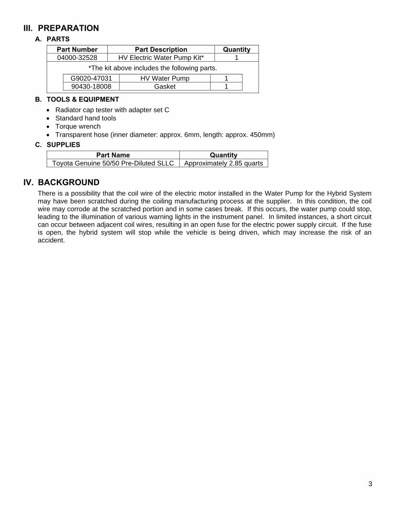
III. PREPARATION
A. PARTS
Part Number Part Description Quantity 04000-32528 HV Electric Water Pump Kit* 1
*The kit above includes the following parts.
G9020-47031 HV Water Pump 1 90430-18008 Gasket 1
B. TOOLS & EQUIPMENT
• Radiator cap tester with adapter set C • Standard hand tools • Torque wrench • Transparent hose (inner diameter: approx. 6mm, length: approx. 450mm)
C. SUPPLIES
Part Name Quantity Toyota Genuine 50/50 Pre-Diluted SLLC Approximately 2.85 quarts
IV. BACKGROUND
There is a possibility that the coil wire of the electric motor installed in the Water Pump for the Hybrid System may have been scratched during the coiling manufacturing process at the supplier. In this condition, the coil wire may corrode at the scratched portion and in some cases break. If this occurs, the water pump could stop, leading to the illumination of various warning lights in the instrument panel. In limited instances, a short circuit can occur between adjacent coil wires, resulting in an open fuse for the electric power supply circuit. If the fuse is open, the hybrid system will stop while the vehicle is being driven, which may increase the risk of an accident.
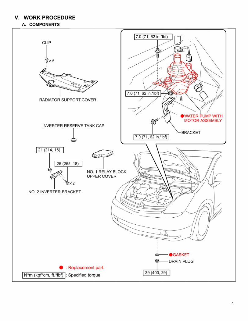
V.
A
WORK PRA. COMPON
ROCEDURNENTS
RE
44
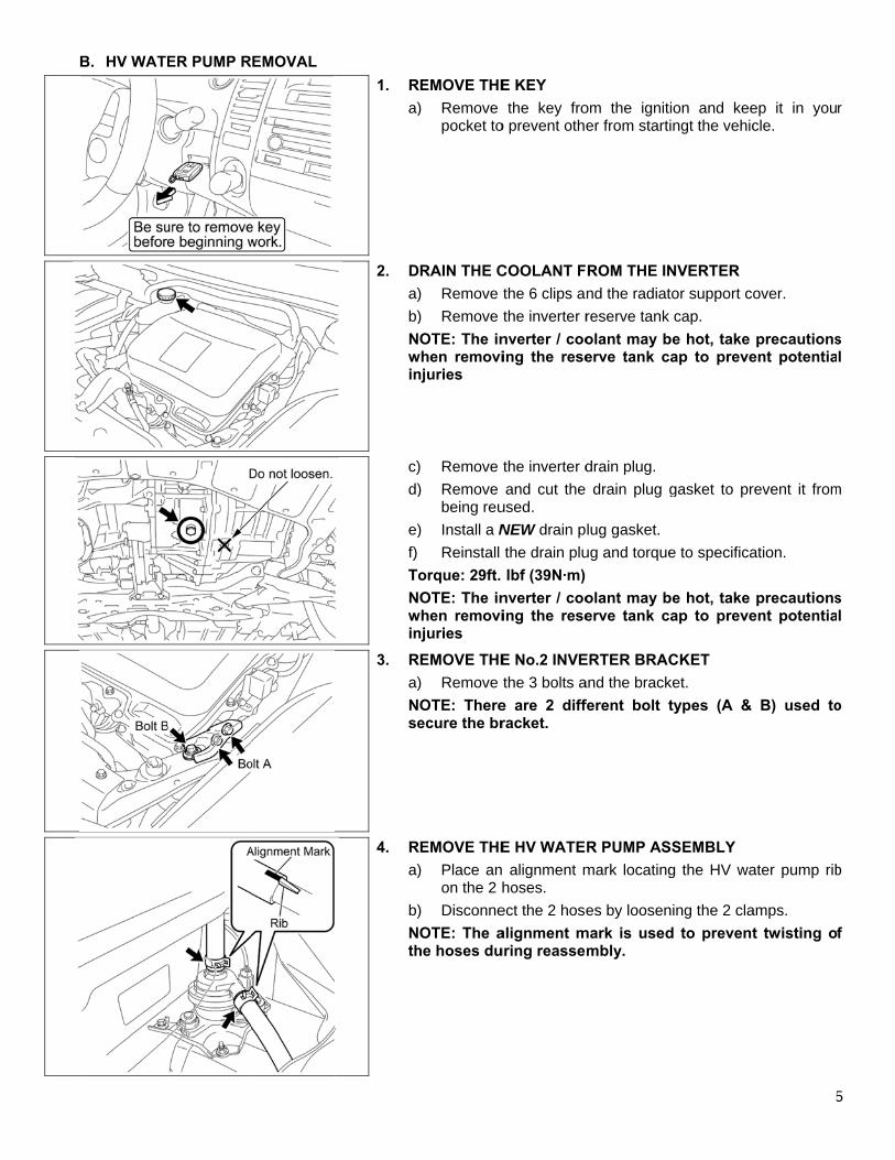
B
B. HV WATEER PUMP R
REMOVAL
1. R
a)
2. D
a)b)Nwin
c)d)
e)
f)
To
Nwin
3. R
a)
Nse
4. R
a)
b)
Nth
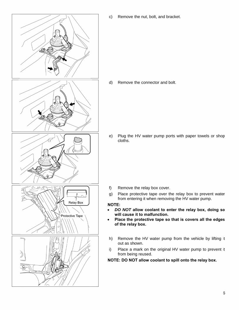
REMOVE THE) Remove
pocket to
RAIN THE C) Remove
) Remove
OTE: The inwhen removinjuries
) Remove
) Remove being reu
) Install a NReinstall
orque: 29ft. OTE: The in
when removinjuries
REMOVE THE) Remove OTE: Thereecure the br
REMOVE THE) Place an
on the 2 h
) DisconneOTE: The a
he hoses du
E KEY the key fro
o prevent othe
COOLANT Fthe 6 clips athe inverter rnverter / cooing the rese
the inverter dand cut the
used. NEW drain pthe drain plulbf (39N·m)
nverter / cooing the rese
E No.2 INVEthe 3 bolts a
e are 2 diffracket.
E HV WATE alignment mhoses.
ect the 2 hosealignment muring reasse
om the igniter from starti
ROM THE INnd the radiatreserve tank olant may berve tank c
drain plug. drain plug g
lug gasket. ug and torque
olant may berve tank c
ERTER BRACand the brackferent bolt t
R PUMP ASmark locating
es by loosenmark is used
mbly.
ion and keeingt the vehic
NVERTER tor support cocap.
be hot, take ap to preve
gasket to pr
e to specifica
be hot, take ap to preve
CKET ket. types (A &
SSEMBLY g the HV wa
ning the 2 clad to prevent
5
ep it in youcle.
over.
precautionsent potentia
revent it from
ation.
precautionsent potentia
B) used to
ater pump rib
amps. t twisting o
5
r
s l
m
s l
o
b
f
c)
d)
e)
f)g)
NO•
•
h)
i)
NO
) Remove
) Remove
) Plug the cloths.
Remove
) Place profrom ente
OTE: DO NOT awill cause Place the of the rela
) Remove out as sh
Place a mfrom bein
OTE: DO NO
the nut, bolt,
the connecto
HV water pu
the relay boxotective tapeering it when
allow coolan it to malfunprotective t
ay box.
the HV watehown. mark on the ng reused. OT allow coo
, and bracket
or and bolt.
ump ports w
x cover. e over the re
removing th
nt to enter tnction. tape so that
er pump from
original HV
olant to spill
t.
with paper tow
elay box to pe HV water p
the relay bo
t is covers a
m the vehicl
water pump
l onto the re
6
wels or shop
prevent watepump.
ox, doing so
all the edges
le by lifting i
to prevent i
elay box.
6
p
r
o
s
t
t
C
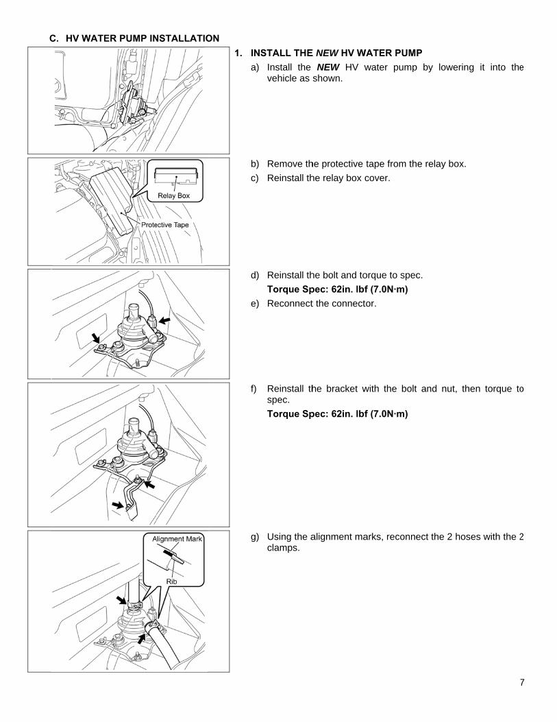
C. HV WATEER PUMP IN
NSTALLATIO
ON 1. IN
a)
b)c)
d)
e)
f)
g)
STALL THEInstall the vehicle as
Remove th
Reinstall th
Reinstall thTorque SpReconnect
Reinstall thspec. Torque Sp
Using the aclamps.
E NEW HV WNEW HV w
shown.
he protective he relay box c
he bolt and topec: 62in. lbft the connect
he bracket w
pec: 62in. lbf
alignment ma
WATER PUMPwater pump
tape from thcover.
orque to specf (7.0N·m) tor.
with the bolt
f (7.0N·m)
arks, reconne
P p by lowerin
e relay box.
c.
and nut, th
ect the 2 hos
7
g it into the
hen torque to
ses with the 2
7
e
o
2
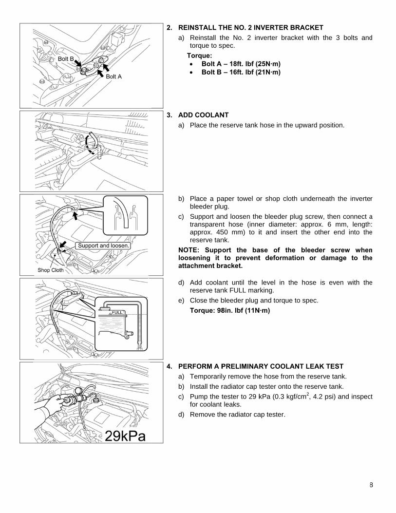
2. RE
a)
3. AD
a)
b)
c)
NOlooatt
d)
e)
4. PE
a)b)
c)
d)
EINSTALL TReinstall thtorque to s
Torque: • Bolt A • Bolt B
DD COOLANPlace the r
Place a pableeder pluSupport antransparenapprox. 45reserve tan
OTE: Suppoosening it tachment br
Add coolareserve tan
Close the bTorque: 98
ERFORM A PTemporaril
Install the rPump the tfor coolant Remove th
THE NO. 2 INhe No. 2 inpec.
– 18ft. lbf (2– 16ft. lbf (2
NT reserve tank
aper towel oug. nd loosen thet hose (inne
50 mm) to ink. ort the bato prevent
racket.
nt until the nk FULL marbleeder plug 8in. lbf (11N
PRELIMINARy remove theradiator cap ttester to 29 kleaks.
he radiator ca
NVERTER BRnverter brack
25N·m) 21N·m)
hose in the u
or shop cloth
e bleeder pluer diameter:it and insert
ase of the t deformati
level in therking. and torque t
N·m)
RY COOLANe hose from ttester onto thkPa (0.3 kgf/
ap tester.
RACKET ket with the
upward posit
h underneath
ug screw, the: approx. 6 t the other
bleeder son or dam
e hose is ev
to spec.
NT LEAK TEthe reserve the reserve ta/cm2, 4.2 psi
8
3 bolts and
tion.
h the inverte
en connect amm, lengthend into the
screw whenmage to the
ven with the
EST tank. ank. ) and inspec
8
d
r
a :
e
n e
e
ct
c
d
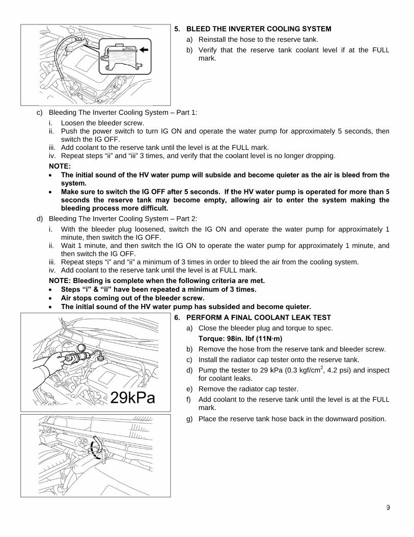
c) Bleeding i. Looseii. Push
switchiii. Add civ. RepeNOTE: • The i
syste• Make
secobleed
d) Bleeding i. With
minutii. Wait
then siii. Repeiv. Add cNOTE: B• Steps• Air st• The i
The Inverteren the bleedethe power s
h the IG OFFcoolant to theeat steps “ii” a
nitial sound em. e sure to swinds the resding processThe Inverterthe bleeder
te, then switc1 minute, answitch the IG
eat steps “i” acoolant to the
Bleeding is cs “i” & “ii” htops comingnitial sound
r Cooling Syser screw. switch to turnF. e reserve tanand “iii” 3 tim
of the HV w
itch the IG Oserve tank s more difficr Cooling Sys
plug loosench the IG OFnd then switcG OFF. and “ii” a minie reserve tancomplete whhave been reg out of the d of the HV w
5. BL
a)b)
stem – Part 1
n IG ON and
nk until the lees, and verif
water pump w
OFF after 5 smay becomcult. stem – Part 2ned, switch tF. ch the IG ON
imum of 3 timnk until the lehen the followepeated a mbleeder scre
water pump
6. PE
a)
b)c)
d)
e)f)
g)
LEED THE INReinstall th
Verify thatmark.
1:
d operate the
vel is at the Ffy that the co
will subside
seconds. If tme empty, a
2: the IG ON a
N to operate
mes in order vel is at FULwing criteriainimum of 3ew. has subside
ERFORM A FClose the bTorque: 98
Remove th
Install the rPump the tfor coolant Remove th
Add coolanmark. Place the r
NVERTER Che hose to tht the reserve
e water pum
FULL mark. oolant level is
and become
the HV wateallowing air
and operate
the water p
to bleed the LL mark. a are met. 3 times.
ed and becoFINAL COOLbleeder plug 8in. lbf (11Nhe hose from radiator cap ttester to 29 kleaks.
he radiator cant to the rese
reserve tank
COOLING SYe reserve tane tank coola
mp for approx
s no longer d
e quieter as
er pump is or to enter t
the water p
ump for app
air from the
ome quieter.LANT LEAKand torque t
N·m) the reserve
tester onto thkPa (0.3 kgf/
ap tester. erve tank unt
hose back in
YSTEM nk. ant level if
ximately 5 s
ropping.
the air is ble
operated for the system
ump for app
proximately 1
cooling syste
. K TEST to spec.
tank and blehe reserve ta/cm2, 4.2 psi
til the level is
n the downwa
9
at the FULL
econds, then
eed from the
more than 5making the
proximately 1
minute, and
em.
eeder screw.ank. ) and inspec
s at the FULL
ard position.
9
L
n
e
5 e
1
d
ct
L
− C− C− C
VI.
A
Confirm the Confirm therConfirm C0T
If you ha
APPENDIA. CAMPAIG
As requirvehicle arreturn.
coolant is fre are no coT, Prius Stee
ave any ques
IX GN PARTS Ded by Federare disposed o
◄ VEilled and bleolant leaks
ering Interm
stions regar
DISPOSAL al Regulationof in a manne
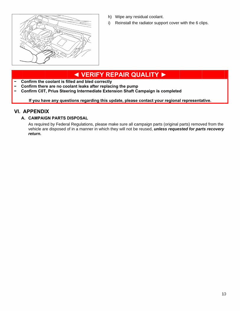
h)i)
RIFY REed correctlyafter replacediate Exten
rding this up
ns, please maer in which th
Wipe any r
Reinstall th
EPAIR Qing the pumnsion Shaft
pdate, pleas
ake sure all chey will not b
residual coolahe radiator su
QUALITYmp
Campaign i
se contact yo
campaign pabe reused, un
ant. upport cover
Y ►
is completed
our regiona
arts (original nless reques
with the 6 cl
d
l representa
parts) removsted for par
10
ips.
ative.
ved from the rts recovery
0