Embed Size (px)
Citation preview

MANUAL NUMBER: CD32ZZ-069Q
DATE: December 1 / 2009
TECHNICAL INSTRUCTION
CSW-71D COMPRESSOR UNIT
For Service Personnel Only
Sumitomo Heavy Industries, Ltd. Cryogenics Division
2-1-1 Yato-cho, Nishitokyo-City,
Tokyo 188-8585, Japan
E-mail: [email protected] URL: http://www.shicryogenics.com

TECHNICAL INSTRUCTION Sumitomo Heavy Industries, Ltd.
CSW-71D
TABLE OF CONTENTS TABLE OF CONTENTS
SECTION ITEM PAGE No. CROSS REFERANCE 1 1 GENERAL INFORMATION 2 1-1 SPECIFICATIONS 2 1-2 CONSTRUCTION 6 1-2-1 CONTROLS AND COUPLINGS 6 1-2-2 GAS AND OIL FLOW IN THE COMPRESSOR UNIT 9 1-2-3 INTERNAL COMPONENTS 11 1-3 ELECTRICAL DESCRIPTION 13 1-3-1 EXTERNAL CONNECTOR 13 1-3-2 SAFETY DEVICES 14 2 INSTALLATION 15 2-1 SITE REQUIREMENT 17 2-2 INPUT POWER CABLE CONNECTION 19 3 MAINTENANCE 21 3-1 PERIODICAL MAINTENANCE 22 3-1-1 REPLACEMENT OF THE COMPRESSOR ADSORBER 23 3-2 FUSE REPLACEMENT 27 APPENDIX 28 ELECTRICAL SCHEMATIC DRAWINGS REVISION CONTROL

TECHNICAL INSTRUCTION Sumitomo Heavy Industries, Ltd.
CSW-71D 1
CROSS REFERENCE CROSS REFERENCE Thoroughly read this manual and following manuals before using this equipment.
MANUAL NAME MANUAL No. OPERATION MANUAL SRDK Series CRYOCOOLER CD32ZZ-063 TECHNICAL INSTRUCTION RDK-408D2 4K COLD HEAD* CD32ZZ-160 TECHNICAL INSTRUCTION RDK-408S2 10K COLD HEAD* CD32ZZ-161 TECHNICAL INSTRUCTION RDK-408S 10K COLD HEAD* CD32ZZ-065 TECHNICAL INSTRUCTION RDK-400B SINGLE STAGE COLD HEAD* CD32ZZ-066 TECHNICAL INSTRUCTION RDK-415D 4K COLD HEAD* CD32ZZ-070
* See TECHNICAL INSTRUCTION of Cold Head used.

TECHNICAL INSTRUCTION Sumitomo Heavy Industries, Ltd.
CSW-71D 2
1-1 SPECIFICATIONS 1 GENERAL INFORMATION 1-1 SPECIFICATIONS The specifications of CSW-71D Helium Compressor Unit are summarized in Table 1.1.
Table 1.1 CSW-71D COMPRESSOR UNIT SPECIFICATION
for RDK-408D2, 415D for RDK-408S2, 408S, 400B Dimension Width Length Height
450.0 mm 500.0 mm* 686.5 mm
Helium Gas Pressure Static Operating (High Side)** (for Reference)
1.60 - 1.65 MPa at 20 deg.C 2.00 - 2.20 MPa --- approx.
1.45 - 1.50 MPa at 20 deg.C 2.00 - 2.20 MPa --- approx.
Ambient Temperature Range 5 to 35 deg.C (28 to 35 deg.C with 5% Capacity Loss)
Humidity Range 25 to 85 %RH (without dew)
Mass 120 kg --- approx. Electrical Requirement Power Line Voltage (+/-10%) Operating Current Min. Circuit Ampacity Max. Fuse or Circuit Breaker Size Power Requirement Power Consumption
AC 380, 400, 415 V / 50 Hz, 3 phase (3W+PE) AC 460, 480 V / 60Hz, 3 phase (3W+PE) (Δground, Commercial Power Source) “WARNING”
Do not use inverter for the main power source. Max. 12 A 15 A 30 A Minimum 9 kVA Recommended 12 kVA Max. 8.3 kW / Steady State 7.5kW at 60Hz Max. 7.2 kW / Steady State 6.5kW at 50Hz
See the ELECTRICAL SCHEMATIC of “APPENDIX” for detail. Cooling water requirement Temperature Range Flow Rate Quality
“CAUTION” Do not use the demineralized water for cooling water.
4 to 28 deg.C See the Figure 1.1 and Table 1.2 7 to 10 liter/min at 28deg.C See the Figure 1.1 and Table 1.2 See the Table 1.2
Pressure Relief Valve Setting 2.61 - 2.75 MPa Gas Supply Connector Gas Return Connector
1/2-inch Coupling 1/2-inch Coupling
* Input Power Cable Terminal Cover is 98.0 mm. See the Figure 1.2. ** The operating pressure varies according to the heat load of cold head and temperature around the equipment.

TECHNICAL INSTRUCTION Sumitomo Heavy Industries, Ltd.
CSW-71D 3
1-1 SPECIFICATIONS COOLING WATER REQUIREMENT
The typical flow characteristics are shown in Figure 1.1, and cooling water requirement are shown in Table 1.2.
For Water
0.5
1.0
1.5
2.0
2.5
3.0
30 40 50 60 70 80 90Cooling Water Inlet Temperature [deg.F]
Coo
ling
Wat
er F
low
Rat
e[g
allo
n/m
in.]
3
4
5
6
7
8
9
10
11
0 4 8 12 16 20 24 28 32Cooling Water Inlet Temperature [deg.C]
Coo
ling
Wat
er F
low
Rat
e[li
ter/
min
.] Admissible RangeAdmissible Range
For Antifreeze (50/50 % mixture of water and ethylene glycol or propylene glycol.) The larger circulating pump will be required for the Antifreeze
3
4
5
6
7
8
9
10
11
0 4 8 12 16 20 24 28 32Cooling Water Inlet Temperature [deg.C]
Coo
ling
Wat
er F
low
Rat
e[li
ter/
min
.]
0.5
1.0
1.5
2.0
2.5
3.0
30 40 50 60 70 80 90Cooling Water Inlet Temperature [deg.F]
Coo
ling
Wat
er F
low
Rat
e[g
allo
n/m
in.] Admissible RangeAdmissible Range
Pressure Drop (For Water and For Antifreeze)
0.00
0.10
0.20
0.30
0.40
0.50
4.0 5.0 6.0 7.0 8.0 9.0 10.0
Water Flow [liter/min.]
Pres
sure
Dro
p [M
Pa]
WaterAntifreeze
0.0
10.0
20.0
30.0
40.0
50.0
60.0
70.0
1.0 1.2 1.4 1.6 1.8 2.0 2.2 2.4 2.6
Water Flow [gallon/min.]
Pres
sure
Dro
p [p
si]
WaterAntifreeze
Figure 1.1 COOLING WATER TYPICAL FLOW CHARACTERISTICS

TECHNICAL INSTRUCTION Sumitomo Heavy Industries, Ltd.
CSW-71D 4
1-1 SPECIFICATIONS
Table 1.2 COOLING WATER SPECIFICATIONS
Inlet Temperature Range [deg.C] [4.0 ~ 28.0] Inlet Pressure Range [MPa] [0.10 ~ 0.69] Flow Rate [liter/min.] [4.0 ~ 10.0] Pressure Drop [MPa] [0.025 ~ 0.085]
CH
AR
AC
TER
ISTI
CS
Heat Output [kW]
<Steady State> [< 6.5] for 50Hz [< 7.5] for 60Hz <Maximum> [< 7.2] for 50Hz [< 8.3] for 60Hz
QU
ALI
TY
pH Value Electrical Conductivity Chloride Ion Sulfate Ion
M-Alkalinity Total Hardness Calcium Hardness Ionic Silica Iron Copper Sulfide Ion
Ammonium ion Residual Chlorine Free Carbon Dioxide Stability Index Suspended Matter Particle Size
6.5 to 8.2 at 25 deg.C < 80 mS / m < 200 mg/liter < 200 mg/liter < 100 mg/liter < 200 mg/liter < 150 mg/liter < 50 mg/liter < 1.0 mg/liter < 0.3 mg/liter None, Not detectable < 1.0 mg/liter < 0.3 mg/liter < 4.0 mg/liter 6.0 to 7.0 < 10 mg/liter < 100 μm
TECHNICAL INSTRUCTION Sumitomo Heavy Industries, Ltd.
CSW-71D 5
1-1 SPECIFICATIONS
Figure 1.2 OUTLINE VIEW FOR CSW-71D COMPRESSOR UNIT

TECHNICAL INSTRUCTION Sumitomo Heavy Industries, Ltd.
CSW-71D 6
1-2 CONSTRUCTION 1-2 CONSTRUCTION The function of the Compressor Unit is to supply high pressure He gas to the Cold Head and re-compress the returned He gas from the Cold Head. The Compressor Unit consists of the following major components: a Compressor Capsule, a Cooling system, Oil separation and injection system, and Adsorber. 1-2-1 CONTROLS AND COUPLINGS The controls and coupling for CSW-71D are described in Table 1.3 and Figure 1.3.
Table 1.3 CONTROLS AND COUPLINGS FOR CSW-71D COMPRESSOR UNIT
No. ITEM FUNCTIONS
1 MAIN POWER SWITCH : (QF1) A twist handle for main electric power supply and for protection from over-current and short-circuit.
2 DRIVE SWITCH : (SA1)
A seesaw switch for start-up and shut-down operation for the compressor unit. The refrigerating system can be in a operating condition by the DRIVE SWITCH “ON” after switching the MAIN POWER SWITCH “ON” condition.
3 COLD HEAD DRIVE SWITCH : (SA2)
A switch for operating the COLD HEAD maintenance only. Under the MAIN POWER SWITCH “ON” and the DRIVE SWITCH “OFF”. Caution; Be sure to turn it OFF in normal operation. Using the compressor unit with the cold head drive switch turned ON may result in misoperation or malfunction.
4 REMOTE DRIVE SWITCH : (SA3)
The compressor unit can be operated remotely with the external control by switching “EXT”, and cannot be started up in condition of switching “EXT” after the Drive Switch operated.
5 INDICATING LAMP : (HL) To indicate an Open/Shut condition of the Solenoid Valve (YV) ; Solenoid Valve : “Shut” ----- the Lamp “ON” “Open” ----- the Lamp “OFF”
6 SUPPLY PRESSURE GAUGE To indicate a filled He-gas pressure in the compressor unit, during not in operation of the compressor unit, and a compressed He-gas pressure (Supply Pressure) can be indicated under the operating condition.
7 HOUR METER : (HM) To indicate a total operating hour of the compressor unit, and the hour counting will be referred for maintenance interval.
8 FIELD TERMINAL : (TB0)
To use for connecting of input power supply cable. At a connecting power cable, verify the phase label markings L1, L2 and L3. The compressor unit cannot be operated in case of miss-connecting the power cable.
9 GROUND TERMINAL : (PE) A connector for the earth wiring, and verify the tight connecting for earth wiring as well as Input Power Cable.

TECHNICAL INSTRUCTION Sumitomo Heavy Industries, Ltd.
CSW-71D 7
1-2 CONSTRUCTION
Table 1.3 CONTROLS AND COUPLINGS FOR CSW-71D COMPRESSOR UNIT (Continued)
10 COLD HEAD CONNECTOR : (JC)
To use for connecting the Cold Head Cable to supply a Cold Head driving power.
11 EXTERNAL CONNECTOR : (JR)
To use for the external signal output of condition monitoring for the compressor unit. The connector to be “D-Sub 15 Pins (Female type)” in use. Warning; Pay special attention to its wiring when using the external connector on the Compressor Unit. Connecting a jumper wire between Pins No.6 - No.8, No.6 - No.13 and No.6 - No.15 may result in misoperation in some of safety devices in the equipment, causing electric shock, burn or malfunction.
12 HE-GAS SUPPLY CONNECTOR To use for connecting a Flex Line (for Supply He-gas line) 13 HE-GAS RETURN CONNECTOR To use for connecting a Flex Line (for Return He-gas line) 14 HE-GAS CHARGE CONNECTOR To use for charging and refilling a He-gas.
15 COOLING WATER INPUT CONNECTOR A connector for cooling water inlet. (PT3/8 inch, Female type)
16 COOLING WATER OUTPUT CONNECTOR A connector for cooling water outlet. (PT3/8 inch, Female type)

TECHNICAL INSTRUCTION Sumitomo Heavy Industries, Ltd.
CSW-71D 8
1-2 CONSTRUCTION
Figure 1.3 CONTROLS AND COUPLINGS FOR CSW-71D COMPRESSOR UNIT

TECHNICAL INSTRUCTION Sumitomo Heavy Industries, Ltd.
CSW-71D 9
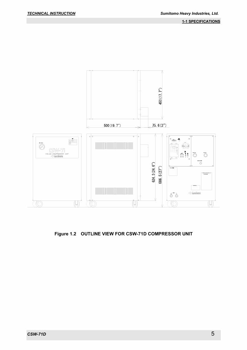
1-2 CONSTRUCTION 1-2-2 GAS AND OIL FLOW IN THE COMPRESSOR UNIT The flow diagram for CSW-71D Compressor Unit is shown in Figure 1.4. Internal components diagram and its functions are described in Figure 1.5 and Table 1.4. The Compressor Unit works as follows; 1) Low pressure He gas discharged from a Cold Head can be led through a HE-GAS RETURN
CONNECTOR to the Compressor Unit. 2) The low pressure (Return) He gas can pass through a STORAGE TANK and a FILTER, and flow
into a COMPRESSOR CAPSULE. 3) The low pressure He gas will be compressed and pressurized in the COMPRESSOR CAPSULE,
and the high pressure with high temperature He gas after the compression will be discharged from the COMPRESSOR CAPSULE outlet.
4) The high pressure with high temperature He gas will be led to a water cooled HE-GAS COOLER
and cooled down in the cooler. 5) The high pressure He gas after cooling will flow into an OIL SEPARATOR to separate an almost all
of lubricating oil mist from the high pressure He gas. 6) The separated lubricating oil can be returned to the COMPRESSOR CAPSULE through a lub oil
return pipings. 7) The high pressure He gas discharged from the OIL SEPARATOR will be led to an ADSORBER. 8) The remained lub oil contents in the high pressure He gas can be adsorbed through an active
charcoal layer to make the high pressure He gas being pure. 9) The pure high pressure He gas can be supplied to the Cold Head through a HE-GAS SUPPLY
CONNECTOR.
TECHNICAL INSTRUCTION Sumitomo Heavy Industries, Ltd.
CSW-71D 10
1-2 CONSTRUCTION
Figure 1.4 HELIUM GAS FLOW DIAGRAM FOR CSW-71D COMPRESSOR UNIT

TECHNICAL INSTRUCTION Sumitomo Heavy Industries, Ltd.
CSW-71D 11
1-2 CONSTRUCTION 1-2-3 INTERNAL COMPONENTS The parts list and its functions are described in Table 1.4. The He-gas flow diagram and internal components are shown in Figure 1.4 and Figure 1.5.
Table 1.4. FUNCTIONS OF THE INTERNAL COMPONENTS FOR CSW-71D COMPRESSOR UNIT
No. PARTS FUNCTIONS 1 OIL CHARGE CONNECTOR To use for refilling a lubricating oil. 2 FILTER To eliminate contaminators and debris from a recirculating lub oil.
4 FILTER To eliminate contaminators and debris from a He-gas suction for a Compressor Capsule.
5 HE-GAS RETURN CONNECTOR To use for connecting a Flex Line (for Return He-gas line). 6 STORAGE TANK A He-gas reservoir for piping to Compressor Capsule. 7 SOLENOID VALVE An electro-magnetic operation valve for He-gas piping. 8 RELIEF VALVE To keep a maximum high pressure for the He-gas piping safely.
9 ADSORBER To use for eliminating a remained oil mist in the compressed He-gas after treatment by the Oil Separator.
10 HE-GAS SUPPLY CONNECTOR To use for connecting a Flex Line (for Supply He-gas line). 11 HE-GAS CHARGE CONNECTOR To use for charging and refilling a He-gas. 12 OIL SEPARATOR To eliminate oil contamination from the compressed He-gas. 13 OIL COOLER A water cooled type heat exchanger for recirculating lub oil. 15 COMPRESSOR CAPSULE A He-gas compressed for the unit.
16 THERMOSTAT : TS1 110 deg.C
A thermal sensor & controller for the compressed He-gas temperature of compressor outlet.
17 HE-GAS COOLER A water cooled type heat exchanger for compressed He-gas.
18 THERMOSTAT : TS2 60 deg.C
A thermal sensor & controller for the compressed He-gas temperature of He-gas cooler outlet.
19 FILTER To eliminate contaminators and debris from a lub oil return of Oil Separator.
20 PRESSURE GAUGE To indicate a filled He-gas pressure and compressed He-gas pressure of the unit.
21 HIGH SIDE PRESSURE SWITCH : PSH A pressure sensor for compressed He-gas pressure control.
22 ORIFICE To use for adjusting a recirculating lub oil flow.
23 LOW SIDE PRESSURE SWITCH : PSL A pressure sensor for compressed He-gas pressure control.
24 THERMOSTAT : TS3 60 deg.C
A thermal sensor & controller for the water temperature of cooling water outlet.
26 COOLING WATER INLET CONNECTOR To use for connecting a cooling water piping (for War Supply)
27 COOLING WATER OUTLET CONNECTOR To use for connecting a cooling water piping (for Water Discharge)
28 CONTROL BOX An electronic control, surveillance and alarming system for the He-gas Compressor Unit.

TECHNICAL INSTRUCTION Sumitomo Heavy Industries, Ltd.
CSW-71D 12
1-2 CONSTRUCTION
Figure 1.5 COMPONENTS OF CSW-71D COMPRESSOR UNIT

TECHNICAL INSTRUCTION Sumitomo Heavy Industries, Ltd.
CSW-71D 13
1-3 ELECTRICAL DESCRIPTION 1-3 ELECTRICAL DESCRIPTION 1-3-1 EXTERNAL CONNECTOR
<Warning about electric shock>
This cryocooler includes a high-voltage section. Touching it may result in electric shock. Handle it with extreme care. Pay special attention to its wiring when using the external connector on the compressor unit. Connecting a jumper wire between Pins No.6 - No.8, No.6 - No.13 and No.6 - No.15 may result in misoperation in some of safety devices in the equipment, causing electric shock, burn or malfunction.
“IMPORTANT”
See “ELECTRICAL SCHEMATIC” of CSW-71D Compressor Unit, for detail. “IMPORTANT”
The maximum allowable tightening torque of the D-Sub Connector lock screw (#4-40UNC) is 0.17 Nm. External Connector can be used monitoring the status of the Compressor Unit and the remote control sequences of the Compressor Unit are described in Table 1.5. The “D-sub” pins indicated in Figure 1.6 on the control panel for the Compressor Unit can be applied to an initial condition monitoring for a first-aid diagnostics of the Compressor Unit by means of measuring the each item with a digital Volt/Ohm Meter. The Fault Condition classified the digital meter reading as referred to the Table 1.5 can be identified simply an actual operation condition of the Compressor Unit in the field.
Table 1.5 EXTERNAL CONTROL / ALARM
No. ITEM OPERATION PIN No. FAULT CONDITION* Normal Close 1 Pressure Alarm
Signal Contact Alarm Open
1, 2 > 106 ohm
Normal Close 2 Temp. Alarm Signal Contact
Alarm Open 3, 4 > 106 ohm
Operate 24V DC(0.15A max.) 3 Drive Indication DC Power Stop 0V
6, 7 0 V
4 Control Voltage DC Power
Output 24V DC(0.15A max.), when Main Power SW is “ON” 7, 13
5 Remote Reset Relay Pulsed 24VDC for 1 second to be furnished by user. 12, 14
Drive Close 6 Remote Drive Contact Stop Open
8, 15
* Digital Volt./Ohm Meter Reading
91015 14 13 12 11
8 1234567
Figure 1.5 EXTERNAL CONNECTOR WIRING ON THE COMPRESSOR UNIT
WARNING

TECHNICAL INSTRUCTION Sumitomo Heavy Industries, Ltd.
CSW-71D 14
1-3 ELECTRICAL DESCRIPTION 1-3-2 SAFETY DEVICES The safety devices list for Compressor Unit is shown in Table 1.6.
Table 1.6 SAFETY DEVICES OF CSW-71D
ITEM FUNCTIONS
THERMOSTAT : (TS1)
Setting temperature; 110 deg.C ---- approx. To shut down the Compressor Unit and signal a high temperature alarm to the External Connector, in case of higher temperature of a compressed He-gas at a compressor outlet than the setting temperature.
THERMOSTAT : (TS2)
Setting temperature; 60 deg.C ---- approx. To shut down the Compressor Unit and signal a high temperature alarm to the External Connector, in case of higher temperature of a compressed He-gas at a He-gas cooler outlet than the setting temperature.
THERMOSTAT : (TS3)
Setting temperature; 60 deg.C ---- approx. To shut down the Compressor Unit and signal a higher temperature alarm to the External Connector, in case of higher temperature of a water at a cooling water outlet than the setting temperature.
SOLENOID VALVE : (YV) To stabilize a pressure for even of the He-gas between the Supply and Return piping, at a shut off the Compressor Unit.
HIGH PRESSURE SWITCH : (PSH)
Setting pressure; “Operate” 2.55 MPa ---- approx. “Reset” 2.26 MPa ---- approx. To adjust a Supply He-gas pressure smoothly by a function of the pressure switch for Open and/or Shut, in case of higher pressure of the Supply He-gas than the setting pressure.
LOW PRESSURE SWITCH : (PSL)
Setting Pressure; “Operate” 0.15 MPa ---- approx. To shut down the Compressor Unit and signal a Low pressure alarm to the External Connector, in case of lower pressure of a compressed He-gas caused by a smaller quantity of He-gas than original filling in the compressor unit.
RELIEF VALVE
Setting pressure; “Operate” 2.61 - 2.75 MPa “Reset” 2.50 MPa ---- minimum To adjust a Supply He-gas pressure smoothly by a function of the Relief Valve for blowing off the He-gas to the atmosphere, in case of higher pressure of Supply He-gas than the setting pressure.
MAIN POWER SWITCH : (QF1)
Setting current; 13 A To shut down the Compressor Unit, in case of occurring over-current and/or short-circuit than the setting current.
PHASE FAILURE PROTECTION CIRCUIT :
To avoid starting-up of the Compressor Unit in case of an abnormal operation caused by irregular connecting of Input Power Cable such as failure connecting.
FUSE : (FU1, FU2, FU3, FU4)
To protect the Compressor Unit from the over-load caused by short-circuit and/or any other electrical failure in the DC power or the Solenoid Valve.

TECHNICAL INSTRUCTION Sumitomo Heavy Industries, Ltd.
CSW-71D 15
2 INSTALLATION 2 INSTALLATION
<Warning about electric shock>
This cryocooler includes a high-voltage section. Touching it may result in electric shock. Handle it with extreme care. Make sure no power is applied to the compressor unit before starting the installation. Failing to observe this precaution may result in electric shock. Do not install the equipment near places subject to condensation such as a watering place. Failing to observe this precaution may result in electric shock or malfunction. Do not install the equipment in a dusty environment. Failing to observe this precaution may result in electric shock or malfunction. Make sure the power specification of the cryocooler used conforms to the customer's power supply before using the equipment. Using the cryocooler with a non-conforming power supply may result in electric shock or malfunction. If the compressor unit used is the CSW-71D (water cooled, high voltage type), pay attention to the setting of the applicable input supply voltage. The product is shipped with the input supply voltage set to 480V. Before installing the equipment, be sure to check your supply voltage and change it to the appropriate setting if necessary. Operating the equipment with your supply voltage different from the setting of the compressor unit may result in electric shock or malfunction. Make sure no power is applied to the compressor unit before starting operation when connecting or disconnecting the cold head power cable. Failing to observe this precaution may result in electric shock. Be sure to turn off and Lock Out with OFF position the main power of the customer's power source before connecting or disconnecting the input power cable to the Compressor Unit, and then remove the input power cable from the main power. Failing to observe this precaution may result in electric shock. Do not change the setting of the dial above the main power switch of the compressor unit under any circumstances. Failing to observe this precaution may result in electric shock.
<Warning about explosion, escape of gas>
This cryocooler (cold head, compressor unit, compressor adsorber, flex lines) contains a high-pressure (about 1.62 MPa helium gas sealed in. Hitting the equipment with a sharp edge or touching it with a pointed object may cause explosion or escape of gas. Handle the equipment with extreme care. The minimum bending radius of the flex lines is 150mm (intermediate), 300 mm (terminal). Bending the flex lines at a smaller angle may cause explosion or escape of gas, and so this should be avoided. Do not disassemble the equipment for purposes other than maintenance specified in this service manual under any circumstances. Disassembling the equipment may result in electric shock, explosion or escape of gas. Install the cryocooler in the ventilated area, otherwise it may result in asphyxiation in case the helium gas is purged or leaked.
Do not put the heat sensitive or flammable object neat the Compressor Unit, or result in fire, injury or malfunction of the system.
WARNING
WARNING
WARNING
TECHNICAL INSTRUCTION Sumitomo Heavy Industries, Ltd.
CSW-71D 16
2 INSTALLATION <Caution against misoperation>
Do not tilt it by more than 30 degrees when carrying the compressor unit. Tilting it by more than 30 degrees may cause oil sealed in the unit to move, preventing the cryocooler from operating normally. This cryocooler is intended for the exclusive use indoors. It cannot be used outdoors. Failing to observe this precaution may prevent the cryocooler from operating normally. Do not use inverter for the main power source of the compressor unit. Operating with inverter may result in the damage or malfunction of the compressor electric circuit. Avoid using the transformer for the main power source of the compressor unit. If the transformer is installed at the upstream of the unit, lacking phase protection circuit with the cryocooler occurs in a malfunction. That may result in misoperation or malfunction. When using the transformer, install the other lacking phase protection device in upstream of the transformer. Do not get on the compressor unit or put an object on top of it. Failing to observe this precaution may prevent the cryocooler from operating normally or cause injury. Secure enough space around the compressor unit for heat radiation and maintenance. Failing to secure enough space may result in misoperation or malfunction. (See the technical instruction of the compressor unit used, for details.) If the compressor unit used is a water-cooled type (CSW-71C, CSW-71D), use cooling water with appropriate temperature, flow rate and water quality. Using inappropriate cooling water may result in misoperation or malfunction. (See the technical instruction of the compressor unit used, for details.) If the compressor unit used is a water-cooled type (CSW-71C, CSW-71D), do not use the demineralized water for cooling water. Using demineralized water for cooling water may result in water leakage or malfunction. (See the technical instruction of the compressor unit used, for details.) Be sure to check the flat rubber gasket of the self seal coupling of the cold head and compressor unit for dirt, dust or to see whether the flat rubber gasket is attached correctly, before connecting the flex lines. Connecting the flex lines with an abnormal flat rubber gasket setting may cause escape of gas. This cryocooler (cold head, compressor unit, compressor adsorber, flex lines) is shipped with a helium gas at about 1.62 MPa sealed in. Be sure to adjust the pressure to an appropriate value according to the cold head used before operating the equipment. Using the cryocooler at an improper pressure may cause misoperation. Pay attention to the contamination when charging a helium gas. The contamination may result in occurrence of the noise from the Cold Head or decreasing the cooling capacity.
CAUTION
TECHNICAL INSTRUCTION Sumitomo Heavy Industries, Ltd.
CSW-71D 17
2-1 SITE REQUIREMENT 2-1 SITE REQUIREMENT
<Caution against misoperation> Do not use inverter for the main power source of the compressor unit. Operating with inverter may result in the damage or malfunction of the compressor electric circuit. Avoid using the transformer for the main power source of the compressor unit. If the transformer is installed at the upstream of the unit, lacking phase protection circuit with the cryocooler occurs in a malfunction. That may result in misoperation or malfunction. When using the transformer, install the other lacking phase protection device in upstream of the transformer. Secure enough space around the compressor unit for heat radiation and maintenance. Failing to secure enough space may result in misoperation or malfunction. (See the technical instruction of the compressor unit used, for details.) If the compressor unit used is a water-cooled type (CSW-71C, CSW-71D), use cooling water with appropriate temperature, flow rate and water quality. Using inappropriate cooling water may result in misoperation or malfunction. (See the technical instruction of the compressor unit used, for details.) If the compressor unit used is a water-cooled type (CSW-71C, CSW-71D), do not use the demineralized water for cooling water. Using demineralized water for cooling water may result in water leakage or malfunction. (See the technical instruction of the compressor unit used, for details.)
・ An almost level and even area in the field will be selected to install the Compressor Unit. ・ An area to be influenced by splashing water and/or dusts will not be selected to install the
Compressor Unit installation area. ・ A clean environmental condition without dirt and/or free from an exhausted heat will be selected to
install the Compressor Unit in the field. ・ A quality of cooling water will be secured to use for an appropriate coolant for the Compressor Unit. ・ Any heat sensitive object cannot be positioned on surroundings of the Compressor Unit. AMBIENT TEMPERATURE CONDITION
The ambient temperature must be between 5 deg.C and 28 deg.C to get the specified capacity. The system can operate up to 35 deg.C with less than 5% cooling capacity down. The maximum relative air humidity is 85%RH.
HELIUM SUPPLY SYSTEM A helium supply system is necessary if you need to decontaminate the helium gas, or charging the helium gas that has leaked out of the system. A helium supply system includes a Grade 5 (99.999% up pure) helium gas bottle, a regulator, an outlet valve, and a charging hose or equivalent delivery line.
POWER SOURCE
Ensure the correct AC power source is available for the compressor. See Table 1.1 for the power requirements for your system.
COOLING WATER
Ensure the correct cooling water is available for the compressor. See Figure 1.1 and Table 1.2. for the cooling water requirements for your system. Operating with Antifreeze (50/50 % mixture of water and ethylene glycol), the flow rate shall be larger than the water. See Figure 1.1 and Table 1.2. for the cooling water requirements for your system.
SAFETY / SEISMIC REQUIREMENT
Secure to lock the locking device of compressor castor. SERVICE AREA
The Compressor Unit should have enough space as shown in Figure 2.1.
CAUTION

TECHNICAL INSTRUCTION Sumitomo Heavy Industries, Ltd.
CSW-71D 18
2-1 SITE REQUIREMENT
Figure 2.1 WATER-COOLED COMPRESSOR UNIT CSW-71D AND ITS REQUIRED SPACE

TECHNICAL INSTRUCTION Sumitomo Heavy Industries, Ltd.
CSW-71D 19
2-2 INPUT POWER CABLE CONNECTION 2-2 INPUT POWER CABLE CONNECTION
<Warning about electric shock>
Make sure the power specification of the cryocooler used conforms to the customer's power supply before using the equipment. Using the cryocooler with a non-conforming power supply may result in electric shock or malfunction. Be sure to turn off and Lock Out with OFF position the main power of the customer's power source before connecting or disconnecting the input power cable to the Compressor Unit, and then remove the input power cable from the main power. Failing to observe this precaution may result in electric shock. Do not change the setting of the dial above the main power switch of the compressor unit under any circumstances. Failing to observe this precaution may result in electric shock.
<Caution against misoperation>
Do not use inverter for the main power source of the compressor unit. Operating with inverter may result in the damage or malfunction of the compressor electric circuit. Avoid using the transformer for the main power source of the compressor unit. If the transformer is installed at the upstream of the unit, lacking phase protection circuit with the cryocooler occurs in a malfunction. That may result in misoperation or malfunction. When using the transformer, install the other lacking phase protection device in upstream of the transformer.
“IMPORTANT”
This cryocooler is provided with a phase reverse protection circuit for the input power. If the input power is connected with reverse phase, the cryocooler does not start.
“IMPORTANT”
See “ELECTRICAL SCHEMATIC” of CSW-71D Compressor Unit, for detail.
“IMPORTANT” See “INPUT POWER CABLE HV” of “APPENDIX” for detail.
Make electrical connection as follows;
Upstream Protection Use the fuses or circuit breakers as upstream protection of L1, L2, L3. The recommended rating of the protection is maximum 30A.
Power Supply Conductor and Protective Earth Conductor
Use 75 deg.C wiring sized to 60 deg.C ampacity. Use copper conductor only. AWG 12 (3.3 mm2) or larger.
Compressor Unit Side Power Supply Conductors Protective Earth Conductor Striping Length: 12 mm Striping Length: 12 mm Tightening Torque: 1.3 Nm Tightening Torque: 1.8 Nm
User’s Power Source Side Power Supply Conductors Protective Earth Conductor Striping Length: 12 mm Striping Length: 12 mm
WARNING
CAUTION

TECHNICAL INSTRUCTION Sumitomo Heavy Industries, Ltd.
CSW-71D 20
2-2 INPUT POWER CABLE CONNECTION See the Table 1.1 for power requirements. The cables are marked with label and connect as follows:
L1 L2 L3
L1
L2
L3
Ground
For User'sPower Source
FIELDTEMINAL
GROUNDINGTEMINAL
ForCompressor Unit
WIRING DIAGRAM
Input Power Voltage Setting The Compressor Unit can be operated on various input power voltages by changing the terminal wiring in the Compressor Unit. This terminal is located inside of the Control Box. See the Figure 2.2 for voltage setting. Initial factory setting is AC480V / 60Hz.
Position of Wire Connection 480V at 60Hz 460V at 60Hz 415V at 50Hz 400V at 50Hz 380V at 50Hz
480
460
415
400
380
480
460
415
400
380
480
460
415
400
380
1L3
1L2
1L1
480
460
415
400
380
480
460
415
400
380
480
460
415
400
380
1L3
1L2
1L1
480
460
415
400
380
480
460
415
400
380
480
460
415
400
380
1L3
1L2
1L1
480
460
415
400
380
480
460
415
400
380
480
460
415
400
380
1L3
1L2
1L1
480
460
415
400
380
480
460
415
400
380
480
460
415
400
380
1L1
1L2
1L3
Figure 2.2 TERMINAL WIRING FOR INPUT POWER VOLTAGE
Control Box
Terminal Block

TECHNICAL INSTRUCTION Sumitomo Heavy Industries, Ltd.
CSW-71D 21
3 MAINTENANCE 3 MAINTENANCE
<Warning about electric shock>
This cryocooler includes a high-voltage section. Touching it may result in electric shock. Handle it with extreme care. Make sure no power is applied to the compressor unit before starting the installation. Failing to observe this precaution may result in electric shock. Be sure to turn off and Lock Out with OFF position the main power of the customer's power source before connecting or disconnecting the input power cable to the Compressor Unit, and then remove the input power cable from the main power. Failing to observe this precaution may result in electric shock. Do not change the setting of the dial above the main power switch of the compressor unit under any circumstances. Failing to observe this precaution may result in electric shock. Be sure to turn off and Lock Out with OFF position the customer's main power before performing maintenance work such as replacement of fuses. Failing to observe this precaution may result in electric shock.
<Warning about explosion, escape of gas>
This cryocooler (cold head, compressor unit, compressor adsorber, flex lines) contains a high-pressure (about 1.62 MPa helium gas sealed in. Hitting the equipment with a sharp edge or touching it with a pointed object may cause explosion or escape of gas. Handle the equipment with extreme care. Do not disassemble the equipment for purposes other than maintenance specified in this service manual under any circumstances. Disassembling the equipment may result in electric shock, explosion or escape of gas. The cold head, compressor unit, compressor adsorber and flex lines are pressurized with helium gas. Purge the helium gas from all pressurized components before disposing. Open the purging valve gradually or it may result in serious injury. When scrapping the CryoCooler, handle it as Industrial Waste and pass it over to legally qualified disposer. Install the cryocooler in the ventilated area, otherwise it may result in asphyxiation in case the helium gas is purged or leaked.
The Adsorber weight is about 11.0kg. When replace the adsorber, be careful of handling so that it may not get hurt. <Caution against misoperation>
Do not get on the compressor unit or put an object on top of it. Failing to observe this precaution may prevent the cryocooler from operating normally or cause injury. Secure enough space around the compressor unit for heat radiation and maintenance. Failing to secure enough space may result in misoperation or malfunction. (See the technical instruction of the compressor unit used, for details.) If the compressor unit used is a water-cooled type (CSW-71C, CSW-71D), use cooling water with appropriate temperature, flow rate and water quality. Using inappropriate cooling water may result in misoperation or malfunction. (See the technical instruction of the compressor unit used, for details.) The cold head drive switch provided with the compressor unit is only used for maintenance. Be sure to turn it OFF in normal operation. Using the compressor unit with the cold head drive switch turned ON may result in misoperation or malfunction.
WARNING
WARNING
CAUTION
WARNING

TECHNICAL INSTRUCTION Sumitomo Heavy Industries, Ltd.
CSW-71D 22
3-1 PERIODICAL MAINTENANCE 3-1 PERIODICAL MAINTENANCE CSW-71D Compressor Unit is to be required the routine maintenance. The basic maintenance work is to replace the oil mist Adsorber of the Compressor Unit for every 20,000 Hrs operation as mentioned Table 3.1.
Table 3.1 MAINTENANCE SCHEDULE
MAINTENANCE FREQUENCY REMARKS Replace Compressor Adsorber Every 20,000 Hrs. Charge Helium Gas to Compressor As required
Cleaning Water Cooler As required Depending on the water conditions.
Compressor Fuse Replacement As required
Table 3.2 RENEWAL PARTS LIST (FRU’S)
ITEM DESCRIPTION Q’TY PART NUMBER REMARKS 1 Adsorber 1 RE71TN0408
2 Fuse
(FU1, FU2, FU3) 3 RE71WT0768 Class G Fuse 1A
3 Fuse (FU4)
1 RE71WT0767 Glass Body Fuse 1A
4 Hose Nipple 2 RE38VT0689 OD:12.7mm x PT3/8 (male)

TECHNICAL INSTRUCTION Sumitomo Heavy Industries, Ltd.
CSW-71D 23
3-1 PERIODICAL MAINTENANCE 3-1-1 REPLACEMENT OF THE COMPRESSOR ADSORBER
<Warning about explosion, escape of gas>
This cryocooler (cold head, compressor unit, compressor adsorber, flex lines) contains a high-pressure (about 1.62 MPa helium gas sealed in. Hitting the equipment with a sharp edge or touching it with a pointed object may cause explosion or escape of gas. Handle the equipment with extreme care. Do not disassemble the equipment for purposes other than maintenance specified in this service manual under any circumstances. Disassembling the equipment may result in electric shock, explosion or escape of gas. The cold head, compressor unit, compressor adsorber and flex lines are pressurized with helium gas. Purge the helium gas from all pressurized components before disposing. Open the purging valve gradually or it may result in serious injury. When scrapping the CryoCooler, handle it as Industrial Waste and pass it over to legally qualified disposer. Install the cryocooler in the ventilated area, otherwise it may result in asphyxiation in case the helium gas is purged or leaked.
The Adsorber weight is about 11.0kg. When replace the adsorber, be careful of handling so that it may not get hurt. <Caution against misoperation>
Do not get on the compressor unit or put an object on top of it. Failing to observe this precaution may prevent the cryocooler from operating normally or cause injury.
The Oil Mist Adsorber is required to replace for every 20,000 Hrs operation.
Table 3.3 ADSORBER FOR COMPRESSOR UNIT
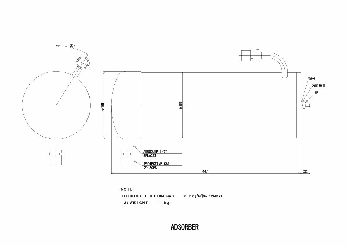
DESCRIPTION Q’TY PART NUMBER REMARKS 1 Adsorber 1 RE71TN0408
Table 3.4 REQUIRED TOOLS FOR ADSORBER REPLACEMENT
TOOLS REMARKS 1 1“ open-end wrench For Aero-quip coupling 2 1-1/8“ Open-end wrench For Aero-quip coupling 3 1-3/16“ Open-end wrench For Aero-quip coupling 4 Snoop liquid For leak check 5 Cotton wipers For leak check 6 13 mm Open-end wrench For fixing nut for Adsorber 7 Screw driver (phillips(+)) For side panel of Compressor Unit.
WARNING
CAUTION
WARNING

TECHNICAL INSTRUCTION Sumitomo Heavy Industries, Ltd.
CSW-71D 24
3-1 PERIODICAL MAINTENANCE Replace the Adsorber instructed as follows; PREPARATION 1) Shut down the Cryocooler. 2) Disconnect the Input Power Cable from the Compressor Unit. 3) Disconnect the Supply and Return Flex Lines from the Compressor Unit. REMOVING THE USED ADSORBER 1) Loosen the screws that hold the compressor side panel and remove the panel.
2) Disconnect the Adsorber Self-Sealing Coupling. Use three wrenches.
3) Remove the Nut secured the Adsorber to Rear Panel. Use two wrenches.
TECHNICAL INSTRUCTION Sumitomo Heavy Industries, Ltd.
CSW-71D 25
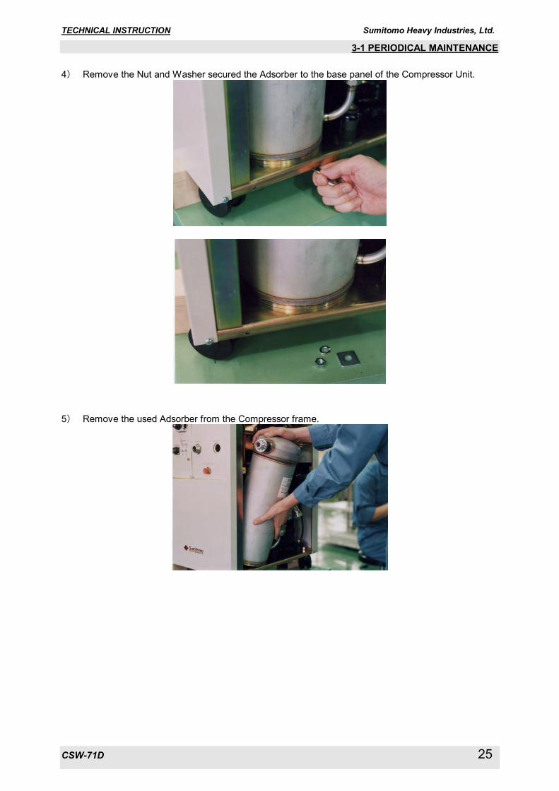
3-1 PERIODICAL MAINTENANCE 4) Remove the Nut and Washer secured the Adsorber to the base panel of the Compressor Unit.
5) Remove the used Adsorber from the Compressor frame.

TECHNICAL INSTRUCTION Sumitomo Heavy Industries, Ltd.
CSW-71D 26
3-1 PERIODICAL MAINTENANCE INSTALLING NEW ADSORBER 1) Set a new Adsorber. 2) Secure the Adsorber to the base panel of the Compressor Unit by tightened Nut and Washer.
Tightening Torque: 14.5 Nm 3) Secure the Adsorber to Rear Panel by tightening Nut.
Tightening Torque: 23 Nm 4) Connect the Adsorber Self-Sealing Coupling.
Tightening Torque: 50 Nm 5) Sprinkle “Liquid Leak Detector” on the Flex line connecting coupling, in case the bubbling is found,
tighten the connecting coupling again and re-check the leakage.
Ensure that the pressure gauge indication is specified value for the type of Cold Head. Charge the helium gas, in case of low pressure indicating.
6) Reinstall the panels and secure them by tightening the screws.

TECHNICAL INSTRUCTION Sumitomo Heavy Industries, Ltd.
CSW-71D 27
3-2 FUSE REPLACEMENT 3-2 FUSE REPLACEMENT
<Warning about electric shock>
This cryocooler includes a high-voltage section. Touching it may result in electric shock. Handle it with extreme care. Do not change the setting of the dial above the main power switch of the compressor unit under any circumstances. Failing to observe this precaution may result in electric shock. Be sure to turn off and Lock Out with OFF position the customer's main power before performing maintenance work such as replacement of fuses. Failing to observe this precaution may result in electric shock.
Fuses are equipped inside of the Fuse Box for the Control Box.
Table 3.5 LIST OF FUSES
Fuse No. Description Part Number Remarks FU1, 2, 3 Class G Fuse 1A RE71WT0768
FU4 Glass Body Fuse 1A RE71WT0767
For Cold Head Motor, Solenoid Valve and DC Circuit.
FUSE REPLACING PROCEDURE 1) Loosen the screws that hold the compressor side panel, and remove the panel. 2) Replace the Fuses.
FU3 FU2
FU1
FU4
WARNING

TECHNICAL INSTRUCTION Sumitomo Heavy Industries, Ltd.
CSW-71D 28
APPENDIX APPENDIX ELECTRICAL SCHEMATIC
No. PART NAME 1 ELECTRICAL SCHEMATIC of CSW-71D (FOR AC CIRCUIT) 2 ELECTRICAL SCHEMATIC of CSW-71D (FOR DC CIRCUIT)
DRAWINGS
No. PART NAME 1 ADSORBER 2 CLASS G FUSE 1A 3 GLASS BODY FUSE 1A 4 INPUT POWER CABLE HV


TECHNICAL INSTRUCTION Sumitomo Heavy Industries, Ltd.
CSW-71D
REVISION CONTROL REVISION CONTROL
Manual No. Revision Remarks Date
-A Publication of first edition. DEC. 10 / 1999 -B Change the Electrical Schematic Diagram. APR. 4 / 2000 -C Delete the description of “water temp. alarm signal“. JAN. 11 / 2001 -D Change the SHI address. JAN. 25 / 2001 -E Delete the description of spare fuse. JAN. 30 / 2001 -F Change the Electrical Schematic Diagram. FEB. 19 / 2001 -G Change the specification of power requirement. MAR. 21 / 2001
-H Add the specification of recommended power requirement and description of demineralized water.
APR. 1 / 2002
-I Change the dimension. MAY 31 / 2002
-J Correct the descriptions of Input Power Cable Connection.
JUL 11 / 2002
-K Add the transformer-use CAUTION FEB. 28 / 2003 -L Change the division name. JUNE 9 / 2003
-M Add the description for the RDK-408D2 and S2 Cold Head.
DEC. 18 / 2003
-N
The information of the SHI inquiries and typographical error was corrected. The descriptionof the Cooling Water requirement was revised.
JAN. 12 / 2006
-P Electrical Schematic (2/2) was corrected. Add the specification for the D-Sub Connector lock screw tighten torque.
AUG 21 / 2008
-Q The Humidity Range was added. DEC. 1 / 2009
CD32ZZ-069