Embed Size (px)
Citation preview
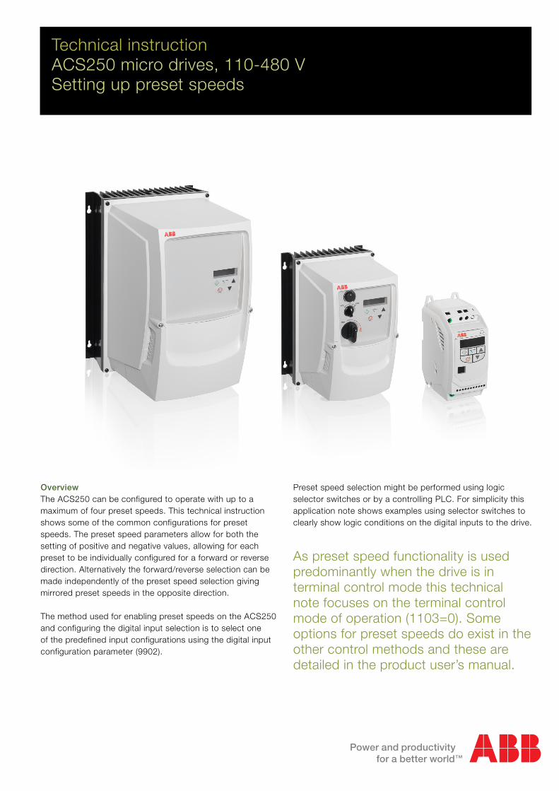
Technical instructionACS250 micro drives, 110-480 VSetting up preset speeds
OverviewThe ACS250 can be configured to operate with up to a maximum of four preset speeds. This technical instruction shows some of the common configurations for preset speeds. The preset speed parameters allow for both the setting of positive and negative values, allowing for each preset to be individually configured for a forward or reverse direction. Alternatively the forward/reverse selection can be made independently of the preset speed selection giving mirrored preset speeds in the opposite direction.
The method used for enabling preset speeds on the ACS250 and configuring the digital input selection is to select one of the predefined input configurations using the digital input configuration parameter (9902).
Preset speed selection might be performed using logic selector switches or by a controlling PLC. For simplicity this application note shows examples using selector switches to clearly show logic conditions on the digital inputs to the drive.
As preset speed functionality is used predominantly when the drive is in terminal control mode this technical note focuses on the terminal control mode of operation (1103=0). Some options for preset speeds do exist in the other control methods and these are detailed in the product user’s manual.
2 Technical instruction | Setting up preset speeds (110-480 V)
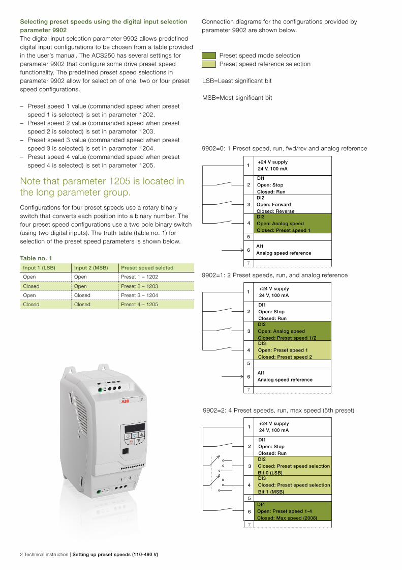
9902=2: 4 Preset speeds, run, max speed (5th preset)
9902=1: 2 Preset speeds, run, and analog reference
9902=0: 1 Preset speed, run, fwd/rev and analog reference
Connection diagrams for the configurations provided by parameter 9902 are shown below.
Preset speed mode selectionPreset speed reference selection
LSB=Least significant bit
MSB=Most significant bit
DI3Open: Analog speedClosed: Preset speed 1
+24 V supply24 V, 100 mA
DI1Open: StopClosed: Run
AI1Analog speed reference
DI2Open: ForwardClosed: Reverse
1
2
3
4
6
5
7
1
2
3
4
6
5
7
DI3Open: Preset speed 1Closed: Preset speed 2
+24 V supply24 V, 100 mA
DI1Open: StopClosed: Run
AI1Analog speed reference
DI2Open: Analog speedClosed: Preset speed 1/2
1
2
3
4
6
5
7
DI3Closed: Preset speed selectionBit 1 (MSB)
+24 V supply24 V, 100 mA
DI1Open: StopClosed: Run
DI4Open: Preset speed 1-4 Closed: Max speed (2008)
DI2Closed: Preset speed selectionBit 0 (LSB)
Selecting preset speeds using the digital input selection parameter 9902The digital input selection parameter 9902 allows predefined digital input configurations to be chosen from a table provided in the user’s manual. The ACS250 has several settings for parameter 9902 that configure some drive preset speed functionality. The predefined preset speed selections in parameter 9902 allow for selection of one, two or four preset speed configurations.
– Preset speed 1 value (commanded speed when preset speed 1 is selected) is set in parameter 1202.
– Preset speed 2 value (commanded speed when preset speed 2 is selected) is set in parameter 1203.
– Preset speed 3 value (commanded speed when preset speed 3 is selected) is set in parameter 1204.
– Preset speed 4 value (commanded speed when preset speed 4 is selected) is set in parameter 1205.
Note that parameter 1205 is located in the long parameter group.
Configurations for four preset speeds use a rotary binary switch that converts each position into a binary number. The four preset speed configurations use a two pole binary switch (using two digital inputs). The truth table (table no. 1) for selection of the preset speed parameters is shown below.
Table no. 1
Input 1 (LSB) Input 2 (MSB) Preset speed selcted
Open Open Preset 1 – 1202
Closed Open Preset 2 – 1203
Open Closed Preset 3 – 1204
Closed Closed Preset 4 – 1205
Setting up preset speeds (110-480 V) | Technical instruction 3
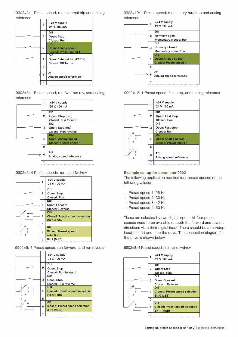
9902=3: 1 Preset speed, run, external trip and analog reference
9902=5: 1 Preset speed, run fwd, run rev, and analog reference
9902=8: 4 Preset speeds, run, and fwd/rev
9902=9: 4 Preset speed, run forward, and run reverse
DI3Open: Analog speedClosed: Preset speed 1
+24 V supply24 V, 100 mA
DI1Open: Stop (fwd)Closed: Run forward
AI1Analog speed reference
DI2Open: Stop (rev)Closed: Run reverse
1
2
3
4
6
5
7
DI3Open: External trip (F0014)Closed: OK to run
+24 V supply24 V, 100 mA
DI1Open: StopClosed: Run
AI1Analog speed reference
DI2Open: Analog speedClosed: Preset speed 1
1
2
3
4
6
5
7
1
2
3
4
6
5
7
DI3Closed: Preset speed selectionBit 0 (LSB)
+24 V supply24 V, 100 mA
DI1Open: StopClosed: Run
DI4Closed: Preset speed selectionBit 1 (MSB)
DI2Open: ForwardClosed: Reverse
1
2
3
4
6
5
7
DI3Closed: Preset speed selectionBit 0 (LSB)
+24 V supply24 V, 100 mA
DI1Open: StopClosed: Run forward
DI4Closed: Preset speed selectionBit 1 (MSB)
DI2Open: StopClosed: Run reverse
9902=10: 1 Preset speed, momentary run/stop and analog reference
Example set up for parameter 9902The following application requires four preset speeds of the following values:
– Preset speed 1, 25 Hz – Preset speed 2, 33 Hz – Preset speed 3, 42 Hz – Preset speed 4, 50 Hz
These are selected by two digital inputs. All four preset speeds need to be available on both the forward and reverse directions via a third digital input. There should be a run/stop input to start and stop the drive. The connection diagram for the drive is shown below.
9902=8: 4 Preset speeds, run, and fwd/rev
9902=12: 1 Preset speed, fast stop, and analog reference
1
2
3
4
6
5
7
DI3Open: Analog speedClosed: Preset speed 1
+24 V supply24 V, 100 mA
DI1Normally openMomenatry closed: Run
AI1Analog speed reference
DI2Normally closedMomentary open: Run
1
2
3
4
6
5
7
DI3Open: Analog speedClosed: Preset speed 1
+24 V supply24 V, 100 mA
DI1Open: Fast stopClosed: Run
AI1Analog speed reference
DI2Open: Fast stopClosed: Run
1
2
3
4
6
5
7
DI3Closed: Preset speed selectionBit 0 (LSB)
+24 V supply24 V, 100 mA
DI1Open: StopClosed: Run
DI4Closed: Preset speed selectionBit 1 (MSB)
DI2Open: ForwardClosed : Reverse
3AU
A00
0015
6983
RE
V A
EN
6.5
.201
5
For more information please contact your local ABB representative or visit:
www.abb.com/drives
© Copyright 2014 ABB. All rights reserved. Specifications subject to change without notice.
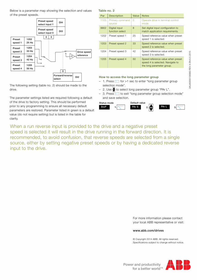
When a run reverse input is provided to the drive and a negative preset speed is selected it will result in the drive running in the forward direction. It is recommended, to avoid confusion, that reverse speeds are selected from a single source, either by setting negative preset speeds or by having a dedicated reverse input to the drive.
Par Description Value Notes
1103 Primary command source
0 Operate drive in terminal control mode.
9902 Digital input function select
8 Set digital input configuration to match application requirements.
1202 Preset speed 1 25 Speed reference value when preset speed 1 is selected.
1203 Preset speed 2 33 Speed reference value when preset speed 2 is selected.
1204 Preset speed 3 42 Speed reference value when preset speed 3 is selected.
1205 Preset speed 4 50 Speed reference value when preset speed 4 is selected. Navigate to the long parameter group.
The following setting (table no. 2) should be made to the drive.
The parameter settings listed are required following a default of the drive to factory setting. This should be performed prior to any programming to ensure all necessary default parameters are restored. Parameter listed in green is a default value (do not require setting) but is listed in the table for clarity.
Presetspeed 1
Preset speedselect input 1
120225 Hz
Preset speedselect input 0
Presetspeed 4
Presetspeed 3
Presetspeed 2
120333 Hz
120442 Hz
120550 Hz
DI4
DI3
-1
Drive speed reference
0 0
0
DI2Forward/reverse select
Below is a parameter map showing the selection and values of the preset speeds.
Table no. 2
How to access the long parameter group – 1. Press for >1 sec to enter “long parameter group
selection mode”. – 2. Use to select long parameter group “PAr L”. – 3. Press to exit “long parameter group selection mode”
and save selection.
StoP PAr L
Status mode
PAr S
Default value
2. 3.1.