Embed Size (px)
Citation preview
TechnicalInformation
Installation Guidancefor N-IO field enclosure
TI 30A30A10-01EN
TI 30A30A10-01EN©Copyright Feb. 2018 (YK)6th Edition May 2021 (YK)
Yokogawa Electric Corporation2-9-32, Nakacho, Musashino-shi, Tokyo, 180-8750 Japan
i
TI 30A30A10-01EN
IntroductionThe N-IO field enclosure is a standardized remote I/O enclosure for outdoor use, which include N-IO node. There are two types of N-IO field enclosure, one is for CENTUM VP and the other is for ProSafe-RS.This document provides guidance that allows users to consider how to accumulate the power capacity and install devices at a planning stage of deploying the N-IO field enclosures for CENTUM VP and ProSafe-RS.The contents of this manual are based on the style of hardware and the specifications of software release at the time of publication of this manual.
Chapter 1 System installation requirementsThis chapter describes specifications covering N-IO field enclosure installation and environmental specifications, inrush current, power consumption, noise prevention, and grounding necessary for designing a power supply system.
Chapter 2 Transportation, storage and installationThis chapter describes general cautions for transporting and carrying the N-IO field enclosure which is a precision device, precautions for temperature and humidity changes when unpacking or storing it temporarily, space necessary for maintenance (servicing area), and how to install devices.
Chapter 3 CablingThis chapter describes how to connect power, grounding, signal and communication cables to the installed devices, and how to connect optical fiber cables.
Chapter 4 Installation specificationsThis chapter covers power consumption and power dissipation, in-rush current, circuit protector and breaker ratings, and parts that need replacement within 10 years. Read this section when deciding power supply capacity.
Chapter 5 Post-installation inspection and environmental preservationThis chapter describes items that must be checked before applying power and the precautions to be taken to safeguard the environment after installing the system.
All Rights Reserved Copyright © 2018, Yokogawa Electric Corporation Jan. 14, 2021-00
ii
TI 30A30A10-01EN
Safety Precautions
n Safety, Protection, and Modification of the Product• In order to protect the system controlled by the product and the product itself and ensure
safe operation, observe the safety precautions described in this Technical Information. We assume no liability for safety if users fail to observe these instructions when operating the product.
• If this product is used in a manner not specified in this Technical Information, the protection provided by this product may be impaired.
• If any protection or safety circuit is required for the system controlled by the product or for the product itself, prepare it separately.
• Be sure to use the spare parts approved by Yokogawa Electric Corporation (hereafter simply referred to as YOKOGAWA) when replacing parts or consumables.
• Do not use the accessories (Power supply cord set, etc.) that came with the product for any other products.
• Modification of the product is strictly prohibited.
• The following symbols are used in the product and instruction manual to indicate that there are precautions for safety:
Indicates that caution is required when handling the equipment. This symbol is labeled on the Product to indicate the possibility of dangers such as electric shock on personnel and equipment, and also indicate that the user must refer to this document and the User’s Manuals for necessary actions. In this document and the User’s Manuals, this symbol is used together with a signal word “WARNING” or “CAUTION” at the locations where precautions for avoiding dangers aredescribed.Indicates that caution is required for hot surface. Note that the devices with this symbol become hot. The risk of burn injury or some damages exists if the devices are touched or contacted.Identifies a protective conductor terminal. Ensure to ground the protective conductor terminal to avoid electric shock before using the product.Identifies a functional grounding terminal. A term “FG” is also used. This terminal is equipped with the same function and used for purposes other than the protective grounding. Before using the product, ground the terminal.
Indicates an AC supply.
Indicates a DC supply.
Indicates that the main switch is ON
Indicates that the main switch is OFF
Jan. 14, 2021-00
iii
TI 30A30A10-01EN
n Symbol Marks of Installation GuidanceThroughout this Technical Information, you will find several different types of symbols are used to identify different sections of text. This section describes these icons.
WARNING Identifies important information required to understand operations or functions.
CAUTION Identifies instructions that must be observed in order to avoid physical injury and electric
shock or death to the operator.
IMPORTANTIdentifies important information required to understand operations or functions.
TIP Identifies additional information.
SEE ALSO
Identifies a source to be referred to.
Feb. 26, 2018-00
iv
TI 30A30A10-01EN
n Cautions for Safely Applying the Device
l Wiring Power Cable
WARNINGConnect the power cables according to the procedure in this document. Power cables must conform to the safety standards of the country where the device is installed.
SEE ALSO For wiring power cable, refer to 3.2, “Connecting power cable.”
l Earth Wiring
WARNINGThis equipment requires a protective grounding defined by the safety standard. Ground the device following the procedure in this document to prevent from electric shock and to minimize the noise.
SEE ALSO For earth wiring, refer to 3.3, “Connecting grounding cable.”
l Tightening Torque of Screws
IMPORTANTThe tightening torque that the product recommends is showed in the following table. However, if the tightening torque of the screw is specified in the User’s Manuals, follow the instructions described in the User’s Manuals.
Table Recommended tightening torque
Nominal diameter of a screw M2.6 M3 M3.5 M4 M5 M6 M8 M10Recommended tightening torque (N•m) 0.35 0.6 0.8 1.2 2.8 3.0 12.0 24.0
Feb. 26, 2018-00
v
TI 30A30A10-01EN
l Wiring I/O Cables
CAUTIONWiring I/O cables must follow the procedure in this document.
SEE ALSO For wiring I/O cables, refer to 3.4, “Connecting signal cable.”
l Connecting Devices
IMPORTANTTo ensure this system compliance with the CSA safety standards, all devices connected to this system shall be CSA certified devices.
l Exchanging Fuse
WARNING• The fuses for exchange must be the Yokogawa designated fuses.
l Maintenance
CAUTION• The maintenance work for the devices described in this manual should be performed only
by the educated experts.
• When the device becomes dusty, use a vacuum cleaner or a soft cloth to clean it.
• During maintenance, put up wrist strap, and take other ESD (Electrostatic Discharge) measures.
• If the existing caution label is dirty and illegible, prepare a new label (part number:T9029BX) to replace it.
SEE ALSO For maintenance, refer to 1.4.2, “Countermeasures against static electricity.”
Feb. 26, 2018-00
vi
TI 30A30A10-01EN
l Field Power Supply
IMPORTANTDo not use output voltage potentiometer.
n Drawing ConventionsSome drawings may be partially emphasized, simplified, or omitted, for the convenience of description.
Trademark
n Trademark AcknowledgmentThe names of corporations, organizations, products and logos herein are either registered trademarks or trademarks of Yokogawa Electric Corporation and their respective holders.
Mar. 27, 2020-00
Toc-1
TI 30A30A10-01EN
Installation Guidancefor N-IO field enclosure
May 3, 2021-00
CONTENTS
TI 30A30A10-01EN 6th Edition
1. System installation requirements .......................................................... 1-11.1 Installation environment ..................................................................................1-11.2 Power supply system .......................................................................................1-51.3 Grounding ..........................................................................................................1-81.4 Noise countermeasures .................................................................................1-12
1.4.1 Noise sources and noise countermeasures ....................................1-121.4.2 Countermeasures against static electricity ......................................1-15
1.5 Cabling requirements .....................................................................................1-161.6 The compliance with marine standards .......................................................1-17
2. Transportation, storage and installation ............................................... 2-12.1 Precautions for transportation ........................................................................2-12.2 Unpacking ..........................................................................................................2-42.3 Storage ...............................................................................................................2-52.4 Servicing area ....................................................................................................2-62.5 Installing equipment .........................................................................................2-7
3. Cabling....................................................................................................... 3-13.1 Connecting cables to the cable entry .............................................................3-13.2 Connecting power cable ..................................................................................3-33.3 Connecting grounding cable ...........................................................................3-6
3.3.1 Connecting grounding cable for the enclosure .................................. 3-63.3.2 Connecting grounding cable to grounding bar for shield lines .......... 3-7
3.4 Connecting signal cable ..................................................................................3-83.4.1 Connecting signal cable (for CENTUM VP) ...................................... 3-83.4.2 Connecting signal cable (for ProSafe-RS)......................................... 3-83.4.3 Connecting shield lines of the signal cable ......................................3-10
3.5 Connecting communication cable ................................................................ 3-11
4. Installation specifications ....................................................................... 4-15. Post-installation inspection and environmental preservation ............ 5-1
1. System installation requirements 1-1
TI 30A30A10-01EN
1. System installation requirementsThis section describes installation requirements such as environmental conditions, required space and layout considerations, power consumption, cabling and grounding.
1.1 Installation environmentThe system must be installed in an appropriate environment to operate it safely and stably over a long period of time. This section describes an overview of environmental specifications. It is recommended that the user makes an assessment to see whether the installation environment requirements are met. For the installation environment assessment, consult with Yokogawa.
n Temperatures and humidityWhen equipment is brought from the place out of operational temperature range to the place in operational temperature range, bring it without a package, keep it within temperature change rate and avoid condensation. Keep ambient temperature within operational temperature range and leave it for more than three hours before starting operation. Under normal operation, the rate of change of ambient temperatures should be within 10 °C/h. All the equipment should be kept out of the rain and direct sunlight by installing a sun shield or canopy.
SEE ALSO See “Table of equipment installation specifications” in this section, for the temperatures and humidity limits for
operating and storing this equipment.
n CondensationPrevent condensation. If condensation occurs, or its trace is found on the equipment, contact Yokogawa.
SEE ALSO See “Section 2.3 Storage” for more information.
n Magnetic fieldDo not install a magnetic disk, or the like near cables with large current flowing or in the magnetic field of a power supply. If installed in such locations, the storage medium data may be corrupted by the magnetic fields.
Jan. 21, 2019-00
1. System installation requirements 1-2
TI 30A30A10-01EN
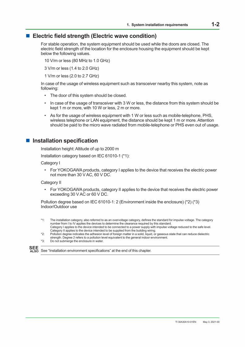
n Electric field strength (Electric wave condition)For stable operation, the system equipment should be used while the doors are closed. The electric field strength of the location for the enclosure housing the equipment should be kept below the following values.
10 V/m or less (80 MHz to 1.0 GHz)
3 V/m or less (1.4 to 2.0 GHz)
1 V/m or less (2.0 to 2.7 GHz)
In case of the usage of wireless equipment such as transceiver nearby this system, note as following:
• The door of this system should be closed.
• In case of the usage of transceiver with 3 W or less, the distance from this system should be kept 1 m or more, with 10 W or less, 2 m or more.
• As for the usage of wireless equipment with 1 W or less such as mobile-telephone, PHS, wireless telephone or LAN equipment, the distance should be kept 1 m or more. Attention should be paid to the micro wave radiated from mobile-telephone or PHS even out of usage.
n Installation specificationInstallation height: Altitude of up to 2000 m Installation category based on IEC 61010-1 (*1):Category I
• For YOKOGAWA products, category I applies to the device that receives the electric power not more than 30 V AC, 60 V DC.
Category II• For YOKOGAWA products, category II applies to the device that receives the electric power
exceeding 30 V AC or 60 V DC.
Pollution degree based on IEC 61010-1: 2 (Environment inside the enclosure) (*2) (*3) Indoor/Outdoor use
*1: The installation category, also referred to as an overvoltage category, defines the standard for impulse voltage. The category number from I to IV applies the devices to determine the clearance required by this standard.
Category I applies to the device intended to be connected to a power supply with impulse voltage reduced to the safe level. Category II applies to the device intended to be supplied from the building wiring.
*2: Pollution degree indicates the adhesion level of foreign matter in a solid, liquid, or gaseous state that can reduce dielectric strength. Degree 2 refers to a pollution level equivalent to the general indoor environment.
*3: Do not submerge the enclosure in water.
SEE ALSO See “Installation environment specifications” at the end of this chapter.
May 3, 2021-00
1. System installation requirements 1-3
TI 30A30A10-01EN
n Measurement categoriesRegarding the measurement inputs, the following requirements must be satisfied to meet the specifications for the device:The category of the equipment applies to O (Other) in the following table.The rated transient overvoltage is 1500 V.Note: Do not use the equipment for measurements within measurement categories II, III and IV.
Table Measurement category
Applicable standardDescription
IEC/EN/CSA 61010-2-030O (Other) For measurements performed on circuits not directly connected to MAINS.
Measurement category II For measurements performed on circuits directly connected to the low voltage installation.
Measurement category III For measurements performed in the building installation.Measurement category IV For measurements performed at the source of the low-voltage installation.
n Applied standardsSEE ALSO For the applicable standards for the N-IO field enclosure, refer to the following GS.
For CENTUM VP, “N-IO field enclosure” (GS 33J62R10-01EN) For ProSafe-RS, “ N-IO field enclosure” (GS 32P06Q10-01EN)
SEE ALSO For the standards for hazardous location equipment, refer to the following TI.
For CENTUM VP, “Explosion Protection” (TI 33Q01J30-01E) For ProSafe-RS, “Explosion Protection (for ProSafe-RS)” (TI 32S01J30-01E)
Mar. 27, 2020-00
1. System installation requirements 1-4
TI 30A30A10-01EN
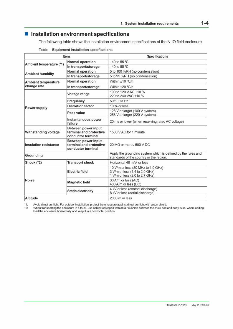
n Installation environment specificationsThe following table shows the installation environment specifications of the N-IO field enclosure.
Table Equipment installation specifications
Item Specifications
Ambient temperature (*1) Normal operation –40 to 55 ºCIn transport/storage –40 to 85 ºC
Ambient humidity Normal operation 5 to 100 %RH (no condensation)In transport/storage 5 to 95 %RH (no condensation)
Ambient temperaturechange rate
Normal operation Within ±10 ºC/hIn transport/storage Within ±20 ºC/h
Power supply
Voltage range 100 to 120 V AC ±10 %220 to 240 VAC ±10 %
Frequency 50/60 ±3 HzDistortion factor 10 % or less
Peak value 128 V or larger (100 V system)258 V or larger (220 V system)
Instantaneous power failure 20 ms or lower (when receiving rated AC voltage)
Withstanding voltage Between power input terminal and protective conductor terminal
1500 V AC for 1 minute
Insulation resistance Between power input terminal and protective conductor terminal
20 MΩ or more / 500 V DC
Grounding Apply the grounding system which is defined by the rules and standards of the country or the region.
Shock (*2) Transport shock Horizontal 48 m/s2 or less
Noise
Electric field10 V/m or less (80 MHz to 1.0 GHz)3 V/m or less (1.4 to 2.0 GHz)1 V/m or less (2.0 to 2.7 GHz)
Magnetic field 30 A/m or less (AC)400 A/m or less (DC)
Static electricity 4 kV or less (contact discharge) 8 kV or less (aerial discharge)
Altitude 2000 m or less
*1: Avoid direct sunlight. For outdoor installation, protect the enclosure against direct sunlight with a sun shield.*2: When transporting the enclosure in a truck, use a truck equipped with an air cushion between the truck bed and body. Also, when loading,
load the enclosure horizontally and keep it in a horizontal position.
May 18, 2018-00
1. System installation requirements 1-5
TI 30A30A10-01EN
1.2 Power supply systemTo stable system operation, the following conditions should be met:
• Voltage and frequency fluctuations are within the limits specified for each system component.
• Relationship between the waveform’s effective values and peak value is within the specified range.
• High-frequency noise is not at a level that affects system operation.
• Use an UPS (uninterruptible power supply) if necessary.
n AC Power specificationAC power used for the system must satisfied rated voltage and the peak value must be greater than the minimum specified (see below).
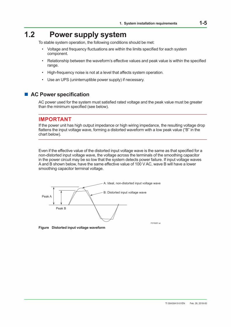
IMPORTANTIf the power unit has high output impedance or high wiring impedance, the resulting voltage drop flattens the input voltage wave, forming a distorted waveform with a low peak value (“B” in the chart below).
Even if the effective value of the distorted input voltage wave is the same as that specified for a non-distorted input voltage wave, the voltage across the terminals of the smoothing capacitor in the power circuit may be so low that the system detects power failure. If input voltage waves A and B shown below, have the same effective value of 100 V AC, wave B will have a lower smoothing capacitor terminal voltage.
Peak A
Peak B
F010201.ai
A: Ideal, non-distorted input voltage wave
B: Distorted input voltage wave
Figure Distorted input voltage waveform
Feb. 26, 2018-00
1. System installation requirements 1-6
TI 30A30A10-01EN
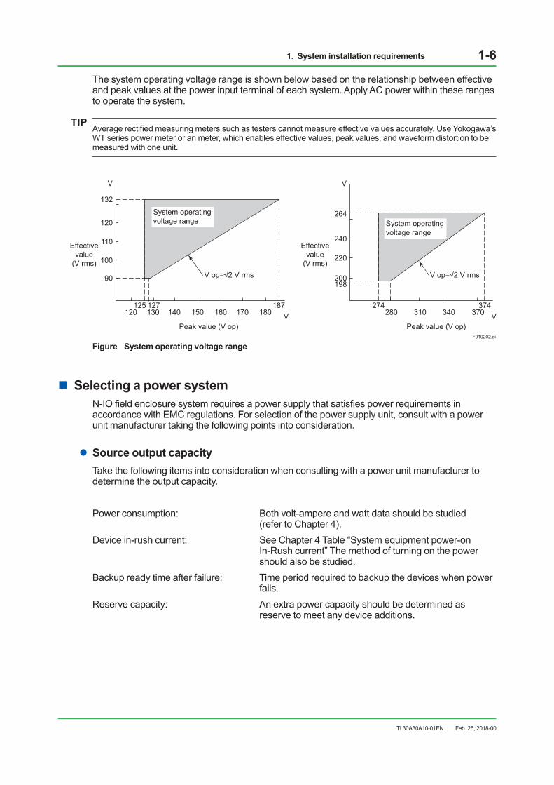
The system operating voltage range is shown below based on the relationship between effective and peak values at the power input terminal of each system. Apply AC power within these ranges to operate the system.
TIP Average rectified measuring meters such as testers cannot measure effective values accurately. Use Yokogawa’s WT series power meter or an meter, which enables effective values, peak values, and waveform distortion to be measured with one unit.
120125 127
90
100
110
120
132
130 140 150 160 170187
Peak value (V op)V
V
Effectivevalue
(V rms)
Effectivevalue
(V rms)
System operating voltage range
F010202.ai
274
200198
220
240
264
280 310 340 370374
Peak value (V op)V
V
180
System operating voltage range
V op= 2 V rms V op= 2 V rms
Figure System operating voltage range
n Selecting a power systemN-IO field enclosure system requires a power supply that satisfies power requirements in accordance with EMC regulations. For selection of the power supply unit, consult with a power unit manufacturer taking the following points into consideration.
lSource output capacityTake the following items into consideration when consulting with a power unit manufacturer to determine the output capacity.
Power consumption: Both volt-ampere and watt data should be studied (refer to Chapter 4).Device in-rush current: See Chapter 4 Table “System equipment power-on In-Rush current” The method of turning on the power should also be studied.Backup ready time after failure: Time period required to backup the devices when power fails.Reserve capacity: An extra power capacity should be determined as reserve to meet any device additions.
Feb. 26, 2018-00
1. System installation requirements 1-7
TI 30A30A10-01EN
lIn-Rush currentWhen the equipment is turned on, a large in-rush current flows as the capacitor is instantaneously charged and the transformer is excited. When any equipment is turned on, this should not cause any voltage fluctuation that could adversely affect other equipment. Do not turn on all equipment at the same time. Start equipment one by one. Power may be switched to backup or AC line power if in-rush current activates the overload protection circuit on power-up. After such an overload, select an uninterruptible power unit, with automatic-recovery.
n CablingObserve the following when cabling the power unit to the system equipment:
• Protect signal cables from induced noise.
• Protect signal cables from induced noise from high-voltage power lines.
• Separate the system power supply from other equipment power supplies using a power distribution board.
• Provide a dedicated breaker for each power supply.
• Label the breakers with the name of the connected equipment.
• Install the breakers where they can be easily operated.
• The breaker, must not interrupt connection by wiring to protective grounding system.
• Install power supply cables and high-voltage power lines in metallic conduits as much as possible.
• Use shielded cables if metallic conduits cannot be provided.
June 30, 2016-00
1. System installation requirements 1-8
TI 30A30A10-01EN
1.3 GroundingTo avoid electric shocks and minimize the influences of external noise, the installed devices must be grounded to the protective grounding system which complies with the safety standards, the electrical installations standard, and the power distribution system of the country or the region. As for the protective grounding systems, the meshed grounding systems described in IEC 60364, IEC 62305 and IEC 61000-5-2 can be applied. A protective device is to be installed in compliance with the rules and regulations, in order to prevent electric shocks caused by a ground fault.
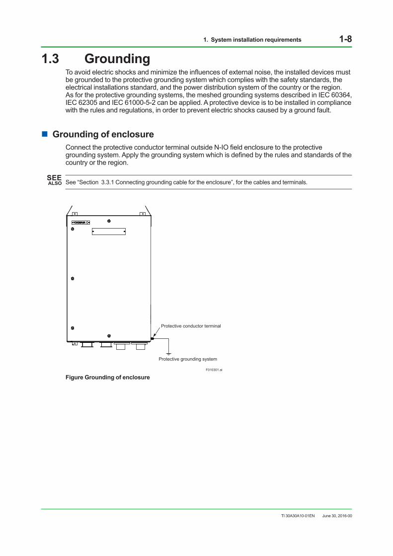
n Grounding of enclosureConnect the protective conductor terminal outside N-IO field enclosure to the protective grounding system. Apply the grounding system which is defined by the rules and standards of the country or the region.
SEE ALSO See “Section 3.3.1 Connecting grounding cable for the enclosure”, for the cables and terminals.
F010301.ai
Protective conductor terminal
Protective grounding system
Figure Grounding of enclosure
June 30, 2016-00
1. System installation requirements 1-9
TI 30A30A10-01EN
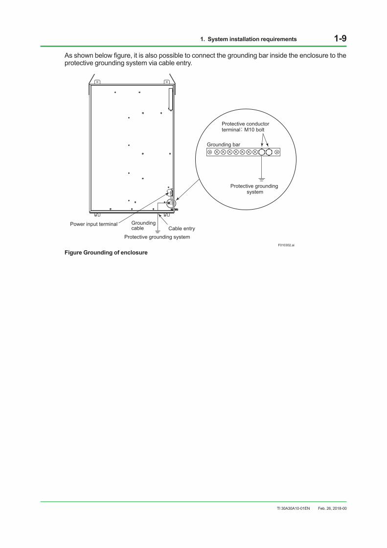
As shown below figure, it is also possible to connect the grounding bar inside the enclosure to the protective grounding system via cable entry.
F010302.ai
Protective conductorterminal: M10 bolt
Grounding bar
Protective grounding system
Protective grounding system
Power input terminalCable entry
Groundingcable
Figure Grounding of enclosure
Feb. 26, 2018-00
1. System installation requirements 1-10
TI 30A30A10-01EN
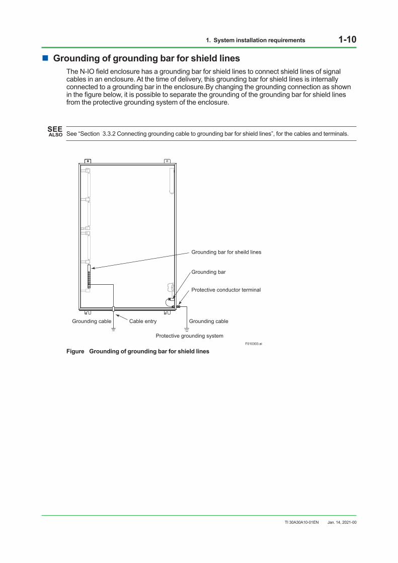
n Grounding of grounding bar for shield linesThe N-IO field enclosure has a grounding bar for shield lines to connect shield lines of signal cables in an enclosure. At the time of delivery, this grounding bar for shield lines is internally connected to a grounding bar in the enclosure.By changing the grounding connection as shown in the figure below, it is possible to separate the grounding of the grounding bar for shield lines from the protective grounding system of the enclosure.
SEE ALSO See “Section 3.3.2 Connecting grounding cable to grounding bar for shield lines”, for the cables and terminals.
Protective grounding systemF010303.ai
Protective conductor terminal
Grounding cableGrounding cable
Grounding bar for sheild lines
Grounding bar
Cable entry
Figure Grounding of grounding bar for shield lines
Jan. 14, 2021-00

1. System installation requirements 1-11
TI 30A30A10-01EN
n Grounding circuitAn enclosure must be grounded according to the grounding network topology of the building or plant for installation. In order to connect an enclosure with a protective grounding system, the grounding topology shown in the figures “Grounding connected to single grounding bus inlet” or “Grounding connected to each grounding bus inlet” can be used. A grounding cable with a cross section of at least 14 mm2 or more that complies with the standards in each country and region should be used between each enclosure and grounding bus inlet. When providing lightning arresters on power and signal lines, those arresters need to be grounded to the same bus. For details, see Section 1.4, “Noise countermeasures.”
Enclosure Enclosure Enclosure Enclosure
Protective grounding system
Graunding bus inlet
F010304.ai
G: Protective conductor terminal
G G G G
Figure Grounding connected to a single grounding bus inlet
Protectivegrounding system
Protectivegrounding system
Protectivegrounding system
Protectivegrounding system
G: Protective conductor terminal
Graunding bus inlet
F010305.ai
G
Enclosure Enclosure Enclosure Enclosure
G G G
Figure Grounding connected to each grounding bus inlet
Jan. 14, 2021-00
1. System installation requirements 1-12
TI 30A30A10-01EN
1.4 Noise countermeasuresNoise may be induced by electromagnetic induction, electrostatic induction, or from radio waves, lightning, inductive loads, static electricity and ground potential differences. It can be picked up by power, signal and grounding cables, and devices. With computerized control systems, noise-induced errors in A/D conversion or in an instruction word may lead to malfunction.To prevent noise and electrostatic buildup, take the measures described in this section in deciding cable type, cable routing, and grounding.
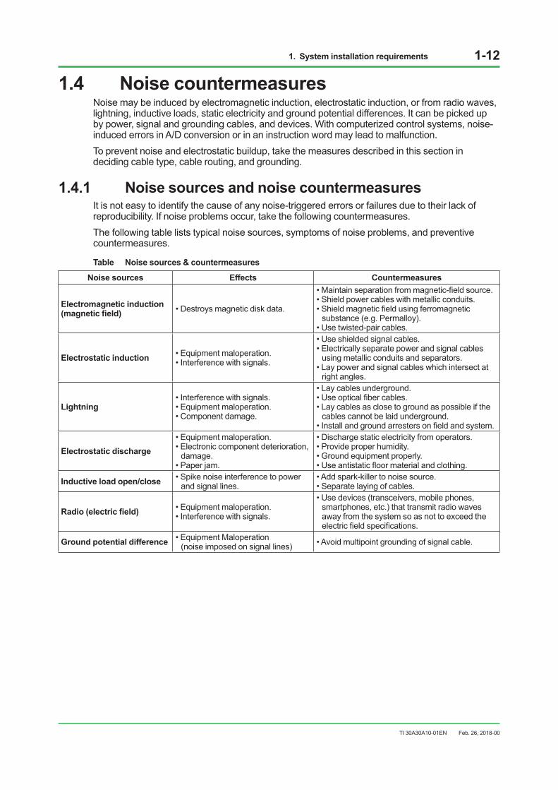
1.4.1 Noise sources and noise countermeasuresIt is not easy to identify the cause of any noise-triggered errors or failures due to their lack of reproducibility. If noise problems occur, take the following countermeasures.The following table lists typical noise sources, symptoms of noise problems, and preventive countermeasures.
Table Noise sources & countermeasures
Noise sources Effects Countermeasures
Electromagnetic induction (magnetic field) • Destroys magnetic disk data.
• Maintain separation from magnetic-field source. • Shield power cables with metallic conduits. • Shield magnetic field using ferromagnetic
substance (e.g. Permalloy).• Use twisted-pair cables.
Electrostatic induction • Equipment maloperation.• Interference with signals.
• Use shielded signal cables. • Electrically separate power and signal cables
using metallic conduits and separators.• Lay power and signal cables which intersect at
right angles.
Lightning • Interference with signals. • Equipment maloperation.• Component damage.
• Lay cables underground. • Use optical fiber cables. • Lay cables as close to ground as possible if the
cables cannot be laid underground.• Install and ground arresters on field and system.
Electrostatic discharge • Equipment maloperation. • Electronic component deterioration,
damage.• Paper jam.
• Discharge static electricity from operators. • Provide proper humidity.• Ground equipment properly. • Use antistatic floor material and clothing.
Inductive load open/close • Spike noise interference to power and signal lines.
• Add spark-killer to noise source. • Separate laying of cables.
Radio (electric field) • Equipment maloperation. • Interference with signals.
• Use devices (transceivers, mobile phones, smartphones, etc.) that transmit radio waves away from the system so as not to exceed the electric field specifications.
Ground potential difference • Equipment Maloperation (noise imposed on signal lines) • Avoid multipoint grounding of signal cable.
Feb. 26, 2018-00
1. System installation requirements 1-13
TI 30A30A10-01EN
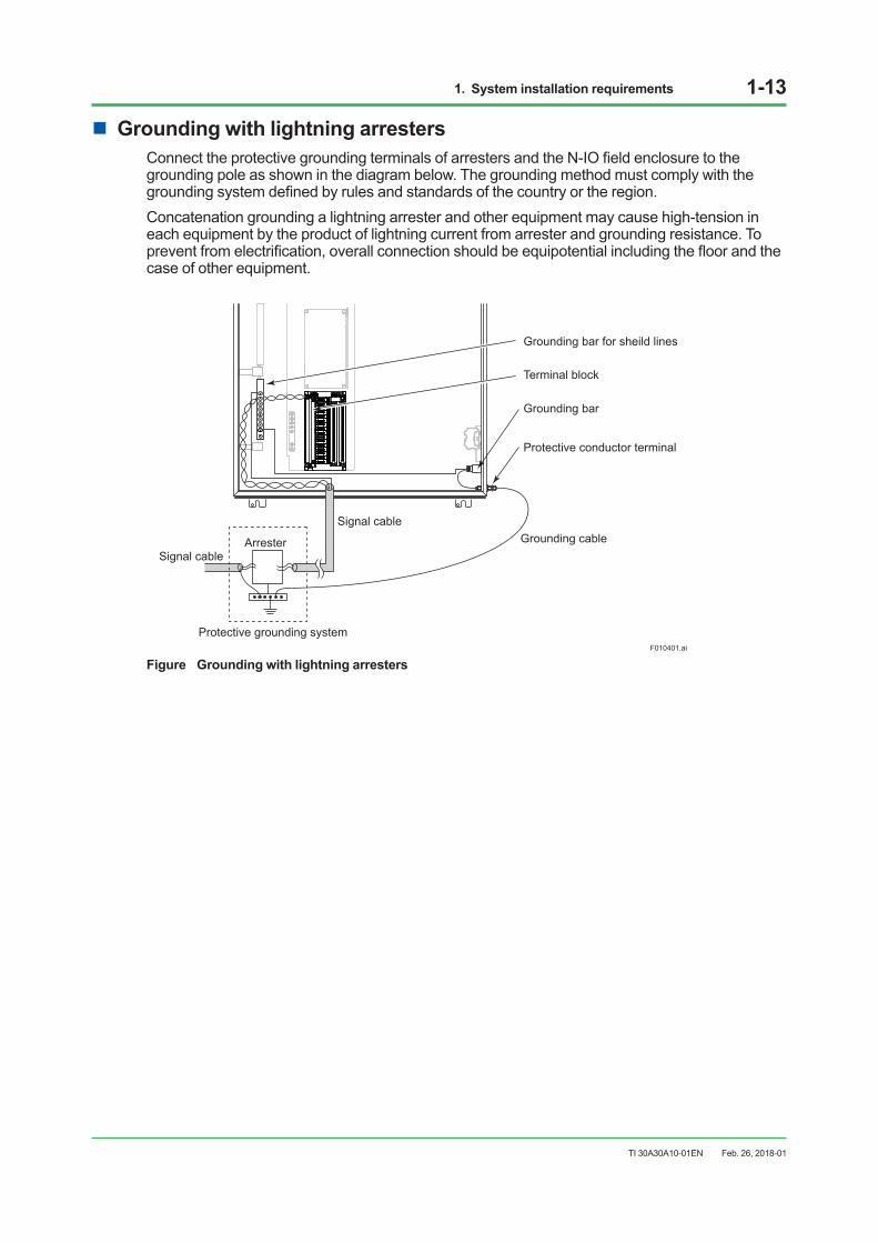
n Grounding with lightning arrestersConnect the protective grounding terminals of arresters and the N-IO field enclosure to the grounding pole as shown in the diagram below. The grounding method must comply with the grounding system defined by rules and standards of the country or the region.Concatenation grounding a lightning arrester and other equipment may cause high-tension in each equipment by the product of lightning current from arrester and grounding resistance. To prevent from electrification, overall connection should be equipotential including the floor and the case of other equipment.
Protective grounding systemF010401.ai
Signal cable
Signal cable
Protective conductor terminal
Grounding bar for sheild lines
Terminal block
Grounding bar
Arrester Grounding cable
Figure Grounding with lightning arresters
Feb. 26, 2018-01
1. System installation requirements 1-14
TI 30A30A10-01EN
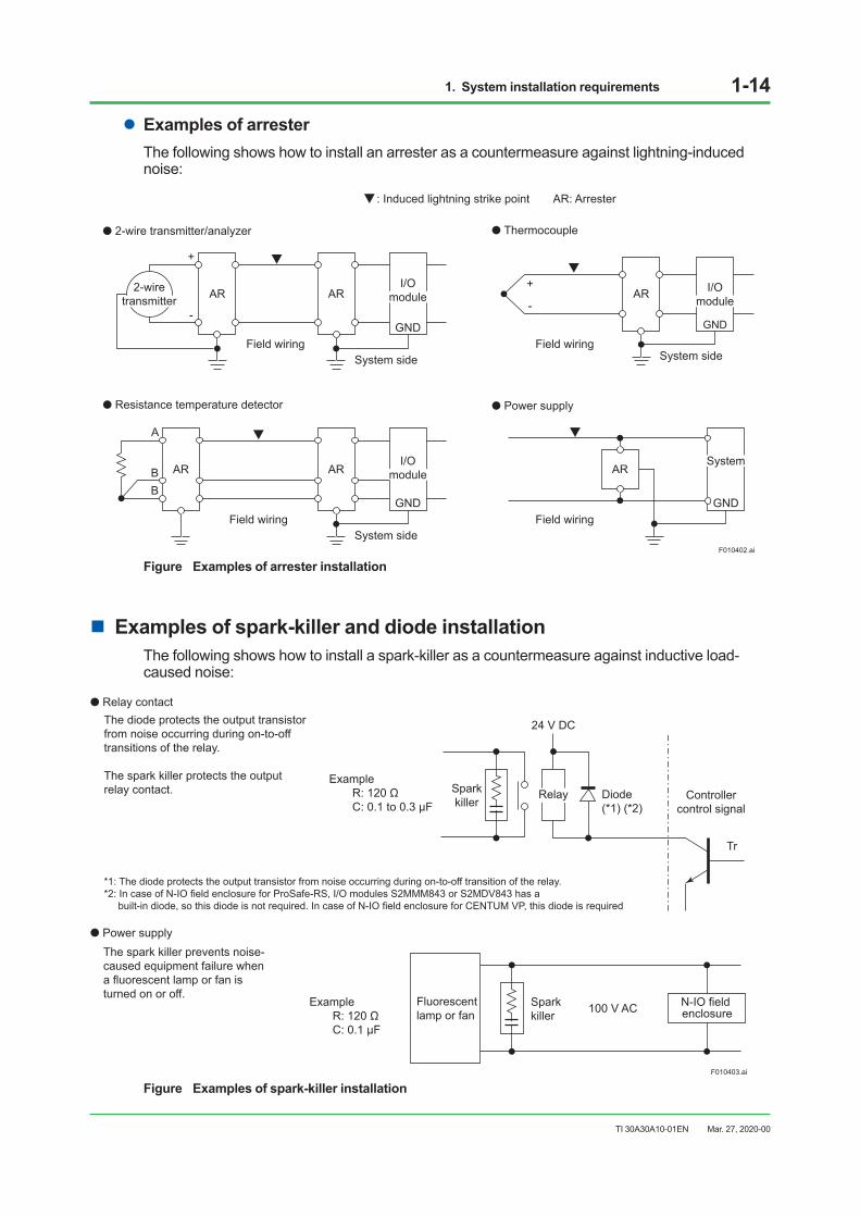
lExamples of arresterThe following shows how to install an arrester as a countermeasure against lightning-induced noise:
GND
I/Omodule
AR ARI/O
module
GND
System sideField wiring
+
-
AR AR
System sideField wiring
A
BB
I/Omodule
GND
AR
System sideField wiring
+
-
AR
Field wiring
: Induced lightning strike point AR: Arrester
F010402.ai
2-wire transmitter/analyzer
Resistance temperature detector
Thermocouple
Power supply
GND
System
2-wiretransmitter
Figure Examples of arrester installation
n Examples of spark-killer and diode installationThe following shows how to install a spark-killer as a countermeasure against inductive load-caused noise:
Relay contact
Power supply
F010403.ai
Example R: 120 ΩC: 0.1 to 0.3 μF
Example R: 120 ΩC: 0.1 μF
Spark killer
N-IO field enclosure100 V AC Fluorescent
lamp or fan
The spark killer prevents noise- caused equipment failure when a fluorescent lamp or fan is turned on or off.
The diode protects the output transistorfrom noise occurring during on-to-offtransitions of the relay.
The spark killer protects the output relay contact.
*1: The diode protects the output transistor from noise occurring during on-to-off transition of the relay.*2: In case of N-IO field enclosure for ProSafe-RS, I/O modules S2MMM843 or S2MDV843 has a built-in diode, so this diode is not required. In case of N-IO field enclosure for CENTUM VP, this diode is required
Diode(*1) (*2)
Controllercontrol signal
Sparkkiller
24 V DC
Tr
Relay
Figure Examples of spark-killer installation
Mar. 27, 2020-00
1. System installation requirements 1-15
TI 30A30A10-01EN
1.4.2 Countermeasures against static electricityTake countermeasures against electrostatic damage when handling cards with semi-conductor IC components, for maintenance or to change settings.Observe the following to prevent electrostatic damage:
• When storing or carrying maintenance parts, be sure to enclose them in an antistatic bag. (For shipment these parts are enclosed in an antistatic bag labeled with precautions against electrostatic charge.)
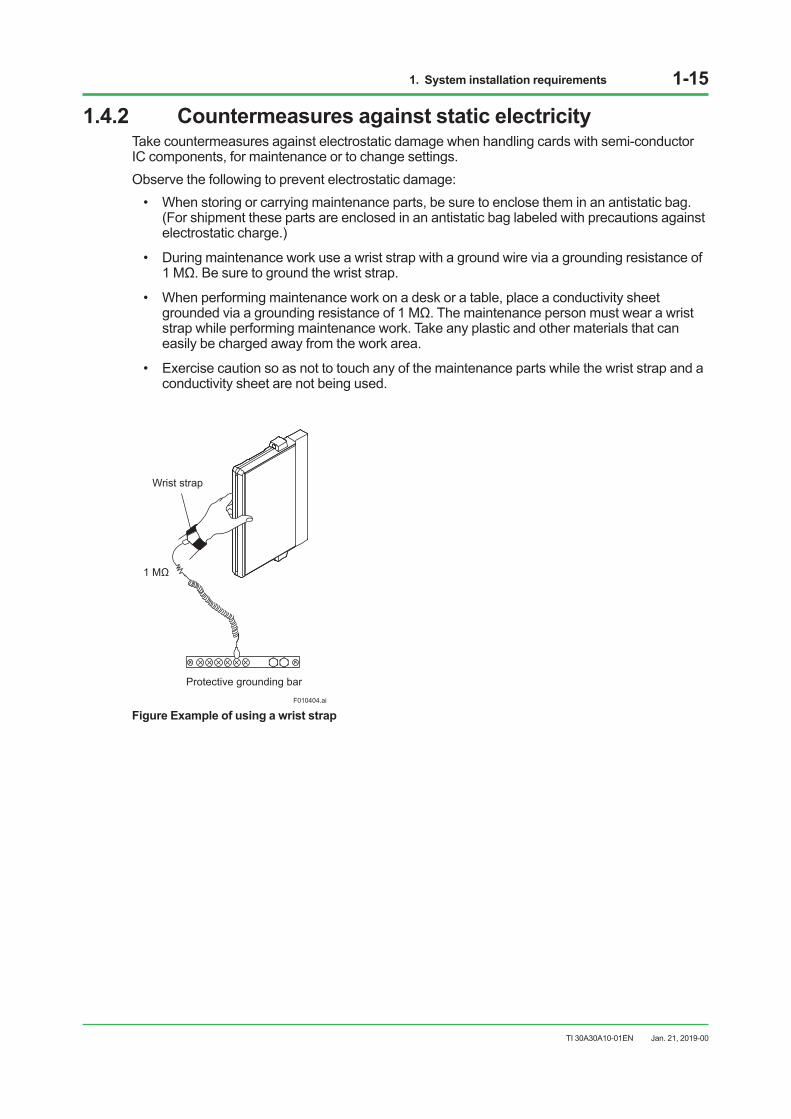
• During maintenance work use a wrist strap with a ground wire via a grounding resistance of 1 MΩ. Be sure to ground the wrist strap.
• When performing maintenance work on a desk or a table, place a conductivity sheet grounded via a grounding resistance of 1 MΩ. The maintenance person must wear a wrist strap while performing maintenance work. Take any plastic and other materials that can easily be charged away from the work area.
• Exercise caution so as not to touch any of the maintenance parts while the wrist strap and a conductivity sheet are not being used.
F010404.ai
Protective grounding bar
1 MΩ
Wrist strap
Figure Example of using a wrist strap
Jan. 21, 2019-00
1. System installation requirements 1-16
TI 30A30A10-01EN
1.5 Cabling requirementsThe following requirements must be fulfilled when laying power and signal cables.Any signal cable used for high-voltage, high-frequency signals (inductive load ON/ OFF) must be separated from other signal cables.
n SeparatorProvide a separator between power and signal cables as illustrated below:
Signal cables
Power cables
Separator (steel plate)
Protective grounding system(different from the system grounding for the enclosure)
F010501.ai
Figure Separator used in duct/pit
n Distance between cablesIf a separator cannot be used, keep a distance between signal cables and power cables. The distances between cables due to operating voltages and currents are shown below.
Table Required distance between Power & Shielded signal cables
Operating voltage Operating current Distance 240 V AC max. 10 A max. 150 mm min. 240 V AC max. 10 A min. 600 mm min. 240 V AC min. 10 A max. 600 mm min. 240 V AC min. 10 A min. Cannot be laid together.
Power cables
F010502.ai
150 mm or more
Signal cablesSignal cables Power cables
150 mmor more
Figure Distance between cables under pit/free-access floor
Jan. 14, 2021-00
1. System installation requirements 1-17
TI 30A30A10-01EN
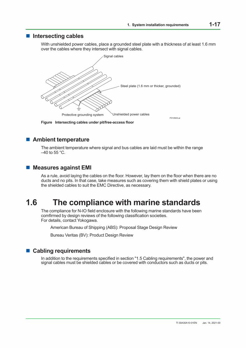
n Intersecting cablesWith unshielded power cables, place a grounded steel plate with a thickness of at least 1.6 mm over the cables where they intersect with signal cables.
Signal cables
Steel plate (1.6 mm or thicker, grounded)
Unshielded power cablesProtective grounding systemF010503.ai
Figure Intersecting cables under pit/free-access floor
n Ambient temperatureThe ambient temperature where signal and bus cables are laid must be within the range –40 to 55 °C.
n Measures against EMIAs a rule, avoid laying the cables on the floor. However, lay them on the floor when there are no ducts and no pits. In that case, take measures such as covering them with shield plates or using the shielded cables to suit the EMC Directive, as necessary.
1.6 The compliance with marine standardsThe compliance for N-IO field enclosure with the following marine standards have been comfirmed by design reviews of the following classification societies. For details, contact Yokogawa.
American Bureau of Shipping (ABS): Proposal Stage Design Review
Bureau Veritas (BV): Product Design Review
n Cabling requirementsIn addition to the requirements specified in section "1.5 Cabling requirements", the power and signal cables must be shielded cables or be covered with conductors such as ducts or pits.
Jan. 14, 2021-00
2. Transportation, storage and installation 2-1
TI 30A30A10-01EN
2. Transportation, storage and installation
This chapter describes the precautions in transporting, storing, and installing the N-IO field enclosure.
SEE ALSO See “Section 1.1 Installation environment” for the environmental requirement for each piece of equipment.
2.1 Precautions for transportationThis section describes the precautions required to transport the N-IO field enclosure. It is intended to prevent accidents caused by transportation. These precautions apply when the equipment is contained in our original packing.
n TransportationSEE ALSO See “Table Equipment installation specifications” in Section 1.1 Installation environment for ambient temperature,
humidity and impact.
lLoading• Load crates horizontally.
• When loading crates on top of others, up to the following number of stacking stages is allowable.
Table Allowable total number of stacking stages
Model Allowable total number of stacking stagesA2NN70D, S2NN70D Total 3 stagesA2NN60D, S2NN60D Total 4 stages
A2CB60, S2CB60 Total 3 stages
• Keep all crates upright.
• Secure loaded crates using ropes, and cover them completely with waterproof coverings.
• Do not load crates outdoors when it is raining.
lDon’t stack outdoorsBe sure to store cargoes inside a warehouse if they must be stored for some time.
Feb. 26, 2018-00
2. Transportation, storage and installation 2-2
TI 30A30A10-01EN
lTransportationThe N-IO field enclosure is a precision device. Select a company specializing in the transportation of computers and precision instruments. Keep all products horizontally during air transport, freightage, or truck transport. When transporting by track, drive at low speed to avoid vibration and impact. Also, slow down to the limit on a bad road.
lOthersDo not transport equipment through areas where there may be corrosive gas, intense electric or magnetic fields.
n UnloadingPrepare special equipment for unloading. Avoid unloading outdoor in case of rain.
lLocation for unloadingTo select a location for safe unloading, check that:
• There is ample space for crane and forklift maneuvering.
• Ground is solid.
• The handrails of scaffold can be removed.
• There is enough working space for unpacking (at least 2500 mm by 4000 mm). Provide a platform if necessary.
• Outdoor-indoor temperature difference should be less than 10 °C to avoid condensation.
lKeep uprightKeep crates upright when unloading.
lAvoid physical shockAvoid physical shock. Be careful not to lose balance or swing when lifting or placing cargoes on the ground or platform. Also check scaffold strength.
Feb. 26, 2018-00
2. Transportation, storage and installation 2-3
TI 30A30A10-01EN
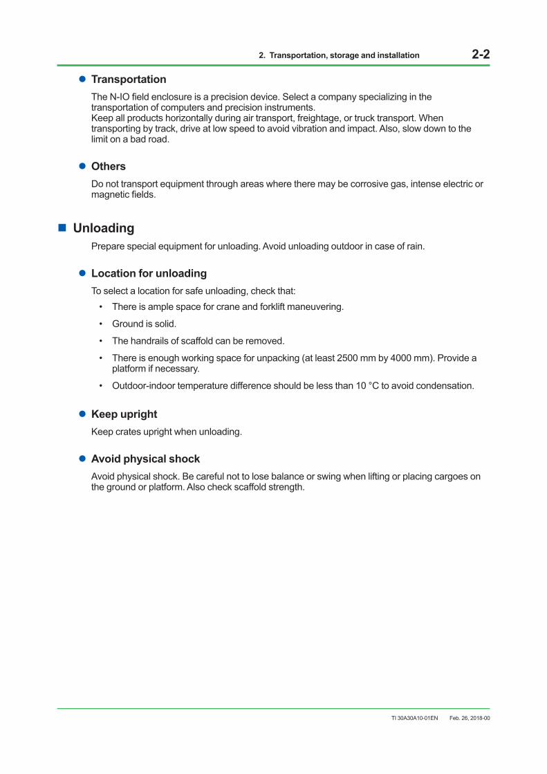
lLifting an N-IO field enclosureWhen lifting an N-IO field enclosure by a crane, follow the instructions below.
• The N-IO field enclosure has two pad eyes on the top surface of the enclosure to lift it by a crane. Use a wire rope for each pad eye.
• Keep the lifting angle of about 60 degrees.
• The wire or the crane must have enough strength against the product weights.
F020101.ai
Pad eye
60°
Figure How to lift of an enclosure
n CarryingThis section describes how to carry enclosures.
lCarrying space, passageCarry enclosures into the location of installation without unpacking. Determine the passage according to the product’s packing size and weight and carrier’s size and weight.
Table Packing size and packing weight of the product
Model Packing size (mm) Packing weight (kg) (*1)A2NN70D, S2NN70D 1020 (D) x 1510 (W) x 560 (H) Product weight + 11.2A2NN60D, S2NN60D 863 (D) x 1225 (W) x 490 (H) Product weight + 10.0A2CB60, S2CB60 1020 (D) x 1510 (W) x 560 (H) Product weight + 11.2
*1: For product weight, refer to “n STANDARD SPECIFICATIONS” in the General Specifications (GS) of each product.
Mar. 27, 2020-00
2. Transportation, storage and installation 2-4
TI 30A30A10-01EN
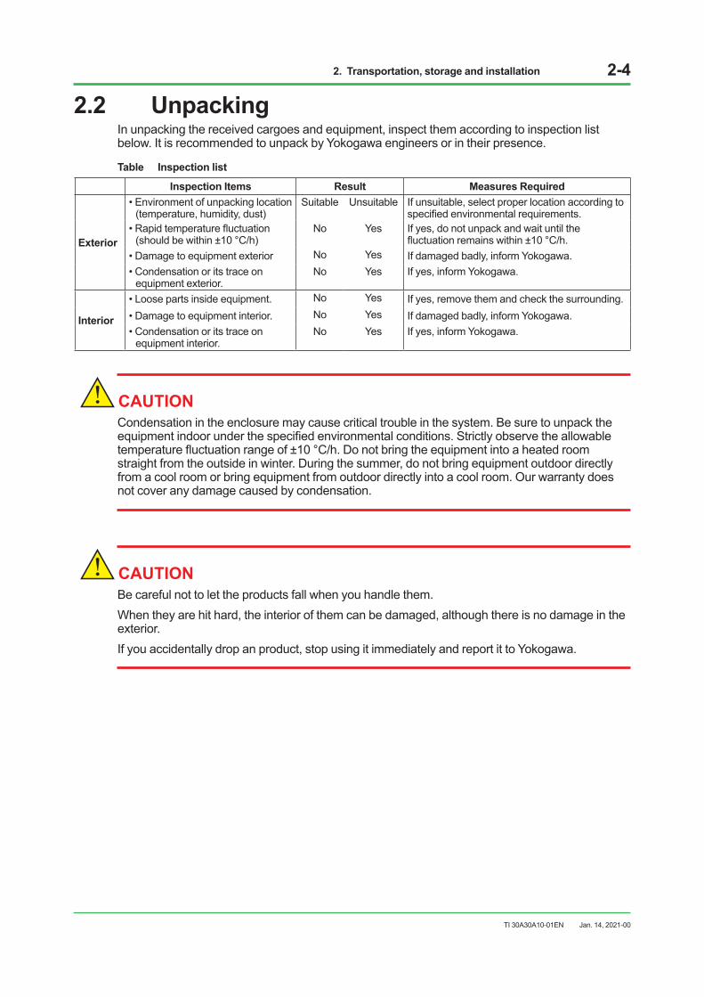
2.2 UnpackingIn unpacking the received cargoes and equipment, inspect them according to inspection list below. It is recommended to unpack by Yokogawa engineers or in their presence.
Table Inspection list
Inspection Items Result Measures Required
Exterior
• Environment of unpacking location (temperature, humidity, dust)
Suitable Unsuitable If unsuitable, select proper location according to specified environmental requirements.
• Rapid temperature fluctuation (should be within ±10 °C/h)
No Yes If yes, do not unpack and wait until the fluctuation remains within ±10 °C/h.
• Damage to equipment exterior No Yes If damaged badly, inform Yokogawa. • Condensation or its trace on
equipment exterior.No Yes If yes, inform Yokogawa.
Interior
• Loose parts inside equipment. No Yes If yes, remove them and check the surrounding. • Damage to equipment interior. No Yes If damaged badly, inform Yokogawa. • Condensation or its trace on
equipment interior.No Yes If yes, inform Yokogawa.
CAUTIONCondensation in the enclosure may cause critical trouble in the system. Be sure to unpack the equipment indoor under the specified environmental conditions. Strictly observe the allowable temperature fluctuation range of ±10 °C/h. Do not bring the equipment into a heated room straight from the outside in winter. During the summer, do not bring equipment outdoor directly from a cool room or bring equipment from outdoor directly into a cool room. Our warranty does not cover any damage caused by condensation.
CAUTIONBe careful not to let the products fall when you handle them.When they are hit hard, the interior of them can be damaged, although there is no damage in the exterior.If you accidentally drop an product, stop using it immediately and report it to Yokogawa.
Jan. 14, 2021-00
2. Transportation, storage and installation 2-5
TI 30A30A10-01EN
2.3 StorageThe delivery date should be determined in accordance with your installation schedule. Avoid storing products more than three months. If long-term storage more than three months cannot be avoided, consult Yokogawa in advance because it is necessary to provide waterproofing, condensation prevention, and dustproofing measures as well as periodical inspections.
n Storage conditionStore products without unpacking. Be sure to confirm that the crate is not damaged. To store them after unpacking, be sure to take the precautions described below.
n Location of storageStore products in a warehouse or indoor facilities - never in an open-air location.
n Storage environment• Ambient Temperature for storage: -40 to 85 °C
• Avoid direct sunlight.
• Prevent wet with water.
• Prevent condensation.
• Do not store products where corrosive gas or salty air may be present.
SEE ALSO See “Section 1.1 Installation environment” for permissible temperature, humidity and temperature fluctuation of
storage area.
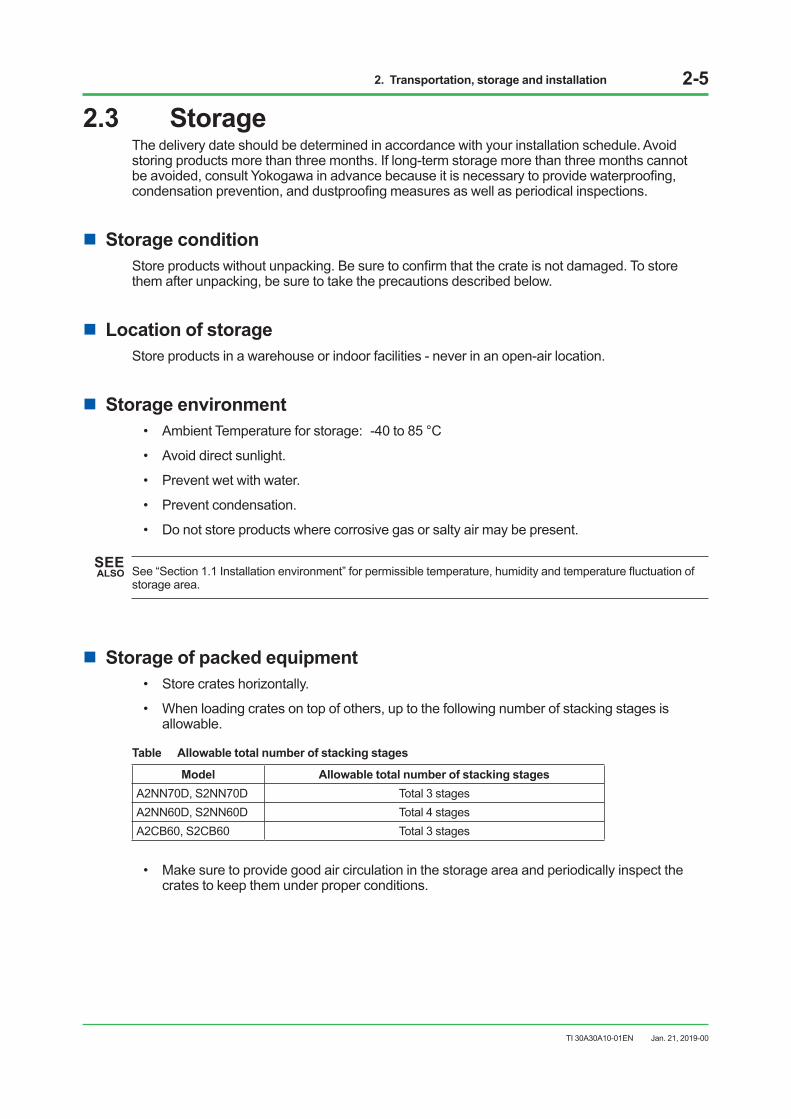
n Storage of packed equipment• Store crates horizontally.
• When loading crates on top of others, up to the following number of stacking stages is allowable.
Table Allowable total number of stacking stages
Model Allowable total number of stacking stagesA2NN70D, S2NN70D Total 3 stagesA2NN60D, S2NN60D Total 4 stagesA2CB60, S2CB60 Total 3 stages
• Make sure to provide good air circulation in the storage area and periodically inspect the crates to keep them under proper conditions.
Jan. 21, 2019-00
2. Transportation, storage and installation 2-6
TI 30A30A10-01EN
n Storage of unpacked equipmentTo store unpacked products without power connection, follow the specified environmental requirements. If stored in a non-air-conditioned room, cover them with polyethylene or other sheets for protection against dust and moisture. For moisture-proofing, place a sufficient amount of Silica gel or other desiccating agent inside the covering and inspect replace from time to time.When using desiccating agent or corrosion inhibitor etc., please select the appropriate one. Also, please make sure that it does not affect the function and performance of the product before actually using it.
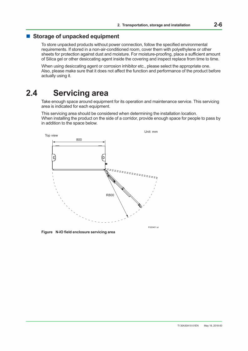
2.4 Servicing areaTake enough space around equipment for its operation and maintenance service. This servicing area is indicated for each equipment.This servicing area should be considered when determining the installation location. When installing the product on the side of a corridor, provide enough space for people to pass by in addition to the space below.
F020401.ai
R800
Unit: mm
800Top view
Figure N-IO field enclosure servicing area
May 18, 2018-00
2. Transportation, storage and installation 2-7
TI 30A30A10-01EN
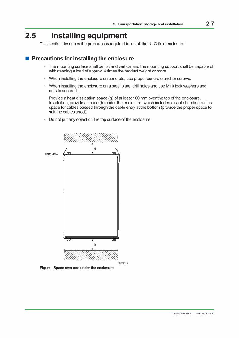
2.5 Installing equipmentThis section describes the precautions required to install the N-IO field enclosure.
n Precautions for installing the enclosure• The mounting surface shall be flat and vertical and the mounting support shall be capable of
withstanding a load of approx. 4 times the product weight or more.
• When installing the enclosure on concrete, use proper concrete anchor screws.
• When installing the enclosure on a steel plate, drill holes and use M10 lock washers and nuts to secure it.
• Provide a heat dissipation space (g) of at least 100 mm over the top of the enclosure. In addition, provide a space (h) under the enclosure, which includes a cable bending radius space for cables passed through the cable entry at the bottom (provide the proper space to suit the cables used).
• Do not put any object on the top surface of the enclosure.
F020501.ai
Front view
g
h
Figure Space over and under the enclosure
Feb. 26, 2018-00
3. Cabling 3-1
TI 30A30A10-01EN
3. CablingThis section describes how to cable the installed system equipment. Connecting terminals for power, grounding, signal, and communication cables are shown in figures.
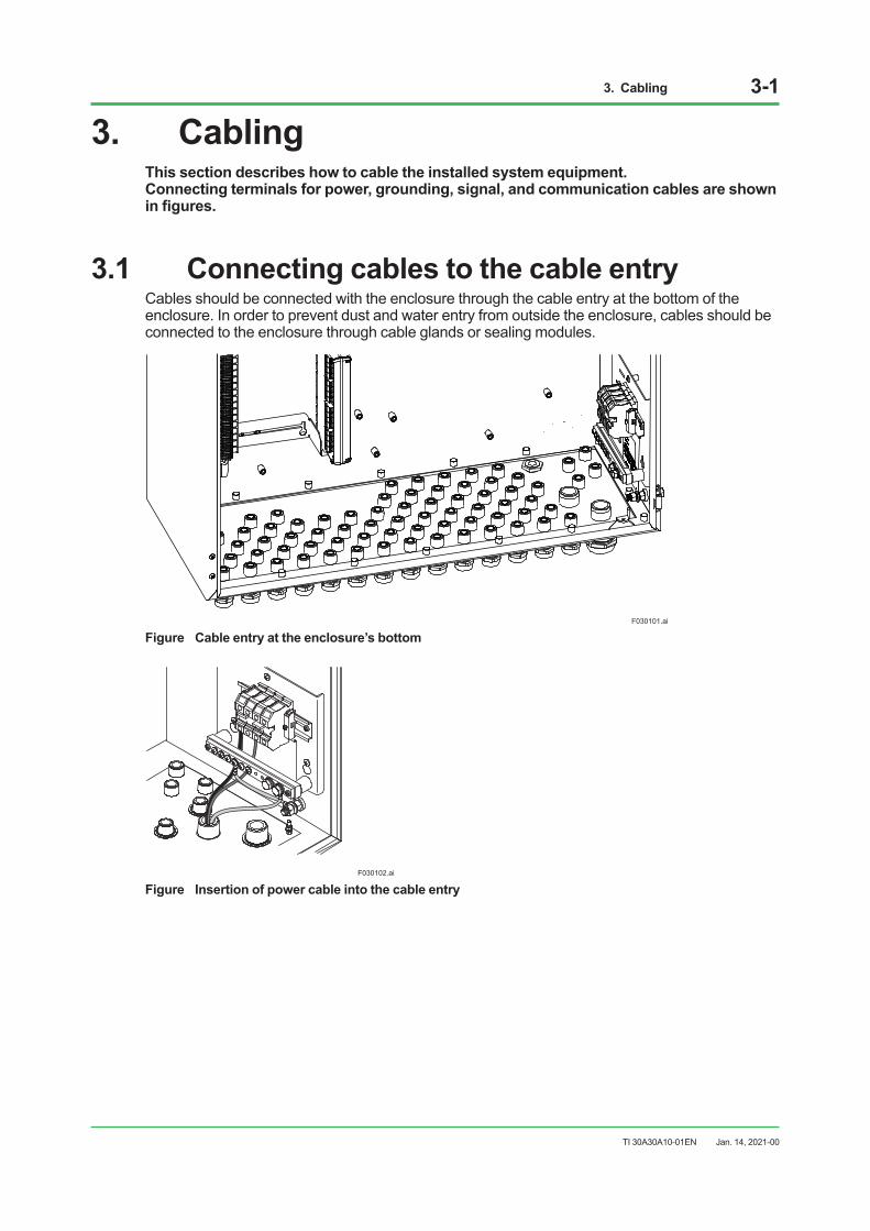
3.1 Connecting cables to the cable entryCables should be connected with the enclosure through the cable entry at the bottom of the enclosure. In order to prevent dust and water entry from outside the enclosure, cables should be connected to the enclosure through cable glands or sealing modules.
F030101.ai
Figure Cable entry at the enclosure’s bottom
F030102.ai
Figure Insertion of power cable into the cable entry
Jan. 14, 2021-00
3. Cabling 3-2
TI 30A30A10-01EN
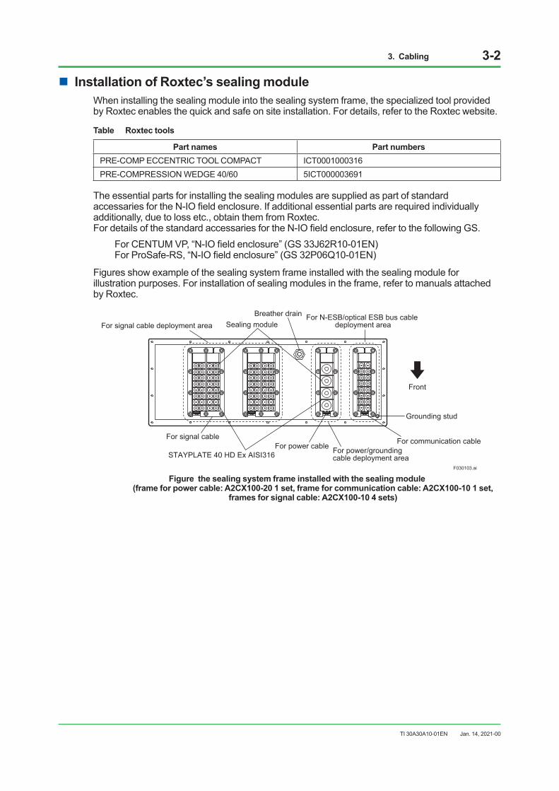
n Installation of Roxtec’s sealing moduleWhen installing the sealing module into the sealing system frame, the specialized tool provided by Roxtec enables the quick and safe on site installation. For details, refer to the Roxtec website.
Table Roxtec tools
Part names Part numbersPRE-COMP ECCENTRIC TOOL COMPACT ICT0001000316PRE-COMPRESSION WEDGE 40/60 5ICT000003691
The essential parts for installing the sealing modules are supplied as part of standard accessaries for the N-IO field enclosure. If additional essential parts are required individually additionally, due to loss etc., obtain them from Roxtec. For details of the standard accessaries for the N-IO field enclosure, refer to the following GS.
For CENTUM VP, “N-IO field enclosure” (GS 33J62R10-01EN) For ProSafe-RS, “N-IO field enclosure” (GS 32P06Q10-01EN)
Figures show example of the sealing system frame installed with the sealing module for illustration purposes. For installation of sealing modules in the frame, refer to manuals attached by Roxtec.
F030103.ai
Breather drain
For power cable For communication cableFor signal cable
STAYPLATE 40 HD Ex AISI316
For N-ESB/optical ESB bus cable deployment area
Front
For signal cable deployment area
For power/grounding cable deployment area
Grounding stud
Sealing module
Figure the sealing system frame installed with the sealing module (frame for power cable: A2CX100-20 1 set, frame for communication cable: A2CX100-10 1 set,
frames for signal cable: A2CX100-10 4 sets)
Jan. 14, 2021-00
3. Cabling 3-3
TI 30A30A10-01EN
3.2 Connecting power cable
n Power cablesNominal conductor cross-section area: AWG10 (5.5 mm2 equivalent) or more Temperature rating of cables: Enclosure ambient temperature + 35 ºC or moreNote: Use cables capable of supplying current required by respective pieces of equipment with low voltage drop.Note: Ensure to secure the minimum bending radius of the cable. The minimum bending radius is either the value shown in the cable
manufacturer’s specifications or six-fold of the cable conductor diameter, whichever is bigger should be applied.
n Power cable termination
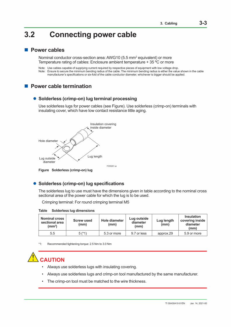
lSolderless (crimp-on) lug terminal processingUse solderless lugs for power cables (see Figure). Use solderless (crimp-on) terminals with insulating cover, which have low contact resistance little aging.
F030201.ai
Insulation covering inside diameter
Hole diameter
Lug outsidediameter
Lug length
Figure Solderless (crimp-on) lug
lSolderless (crimp-on) lug specificationsThe solderless lug to use must have the dimensions given in table according to the nominal cross sectional area of the power cable for which the lug is to be used.
Crimping terminal: For round crimping terminal M5
Table Solderless lug dimensions
Nominal cross sectional area
(mm2) Screw used
(mm) Hole diameter
(mm) Lug outside
diameter (mm)
Lug length (mm)
Insulation covering inside
diameter (mm)
5.5 5 (*1) 5.3 or more 9.7 or less approx.29 5.9 or more
*1: Recommended tightening torque: 2.5 Nm to 3.0 Nm
CAUTION• Always use solderless lugs with insulating covering.
• Always use solderless lugs and crimp-on tool manufactured by the same manufacturer.
• The crimp-on tool must be matched to the wire thickness.
Jan. 14, 2021-00
3. Cabling 3-4
TI 30A30A10-01EN
CAUTION• Power cables must be laid 1 cm or further away from signal cables.
• Power and grounding cable are use power and grounding cables which are in conformance with the safety standard of each country.
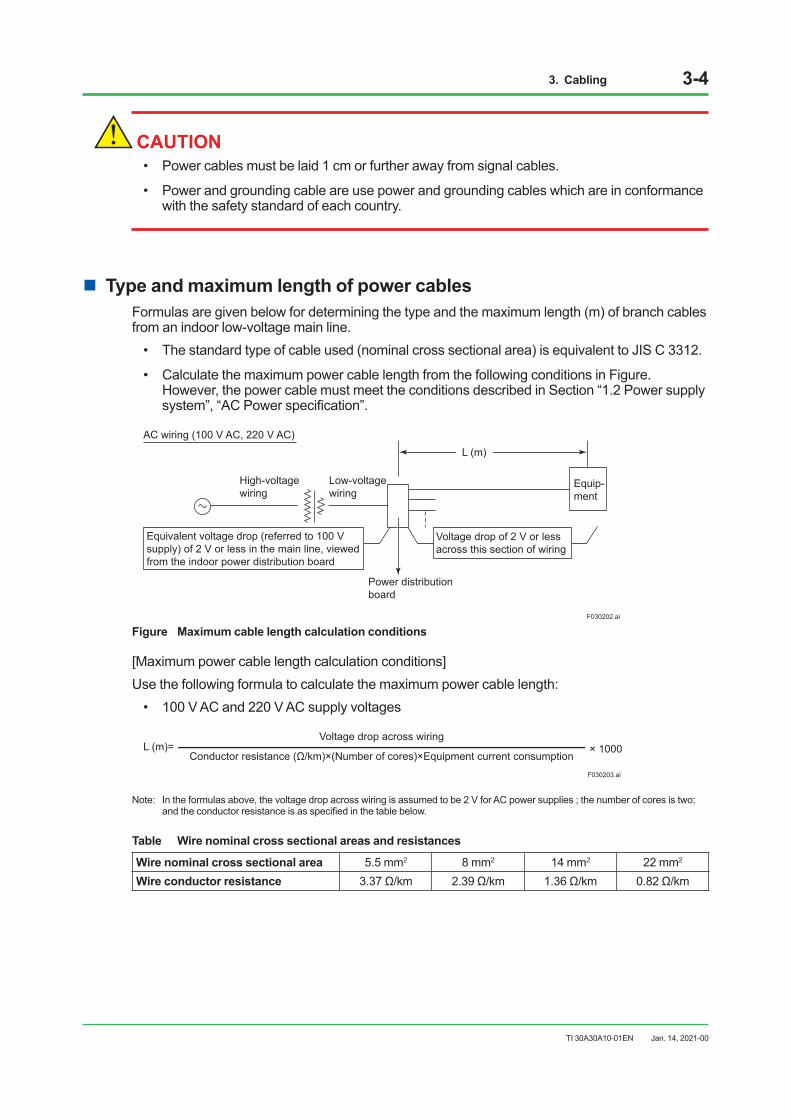
n Type and maximum length of power cablesFormulas are given below for determining the type and the maximum length (m) of branch cables from an indoor low-voltage main line.
• The standard type of cable used (nominal cross sectional area) is equivalent to JIS C 3312.
• Calculate the maximum power cable length from the following conditions in Figure. However, the power cable must meet the conditions described in Section “1.2 Power supply system”, “AC Power specification”.
Low-voltage wiring
Power distribution board
Equivalent voltage drop (referred to 100 V supply) of 2 V or less in the main line, viewed from the indoor power distribution board
Voltage drop of 2 V or less across this section of wiring
Equip- ment
L (m) AC wiring (100 V AC, 220 V AC)
High-voltage wiring
F030202.ai
Figure Maximum cable length calculation conditions
[Maximum power cable length calculation conditions]Use the following formula to calculate the maximum power cable length:
• 100 V AC and 220 V AC supply voltages
F030203.ai
L (m)=Voltage drop across wiring
Conductor resistance (Ω/km)×(Number of cores)×Equipment current consumption× 1000
Note: In the formulas above, the voltage drop across wiring is assumed to be 2 V for AC power supplies ; the number of cores is two; and the conductor resistance is as specified in the table below.
Table Wire nominal cross sectional areas and resistances
Wire nominal cross sectional area 5.5 mm2 8 mm2 14 mm2 22 mm2 Wire conductor resistance 3.37 Ω/km 2.39 Ω/km 1.36 Ω/km 0.82 Ω/km
Jan. 14, 2021-00
3. Cabling 3-5
TI 30A30A10-01EN
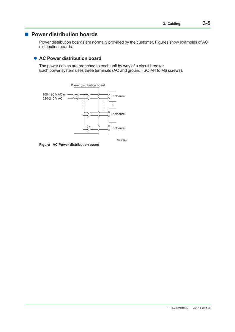
n Power distribution boardsPower distribution boards are normally provided by the customer. Figures show examples of AC distribution boards.
lAC Power distribution boardThe power cables are branched to each unit by way of a circuit breaker. Each power system uses three terminals (AC and ground: ISO M4 to M6 screws).
Enclosure
Enclosure
Enclosure
Power distribution board
100-120 V AC or220-240 V AC
F030204.ai
Figure AC Power distribution board
Jan. 14, 2021-00
3. Cabling 3-6
TI 30A30A10-01EN
3.3 Connecting grounding cable3.3.1 Connecting grounding cable for the enclosure
SEE ALSO See “Section 1.3 Grounding n Grounding of enclosure” for grounding of enclosure.
CAUTIONThe protective conductor terminal of the N-IO field enclosure should be connected to the protective grounding system.
n Grounding cablesNominal conductor cross-section area: AWG6 (14 mm2) or moreTemperature rating of cables: Enclosure ambient temperature + 35 ºC or moreNote: The cable used should be determined according to the standards in each country and region.Note: Ensure to secure the minimum bending radius of the cable. The minimum bending radius is either the value shown in the cable
manufacturer’s specifications or six-fold of the cable conductor diameter, whichever is bigger should be applied.
n Grounding cable terminationUse solderless lugs for power cables.The solderless lug to use must have the dimensions given in table according to the nominal cross sectional area of the cable for which the lug is to be used.
Crimping terminal: For round crimping terminal M10
Table Solderless lug dimensions
Nominal cross sectional area (mm2)
Hole diameter(mm)
22.0 10.3 or more
CAUTION• Always use solderless lugs and crimp-on tool manufactured by the same manufacturer.
• The crimp-on tool must be matched to the wire thickness.
Jan. 14, 2021-00
3. Cabling 3-7
TI 30A30A10-01EN
3.3.2 Connecting grounding cable to grounding bar for shield lines
SEE ALSO See “Section 1.3 Grounding n Grounding of grounding bar for shield lines” for more information.
n Grounding cablesNominal conductor cross-sectional area: 0.5 to 6.0 mm2 (Solid) 0.5 to 4.0 mm2 (Flexible)Temperature rating of cables: Enclosure ambient temperature + 35 ºC or more
n Grounding cable terminationConnect the cable with the cable coating stripped (without a sleeve).The peel-off length should be 16 mm.
Jan. 14, 2021-00
3. Cabling 3-8
TI 30A30A10-01EN
3.4 Connecting signal cable3.4.1 Connecting signal cable (for CENTUM VP)
For CENTUM VP, the A2BN3D terminal block in the N-IO field enclosure interfaces with the field devices.
SEE ALSO For signal cable connection for CENTUM VP, refer to the “CENTUM VP Installation Guidance” (TI 33J01J10-
01EN).
3.4.2 Connecting signal cable (for ProSafe-RS)For ProSafe-RS, the field wiring terminal block in the enclosure interfaces with the field devices.
n Process I/O signal connection• Power, control bus, and signal cables must be separately laid. Avoid laying them in parallel.
• In case of using multicore cables for field wiring, do not share one multicore cable with I/O modules of different voltage types (i.e. 24 V DC).
• Use group-shielded twisted-pair cables specifically for noise countermeasures, as necessary. A twisted-pair cable pitch of 50 mm or less should be used and the shielded cables must be grounded.
• The use of twisted-pair cables is also recommended for digital signals.
• The twisted-pair cable has the following advantages over a solid wire:
- More flexible for easy curving and cabling in limited spaces.
• Signal cables must be clamped so that their weight does not affect terminals.
• Be careful not to apply excessive force to the cable when laying it.
n When mixing AI and DO in the same multi-core cable (N-IO I/O Unit)When mixing analog input (AI) signal and digital output (DO) signal in the same multi-core cable, take the following influence from DO pulse diagnostics or ON/OFF operation into consideration.
• The accuracy for Analog input function may be worse by several tens of μA depending on the type, length of a cable and DO load current.
• A delay may occur in updating the HART event.
lSpring clamp terminal, Push-in terminal
CAUTION• The N-IO field enclosure for ProSafe-RS uses a spring clamp terminal and push-in terminal
for signal connection.
• For cable connection with a sleeve attached, use a sleeve and a clamp tool from the same manufacturer.
• Use a clamp tool which suits the cable thickness.
Jan. 14, 2021-00
3. Cabling 3-9
TI 30A30A10-01EN
n Signal cablesNominal conductor cross-sectional area: 0.5 to 2.5 mm2 (AWG 20 to 14)Temperature rating of cables: Enclosure ambient temperature + 35 ºC or moreNote: Ensure to secure the minimum bending radius of the cable. The minimum bending radius is either the value shown in the cable
manufacturer’s specifications or six-fold of the cable conductor diameter, whichever is bigger should be applied.
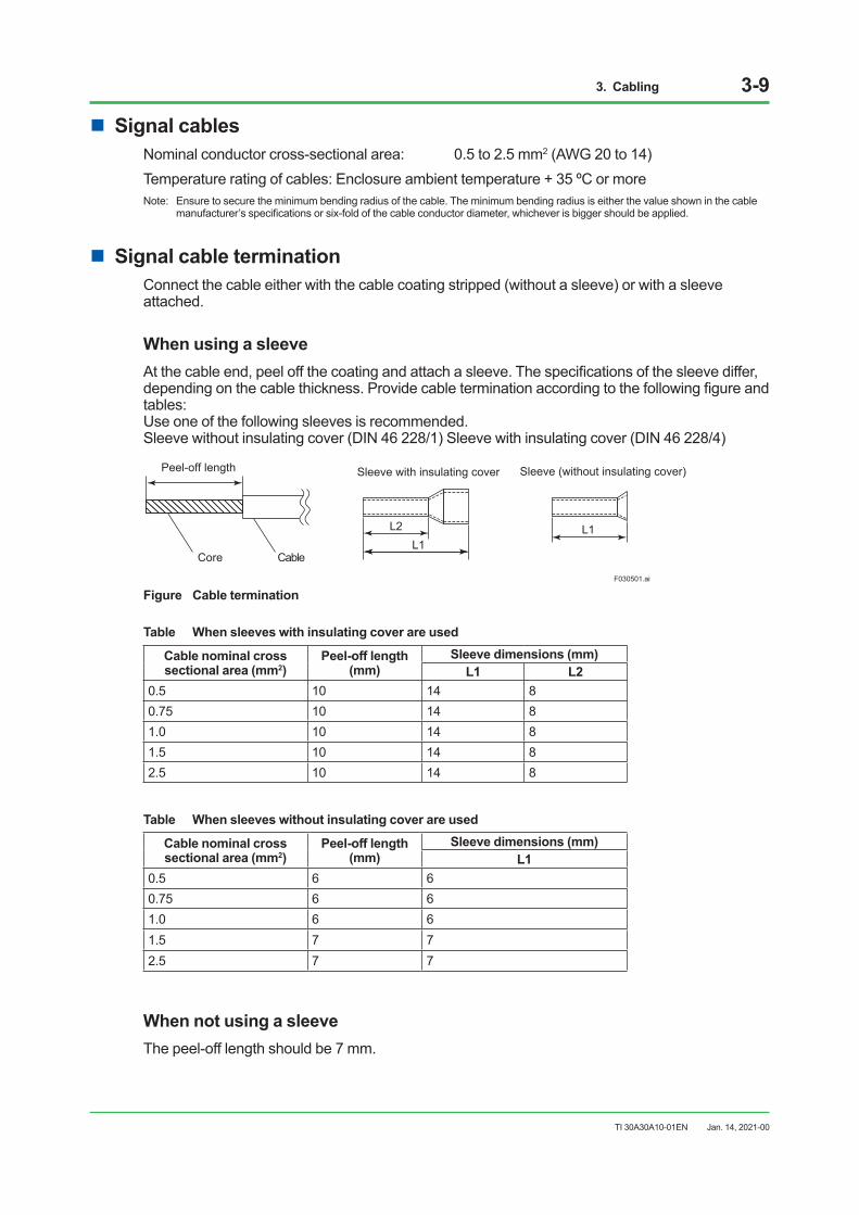
n Signal cable terminationConnect the cable either with the cable coating stripped (without a sleeve) or with a sleeve attached.
When using a sleeveAt the cable end, peel off the coating and attach a sleeve. The specifications of the sleeve differ, depending on the cable thickness. Provide cable termination according to the following figure and tables: Use one of the following sleeves is recommended. Sleeve without insulating cover (DIN 46 228/1) Sleeve with insulating cover (DIN 46 228/4)
L1L2 L1
Sleeve with insulating cover
Core Cable
Peel-off length
F030501.ai
Sleeve (without insulating cover)
Figure Cable termination
Table When sleeves with insulating cover are used
Cable nominal cross sectional area (mm2)
Peel-off length(mm)
Sleeve dimensions (mm)L1 L2
0.5 10 14 80.75 10 14 81.0 10 14 81.5 10 14 82.5 10 14 8
Table When sleeves without insulating cover are used
Cable nominal cross sectional area (mm2)
Peel-off length(mm)
Sleeve dimensions (mm)L1
0.5 6 60.75 6 61.0 6 61.5 7 72.5 7 7
When not using a sleeveThe peel-off length should be 7 mm.
Jan. 14, 2021-00
3. Cabling 3-10
TI 30A30A10-01EN
3.4.3 Connecting shield lines of the signal cableFor a signal cable with a shield line, connect the shield line to the grounding bar for a shield line in the enclosure.
n Shield linesNominal conductor cross-sectional area: 0.5 to 6.0 mm2 (Solid) 0.5 to 4.0 mm2 (Flexible)Temperature rating of cables: Enclosure ambient temperature + 35 ºC or more
n Shield lines terminationConnect the cable with the cable coating stripped (without a sleeve). The peel-off length should be 16 mm.
Jan. 14, 2021-00
3. Cabling 3-11
TI 30A30A10-01EN
3.5 Connecting communication cable
n Communication cables
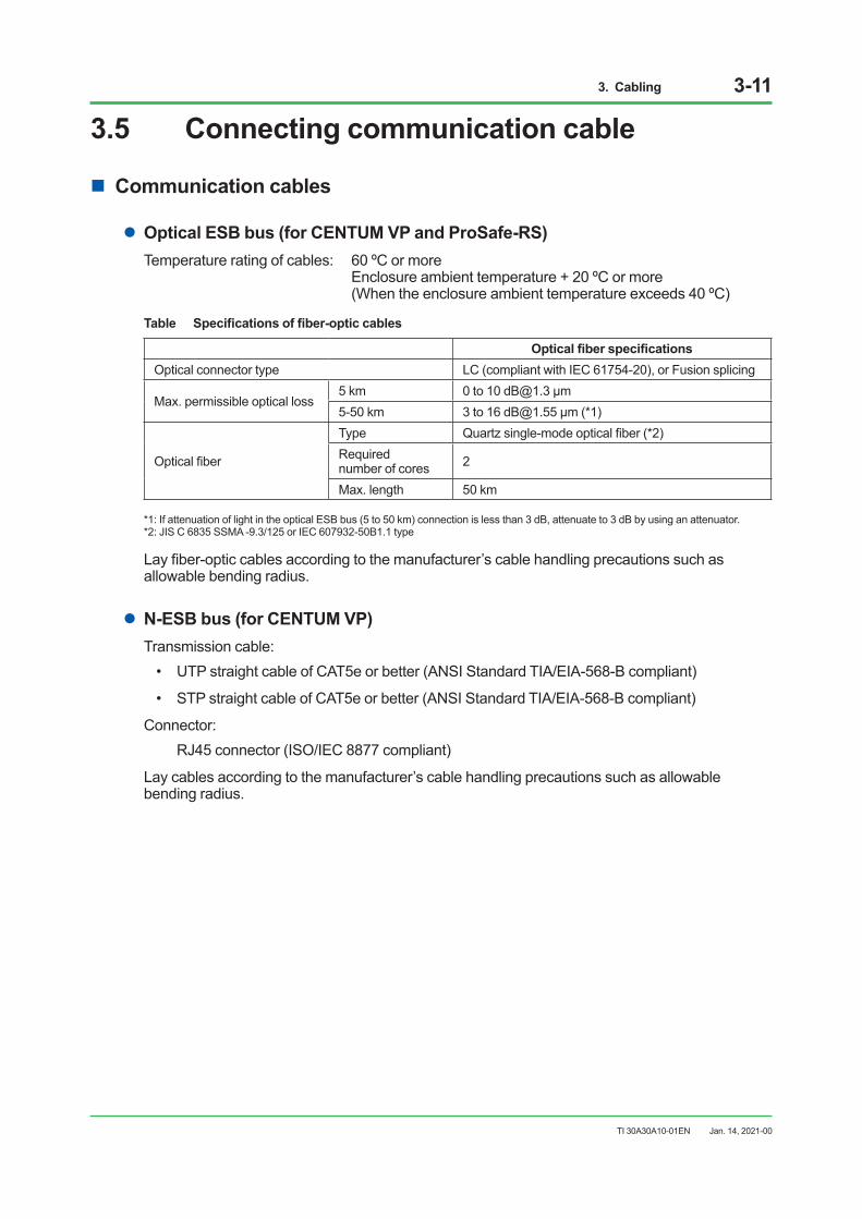
lOptical ESB bus (for CENTUM VP and ProSafe-RS)Temperature rating of cables: 60 ºC or more Enclosure ambient temperature + 20 ºC or more (When the enclosure ambient temperature exceeds 40 ºC)
Table Specifications of fiber-optic cables
Optical fiber specificationsOptical connector type LC (compliant with IEC 61754-20), or Fusion splicing
Max. permissible optical loss5 km 0 to 10 [email protected] μm5-50 km 3 to 16 [email protected] μm (*1)
Optical fiber
Type Quartz single-mode optical fiber (*2)Requirednumber of cores 2
Max. length 50 km
*1: If attenuation of light in the optical ESB bus (5 to 50 km) connection is less than 3 dB, attenuate to 3 dB by using an attenuator.*2: JIS C 6835 SSMA -9.3/125 or IEC 607932-50B1.1 type
Lay fiber-optic cables according to the manufacturer’s cable handling precautions such as allowable bending radius.
lN-ESB bus (for CENTUM VP)Transmission cable:
• UTP straight cable of CAT5e or better (ANSI Standard TIA/EIA-568-B compliant)
• STP straight cable of CAT5e or better (ANSI Standard TIA/EIA-568-B compliant)
Connector: RJ45 connector (ISO/IEC 8877 compliant)
Lay cables according to the manufacturer’s cable handling precautions such as allowable bending radius.
Jan. 14, 2021-00
4.Installationspecifications 4-1
TI 30A30A10-01EN
4. Installation specificationsThis section summarizes power consumption, in-rush current, circuit protector ratings, parts durability and other data for the installation.
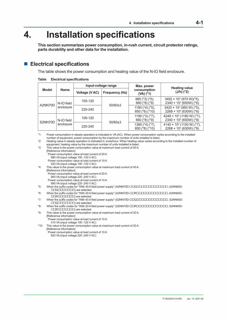
n Electrical specificationsThe table shows the power consumption and heating value of the N-IO field enclosure.
Table Electrical specifications
Model NameInput-voltage range Max. power
consumption(VA) (*1)
Heating value(J/h) (*2)Voltage (V AC) Frequency (Hz)
A2NN70D N-IO field enclosure
100-120 50/60±3
980 (*3) (*5),660 (*6) (*9)
3492 × 103 (970 W)(*5), 2340 × 103 (650W) (*6)
220-240 1180 (*4) (*5),850 (*6) (*10)
3420 × 103 (950 W) (*5), 2268 × 103 (630W) (*6)
S2NN70D N-IO field enclosure
100-120 50/60±3
1190 (*3) (*7),660 (*8) (*9)
4248 × 103 (1180 W) (*7), 2340 × 103 (650W) (*8)
220-240 1360 (*4) (*7), 850 (*8) (*10)
4140 × 103 (1150 W) (*7), 2268 × 103 (630W) (*8)
*1: Power consumption in steady operation is indicated in VA (AC). When power consumption varies according to the installed number of equipment, power consumption by the maximum number of units installed is listed.
*2: Heating value in steady operation is indicated in Joule/hour. When heating value varies according to the installed number of equipment, heating value by the maximum number of units installed is listed.
*3: This value is the power consumption value at maximum load current of 40 A. [Reference information] Power consumption value at load current of 20 A 680 VA (input voltage 100 -120 V AC) Power consumption value at load current of 10 A 420 VA (input voltage 100 -120 V AC)*4: This value is the power consumption value at maximum load current of 40 A. [Reference information] Power consumption value at load current of 20 A 900 VA (input voltage 220 -240 V AC) Power consumption value at load current of 10 A 690 VA (input voltage 220 -240 V AC)*5: When the suffix codes for "With 40 A field power supply" (A2NN70D-Q, A2NN60D-
Q) are selected.*6: When the suffix codes for "With 20 A field power supply" (A2NN70D-R, A2NN60D-
R) are selected. *7: When the suffix codes for "With 40 A field power supply" (S2NN70D-Q, S2NN60D-
Q) are selected.*8: When the suffix codes for "With 20 A field power supply" (S2NN70D-R, S2NN60D-
R) are selected. *9: This value is the power consumption value at maximum load current of 20 A. [Reference information] Power consumption value at load current of 10 A 410 VA (input voltage 100 -120 V AC)*10: This value is the power consumption value at maximum load current of 20 A. [Reference information] Power consumption value at load current of 10 A 620 VA (input voltage 220 -240 V AC)
Jan. 14, 2021-00
4.Installationspecifications 4-2
TI 30A30A10-01EN
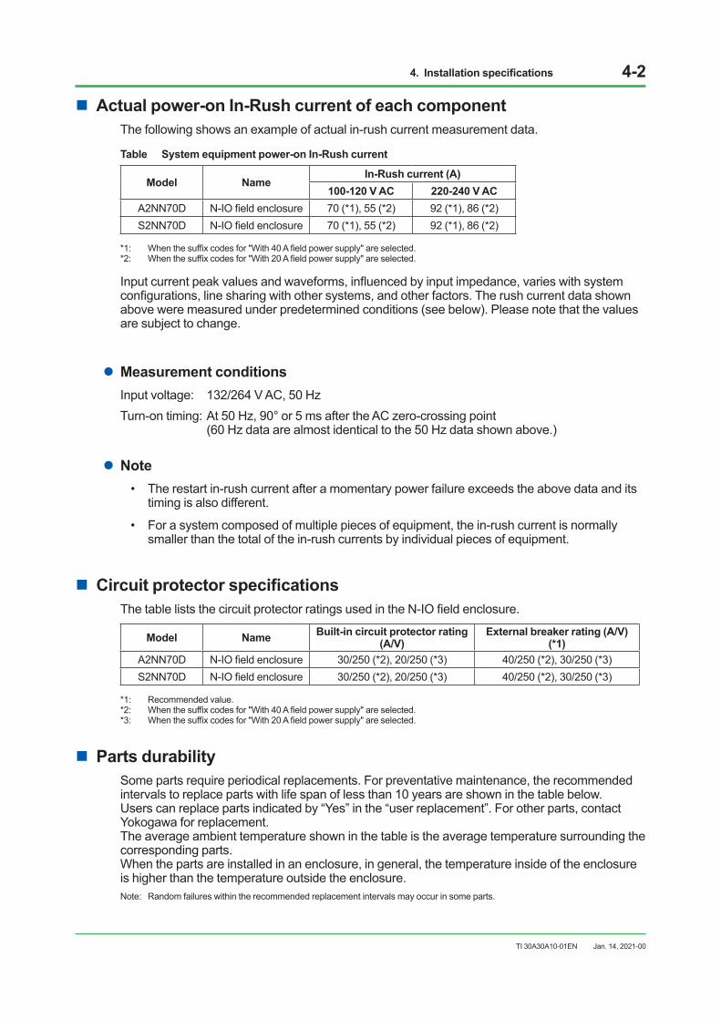
n Actual power-on In-Rush current of each componentThe following shows an example of actual in-rush current measurement data.
Table System equipment power-on In-Rush current
Model NameIn-Rush current (A)
100-120 V AC 220-240 V ACA2NN70D N-IO field enclosure 70 (*1), 55 (*2) 92 (*1), 86 (*2)S2NN70D N-IO field enclosure 70 (*1), 55 (*2) 92 (*1), 86 (*2)
*1: When the suffix codes for "With 40 A field power supply" are selected.*2: When the suffix codes for "With 20 A field power supply" are selected.
Input current peak values and waveforms, influenced by input impedance, varies with system configurations, line sharing with other systems, and other factors. The rush current data shown above were measured under predetermined conditions (see below). Please note that the values are subject to change.
lMeasurement conditionsInput voltage: 132/264 V AC, 50 HzTurn-on timing: At 50 Hz, 90° or 5 ms after the AC zero-crossing point (60 Hz data are almost identical to the 50 Hz data shown above.)
lNote• The restart in-rush current after a momentary power failure exceeds the above data and its
timing is also different.
• For a system composed of multiple pieces of equipment, the in-rush current is normally smaller than the total of the in-rush currents by individual pieces of equipment.
n Circuit protector specificationsThe table lists the circuit protector ratings used in the N-IO field enclosure.
Model Name Built-in circuit protector rating(A/V)
External breaker rating (A/V) (*1)
A2NN70D N-IO field enclosure 30/250 (*2), 20/250 (*3) 40/250 (*2), 30/250 (*3)S2NN70D N-IO field enclosure 30/250 (*2), 20/250 (*3) 40/250 (*2), 30/250 (*3)
*1: Recommended value.*2: When the suffix codes for "With 40 A field power supply" are selected.*3: When the suffix codes for "With 20 A field power supply" are selected.
n Parts durabilitySome parts require periodical replacements. For preventative maintenance, the recommended intervals to replace parts with life span of less than 10 years are shown in the table below. Users can replace parts indicated by “Yes” in the “user replacement”. For other parts, contact Yokogawa for replacement. The average ambient temperature shown in the table is the average temperature surrounding the corresponding parts. When the parts are installed in an enclosure, in general, the temperature inside of the enclosure is higher than the temperature outside the enclosure.Note: Random failures within the recommended replacement intervals may occur in some parts.
Jan. 14, 2021-00
4.Installationspecifications 4-3
TI 30A30A10-01EN
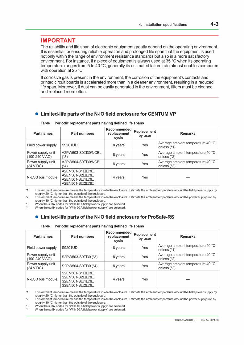
IMPORTANTThe reliability and life span of electronic equipment greatly depend on the operating environment. It is essential for ensuring reliable operation and prolonged life span that the equipment is used not only within the range of environment resistance standards but also in a more satisfactory environment. For instance, if a piece of equipment is always used at 35 °C when its operating temperature ranges from 5 to 40 °C, generally its estimated failure rate almost doubles compared with operation at 25 °C.If corrosive gas is present in the environment, the corrosion of the equipment’s contacts and printed circuit boards is accelerated more than in a cleaner environment, resulting in a reduced life span. Moreover, if dust can be easily generated in the environment, filters must be cleaned and replaced more often.
lLimited-life parts of the N-IO field enclosure for CENTUM VPTable Periodic replacement parts having defined life spans
Part names Part numbers Recommended
replacement cycle
Replacement by user Remarks
Field power supply S9201UD 8 years Yes Average ambient temperature 40 °C or less (*1)
Power supply unit (100-240 V AC)
A2PW503-S030/NCBL (*3) 8 years Yes Average ambient temperature 40 °C
or less (*2)Power supply unit (24 V DC)
A2PW504-S030/NCBL (*4) 8 years Yes Average ambient temperature 40 °C
or less (*2)
N-ESB bus moduleA2EN501-S13A2EN501-S23A2EN501-S13A2EN501-S23
4 years Yes —
*1: This ambient temperature means the temperature inside the enclosure. Estimate the ambient temperature around the field power supply by roughly 20 °C higher than the outside of the enclosure.
*2: This ambient temperature means the temperature inside the enclosure. Estimate the ambient temperature around the power supply unit by roughly 10 °C higher than the outside of the enclosure.
*3: When the suffix codes for "With 40 A field power supply" are selected.*4: When the suffix codes for "With 20 A field power supply" are selected.
lLimited-life parts of the N-IO field enclosure for ProSafe-RSTable Periodic replacement parts having defined life spans
Part names Part numbers Recommended
replacement cycle
Replacement by user Remarks
Field power supply S9201UD 8 years Yes Average ambient temperature 40 °C or less (*1)
Power supply unit (100-240 V AC) S2PW503-S030 (*3) 8 years Yes Average ambient temperature 40 °C
or less (*2)Power supply unit (24 V DC) S2PW504-S030 (*4) 8 years Yes Average ambient temperature 40 °C
or less (*2)
N-ESB bus moduleS2EN501-S13S2EN501-S23S2EN501-S13S2EN501-S23
4 years Yes —
*1: This ambient temperature means the temperature inside the enclosure. Estimate the ambient temperature around the field power supply by roughly 20 °C higher than the outside of the enclosure.
*2: This ambient temperature means the temperature inside the enclosure. Estimate the ambient temperature around the power supply unit by roughly 10 °C higher than the outside of the enclosure.
*3: When the suffix codes for "With 40 A field power supply" are selected.*4: When the suffix codes for "With 20 A field power supply" are selected.
Jan. 14, 2021-00
5. Post-installation inspection and environmental preservation 5-1
TI 30A30A10-01EN
5. Post-installation inspection and environmental preservation
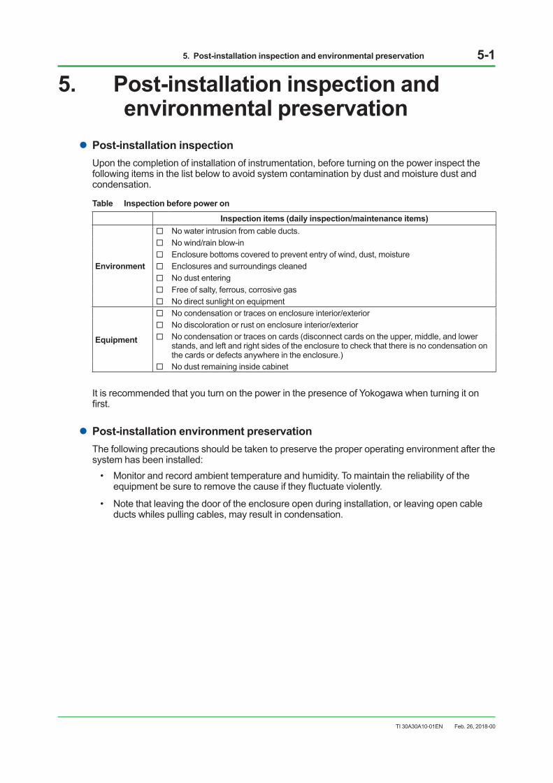
lPost-installation inspectionUpon the completion of installation of instrumentation, before turning on the power inspect the following items in the list below to avoid system contamination by dust and moisture dust and condensation.
Table Inspection before power on
Inspection items (daily inspection/maintenance items)
Environment
No water intrusion from cable ducts. No wind/rain blow-in Enclosure bottoms covered to prevent entry of wind, dust, moisture Enclosures and surroundings cleaned No dust entering Free of salty, ferrous, corrosive gas No direct sunlight on equipment
Equipment
No condensation or traces on enclosure interior/exterior No discoloration or rust on enclosure interior/exterior No condensation or traces on cards (disconnect cards on the upper, middle, and lower
stands, and left and right sides of the enclosure to check that there is no condensation on the cards or defects anywhere in the enclosure.)
No dust remaining inside cabinet
It is recommended that you turn on the power in the presence of Yokogawa when turning it on first.
lPost-installation environment preservationThe following precautions should be taken to preserve the proper operating environment after the system has been installed:
• Monitor and record ambient temperature and humidity. To maintain the reliability of the equipment be sure to remove the cause if they fluctuate violently.
• Note that leaving the door of the enclosure open during installation, or leaving open cable ducts whiles pulling cables, may result in condensation.
Feb. 26, 2018-00
i
TI 30A30A10-01EN
Revision Informationl Title : Installation Guidance for N-IO field enclosurel Manual No. : TI 30A30A10-01EN
May 2021 /6th Edition1.1 Installation Environment n Installation Specification [The voltage of Category 1 and 2 was changed.]
Jan. 2021 /5th EditionIntroduction was changed.1.3 Grounding [Description was revised. Correction of errors.]1.5 Cabling requirements [Suffix codes ware added.]1.6 The compliance with marine standards was added.2.2 Unpacking [Description was added.]3. Cabling [Suffix codes ware added.]4. Installation specifications [Note was added. Suffix codes ware added.]
Mar. 2020 /4th EditionIntroduction Updated descriptions of trademark.1.1 Installation environment n Measurement categories [Table was revised.]1.4.1 Noise sources and noise countermeasures n Examples of spark-killer and diode installation [Remark (*1) and (*2) were added.]2.1 Precautions for transportation l Carrying space, passage [Remark (*1) was added.]3.4.2 Connecting signal cable (for ProSafe-RS) n Signal cable termination [Table for sleeves was revised.]
Jan. 2019 /3rd Edition1.1 Installation environment [Contact information was changed]1.4.2 Countermeasures against Static Electricity [Arrangement Information of wrist straps and conductive sheets were deleted]2.2 Unpacking Caution [Contact information for Condensation was deleted] Caution [Contact information at product fall was changed]2.3 Storage [Contact information was changed]4. Installation specifications n Circuit protector specifications [Note was added] May 2018 /2nd Edition1.1 Installation environment n Applied standards [Document number of TI “Explosion Protection” was added.] n Installation environment specifications [Correction of clerical errors of insulation resistance
specification.]1.4.1 Noise sources and noise countermeasures n Examples of spark-killer installation [Title was revised.]2.3 Storage n Storage of unpacked equipment [Description about storage was added.]4. Installation specifications n Electrical specifications [Remark (*3) and (*4) about power consumption was added.]
Feb. 2018/1st EditionNewly published
May 3, 2021-00

Written by Yokogawa Electric Corporation
Published by Yokogawa Electric Corporation 2-9-32 Nakacho, Musashino-shi, Tokyo 180-8750, JAPAN
Subject to change without notice.


![PROFINET IO bus interface, PROFINET IO [BU 2400] · NORD GmbH & Co. KG in a field bus system. It is intended for all qualified electricians who plan, install and set up the field](https://img.pdfslide.us/doc/110x75/60558c7034bbf56598483002/profinet-io-bus-interface-profinet-io-bu-2400-nord-gmbh-co-kg-in-a-field.jpg)