Embed Size (px)
Citation preview
SMA
SMA
SUNNY BOY
NSM-GG10-TI-en-10 | Version 1.0ENGLISH
Technical InformationSMA GRID GUARD 10.0Grid Management Services through SMA Inverters
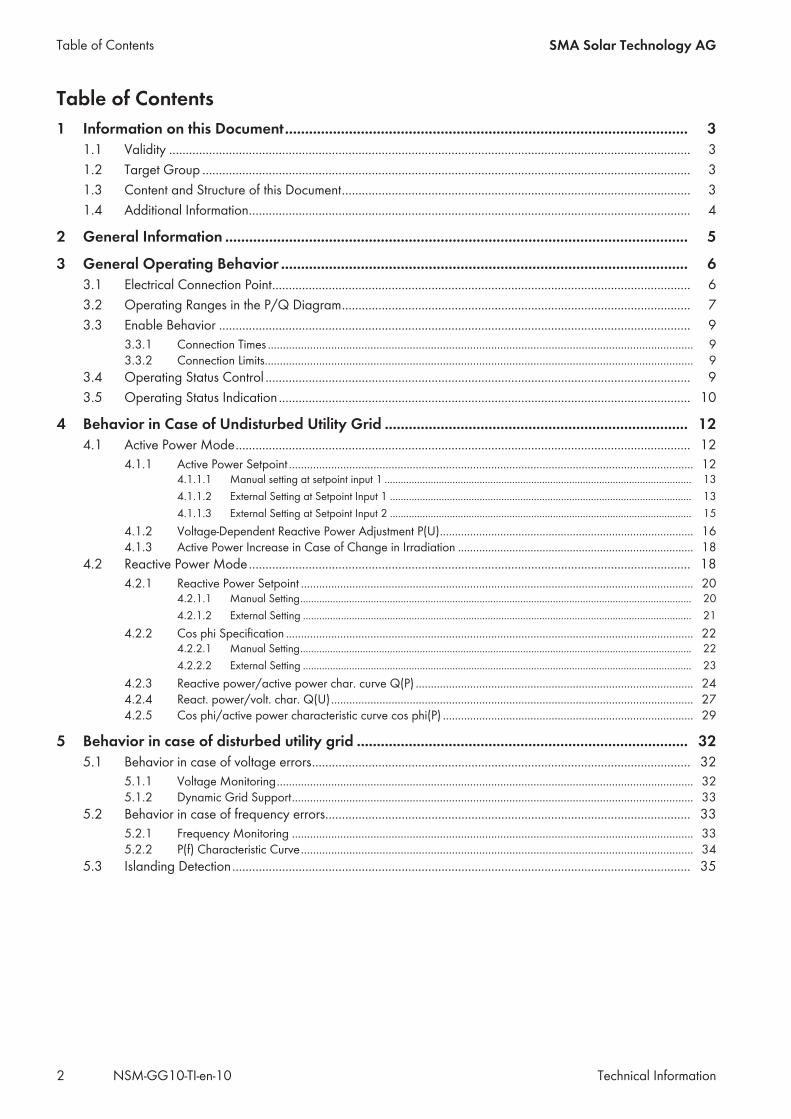
Table of Contents SMA Solar Technology AG
Technical InformationNSM-GG10-TI-en-102
Table of Contents1 Information on this Document..................................................................................................... 3
1.1 Validity ............................................................................................................................................................. 31.2 Target Group ................................................................................................................................................... 31.3 Content and Structure of this Document......................................................................................................... 31.4 Additional Information..................................................................................................................................... 4
2 General Information .................................................................................................................... 5
3 General Operating Behavior ...................................................................................................... 63.1 Electrical Connection Point.............................................................................................................................. 63.2 Operating Ranges in the P/Q Diagram......................................................................................................... 73.3 Enable Behavior .............................................................................................................................................. 9
3.3.1 Connection Times ............................................................................................................................................. 93.3.2 Connection Limits.............................................................................................................................................. 9
3.4 Operating Status Control ................................................................................................................................ 93.5 Operating Status Indication ............................................................................................................................ 10
4 Behavior in Case of Undisturbed Utility Grid ............................................................................ 124.1 Active Power Mode......................................................................................................................................... 12
4.1.1 Active Power Setpoint ...................................................................................................................................... 124.1.1.1 Manual setting at setpoint input 1 ................................................................................................................. 134.1.1.2 External Setting at Setpoint Input 1 ............................................................................................................... 134.1.1.3 External Setting at Setpoint Input 2 ............................................................................................................... 15
4.1.2 Voltage-Dependent Reactive Power Adjustment P(U).................................................................................... 164.1.3 Active Power Increase in Case of Change in Irradiation .............................................................................. 18
4.2 Reactive Power Mode..................................................................................................................................... 184.2.1 Reactive Power Setpoint .................................................................................................................................. 20
4.2.1.1 Manual Setting................................................................................................................................................ 204.2.1.2 External Setting ............................................................................................................................................... 21
4.2.2 Cos phi Specification ....................................................................................................................................... 224.2.2.1 Manual Setting................................................................................................................................................ 224.2.2.2 External Setting ............................................................................................................................................... 23
4.2.3 Reactive power/active power char. curve Q(P) ............................................................................................ 244.2.4 React. power/volt. char. Q(U)........................................................................................................................ 274.2.5 Cos phi/active power characteristic curve cos phi(P) ................................................................................... 29
5 Behavior in case of disturbed utility grid ................................................................................... 325.1 Behavior in case of voltage errors.................................................................................................................. 32
5.1.1 Voltage Monitoring.......................................................................................................................................... 325.1.2 Dynamic Grid Support..................................................................................................................................... 33
5.2 Behavior in case of frequency errors.............................................................................................................. 335.2.1 Frequency Monitoring ..................................................................................................................................... 335.2.2 P(f) Characteristic Curve.................................................................................................................................. 34
5.3 Islanding Detection.......................................................................................................................................... 35
1 Information on this DocumentSMA Solar Technology AG
Technical Information 3NSM-GG10-TI-en-10
1 Information on this Document1.1 ValidityThis document is valid for:
• SMA inverters that comply with European Grid Connection Regulations through SMA Grid Guard 10.0according to Regulation (EU) 2016/631 for Establishing a Network Code on Requirements for Connection ofGenerators (also known as Requirements for Generators (RfG))
1.2 Target GroupThe functions described in this document are to be configured by qualified persons only. Qualified persons must havethe following skills:
• Detailed knowledge of the grid management services• Knowledge of how an inverter works and is operated• Knowledge of how the product works and is operated• Training in the installation and commissioning of electrical devices and installations• Knowledge of all applicable laws, standards and directives
1.3 Content and Structure of this DocumentIn this document the grid management service functions of the inverters are described and the object names of theparameters are stated that can be used to set the functions.
Abbreviations usedFrequently used abbreviations are listed and described in the following:
Designation in the docu-ment
Complete designation Explanation
W Watt Contained in object names of active power parameters
VAr Volt-ampere reactive Contained in object names of reactive power parameters
Pu Per unit Contained in object names of parameters that refer to an-other size (e.g. to the grid nominal voltage).
Ena Enable Contained in object names of activation/deactivation pa-rameters
Mod Mode Contained in object names for which a setting can be se-lected from a list.
Q1 Quadrant 1 1st quadrant of the P/Q diagram
Q2 Quadrant 2 2nd quadrant of the P/Q diagram
Q3 Quadrant 3 3rd quadrant of the P/Q diagram
Q4 Quadrant 4 4th quadrant of the P/Q diagram
Rtg Rating Contained in object names of rating parameters
Stt State Contained in object names of state parameters
PF Power factor Contained in object names of cos phi parameters
1 Information on this Document SMA Solar Technology AG
Technical InformationNSM-GG10-TI-en-104
1.4 Additional InformationFor more information, please go to www.SMA-Solar.com.
Title and information content Type of information
"Application for SMA Grid Guard Code" Form
"PUBLIC CYBER SECURITY - Guidelines for a Secure PV System Communication" Technical information
"Parameters and Measured Values"Overview of all inverter operating parameters and their configuration options
Technical Information
"SMA and SunSpec Modbus® Interface"Information on the Modbus interface
Technical Information
"Modbus® parameters and measured values"Device-specific register HTML file
Technical Information
2 General InformationSMA Solar Technology AG
Technical Information 5NSM-GG10-TI-en-10
2 General Information
Country data sets and parameter settingsThe inverters are equipped with various country data sets that contain useful settings for the functions described in thisdocument in order to comply with local standards and directives. After commissioning, the country data set must be seteither on the user interface of the inverter via the installation assistant or via the higher-level control unit (e.g.SMA Data Manager or Modbus control).The parameters for setting the functions described in this document can either be set via the user interface of theinverter or via a higher-level control unit. An overview of all parameter settings of the inverter can be exported via theuser interface of the inverter or, in the case of systems with SMA Data Manager, via the user interface of theSMA Data Manager. If a Sunny Portal system is present, the parameter settings can also be exported via theSunny Portal
Communication protocols
SMA Data/RS485All parameters of the inverter are listed in the product-specific parameter list. The object name can be used todetermine the parameter name for SMA Data/RS485 as well as the path via which the parameter can be reached.You can also find additional information in the list (e.g. setting range, setting values, default value). The product-specific parameter list can be found in the download area at www.SMA-Solar.com. The list is assigned to thedocument type "Technical Information".
SMA ModbusThe product-specific Modbus list contains all parameters of the inverter with associated SMA Modbus register address.The object name can be used to determine the register address for SMA Modbus. You can also find additionalinformation in the list (e.g. format, type, access). The product-specific Modbus list can be found in the download areaat www.SMA-Solar.com. The list is assigned to the document type "Technical Information".
SunSpec ModbusThe product-specific Modbus list contains all parameters of the inverter with associated SunSpec Modbus registeraddress. The object name can be used to determine the register address for SunSpec Modbus. You can also findadditional information in the list (e.g. information model, access, scaling factor). The product-specific Modbus list canbe found in the download area at www.SMA-Solar.com. The list is assigned to the document type "TechnicalInformation".
SMA Grid Guard protectionAll grid-relevant parameters for PV inverters are provided with SMA Grid Guard protection after the first ten feed-inhours have elapsed, and for battery inverters after the first ten operating hours have elapsed. When SMA Grid Guardprotection is active, it is necessary to enter the SMA Grid Guard code in order to change grid-relevant parameters. Theorder form for the SMA Grid Guard code is available in the download area at www.SMA-Solar.com.In the "Grid Guard" column of the product-specific parameter and Modbus list you can see which parameters areprovided with the Grid Guard protection. The product-specific parameter and Modbus list is available in the downloadarea at www.SMA-Solar.com.
3 General Operating Behavior SMA Solar Technology AG
Technical InformationNSM-GG10-TI-en-106
3 General Operating Behavior3.1 Electrical Connection Point
SMA ENERGY METER
SUNNY PORTALpowered by ennexOS
SM
A E
NER
GY
SY
STE
M
SMA DATAMANAGER
M2
M1
CUSTOMER SYSTEM
UTILITYGRID
SMA PV SYSTEM
Alternating current
Solar energy
Communication
LOA
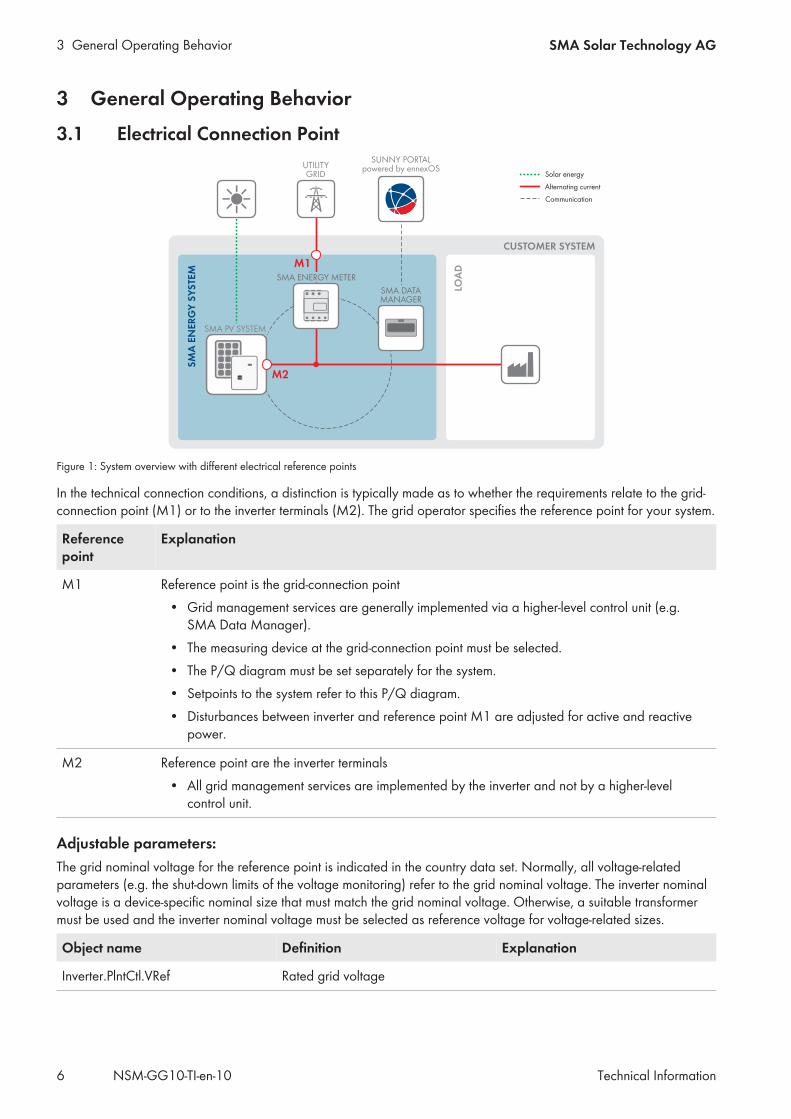
DFigure 1: System overview with different electrical reference points
In the technical connection conditions, a distinction is typically made as to whether the requirements relate to the grid-connection point (M1) or to the inverter terminals (M2). The grid operator specifies the reference point for your system.
Referencepoint
Explanation
M1 Reference point is the grid-connection point• Grid management services are generally implemented via a higher-level control unit (e.g.
SMA Data Manager).• The measuring device at the grid-connection point must be selected.• The P/Q diagram must be set separately for the system.• Setpoints to the system refer to this P/Q diagram.• Disturbances between inverter and reference point M1 are adjusted for active and reactive
power.
M2 Reference point are the inverter terminals• All grid management services are implemented by the inverter and not by a higher-level
control unit.
Adjustable parameters:The grid nominal voltage for the reference point is indicated in the country data set. Normally, all voltage-relatedparameters (e.g. the shut-down limits of the voltage monitoring) refer to the grid nominal voltage. The inverter nominalvoltage is a device-specific nominal size that must match the grid nominal voltage. Otherwise, a suitable transformermust be used and the inverter nominal voltage must be selected as reference voltage for voltage-related sizes.
Object name Definition Explanation
Inverter.PlntCtl.VRef Rated grid voltage
3 General Operating BehaviorSMA Solar Technology AG
Technical Information 7NSM-GG10-TI-en-10
Object name Definition Explanation
Inverter.VRtg Inverter nominal voltage Non-adjustable nominal size. Indi-cated as phase voltage for single-phase inverters, otherwise as outerconductor voltage.
Inverter.VRefIntMod Reference voltage selection Specifies whether the grid nominalvoltage or the inverter nominal volt-age is used as reference voltage forvoltage-related sizes.
Inverter.PlntCtl.AppVol Applicable voltages Specifies whether the phase voltage,outer conductor voltage or both volt-ages are to be used for dynamic gridsupport and voltage monitoring.
Inverter.PlntCtl.VRefMod Phase reference of grid nominal volt-age
Outer conductor / phase voltage
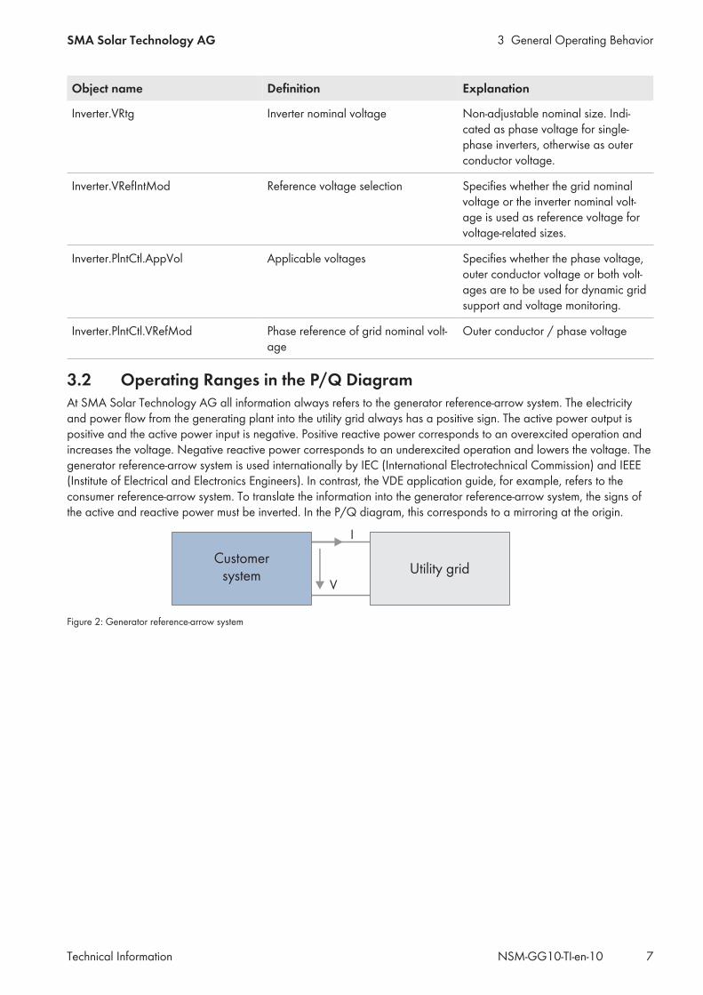
3.2 Operating Ranges in the P/Q DiagramAt SMA Solar Technology AG all information always refers to the generator reference-arrow system. The electricityand power flow from the generating plant into the utility grid always has a positive sign. The active power output ispositive and the active power input is negative. Positive reactive power corresponds to an overexcited operation andincreases the voltage. Negative reactive power corresponds to an underexcited operation and lowers the voltage. Thegenerator reference-arrow system is used internationally by IEC (International Electrotechnical Commission) and IEEE(Institute of Electrical and Electronics Engineers). In contrast, the VDE application guide, for example, refers to theconsumer reference-arrow system. To translate the information into the generator reference-arrow system, the signs ofthe active and reactive power must be inverted. In the P/Q diagram, this corresponds to a mirroring at the origin.
I
Customersystem Utility grid
V
Figure 2: Generator reference-arrow system
3 General Operating Behavior SMA Solar Technology AG
Technical InformationNSM-GG10-TI-en-108
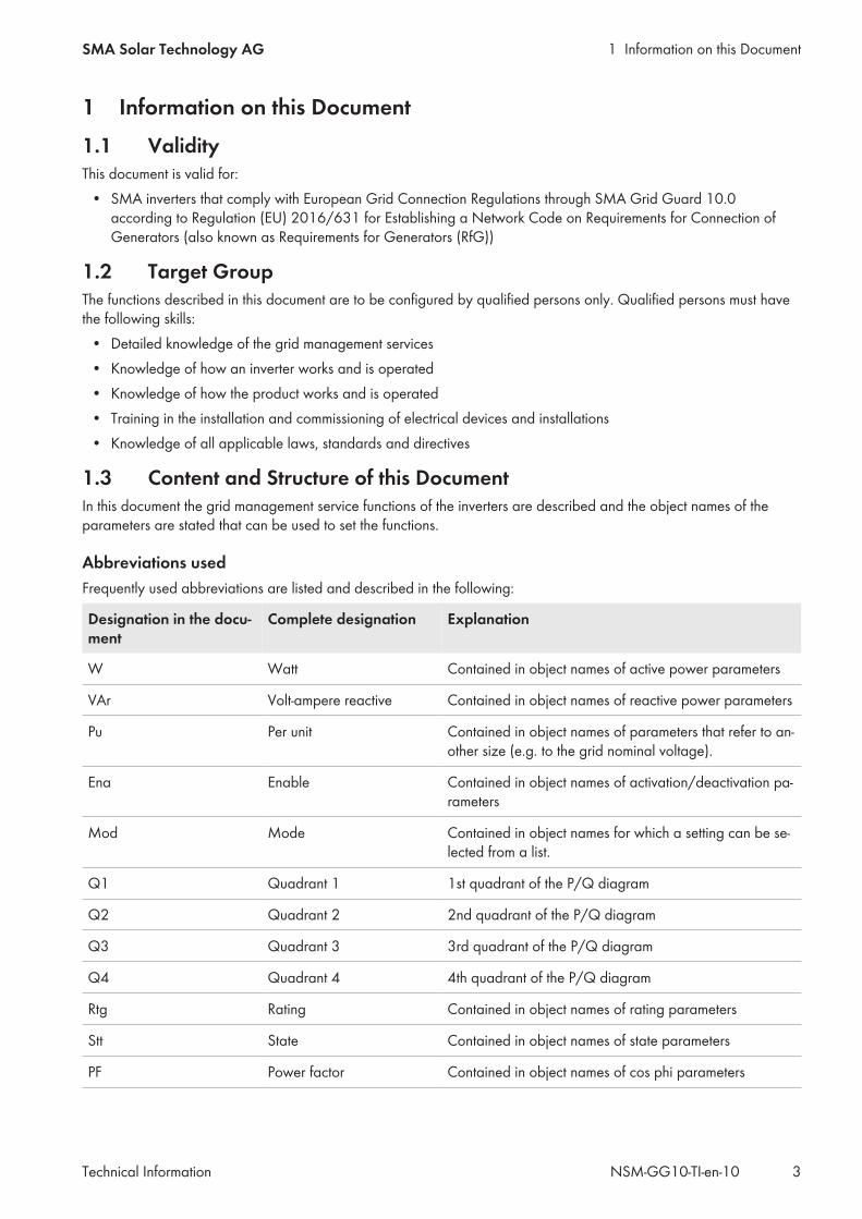
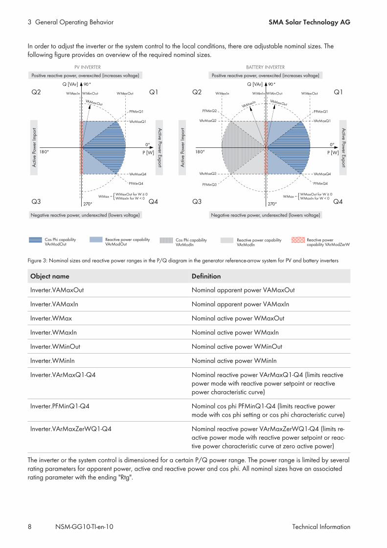
In order to adjust the inverter or the system control to the local conditions, there are adjustable nominal sizes. Thefollowing figure provides an overview of the required nominal sizes.
P [W]
Q [VAr]
180°
0°
90°
270°Q3 Q4
Q2 Q1
VArMaxQ1
VArMaxQ4
WMinIn WMinOut
VAMaxOut
WMaxOut
VAMaxIn
PFMinQ1
PFMinQ4
WMaxIn
VArMaxQ2
VArMaxQ3
PFMinQ3
PFMinQ2
P [W]
Q [VAr]
180°
0°
90°
270°Q3 Q4
Q2 Q1
VArMaxQ1
VArMaxQ4
WMinOut
VAMaxOut
WMaxOut
PFMinQ1
PFMinQ4
WMaxIn
WMaxIn for W < 0WMaxOut for W ≥ 0
WMax = { WMaxIn for W < 0WMaxOut for W ≥ 0
WMax = {
Act
ive
Pow
er Im
po
rt Active Pow
er Expo
rt
Positive reactive power, overexcited (increases voltage)
BATTERY INVERTERPV INVERTER
Negative reactive power, underexcited (lowers voltage)
Reactive power capability VArModZerW
Reactive power capabilityVArModOut
Cos Phi capabilityVArModOut
Cos Phi capabilityVArModIn
Reactive power capabilityVArModIn
Act
ive
Pow
er Im
po
rt Active Pow
er Expo
rt
Positive reactive power, overexcited (increases voltage)
Negative reactive power, underexcited (lowers voltage)
Figure 3: Nominal sizes and reactive power ranges in the P/Q diagram in the generator reference-arrow system for PV and battery inverters
Object name Definition
Inverter.VAMaxOut Nominal apparent power VAMaxOut
Inverter.VAMaxIn Nominal apparent power VAMaxIn
Inverter.WMax Nominal active power WMaxOut
Inverter.WMaxIn Nominal active power WMaxIn
Inverter.WMinOut Nominal active power WMinOut
Inverter.WMinIn Nominal active power WMinIn
Inverter.VArMaxQ1-Q4 Nominal reactive power VArMaxQ1-Q4 (limits reactivepower mode with reactive power setpoint or reactivepower characteristic curve)
Inverter.PFMinQ1-Q4 Nominal cos phi PFMinQ1-Q4 (limits reactive powermode with cos phi setting or cos phi characteristic curve)
Inverter.VArMaxZerWQ1-Q4 Nominal reactive power VArMaxZerWQ1-Q4 (limits re-active power mode with reactive power setpoint or reac-tive power characteristic curve at zero active power)
The inverter or the system control is dimensioned for a certain P/Q power range. The power range is limited by severalrating parameters for apparent power, active and reactive power and cos phi. All nominal sizes have an associatedrating parameter with the ending "Rtg".
3 General Operating BehaviorSMA Solar Technology AG
Technical Information 9NSM-GG10-TI-en-10
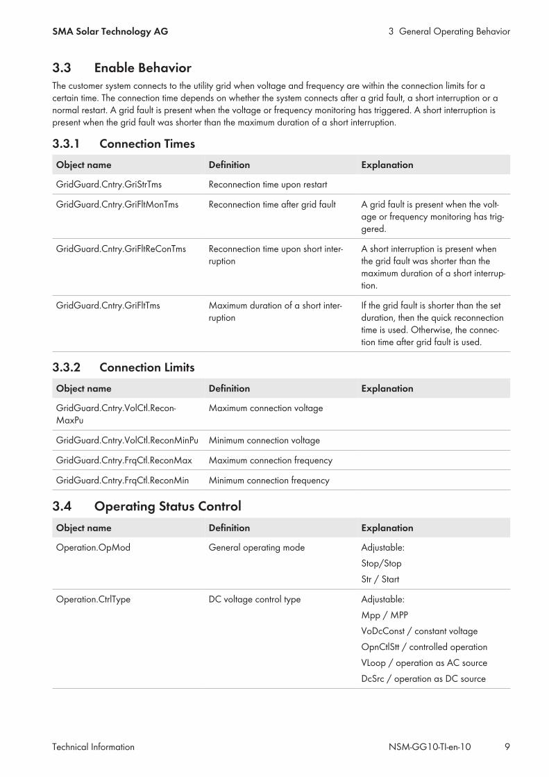
3.3 Enable BehaviorThe customer system connects to the utility grid when voltage and frequency are within the connection limits for acertain time. The connection time depends on whether the system connects after a grid fault, a short interruption or anormal restart. A grid fault is present when the voltage or frequency monitoring has triggered. A short interruption ispresent when the grid fault was shorter than the maximum duration of a short interruption.
3.3.1 Connection TimesObject name Definition Explanation
GridGuard.Cntry.GriStrTms Reconnection time upon restart
GridGuard.Cntry.GriFltMonTms Reconnection time after grid fault A grid fault is present when the volt-age or frequency monitoring has trig-gered.
GridGuard.Cntry.GriFltReConTms Reconnection time upon short inter-ruption
A short interruption is present whenthe grid fault was shorter than themaximum duration of a short interrup-tion.
GridGuard.Cntry.GriFltTms Maximum duration of a short inter-ruption
If the grid fault is shorter than the setduration, then the quick reconnectiontime is used. Otherwise, the connec-tion time after grid fault is used.
3.3.2 Connection LimitsObject name Definition Explanation
GridGuard.Cntry.VolCtl.Recon-MaxPu
Maximum connection voltage
GridGuard.Cntry.VolCtl.ReconMinPu Minimum connection voltage
GridGuard.Cntry.FrqCtl.ReconMax Maximum connection frequency
GridGuard.Cntry.FrqCtl.ReconMin Minimum connection frequency
3.4 Operating Status ControlObject name Definition Explanation
Operation.OpMod General operating mode Adjustable:Stop/StopStr / Start
Operation.CtrlType DC voltage control type Adjustable:Mpp / MPPVoDcConst / constant voltageOpnCtlStt / controlled operationVLoop / operation as AC sourceDcSrc / operation as DC source
3 General Operating Behavior SMA Solar Technology AG
Technical InformationNSM-GG10-TI-en-1010
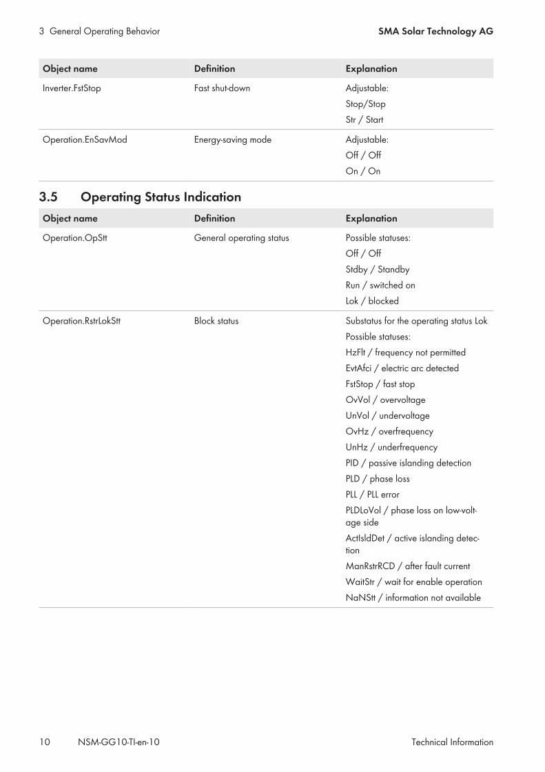
Object name Definition Explanation
Inverter.FstStop Fast shut-down Adjustable:Stop/StopStr / Start
Operation.EnSavMod Energy-saving mode Adjustable:Off / OffOn / On
3.5 Operating Status IndicationObject name Definition Explanation
Operation.OpStt General operating status Possible statuses:Off / OffStdby / StandbyRun / switched onLok / blocked
Operation.RstrLokStt Block status Substatus for the operating status LokPossible statuses:HzFlt / frequency not permittedEvtAfci / electric arc detectedFstStop / fast stopOvVol / overvoltageUnVol / undervoltageOvHz / overfrequencyUnHz / underfrequencyPID / passive islanding detectionPLD / phase lossPLL / PLL errorPLDLoVol / phase loss on low-volt-age sideActIsldDet / active islanding detec-tionManRstrRCD / after fault currentWaitStr / wait for enable operationNaNStt / information not available

3 General Operating BehaviorSMA Solar Technology AG
Technical Information 11NSM-GG10-TI-en-10
Object name Definition Explanation
Operation.StandbyStt Standby status Substatus for the operating statusStandbyPossible statuses:WaitPV / waiting for PV voltageWaitGri / waiting for valid AC gridEnSavMod / energy saving modeNaNStt / information not available
Operation.RunStt Operating status Substatus for the operating status"Run"Possible statuses:Mpp / MPP trackingVolDCConst / constant voltageBck / BackupShtdwn / shutdownDrt / deratingNaNStt / information not available
4 Behavior in Case of Undisturbed Utility Grid SMA Solar Technology AG
Technical InformationNSM-GG10-TI-en-1012
4 Behavior in Case of Undisturbed Utility Grid4.1 Active Power ModeThere are several active power modes that affect the active power flow of the customer system. One or two setpointinputs (e.g. for specifications from the market and grid) and one P(U) characteristic curve are implemented foroperation on the undisturbed utility grid. In case of frequency errors, the P(f) characteristic curve also applies (seeSection 5.2.2, page 34). The specifications resulting from these procedures are processed and prioritized in parallelas follows:
1. The minimum value is created from the maximum specifications
2. The maximum value is created from minimum specifications
3. In the case of conflicts, the specifications are taken into account in the following order:• Setpoint input 2 with high priority• Setpoint input 1 with high priority• P(V) Characteristic Curve• P(f) Characteristic Curve• Setpoint input 2 with low priority• Setpoint input 1 with low priority
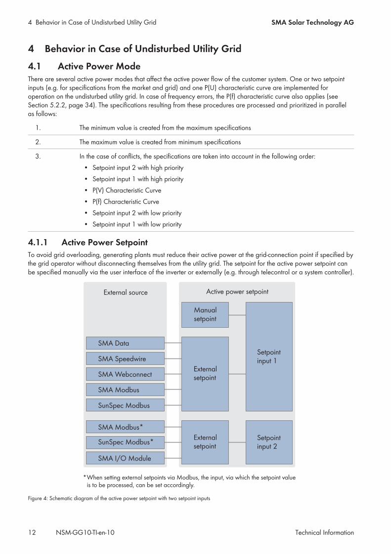
4.1.1 Active Power SetpointTo avoid grid overloading, generating plants must reduce their active power at the grid-connection point if specified bythe grid operator without disconnecting themselves from the utility grid. The setpoint for the active power setpoint canbe specified manually via the user interface of the inverter or externally (e.g. through telecontrol or a system controller).
SMA Data
SMA Speedwire
SMA Webconnect
SMA Modbus
SunSpec Modbus
SMA Modbus*
SMA I/O Module
SunSpec Modbus*
*When setting external setpoints via Modbus, the input, via which the setpoint value is to be processed, can be set accordingly.
Setpointinput 1
Manualsetpoint
Externalsetpoint
Externalsetpoint
Setpointinput 2
External source Active power setpoint
Figure 4: Schematic diagram of the active power setpoint with two setpoint inputs
4 Behavior in Case of Undisturbed Utility GridSMA Solar Technology AG
Technical Information 13NSM-GG10-TI-en-10
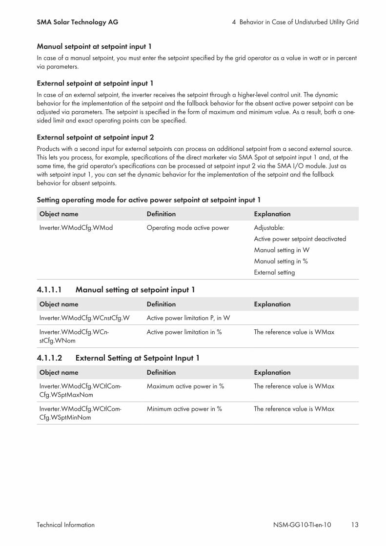
Manual setpoint at setpoint input 1In case of a manual setpoint, you must enter the setpoint specified by the grid operator as a value in watt or in percentvia parameters.
External setpoint at setpoint input 1In case of an external setpoint, the inverter receives the setpoint through a higher-level control unit. The dynamicbehavior for the implementation of the setpoint and the fallback behavior for the absent active power setpoint can beadjusted via parameters. The setpoint is specified in the form of maximum and minimum value. As a result, both a one-sided limit and exact operating points can be specified.
External setpoint at setpoint input 2Products with a second input for external setpoints can process an additional setpoint from a second external source.This lets you process, for example, specifications of the direct marketer via SMA Spot at setpoint input 1 and, at thesame time, the grid operator's specifications can be processed at setpoint input 2 via the SMA I/O module. Just aswith setpoint input 1, you can set the dynamic behavior for the implementation of the setpoint and the fallbackbehavior for absent setpoints.
Setting operating mode for active power setpoint at setpoint input 1
Object name Definition Explanation
Inverter.WModCfg.WMod Operating mode active power Adjustable:Active power setpoint deactivatedManual setting in WManual setting in %External setting
4.1.1.1 Manual setting at setpoint input 1
Object name Definition Explanation
Inverter.WModCfg.WCnstCfg.W Active power limitation P, in W
Inverter.WModCfg.WCn-stCfg.WNom
Active power limitation in % The reference value is WMax
4.1.1.2 External Setting at Setpoint Input 1
Object name Definition Explanation
Inverter.WModCfg.WCtlCom-Cfg.WSptMaxNom
Maximum active power in % The reference value is WMax
Inverter.WModCfg.WCtlCom-Cfg.WSptMinNom
Minimum active power in % The reference value is WMax
4 Behavior in Case of Undisturbed Utility Grid SMA Solar Technology AG
Technical InformationNSM-GG10-TI-en-1014
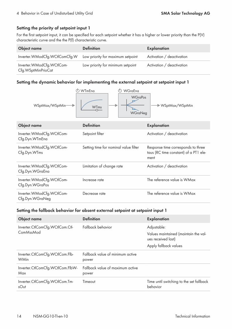
Setting the priority of setpoint input 1For the first setpoint input, it can be specified for each setpoint whether it has a higher or lower priority than the P(V)characteristic curve and the the P(f) characteristic curve.
Object name Definition Explanation
Inverter.WModCfg.WCtlComCfg.W Low priority for maximum setpoint Activation / deactivation
Inverter.WModCfg.WCtlCom-Cfg.WSptMinPrioCat
Low priority for minimum setpoint Activation / deactivation
Setting the dynamic behavior for implementing the external setpoint at setpoint input 1
WSptMax/WSptMin
WGraEnaWTmEna
WTms
WGraPos
WGraNeg
WSptMax/WSptMin
Object name Definition Explanation
Inverter.WModCfg.WCtlCom-Cfg.Dyn.WTmEna
Setpoint filter Activation / deactivation
Inverter.WModCfg.WCtlCom-Cfg.Dyn.WTms
Setting time for nominal value filter Response time corresponds to threetaus (RC time constant) of a PT1 ele-ment
Inverter.WModCfg.WCtlCom-Cfg.Dyn.WGraEna
Limitation of change rate Activation / deactivation
Inverter.WModCfg.WCtlCom-Cfg.Dyn.WGraPos
Increase rate The reference value is WMax
Inverter.WModCfg.WCtlCom-Cfg.Dyn.WGraNeg
Decrease rate The reference value is WMax
Setting the fallback behavior for absent external setpoint at setpoint input 1
Object name Definition Explanation
Inverter.CtlComCfg.WCtlCom.Ctl-ComMssMod
Fallback behavior Adjustable:Values maintained (maintain the val-ues received last)Apply fallback values
Inverter.CtlComCfg.WCtlCom.Flb-WMin
Fallback value of minimum activepower
Inverter.CtlComCfg.WCtlCom.FlbW-Max
Fallback value of maximum activepower
Inverter.CtlComCfg.WCtlCom.Tm-sOut
Timeout Time until switching to the set fallbackbehavior
4 Behavior in Case of Undisturbed Utility GridSMA Solar Technology AG
Technical Information 15NSM-GG10-TI-en-10
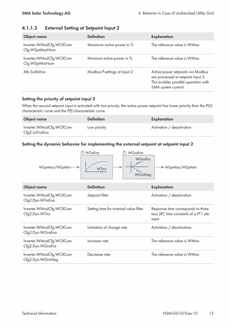
4.1.1.3 External Setting at Setpoint Input 2
Object name Definition Explanation
Inverter.WModCfg.WCtlCom-Cfg.WSptMaxNom
Maximum active power in % The reference value is WMax
Inverter.WModCfg.WCtlCom-Cfg.WSptMinNom
Minimum active power in % The reference value is WMax
Mb.ScdInEna Modbus P-settings at input 2 Active power setpoints via Modbusare processed at setpoint input 2.This enables parallel operation withSMA system control.
Setting the priority of setpoint input 2When the second setpoint input is activated with low priority, the active power setpoint has lower priority than the P(V)characteristic curve and the P(f) characteristic curve.
Object name Definition Explanation
Inverter.WModCfg.WCtlCom-Cfg2.LoPrioEna
Low priority Activation / deactivation
Setting the dynamic behavior for implementing the external setpoint at setpoint input 2
WSptMax/WSptMin
WGraEnaWTmEna
WTms
WGraPos
WGraNeg
WSptMax/WSptMin
Object name Definition Explanation
Inverter.WModCfg.WCtlCom-Cfg2.Dyn.WTmEna
Setpoint filter Activation / deactivation
Inverter.WModCfg.WCtlCom-Cfg2.Dyn.WTms
Setting time for nominal value filter Response time corresponds to threetaus (RC time constant) of a PT1 ele-ment
Inverter.WModCfg.WCtlCom-Cfg2.Dyn.WGraEna
Limitation of change rate Activation / deactivation
Inverter.WModCfg.WCtlCom-Cfg2.Dyn.WGraPos
Increase rate The reference value is WMax
Inverter.WModCfg.WCtlCom-Cfg2.Dyn.WGraNeg
Decrease rate The reference value is WMax
4 Behavior in Case of Undisturbed Utility Grid SMA Solar Technology AG
Technical InformationNSM-GG10-TI-en-1016
Setting the fallback behavior for absent external setpoint at setpoint input 2
Object name Definition Explanation
Inverter.CtlComCfg.WCtlCom2.Ctl-ComMssMod
Fallback behavior Adjustable:Values maintained (maintain the val-ues received last)Apply fallback values
Inverter.CtlComCfg.WCtlCom2.Flb-WMin
Fallback value of minimum activepower
Inverter.CtlComCfg.WCtlCom2.Flb-WMax
Fallback value of maximum activepower
Inverter.CtlComCfg.WCtlCom2.Tm-sOut
Timeout Time until switching to the set fallbackbehavior
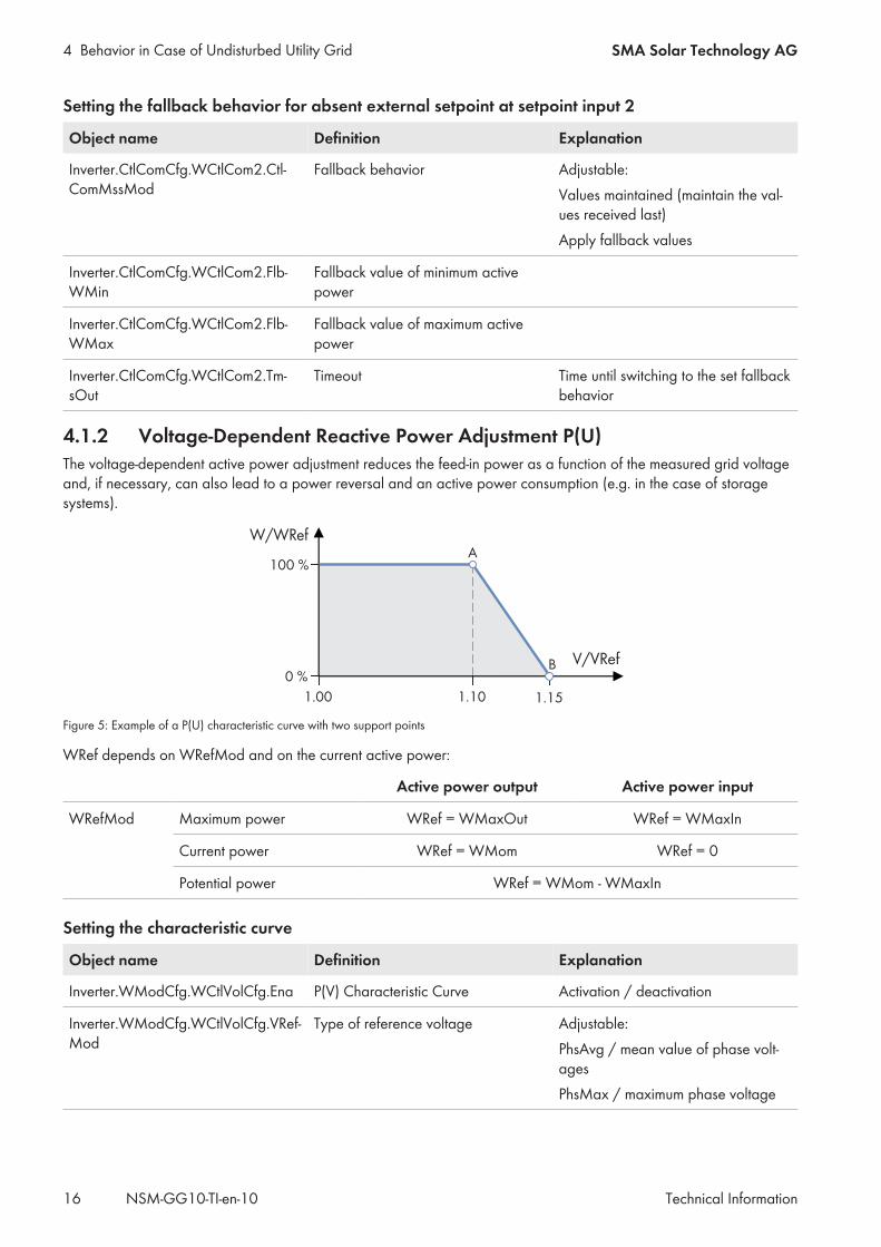
4.1.2 Voltage-Dependent Reactive Power Adjustment P(U)The voltage-dependent active power adjustment reduces the feed-in power as a function of the measured grid voltageand, if necessary, can also lead to a power reversal and an active power consumption (e.g. in the case of storagesystems).
W/WRefA
B
100 %
0 %V/VRef
1.10 1.151.00
Figure 5: Example of a P(U) characteristic curve with two support points
WRef depends on WRefMod and on the current active power:
Active power output Active power input
WRefMod Maximum power WRef = WMaxOut WRef = WMaxIn
Current power WRef = WMom WRef = 0
Potential power WRef = WMom - WMaxIn
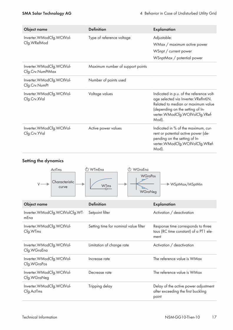
Setting the characteristic curve
Object name Definition Explanation
Inverter.WModCfg.WCtlVolCfg.Ena P(V) Characteristic Curve Activation / deactivation
Inverter.WModCfg.WCtlVolCfg.VRef-Mod
Type of reference voltage Adjustable:PhsAvg / mean value of phase volt-agesPhsMax / maximum phase voltage
4 Behavior in Case of Undisturbed Utility GridSMA Solar Technology AG
Technical Information 17NSM-GG10-TI-en-10
Object name Definition Explanation
Inverter.WModCfg.WCtlVol-Cfg.WRefMod
Type of reference voltage Adjustable:WMax / maximum active powerWSnpt / current powerWSnptMax / potential power
Inverter.WModCfg.WCtlVol-Cfg.Crv.NumPtMax
Maximum number of support points
Inverter.WModCfg.WCtlVol-Cfg.Crv.NumPt
Number of points used
Inverter.WModCfg.WCtlVol-Cfg.Crv.XVal
Voltage values Indicated in p.u. of the reference volt-age selected via Inverter.VRefIntLN.Related to median or maximum value(depending on the setting of In-verter.WModCfg.WCtlVolCfg.VRef-Mod).
Inverter.WModCfg.WCtlVol-Cfg.Crv.YVal
Active power values Indicated in % of the maximum, cur-rent or potential active power (de-pending on the setting of In-verter.WModCfg.WCtlVolCfg.WRef-Mod).
Setting the dynamics
V
ActTms WGraEnaWTmEna
WTms
WGraPos
WGraNeg
WSptMax/MSptMinCharacteristic
curve
Object name Definition Explanation
Inverter.WModCfg.WCtlVolCfg.WT-mEna
Setpoint filter Activation / deactivation
Inverter.WModCfg.WCtlVol-Cfg.WTms
Setting time for nominal value filter Response time corresponds to threetaus (RC time constant) of a PT1 ele-ment
Inverter.WModCfg.WCtlVol-Cfg.WGraEna
Limitation of change rate Activation / deactivation
Inverter.WModCfg.WCtlVol-Cfg.WGraPos
Increase rate The reference value is WMax
Inverter.WModCfg.WCtlVol-Cfg.WGraNeg
Decrease rate The reference value is WMax
Inverter.WModCfg.WCtlVol-Cfg.ActTms
Tripping delay Delay of the active power adjustmentafter exceeding the first bucklingpoint
4 Behavior in Case of Undisturbed Utility Grid SMA Solar Technology AG
Technical InformationNSM-GG10-TI-en-1018
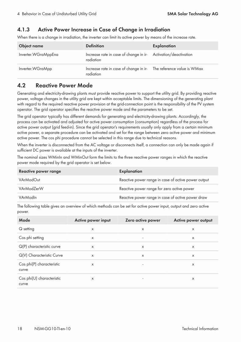
4.1.3 Active Power Increase in Case of Change in IrradiationWhen there is a change in irradiation, the inverter can limit its active power by means of the increase rate.
Object name Definition Explanation
Inverter.WGraMppEna Increase rate in case of change in ir-radiation
Activation/deactivation
Inverter.WGraMpp Increase rate in case of change in ir-radiation
The reference value is WMax
4.2 Reactive Power ModeGenerating and electricity-drawing plants must provide reactive power to support the utility grid. By providing reactivepower, voltage changes in the utility grid are kept within acceptable limits. The dimensioning of the generating plantwith regard to the required reactive power provision at the grid-connection point is the responsibility of the PV systemoperator. The grid operator specifies the reactive power mode and the parameters to be set.The grid operator typically has different demands for generating and electricity-drawing plants. Accordingly, theprocess can be activated and adjusted for active power consumption (consumption) regardless of the process foractive power output (grid feed-in). Since the grid operator's requirements usually only apply from a certain minimumactive power, a separate procedure can be activated and set for the range between zero active power and minimumactive power. The cos phi procedure cannot be selected in this range due to technical reasons.When the inverter is disconnected from the AC voltage or disconnects itself, a connection can only be made again ifsufficient DC power is available at the inputs of the inverter.The nominal sizes WMinIn and WMinOut form the limits to the three reactive power ranges in which the reactivepower mode required by the grid operator is set below.
Reactive power range Explanation
VArModOut Reactive power range in case of active power output
VArModZerW Reactive power range for zero active power
VArModIn Reactive power range in case of active power draw
The following table gives an overview of which methods can be set for active power input, output and zero activepower.
Mode Active power input Zero active power Active power output
Q setting x x x
Cos phi setting x - x
Q(P) characteristic curve x x x
Q(V) Characteristic Curve x x x
Cos phi(P) characteristiccurve
x - x
Cos phi(U) characteristiccurve
x - x
4 Behavior in Case of Undisturbed Utility GridSMA Solar Technology AG
Technical Information 19NSM-GG10-TI-en-10
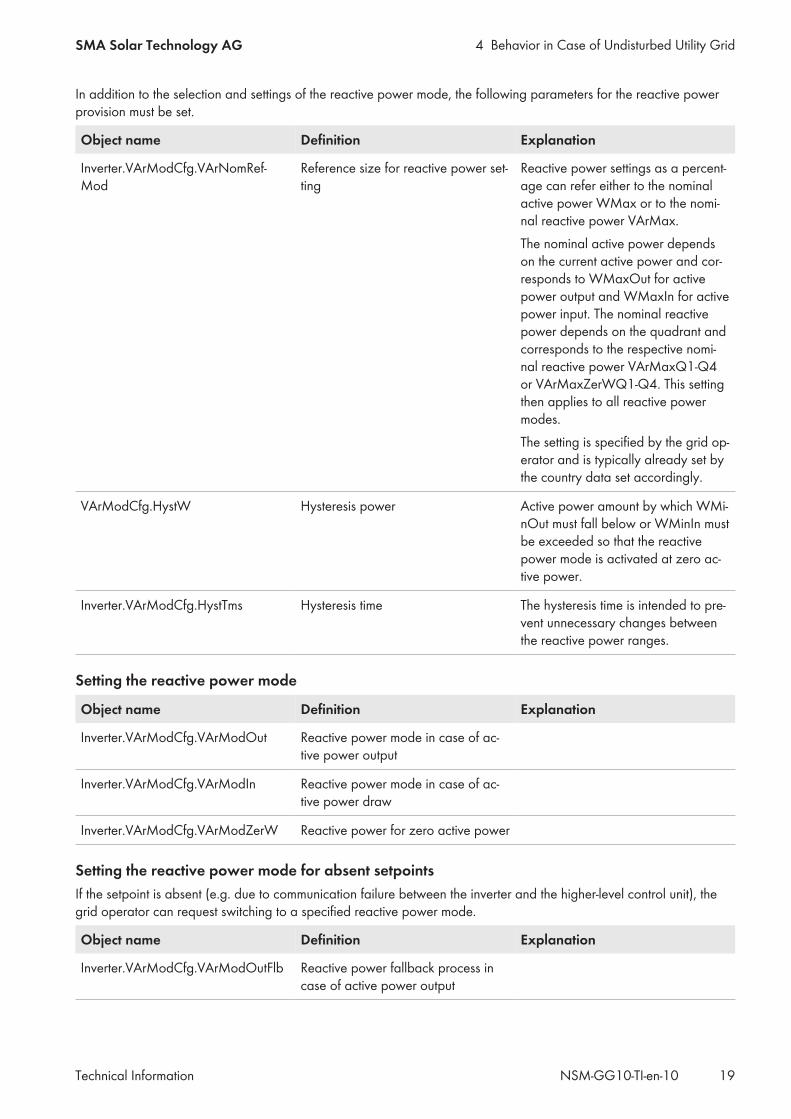
In addition to the selection and settings of the reactive power mode, the following parameters for the reactive powerprovision must be set.
Object name Definition Explanation
Inverter.VArModCfg.VArNomRef-Mod
Reference size for reactive power set-ting
Reactive power settings as a percent-age can refer either to the nominalactive power WMax or to the nomi-nal reactive power VArMax.The nominal active power dependson the current active power and cor-responds to WMaxOut for activepower output and WMaxIn for activepower input. The nominal reactivepower depends on the quadrant andcorresponds to the respective nomi-nal reactive power VArMaxQ1-Q4or VArMaxZerWQ1-Q4. This settingthen applies to all reactive powermodes.The setting is specified by the grid op-erator and is typically already set bythe country data set accordingly.
VArModCfg.HystW Hysteresis power Active power amount by which WMi-nOut must fall below or WMinIn mustbe exceeded so that the reactivepower mode is activated at zero ac-tive power.
Inverter.VArModCfg.HystTms Hysteresis time The hysteresis time is intended to pre-vent unnecessary changes betweenthe reactive power ranges.
Setting the reactive power mode
Object name Definition Explanation
Inverter.VArModCfg.VArModOut Reactive power mode in case of ac-tive power output
Inverter.VArModCfg.VArModIn Reactive power mode in case of ac-tive power draw
Inverter.VArModCfg.VArModZerW Reactive power for zero active power
Setting the reactive power mode for absent setpointsIf the setpoint is absent (e.g. due to communication failure between the inverter and the higher-level control unit), thegrid operator can request switching to a specified reactive power mode.
Object name Definition Explanation
Inverter.VArModCfg.VArModOutFlb Reactive power fallback process incase of active power output
4 Behavior in Case of Undisturbed Utility Grid SMA Solar Technology AG
Technical InformationNSM-GG10-TI-en-1020
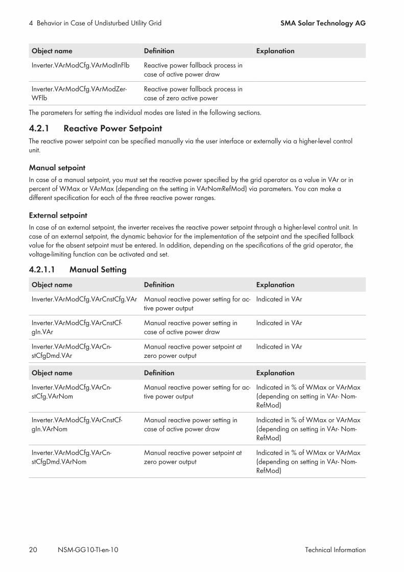
Object name Definition Explanation
Inverter.VArModCfg.VArModInFlb Reactive power fallback process incase of active power draw
Inverter.VArModCfg.VArModZer-WFlb
Reactive power fallback process incase of zero active power
The parameters for setting the individual modes are listed in the following sections.
4.2.1 Reactive Power SetpointThe reactive power setpoint can be specified manually via the user interface or externally via a higher-level controlunit.
Manual setpointIn case of a manual setpoint, you must set the reactive power specified by the grid operator as a value in VAr or inpercent of WMax or VArMax (depending on the setting in VArNomRefMod) via parameters. You can make adifferent specification for each of the three reactive power ranges.
External setpointIn case of an external setpoint, the inverter receives the reactive power setpoint through a higher-level control unit. Incase of an external setpoint, the dynamic behavior for the implementation of the setpoint and the specified fallbackvalue for the absent setpoint must be entered. In addition, depending on the specifications of the grid operator, thevoltage-limiting function can be activated and set.
4.2.1.1 Manual Setting
Object name Definition Explanation
Inverter.VArModCfg.VArCnstCfg.VAr Manual reactive power setting for ac-tive power output
Indicated in VAr
Inverter.VArModCfg.VArCnstCf-gIn.VAr
Manual reactive power setting incase of active power draw
Indicated in VAr
Inverter.VArModCfg.VArCn-stCfgDmd.VAr
Manual reactive power setpoint atzero power output
Indicated in VAr
Object name Definition Explanation
Inverter.VArModCfg.VArCn-stCfg.VArNom
Manual reactive power setting for ac-tive power output
Indicated in % of WMax or VArMax(depending on setting in VAr- Nom-RefMod)
Inverter.VArModCfg.VArCnstCf-gIn.VArNom
Manual reactive power setting incase of active power draw
Indicated in % of WMax or VArMax(depending on setting in VAr- Nom-RefMod)
Inverter.VArModCfg.VArCn-stCfgDmd.VArNom
Manual reactive power setpoint atzero power output
Indicated in % of WMax or VArMax(depending on setting in VAr- Nom-RefMod)
4 Behavior in Case of Undisturbed Utility GridSMA Solar Technology AG
Technical Information 21NSM-GG10-TI-en-10
4.2.1.2 External Setting
Object name Definition Explanation
Inverter.VArModCfg.VArCtlCom-Cfg.VArNomPrc
Reactive power setpoint Q The reference value is WMax or VAr-Max (depending on setting inVArNomRefMod)
Setting fallback value for absent external setpoint
Object name Definition Explanation
Inverter.CtlComCfg.VArCtlCom.Ctl-ComMssMod
Fallback behavior Adjustable:UsStp / values maintained (maintainthe values received last)UsFlb / apply fallback values
Inverter.CtlComCfg.VArCtlCom.Flb-VArNom
Fallback value
Inverter.CtlComCfg.VArCtlCom.Tm-sOut
Timeout Time until switching to the set fallbackbehavior
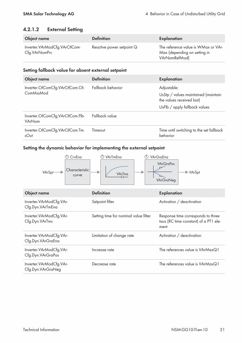
Setting the dynamic behavior for implementing the external setpoint
VArSpt
VArGraEnaVArTmEna
VArTms
VArGraPos
VArGraNeg
VArSpt
CrvEna
Characteristiccurve
Object name Definition Explanation
Inverter.VArModCfg.VAr-Cfg.Dyn.VArTmEna
Setpoint filter Activation / deactivation
Inverter.VArModCfg.VAr-Cfg.Dyn.VArTms
Setting time for nominal value filter Response time corresponds to threetaus (RC time constant) of a PT1 ele-ment
Inverter.VArModCfg.VAr-Cfg.Dyn.VArGraEna
Limitation of change rate Activation / deactivation
Inverter.VArModCfg.VAr-Cfg.Dyn.VArGraPos
Increase rate The references value is VArMaxQ1
Inverter.VArModCfg.VAr-Cfg.Dyn.VArGraNeg
Decrease rate The references value is VArMaxQ1
4 Behavior in Case of Undisturbed Utility Grid SMA Solar Technology AG
Technical InformationNSM-GG10-TI-en-1022
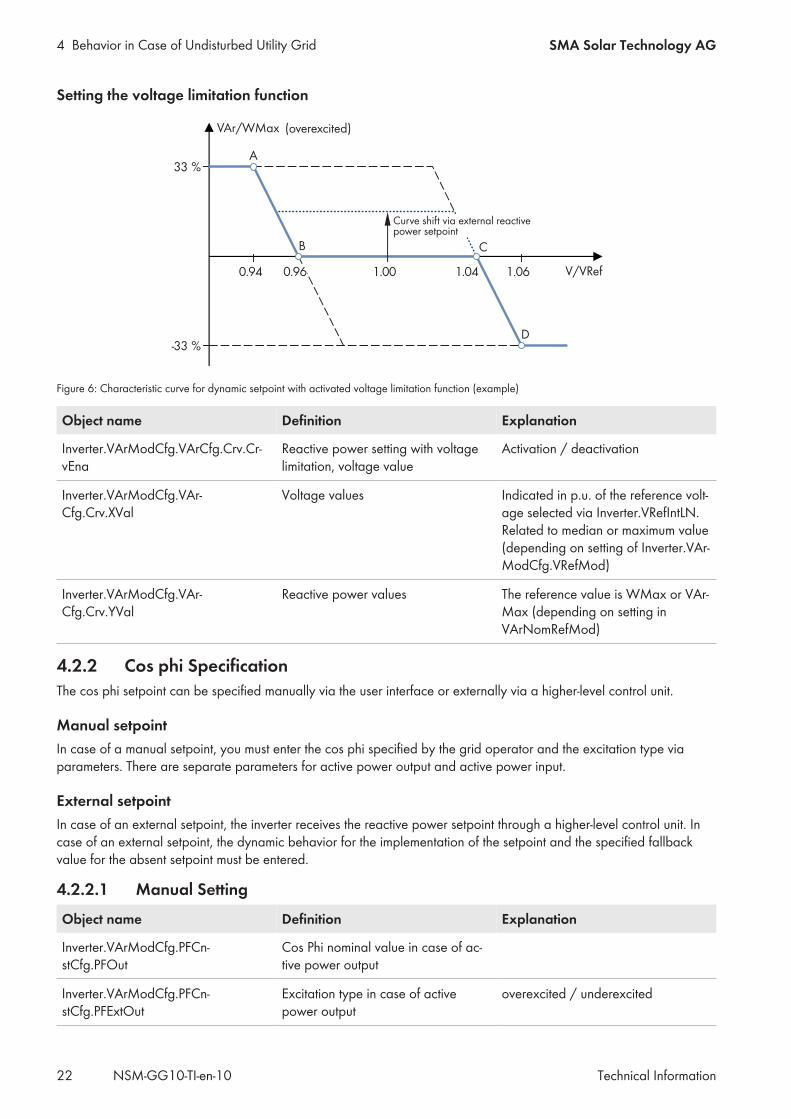
Setting the voltage limitation function
-33 %D
33 %
VAr/WMax
C
A
B
V/VRef
(overexcited)
0.94 1.00 1.061.040.96
Curve shift via external reactive power setpoint
Figure 6: Characteristic curve for dynamic setpoint with activated voltage limitation function (example)
Object name Definition Explanation
Inverter.VArModCfg.VArCfg.Crv.Cr-vEna
Reactive power setting with voltagelimitation, voltage value
Activation / deactivation
Inverter.VArModCfg.VAr-Cfg.Crv.XVal
Voltage values Indicated in p.u. of the reference volt-age selected via Inverter.VRefIntLN.Related to median or maximum value(depending on setting of Inverter.VAr-ModCfg.VRefMod)
Inverter.VArModCfg.VAr-Cfg.Crv.YVal
Reactive power values The reference value is WMax or VAr-Max (depending on setting inVArNomRefMod)
4.2.2 Cos phi SpecificationThe cos phi setpoint can be specified manually via the user interface or externally via a higher-level control unit.
Manual setpointIn case of a manual setpoint, you must enter the cos phi specified by the grid operator and the excitation type viaparameters. There are separate parameters for active power output and active power input.
External setpointIn case of an external setpoint, the inverter receives the reactive power setpoint through a higher-level control unit. Incase of an external setpoint, the dynamic behavior for the implementation of the setpoint and the specified fallbackvalue for the absent setpoint must be entered.
4.2.2.1 Manual Setting
Object name Definition Explanation
Inverter.VArModCfg.PFCn-stCfg.PFOut
Cos Phi nominal value in case of ac-tive power output
Inverter.VArModCfg.PFCn-stCfg.PFExtOut
Excitation type in case of activepower output
overexcited / underexcited
4 Behavior in Case of Undisturbed Utility GridSMA Solar Technology AG
Technical Information 23NSM-GG10-TI-en-10
Object name Definition Explanation
Inverter.VArModCfg.PFCnstCfg.PFIn Cos Phi nominal value in case of ac-tive power draw
Inverter.VArModCfg.PFCnstCfg.PFEx-tIn
Excitation type in case of activepower draw
overexcited / underexcited
4.2.2.2 External Setting
Setpoint
Object name Definition Explanation
Inverter.VArModCfg.PFCtlComCfg.PF Cos Phi nominal value in case of ac-tive power output
Inverter.VArModCfg.PFCtlCom-Cfg.PFExt
Excitation type in case of activepower output
underexcited/overexcited
Inverter.VArModCfg.PFCtlCom-Cfg.PFIn
Cos Phi nominal value in case of ac-tive power draw
Inverter.VArModCfg.PFCtlCom-Cfg.PFExtIn
Excitation type in case of activepower draw
underexcited/overexcited
Setting fallback value for absent external setpoint
Object name Definition Explanation
Inverter.CtlComCfg.PFCtlCom.Ctl-ComMssMod
Fallback behavior Adjustable:Values maintained (maintain the val-ues received last)Apply fallback values
Inverter.CtlComCfg.PFCtlCom.FlbPF Fallback value of Cos Phi in case ofactive power output
Inverter.CtlComCfg.PFCtl-Com.FlbPFExt
Fallback value of excitation type incase of active power output
underexcited/overexcited
Inverter.CtlComCfg.PFCtlCom.FlbPFIn Fallback value of Cos Phi in case ofactive power draw
Inverter.CtlComCfg.PFCtl-Com.FlbPFExtIn
Fallback value of excitation type incase of active power draw
underexcited/overexcited
Inverter.CtlComCfg.PFCtlCom.Tm-sOut
Timeout Time until switching to the set fallbackbehavior
4 Behavior in Case of Undisturbed Utility Grid SMA Solar Technology AG
Technical InformationNSM-GG10-TI-en-1024
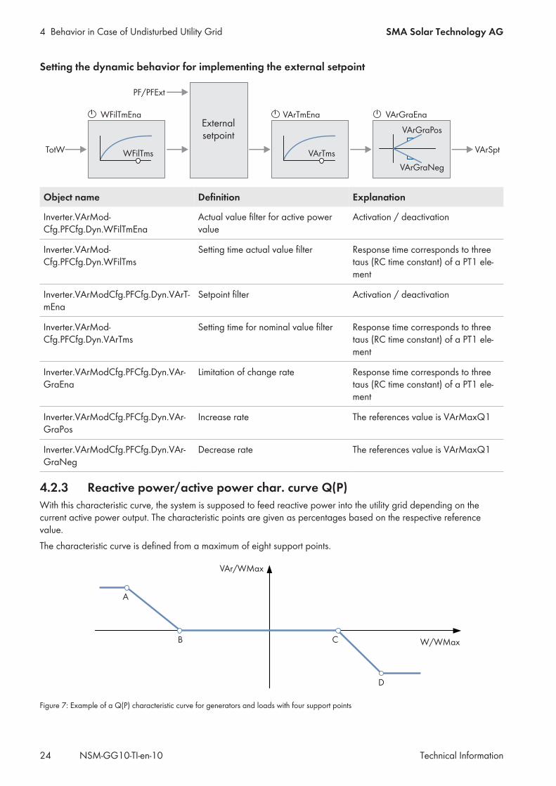
Setting the dynamic behavior for implementing the external setpoint
TotW WFilTms
WFilTmEna VArGraEnaVArTmEna
VArTms
VArGraPos
VArGraNeg
VArSpt
PF/PFExt
Externalsetpoint
Object name Definition Explanation
Inverter.VArMod-Cfg.PFCfg.Dyn.WFilTmEna
Actual value filter for active powervalue
Activation / deactivation
Inverter.VArMod-Cfg.PFCfg.Dyn.WFilTms
Setting time actual value filter Response time corresponds to threetaus (RC time constant) of a PT1 ele-ment
Inverter.VArModCfg.PFCfg.Dyn.VArT-mEna
Setpoint filter Activation / deactivation
Inverter.VArMod-Cfg.PFCfg.Dyn.VArTms
Setting time for nominal value filter Response time corresponds to threetaus (RC time constant) of a PT1 ele-ment
Inverter.VArModCfg.PFCfg.Dyn.VAr-GraEna
Limitation of change rate Response time corresponds to threetaus (RC time constant) of a PT1 ele-ment
Inverter.VArModCfg.PFCfg.Dyn.VAr-GraPos
Increase rate The references value is VArMaxQ1
Inverter.VArModCfg.PFCfg.Dyn.VAr-GraNeg
Decrease rate The references value is VArMaxQ1
4.2.3 Reactive power/active power char. curve Q(P)With this characteristic curve, the system is supposed to feed reactive power into the utility grid depending on thecurrent active power output. The characteristic points are given as percentages based on the respective referencevalue.The characteristic curve is defined from a maximum of eight support points.
A
B C
D
W/WMax
VAr/WMax
Figure 7: Example of a Q(P) characteristic curve for generators and loads with four support points
4 Behavior in Case of Undisturbed Utility GridSMA Solar Technology AG
Technical Information 25NSM-GG10-TI-en-10
AB
C
VAr/WMax
W/WMax
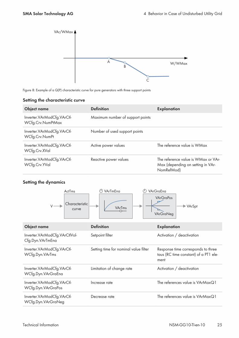
Figure 8: Example of a Q(P) characteristic curve for pure generators with three support points
Setting the characteristic curve
Object name Definition Explanation
Inverter.VArModCfg.VArCtl-WCfg.Crv.NumPtMax
Maximum number of support points
Inverter.VArModCfg.VArCtl-WCfg.Crv.NumPt
Number of used support points
Inverter.VArModCfg.VArCtl-WCfg.Crv.XVal
Active power values The reference value is WMax
Inverter.VArModCfg.VArCtl-WCfg.Crv.YVal
Reactive power values The reference value is WMax or VAr-Max (depending on setting in VAr-NomRefMod)
Setting the dynamics
V
ActTms VArGraEnaVArTmEna
VArTms
VArGraPos
VArGraNeg
VArSptCharacteristic
curve
Object name Definition Explanation
Inverter.VArModCfg.VArCtlVol-Cfg.Dyn.VArTmEna
Setpoint filter Activation / deactivation
Inverter.VArModCfg.VArCtl-WCfg.Dyn.VArTms
Setting time for nominal value filter Response time corresponds to threetaus (RC time constant) of a PT1 ele-ment
Inverter.VArModCfg.VArCtl-WCfg.Dyn.VArGraEna
Limitation of change rate Activation / deactivation
Inverter.VArModCfg.VArCtl-WCfg.Dyn.VArGraPos
Increase rate The references value is VArMaxQ1
Inverter.VArModCfg.VArCtl-WCfg.Dyn.VArGraNeg
Decrease rate The references value is VArMaxQ1
4 Behavior in Case of Undisturbed Utility Grid SMA Solar Technology AG
Technical InformationNSM-GG10-TI-en-1026
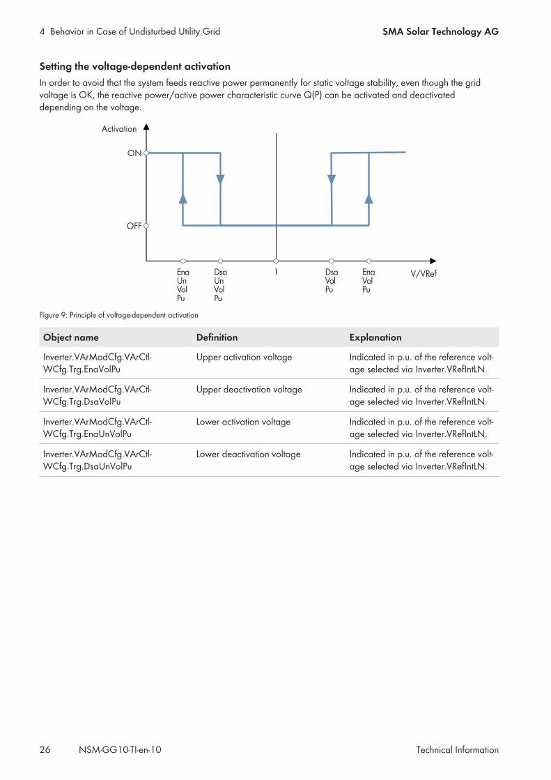
Setting the voltage-dependent activationIn order to avoid that the system feeds reactive power permanently for static voltage stability, even though the gridvoltage is OK, the reactive power/active power characteristic curve Q(P) can be activated and deactivateddepending on the voltage.
EnaUnVolPu
DsaUnVolPu
DsaVolPu
EnaVolPu
1
ON
OFF
V/VRef
Activation
Figure 9: Principle of voltage-dependent activation
Object name Definition Explanation
Inverter.VArModCfg.VArCtl-WCfg.Trg.EnaVolPu
Upper activation voltage Indicated in p.u. of the reference volt-age selected via Inverter.VRefIntLN.
Inverter.VArModCfg.VArCtl-WCfg.Trg.DsaVolPu
Upper deactivation voltage Indicated in p.u. of the reference volt-age selected via Inverter.VRefIntLN.
Inverter.VArModCfg.VArCtl-WCfg.Trg.EnaUnVolPu
Lower activation voltage Indicated in p.u. of the reference volt-age selected via Inverter.VRefIntLN.
Inverter.VArModCfg.VArCtl-WCfg.Trg.DsaUnVolPu
Lower deactivation voltage Indicated in p.u. of the reference volt-age selected via Inverter.VRefIntLN.
4 Behavior in Case of Undisturbed Utility GridSMA Solar Technology AG
Technical Information 27NSM-GG10-TI-en-10
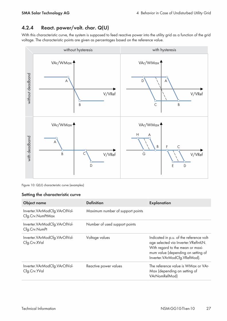
4.2.4 React. power/volt. char. Q(U)With this characteristic curve, the system is supposed to feed reactive power into the utility grid as a function of the gridvoltage. The characteristic points are given as percentages based on the reference value.
A
B
VAr/WMax
D
B
VAr/WMax
A
C
C
D
VAr/WMax
D
B
VAr/WMax
A
C
A
B
F
E
H
G
with
dea
db
and
without hysteresis
with
out
dea
db
and
V/VRef V/VRef
with hysteresis
V/VRef V/VRef
Figure 10: Q(U) characteristic curve (examples)
Setting the characteristic curve
Object name Definition Explanation
Inverter.VArModCfg.VArCtlVol-Cfg.Crv.NumPtMax
Maximum number of support points
Inverter.VArModCfg.VArCtlVol-Cfg.Crv.NumPt
Number of used support points
Inverter.VArModCfg.VArCtlVol-Cfg.Crv.XVal
Voltage values Indicated in p.u. of the reference volt-age selected via Inverter.VRefIntLN.With regard to the mean or maxi-mum value (depending on setting ofInverter.VArModCfg.VRefMod).
Inverter.VArModCfg.VArCtlVol-Cfg.Crv.YVal
Reactive power values The reference value is WMax or VAr-Max (depending on setting ofVArNomRefMod)
4 Behavior in Case of Undisturbed Utility Grid SMA Solar Technology AG
Technical InformationNSM-GG10-TI-en-1028
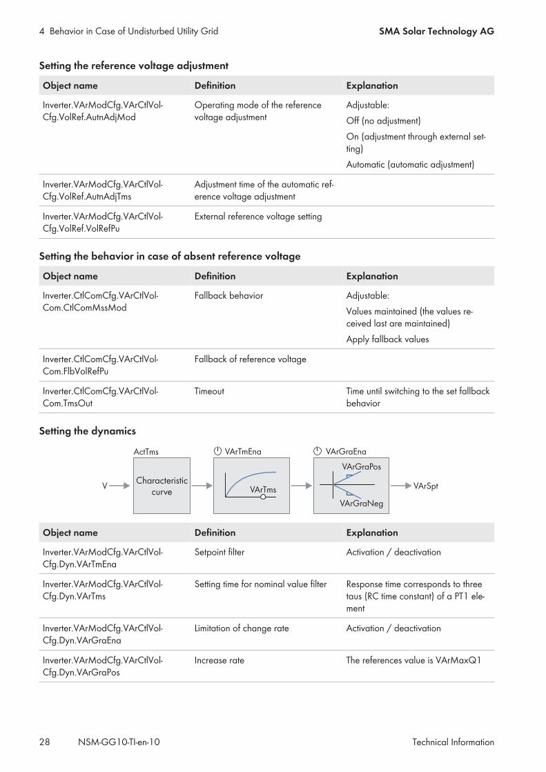
Setting the reference voltage adjustment
Object name Definition Explanation
Inverter.VArModCfg.VArCtlVol-Cfg.VolRef.AutnAdjMod
Operating mode of the referencevoltage adjustment
Adjustable:Off (no adjustment)On (adjustment through external set-ting)Automatic (automatic adjustment)
Inverter.VArModCfg.VArCtlVol-Cfg.VolRef.AutnAdjTms
Adjustment time of the automatic ref-erence voltage adjustment
Inverter.VArModCfg.VArCtlVol-Cfg.VolRef.VolRefPu
External reference voltage setting
Setting the behavior in case of absent reference voltage
Object name Definition Explanation
Inverter.CtlComCfg.VArCtlVol-Com.CtlComMssMod
Fallback behavior Adjustable:Values maintained (the values re-ceived last are maintained)Apply fallback values
Inverter.CtlComCfg.VArCtlVol-Com.FlbVolRefPu
Fallback of reference voltage
Inverter.CtlComCfg.VArCtlVol-Com.TmsOut
Timeout Time until switching to the set fallbackbehavior
Setting the dynamics
V
ActTms VArGraEnaVArTmEna
VArTms
VArGraPos
VArGraNeg
VArSptCharacteristic
curve
Object name Definition Explanation
Inverter.VArModCfg.VArCtlVol-Cfg.Dyn.VArTmEna
Setpoint filter Activation / deactivation
Inverter.VArModCfg.VArCtlVol-Cfg.Dyn.VArTms
Setting time for nominal value filter Response time corresponds to threetaus (RC time constant) of a PT1 ele-ment
Inverter.VArModCfg.VArCtlVol-Cfg.Dyn.VArGraEna
Limitation of change rate Activation / deactivation
Inverter.VArModCfg.VArCtlVol-Cfg.Dyn.VArGraPos
Increase rate The references value is VArMaxQ1
4 Behavior in Case of Undisturbed Utility GridSMA Solar Technology AG
Technical Information 29NSM-GG10-TI-en-10
Object name Definition Explanation
Inverter.VArModCfg.VArCtlVol-Cfg.Dyn.VArGraNeg
Decrease rate The references value is VArMaxQ1
Inverter.VArModCfg.VArCtlVol-Cfg.Dyn.ActTms
Tripping delay
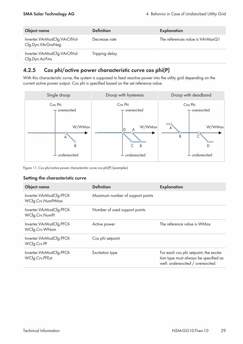
4.2.5 Cos phi/active power characteristic curve cos phi(P)With this characteristic curve, the system is supposed to feed reactive power into the utility grid depending on thecurrent active power output. Cos phi is specified based on the set reference value.
Cos Phi
A
B
Cos Phi
D
C
A
B
Cos Phi
D
A
B C
W/WMax W/WMax W/WMax
Single droop
overexcited
Droop with hysteresis Droop with deadband
underexcited
overexcited
underexcited
overexcited
underexcited
Figure 11: Cos phi/active power characteristic curve cos phi(P) (examples)
Setting the characteristic curve
Object name Definition Explanation
Inverter.VArModCfg.PFCtl-WCfg.Crv.NumPtMax
Maximum number of support points
Inverter.VArModCfg.PFCtl-WCfg.Crv.NumPt
Number of used support points
Inverter.VArModCfg.PFCtl-WCfg.Crv.WNom
Active power The reference value is WMax
Inverter.VArModCfg.PFCtl-WCfg.Crv.PF
Cos phi setpoint
Inverter.VArModCfg.PFCtl-WCfg.Crv.PFExt
Excitation type For each cos phi setpoint, the excita-tion type must always be specified aswell: underexcited / overexcited
4 Behavior in Case of Undisturbed Utility Grid SMA Solar Technology AG
Technical InformationNSM-GG10-TI-en-1030
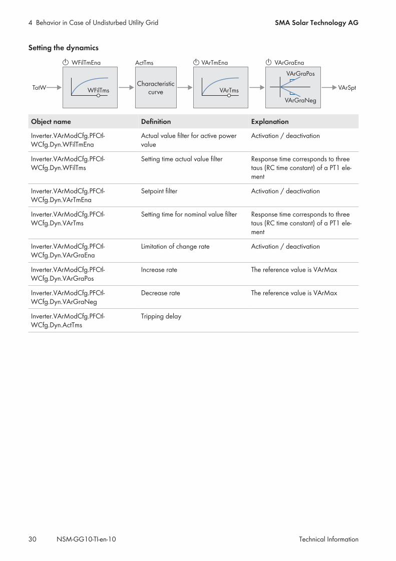
Setting the dynamics
TotW WFilTms
WFilTmEna ActTms VArGraEnaVArTmEna
VArTms
VArGraPos
VArGraNeg
VArSptCharacteristic
curve
Object name Definition Explanation
Inverter.VArModCfg.PFCtl-WCfg.Dyn.WFilTmEna
Actual value filter for active powervalue
Activation / deactivation
Inverter.VArModCfg.PFCtl-WCfg.Dyn.WFilTms
Setting time actual value filter Response time corresponds to threetaus (RC time constant) of a PT1 ele-ment
Inverter.VArModCfg.PFCtl-WCfg.Dyn.VArTmEna
Setpoint filter Activation / deactivation
Inverter.VArModCfg.PFCtl-WCfg.Dyn.VArTms
Setting time for nominal value filter Response time corresponds to threetaus (RC time constant) of a PT1 ele-ment
Inverter.VArModCfg.PFCtl-WCfg.Dyn.VArGraEna
Limitation of change rate Activation / deactivation
Inverter.VArModCfg.PFCtl-WCfg.Dyn.VArGraPos
Increase rate The reference value is VArMax
Inverter.VArModCfg.PFCtl-WCfg.Dyn.VArGraNeg
Decrease rate The reference value is VArMax
Inverter.VArModCfg.PFCtl-WCfg.Dyn.ActTms
Tripping delay
4 Behavior in Case of Undisturbed Utility GridSMA Solar Technology AG
Technical Information 31NSM-GG10-TI-en-10
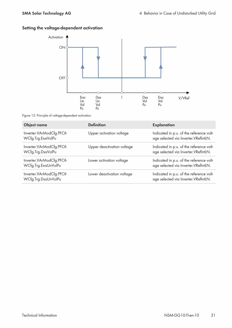
Setting the voltage-dependent activation
EnaUnVolPu
DsaUnVolPu
DsaVolPu
EnaVolPu
1
ON
OFF
V/VRef
Activation
Figure 12: Principle of voltage-dependent activation
Object name Definition Explanation
Inverter.VArModCfg.PFCtl-WCfg.Trg.EnaVolPu
Upper activation voltage Indicated in p.u. of the reference volt-age selected via Inverter.VRefIntLN.
Inverter.VArModCfg.PFCtl-WCfg.Trg.DsaVolPu
Upper deactivation voltage Indicated in p.u. of the reference volt-age selected via Inverter.VRefIntLN.
Inverter.VArModCfg.PFCtl-WCfg.Trg.EnaUnVolPu
Lower activation voltage Indicated in p.u. of the reference volt-age selected via Inverter.VRefIntLN.
Inverter.VArModCfg.PFCtl-WCfg.Trg.DsaUnVolPu
Lower deactivation voltage Indicated in p.u. of the reference volt-age selected via Inverter.VRefIntLN.
5 Behavior in case of disturbed utility grid SMA Solar Technology AG
Technical InformationNSM-GG10-TI-en-1032
5 Behavior in case of disturbed utility grid5.1 Behavior in case of voltage errors
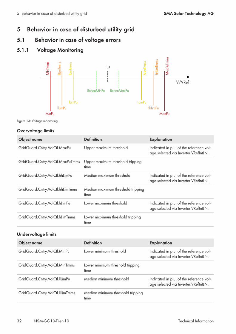
5.1.1 Voltage Monitoring
MaxPu
MaxPuTm
ms
hhLimPu
hhLim
Tmms
hLimPu
hLimTm
ms
MinPu
MinTm
ms
llLimPu
llLimTm
ms
lLimTm
ms
lLimPu
ReconMinPu ReconMaxPu
V/VRef
1.0
Figure 13: Voltage monitoring
Overvoltage limits
Object name Definition Explanation
GridGuard.Cntry.VolCtl.MaxPu Upper maximum threshold Indicated in p.u. of the reference volt-age selected via Inverter.VRefIntLN.
GridGuard.Cntry.VolCtl.MaxPuTmms Upper maximum threshold trippingtime
GridGuard.Cntry.VolCtl.hhLimPu Median maximum threshold Indicated in p.u. of the reference volt-age selected via Inverter.VRefIntLN.
GridGuard.Cntry.VolCtl.hhLimTmms Median maximum threshold trippingtime
GridGuard.Cntry.VolCtl.hLimPu Lower maximum threshold Indicated in p.u. of the reference volt-age selected via Inverter.VRefIntLN.
GridGuard.Cntry.VolCtl.hLimTmms Lower maximum threshold trippingtime
Undervoltage limits
Object name Definition Explanation
GridGuard.Cntry.VolCtl.MinPu Lower minimum threshold Indicated in p.u. of the reference volt-age selected via Inverter.VRefIntLN.
GridGuard.Cntry.VolCtl.MinTmms Lower minimum threshold trippingtime
GridGuard.Cntry.VolCtl.llLimPu Median minimum threshold Indicated in p.u. of the reference volt-age selected via Inverter.VRefIntLN.
GridGuard.Cntry.VolCtl.llLimTmms Median minimum threshold trippingtime
5 Behavior in case of disturbed utility gridSMA Solar Technology AG
Technical Information 33NSM-GG10-TI-en-10
Object name Definition Explanation
GridGuard.Cntry.VolCtl.lLimPu Upper minimum threshold Indicated in p.u. of the reference volt-age selected via Inverter.VRefIntLN.
GridGuard.Cntry.VolCtl.lLimTmms Upper minimum threshold trippingtime
5.1.2 Dynamic Grid SupportWith dynamic grid support, the inverter supports the utility grid during a brief grid-voltage dip or during a short periodof overvoltage. With full dynamic grid support, grid support is ensured by providing reactive power. With limiteddynamic grid support, the feed-in operation is interrupted during a grid instability, but without the inverter disconnectingfrom the utility grid.The grid limits and deactivation delays are set by default according to the local grid connection regulations whenselecting the country data set. When the full dynamic grid support is activated, the islanding detection cannot beactivated at the same time. Both functions cannot be used simultaneously.
Object name Definition Explanation
Inverter.DGSModCfg.DGSMod Dynamic grid support operatingmode
Adjustable:OffLimited dynamic grid supportComplete dynamic grid support
5.2 Behavior in case of frequency errors
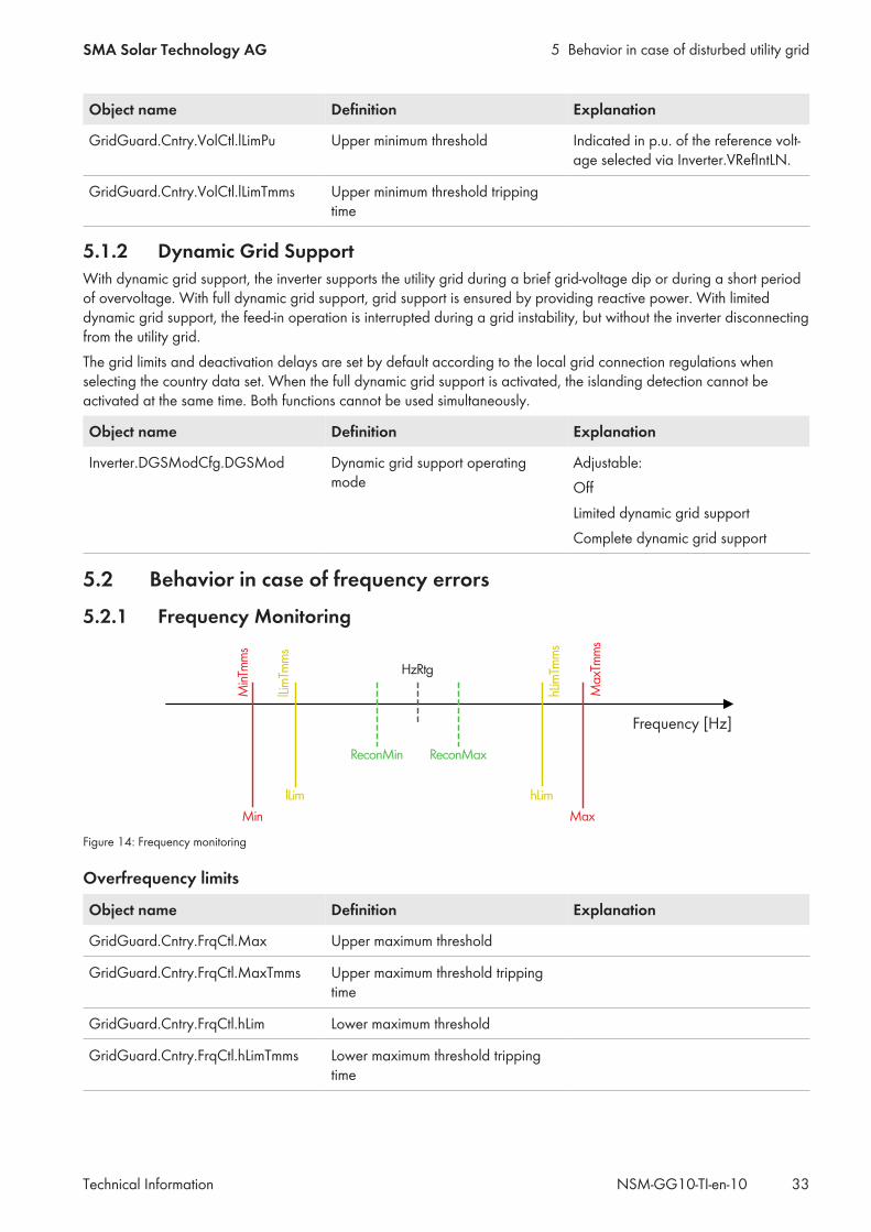
5.2.1 Frequency Monitoring
Max
Max
Tmm
s
hLim
hLim
Tmm
s
Min
Min
Tmm
s
lLim
Tmm
s
lLim
HzRtg
ReconMin ReconMax
Frequency [Hz]
Figure 14: Frequency monitoring
Overfrequency limits
Object name Definition Explanation
GridGuard.Cntry.FrqCtl.Max Upper maximum threshold
GridGuard.Cntry.FrqCtl.MaxTmms Upper maximum threshold trippingtime
GridGuard.Cntry.FrqCtl.hLim Lower maximum threshold
GridGuard.Cntry.FrqCtl.hLimTmms Lower maximum threshold trippingtime
5 Behavior in case of disturbed utility grid SMA Solar Technology AG
Technical InformationNSM-GG10-TI-en-1034
Underfrequency limits
Object name Definition Explanation
GridGuard.Cntry.FrqCtl.lLim Upper minimum threshold
GridGuard.Cntry.FrqCtl.lLimTmms Upper minimum threshold trippingtime
GridGuard.Cntry.FrqCtl.Min Lower minimum threshold
GridGuard.Cntry.FrqCtl.MinTmms Lower minimum threshold trippingtime
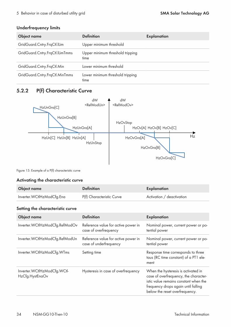
5.2.2 P(f) Characteristic Curve
HzUnStop
Hz
HzUnGra[C]
HzUnGra[B]
HzUnGra[A]
dW<RefModOv>
dW<RefModUn>
HzOvStop
HzOv[C]HzOv[A] HzOv[B]
HzOvGra[A]
HzOvGra[B]
HzOvGra[C]
HzUn[C] HzUn[B] HzUn[A]
Figure 15: Example of a P(f) characteristic curve
Activating the characteristic curve
Object name Definition Explanation
Inverter.WCtlHzModCfg.Ena P(f) Characteristic Curve Activation / deactivation
Setting the characteristic curve
Object name Definition Explanation
Inverter.WCtlHzModCfg.RefModOv Reference value for active power incase of overfrequency
Nominal power, current power or po-tential power
Inverter.WCtlHzModCfg.RefModUn Reference value for active power incase of underfrequency
Nominal power, current power or po-tential power
Inverter.WCtlHzModCfg.WTms Setting time Response time corresponds to threetaus (RC time constant) of a PT1 ele-ment
Inverter.WCtlHzModCfg.WCtl-HzCfg.HystEnaOv
Hysteresis in case of overfrequency When the hysteresis is activated incase of overfrequency, the character-istic value remains constant when thefrequency drops again until fallingbelow the reset overfrequency.
5 Behavior in case of disturbed utility gridSMA Solar Technology AG
Technical Information 35NSM-GG10-TI-en-10
Object name Definition Explanation
Inverter.WCtlHzModCfg.WCtl-HzCfg.HystEnaUn
Hysteresis in case of underfrequency When the hysteresis is activated incase of underfrequency, the charac-teristic value remains constant whenthe frequency increases again untilthe reset underfrequency is ex-ceeded.
Inverter.WCtlHzModCfg.WCtl-HzCfg.HzOv
Buckling overfrequencies
Inverter.WCtlHzModCfg.WCtl-HzCfg.HzOvGra
Active power change per Hz in caseof overfrequency
Indicated in % of the maximum, cur-rent or potential active power (de-pending on the setting of In-verter.WCtlHzModCfg.RefModOv).
Inverter.WCtlHzModCfg.WCtl-HzCfg.HzOvStop
Reset overfrequency Upon falling below this frequency,the characteristic curve is deactivatedand the transition to normal opera-tion is started.
Inverter.WCtlHzModCfg.WCtl-HzCfg.HzUn
Buckling underfrequency
Inverter.WCtlHzModCfg.WCtl-HzCfg.HzUnGra
Active power change per Hz in caseof underfrequency
Indicated in % of the maximum, cur-rent or potential active power (de-pending on the setting of In-verter.WCtlHzModCfg.RefModUn).
Inverter.WCtlHzModCfg.WCtl-HzCfg.HzUnStop
Reset underfrequency When this frequency is exceeded, thecharacteristic curve is deactivatedand the transition to normal opera-tion started.
Behavior when activating / deactivating the characteristic curve
Object name Definition Explanation
Inverter.WCtlHzModCfg.WCtl-HzCfg.WCtlTmms
Tripping delay Initial delay of the power change af-ter exceeding the first buckling fre-quency.
Inverter.WCtlHzModCfg.WCtl-HzCfg.HzStopWGraTms
Power-down time Waiting time until the transition tonormal operation is started.
Inverter.WCtlHzModCfg.WCtl-HzCfg.HzStopWGra
Active power change rate after faultend
The reference value is WMax.
5.3 Islanding DetectionThe islanding detection function detects the formation of unwanted electrical islands and disconnects the inverter fromthe utility grid. Unwanted islanding can occur when at the time of utility grid failure, the load in the shut-down sub-gridis roughly equivalent to the current feed-in power of the PV system or battery storage system. With active islandingdetection, the inverter continuously checks the stability of the utility grid. There are two modes for this. One mode
5 Behavior in case of disturbed utility grid SMA Solar Technology AG
Technical InformationNSM-GG10-TI-en-1036
monitors the frequency and the other detects unbalanced loads between the line conductors. The unbalance detectionis only supported by three-phase inverters. If the utility grid is intact, the modes for islanding detection have no impacton the utility grid and the inverter continues to feed in. Only if an unwanted electrical island has formed will the inverterdisconnect from the utility grid.By selecting the country data set, the islanding detection is deactivated or activated and adjusted according to thecountry standard. When the islanding detection is activated, the complete dynamic grid support cannot be activated atthe same time. Both functions cannot be used simultaneously.
Object name Definition Explanation
GridGuard.Cntry.Aid.HzMon.Stt Islanding detection, status of fre-quency monitor
Adjustable:On / OnOff / Off
GridGuard.Cntry.Aid.AsymDet.Stt Islanding detection, status of the un-balanced detection
Adjustable:On / OnOff / Off


www.SMA-Solar.com