Embed Size (px)
Citation preview
10
Technical Information – Relays
Relay Classification
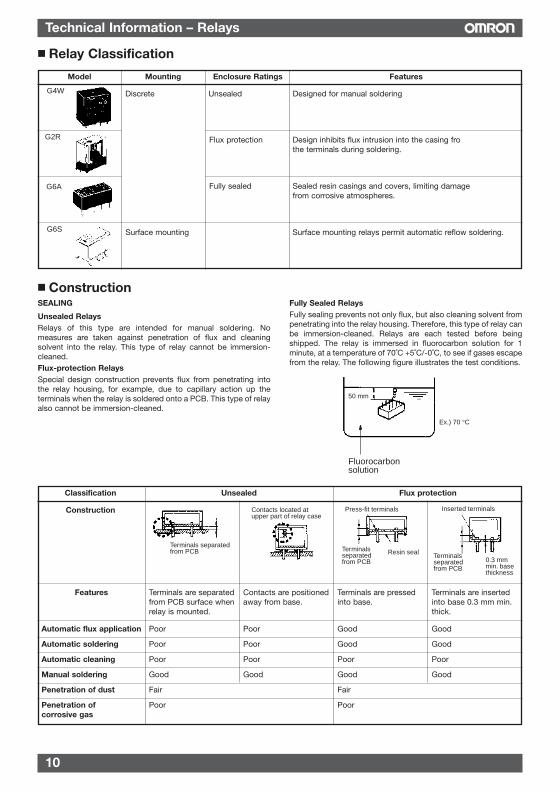
SEALING
Unsealed RelaysRelays of this type are intended for manual soldering. Nomeasures are taken against penetration of flux and cleaningsolvent into the relay. This type of relay cannot be immersion-cleaned.Flux-protection RelaysSpecial design construction prevents flux from penetrating intothe relay housing, for example, due to capillary action up theterminals when the relay is soldered onto a PCB. This type of relayalso cannot be immersion-cleaned.
Fully Sealed RelaysFully sealing prevents not only flux, but also cleaning solvent frompenetrating into the relay housing. Therefore, this type of relay canbe immersion-cleaned. Relays are each tested before beingshipped. The relay is immersed in fluorocarbon solution for 1minute, at a temperature of 70˚C +5˚C/-0˚C, to see if gases escapefrom the relay. The following figure illustrates the test conditions.
Construction
Relay
Fluorocarbon solution
50 mm
Ex.) 70 °C
Model Mounting Enclosure Ratings Features
Discrete Unsealed Designed for manual solderingG4W
G2R
G6A
G6S
Flux protection Design inhibits flux intrusion into the casing frothe terminals during soldering.
Fully sealed Sealed resin casings and covers, limiting damagefrom corrosive atmospheres.
Surface mounting Surface mounting relays permit automatic reflow soldering.
Classification Unsealed Flux protection
Construction
Automatic flux application Poor Poor Good Good
Automatic soldering Poor Poor Good Good
Automatic cleaning Poor Poor Poor Poor
Manual soldering Good Good Good Good
Penetration of dust Fair Fair
Penetration of Poor Poorcorrosive gas
Terminals separated from PCB
Contacts located at upper part of relay case
Terminals separated from PCB
Press-fit terminals
Resin seal Terminals separated from PCB
0.3 mm min. base thickness
Inserted terminals
Terminals are separatedfrom PCB surface whenrelay is mounted.
Features Contacts are positionedaway from base.
Terminals are pressedinto base.
Terminals are insertedinto base 0.3 mm min.thick.
11
Technical Information – Relays
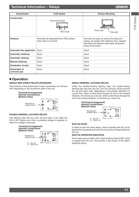
SINGLE-SIDE STABLE RELAYS (STANDARD)
The contacts of this simple type of relay momentarily turn ON andOFF, depending on the excitement state of the coil.
DOUBLE-WINDING, LATCHING RELAYS
This latching relay has two coils: set and reset. It can retain theON or OFF states even when a pulsating voltage is supplied, orwhen the voltage is removed.
SINGLE-WINDING, LATCHING RELAYS
Unlike the double-winding latching relay, the single-windinglatching relay has only one coil. This coil, however, serves as boththe set and reset coils, depending on the polarity (direction) ofcurrent flow. When current flows through the coil in the forwarddirection, it functions as a set coil; when current flows through thecoil in the reverse direction, it functions as a reset coil.
BUILT-IN DIODE
A diode is built into some relays, wired in parallel with the coil toabsorb the counterelectromotive force (counter emf) generated bythe coil.BUILT-IN OPERATION INDICATOR
Some relays are provided with a light-emitting diode (LED), wiredin parallel with the coil. This permits a fast–check of the relay’soperating status.
Operation
Classification Fully Sealed Surface Mounting
Construction
Automatic flux application Good Good
Automatic soldering Good Good
Automatic cleaning Good Good
Manual soldering Good Good
Penetration of dust Good Good
Penetration of Good Goodcorrosive gas
Resin sealGlue padResin seal
Press-fit terminals
Terminals are separated from PCB surfacewhen relay is mounted.
Features Terminal and base, as well as the base andcasing, are sealed with adhesive; the L-shapedterminals and adhesive pads allow temporaryfixing to the board.
Terminal Arrangement/ Internal Connections (Bottom View)
Mounting orientation mark
Terminal Arrangement/ Internal Connections (Bottom View)
Mounting orientation mark
S: Set coilR: Reset coil
S R
Terminal Arrangement/ Internal Connections (Bottom View)
Mounting orientation mark
S: Set coilR: Reset coil
S R
PC
B R
elay
s
12
Technical Information – Relays
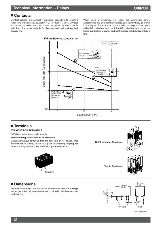
Contact ratings are generally indicated according to resistiveloads and inductive loads (cosø = 0.4 or L/R = 7 ms). Contactshape and material are also shown to guide the customer inselection of a model suitable for the intended load and requiredservice life.
When used at extremely low loads, the failure rate differsaccording to the contact material and contact method, as shownin the figure. For example, in comparing a single contact pointwith a bifurcated contact point, the bifurcated contact model hashigher parallel redundancy and will therefore exhibit a lower failurerate.
Contacts
Failure Rate vs. Load Current
Failu
re r
ate
(10
/o
pera
tion)
−6
Gold-platedsingle contract
Gold-plated bifurcated contact
Gold-clad bifurcated crossbar contact
10 VDC (constant)
Load current (mA)
STRAIGHT PCB TERMINALS
PCB terminals are normally straight.Self-clinching (S-shaped) PCB TerminalsSome relays have terminals that are bent into an “S” shape. Thissecures the PCB relay to the PCB prior to soldering, helping theterminals stay in their holes and keeping the relay level.
Terminals
For miniature relays, the maximum dimensions and the averagevalues ( ) marked with an asterisk are provided to aid the customerin designing.
Dimensions
Terminal
Quick-connect Terminals
Plug-in Terminals
16 max. (15.9)*
8 max. (7.9)* 0.3
3.5
0.60.4 x 0.4
9.9 max. (9.8)*
7.62
0.25
*Average value
13
Technical Information – Relays
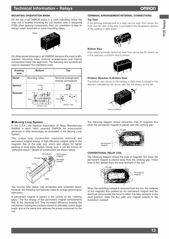
MOUNTING ORIENTATION MARK
On the top of all OMRON relays is a mark indicating where therelay coil is located. Knowing the coil location aids in designingPCBs when spacing components. Also, pin orientation is easy todiscern when automatic or hand-mounting relays.
On dimensional drawings in all OMRON literature this mark is left-oriented. Mounting holes, terminal arrangements, and internalconnections follow this alignment. The following two symbols areused to represent the orientation mark.
TERMINAL ARRANGEMENT/INTERNAL CONNECTIONS
Top ViewIf the terminal arrangement of a relay can be seen from above thePCB, the top view of the relay is provided in the Dimensions sectionof the catalog or data sheet.
Bottom ViewIf the relay’s terminals cannot be seen from above the PC board, asin this example, a bottom view is shown.
Rotation Direction to Bottom ViewThe bottom view shown in the catalog or data sheet is rotated in thedirection indicated by the arrow, with the coil always on the left.
Moving Loop SystemIn the U.S.A., the National Association of Relay Manufactures(NARM) in April 1984, awarded OMRON for monumentaladvances in relay technology, as embodied in the Moving LoopSystem.
This unique relay construction maximizes electrical andpermanent magnet energy. A high-efficiency magnet adds to themagnetic flux of the relay coil, which also allows for tighterpacking of relay parts. Relays having such a coil are known as“polarized relays.” Details of construction are shown below.
The moving loop design has similarities with polarized relays;however, the following two features make for a large performancedistinction.
A permanent magnet is placed in the vicinity of the “workinggaps.” The flux energy of this permanent magnet complementsthat of the electrical coil. This increased efficiency enables themechanism holding the contacts closed to ultimately switch largerloads, and at the same time reduces the power consumed by thecoil.
The following diagram shows concentric lines of magnetic fluxwhen the permanent magnet is placed near the working gap.
CONVENTIONAL RELAY COIL
The following diagram shows the lines of magnetic flux when thepermanent magnet is placed away from the working gap. Theselines of flux detract from the total strength of the coil.
When the switching voltage is removed from the coil, the collapseof the magnetic flux created by the permanent magnet and theelectrical coil provides the force to return the relay contacts to thereset position. Note the flux path and magnet polarity in theillustration overleaf.
Mark
Armature Permanent magnet
Air gap
Core
Movable contact
Yoke
Core
Permanent magnet
Air gap
Permanent magnet
Air gap
Axis of rotation
Drawing Bottom Topview
Detail Mounting holes Terminal arrangement/ internal connections
Symbol
Example
Mark
(Bottom view)
Mark
(Bottom view)
PC
B R
elay
sP
CB
Rel
ays
14
Technical Information – Relays
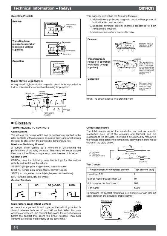
Release
Transition fromrelease to operation(operating voltagesupplied)
Operation
Permanent magnet
Repulsion
Movement
Attraction
Release
Transition fromrelease to operation(operating voltagesupplied)
Operation
Released status is maintained by permanent magnet.
N
S
RepulsionAttraction
The armature seesaws due to the attraction and repulsion torque exerted on the armature by the coil voltage and the permanent magnet.
N
S
N
S
Energized status is maintained by the coil voltage and permanent magnet.
NS
N
S
Super Moving Loop SystemA very small high-sensitivity magnetic circuit is incorporated tofurther minimize the conventional moving loop system.
This magnetic circuit has the following features:1. High-efficiency polarized magnetic circuit utilizes power of
both attraction and repulsion.2. Balanced armature system improves resistance to both
vibration and impacts.3. Ideal mechanism for a low-profile relay.
Armature
Permanent magnet
Core
Coil
Axis of rotation
N
S
Note: The above applies to a latching relay.
TERMS RELATED TO CONTACTS
Carry CurrentThe value of the current which can be continuously applied to therelay contacts without opening or closing them, and which allowsthe relay to stay within the permissible temperature rise.Maximum Switching CurrentA current which serves as a reference in determining theperformance of the relay contacts. This value will never exceedthe current flow. When using a relay, do not exceed this value.Contact FormOMRON uses the following relay terminology for the variouspolarity and switch configurations.SPST-NO (Single-pole, single-throw, normally open)SPST-NC (Single-pole, single-throw, normally close)SPDT (or changeover contact) (single-pole, double-throw)DPDT (Double-pole, double–throw)Contact Symbols
NO NC DT (NO/NC) MBB
Make-before-break (MBB) ContactA contact arrangement in which part of the switching section isshared between both an NO and NC contact. When the relayoperates or releases, the contact that closes the circuit operatesbefore the contact that opens the circuit releases. Thus bothcontacts are closed momentarily at the same time.
Contact ResistanceThe total resistance of the conductor, as well as specificresistivities such as of the armature and terminal, and theresistance of the contacts. This value is determined by measuringthe voltage drop across the contacts by applying test currents asshown in the table below.
Test Current
Rated current or switching current Test current (mA)
Less than 0.01 1
0.01 or higher but less than 0.1 10
0.1 or higher but less than 1 100
1 or higher 1,000
To measure the contact resistance, a milliohmmeter can also beused, although the accuracy drops slightly.
Glossary
A: AmmeterV V lt t
Contact sample
Power source
(DC or AC)
R
A: AmmeterV: VoltmeterR: Variable resistor
MilliohmmeterRelay
COMProbe
NC
Operating Principle
15
Technical Information – Relays
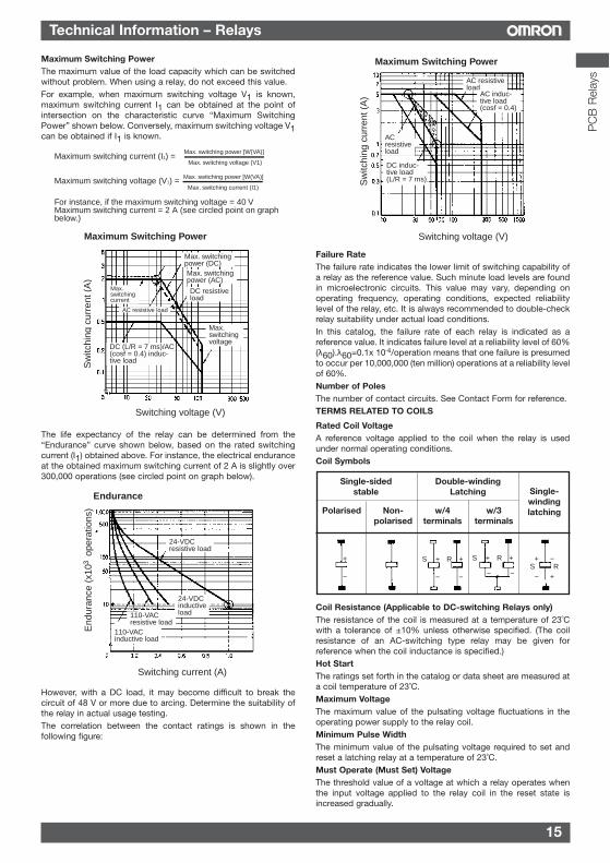
Maximum Switching PowerThe maximum value of the load capacity which can be switchedwithout problem. When using a relay, do not exceed this value.For example, when maximum switching voltage V1 is known,maximum switching current I1 can be obtained at the point ofintersection on the characteristic curve “Maximum SwitchingPower” shown below. Conversely, maximum switching voltage V1can be obtained if I1 is known.
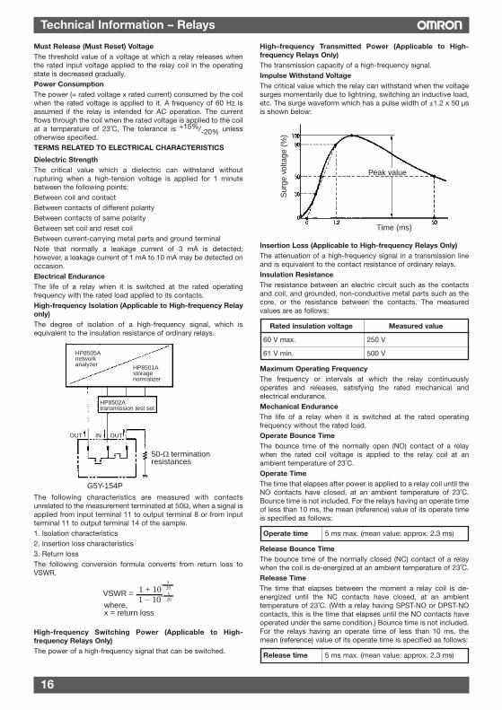
The life expectancy of the relay can be determined from the“Endurance” curve shown below, based on the rated switchingcurrent (I1) obtained above. For instance, the electrical enduranceat the obtained maximum switching current of 2 A is slightly over300,000 operations (see circled point on graph below).
However, with a DC load, it may become difficult to break thecircuit of 48 V or more due to arcing. Determine the suitability ofthe relay in actual usage testing.The correlation between the contact ratings is shown in thefollowing figure:
Failure RateThe failure rate indicates the lower limit of switching capability ofa relay as the reference value. Such minute load levels are foundin microelectronic circuits. This value may vary, depending onoperating frequency, operating conditions, expected reliabilitylevel of the relay, etc. It is always recommended to double-checkrelay suitability under actual load conditions. In this catalog, the failure rate of each relay is indicated as areference value. It indicates failure level at a reliability level of 60%(λ60).λ60=0.1x 10⁻⁶/operation means that one failure is presumedto occur per 10,000,000 (ten million) operations at a reliability levelof 60%.Number of PolesThe number of contact circuits. See Contact Form for reference.TERMS RELATED TO COILS
Rated Coil VoltageA reference voltage applied to the coil when the relay is usedunder normal operating conditions.Coil Symbols
Coil Resistance (Applicable to DC-switching Relays only)The resistance of the coil is measured at a temperature of 23˚Cwith a tolerance of ±10% unless otherwise specified. (The coilresistance of an AC-switching type relay may be given forreference when the coil inductance is specified.)Hot StartThe ratings set forth in the catalog or data sheet are measured ata coil temperature of 23˚C.Maximum VoltageThe maximum value of the pulsating voltage fluctuations in theoperating power supply to the relay coil.Minimum Pulse WidthThe minimum value of the pulsating voltage required to set andreset a latching relay at a temperature of 23˚C.Must Operate (Must Set) VoltageThe threshold value of a voltage at which a relay operates whenthe input voltage applied to the relay coil in the reset state isincreased gradually.
Single-sided Double-windingstable Latching
Polarised Non- w/4 w/3polarised terminals terminals
Maximum switching current (I1) =
Maximum switching voltage (V1) =
For instance, if the maximum switching voltage = 40 VMaximum switching current = 2 A (see circled point on graph below.)
Max. switching power [W(VA)]
Max. switching voltage (V1)
Max. switching power [W(VA)]
Max. switching current (I1)
Maximum Switching Power
Switching voltage (V)
Sw
itchi
ng c
urre
nt (
A)
AC resistive load
Max. switching voltage
DC resistive load
Max. switching power (DC)Max. switching power (AC)
DC (L/R = 7 ms)/AC (cosf = 0.4) induc-tive load
Max. switching current
Maximum Switching Power
Switching voltage (V)
Sw
itchi
ng c
urre
nt (
A)
AC resistive load
AC induc-tive load (cosf = 0.4)
ACresistive load
DC induc-tive load (L/R = 7 ms)
Endurance
Switching current (A)
End
uran
ce (
x10
ope
ratio
ns)
3
24-VDCresistive load
24-VDCinductive load
110-VACinductive load
110-VACresistive load
Single-windinglatching
+
−
+
−
+
−
S R +
−
+
−
S R +
− +
−S R
PC
B R
elay
s
16
Technical Information – Relays
Must Release (Must Reset) VoltageThe threshold value of a voltage at which a relay releases whenthe rated input voltage applied to the relay coil in the operatingstate is decreased gradually.Power ConsumptionThe power (= rated voltage x rated current) consumed by the coilwhen the rated voltage is applied to it. A frequency of 60 Hz isassumed if the relay is intended for AC operation. The currentflows through the coil when the rated voltage is applied to the coilat a temperature of 23˚C. The tolerance is +15%/-20% unlessotherwise specified.TERMS RELATED TO ELECTRICAL CHARACTERISTICS
Dielectric StrengthThe critical value which a dielectric can withstand withoutrupturing when a high-tension voltage is applied for 1 minutebetween the following points:Between coil and contactBetween contacts of different polarityBetween contacts of same polarityBetween set coil and reset coilBetween current-carrying metal parts and ground terminalNote that normally a leakage current of 3 mA is detected;however, a leakage current of 1 mA to 10 mA may be detected onoccasion.Electrical EnduranceThe life of a relay when it is switched at the rated operatingfrequency with the rated load applied to its contacts.High-frequency Isolation (Applicable to High-frequency Relayonly)The degree of isolation of a high-frequency signal, which isequivalent to the insulation resistance of ordinary relays.
The following characteristics are measured with contactsunrelated to the measurement terminated at 50Ω, when a signal isapplied from input terminal 11 to output terminal 8 or from inputterminal 11 to output terminal 14 of the sample.1. Isolation characteristics2. Insertion loss characteristics3. Return lossThe following conversion formula converts from return loss toVSWR.
High-frequency Switching Power (Applicable to High-frequency Relays Only)The power of a high-frequency signal that can be switched.
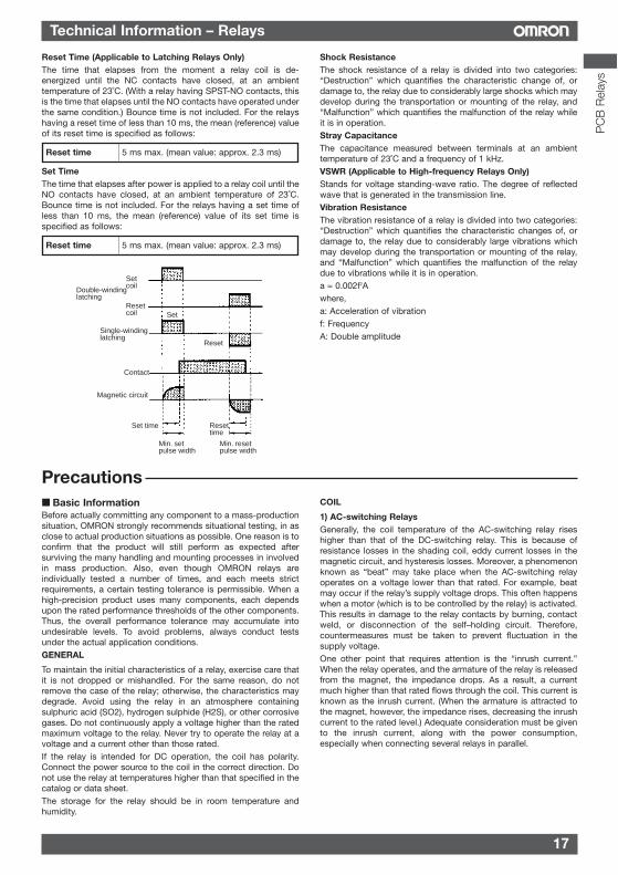
High–frequency Transmitted Power (Applicable to High-frequency Relays Only)The transmission capacity of a high-frequency signal.Impulse Withstand VoltageThe critical value which the relay can withstand when the voltagesurges momentarily due to lightning, switching an inductive load,etc. The surge waveform which has a pulse width of ±1.2 x 50 µsis shown below:
Insertion Loss (Applicable to High-frequency Relays Only)The attenuation of a high-frequency signal in a transmission lineand is equivalent to the contact resistance of ordinary relays.Insulation ResistanceThe resistance between an electric circuit such as the contactsand coil, and grounded, non-conductive metal parts such as thecore, or the resistance between the contacts. The measuredvalues are as follows:
Rated insulation voltage Measured value
60 V max. 250 V
61 V min. 500 V
Maximum Operating FrequencyThe frequency or intervals at which the relay continuouslyoperates and releases, satisfying the rated mechanical andelectrical endurance.Mechanical EnduranceThe life of a relay when it is switched at the rated operatingfrequency without the rated load.Operate Bounce TimeThe bounce time of the normally open (NO) contact of a relaywhen the rated coil voltage is applied to the relay coil at anambient temperature of 23˚C.Operate TimeThe time that elapses after power is applied to a relay coil until theNO contacts have closed, at an ambient temperature of 23˚C.Bounce time is not included. For the relays having an operate timeof less than 10 ms, the mean (reference) value of its operate timeis specified as follows:
Operate time 5 ms max. (mean value: approx. 2.3 ms)
Release Bounce TimeThe bounce time of the normally closed (NC) contact of a relaywhen the coil is de-energized at an ambient temperature of 23˚C.Release TimeThe time that elapses between the moment a relay coil is de-energized until the NC contacts have closed, at an ambienttemperature of 23˚C. (With a relay having SPST-NO or DPST-NOcontacts, this is the time that elapses until the NO contacts haveoperated under the same condition.) Bounce time is not included.For the relays having an operate time of less than 10 ms, themean (reference) value of its operate time is specified as follows:
Release time 5 ms max. (mean value: approx. 2.3 ms)
50-Ω termination resistances
G5Y-154P
HP8505Anetwork analyzer HP8501A
storage normalizer
HP8502Atransmission test set
OUT IN OUT
where,x = return loss
1 − 10VSWR =
−1 + 10 20
x
−20x
Time (ms)
Sur
ge v
olta
ge (
%)
Peak value
17
Technical Information – Relays
Precautions
Reset Time (Applicable to Latching Relays Only)The time that elapses from the moment a relay coil is de-energized until the NC contacts have closed, at an ambienttemperature of 23˚C. (With a relay having SPST-NO contacts, thisis the time that elapses until the NO contacts have operated underthe same condition.) Bounce time is not included. For the relayshaving a reset time of less than 10 ms, the mean (reference) valueof its reset time is specified as follows:
Reset time 5 ms max. (mean value: approx. 2.3 ms)
Set TimeThe time that elapses after power is applied to a relay coil until theNO contacts have closed, at an ambient temperature of 23˚C.Bounce time is not included. For the relays having a set time ofless than 10 ms, the mean (reference) value of its set time isspecified as follows:
Reset time 5 ms max. (mean value: approx. 2.3 ms)
Shock ResistanceThe shock resistance of a relay is divided into two categories:“Destruction” which quantifies the characteristic change of, ordamage to, the relay due to considerably large shocks which maydevelop during the transportation or mounting of the relay, and“Malfunction” which quantifies the malfunction of the relay whileit is in operation.Stray CapacitanceThe capacitance measured between terminals at an ambienttemperature of 23˚C and a frequency of 1 kHz.VSWR (Applicable to High-frequency Relays Only)Stands for voltage standing-wave ratio. The degree of reflectedwave that is generated in the transmission line.Vibration ResistanceThe vibration resistance of a relay is divided into two categories:“Destruction” which quantifies the characteristic changes of, ordamage to, the relay due to considerably large vibrations whichmay develop during the transportation or mounting of the relay,and “Malfunction” which quantifies the malfunction of the relaydue to vibrations while it is in operation.a = 0.002f2Awhere,a: Acceleration of vibrationf: FrequencyA: Double amplitude
Basic InformationBefore actually committing any component to a mass-productionsituation, OMRON strongly recommends situational testing, in asclose to actual production situations as possible. One reason is toconfirm that the product will still perform as expected aftersurviving the many handling and mounting processes in involvedin mass production. Also, even though OMRON relays areindividually tested a number of times, and each meets strictrequirements, a certain testing tolerance is permissible. When ahigh-precision product uses many components, each dependsupon the rated performance thresholds of the other components.Thus, the overall performance tolerance may accumulate intoundesirable levels. To avoid problems, always conduct testsunder the actual application conditions.GENERAL
To maintain the initial characteristics of a relay, exercise care thatit is not dropped or mishandled. For the same reason, do notremove the case of the relay; otherwise, the characteristics maydegrade. Avoid using the relay in an atmosphere containingsulphuric acid (SO2), hydrogen sulphide (H2S), or other corrosivegases. Do not continuously apply a voltage higher than the ratedmaximum voltage to the relay. Never try to operate the relay at avoltage and a current other than those rated.If the relay is intended for DC operation, the coil has polarity.Connect the power source to the coil in the correct direction. Donot use the relay at temperatures higher than that specified in thecatalog or data sheet.The storage for the relay should be in room temperature andhumidity.
COIL
1) AC-switching RelaysGenerally, the coil temperature of the AC-switching relay riseshigher than that of the DC-switching relay. This is because ofresistance losses in the shading coil, eddy current losses in themagnetic circuit, and hysteresis losses. Moreover, a phenomenonknown as “beat” may take place when the AC-switching relayoperates on a voltage lower than that rated. For example, beatmay occur if the relay’s supply voltage drops. This often happenswhen a motor (which is to be controlled by the relay) is activated.This results in damage to the relay contacts by burning, contactweld, or disconnection of the self–holding circuit. Therefore,countermeasures must be taken to prevent fluctuation in thesupply voltage.One other point that requires attention is the “inrush current.”When the relay operates, and the armature of the relay is releasedfrom the magnet, the impedance drops. As a result, a currentmuch higher than that rated flows through the coil. This current isknown as the inrush current. (When the armature is attracted tothe magnet, however, the impedance rises, decreasing the inrushcurrent to the rated level.) Adequate consideration must be givento the inrush current, along with the power consumption,especially when connecting several relays in parallel.
Double-winding latching
Single-winding latching
Contact
Magnetic circuit
Min. set pulse width
Min. reset pulse width
Set coil
Set
Reset
Set time Reset time
Reset coil
PC
B R
elay
s
18
Technical Information – Relays
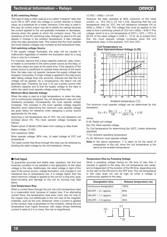
2) DC-switching RelaysThis type of relay is often used as a so-called “marginal” relay thatturns ON or OFF when the voltage or current reaches a criticalvalue, as a substitute for a meter. However, if the relay is used inthis way, its control output may fail to satisfy the ratings becausethe current applied to the coil gradually increases or decreases,slowing down the speed at which the contacts move. The coilresistance of the DC-switching relay changes by about 0.4% perdegree C change in the ambient temperature. It also changeswhen the relay generates heat. This means that the must operateand must release voltages may increase as the temperature rises.Coil switching voltage SourceIf the supply voltage fluctuates, the relay will be caused tomalfunction regardless of whether the fluctuation lasts for a longtime or only for a moment. For example, assume that a large-capacity solenoid, relay, motor,or heater is connected to the same power source as the relay, orthat many relays are used at the same time. If the capacity of thepower source is insufficient to operate these devices at the sametime, the relay may not operate, because the supply voltage hasdropped. Conversely, if a high voltage is applied to the relay (evenafter taking voltage drop into account), chances are that the fullvoltage will be applied. As a consequence, the relay’s coil willgenerate heat. Therefore, be sure 1) to use a power source withsufficient capacity and 2) that the supply voltage to the relay iswithin the rated must operate voltage range of the relay.Minimum Must Operate VoltageWhen the relay is used at a high temperature, or when the relaycoil is continuously energized, the coil temperature rises and coilresistance increases. Consequently, the must operate voltageincreases. This increase in the must operate voltage requiresattention when determining the minimum must operate voltageare given below for reference when designing a power sourceappropriate for the relay.Assuming a coil temperature rise of 10˚C, the coil resistance willincrease about 4%. The must operate voltage increases asfollows:Rated values of Model LZN2 taken from catalog or data sheetRated voltage: 12 VDCCoil resistance: 500ΩMust operate voltage: 80% max. of rated voltage at 23˚C coiltemperatureThe rated current that flows through this relay can be obtained bydividing the rated voltage by the coil resistance. Hence,
12 VDC ÷ 500Ω = 24 mAHowever, the relay operates at 80% maximum of this ratedcurrent, i.e., 19.2 mA (= 24 mA x 0.8). Assuming that the coiltemperature rises by 10˚C, the coil resistance increases 4% to520Ω (= 500Ω x 1.04). The voltage that must be applied to therelay to flow a switching current of 19.2 mA x 520Ω = 9.98 V. Thisvoltage, which is at a coil temperature of 33˚C (= 23˚C + 10˚C), is83.2% of the rated voltage (= 9.98 V ÷ 12 V). As is evident fromthis, the must operate voltage increases when the coiltemperature rises, in this example, 10˚C from 23˚C.
The minimum must operate voltage can be determined by thisexpression.
where,E (V): Rated coil voltageEpv (%): Must operate voltageTa: Coil temperature for determining Epv (20˚C, unless otherwisespecified)T (˚C): Ambient operating temperatureET (V): Minimum must operate voltageNote: In the above expression, T is taken to be the result of
energization of the coil, when the coil temperature is thesame as the ambient temperature.
Coil Temperature vs.Must Operate/release Voltage (LZN)
Ambient temperature (°C)
Per
cent
age
agai
nst r
ated
val
ue (
%)
Must operate voltage
Must release voltage
Coil voltage: 24 VDCN = 10 (mean value)
ET > E x x ( + 1) [V]Epv + 5
100T - Ta
234.5 + Ta
Coil InputTo guarantee accurate and stable relay operation, the first andforemost condition to be satisfied is the application of the ratedvoltage to the relay. Additionally, the rated voltage in light of thetype of the power source, voltage fluctuation, and changes in coilresistance due to temperature rise. If a voltage higher than therated maximum voltage is applied to the coil for a long time, layershort-circuiting and damage to the coil by burning may takeplace.Coil Temperature RiseWhen a current flows through the coil, the coil’s temperature risesto a measurable level, because of copper loss. If an alternatingcurrent flows, the temperature rises even more, due not only tothe copper loss, but additionally to the iron loss of the magneticmaterials, such as the core. Moreover, when a current is appliedto the contact, heat is generated on the contacts, raising the coiltemperature even higher (however, with relays whose switchingcurrent is rated at 2 A or lower, this rise is insignificant).
Temperature Rise by Pulsating VoltageWhen a pulsating voltage having an ON time of less than 2minutes is applied to the relay, the coil temperature rise varies,and is independent of the duration of the ON time, depending onlyon the ratio of the ON time to the OFF time. The coil temperaturein this case does not rise as high as when a voltage iscontinuously applied to the relay.
Energization time Release temperature rise
Continuous energization 100%
ON:OFF = 3:1 approx. 80%
ON:OFF = 1:1 approx. 50%
ON:OFF = 1:3 approx. 35%
(V)1:1
(t)
19
Technical Information – Relays
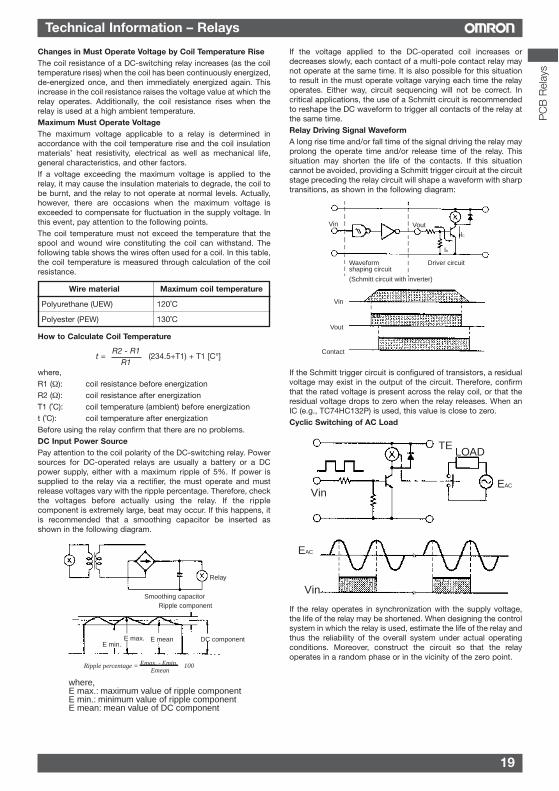
Changes in Must Operate Voltage by Coil Temperature RiseThe coil resistance of a DC-switching relay increases (as the coiltemperature rises) when the coil has been continuously energized,de-energized once, and then immediately energized again. Thisincrease in the coil resistance raises the voltage value at which therelay operates. Additionally, the coil resistance rises when therelay is used at a high ambient temperature.Maximum Must Operate VoltageThe maximum voltage applicable to a relay is determined inaccordance with the coil temperature rise and the coil insulationmaterials’ heat resistivity, electrical as well as mechanical life,general characteristics, and other factors.If a voltage exceeding the maximum voltage is applied to therelay, it may cause the insulation materials to degrade, the coil tobe burnt, and the relay to not operate at normal levels. Actually,however, there are occasions when the maximum voltage isexceeded to compensate for fluctuation in the supply voltage. Inthis event, pay attention to the following points.The coil temperature must not exceed the temperature that thespool and wound wire constituting the coil can withstand. Thefollowing table shows the wires often used for a coil. In this table,the coil temperature is measured through calculation of the coilresistance.
Wire material Maximum coil temperature
Polyurethane (UEW) 120˚C
Polyester (PEW) 130˚C
How to Calculate Coil Temperature
where,R1 (Ω): coil resistance before energizationR2 (Ω): coil resistance after energizationT1 (˚C): coil temperature (ambient) before energizationt (˚C): coil temperature after energizationBefore using the relay confirm that there are no problems.DC Input Power SourcePay attention to the coil polarity of the DC-switching relay. Powersources for DC-operated relays are usually a battery or a DCpower supply, either with a maximum ripple of 5%. If power issupplied to the relay via a rectifier, the must operate and mustrelease voltages vary with the ripple percentage. Therefore, checkthe voltages before actually using the relay. If the ripplecomponent is extremely large, beat may occur. If this happens, itis recommended that a smoothing capacitor be inserted asshown in the following diagram.
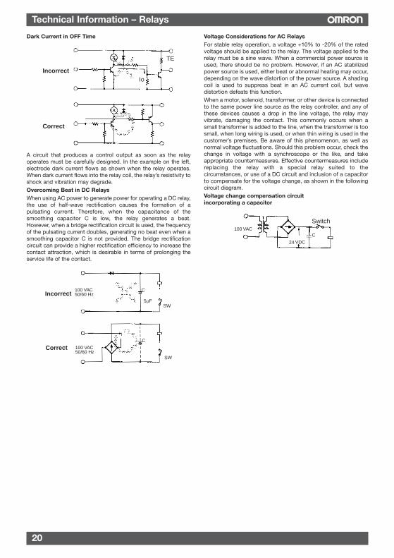
If the voltage applied to the DC-operated coil increases ordecreases slowly, each contact of a multi-pole contact relay maynot operate at the same time. It is also possible for this situationto result in the must operate voltage varying each time the relayoperates. Either way, circuit sequencing will not be correct. Incritical applications, the use of a Schmitt circuit is recommendedto reshape the DC waveform to trigger all contacts of the relay atthe same time.Relay Driving Signal WaveformA long rise time and/or fall time of the signal driving the relay mayprolong the operate time and/or release time of the relay. Thissituation may shorten the life of the contacts. If this situationcannot be avoided, providing a Schmitt trigger circuit at the circuitstage preceding the relay circuit will shape a waveform with sharptransitions, as shown in the following diagram:
If the Schmitt trigger circuit is configured of transistors, a residualvoltage may exist in the output of the circuit. Therefore, confirmthat the rated voltage is present across the relay coil, or that theresidual voltage drops to zero when the relay releases. When anIC (e.g., TC74HC132P) is used, this value is close to zero.Cyclic Switching of AC Load
If the relay operates in synchronization with the supply voltage,the life of the relay may be shortened. When designing the controlsystem in which the relay is used, estimate the life of the relay andthus the reliability of the overall system under actual operatingconditions. Moreover, construct the circuit so that the relayoperates in a random phase or in the vicinity of the zero point.
t = (234.5+T1) + T1 [C°]R2 - R1
R1
Smoothing capacitorRipple component
DC component
Relay
E min.E max. E mean
where,E max.: maximum value of ripple componentE min.: minimum value of ripple componentE mean: mean value of DC component
Ripple percentage = Emax. - Emin.Emean
100
Waveform shaping circuit
(Schmitt circuit with inverter)
Driver circuit
Vin Vout
Contact
Vin
Vout
IC
IB
TE
Vin
EAC
Vin
EAC
LOAD
PC
B R
elay
s
20
Technical Information – Relays
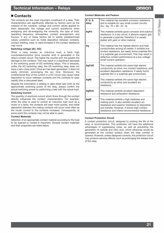
Dark Current in OFF Time
A circuit that produces a control output as soon as the relayoperates must be carefully designed. In the example on the left,electrode dark current flows as shown when the relay operates.When dark current flows into the relay coil, the relay’s resistivity toshock and vibration may degrade.Overcoming Beat in DC RelaysWhen using AC power to generate power for operating a DC relay,the use of half-wave rectification causes the formation of apulsating current. Therefore, when the capacitance of thesmoothing capacitor C is low, the relay generates a beat.However, when a bridge rectification circuit is used, the frequencyof the pulsating current doubles, generating no beat even when asmoothing capacitor C is not provided. The bridge rectificationcircuit can provide a higher rectification efficiency to increase thecontact attraction, which is desirable in terms of prolonging theservice life of the contact.
Voltage Considerations for AC RelaysFor stable relay operation, a voltage +10% to -20% of the ratedvoltage should be applied to the relay. The voltage applied to therelay must be a sine wave. When a commercial power source isused, there should be no problem. However, if an AC stabilizedpower source is used, either beat or abnormal heating may occur,depending on the wave distortion of the power source. A shadingcoil is used to suppress beat in an AC current coil, but wavedistortion defeats this function.When a motor, solenoid, transformer, or other device is connectedto the same power line source as the relay controller, and any ofthese devices causes a drop in the line voltage, the relay mayvibrate, damaging the contact. This commonly occurs when asmall transformer is added to the line, when the transformer is toosmall, when long wiring is used, or when thin wiring is used in thecustomer’s premises. Be aware of this phenomenon, as well asnormal voltage fluctuations. Should this problem occur, check thechange in voltage with a synchroscope or the like, and takeappropriate countermeasures. Effective countermeasures includereplacing the relay with a special relay suited to thecircumstances, or use of a DC circuit and inclusion of a capacitorto compensate for the voltage change, as shown in the followingcircuit diagram.Voltage change compensation circuitincorporating a capacitor
Incorrect
Correct
TE
Io
Incorrect
Correct
100 VAC 50/60 Hz
100 VAC 50/60 Hz
C
C
5µFSW
SW
Switch
24 VDC
100 VACC
21
Technical Information – Relays
ContactsThe contacts are the most important constituent of a relay. Theircharacteristics are significantly affected by factors such as thematerial of the contacts, voltage and current values applied tothem (especially, the voltage and current waveforms whenenergizing and de-energizing the contacts), the type of load,operating frequency, atmosphere, contact arrangement, andbounce. If any of these factors fail to satisfy predeterminedvalues, problems such as metal deposition between contacts,contact welding, wear, or rapid increase in the contact resistancemay occur.Switching voltage (AC, DC)When a relay breaks an inductive load, a fairly highcounterelectromotive force (counter emf) is generated in therelay’s contact circuit. The higher the counter emf, the greater thedamage to the contacts. This may result in a significant decreasein the switching power of DC-switching relays. This is because,unlike the AC-switching relay, the DC-switching relay does nothave a zero-cross point. Once arc has been generated, it does noteasily diminish, prolonging the arc time. Moreover, theunidirectional flow of the current in a DC circuit may cause metaldeposition to occur between contacts and the contacts to wearrapidly (this is discussed later).Despite the information a catalog or data sheet sets forth as theapproximate switching power of the relay, always confirm theactual switching power by performing a test with the actual load.Switching CurrentThe quantity of electrical current which flows through the contactdirectly influences the contact’ characteristics. For example,when the relay is used to control an inductive load such as amotor or a lamp, the contacts will wear more quickly, and metaldeposition between the mating contacts will occur more often asthe inrush current to the contacts increases. Consequently, atsome point the contacts may not be able to open. Contact MaterialsSelection of an appropriate contact material according to the loadto be opened or closed is important. Several contact materialsand their properties are listed below.
Contact Materials and Feature
Contact Protection CircuitA contact protection circuit, designed to prolong the life of therelay, is recommended. This protection will have the additionaladvantages of suppressing noise, as well as preventing thegeneration of carbide and nitric acid, which otherwise would begenerated at the contact surface when the relay contact isopened. However, unless designed correctly, the protection circuitmay produce adverse effects, such as prolonging the release timeof the relay.
P. G. S. This material has excellent corrosion resistanceAlloy and is suitable for very small current circuits.
(Au : Ag : Pt = 69 : 25 : 6)
AgPd This material exhibits good corrosion and sulphurresistance. In a dry circuit, it attracts organic gasto generate a polymer, therefore it is usuallyplated with gold or other material.
Ag This material has the highest electric and heatconductivities among all metals. It exhibits lowcontact resistance, but easily forms sulphide filmin a sulphide gas environment. This may result indefective contact performance at a low-voltagesmall-current operation.
AgCdO This material exhibits the same high electricconductivity as silver, low contact resistance, andexcellent deposition resistance. It easily formssulphide film in a sulphide gas environment.
AgNi This material exhibits the same high electricconductivity as silver and excellent arcresistance.
AgSnIn This material exhibits excellent depositionresistance and exhaustion resistance.
AgW This material exhibits a high hardness andmelting point. It also exhibits excellent arcresistance and superior resistance to depositionand transfer. However, it shows high contactresistance and inferior environmental resistance.
PC
B R
elay
s
22
Technical Information – Relays
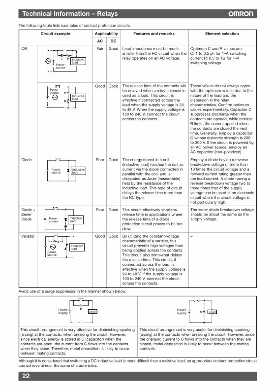
The following table lists examples of contact protection circuits.
Avoid use of a surge suppressor in the manner shown below.
Although it is considered that switching a DC inductive load is more difficult than a resistive load, an appropriate contact protection circuitcan achieve almost the same characteristics.
Circuit example Applicability Features and remarks Element selection
AC DC
CR Fair Good
Good Good
Diode Poor Good
Diode + Poor GoodZenerDiode
Varistor Good Good
Load impedance must be muchsmaller than the RC circuit when therelay operates on an AC voltage.
Optimum C and R values are:C: 1 to 0.5 µF for 1–A switchingcurrent R: 0.5 to 1Ω for 1–Vswitching voltage
These values do not always agreewith the optimum values due to thenature of the load and thedispersion in the relaycharacteristics. Confirm optimumvalues experimentally. Capacitor Csuppresses discharge when thecontacts are opened, while resistorR limits the current applied whenthe contacts are closed the nexttime. Generally, employ a capacitorC whose dielectric strength is 200to 300 V. If the circuit is powered byan AC power source, employ anAC capacitor (non–polarized).
The release time of the contacts willbe delayed when a relay solenoid isused as a load. This circuit iseffective if connected across theload when the supply voltage is 24to 48 V. When the supply voltage is100 to 240 V, connect the circuitacross the contacts.
The energy stored in a coil(inductive load) reaches the coil ascurrent via the diode connected inparallel with the coil, and isdissipated as Joule (measurable)heat by the resistance of theinductive load. This type of circuitdelays the release time more thanthe RC type.
This circuit effectively shortensrelease time in applications wherethe release time of a diodeprotection circuit proves to be tooslow.
By utilizing the constant-voltagecharacteristic of a varistor, thiscircuit prevents high voltages frombeing applied across the contacts.This circuit also somewhat delaysthe release time. This circuit, ifconnected across the load, iseffective when the supply voltage is24 to 48 V. If the supply voltage is100 to 240 V, connect the circuitacross the contacts.
–
The zener diode breakdown voltageshould be about the same as thesupply voltage.
Employ a diode having a reversebreakdown voltage of more than10 times the circuit voltage and aforward current rating greater thanthe load current. A diode having areverse breakdown voltage two tothree times that of the supplyvoltage can be used in an electroniccircuit where the circuit voltage isnot particularly high.
Power source
Inductive load
Inductive load
Power source
Inductive load
Power source
Inductive load
Power source
Inductive load
Power source
This circuit arrangement is very effective for diminishing sparking(arcing) at the contacts, when breaking the circuit. However,since electrical energy is stored in C (capacitor) when thecontacts are open, the current from C flows into the contactswhen they close. Therefore, metal deposition is likely to occurbetween mating contacts.
This circuit arrangement is very useful for diminishing sparking(arcing) at the contacts when breaking the circuit. However, sincethe charging current to C flows into the contacts when they areclosed, metal deposition is likely to occur between the matingcontacts.
Power supply Load Power
supply Load
23
Technical Information – Relays
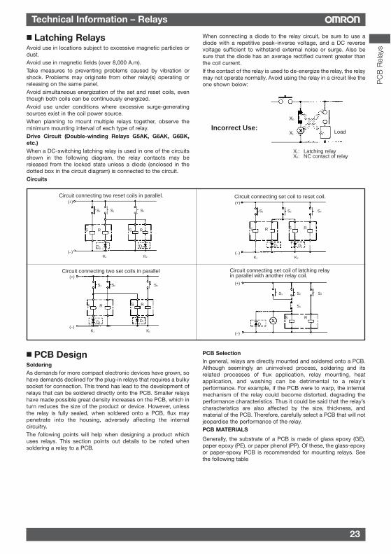
Latching RelaysAvoid use in locations subject to excessive magnetic particles ordust.Avoid use in magnetic fields (over 8,000 A.m).Take measures to preventing problems caused by vibration orshock. Problems may originate from other relay(s) operating orreleasing on the same panel.Avoid simultaneous energization of the set and reset coils, eventhough both coils can be continuously energized.Avoid use under conditions where excessive surge-generatingsources exist in the coil power source.When planning to mount multiple relays together, observe theminimum mounting interval of each type of relay.Drive Circuit (Double-winding Relays G5AK, G6AK, G6BK,etc.)When a DC-switching latching relay is used in one of the circuitsshown in the following diagram, the relay contacts may bereleased from the locked state unless a diode (enclosed in thedotted box in the circuit diagram) is connected to the circuit.Circuits
When connecting a diode to the relay circuit, be sure to use adiode with a repetitive peak–inverse voltage, and a DC reversevoltage sufficient to withstand external noise or surge. Also besure that the diode has an average rectified current greater thanthe coil current.If the contact of the relay is used to de-energize the relay, the relaymay not operate normally. Avoid using the relay in a circuit like theone shown below:
PCB DesignSolderingAs demands for more compact electronic devices have grown, sohave demands declined for the plug-in relays that requires a bulkysocket for connection. This trend has lead to the development ofrelays that can be soldered directly onto the PCB. Smaller relayshave made possible great density increases on the PCB, which inturn reduces the size of the product or device. However, unlessthe relay is fully sealed, when soldered onto a PCB, flux maypenetrate into the housing, adversely affecting the internalcircuitry.The following points will help when designing a product whichuses relays. This section points out details to be noted whensoldering a relay to a PCB.
PCB SelectionIn general, relays are directly mounted and soldered onto a PCB.Although seemingly an uninvolved process, soldering and itsrelated processes of flux application, relay mounting, heatapplication, and washing can be detrimental to a relay’sperformance. For example, if the PCB were to warp, the internalmechanism of the relay could become distorted, degrading theperformance characteristics. Thus it could be said that the relay’scharacteristics are also affected by the size, thickness, andmaterial of the PCB. Therefore, carefully select a PCB that will notjeopardise the performance of the relay.PCB MATERIALS
Generally, the substrate of a PCB is made of glass epoxy (GE),paper epoxy (PE), or paper phenol (PP). Of these, the glass-epoxyor paper-epoxy PCB is recommended for mounting relays. Seethe following table
XL: Latching relay Xb: NC contact of relay
LoadIncorrect Use:
Xb
XL
Circuit connecting two reset coils in parallel.(+)
(−)
S1 S2 S3
S R S R
D2D1
K1 K2
Circuit connecting two set coils in parallel(+)
(−)
S1 S2 S3
S R S R
D1
K1 K2
D2
Circuit connecting set coil to reset coil.(+)
(−)K1 K2
S1 S2 S3
S R S R
D2D1
Circuit connecting set coil of latching relay in parallel with another relay coil.
(+)
(−)
S1 S2 S4
S R
D
S3
PC
B R
elay
s
24
Technical Information – Relays
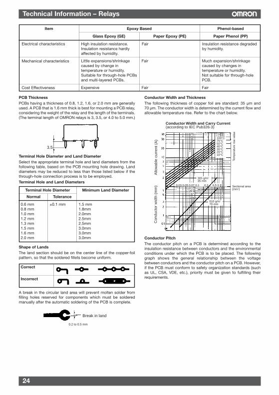
PCB ThicknessPCBs having a thickness of 0.8, 1.2, 1.6, or 2.0 mm are generallyused. A PCB that is 1.6 mm thick is best for mounting a PCB relay,considering the weight of the relay and the length of the terminals.(The terminal length of OMRON relays is 3, 3.5, or 4.0 to 5.0 mm.)
Terminal Hole Diameter and Land DiameterSelect the appropriate terminal hole and land diameters from thefollowing table, based on the PCB mounting hole drawing. Landdiameters may be reduced to less than those listed below if thethrough-hole connection process is to be employed.Terminal Hole and Land Diameters
Shape of LandsThe land section should be on the center line of the copper-foilpattern, so that the soldered fillets become uniform.
A break in the circular land area will prevent molten solder fromfilling holes reserved for components which must be solderedmanually after the automatic soldering of the PCB is complete.
Conductor Width and ThicknessThe following thickness of copper foil are standard: 35 µm and70 µm. The conductor width is determined by the current flow andallowable temperature rise. Refer to the chart below.
Conductor PitchThe conductor pitch on a PCB is determined according to theinsulation resistance between conductors and the environmentalconditions under which the PCB is to be placed. The followinggraph shows the general relationship between the voltagebetween conductors and the conductor pitch on a PCB. However,if the PCB must conform to safety organization standards (suchas UL, CSA, VDE, etc.), priority must be given to fulfilling theirrequirements.
3.5
Break in land
0.2 to 0.5 mm
Item Epoxy Based Phenol-based
Glass Epoxy (GE) Paper Epoxy (PE) Paper Phenol (PP)
Electrical characteristics
Mechanical characteristics
Cost Effectiveness
High insulation resistance.Insulation resistance hardlyaffected by humidity.
Little expansions/shrinkagecaused by change intemperature or humidity.Suitable for through-hole PCBsand multi-layered PCBs.
Fair Much expansion/shrinkagecaused by changes intemperature or humidity.Not suitable for through-holePCB.
Expensive Fair Fair
Fair Insulation resistance degradedby humidity.
Correct
Incorrect
Conductor Width and Carry Current(according to IEC Pub326-3)
Sectional area (mm )
Allo
wab
le c
urre
nt (
A)
Con
duct
or w
idth
(m
m)
Tem
pera
ture
ris
e va
lue
100°C75°C50°C40°C30°C20°C10°C
0.03 0.05 0.07 0.1 0.3 0.5 0.7
610 g/m 70 mm
305 g/m35 mm
2
2
2Terminal Hole Diameter Minimum Land Diameter
Normal Tolerance
0.6 mm ±0.1 mm 1.5 mm0.8 mm 1.8mm1.0 mm 2.0mm1.2 mm 2.5mm1.3 mm 2.5mm1.5 mm 3.0mm1.6 mm 3.0mm2.0 mm 3.0mm
25
Technical Information – Relays
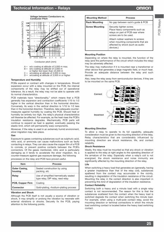
Voltage between Conductors vs. Conductor Pitch
Rat
ed v
olta
ge c
ondu
ctor
s (V
DC
)
Conductor pitch (mm)
A = w/o coating at altitude of 3,000 m max.B = w/o coating at altitude of 3,000 m
or higher but lower than 15,000 mC = w/coating at altitude of 3,000 m max.D = w/coating at altitude of 3,000 m or higher
C
A
DB
Temperature and HumidityPCBs expand or contract with changes in temperature. Shouldexpansion occur with a relay mounted on the PCB, the internalcomponents of the relay may be shifted out of operationaltolerance. As a result, the relay may not be able to operate withits normal characteristics.PCB materials have “directionality,” which means that a PCBgenerally has expansion and contraction coefficients 1/10 to 1/2higher in the vertical direction than in the horizontal direction.Conversely, its warp in the vertical direction is 1/10 to 1/2 lessthan in the horizontal direction. Therefore, take adequate counter-measures against humidity by coating the PCB. Should heat orhumidity be entirely too high, the relay’s physical characteristicswill likewise be affected. For example, as the heat rises the PCB’sinsulation resistance degrades. Mechanically, PCB parts willcontinue to expand as heat is applied, eventually passing theelastic limit, which will permanently warp components. Moreover, if the relay is used in an extremely humid environment,silver migration may take place.GasExposure to gases containing substances such as sulphuric acid,nitric acid, or ammonia can cause malfunctions such as faultycontacting in relays. They can also cause the copper film of a PCBto corrode, or prevent positive contacts between the PCB’sconnectors. Of the gases mentioned, nitric acid is particularlydamaging as it tends to accelerate the silver migration. As acounter-measure against gas exposure damage, the followingprocesses on the relay and PCB have proved useful.
Item Process
Outer Casing, Sealed construction by using housing packing, etc
Relay Use of simplified hermetically sealedtype relay, DIP relay, reed relay
PCB, Copper Firm Coating
Connector Gold-plating, rhodium-plating process
Vibration and ShockAlthough the PCB itself is not usually a source of vibration orshock, it may simplify or prolong the vibration by resonate withexternal vibrations or shocks. Securely fix the PCB, payingattention to the following points.
Mounting PositionDepending on where the relay is mounted, the function of therelay (and the performance of the circuit which includes the relay)may be adversely affected.The relay may malfunction if it is mounted near a transformer orother device that generates a large magnetic field, or much heat.Provide an adequate distance between the relay and suchdevices.Also, keep the relay away from semiconductor devices, if they areto be mounted on the same PCB.
Mounting DirectionTo allow a relay to operate to its full capability, adequateconsideration must be given to the mounting direction of the relay.Relay characteristics that are considerably influenced bymounting direction are shock resistance, life, and contactreliability.Shock ResistanceIdeally, the relay must be mounted so that any shock or vibrationis applied to the relay at right angles to the operating direction ofthe armature of the relay. Especially when a relay’s coil is notenergized, the shock resistance and noise immunity aresignificantly affected by the mounting direction of the relay.LifeWhen switching a heavy load that generates arc (generally, havinga greater impedance than that of the relay coil), substancesspattered from the contact may accumulate in the vicinity,resulting in degradation of the insulation resistance of the circuit.Mounting the relay in the correct direction is also important inpreventing this kind of degradation of the insulation resistance. Contact ReliabilitySwitching both a heavy and a minute load with a single relaycontact is not recommended. The reason for this is that thesubstances scattered from the contact when the heavy load isswitched degrade the contact when switching the minute load.For example, when using a multi-pole contact relay, avoid themounting direction or terminal connections in which the minuteload switching contact is located below the heavy load switchingcontact.
Correct
Incorrect
Mounting Method Process
Rack Mounting No gap between rack’s guide & PCB
Screw Mounting Securely tighten screw.Place heavy components such asrelays on part of PCB near wherescrews are to be used.
Attach rubber washers to screwswhen mounting components that areaffected by shock (such as audio devices.)
PC
B R
elay
s
26
Technical Information – Relays
Automatic Mounting of Relay on PCBTHOUGH-HOLE MOUNTING
The following tables list the processes required for mounting a relay onto a PCB and the points to be noted in each process.Process 1: PlacementDo not bend any terminal of the relay to use it as a self–clinching relay or the relay may malfunction.It is recommended to use magazine-packaged self–clinching relays for placement onto the PCB.Possibility of Automatic Placement
Process 2: Flux ApplicationTo apply flux to a flux protection or fully sealed relay, a sponge soaked with flux can be used. Place the relay in the holes drilled in thePCB and press the PCB (with the relay still mounted) firmly against the sponge. The flux will be pushed up the relay’s contact legs, andthrough the PCB holes. This method must never be applied with an unsealed relay because the flux will penetrate into the relay.The flux used with the sponge must be a non-corrosive resin-type flux.For the flux solvent, use an alcohol–based solvent, which tends to be less chemically reactive.Apply the flux sparingly and evenly to prevent penetration into the relay. When dipping the relay terminals into liquid flux, be sure to adjustthe flux level, so that the upper surface of the PCB is not flooded with flux.Possibility of Dipping Method
Process 3: TransportationWhen the PCB is transported, the relay mounted on the PCB may be lifted from the board surface due to vibration. This can be preventedif the relay mounted on the PCB has self-clinching terminals.
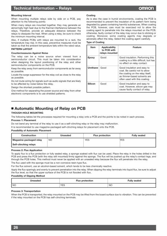
Mounting IntervalWhen mounting multiple relays side by side on a PCB, payattention to the following points:When many relays are mounted together, they may generate anabnormally high heat due to the thermal interference between therelays. Therefore, provide an adequate distance between therelays to dissipate the heat. When using a relay, be sure to checkthe minimum mounting interval.Also, if multiple PCBs with relays are mounted to a rack, thetemperature may rise. In this case, preventive measures must betaken so that the ambient temperature falls within the rated value.PATTERN LAYOUT
Countermeasures Against NoiseThe relay can be a noise source when viewed from asemiconductor circuit. This must be taken into considerationwhen designing the layout positioning of the relay and othersemiconductor components on the PCB.Keep the relay away from semiconductor components as far awayas possible.Locate the surge suppressor for the relay coil as close to the relayas possible.Do not route wiring for signals such as audio signals that are likelyto be affected by noise below the relay.Design the shortest possible pattern.One method for separating the power source and relay from otherelectronic components is to use shielded patterns.
CoatingAs is also the case in humid environments, coating the PCB isrecommended to prevent the insulation of its pattern form beingdegraded by gases containing harmful substances. When coatingthe PCB, however, care must be exercised not to allow thecoating agent to penetrate into the relays mounted on the PCB;otherwise, faulty contact of the relay may occur due to sticking orcoating. Moreover, some coating agents may degrade oradversely affect the relay. Select the coating agent carefully.Type of Coating
Unsealed Flux protection Fully sealed
NO YES NO
Construction Unsealed Flux protection Fully sealed
Magazine-packaged relay NO YES YES
Self-clinching relays
Item Applicability Featureto PCB with
relays mounted
Epoxy Good Good insulation. Performing this coating is a little difficult, but hasno effect on relay contact.
Urethane Good Good insulation and easy tocoat. Be careful not to allowthe coating on the relay itself,as thinner-based solvents areoften used with this coating.
Silicon Good Good insulation and easy tocoat. However, silicon gas maycause faulty contact of relay.
27
Technical Information – Relays
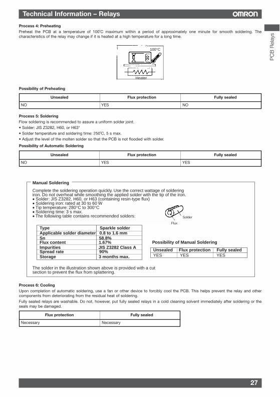
Process 4: PreheatingPreheat the PCB at a temperature of 100˚C maximum within a period of approximately one minute for smooth soldering. Thecharacteristics of the relay may change if it is heated at a high temperature for a long time.
Possibility of Preheating
Process 5: SolderingFlow soldering is recommended to assure a uniform solder joint.• Solder: JIS Z3282, H60, or H63*• Solder temperature and soldering time: 250˚C, 5 s max.• Adjust the level of the molten solder so that the PCB is not flooded with solder.
Possibility of Automatic Soldering
Process 6: CoolingUpon completion of automatic soldering, use a fan or other device to forcibly cool the PCB. This helps prevent the relay and othercomponents from deteriorating from the residual heat of soldering.Fully sealed relays are washable. Do not, however, put fully sealed relays in a cold cleaning solvent immediately after soldering or theseals may be damaged.
Complete the soldering operation quickly. Use the correct wattage of soldering iron. Do not overheat while smoothing the applied solder with the tip of the iron.• Solder: JIS Z3282, H60, or H63 (containing resin-type flux)• Soldering iron: rated at 30 to 60 W• Tip temperature: 280°C to 300°C• Soldering time: 3 s max.• The following table contains recommended solders:
Type Sparkle solderApplicable solder diameter 0.8 to 1.6 mmSn 58.8%Flux content 1.67%Impurities JIS Z3282 Class A Spread rate 90%Storage 3 months max.
Solder
Flux
The solder in the illustration shown above is provided with a cut section to prevent the flux from splattering.
Possibility of Manual Soldering
Unsealed Flux protection Fully sealedYES YES YES
Manual Soldering
Unsealed Flux protection Fully sealed
NO YES NO
Flux protection Fully sealed
Necessary Necessary
Unsealed Flux protection Fully sealed
NO YES YES
100°C
Heater
PC
B R
elay
s
28
Technical Information – Relays
Note: 1. Consult your OMRON representative before using any other cleaning solvent. Do not use Freon-TMC-based, thinner-based, orgasoline-based cleaning solvents.
2. Worldwide efforts are being made at discontinuing the use of CFC-113-based (fluorochlorocarbon-based) and trichloroethylene-based cleaning solvents. The user is requested to refrain from using these cleaning solvents
3. It may be difficult to clean the space between the relay and PCB using hydrogen-based or alcohol-based cleaning solvent. It isrecommended the stand-off-type be used G6A- -ST when using hydrogen-based or alcohol-based cleaning solvents.
4. Ultrasonic cleaning may have an adverse effect on the performance of relays not specifically manufactured for ultrasoniccleaning. Please refer to the model number to determine if your relay is intended to be cleaned ultrasonically.
Process 8: CoatingDo not apply a coating agent to any flux-resistant relay or relay with a case because the coating agent will penetrate into the relay andthe contacts may be damaged.Some coating agents may damage the case of the relay. Be sure to use a proper coating agent.Do not fix the position of relay with resin or the characteristics of the relay will change.
Resin Fully Sealed
Epoxy YES
Urethane YES
Silicone NO
Fluorine YES
List of Cleaning Solvents
Chlorine-based Perochlene YesChlorosolderTrichloroethylene
Water-based Indusco YesHolys
Alcohol-based IPA YesEthanol
Others Thinner NoGasoline
Cleaning method Automatic cleaningUltrasonic cleaning (see note 4)
Solvent Fully Seated
Process 7: CleaningAvoid cleaning the soldered terminals whenever possible. When a resin-type flux is used, no cleaning is necessary. If cleaning cannot beavoided, exercise care in selecting an appropriate cleaning solvent.
Clensing Method
Unsealed Flux protection Fully sealed
Boiling cleaning and immersion cleaning are possible. Ultrasonic cleaningwill have an adverse effect on the performance of relays not specifically
manufactured for ultrasonic cleaning.When cleaning the G2R or any other relay, the ambient temperature must be
within the permissible ambient operating temperature range of the relay.
Boiling cleaning and immersioncleaning are not possible. Clean only
the back of the PCB with a brush.
29
Technical Information – Relays
PC
B R
elay
s
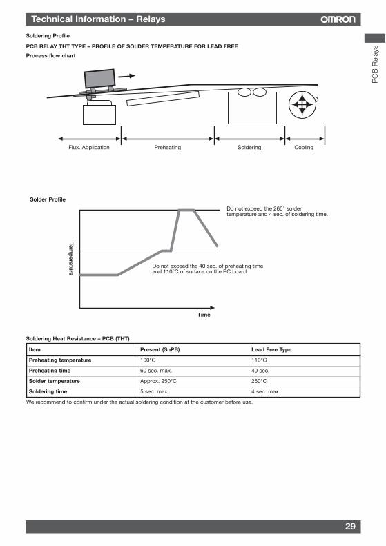
Soldering Profile
Do not exceed the 260° soldertemperature and 4 sec. of soldering time.
Do not exceed the 40 sec. of preheating timeand 110°C of surface on the PC board
Temp
eratureTime
Flux. Application Preheating Soldering Cooling
PCB RELAY THT TYPE – PROFILE OF SOLDER TEMPERATURE FOR LEAD FREE
Process flow chart
Solder Profile
Soldering Heat Resistance – PCB (THT)
Item Present (SnPB) Lead Free Type
Preheating temperature 100°C 110°C
Preheating time 60 sec. max. 40 sec.
Solder temperature Approx. 250°C 260°C
Soldering time 5 sec. max. 4 sec. max.
We recommend to confirm under the actual soldering condition at the customer before use.
30
Technical Information – Relays
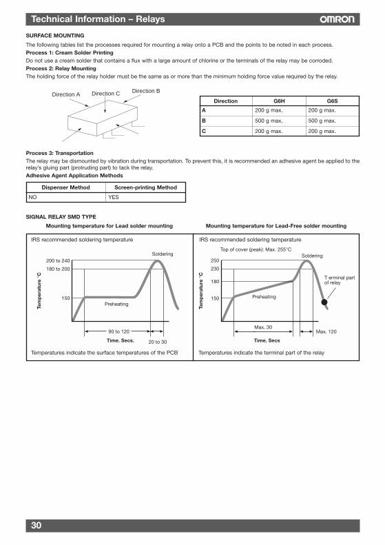
Mounting temperature for Lead solder mounting Mounting temperature for Lead-Free solder mounting
Tem
per
atur
e °C
Time. Secs.
Soldering
90 to 120
20 to 30
200 to 240
180 to 200
150Preheating
Soldering
Tem
per
atur
e °C
Time. Secs
Preheating
T erminal partof relay
Top of cover (peak): Max. 255°C
250
230
180
150
Max. 30Max. 120
Temperatures indicate the surface temperatures of the PCB Temperatures indicate the terminal part of the relay
IRS recommended soldering temperature IRS recommended soldering temperature
SIGNAL RELAY SMD TYPE
SURFACE MOUNTING
The following tables list the processes required for mounting a relay onto a PCB and the points to be noted in each process.Process 1: Cream Solder PrintingDo not use a cream solder that contains a flux with a large amount of chlorine or the terminals of the relay may be corroded.Process 2: Relay MountingThe holding force of the relay holder must be the same as or more than the minimum holding force value required by the relay.
Process 3: TransportationThe relay may be dismounted by vibration during transportation. To prevent this, it is recommended an adhesive agent be applied to therelay’s gluing part (protruding part) to tack the relay.Adhesive Agent Application Methods
Dispenser Method Screen-printing Method
NO YES
Direction ADirection BDirection C
Direction G6H G6S
A 200 g max. 200 g max.
B 500 g max. 500 g max.
C 200 g max. 200 g max.
31
Technical Information – Relays
PC
B R
elay
s
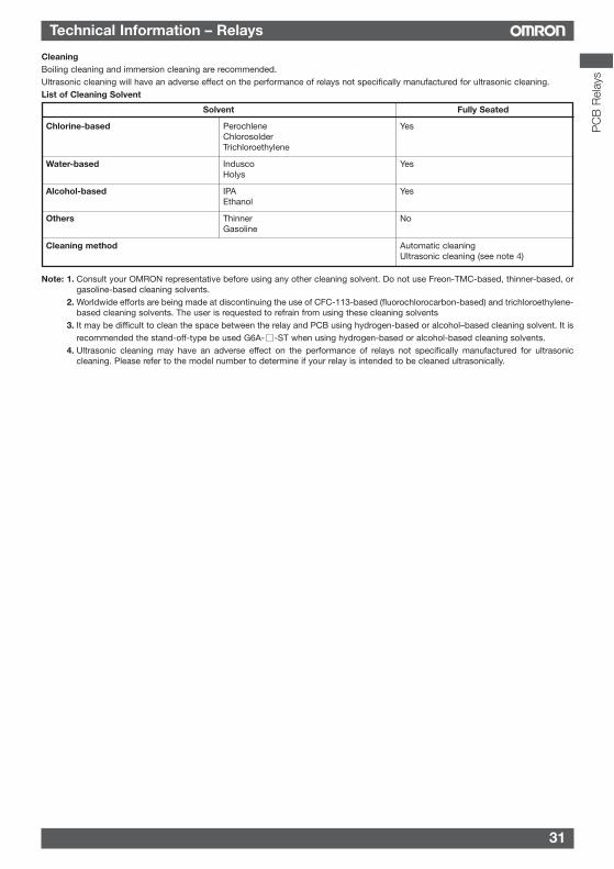
CleaningBoiling cleaning and immersion cleaning are recommended.Ultrasonic cleaning will have an adverse effect on the performance of relays not specifically manufactured for ultrasonic cleaning.List of Cleaning Solvent
Note: 1. Consult your OMRON representative before using any other cleaning solvent. Do not use Freon-TMC-based, thinner-based, orgasoline-based cleaning solvents.
2. Worldwide efforts are being made at discontinuing the use of CFC-113-based (fluorochlorocarbon-based) and trichloroethylene-based cleaning solvents. The user is requested to refrain from using these cleaning solvents
3. It may be difficult to clean the space between the relay and PCB using hydrogen-based or alcohol–based cleaning solvent. It isrecommended the stand-off-type be used G6A- -ST when using hydrogen-based or alcohol-based cleaning solvents.
4. Ultrasonic cleaning may have an adverse effect on the performance of relays not specifically manufactured for ultrasoniccleaning. Please refer to the model number to determine if your relay is intended to be cleaned ultrasonically.
Chlorine-based Perochlene YesChlorosolderTrichloroethylene
Water-based Indusco YesHolys
Alcohol-based IPA YesEthanol
Others Thinner NoGasoline
Cleaning method Automatic cleaningUltrasonic cleaning (see note 4)
Solvent Fully Seated
32
Selection Guide – Power Relays
Model
Features
Appearance
Dimensions(LxWxH)
Contact Contact FormRatings
Contact Type
Contact Material
Resistive Load
Max. SwitchingCurrent
Min. Permissibleload
Max. SwitchingPower
Max. SwitchingVoltage
Rated Voltage
PowerConsumption(Approx.)
Electrical(operations)
Mechanical(operations)
Between coiland contacts
Between contacts ofdifferent polarity
Between contacts ofsame polarity
Ambient temperature (operating)
Variations Single Side Stable
Single Winding Latching
Double Winding Latching
PCB Terminal
Plug-in Terminal
Quick Connect Terminal
Panel Mount
Fully sealed
Flux Protection
Approved Standards
Page
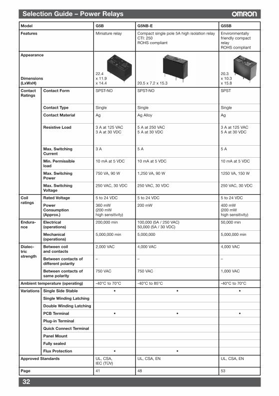
G5NB-E
Compact single pole 5A high isolation relayCTI: 250ROHS compliant
20.5 x 7.2 x 15.3
SPST-NO
Single
Ag Alloy
5 A at 250 VAC5 A at 30 VDC
5 A
10 mA at 5 VDC
1,250 VA, 90 W
250 VAC, 30 VDC
5 to 24 VDC
200 mW
100,000 (5A / 250 VAC)50,000 (5A / 30 VDC)
5,000,000
4,000 VAC
–
750 VAC
-40°C to 85°C
•
•
•
UL, CSA, EN
48
G5B
Miniature relay
22.4x 11.9x 14.4
SPST-NO
Single
Ag
3 A at 125 VAC3 A at 30 VDC
3 A
10 mA at 5 VDC
750 VA, 90 W
250 VAC, 30 VDC
5 to 24 VDC
360 mW(200 mWhigh sensitivity)
200,000 min
5,000,000 min
2,000 VAC
–
750 VAC
-40°C to 70°C
•
•
•
UL, CSA,IEC (TÜV)
41
G5SB
Environmentallyfriendly compactrelayROHS compliant
20.3x 10.3x 15.8
SPST
Single
Ag
3 A at 125 VAC5 A at 30 VDC
5 A
10 mA at 5 VDC
1250 VA, 150 W
250 VAC, 30 VDC
5 to 24 VDC
400 mW(200 mWhigh sensitivity)
50,000 min
5,000,000 min
4,000 VAC
–
1,000 VAC
-40°C to 70°C
•
•
UL, CSA, EN
53
Coilratings
Endura-nce
Dialec-tricstrength
33
Selection Guide – Power Relays
Model
Features
Appearance
Dimensions(LxWxH)
Contact Contact FormRatings
Contact Type
Contact Material
Resistive Load
Max. SwitchingCurrent
Min. Permissibleload
Max. SwitchingPower
Max. SwitchingVoltage
Rated Voltage
PowerConsumption(Approx.)
Electrical(operations)
Mechanical(operations)
Between coiland contacts
Between contacts ofdifferent polarity
Between contacts ofsame polarity
Ambient temperature (operating)
Variations Single Side Stable
Single Winding Latching
Double Winding Latching
PCB Terminal
Plug-in Terminal
Quick Connect Terminal
Panel Mount
Fully sealed
Flux Protection
Approved Standards
Page
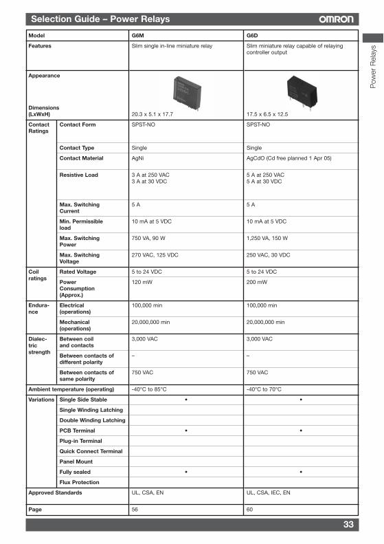
G6D
Slim miniature relay capable of relayingcontroller output
17.5 x 6.5 x 12.5
SPST-NO
Single
AgCdO (Cd free planned 1 Apr 05)
5 A at 250 VAC5 A at 30 VDC
5 A
10 mA at 5 VDC
1,250 VA, 150 W
250 VAC, 30 VDC
5 to 24 VDC
200 mW
100,000 min
20,000,000 min
3,000 VAC
–
750 VAC
-40°C to 70°C
•
•
•
UL, CSA, IEC, EN
60
Coilratings
Endura-nce
Dialec-tricstrength
G6M
Slim single in-line miniature relay
20.3 x 5.1 x 17.7
SPST-NO
Single
AgNi
3 A at 250 VAC3 A at 30 VDC
5 A
10 mA at 5 VDC
750 VA, 90 W
270 VAC, 125 VDC
5 to 24 VDC
120 mW
100,000 min
20,000,000 min
3,000 VAC
–
750 VAC
-40°C to 85°C
•
•
•
UL, CSA, EN
56
Pow
er R
elay
s
34
Selection Guide – Power Relays
Model
Features
Appearance
Dimensions(LxWxH)
Contact Contact FormRatings
Contact Type
Contact Material
Resistive Load
Max. SwitchingCurrent
Min. Permissibleload
Max. SwitchingPower
Max. SwitchingVoltage
Rated Voltage
PowerConsumption(Approx.)
Electrical(operations)
Mechanical(operations)
Between coiland contacts
Between contacts ofdifferent polarity
Between contacts ofsame polarity
Ambient temperature (operating)
Variations Single Side Stable
Single Winding Latching
Double Winding Latching
PCB Terminal
Plug-in Terminal
Quick Connect Terminal
Panel Mount
Fully sealed
Flux Protection
Approved Standards
Page
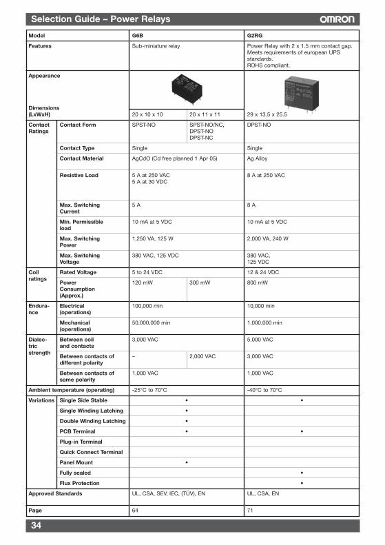
G2RG
Power Relay with 2 x 1.5 mm contact gap.Meets requirements of european UPSstandards.ROHS compliant.
29 x 13.5 x 25.5
DPST-NO
Single
Ag Alloy
8 A at 250 VAC
8 A
10 mA at 5 VDC
2,000 VA, 240 W
380 VAC,125 VDC
12 & 24 VDC
800 mW
10,000 min
1,000,000 min
5,000 VAC
3,000 VAC
1,000 VAC
-40°C to 70°C
•
•
•
•
UL, CSA, EN
71
Coilratings
Endura-nce
Dialec-tricstrength
G6B
Sub-miniature relay
20 x 10 x 10 20 x 11 x 11
SPST-NO SPST-NO/NC,DPST-NODPST-NC
Single
AgCdO (Cd free planned 1 Apr 05)
5 A at 250 VAC5 A at 30 VDC
5 A
10 mA at 5 VDC
1,250 VA, 125 W
380 VAC, 125 VDC
5 to 24 VDC
120 mW 300 mW
100,000 min
50,000,000 min
3,000 VAC
– 2,000 VAC
1,000 VAC
-25°C to 70°C
•
•
•
•
•
UL, CSA, SEV, IEC, (TÜV), EN
64
35
Selection Guide – Power Relays
Model
Features
Appearance
Dimensions (LxWxH)
Contact Contact FormRatings
Contact Type
Contact Material
Resistive Load
Max. SwitchingCurrent
Min. Permissibleload
Max. SwitchingPower
Max. SwitchingVoltage
Rated Voltage
PowerConsumption(Approx.)
Electrical(operations)
Mechanical(operations)
Between coiland contacts
Between contacts ofdifferent polarity
Between contacts ofsame polarity
Ambient temperature (operating)
Variations Single Side Stable
Single Winding Latching
Double Winding Latching
PCB Terminal
Plug-in Terminal
Quick Connect Terminal
Panel Mount
Fully sealed
Flux Protection
Approved Standards
Page
Coilratings
Endura-nce
Dialec-tricstrength
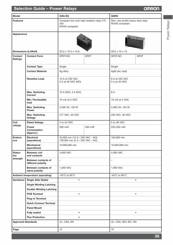
G6RN
Slim, low profile heavy duty relayROHS compliant
28.5 x 10 x 15
SPST-NO SPDT
Single
AgNi (Au clad)
8 A at 250 VAC5 A at 30 VDC
8 A
10 mA at 5 VDC
2,000 VA, 150 W
250 VAC, 30 VDC
5 to 48 VDC
220-250 mW
100,000 min
10,000,000 min
4,000 VAC
–
1,000 VAC
-40°C to 85°C
•
•
•
UL, CSA, SEV, IEC, EN
79
G5Q-EU
Compact low cost high isolation relay CTI:250ROHS compliant
20.3 x 10.3 x 15.8
SPST-NO SPDT
Single
Ag Alloy
10 A at 250 VAC5 A at 30 VDC (NO)
10 A (NO), 3 A (NC)
10 mA at 5 VDC
2,500 VA, 150 W
277 VAC, 30 VDC
5 to 24 VDC
200 mW 400 mW
25,000 min (10 A / 250 VAC – NO)100,000 min (3 A / 250 VAC – NC)
10,000,000 min
4,000 VAC
–
1,000 VAC
-40°C to 85°C
•
•
•
•
UL, CSA, EN
75
Pow
er R
elay
s
36
Selection Guide – Power Relays
Model
Features
Appearance
Dimensions (LxWxH)
Contact Contact FormRatings
Contact Type
Contact Material
Resistive Load
Max. SwitchingCurrent
Min. Permissibleload
Max. SwitchingPower
Max. SwitchingVoltage
Rated Voltage
PowerConsumption(Approx.)
Electrical(operations)
Mechanical(operations)
Between coiland contacts
Between contacts ofdifferent polarity
Between contacts ofsame polarity
Ambient temperature (operating)
Variations Single Side Stable
Single Winding Latching
Double Winding Latching
PCB Terminal
Plug-in Terminal
Quick Connect Terminal
Panel Mount
Fully sealed
Flux Protection
Approved Standards
Page
Coilratings
Endura-nce
Dialec-tricstrength
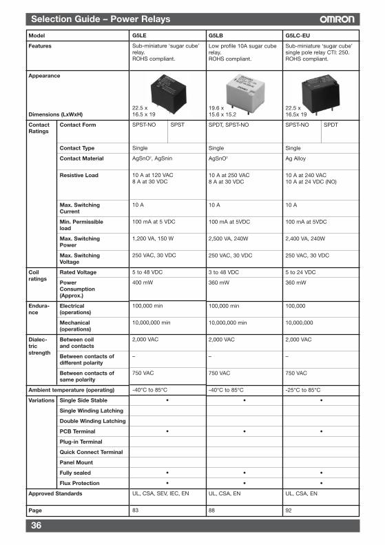
G5LC-EU
Sub-miniature ‘sugar cube’single pole relay CTI: 250.ROHS compliant.
22.5 x16.5x 19
SPST-NO SPDT
Single
Ag Alloy
10 A at 240 VAC10 A at 24 VDC (NO)
10 A
100 mA at 5VDC
2,400 VA, 240W
250 VAC, 30 VDC
5 to 24 VDC
360 mW
100,000
10,000,000
2,000 VAC
–
750 VAC
-25°C to 85°C
•
•
•
•
UL, CSA, EN
92
G5LB
Low profile 10A sugar cuberelay.ROHS compliant.
19.6 x15.6 x 15.2
SPDT, SPST-NO
Single
AgSnO2
10 A at 250 VAC8 A at 30 VDC
10 A
100 mA at 5VDC
2,500 VA, 240W
250 VAC, 30 VDC
3 to 48 VDC
360 mW
100,000 min
10,000,000 min
2,000 VAC
–
750 VAC
-40°C to 85°C
•
•
•
•
UL, CSA, EN
88
G5LE
Sub-miniature ‘sugar cube’relay.ROHS compliant.
22.5 x16.5 x 19
SPST-NO SPST
Single
AgSnO2, AgSnin
10 A at 120 VAC8 A at 30 VDC
10 A
100 mA at 5 VDC
1,200 VA, 150 W
250 VAC, 30 VDC
5 to 48 VDC
400 mW
100,000 min
10,000,000 min
2,000 VAC
–
750 VAC
-40°C to 85°C
•
•
•
•
UL, CSA, SEV, IEC, EN
83
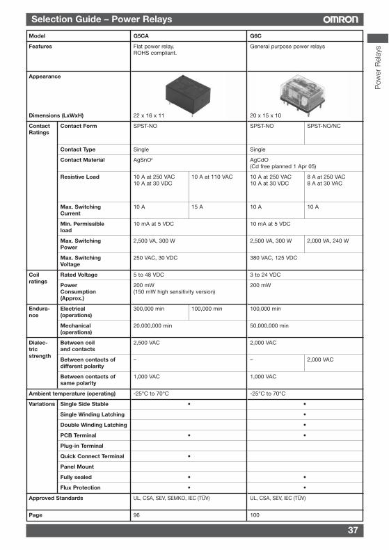
37
Selection Guide – Power Relays
Model
Features
Appearance
Dimensions (LxWxH)
Contact Contact FormRatings
Contact Type
Contact Material
Resistive Load
Max. SwitchingCurrent
Min. Permissibleload
Max. SwitchingPower
Max. SwitchingVoltage
Rated Voltage
PowerConsumption(Approx.)
Electrical(operations)
Mechanical(operations)
Between coiland contacts
Between contacts ofdifferent polarity
Between contacts ofsame polarity
Ambient temperature (operating)
Variations Single Side Stable
Single Winding Latching
Double Winding Latching
PCB Terminal
Plug-in Terminal
Quick Connect Terminal
Panel Mount
Fully sealed
Flux Protection
Approved Standards
Page
G6C
General purpose power relays
20 x 15 x 10
SPST-NO SPST-NO/NC
Single
AgCdO(Cd free planned 1 Apr 05)
10 A at 250 VAC 8 A at 250 VAC10 A at 30 VDC 8 A at 30 VAC
10 A 10 A
10 mA at 5 VDC
2,500 VA, 300 W 2,000 VA, 240 W
380 VAC, 125 VDC
3 to 24 VDC
200 mW
100,000 min
50,000,000 min
2,000 VAC
– 2,000 VAC
1,000 VAC
-25°C to 70°C
•
•
•
•
•
•
UL, CSA, SEV, IEC (TÜV)
100
Coilratings
Endura-nce
Dialec-tricstrength
G5CA
Flat power relay.ROHS compliant.
22 x 16 x 11
SPST-NO
Single
AgSnO2
10 A at 250 VAC 10 A at 110 VAC10 A at 30 VDC
10 A 15 A
10 mA at 5 VDC
2,500 VA, 300 W
250 VAC, 30 VDC
5 to 48 VDC
200 mW(150 mW high sensitivity version)
300,000 min 100,000 min
20,000,000 min
2,500 VAC
–
1,000 VAC
-25°C to 70°C
•
•
•
•
•
UL, CSA, SEV, SEMKO, IEC (TÜV)
96
Pow
er R
elay
s
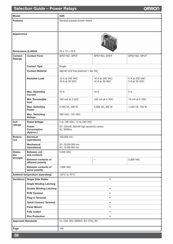
38
Selection Guide – Power Relays
Model
Features
Appearance
Dimensions (LxWxH)
Contact Contact FormRatings
Contact Type
Contact Material
Resistive Load
Max. SwitchingCurrent
Min. Permissibleload
Max. SwitchingPower
Max. SwitchingVoltage
Rated Voltage
PowerConsumption(Approx.)
Electrical(operations)
Mechanical(operations)
Between coiland contacts
Between contacts ofdifferent polarity
Between contacts ofsame polarity
Ambient temperature (operating)
Variations Single Side Stable
Single Winding Latching
Double Winding Latching
PCB Terminal
Plug-in Terminal
Quick Connect Terminal
Panel Mount
Fully sealed
Flux Protection
Approved Standards
Page
Coilratings
Endura-nce
Dialec-tricstrength
G2R
General pupose power relays
29 x 13 x 25.5
SPST-NO, SPDT SPST-NO, SPDT DPST-NO, DPDT
Single
AgCdO (Cd free planned 1 Apr 05)
10 A at 250 VAC 16 A at 250 VAC 5 A at 250 VAC10 A at 30 VDC 16 A at 30 VDC 5 A at 30 VDC
10 A 16 A 5 A
100 mA at 5 VDC 100 mA at 5 VDC 10 mA at 5 VDC
2,500 VA, 300 W 4,000 VA, 400 W 1,250 VA, 150 W
380 VAC, 125 VDC
5 to 100 VDC, 12 to 240 VAC
DC: 530mW; 360mW high sensitivity versionAC: 900Mva
100,000 min
DC: 20,000,000 minAC: 10,000,000 min
5,000 VAC
– – 3,000 VAC
1,000 VAC
-40°C to 70°C
•
•
•
•
•
•
•
•
UL, CSA, SEV, SEMKO, IEC (TÜV), EN
109
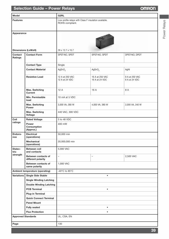
39
Selection Guide – Power Relays
Model
Features
Appearance
Dimensions (LxWxH)
Contact Contact FormRatings
Contact Type
Contact Material
Resistive Load
Max. SwitchingCurrent
Min. Permissibleload
Max. SwitchingPower
Max. SwitchingVoltage
Rated Voltage
PowerConsumption(Approx.)
Electrical(operations)
Mechanical(operations)
Between coiland contacts
Between contacts ofdifferent polarity
Between contacts ofsame polarity
Ambient temperature (operating)
Variations Single Side Stable
Single Winding Latching
Double Winding Latching
PCB Terminal
Plug-in Terminal
Quick Connect Terminal
Panel Mount
Fully sealed
Flux Protection
Approved Standards
Page
G2RL
Low profile relays with Class F insulation available.ROHS compliant.
29 x 12.7 x 15.7
SPST-NO, SPDT SPST-NO, SPDT DPST-NO, DPDT
Single
AgSnO2 AgSnO2 AgNi
12 A at 250 VAC 16 A at 250 VAC 8 A at 250 VAC12 A at 24 VDC 16 A at 24 VDC 8 A at 24 VDC
12 A 16 A 8 A
10 mA at 5 VDC
3,000 VA, 280 W 4,000 VA, 380 W 2,000 VA, 240 W
440 VAC, 300 VDC
5 to 48 VDC
400 mW
50,000 min
20,000,000 min
5,000 VAC
– – 2,500 VAC
1,000 VAC
-40°C to 85°C
•
•
•
•
UL, CSA, EN
130
Coilratings
Endura-nce
Dialec-tricstrength
Pow
er R
elay
s
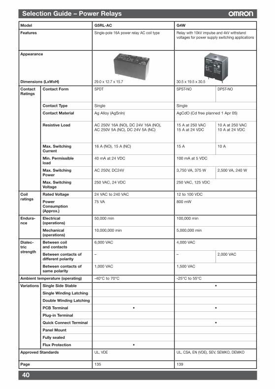
40
Selection Guide – Power Relays
Model
Features
Appearance
Dimensions (LxWxH)
Contact Contact FormRatings
Contact Type
Contact Material
Resistive Load
Max. SwitchingCurrent
Min. Permissibleload
Max. SwitchingPower
Max. SwitchingVoltage
Rated Voltage
PowerConsumption(Approx.)
Electrical(operations)
Mechanical(operations)
Between coiland contacts
Between contacts ofdifferent polarity
Between contacts ofsame polarity
Ambient temperature (operating)
Variations Single Side Stable
Single Winding Latching
Double Winding Latching
PCB Terminal
Plug-in Terminal
Quick Connect Terminal
Panel Mount
Fully sealed
Flux Protection
Approved Standards
Page
Coilratings
Endura-nce
Dialec-tricstrength
G4W
Relay with 10kV impulse and 4kV withstandvoltages for power supply switching applications
30.5 x 19.5 x 30.5
SPST-NO DPST-NO
Single
AgCdO (Cd free planned 1 Apr 05)
15 A at 250 VAC 10 A at 250 VAC15 A at 24 VDC 10 A at 24 VDC
15 A 10 A
100 mA at 5 VDC
3,750 VA, 375 W 2,500 VA, 240 W
250 VAC, 125 VDC
12 to 100 VDC
800 mW
100,000 min
5,000,000 min
4,000 VAC
– 2,000 VAC
1,500 VAC
-25°C to 55°C
•
•
•
UL, CSA, EN (VDE), SEV, SEMKO, DEMKO
139
G5RL-AC
Single-pole 16A power relay AC coil type
29.0 x 12.7 x 15.7
SPDT
Single
Ag Alloy (AgSnln)
AC 250V 16A (NO), DC 24V 16A (NO),AC 250V 5A (NC), DC 24V 5A (NC)
16 A (NO), 15 A (NC)
40 mA at 24 VDC
AC 250V, DC24V
250 VAC, 24 VDC
24 VAC to 240 VAC
75 VA
50,000 min
10,000,000 min
6,000 VAC
–
1,000 VAC
-40°C to 70°C
•
•
UL, VDE
135
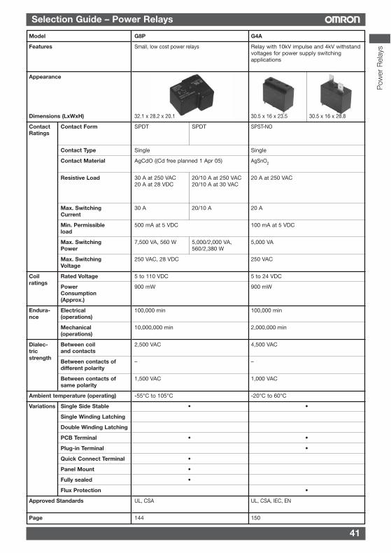
41
Selection Guide – Power Relays
G8P
Small, low cost power relays
32.1 x 28.2 x 20.1
SPDT SPDT
Single
AgCdO ((Cd free planned 1 Apr 05)
30 A at 250 VAC 20/10 A at 250 VAC20 A at 28 VDC 20/10 A at 30 VAC
30 A 20/10 A
500 mA at 5 VDC
7,500 VA, 560 W 5,000/2,000 VA,560/2,380 W
250 VAC, 28 VDC
5 to 110 VDC
900 mW
100,000 min
10,000,000 min
2,500 VAC
–
1,500 VAC
-55°C to 105°C
•
•
•
•
•
UL, CSA
144
Model
Features
Appearance
Dimensions (LxWxH)
Contact Contact FormRatings
Contact Type
Contact Material
Resistive Load
Max. SwitchingCurrent
Min. Permissibleload
Max. SwitchingPower
Max. SwitchingVoltage
Rated Voltage
PowerConsumption(Approx.)
Electrical(operations)
Mechanical(operations)
Between coiland contacts
Between contacts ofdifferent polarity
Between contacts ofsame polarity
Ambient temperature (operating)
Variations Single Side Stable
Single Winding Latching
Double Winding Latching
PCB Terminal
Plug-in Terminal
Quick Connect Terminal
Panel Mount
Fully sealed
Flux Protection
Approved Standards
Page
Coilratings
Endura-nce
Dialec-tricstrength
G4A
Relay with 10kV impulse and 4kV withstandvoltages for power supply switchingapplications
30.5 x 16 x 23.5 30.5 x 16 x 26.8
SPST-NO
Single
AgSnO2
20 A at 250 VAC
20 A
100 mA at 5 VDC
5,000 VA
250 VAC
5 to 24 VDC
900 mW
100,000 min
2,000,000 min
4,500 VAC
–
1,000 VAC
-20°C to 60°C
•
•
•
•
UL, CSA, IEC, EN
150
Pow
er R
elay
s
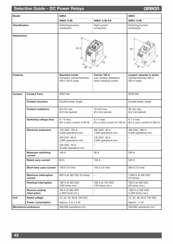
42
Selection Guide – DC Power Relays
Model
Classification
Appearance
Features
Contact Contact Form
Contact structure
Contact resistance
Switching voltage drop
Electrical endurance
Maximum switchingcurrent
Rated carry current
Short-time carry current
Maximum interruption current
Overload interruption
Reverse polarity interruption
Coil Rated voltage
Power consumption
Mechanical endurance
G9EA
G9EA-1(-B) G9EA-1(-B)-CA
Switching/current High-currentconduction conduction
Standard model Carries 100 ACompact, carries/switches Low contact resistance400 V, 60 A loads when carrying current
SPST-NO
Double-break, single
30 mΩ max. 10 mΩ max.(0.6 mΩ typical) (0.3 mΩ typical)
0.1 V max. 0.1 V max.(for a carry current of 60 A) (for a carry current of 100 A)
120 VDC, 100 A, 400 VDC, 30 A,3,000 operations min. 1,000 operations min.
400 VDC, 60 A, 120 VDC, 30 A,3,000 operations min. 2,500 operations min.
400 VDC, 30 A, –30,000 operations min.
100 A 30 A
60 A 100 A
100 A (10 min) 150 A (10 min)
600 A at 300 VDC (5 times) –
180 A at 400 VDC 100 A at 120 VDC(100 times min.) (150 times min.)
-60 A at 200 VDC –(1,000 times min.)
12, 24, 48, 60 & 100 VDC
Approx. 5 to 5.4 W
200,000 operations min.
G9EC
G9EC-1(-B)
Switching/currentconduction
Largest capacity in seriesCarries/switches 400 V,200 A loads
SPST-NO
Double-break, single
30 mΩ max.(0.2 mΩ typical)
0.1 V max.(for a carry current of 200 A)
400 VDC, 200 A,3,000 operations min.
–
–
200 A
200 A
300 A (15 min)
1,000 A at 400 VDC(10 times)
700 A at 400 VDC(40 times min.)
-200 A at 200 VDC(1,000 times min.)
12, 24, 48, 60 & 100 VDC
Approx. 11 W
200,000 operations min.
G9E
A-1-B
12VD
C
MAD
E IN JAPAN
CONTAC
T:
60A 4
00VD
C
Lot N
o. 1
362K
1-00
012(
-)
1(+)
73
36
67.2
G9E
C-1
-B
12VD
C
MAD
E IN JAPAN
CONTA
CT:
200A
400
VDC
Lot N
o. 1
362K
1-00
012(
-)
1(+)
98
44
86.7
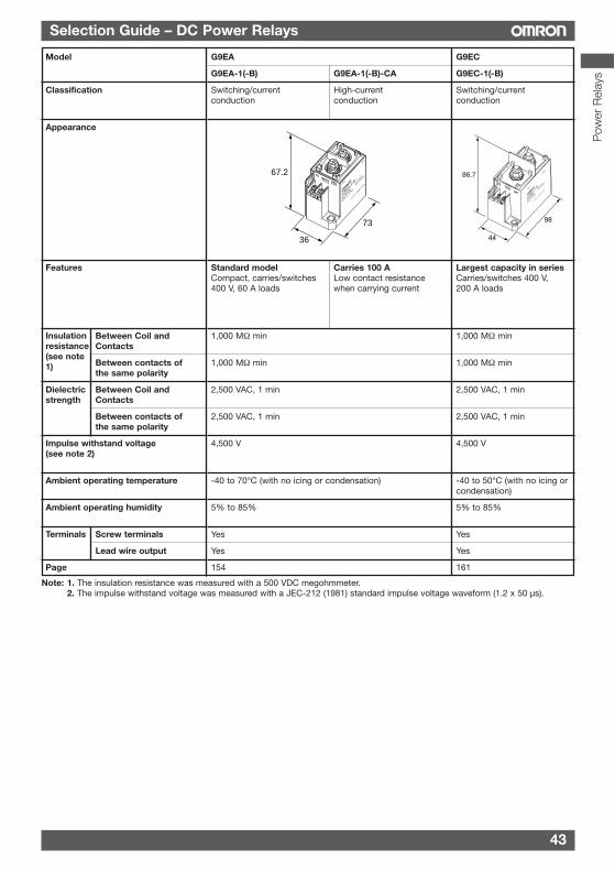
43
Selection Guide – DC Power Relays
Model
Classification
Appearance
Features
Between Coil andContacts
Between contacts ofthe same polarity
Between Coil andContacts
Between contacts ofthe same polarity
Impulse withstand voltage(see note 2)
Ambient operating temperature
Ambient operating humidity
Terminals Screw terminals
Lead wire output
Page
G9EA
G9EA-1(-B) G9EA-1(-B)-CA
Switching/current High-currentconduction conduction
Standard model Carries 100 ACompact, carries/switches Low contact resistance400 V, 60 A loads when carrying current
1,000 MΩ min
1,000 MΩ min
2,500 VAC, 1 min
2,500 VAC, 1 min
4,500 V
-40 to 70°C (with no icing or condensation)
5% to 85%
Yes
Yes
154
G9EC
G9EC-1(-B)
Switching/currentconduction
Largest capacity in seriesCarries/switches 400 V,200 A loads
1,000 MΩ min
1,000 MΩ min
2,500 VAC, 1 min
2,500 VAC, 1 min
4,500 V
-40 to 50°C (with no icing orcondensation)
5% to 85%
Yes
Yes
161
G9E
A-1-B
12VD
C
MAD
E IN JAPAN
CONTAC
T:
60A 4
00VD
C
Lot N
o. 1
362K
1-00
012(
-)
1(+)
73
36
67.2
G9E
C-1
-B
12VD
C
MAD
E IN JAPAN
CONTA
CT:
200A
400
VDC
Lot N
o. 1
362K
1-00
012(
-)
1(+)
98
44
86.7
Insulationresistance(see note1)
Dielectricstrength
Note: 1. The insulation resistance was measured with a 500 VDC megohmmeter.2. The impulse withstand voltage was measured with a JEC-212 (1981) standard impulse voltage waveform (1.2 x 50 µs).
Pow
er R
elay
s
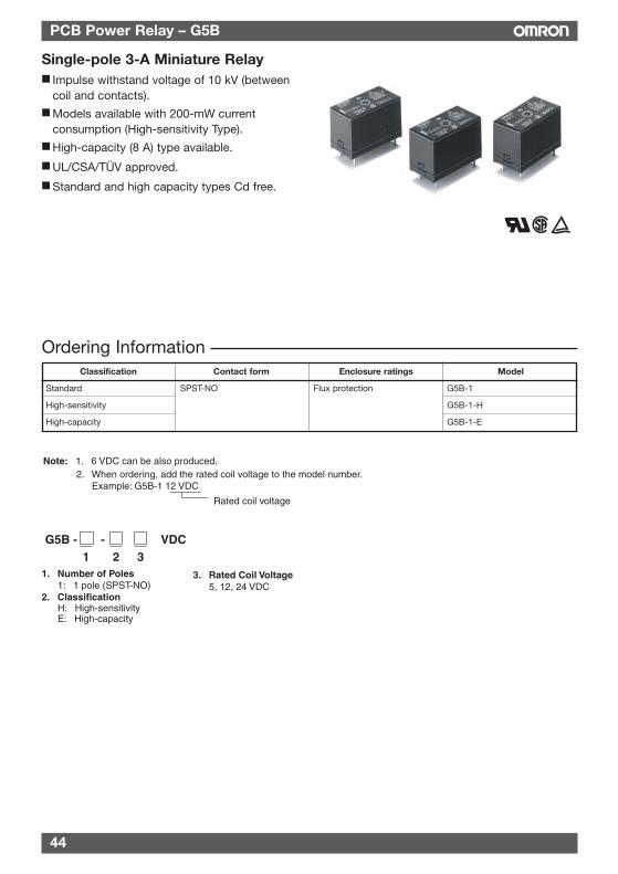
44
PCB Power Relay – G5B
Ordering Information
Single-pole 3-A Miniature Relay Impulse withstand voltage of 10 kV (between
coil and contacts). Models available with 200-mW current
consumption (High-sensitivity Type). High-capacity (8 A) type available.
UL/CSA/TÜV approved.
Standard and high capacity types Cd free.
Rated coil voltage
Note: 1. 6 VDC can be also produced. 2. When ordering, add the rated coil voltage to the model number.
Example: G5B-1 12 VDC
G5B - - VDC1 2 3
1. Number of Poles 1: 1 pole (SPST-NO)
2. Classification H: High-sensitivity E: High-capacity
3. Rated Coil Voltage 5, 12, 24 VDC
Classification Contact form Enclosure ratings Model
Standard SPST-NO Flux protection G5B-1
High-sensitivity G5B-1-H
High-capacity G5B-1-E
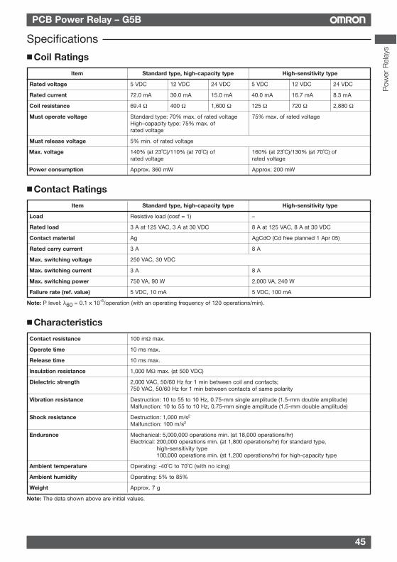
45
PCB Power Relay – G5B
Coil Ratings
Item Standard type, high-capacity type High-sensitivity type
Rated voltage 5 VDC 12 VDC 24 VDC 5 VDC 12 VDC 24 VDC
Rated current 72.0 mA 30.0 mA 15.0 mA 40.0 mA 16.7 mA 8.3 mA
Coil resistance 69.4 Ω 400 Ω 1,600 Ω 125 Ω 720 Ω 2,880 Ω
Must operate voltage Standard type: 70% max. of rated voltage 75% max. of rated voltageHigh–capacity type: 75% max. ofrated voltage
Must release voltage 5% min. of rated voltage
Max. voltage 140% (at 23˚C)/110% (at 70˚C) of 160% (at 23˚C)/130% (at 70˚C) of rated voltage rated voltage
Power consumption Approx. 360 mW Approx. 200 mW
Contact Ratings
Item Standard type, high-capacity type High-sensitivity type
Load Resistive load (cosf = 1) –
Rated load 3 A at 125 VAC, 3 A at 30 VDC 8 A at 125 VAC, 8 A at 30 VDC
Contact material Ag AgCdO (Cd free planned 1 Apr 05)
Rated carry current 3 A 8 A
Max. switching voltage 250 VAC, 30 VDC
Max. switching current 3 A 8 A
Max. switching power 750 VA, 90 W 2,000 VA, 240 W
Failure rate (ref. value) 5 VDC, 10 mA 5 VDC, 100 mA
Note: P level: λ60 = 0.1 x 10⁻⁶/operation (with an operating frequency of 120 operations/min).
Characteristics
Contact resistance 100 mΩ max.
Operate time 10 ms max.
Release time 10 ms max.
Insulation resistance 1,000 MΩ max. (at 500 VDC)
Dielectric strength 2,000 VAC, 50/60 Hz for 1 min between coil and contacts;750 VAC, 50/60 Hz for 1 min between contacts of same polarity
Vibration resistance Destruction: 10 to 55 to 10 Hz, 0.75-mm single amplitude (1.5-mm double amplitude)Malfunction: 10 to 55 to 10 Hz, 0.75-mm single amplitude (1.5-mm double amplitude)
Shock resistance Destruction: 1,000 m/s2
Malfunction: 100 m/s2
Endurance Mechanical: 5,000,000 operations min. (at 18,000 operations/hr)Electrical: 200,000 operations min. (at 1,800 operations/hr) for standard type,
high-sensitivity type100,000 operations min. (at 1,200 operations/hr) for high-capacity type
Ambient temperature Operating: -40˚C to 70˚C (with no icing)
Ambient humidity Operating: 5% to 85%
Weight Approx. 7 g
Note: The data shown above are initial values.
Specifications
Pow
er R
elay
s
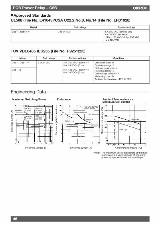
46
PCB Power Relay – G5B
Approved StandardsUL508 (File No. E41643)/CSA C22.2 No.0, No.14 (File No. LR31928)
Model Coil ratings Contact ratings
G5B-1, G5B-1-H 3 to 24 VDC 3 A, 250 VAC (general use)3 A, 30 VDC (resistive)1/8 hp, 125 VAC/1/8 hp, 250 VACTV-2 125 VAC
Engineering Data
Maximum Switching Power Endurance Ambient Temperature vs. Maximum Coil Voltage
Sw
itchi
ng c
urre
nt (
A)
Max
imum
coi
l vol
tage
(%
)
Switching voltage (V) Switching current (A) Ambient temperature (°C)
End
uran
ce (
x10
ope
ratio
ns)
3
G5B-1-E DC resistive
G5B-1(-H)DC resistive
G5B-1-EAC resistive load
G5B-1(-H)AC resistive load
G5B-1 (-H)G5B-1-E
125-VAC,30-VDC resistive load
G5B-1-H
G5B-1 (-E)
Note: The maximum coil voltage refers to the maxi-mum value in a varying range of operating power voltage, not a continuous voltage.
TÜV VDE0435 IEC255 (File No. R9251225)
Model Coil ratings Contact ratings Condition
G5B-1, G5B-1-H 3 to 24 VDC 3 A, 250 VAC~ (cosø = 1)3 A, 30 VDC= (0 ms)
G5B-1-E 8 A, 125 VAC~ (cosø = 1)8 A, 30 VDC= (0 ms)
Duty level: class IIIOperative range: 2Pick–up class: class aPollution degree: 2Overvoltage category: IIMaterial group: IIIaAmbient temperature: -40˚C to 70˚C
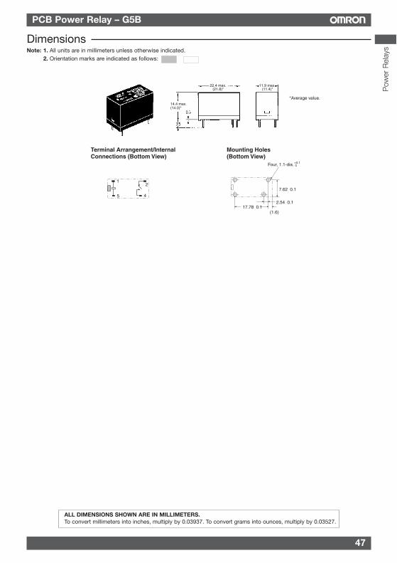
47
PCB Power Relay – G5B
DimensionsNote: 1. All units are in millimeters unless otherwise indicated.
2. Orientation marks are indicated as follows:
Terminal Arrangement/Internal Connections (Bottom View)
Mounting Holes(Bottom View)
(1.6)
+0.1 0Four, 1.1-dia.
7.62±0.1
2.54±0.117.78±0.1
1
5 4
2
14.4 max.(14.0)*
22.4 max.(21.8)*
11.9 max.(11.4)*
*Average value.
ALL DIMENSIONS SHOWN ARE IN MILLIMETERS.To convert millimeters into inches, multiply by 0.03937. To convert grams into ounces, multiply by 0.03527.
Pow
er R
elay
s
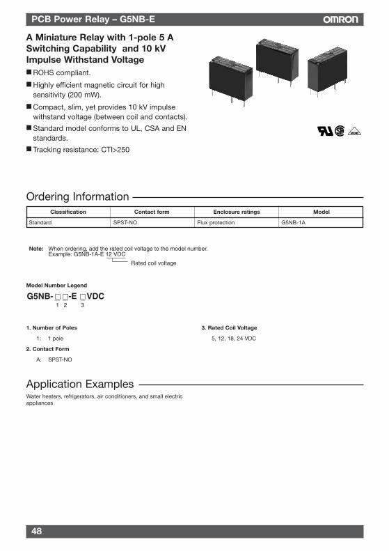
48
PCB Power Relay – G5NB-E
Ordering Information
A Miniature Relay with 1-pole 5 ASwitching Capability and 10 kVImpulse Withstand Voltage ROHS compliant.
Highly efficient magnetic circuit for highsensitivity (200 mW).
Compact, slim, yet provides 10 kV impulsewithstand voltage (between coil and contacts).
Standard model conforms to UL, CSA and ENstandards.
Tracking resistance: CTI>250
RC
Classification Contact form Enclosure ratings Model
Standard SPST-NO Flux protection G5NB-1A
Rated coil voltage
Note: When ordering, add the rated coil voltage to the model number.Example: G5NB-1A-E 12 VDC
Model Number Legend
1. Number of Poles 3. Rated Coil Voltage
1: 1 pole 5, 12, 18, 24 VDC
2. Contact Form
A: SPST-NO
1 2 3-E
Water heaters, refrigerators, air conditioners, and small electricappliances
Application Examples
49
PCB Power Relay – G5NB-E
Rated voltage 5 VDC 12 VDC 18 VDC 24 VDC
Rated current 40.0 mA 16.7 mA 11.1 mA 8.3 mA
Coil resistance 125 Ω 720 Ω 1,620 Ω 2,880 Ω
Must operate voltage 75% max. of rated voltage
Must release voltage 10% min. of rated voltage
Max. voltage 170% of rated voltage (at 23°C)
Power consumption Approx. 200 mW
Note: The rated current and coil resistance are measured at a coil temperature of 23°C with a tolerance of ±10%.The operating characteristics are measured at a coil temperature of 23°C.The “Max. voltage” is the maximum voltage that can be applied to the relay coil.
Specifications Coil Ratings
Contact Ratings
Load Resistive load (cosφ = 1)
Rated load 5 A at 250 VAC, 3 A at 30 VDC
Max. switching voltage 250 VAC, 30 VDC
Max. switching current 5 A
Max. switching power 1250 VA, 90 W
Failure rate (reference value) 10 mA at 5 VDC
Note: P level: λ60 = 0.1 x 10⁻⁶/operation (with an operating frequency of 120 operations/min)
Characteristics
Contact resistance (See note 2.) 100 mΩ max.
Operate time 10 ms max.
Release time 10 ms max.
Insulation resistance (See note 3.) 1,000 MΩ min. (at 500 VDC)
Dielectric strength 4,000 VAC, 50/60 Hz for 1 min between coil and contacts750 VAC, 50/60 Hz for 1 min between contacts of same polarity
Impulse withstand voltage 10,000 V (1.2 x 50 ms) between coil and contacts
Vibration resistance Destruction: 10 to 55 to 10 Hz, 0.75-mm single amplitude (1.5-mm double amplitude)Malfunction: 10 to 55 to 10 Hz, 0.75-mm single amplitude (1.5-mm double amplitude)
Shock resistance Destruction: 1,000 m/s2
Malfunction: 100 m/s2
Endurance Mechanical: 5,000,000 operations min.Electrical: 100,000 operations min (5 A at 250 VAC), 200,000 operations min. (3 A at 30 VDC)
Failure rate P level (reference value) 5 VDC, 10 mA(See note 4.)
Ambient temperature Operating: -40˚C to 85˚C (with no icing or condensation)
Ambient humidity Operating: 5% to 85%
Weight Approx. 4 g
Note: 1. The data shown above are initial value.2. Measurement conditions: 5 VDC, 1 A, voltage drop method.3. Measurement conditions: Measured at the same points as the dielectric strength using a 500-VDC ohmmeter.4. This value is for a switching frequency of 120 operations/minute.
Pow
er R
elay
s
50
PCB Power Relay – G5NB-E
Approved StandardsUL508 (File No. 41515)
Coil ratings Contact ratings
5 to 24 VDC 5 A, 30 VDC (resistive)5 A, 125 VAC (resistive)5 A, 250 VAC (general use)
CSA C22.2 (No. 0, No. 1, No. 14) (File No. LR31928)
Actual Load Life (Reference Values)
Coil ratings Contact ratings
5 to 24 VDC 5 A, 30 VDC (resistive)5 A, 125 VAC (resistive)5 A, 250 VAC (general use)
EN 61810-1 (VDE Reg No 137575)
Coil ratings Contact ratings
5 to 24VDC 5 A, 30 VDC (resistive)5 A, 250 VAC (general use)
1. 120-VAC motor and lamp load (2.5-A surge and 0.5-A normal): 250,000 operations min.(at 23°C) 2. 160-VDC valve load (with varistor) (0.24-A): 250,000 operations min.(at 23°C)
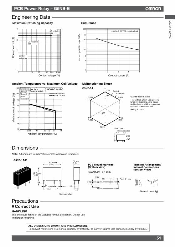
51
PCB Power Relay – G5NB-E
ALL DIMENSIONS SHOWN ARE IN MILLIMETERS.To convert millimeters into inches, multiply by 0.03937. To convert grams into ounces, multiply by 0.03527.
Correct Use
Contact voltage (V)
10
1 10 30 100 250 1,000
DC resistiveload
AC resistiveload
Contactresistance
Maximum Switching Capacity
Contact current (A)
100
50
30
10
5
3
10 1 2 3 4
250 VAC, 30 VDC resistive load
Endurance
Con
tact
cur
rent
(A
)
No.
of o
pera
tions
(x
104 )
5
3
1
0.1
Precautions
HANDLINGThe enclosure rating of the G5NB is for flux protection. Do not useimmersion-cleaning.
DimensionsNote: All units are in millimeters unless otherwise indicated.
PCB Mounting Holes (Bottom View)
Tolerance: ±0.1 mm
Terminal Arrangement/Internal Connections(Bottom View)
7.2 max.(7.0)*
Four, 1.1 dia.
(No coil polarity)*Average value
15. 3 max.(15.0)*
3.4
0.4
11.5 7
0.27 0.33
20.5 max.(20.4)*
G5NB-1A-E
Engineering Data
Pow
er R
elay
s
Ambient Temperature vs. Maximum Coil Voltage
Max
imum
coi
l vol
tage
(%
)
Ambient temperature (°C)
Test item: G5NB-1A-E, 24 VDCQuantity tested: 5
No current3-A current
Z
Z
Z’
Z’
Shock directionUnit: m/s2
Y
Y
Y’
Y’
X
X
X’
X’
1,000
1,000
1,000 1,000
1,000 1,000
ExcitedNot excited
700
125
Malfunctioning Shock
G5NB-1A
Quantity Tested: 5 units
Test Method: Shock was applied 3 times in 6 directions along 3 axes and the level at which shock caused malfunction was measured.
Rating: 100 m/s2
Uncon-firmed area
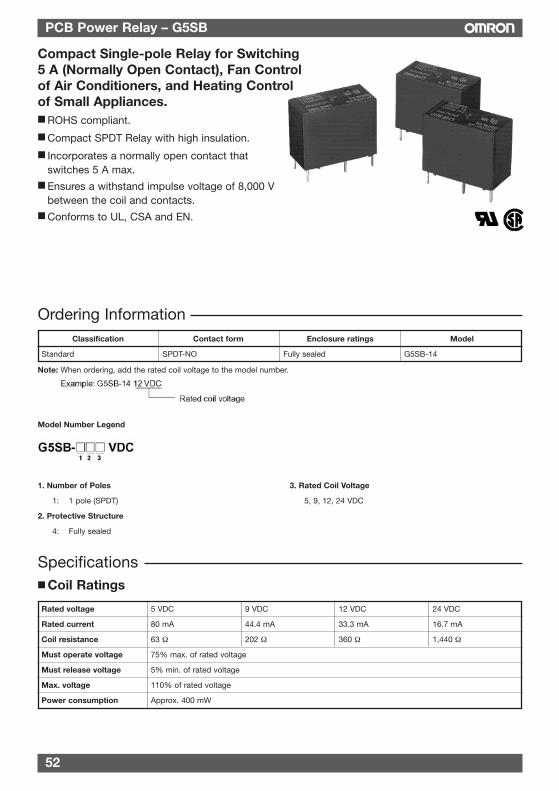
52
PCB Power Relay – G5SB
Note: When ordering, add the rated coil voltage to the model number.
Model Number Legend
1. Number of Poles 3. Rated Coil Voltage
1: 1 pole (SPDT) 5, 9, 12, 24 VDC
2. Protective Structure
4: Fully sealed
Ordering Information
Compact Single-pole Relay for Switching5 A (Normally Open Contact), Fan Controlof Air Conditioners, and Heating Controlof Small Appliances. ROHS compliant.
Compact SPDT Relay with high insulation.
Incorporates a normally open contact thatswitches 5 A max.
Ensures a withstand impulse voltage of 8,000 Vbetween the coil and contacts.
Conforms to UL, CSA and EN.
Classification Contact form Enclosure ratings Model
Standard SPDT-NO Fully sealed G5SB-14
Rated voltage 5 VDC 9 VDC 12 VDC 24 VDC
Rated current 80 mA 44.4 mA 33.3 mA 16.7 mA
Coil resistance 63 Ω 202 Ω 360 Ω 1,440 Ω
Must operate voltage 75% max. of rated voltage
Must release voltage 5% min. of rated voltage
Max. voltage 110% of rated voltage
Power consumption Approx. 400 mW
Specifications Coil Ratings
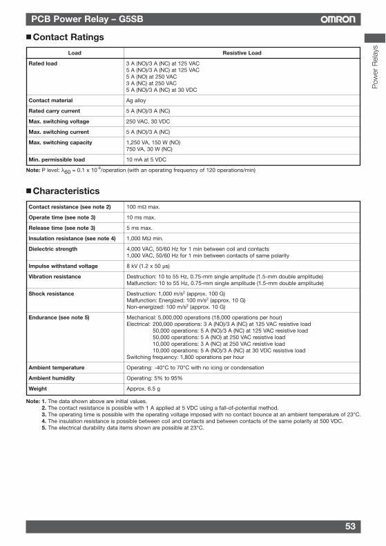
53
PCB Power Relay – G5SB
Contact Ratings
Load Resistive Load
Rated load 3 A (NO)/3 A (NC) at 125 VAC5 A (NO)/3 A (NC) at 125 VAC5 A (NO) at 250 VAC3 A (NC) at 250 VAC5 A (NO)/3 A (NC) at 30 VDC
Contact material Ag alloy
Rated carry current 5 A (NO)/3 A (NC)
Max. switching voltage 250 VAC, 30 VDC
Max. switching current 5 A (NO)/3 A (NC)
Max. switching capacity 1,250 VA, 150 W (NO)750 VA, 30 W (NC)
Min. permissible load 10 mA at 5 VDC
Note: P level: λ60 = 0.1 x 10⁻⁶/operation (with an operating frequency of 120 operations/min)
Characteristics
Contact resistance (see note 2) 100 mΩ max.
Operate time (see note 3) 10 ms max.
Release time (see note 3) 5 ms max.
Insulation resistance (see note 4) 1,000 MΩ min.
Dielectric strength 4,000 VAC, 50/60 Hz for 1 min between coil and contacts1,000 VAC, 50/60 Hz for 1 min between contacts of same polarity
Impulse withstand voltage 8 kV (1.2 x 50 µs)
Vibration resistance Destruction: 10 to 55 Hz, 0.75-mm single amplitude (1.5-mm double amplitude)Malfunction: 10 to 55 Hz, 0.75-mm single amplitude (1.5-mm double amplitude)
Shock resistance Destruction: 1,000 m/s2 (approx. 100 G)Malfunction: Energized: 100 m/s2 (approx. 10 G)Non-energized: 100 m/s2 (approx. 10 G)
Endurance (see note 5) Mechanical: 5,000,000 operations (18,000 operations per hour)Electrical: 200,000 operations: 3 A (NO)/3 A (NC) at 125 VAC resistive load
50,000 operations: 5 A (NO)/3 A (NC) at 125 VAC resistive load50,000 operations: 5 A (NO) at 250 VAC resistive load10,000 operations: 3 A (NC) at 250 VAC resistive load10,000 operations: 5 A (NO)/3 A (NC) at 30 VDC resistive load
Switching frequency: 1,800 operations per hour
Ambient temperature Operating: -40°C to 70°C with no icing or condensation
Ambient humidity Operating: 5% to 95%
Weight Approx. 6.5 g
Note: 1. The data shown above are initial values.2. The contact resistance is possible with 1 A applied at 5 VDC using a fall-of-potential method.3. The operating time is possible with the operating voltage imposed with no contact bounce at an ambient temperature of 23°C.4. The insulation resistance is possible between coil and contacts and between contacts of the same polarity at 500 VDC.5. The electrical durability data items shown are possible at 23°C.
Pow
er R
elay
s
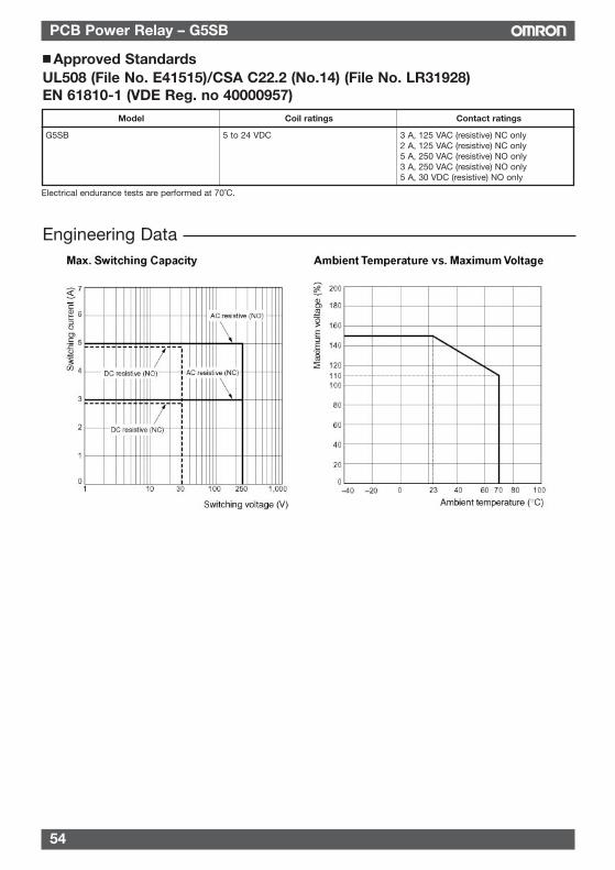
54
PCB Power Relay – G5SB
Engineering Data
Approved StandardsUL508 (File No. E41515)/CSA C22.2 (No.14) (File No. LR31928)EN 61810-1 (VDE Reg. no 40000957)
Model Coil ratings Contact ratings
G5SB 5 to 24 VDC 3 A, 125 VAC (resistive) NC only2 A, 125 VAC (resistive) NC only5 A, 250 VAC (resistive) NO only3 A, 250 VAC (resistive) NO only5 A, 30 VDC (resistive) NO only
Electrical endurance tests are performed at 70˚C.
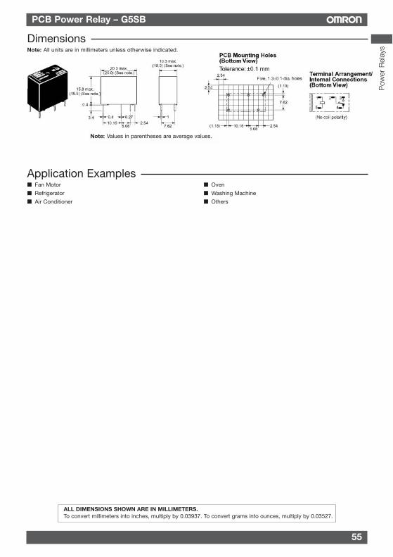
55
PCB Power Relay – G5SB
Terminals separated from PCB
DimensionsNote: All units are in millimeters unless otherwise indicated.
Application Examples Fan Motor Oven
Refrigerator Washing Machine
Air Conditioner Others
Note: Values in parentheses are average values.
ALL DIMENSIONS SHOWN ARE IN MILLIMETERS.To convert millimeters into inches, multiply by 0.03937. To convert grams into ounces, multiply by 0.03527.
Pow
er R
elay
s
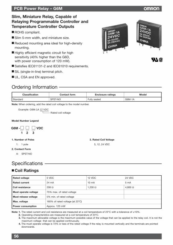
56
PCB Power Relay – G6M
Note: When ordering, add the rated coil voltage to the model number.
Model Number Legend
1. Number of Poles 3. Rated Coil Voltage
1: 1 pole 5, 12, 24 VDC
2. Contact Form
A: SPST-NO
Ordering Information
Slim, Miniature Relay, Capable ofRelaying Programmable Controller andTemperature Controller Outputs ROHS compliant.
Slim 5-mm width, and miniature size.
Reduced mounting area ideal for high-densitymounting.
Highly efficient magnetic circuit for highsensitivity (40% higher than the G6D,with power consumption of 120 mW).
Satisfies IEC61131-2 and IEC61010 requirements.
SIL (single-in-line) terminal pitch.
UL, CSA and EN approved.
Classification Contact form Enclosure ratings Model
Standard SPST-NO Fully sealed G6M-1A
Rated voltage 5 VDC 12 VDC 24 VDC
Rated current 24 mA 10 mA 5 mA
Coil resistance 208 Ω 1,200 Ω 4,800 Ω
Must operate voltage 75% max. of rated voltage
Must release voltage 5% min. of rated voltage
Max. voltage 160% of rated voltage (at 23°C)
Power consumption Approx. 120 mW
Specifications Coil Ratings
Rated coil voltageExample: G6M-1A 12 VDC
G6M - VDC1 2 3
Note: 1. The rated current and coil resistance are measured at a coil temperature of 23°C with a tolerance of ±10%.2. Operating characteristics are measured at a coil temperature of 23°C.3. The maximum allowable voltage is the maximum possible value of the voltage that can be applied to the relay coil. It is not the
maximum voltage that can be applied continuously.4. The must operate voltage is 72% or less of the rated voltage if the relay is mounted vertically and the terminals are pointed
downwards.
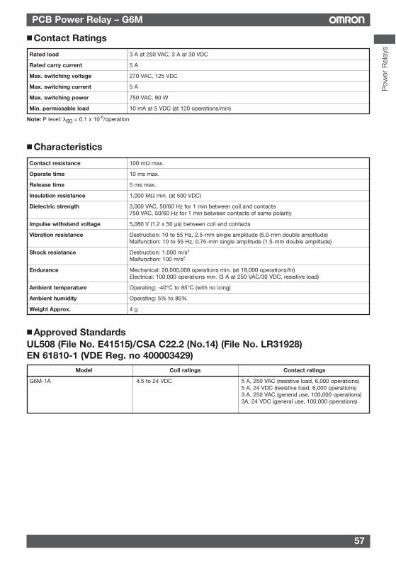
57
PCB Power Relay – G6M
Contact Ratings
Rated load 3 A at 250 VAC, 3 A at 30 VDC
Rated carry current 5 A
Max. switching voltage 270 VAC, 125 VDC
Max. switching current 5 A
Max. switching power 750 VAC, 90 W
Min. permissable load 10 mA at 5 VDC (at 120 operations/min)
Note: P level: λ60 = 0.1 x 10⁻⁶/operation
Characteristics
Contact resistance 100 mΩ max.
Operate time 10 ms max.
Release time 5 ms max.
Insulation resistance 1,000 MΩ min. (at 500 VDC)
Dielectric strength 3,000 VAC, 50/60 Hz for 1 min between coil and contacts750 VAC, 50/60 Hz for 1 min between contacts of same polarity
Impulse withstand voltage 5,080 V (1.2 x 50 µs) between coil and contacts
Vibration resistance Destruction: 10 to 55 Hz, 2.5-mm single amplitude (5.0-mm double amplitude)Malfunction: 10 to 55 Hz, 0.75-mm single amplitude (1.5-mm double amplitude)
Shock resistance Destruction: 1,000 m/s2
Malfunction: 100 m/s2
Endurance Mechanical: 20,000,000 operations min. (at 18,000 operations/hr)Electrical: 100,000 operations min. (3 A at 250 VAC/30 VDC, resistive load)
Ambient temperature Operating: -40°C to 85°C (with no icing)
Ambient humidity Operating: 5% to 85%
Weight Approx. 4 g
Approved StandardsUL508 (File No. E41515)/CSA C22.2 (No.14) (File No. LR31928)EN 61810-1 (VDE Reg. no 400003429)
Model Coil ratings Contact ratings
G6M-1A 4.5 to 24 VDC 5 A, 250 VAC (resistive load, 6,000 operations)5 A, 24 VDC (resistive load, 6,000 operations)3 A, 250 VAC (general use, 100,000 operations)3A, 24 VDC (general use, 100,000 operations)
Pow
er R
elay
s
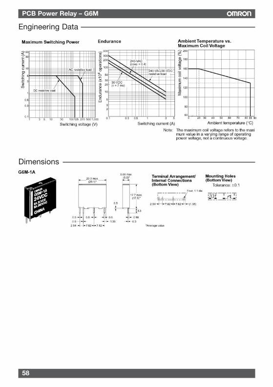
58
PCB Power Relay – G6M
Engineering Data
Dimensions
59
PCB Power Relay – G6M
PrecautionsBASIC INFORMATIONBefore actually committing any component to a mass-productionsituation, OMRON strongly recommends situationaltesting, in as close to actual production situations as possible.One reason is to confirm that the product will still perform asexpected after surviving the many handling and mountingprocesses involved in mass production. Also, even thoughOMRON relays are individually tested a number of times, andeach meets strict requirements, a certain testing tolerance ispermissible. When a high-precision product uses manycomponents, each depends upon the rated performancethresholds of the other components. Thus, the overallperformance tolerance may accumulate into undesirable levels.To avoid problems, always conduct tests under the actualapplication conditions.
GeneralTo maintain the initial characteristics of a relay, exercise carethat it is not dropped or mishandled. For the same reason, do notremove the case of the relay; otherwise, the characteristics maydegrade. Avoid using the relay in an atmosphere containingsulfuric acid (SO2), hydrogen sulfide (H2S), or other corrosivegases.Do not continuously apply a voltage higher than the ratedmaximum voltage to the relay. Never try to operate the relay at avoltage and a current other than those rated.Do not use the relay at temperatures higher than that specified inthe catalog or data sheet.
ALL DIMENSIONS SHOWN ARE IN MILLIMETERS.To convert millimeters into inches, multiply by 0.03937. To convert grams into ounces, multiply by 0.03527.
Pow
er R
elay
s
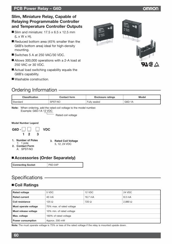
60
PCB Power Relay – G6D
Model Number Legend
Ordering Information
Slim, Miniature Relay, Capable ofRelaying Programmable Controllerand Temperature Controller Outputs Slim and miniature: 17.5 x 6.5 x 12.5 mm
(L x W x H). Reduced bottom area (45% smaller than the
G6B’s bottom area) ideal for high-densitymounting.
Switches 5 A at 250 VAC/30 VDC.
Allows 300,000 operations with a 2-A load at250 VAC or 30 VDC.
Actual load switching capability equals theG6B’s capability.
Washable construction.
Rated coil voltage
Note: When ordering, add the rated coil voltage to the model number.Example: G6D-1A 12 VDC
G6D - VDC1 2 3
1. Number of Poles 1: 1 pole
2. Contact Form A: SPST-NO
3. Rated Coil Voltage 5, 12, 24 VDC
Classification Contact form Enclosure ratings Model
Standard SPST-NO Fully sealed G6D-1A
Accessories (Order Separately)
Connecting Socket P6D-04P
Rated voltage 5 VDC 12 VDC 24 VDC
Rated current 40 mA 16.7 mA 8.3 mA
Coil resistance 125 Ω 720 Ω 2,880 Ω
Must operate voltage 70% max. of rated voltage
Must release voltage 10% min. of rated voltage
Max. voltage 160% of rated voltage
Power consumption Approx. 200 mW
Note: The must operate voltage is 75% or less of the rated voltage if the relay is mounted upside down.
Specifications Coil Ratings
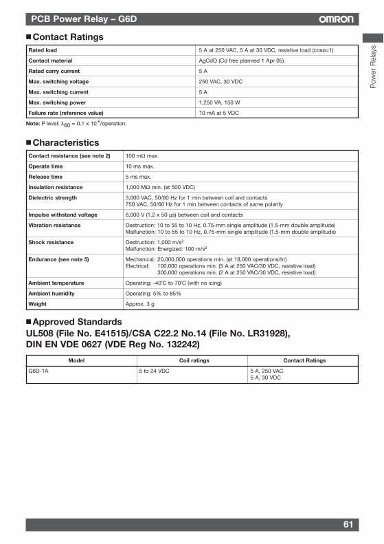
PCB Power Relay – G6D
CharacteristicsContact resistance (see note 2) 100 mΩ max.
Operate time 10 ms max.
Release time 5 ms max.
Insulation resistance 1,000 MΩ min. (at 500 VDC)
Dielectric strength 3,000 VAC, 50/60 Hz for 1 min between coil and contacts750 VAC, 50/60 Hz for 1 min between contacts of same polarity
Impulse withstand voltage 6,000 V (1.2 x 50 µs) between coil and contacts
Vibration resistance Destruction: 10 to 55 to 10 Hz, 0.75-mm single amplitude (1.5-mm double amplitude)Malfunction: 10 to 55 to 10 Hz, 0.75-mm single amplitude (1.5-mm double amplitude)
Shock resistance Destruction: 1,000 m/s2
Malfunction: Energized: 100 m/s2
Endurance (see note 5) Mechanical: 20,000,000 operations min. (at 18,000 operations/hr)Electrical: 100,000 operations min. (5 A at 250 VAC/30 VDC, resistive load)
300,000 operations min. (2 A at 250 VAC/30 VDC, resistive load)
Ambient temperature Operating: -40˚C to 70˚C (with no icing)
Ambient humidity Operating: 5% to 85%
Weight Approx. 3 g
Approved StandardsUL508 (File No. E41515)/CSA C22.2 No.14 (File No. LR31928),DIN EN VDE 0627 (VDE Reg No. 132242)
Model Coil ratings Contact Ratings
G6D-1A 5 to 24 VDC 5 A, 250 VAC5 A, 30 VDC
Pow
er R
elay
s
Contact RatingsRated load 5 A at 250 VAC, 5 A at 30 VDC, resistive load (cosø=1)
Contact material AgCdO (Cd free planned 1 Apr 05)
Rated carry current 5 A
Max. switching voltage 250 VAC, 30 VDC
Max. switching current 5 A
Max. switching power 1,250 VA, 150 W
Failure rate (reference value) 10 mA at 5 VDC
Note: P level: λ60 = 0.1 x 10⁻⁶/operation.
61
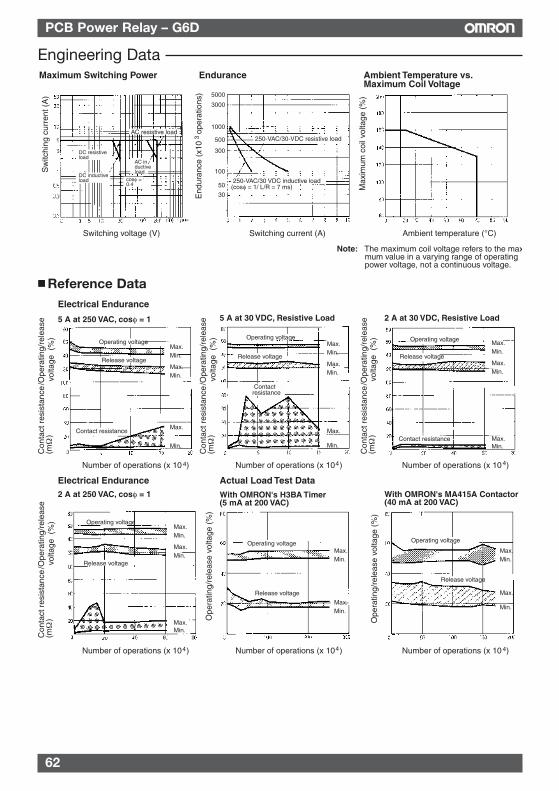
62
PCB Power Relay – G6D
Electrical Endurance
5 A at 250 VAC, cosφ = 1
Number of operations (x 10 )
5 A at 30 VDC, Resistive Load 2 A at 30 VDC, Resistive Load
Operating voltage
Release voltage
Contact resistance
Max.Min.
Max.Min.
Max.
Min.
Contact resistance
Operating voltage
Release voltage
Max.Min.
Max.Min.
Max.
Min.
Operating voltage
Release voltage
Contact resistance
Max.Min.
Max.Min.
Max.Min.
Number of operations (x 10 ) Number of operations (x 10 )
Contact resistance
Operating voltage
Release voltage
Max.Min.
Max.Min.
Max.Min.
Operating voltage
Release voltage
Max.Min.
Max.Min.
Operating voltage
Release voltage
Max.Min.
Max.
Min.
Electrical Endurance2 A at 250 VAC, cosφ = 1
Actual Load Test Data
With OMRON's H3BA Timer (5 mA at 200 VAC)
With OMRON's MA415A Contactor (40 mA at 200 VAC)
Number of operations (x 10 ) Number of operations (x 10 ) Number of operations (x 10 )
Ope
ratin
g/re
leas
e vo
ltage
(%
)
Ope
ratin
g/re
leas
e vo
ltage
(%
)
/Ope
ratin
g/re
leas
evo
ltage
(%
)C
onta
ct r
esis
tanc
e(m
)
Ω
/Ope
ratin
g/re
leas
evo
ltage
(%
)C
onta
ct r
esis
tanc
e(m
)
Ω
/Ope
ratin
g/re
leas
evo
ltage
(%
)C
onta
ct r
esis
tanc
e(m
)
Ω
/Ope
ratin
g/re
leas
evo
ltage
(%
)C
onta
ct r
esis
tanc
e(m
)
Ω
4 4 4
444
Reference Data
Engineering DataMaximum Switching Power Ambient Temperature vs.
Maximum Coil VoltageEndurance
Sw
itchi
ng c
urre
nt (
A)
Switching voltage (V) Switching current (A)
End
uran
ce (
x10
ope
ratio
ns)
3
Ambient temperature (°C)
Max
imum
coi
l vol
tage
(%
)
AC resistive load
AC inductive load
DC resistive load
DC inductive load cosφ =
0.4
5000
3000
1000
500
300
100
50
30
250-VAC/30-VDC resistive load
250-VAC/30 VDC inductive load(cosφ = 1/ L/R = 7 ms)
Note: The maximum coil voltage refers to the maxmum value in a varying range of operating power voltage, not a continuous voltage.
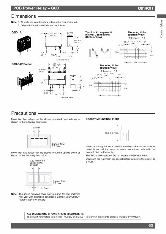
63
PCB Power Relay – G6D
More than two relays can be closely mounted right side up asshown in the following illustration.
More than two relays can be closely mounted upside down asshown in the following illustration.
Note: The space between each relay required for heat radiationmay vary with operating conditions. Contact your OMRONrepresentative for details
SOCKET MOUNTING HEIGHT
When mounting the relay, insert it into the socket as vertically aspossible so that the relay terminals contact securely with thecontact pins on the socket.The P6D is flux-resistive. Do not wash the P6D with water.Dismount the relay from the socket before soldering the socket toa PCB.
Current flow: 5 A max.
6.5 mm
7.62 mm in the upside-down direction
1.12 mm
Current flow: 2 A max.
18.5 mm max.
Precautions
G6D-1A Terminal Arrangement/Internal Connections (Bottom View)
Mounting Holes(Bottom View)Tolerance: ±0.1
P6D-04P Socket
0.5
12.5 max.
17.5 max.
2.540.3
3.5
5.087.62.
0.8
5.08
0.5
(17.3)*
(12.4)*
6.5 max.
(6.4)*
2.54
3.6
10.8
0.65 0.3
5.0876.2
19.7 max.
6.9 max.(6.7)*
6+0.1
(19.5)*
1
13
5 7
(1.13)
(0.71)
2.54
2.54
15.24
2.54
(2.18)
(0.86)
2.54
2.54
15.24
5.08
Mounting Holes(Bottom View)Tolerance: ±0.1
Four, 1.1-dia. holes
Four, 1.1-dia. holes
*Average value
*Average value
DimensionsNote: 1. All units are in millimeters unless otherwise indicated.
2. Orientation marks are indicated as follows:
ALL DIMENSIONS SHOWN ARE IN MILLIMETERS.To convert millimeters into inches, multiply by 0.03937. To convert grams into ounces, multiply by 0.03527.
Pow
er R
elay
s

64
PCB Power Relay – G6B
Model Number Legend
Ordering Information
Sub-miniature Relay that Switchesup to 5 A Sub-miniature: 20 x 10 x 10 mm (L x W x H).
Low power consumption: 200 mW.
Unique moving loop armature reduces relaysize, magnetic interference, and contactbounce time.
Single- and double-winding latching typesalso available.
Rated coil voltage
Note: When ordering, add the rated coil voltage to the model number.Example: G6B-1114P-US 12 VDC
1. Relay Function None: Single-side stable U: Single-winding latching K: Double-winding latching
2. Contact Form 21: SPST-NO + SPST-NC 22: DPST-NO 20: DPST-NC 11: SPST-NO
3. Contact Type 1: Standard 7: High-capacity
4. Enclosure Ratings 4: Fully sealed
5. Terminals P: Straight PCB C: Self-clinching PCB
6. Approved Standards US: UL/CSA certified
7. Rated Coil Voltage 5, 6, 12, 24 VDC
G6B - - VDC1 2 3 4 5 6 7
Classification Contact form Straight PCB Self-clinching PCB
Single-side stable SPST-NO G6B-1114P-US G6B-1114C-US
SPST-NO+SPST-NC G6B-2114P-US G6B-2114C-US
DPST-NO G6B-2214P-US G6B-2214C-US
DPST-NC G6B-2014P-US G6B-2014C-US
Single-winding latching SPST-NO G6BU-1114P-US G6BU-1114C-US
Double-winding latching SPST-NO G6BK-1114P-US G6BK-1114C-US
High-capacity single-side stable SPST-NO G6B-1174P-US G6B-1174C-US
Accessories (Order Separately)Back Connecting Sockets
Applicable relay Back connecting socket*
G6B(U)-1114P-US P6B-04P
G6BK-1114P-US P6B-06P
G6B-2114P-US P6B-26P
G6B-1174P-US P6B-04P
*Not applicable to the self-clinching type.
Removal Tool P6B-Y1
Hold-down Clips P6B-C2
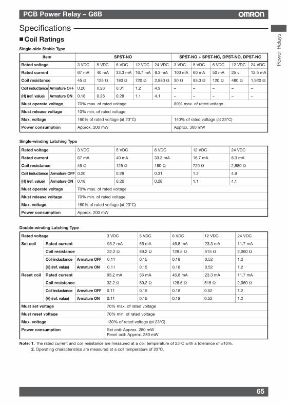
65
PCB Power Relay – G6B
Pow
er R
elay
s
Specifications Coil RatingsSingle-side Stable Type
Item SPST-NO SPST-NO + SPST-NC, DPST-NO, DPST-NC
Rated voltage 3 VDC 5 VDC 6 VDC 12 VDC 24 VDC 3 VDC 5 VDC 6 VDC 12 VDC 24 VDC
Rated current 67 mA 40 mA 33.3 mA 16.7 mA 8.3 mA 100 mA 60 mA 50 mA 25 v 12.5 mA
Coil resistance 45 Ω 125 Ω 180 Ω 720 Ω 2,880 Ω 30 Ω 83.3 Ω 120 Ω 480 Ω 1,920 Ω
0.20 0.28 0.31 1.2 4.9 – – – – –
0.18 0.26 0.28 1.1 4.1 – – – – –
Must operate voltage 70% max. of rated voltage 80% max. of rated voltage
Must release voltage 10% min. of rated voltage
Max. voltage 160% of rated voltage (at 23°C) 140% of rated voltage (at 23°C)
Power consumption Approx. 200 mW Approx. 300 mW
Coil inductance Armature OFF
(H) (ref. value) Armature ON
Rated voltage 3 VDC 5 VDC 6 VDC 12 VDC 24 VDC
Rated current 67 mA 40 mA 33.3 mA 16.7 mA 8.3 mA
Coil resistance 45 Ω 125 Ω 180 Ω 720 Ω 2,880 Ω
Coil inductance Armature OFF 0.20 0.28 0.31 1.2 4.9
(H) (ref. value) Armature ON 0.18 0.26 0.28 1.1 4.1
Must operate voltage 70% max. of rated voltage
Must release voltage 70% min. of rated voltage
Max. voltage 160% of rated voltage (at 23°C)
Power consumption Approx. 200 mW
Single-winding Latching Type
Double-winding Latching Type
Rated voltage 3 VDC 5 VDC 6 VDC 12 VDC 24 VDC
Set coil Rated current 93.2 mA 56 mA 46.8 mA 23.3 mA 11.7 mA
Coil resistance 32.2 Ω 89.2 Ω 128.5 Ω 515 Ω 2,060 Ω
Coil inductance Armature OFF 0.11 0.15 0.18 0.52 1.2
(H) (ref. value) Armature ON 0.11 0.15 0.18 0.52 1.2
Reset coil Rated current 93.2 mA 56 mA 46.8 mA 23.3 mA 11.7 mA
Coil resistance 32.2 Ω 89.2 Ω 128.5 Ω 515 Ω 2,060 Ω
Coil inductance Armature OFF 0.11 0.15 0.18 0.52 1.2
(H) (ref. value) Armature ON 0.11 0.15 0.18 0.52 1.2
Must set voltage 70% max. of rated voltage
Must reset voltage 70% min. of rated voltage
Max. voltage 130% of rated voltage (at 23°C)
Power consumption Set coil: Approx. 280 mWReset coil: Approx. 280 mW
Note: 1. The rated current and coil resistance are measured at a coil temperature of 23°C with a tolerance of ±10%.2. Operating characteristics are measured at a coil temperature of 23°C.
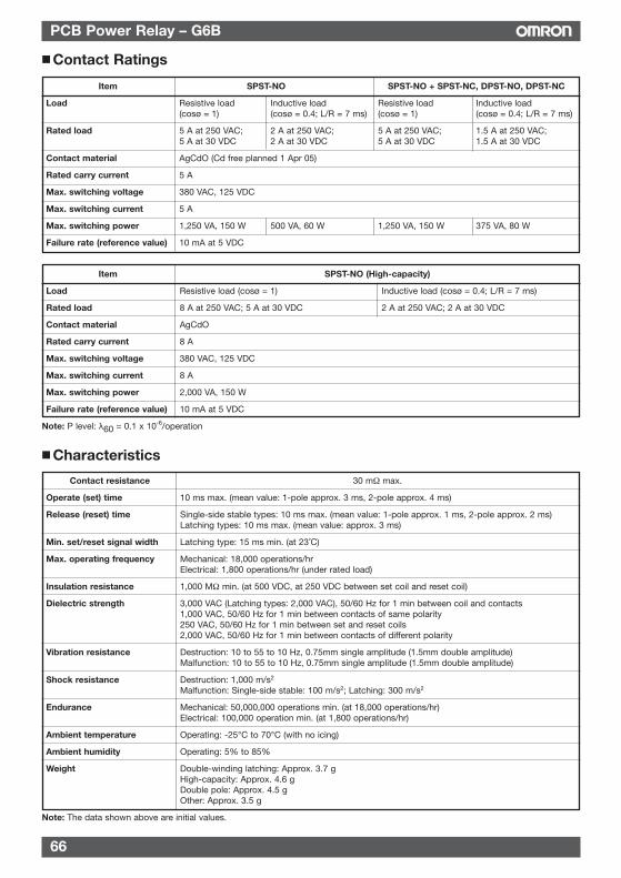
66
PCB Power Relay – G6B
Characteristics
Contact resistance 30 mΩ max.
Operate (set) time 10 ms max. (mean value: 1-pole approx. 3 ms, 2-pole approx. 4 ms)
Release (reset) time Single-side stable types: 10 ms max. (mean value: 1-pole approx. 1 ms, 2-pole approx. 2 ms)Latching types: 10 ms max. (mean value: approx. 3 ms)
Min. set/reset signal width Latching type: 15 ms min. (at 23˚C)
Max. operating frequency Mechanical: 18,000 operations/hrElectrical: 1,800 operations/hr (under rated load)
Insulation resistance 1,000 MΩ min. (at 500 VDC, at 250 VDC between set coil and reset coil)
Dielectric strength 3,000 VAC (Latching types: 2,000 VAC), 50/60 Hz for 1 min between coil and contacts1,000 VAC, 50/60 Hz for 1 min between contacts of same polarity250 VAC, 50/60 Hz for 1 min between set and reset coils2,000 VAC, 50/60 Hz for 1 min between contacts of different polarity
Vibration resistance Destruction: 10 to 55 to 10 Hz, 0.75mm single amplitude (1.5mm double amplitude)Malfunction: 10 to 55 to 10 Hz, 0.75mm single amplitude (1.5mm double amplitude)
Shock resistance Destruction: 1,000 m/s2
Malfunction: Single-side stable: 100 m/s2; Latching: 300 m/s2
Endurance Mechanical: 50,000,000 operations min. (at 18,000 operations/hr)Electrical: 100,000 operation min. (at 1,800 operations/hr)
Ambient temperature Operating: -25°C to 70°C (with no icing)
Ambient humidity Operating: 5% to 85%
Weight Double-winding latching: Approx. 3.7 gHigh-capacity: Approx. 4.6 gDouble pole: Approx. 4.5 gOther: Approx. 3.5 g
Note: The data shown above are initial values.
Item SPST-NO SPST-NO + SPST-NC, DPST-NO, DPST-NC
Load Resistive load Inductive load Resistive load Inductive load(cosø = 1) (cosø = 0.4; L/R = 7 ms) (cosø = 1) (cosø = 0.4; L/R = 7 ms)
Rated load 5 A at 250 VAC; 2 A at 250 VAC; 5 A at 250 VAC; 1.5 A at 250 VAC;5 A at 30 VDC 2 A at 30 VDC 5 A at 30 VDC 1.5 A at 30 VDC
Contact material AgCdO (Cd free planned 1 Apr 05)
Rated carry current 5 A
Max. switching voltage 380 VAC, 125 VDC
Max. switching current 5 A
Max. switching power 1,250 VA, 150 W 500 VA, 60 W 1,250 VA, 150 W 375 VA, 80 W
Failure rate (reference value) 10 mA at 5 VDC
Contact Ratings
Item SPST-NO (High-capacity)
Load Resistive load (cosø = 1) Inductive load (cosø = 0.4; L/R = 7 ms)
Rated load 8 A at 250 VAC; 5 A at 30 VDC 2 A at 250 VAC; 2 A at 30 VDC
Contact material AgCdO
Rated carry current 8 A
Max. switching voltage 380 VAC, 125 VDC
Max. switching current 8 A
Max. switching power 2,000 VA, 150 W
Failure rate (reference value) 10 mA at 5 VDC
Note: P level: λ60 = 0.1 x 10⁻⁶/operation
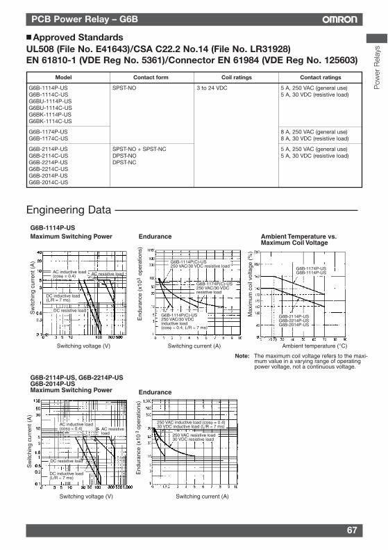
67
PCB Power Relay – G6B
Pow
er R
elay
s
Approved StandardsUL508 (File No. E41643)/CSA C22.2 No.14 (File No. LR31928)EN 61810-1 (VDE Reg No. 5361)/Connector EN 61984 (VDE Reg No. 125603)
Model Contact form Coil ratings Contact ratings
G6B-1114P-US SPST-NO 3 to 24 VDC 5 A, 250 VAC (general use)G6B-1114C-US 5 A, 30 VDC (resistive load)G6BU-1114P-USG6BU-1114C-USG6BK-1114P-USG6BK-1114C-US
G6B-1174P-US 8 A, 250 VAC (general use)G6B-1174C-US 8 A, 30 VDC (resistive load)
G6B-2114P-US SPST-NO + SPST-NC 5 A, 250 VAC (general use)G6B-2114C-US DPST-NO 5 A, 30 VDC (resistive load)G6B-2214P-US DPST-NCG6B-2214C-USG6B-2014P-USG6B-2014C-US
Engineering Data
G6B-1114P(C)-US250 VAC/30 VDC inductive load(cosφ = 0.4, L/R = 7 ms)
G6B-1174P(C)-US250 VAC/30 VDC resistive load
G6B-1114P(C)-US250 VAC/30 VDC resistive load
G6B-1114P-USMaximum Switching Power
Switching voltage (V)
Endurance Ambient Temperature vs. Maximum Coil Voltage
G6B-2114P-US, G6B-2214P-US G6B-2014P-USMaximum Switching Power Endurance
End
uran
ce (
x10
ope
ratio
ns)
3
Sw
itchi
ng c
urre
nt (
A)
Max
imum
coi
l vol
tage
(%
)
End
uran
ce (
x10
ope
ratio
ns)
3
Switching current (A) Ambient temperature (°C)
Switching voltage (V) Switching current (A)
Sw
itchi
ng c
urre
nt (
A)
AC resistive loadAC inductive load (cosφ = 0.4)
DC inductive load (L/R = 7 ms)
DC resistive load
AC inductive load (cosφ = 0.4) AC resistive
load
DC resistive load
DC inductive load (L/R = 7 ms)
G6B-2114P-USG6B-2214P-USG6B-2014P-US
G6B-1174P-USG6B-1114P-US
250 VAC inductive load (cosφ = 0.4)30 VDC inductive load (L/R = 7 ms)
250 VAC resistive load30 VDC resistive load
Note: The maximum coil voltage refers to the maxi-mum value in a varying range of operating power voltage, not a continuous voltage.
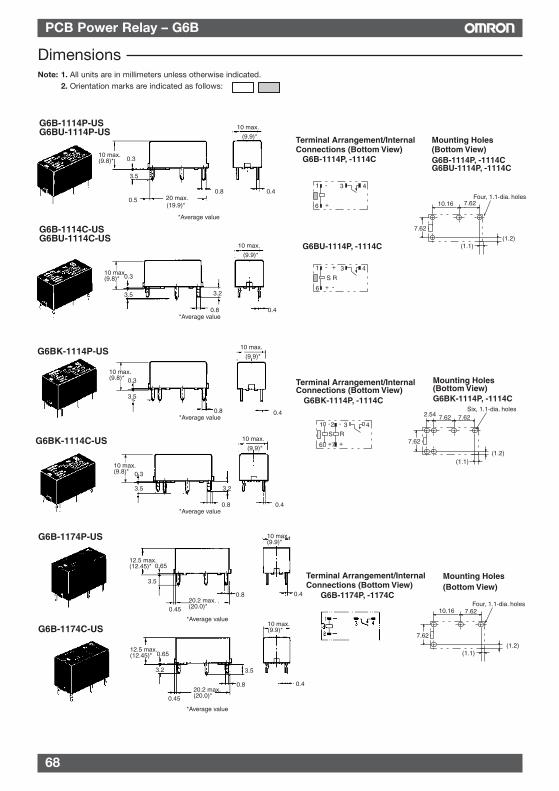
68
PCB Power Relay – G6B
DimensionsNote: 1. All units are in millimeters unless otherwise indicated.
2. Orientation marks are indicated as follows:
Terminal Arrangement/Internal Connections (Bottom View)
Mounting Holes (Bottom View)
G6B-1114P-USG6BU-1114P-US
G6BU-1114P, -1114C
G6B-1114P, -1114CG6BU-1114P, -1114C
G6B-1114C-USG6BU-1114C-US
10 max.(9.8)* 0.3
3.5
0.5 20 max.0.8 0.4
10 max.
G6B-1114P, -1114C
0.3
3.5
0.8 0.4
3.2
7.62
10.16 7.62
(1.1)(1.2)
Four, 1.1-dia. holes
6
1 3 4-
+
6
1 3 4-
+
S R
+
-
(19.9)*
*Average value
(9.9)*
10 max.
(9.9)*
10 max.(9.8)*
*Average value
G6BK-1114P-US
G6BK-1114P, -1114C G6BK-1114P, -1114C
G6BK-1114C-US
0.3
3.5
0.8 0.4
0.3
3.5
0.8 0.4
3.2
Terminal Arrangement/Internal Connections (Bottom View)
Mounting Holes (Bottom View)
7.62
7.62
2.54 7.62
(1.1)(1.2)
Six, 1.1-dia. holes
6
1 3 4-
+
S
7
2 -
+
R
10 max.(9.8)*
10 max.(9.8)*
10 max.
(9.9)*
10 max.
(9.9)*
*Average value
*Average value
Terminal Arrangement/Internal Connections (Bottom View)
G6B-1174P-US
G6B-1174C-US*Average value
*Average value
Mounting Holes (Bottom View)
G6B-1174P, -1174C
7.62
10.16 7.62
(1.1)(1.2)
Four, 1.1-dia. holes
12.5 max.(12.45)*
12.5 max.(12.45)*
0.65
0.65
3.5
3.2
0.45
0.4520.2 max.(20.0)*
20.2 max.(20.0)*
10 max.(9.9)*
10 max.(9.9)*
0.4
0.4
0.8
0.8
3.5
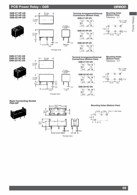
69
PCB Power Relay – G6B
Pow
er R
elay
s
G6B-2114P-USG6B-2214P-USG6B-2014P-US G6B-2114P-US
G6B-2214P-US
*Average value
20 max.(19.9)*
11 max.(10.9)*
11 max.(10.9)*
3.5
10.167.62
0.8
7.62
0.3
Tolerance: ±0.1
Terminal Arrangement/Internal Connections (Bottom View)
Mounting Holes (Bottom View)
8
1 3 4-
+6 5
8
1 3 4-
+6 5
G6B-2014P-US
8
1 3 4-
+6 5
(1.1)
(1.2)
10.16 7.62
Six, 1.1-dia. ±0.1 holes
7.62
G6B-2114C-USG6B-2214C-USG6B-2014C-US
*Average value
20 max.(19.9)*
11 max.(10.9)*
11 max.(10.9)*
3.5
10.16
3.2
7.62 7.62
0.8 0.3
G6B-2114C-US
G6B-2214C-US
Tolerance: ±0.1
Terminal Arrangement/Internal Connections (Bottom View)
Mounting Holes (Bottom View)
(1.1)
(1.2)
10.16 7.62
Six, 1.1-dia. ±0.1 holes
7.62
8
1 3 4-
+6 5
8
1 3 4-
+6 5
G6B-2014C-US
8
1 3 4-
+6 5
11 max.
(10.9)*
11 max.
(10.9)*
Back Connecting SocketP6B-04P
Mounting Holes (Bottom View)
*Average value
7.62
10.16 7.62
(2.71)
Four, 1.1-dia. holes10 max. (9.9)*
23.2 max. (23)*
10.1 max. (10)*
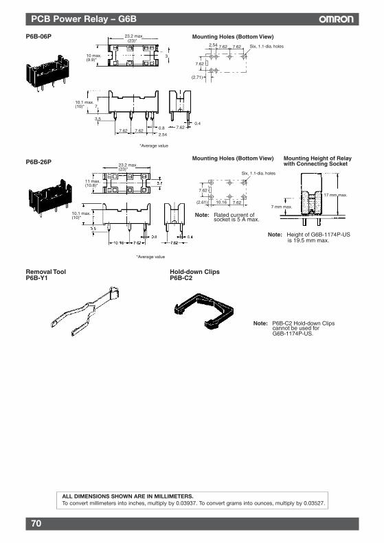
70
PCB Power Relay – G6B
Mounting Height of Relay with Connecting Socket
P6B-06P 23.2 max.
310 max.(9.9)*
10.1 max.(10)* 7
3.5
7.62 7.620.8
2.54
7.620.4
7 mm max.
17 mm max.
7.62
7.62 7.62
(2.71)
2.54 Six, 1.1-dia. holes
Removal ToolP6B-Y1
Hold-down ClipsP6B-C2
(23)*
*Average value
Mounting Holes (Bottom View)
P6B-26PMounting Holes (Bottom View)
Note: Height of G6B-1174P-US is 19.5 mm max.
Note: P6B-C2 Hold-down Clips cannot be used for G6B-1174P-US.
Six, 1.1-dia. holes
11 max.(10.8)*
23.2 max.(23)*
10.1 max.(10)*
*Average value
7.62
(2.61) 10.16 7.62
Note: Rated current of socket is 5 A max.
ALL DIMENSIONS SHOWN ARE IN MILLIMETERS.To convert millimeters into inches, multiply by 0.03937. To convert grams into ounces, multiply by 0.03527.
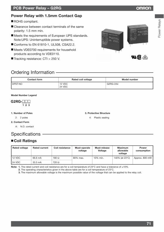
71
PCB Power Relay – G2RG
Model Number Legend
1. Number of Poles 3. Protective Structure
2: 2 poles 4: Plastic sealing
2. Contact Form
A: N.O. contact
Ordering Information
Power Relay with 1.5mm Contact Gap ROHS compliant.
Clearance between contact terminals of the samepolarity: 1.5 mm min.
Meets the requirements of European UPS standards.Note:UPS: Uninterruptible power systems.
Conforms to EN 61810-1, UL508, CSA22.2.
Meets VDE0700 requirements for householdproducts according to VDE0110.
Tracking resistance: CTI > 250 V.
Contact form Rated coil voltage Model number
DPST-NO 12 VDC G2RG-2A424 VDC
Rated voltage Rated current Coil resistance Must-operate Must-release Maximum Powervoltage Voltage allowable consumption
voltage
12 VDC 66.6 mA 180 Ω 80% max. 10% min. 140% (at 23°C) Approx. 800 mW
24 VDC 33.3 mA 720 Ω
Specifications Coil Ratings
Note: 1. The rated current and coil resistance are for a coil temperature of 23°C and have a tolerance of ±10%.2. The operating characteristics given in the above table are for a coil temperature of 23°C.3. The maximum allowable voltage is the maximum possible value of the voltage that can be applied to the relay coil.
Pow
er R
elay
s
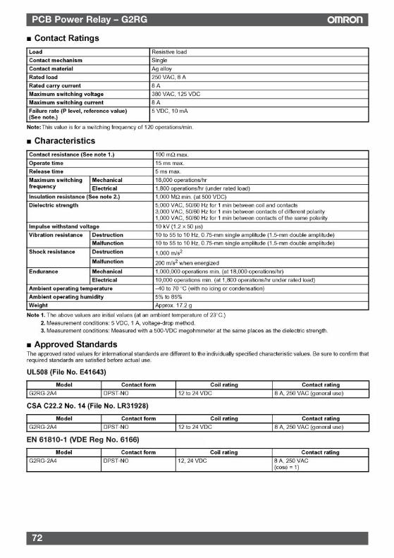
72
PCB Power Relay – G2RG
EN 61810-1 (VDE Reg No. 6166)
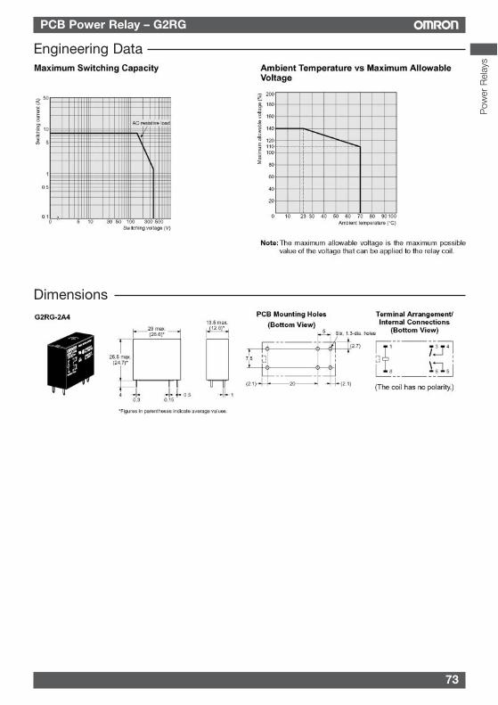
73
PCB Power Relay – G2RG
Engineering Data
Dimensions
Pow
er R
elay
s
74
PCB Power Relay – G2RG
Precautions Correct UseDifferences with the G2RThe G2RG-2A4 has the same terminal arrangement as theG2R-2A4 but the switching capacity and electrical endurance aredifferent. Confirm that correct operation is possible in the actualoperating conditions before using in applications.
ALL DIMENSIONS SHOWN ARE IN MILLIMETERS.To convert millimeters into inches, multiply by 0.03937. To convert grams into ounces, multiply by 0.03527.
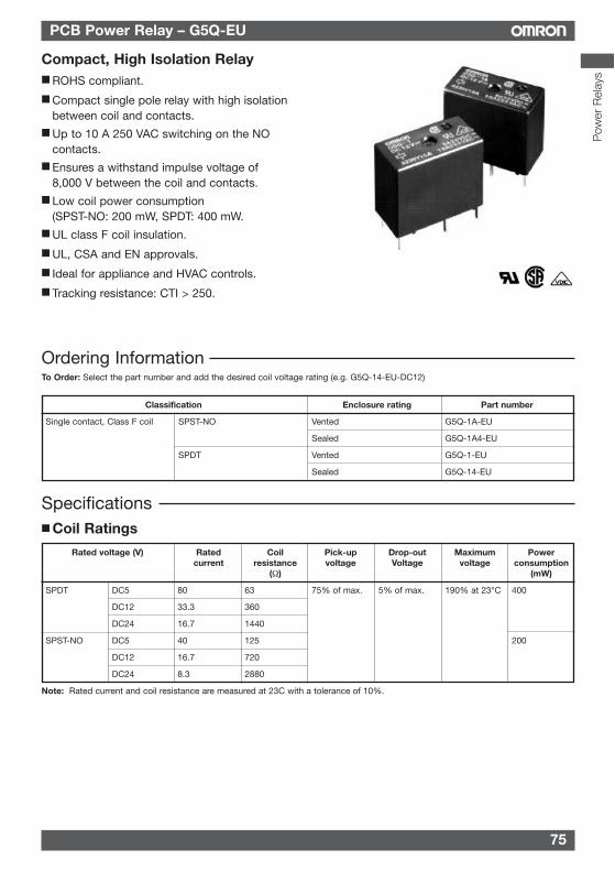
75
PCB Power Relay – G5Q-EU
Pow
er R
elay
s
Ordering Information
Compact, High Isolation Relay ROHS compliant.
Compact single pole relay with high isolationbetween coil and contacts.
Up to 10 A 250 VAC switching on the NOcontacts.
Ensures a withstand impulse voltage of8,000 V between the coil and contacts.
Low coil power consumption(SPST-NO: 200 mW, SPDT: 400 mW.
UL class F coil insulation.
UL, CSA and EN approvals.
Ideal for appliance and HVAC controls.
Tracking resistance: CTI > 250.
Specifications Coil Ratings
Classification Enclosure rating Part number
Single contact, Class F coil SPST-NO Vented G5Q-1A-EU
Sealed G5Q-1A4-EU
SPDT Vented G5Q-1-EU
Sealed G5Q-14-EU
Rated voltage (V) Rated Coil Pick-up Drop-out Maximum Powercurrent resistance voltage Voltage voltage consumption
(Ω) (mW)
SPDT DC5 80 63 75% of max. 5% of max. 190% at 23°C 400
DC12 33.3 360
DC24 16.7 1440
SPST-NO DC5 40 125 200
DC12 16.7 720
DC24 8.3 2880
Note: Rated current and coil resistance are measured at 23C with a tolerance of 10%.
To Order: Select the part number and add the desired coil voltage rating (e.g. G5Q-14-EU-DC12)
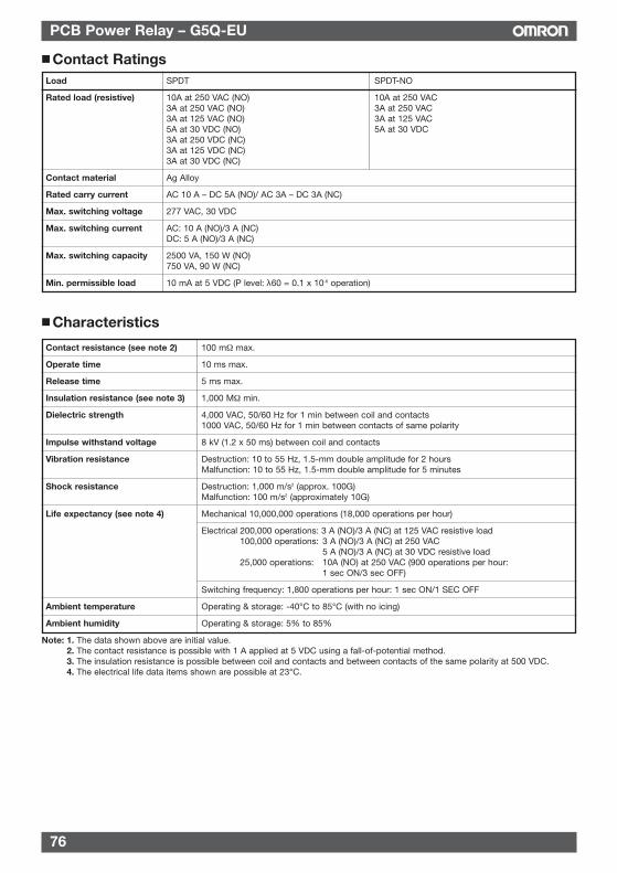
76
PCB Power Relay – G5Q-EU
Contact RatingsLoad SPDT SPDT-NO
Rated load (resistive) 10A at 250 VAC (NO) 10A at 250 VAC3A at 250 VAC (NO) 3A at 250 VAC3A at 125 VAC (NO) 3A at 125 VAC5A at 30 VDC (NO) 5A at 30 VDC3A at 250 VDC (NC)3A at 125 VDC (NC)3A at 30 VDC (NC)
Contact material Ag Alloy
Rated carry current AC 10 A – DC 5A (NO)/ AC 3A – DC 3A (NC)
Max. switching voltage 277 VAC, 30 VDC
Max. switching current AC: 10 A (NO)/3 A (NC)DC: 5 A (NO)/3 A (NC)
Max. switching capacity 2500 VA, 150 W (NO)750 VA, 90 W (NC)
Min. permissible load 10 mA at 5 VDC (P level: λ60 = 0.1 x 10⁻⁶ operation)
Characteristics
Contact resistance (see note 2) 100 mΩ max.
Operate time 10 ms max.
Release time 5 ms max.
Insulation resistance (see note 3) 1,000 MΩ min.
Dielectric strength 4,000 VAC, 50/60 Hz for 1 min between coil and contacts1000 VAC, 50/60 Hz for 1 min between contacts of same polarity
Impulse withstand voltage 8 kV (1.2 x 50 ms) between coil and contacts
Vibration resistance Destruction: 10 to 55 Hz, 1.5-mm double amplitude for 2 hoursMalfunction: 10 to 55 Hz, 1.5-mm double amplitude for 5 minutes
Shock resistance Destruction: 1,000 m/s2 (approx. 100G)Malfunction: 100 m/s2 (approximately 10G)
Life expectancy (see note 4) Mechanical 10,000,000 operations (18,000 operations per hour)
Electrical 200,000 operations: 3 A (NO)/3 A (NC) at 125 VAC resistive load100,000 operations: 3 A (NO)/3 A (NC) at 250 VAC
5 A (NO)/3 A (NC) at 30 VDC resistive load25,000 operations: 10A (NO) at 250 VAC (900 operations per hour:
1 sec ON/3 sec OFF)
Switching frequency: 1,800 operations per hour: 1 sec ON/1 SEC OFF
Ambient temperature Operating & storage: -40°C to 85°C (with no icing)
Ambient humidity Operating & storage: 5% to 85%
Note: 1. The data shown above are initial value.2. The contact resistance is possible with 1 A applied at 5 VDC using a fall-of-potential method.3. The insulation resistance is possible between coil and contacts and between contacts of the same polarity at 500 VDC.4. The electrical life data items shown are possible at 23°C.
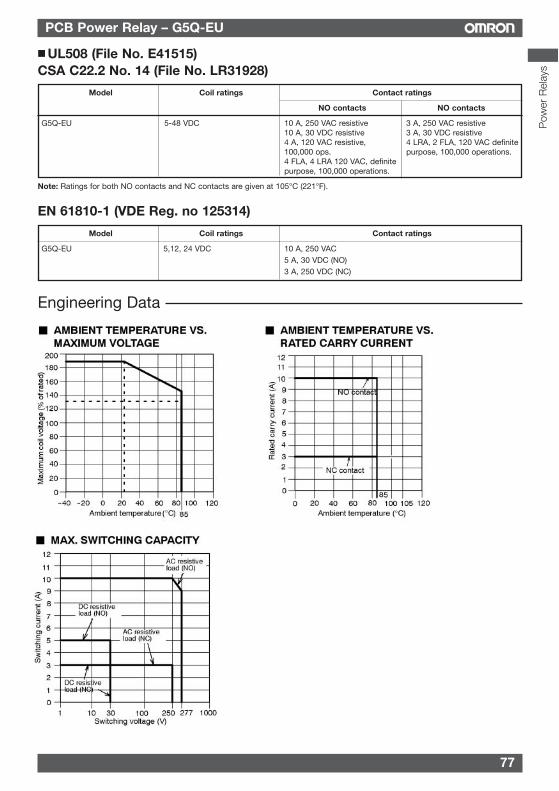
77
PCB Power Relay – G5Q-EU
UL508 (File No. E41515)CSA C22.2 No. 14 (File No. LR31928)
Model Coil ratings Contact ratings
NO contacts NO contacts
G5Q-EU 5-48 VDC 10 A, 250 VAC resistive 3 A, 250 VAC resistive10 A, 30 VDC resistive 3 A, 30 VDC resistive4 A, 120 VAC resistive, 4 LRA, 2 FLA, 120 VAC definite100,000 ops. purpose, 100,000 operations.4 FLA, 4 LRA 120 VAC, definitepurpose, 100,000 operations.
Note: Ratings for both NO contacts and NC contacts are given at 105°C (221°F).
EN 61810-1 (VDE Reg. no 125314)
Model Coil ratings Contact ratings
G5Q-EU 5,12, 24 VDC 10 A, 250 VAC5 A, 30 VDC (NO)3 A, 250 VDC (NC)
Engineering Data
Pow
er R
elay
s
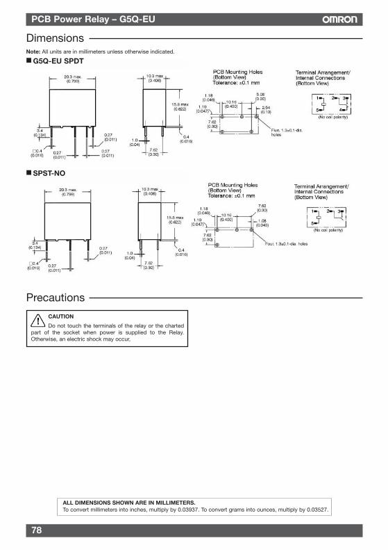
78
PCB Power Relay – G5Q-EU
Precautions
DimensionsNote: All units are in millimeters unless otherwise indicated.
CAUTION
Do not touch the terminals of the relay or the chartedpart of the socket when power is supplied to the Relay.Otherwise, an electric shock may occur,
G5Q-EU SPDT
SPST-NO
ALL DIMENSIONS SHOWN ARE IN MILLIMETERS.To convert millimeters into inches, multiply by 0.03937. To convert grams into ounces, multiply by 0.03527.
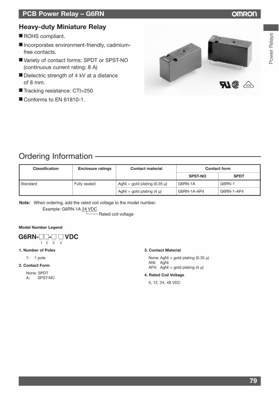
79
PCB Power Relay – G6RN
Ordering Information
Heavy-duty Miniature Relay ROHS compliant.
Incorporates environment-friendly, cadmium-free contacts.
Variety of contact forms: SPDT or SPST-NO(continuous current rating: 8 A)
Dielectric strength of 4 kV at a distanceof 8 mm.
Tracking resistance: CTI>250
Conforms to EN 61810-1.
Rated coil voltage
Note: When ordering, add the rated coil voltage to the model number.
Example: G6RN-1A 24 VDC
Classification Enclosure ratings Contact material Contact form
SPST-NO SPDT
Standard Fully sealed AgNi + gold plating (0.35 µ) G6RN-1A G6RN-1
AgNi + gold plating (4 µ) G6RN-1A-AP4 G6RN-1-AP4
Model Number Legend
1. Number of Poles
1: 1 pole
2. Contact Form
None: SPDTA: SPST-NO
3. Contact Material
None: AgNi + gold plating (0.35 µ)ANI: AgNiAP4: AgNi + gold plating (4 µ)
4. Rated Coil Voltage
5, 12, 24, 48 VDC
Pow
er R
elay
s
VDE
G6RN-- VDC1 2 3 4
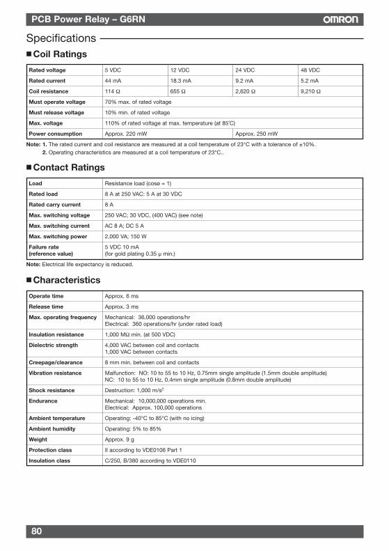
80
PCB Power Relay – G6RN
Coil Ratings
Rated voltage 5 VDC 12 VDC 24 VDC 48 VDC
Rated current 44 mA 18.3 mA 9.2 mA 5.2 mA
Coil resistance 114 Ω 655 Ω 2,620 Ω 9,210 Ω
Must operate voltage 70% max. of rated voltage
Must release voltage 10% min. of rated voltage
Max. voltage 110% of rated voltage at max. temperature (at 85˚C)
Power consumption Approx. 220 mW Approx. 250 mW
Note: 1. The rated current and coil resistance are measured at a coil temperature of 23°C with a tolerance of ±10%.2. Operating characteristics are measured at a coil temperature of 23°C..
Contact Ratings
Load Resistance load (cosø = 1)
Rated load 8 A at 250 VAC: 5 A at 30 VDC
Rated carry current 8 A
Max. switching voltage 250 VAC; 30 VDC, (400 VAC) (see note)
Max. switching current AC 8 A; DC 5 A
Max. switching power 2,000 VA; 150 W
Failure rate 5 VDC 10 mA(reference value) (for gold plating 0.35 µ min.)
Note: Electrical life expectancy is reduced.
Characteristics
Operate time Approx. 6 ms
Release time Approx. 3 ms
Max. operating frequency Mechanical: 36,000 operations/hrElectrical: 360 operations/hr (under rated load)
Insulation resistance 1,000 MΩ min. (at 500 VDC)
Dielectric strength 4,000 VAC between coil and contacts1,000 VAC between contacts
Creepage/clearance 8 mm min. between coil and contacts
Vibration resistance Malfunction: NO: 10 to 55 to 10 Hz, 0.75mm single amplitude (1.5mm double amplitude)NC: 10 to 55 to 10 Hz, 0.4mm single amplitude (0.8mm double amplitude)
Shock resistance Destruction: 1,000 m/s2
Endurance Mechanical: 10,000,000 operations min.Electrical: Approx. 100,000 operations
Ambient temperature Operating: -40°C to 85°C (with no icing)
Ambient humidity Operating: 5% to 85%
Weight Approx. 9 g
Protection class II according to VDE0106 Part 1
Insulation class C/250, B/380 according to VDE0110
Specifications
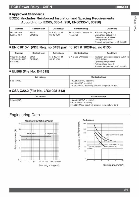
81
PCB Power Relay – G6RN
Standard Contact form Coil ratings Contact rating Conditions
VDE0435 Part201 SPDT 5, 6, 12, 18, 24 8 A at 250 VAC (cosø = 1) Insulation group according to VDE0110VDE0435 Part120 SPST-NO 36, 48 VDC C/250, B/380EN 61810 Operating range: class 1
Pick-up class: class CAmbient temperature: -40˚C to 85˚C
Engineering DataMaximum Switching Power
Sw
itchi
ng c
urre
nt (
A)
Switching Voltage (V)
5 10 30 50 100 300 500 10000.1
1
5
10
50
100
DC resistive load AC resistive load
1
Endurance
End
uran
ce (
x 10
3 op
erat
ions
)
Switching Current (A)
1000
100
500
300
100
50
30
2 4 6 8 10
30 VDC resistive load
250 VAC resistive load
250 VAC inductionload (cosf=0.4)
Approved StandardsEC255 (Includes Reinforced Insulation and Spacing Requirements
According to IEC65, 335-1, 950, EN60335-1, 60950)
Standard Contact form Coil ratings Contact rating Conditions
IEC255-1-00 SPDT 5, 6, 12, 18, 24 8A at 250 VAC (cosø = 1) Pollution: degree: 3I IEC255-0-20 SPST-NO 36, 48 VDC (see note) Overvoltage category: II
Operating range: class 1Pick-up class: class CAmbient temperature: -40˚C to 85˚C
EN 61810-1 (VDE Reg. no 0435 part no 201 & 102/Reg. no 6135)
Coil ratings Contact ratings
5 to 48 VDC 10 A at 250 VAC (resistive)5 A at 30 VDC (resistive)8 A at 250 VAC (resistive) (ambient temperature: 85˚C)
UL508 (File No. E41515)
Coil ratings Contact ratings
5 to 48 VDC 10 A at 250 VAC (resistive)5 A at 30 VDC (resistive)8 A at 250 VAC (resistive) (ambient temperature: 85˚C)
CSA C22.2 (File No. LR31928-543)
Pow
er R
elay
s
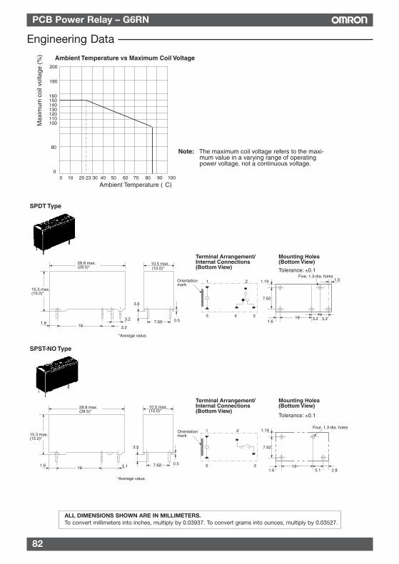
82
PCB Power Relay – G6RN
Engineering Data
Ambient Temperature vs Maximum Coil Voltage
Max
imum
coi
l vol
tage
(%
)
Ambient Temperature (°C)
200
180
160 150 140 130 120 110 100
80
00 10 20 23 30 40 50 60 70 80 90 100
Note: The maximum coil voltage refers to the maxi-mum value in a varying range of operating power voltage, not a continuous voltage.
3.219
Five, 1.3-dia. holes
7.62
3.2
1.19
1.6
1.5
28.8 max.(28.5)*
197.62
3.5
0.55.11.6
15.3 max.(15.0)*
10.5 max.(10.0)*
*Average value.
15.3 max.(15.0)*
28.8 max.(28.5)*
19
3.2
10.5 max.(10.0)*
7.62
3.5
0.5
3.21.6
SPDT Type
Terminal Arrangement/Internal Connections (Bottom View)
Mounting Holes(Bottom View)
Tolerance: ±0.1
1 2
5 4 3
Orientation mark
SPST-NO Type
1 2
5 3
Orientation mark
Terminal Arrangement/Internal Connections(Bottom View)
Mounting Holes(Bottom View)
Tolerance: ±0.1
19
Four, 1.3-dia. holes
5.1
7.62
1.19
1.6 2.8
*Average value.
ALL DIMENSIONS SHOWN ARE IN MILLIMETERS.To convert millimeters into inches, multiply by 0.03937. To convert grams into ounces, multiply by 0.03527.
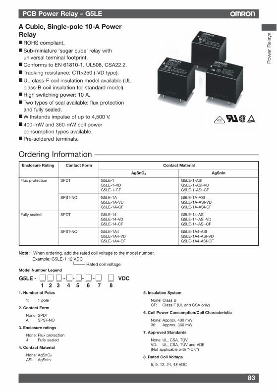
83
PCB Power Relay – G5LE
Pow
er R
elay
s
A Cubic, Single-pole 10-A PowerRelay ROHS compliant. Sub-miniature ‘sugar cube’ relay with
universal terminal footprint. Conforms to EN 61810-1, UL508, CSA22.2. Tracking resistance: CTI>250 (-VD type). UL class-F coil insulation model available (UL
class-B coil insulation for standard model). High switching power: 10 A. Two types of seal available; flux protection
and fully sealed. Withstands impulse of up to 4,500 V. 400-mW and 360-mW coil power
consumption types available. Pre-soldered terminals.
VDE
Rated coil voltage
Note: When ordering, add the rated coil voltage to the model number.Example: G5LE-1 12 VDC
Model Number Legend
1. Number of Poles
1: 1 pole
2. Contact Form
None: SPDTA: SPST-NO
3. Enclosure ratings
None: Flux protection4: Fully sealed
4. Contact Material
None: AgSnO2
ASI: AgSnIn
5. Insulation System
None: Class BCF: Class F (UL and CSA only)
6. Coil Power Consumption/Coil Characteristic
None: Approx. 400 mW36: Approx. 360 mW
7. Approved Standards
None: UL, CSA, TÜVVD: UL, CSA, TÜV and VDE(Not applicable with “-CF.”)
8. Rated Coil Voltage
5, 9, 12, 24, 48 VDC
G5LE - - - - - VDC1 2 3 4 5 6 7 8
Ordering InformationEnclosure Rating Contact Form Contact Material
AgSnO2 AgSnIn
Flux protection SPDT G5LE-1 G5LE-1-ASIG5LE-1-VD G5LE-1-ASI-VDG5LE-1-CF G5LE-1-ASI-CF
SPST-NO G5LE-1A G5LE-1A-ASIG5LE-1A-VD G5LE-1A-ASI-VDG5LE-1A-CF G5LE-1A-ASI-CF
Fully sealed SPDT G5LE-14 G5LE-14-ASIG5LE-14-VD G5LE-14-ASI-VDG5LE-14-CF G5LE-14-ASI-CF
SPST-NO G5LE-1A4 G5LE-1A4-ASIG5LE-1A4-VD G5LE-1A4-ASI-VDG5LE-1A4-CF G5LE-1A4-ASI-CF
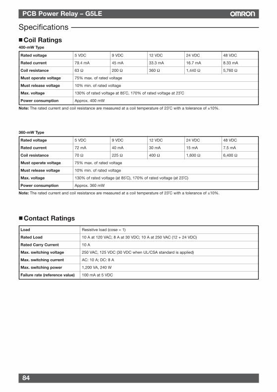
84
PCB Power Relay – G5LE
Specifications
Contact Ratings
Coil Ratings400-mW Type
Rated voltage 5 VDC 9 VDC 12 VDC 24 VDC 48 VDC
Rated current 79.4 mA 45 mA 33.3 mA 16.7 mA 8.33 mA
Coil resistance 63 Ω 200 Ω 360 Ω 1,440 Ω 5,760 Ω
Must operate voltage 75% max. of rated voltage
Must release voltage 10% min. of rated voltage
Max. voltage 130% of rated voltage at 85˚C, 170% of rated voltage at 23˚C
Power consumption Approx. 400 mW
Note: The rated current and coil resistance are measured at a coil temperature of 23˚C with a tolerance of ±10%.
360-mW Type
Rated voltage 5 VDC 9 VDC 12 VDC 24 VDC 48 VDC
Rated current 72 mA 40 mA 30 mA 15 mA 7.5 mA
Coil resistance 70 Ω 225 Ω 400 Ω 1,600 Ω 6,400 Ω
Must operate voltage 75% max. of rated voltage
Must release voltage 10% min. of rated voltage
Max. voltage 130% of rated voltage (at 85˚C), 170% of rated voltage (at 23˚C)
Power consumption Approx. 360 mW
Note: The rated current and coil resistance are measured at a coil temperature of 23˚C with a tolerance of ±10%.
Load Resistive load (cosø = 1)
Rated Load 10 A at 120 VAC; 8 A at 30 VDC; 10 A at 250 VAC (12 + 24 VDC)
Rated Carry Current 10 A
Max. switching voltage 250 VAC, 125 VDC (30 VDC when UL/CSA standard is applied)
Max. switching current AC: 10 A; DC: 8 A
Max. switching power 1,200 VA, 240 W
Failure rate (reference value) 100 mA at 5 VDC
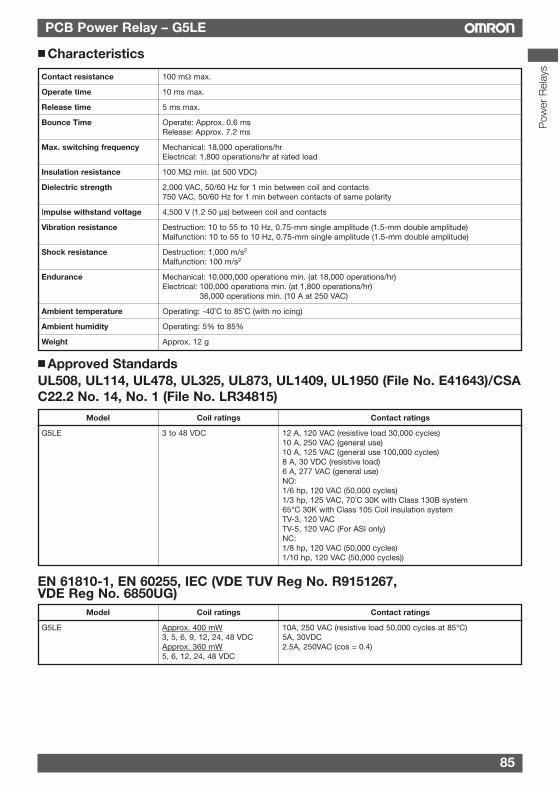
85
PCB Power Relay – G5LE
Pow
er R
elay
s
Model Coil ratings Contact ratings
G5LE 3 to 48 VDC 12 A, 120 VAC (resistive load 30,000 cycles)10 A, 250 VAC (general use)10 A, 125 VAC (general use 100,000 cycles)8 A, 30 VDC (resistive load)6 A, 277 VAC (general use)NO:1/6 hp, 120 VAC (50,000 cycles)1/3 hp, 125 VAC, 70˚C 30K with Class 130B system65°C 30K with Class 105 Coil insulation systemTV-3, 120 VACTV-5, 120 VAC (For ASI only) NC:1/8 hp, 120 VAC (50,000 cycles)1/10 hp, 120 VAC (50,000 cycles))
Approved StandardsUL508, UL114, UL478, UL325, UL873, UL1409, UL1950 (File No. E41643)/CSAC22.2 No. 14, No. 1 (File No. LR34815)
Characteristics
Contact resistance 100 mΩ max.
Operate time 10 ms max.
Release time 5 ms max.
Bounce Time Operate: Approx. 0.6 msRelease: Approx. 7.2 ms
Max. switching frequency Mechanical: 18,000 operations/hrElectrical: 1,800 operations/hr at rated load
Insulation resistance 100 MΩ min. (at 500 VDC)
Dielectric strength 2,000 VAC, 50/60 Hz for 1 min between coil and contacts750 VAC, 50/60 Hz for 1 min between contacts of same polarity
Impulse withstand voltage 4,500 V (1.2 50 µs) between coil and contacts
Vibration resistance Destruction: 10 to 55 to 10 Hz, 0.75-mm single amplitude (1.5-mm double amplitude)Malfunction: 10 to 55 to 10 Hz, 0.75-mm single amplitude (1.5-mm double amplitude)
Shock resistance Destruction: 1,000 m/s2
Malfunction: 100 m/s2
Endurance Mechanical: 10,000,000 operations min. (at 18,000 operations/hr)Electrical: 100,000 operations min. (at 1,800 operations/hr)
36,000 operations min. (10 A at 250 VAC)
Ambient temperature Operating: -40˚C to 85˚C (with no icing)
Ambient humidity Operating: 5% to 85%
Weight Approx. 12 g
EN 61810-1, EN 60255, IEC (VDE TUV Reg No. R9151267,VDE Reg No. 6850UG)
Model Coil ratings Contact ratings
G5LE Approx. 400 mW 10A, 250 VAC (resistive load 50,000 cycles at 85°C)3, 5, 6, 9, 12, 24, 48 VDC 5A, 30VDCApprox. 360 mW 2.5A, 250VAC (cos = 0.4)5, 6, 12, 24, 48 VDC
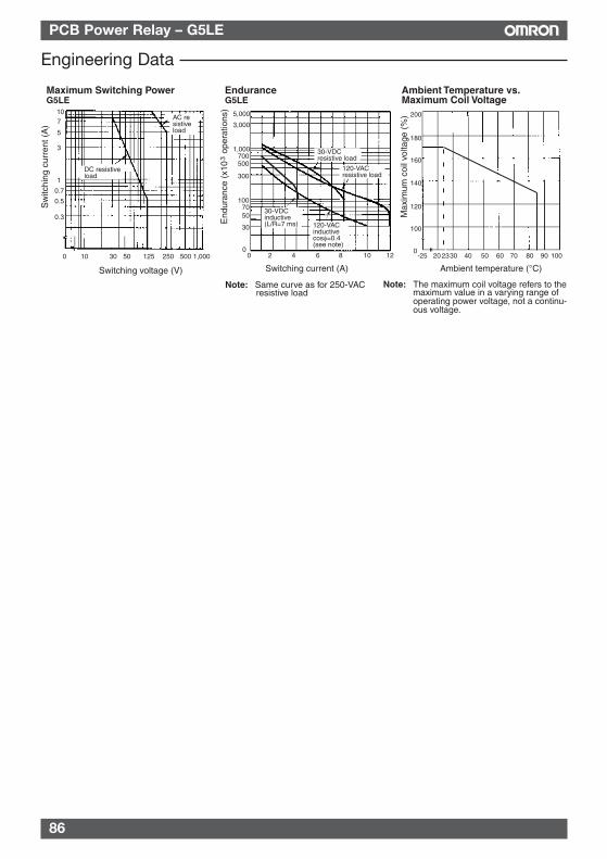
86
PCB Power Relay – G5LE
Engineering Data
Maximum Switching PowerG5LE
Ambient Temperature vs. Maximum Coil Voltage
Max
imum
coi
l vol
tage
(%
)
Ambient temperature (°C)Switching voltage (V)
EnduranceG5LE
End
uran
ce (
x10
ope
ratio
ns)
3
Switching current (A)
Sw
itchi
ng c
urre
nt (
A)
AC resistiveload
DC resistiveload
23
30-VDCresistive load
120-VACresistive load
30-VDCinductive (L/R=7 ms) 120-VAC
inductive cosφ=0.4 (see note)
2 4 6 8 10 12
Note: Same curve as for 250-VAC resistive load
200
180
160
140
120
100
0-25 20 30 40 50 60 70 80 90 100
107
5
3
1
0.7
0.5
0.3
0 10 30 50 125 250 500 1,000
5,000
3,000
1,000700500
30
0
300
1007050
0
Note: The maximum coil voltage refers to the maximum value in a varying range of operating power voltage, not a continu-ous voltage.
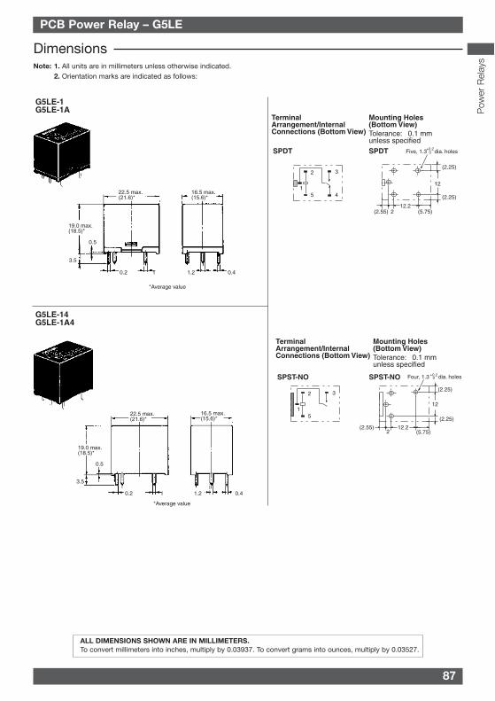
87
TextPCB Power Relay – G5LE
Pow
er R
elay
s
ALL DIMENSIONS SHOWN ARE IN MILLIMETERS.To convert millimeters into inches, multiply by 0.03937. To convert grams into ounces, multiply by 0.03527.
DimensionsNote: 1. All units are in millimeters unless otherwise indicated.
2. Orientation marks are indicated as follows:
G5LE-14G5LE-1A4
22.5 max. (21.6)*
16.5 max. (15.6)*
19.0 max. (18.5)*
0.5
3.5
0.2 1 1.2 0.4
Terminal Arrangement/Internal Connections (Bottom View)
Mounting Holes(Bottom View)
SPDT
Tolerance: ±0.1 mm unless specifiedSPDT
12.2
12
2(2.55)
(2.25)
Five, 1.3 dia. holes+0.20
(5.75)
(2.25)
1
2
5
3
4
G5LE-1G5LE-1A
*Average value
22.5 max. (21.6)*
19.0 max. (18.5)*
0.5
3.5
0.2 1
16.5 max. (15.6)*
1.2 0.4
Terminal Arrangement/Internal Connections (Bottom View)
Mounting Holes(Bottom View)
SPST-NO
Tolerance: ±0.1 mm unless specified
1
2
5
3
*Average value
SPST-NO
12.2
12
2(2.55)
(2.25)
(5.75)
Four, 1.3 dia. holes+0.20
(2.25)
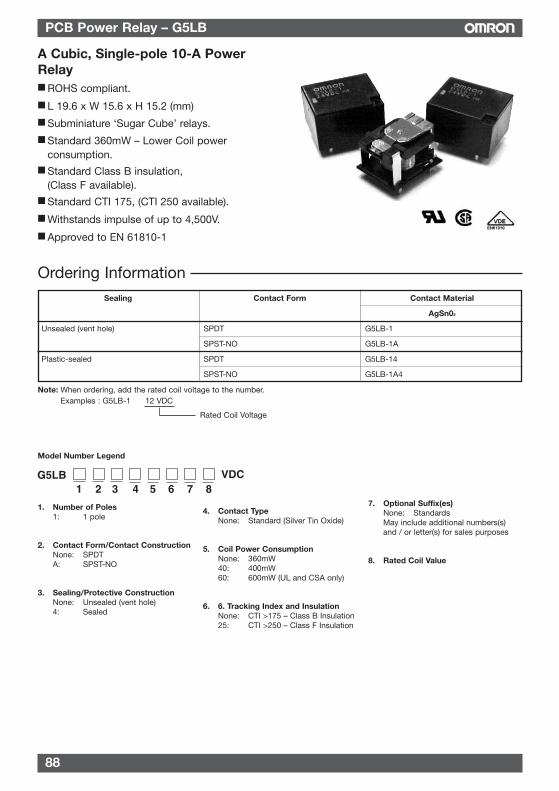
88
PCB Power Relay – G5LB
A Cubic, Single-pole 10-A PowerRelay ROHS compliant.
L 19.6 x W 15.6 x H 15.2 (mm)
Subminiature ‘Sugar Cube’ relays.
Standard 360mW – Lower Coil powerconsumption.
Standard Class B insulation,(Class F available).
Standard CTI 175, (CTI 250 available).
Withstands impulse of up to 4,500V.
Approved to EN 61810-1
Sealing Contact Form Contact Material
AgSn02
Unsealed (vent hole) SPDT G5LB-1
SPST-NO G5LB-1A
Plastic-sealed SPDT G5LB-14
SPST-NO G5LB-1A4
Ordering Information
Note: When ordering, add the rated coil voltage to the number.Examples : G5LB-1 12 VDC
Rated Coil Voltage
Model Number Legend
1. Number of Poles1: 1 pole
2. Contact Form/Contact ConstructionNone: SPDTA: SPST-NO
3. Sealing/Protective ConstructionNone: Unsealed (vent hole)4: Sealed
4. Contact TypeNone: Standard (Silver Tin Oxide)
5. Coil Power ConsumptionNone: 360mW40: 400mW60: 600mW (UL and CSA only)
6. 6. Tracking Index and InsulationNone: CTI >175 – Class B Insulation25: CTI >250 – Class F Insulation
7. Optional Suffix(es)None: StandardsMay include additional numbers(s)and / or letter(s) for sales purposes
8. Rated Coil Value
G5LB VDC1 2 3 4 5 6 7 8
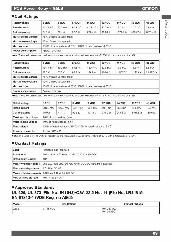
89
PCB Power Relay – G5LB
Pow
er R
elay
s
Rated voltage 3 VDC 5 VDC 6 VDC 9 VDC 12 VDC 24 VDC 36 VDC 48 VDC
Rated current 123.3 mA 72.0 mA 60.8 mA 40.8 mA 30.7 mA 15.2 mA 10.2 mA 7.6 mA
Coil resistance 24.3 Ω 69.4 Ω 98.7 Ω 220.4 Ω 390.6 Ω 1575.4 Ω 3533.7 Ω 6287.4 Ω
Must operate voltage 75% of rated voltage (max.)
Must release voltage 10% of rated voltage (min.)
Max. voltage 130% of rated voltage at 85°C, 170% of rated voltage at 23°C
Power consumption Approx. 360 mW
Note: The rated current and coil resistance are measured at a coil temperature of 23°C with a tolerance of ±10%.
Coil Ratings
Contact Ratings
Rated voltage 3 VDC 5 VDC 6 VDC 9 VDC 12 VDC 24 VDC 36 VDC 48 VDC
Rated current 136.4 mA 80.0 mA 67.8 mA 45.7 mA 32.8 mA 17.0 mA 11.3 mA 8.5 mA
Coil resistance 22.0 Ω 62.5 Ω 88.5 Ω 196.9 Ω 366.0 Ω 1,407.7 Ω 3,196.8 Ω 5,638.0 Ω
Must operate voltage 75% of rated voltage (max.)
Must release voltage 10% of rated voltage (min.)
Max. voltage 130% of rated voltage at 85°C, 170% of rated voltage at 23°C
Power consumption Approx. 400 mW
Note: The rated current and coil resistance are measured at a coil temperature of 23°C with a tolerance of ±10%.
Load Resistive load (cos Ø=1)
Rated load 10A at 120 VAC, 8A at 30 VDC & 10A at 250 VAC
Rated carry current 10A
Max. switching voltage 250 VAC, 125 VDC (30 VDC when UL/CSA standard is applied)
Max. switching current AC: 10A; DC: 8A
Max. switching capacity 1,200 VA, 240 W & 2,500 VA
Min. permissible load 100 mA at 5 VDC
Approved StandardsUL 325, UL 873 (File No. E41643)/CSA 22.2 No. 14 (File No. LR34815)EN 61810-1 (VDE Reg. no A662)Model Coil Ratings Contact Ratings
G5LB 3 - 48 VDC 10A 250 VAC10A 30 VDC
Rated voltage 3 VDC 5 VDC 6 VDC 9 VDC 12 VDC 24 VDC 36 VDC 48 VDC
Rated current 200.2 mA 120.0 mA 100.7 mA 66.8 mA 50.4 mA 25.3 mA 16.6 mA 12.6 mA
Coil resistance 15.0Ω 41.7 Ω 59.6 Ω 134.8 Ω 237.9 Ω 947.6 Ω 2164.8 Ω 3800.0 Ω
Must operate voltage 75% of rated voltage (max.)
Must release voltage 10% of rated voltage (min.)
Max. voltage 130% of rated voltage at 85°C, 170% of rated voltage at 23°C
Power consumption Approx. 600 mW
Note: The rated current and coil resistance are measured at a coil temperature of 23°C with a tolerance of ±10%.
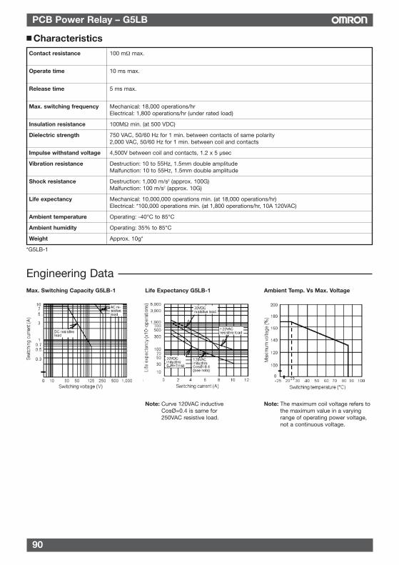
90
PCB Power Relay – G5LB
CharacteristicsContact resistance 100 mΩ max.
Operate time 10 ms max.
Release time 5 ms max.
Max. switching frequency Mechanical: 18,000 operations/hrElectrical: 1,800 operations/hr (under rated load)
Insulation resistance 100MΩ min. (at 500 VDC)
Dielectric strength 750 VAC, 50/60 Hz for 1 min. between contacts of same polarity2,000 VAC, 50/60 Hz for 1 min. between coil and contacts
Impulse withstand voltage 4,500V between coil and contacts, 1.2 x 5 µsec
Vibration resistance Destruction: 10 to 55Hz, 1.5mm double amplitudeMalfunction: 10 to 55Hz, 1.5mm double amplitude
Shock resistance Destruction: 1,000 m/s2 (approx. 100G)Malfunction: 100 m/s2 (approx. 10G)
Life expectancy Mechanical: 10,000,000 operations min. (at 18,000 operations/hr)Electrical: *100,000 operations min. (at 1,800 operations/hr, 10A 120VAC)
Ambient temperature Operating: -40°C to 85°C
Ambient humidity Operating: 35% to 85°C
Weight Approx. 10g*
*G5LB-1
Engineering Data
Note: Curve 120VAC inductiveCosØ=0.4 is same for250VAC resistive load.
Note: The maximum coil voltage refers tothe maximum value in a varyingrange of operating power voltage,not a continuous voltage.
Max. Switching Capacity G5LB-1 Life Expectancy G5LB-1 Ambient Temp. Vs Max. Voltage
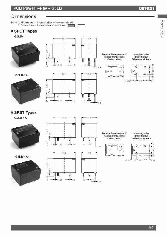
91
PCB Power Relay – G5LB
Pow
er R
elay
s
DimensionsNote: 1. All units are milimeters unless otherwise indiated
2. Orientation marks are indicated as follow:
SPDT TypesG5LB-1
G5LB-14
Terminal Arrangemment/Internal Connections
(Bottom View)
Mounting Holes(Bottom View)
Tolerance: ±0.1mm
Terminal Arrangemment/Internal Connections
(Bottom View)
Mounting Holes(Bottom View)
Tolerance: ±0.1mm
SPST TypesG5LB-1A
G5LB-1A4
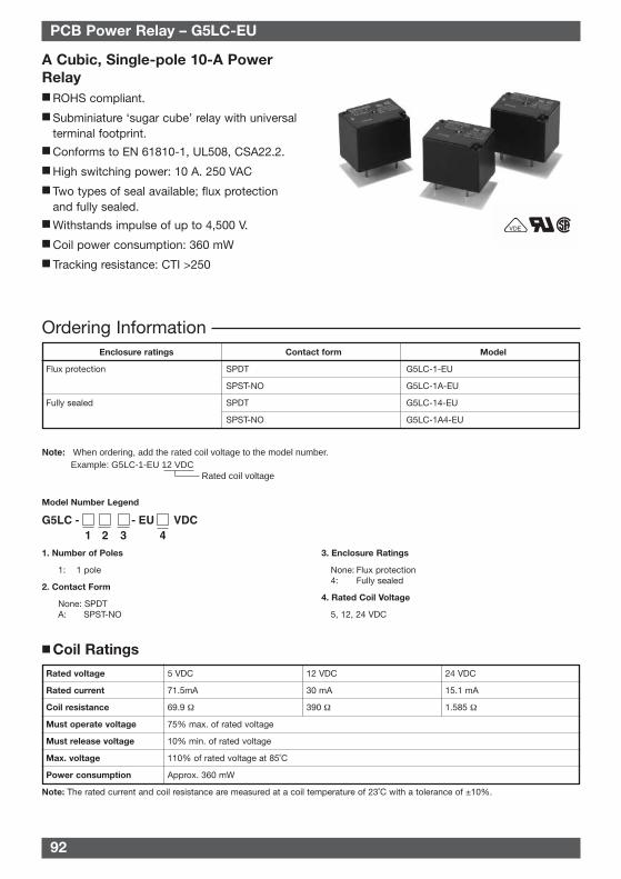
92
A Cubic, Single-pole 10-A PowerRelay ROHS compliant.
Subminiature ‘sugar cube’ relay with universalterminal footprint.
Conforms to EN 61810-1, UL508, CSA22.2.
High switching power: 10 A. 250 VAC
Two types of seal available; flux protectionand fully sealed.
Withstands impulse of up to 4,500 V.
Coil power consumption: 360 mW
Tracking resistance: CTI >250
VDE
Ordering Information
Rated coil voltage
Note: When ordering, add the rated coil voltage to the model number.Example: G5LC-1-EU 12 VDC
Enclosure ratings Contact form Model
Flux protection SPDT G5LC-1-EU
SPST-NO G5LC-1A-EU
Fully sealed SPDT G5LC-14-EU
SPST-NO G5LC-1A4-EU
Model Number Legend
1. Number of Poles
1: 1 pole
2. Contact Form
None: SPDTA: SPST-NO
3. Enclosure Ratings
None: Flux protection4: Fully sealed
4. Rated Coil Voltage
5, 12, 24 VDC
Coil Ratings
Rated voltage 5 VDC 12 VDC 24 VDC
Rated current 71.5mA 30 mA 15.1 mA
Coil resistance 69.9 Ω 390 Ω 1.585 Ω
Must operate voltage 75% max. of rated voltage
Must release voltage 10% min. of rated voltage
Max. voltage 110% of rated voltage at 85˚C
Power consumption Approx. 360 mW
Note: The rated current and coil resistance are measured at a coil temperature of 23˚C with a tolerance of ±10%.
PCB Power Relay – G5LC-EU
G5LC -1 2 3 4
VDC- EU
93
PCB Power Relay – G5LC-EU
Contact Ratings
Load Resistive load (cosφ = 1)
Rated Load 10 A at 250 VAC (NO), 12 A at 120 VAC (NO), 5 A at 120 VAC (NO/NC)10 A at 24 VDC (NO), 5 A at 24 VDC (NO/NC)
Rated Carry Current 12 A
Max. switching voltage 250 VAC, 125 VDC (30 VDC when UL/CSA standard is applied)
Max. switching current AC: 12 A; DC: 12 A
Max. switching power 1,200 VA, 240 W
Failure rate (reference value) 100 mA at 5 VDC (P level: λ60 = 0.1 x 10⁻⁶ operation)
Characteristics
Approved Standards
Contact resistance 100 mΩ max.
Operate time 10 ms max.
Release time 5 ms max.
Insulation resistance 1,000 MΩ min. (at 500 VDC)
Dielectric strength 2,000 VAC, 50/60 Hz for 1 min between coil and contacts750 VAC, 50/60 Hz for 1 min between contacts of same polarity
Impulse withstand voltage 4,500 V (1.2 x 50 ms) between coil and contacts
Vibration resistance Destruction: 10 to 55 to 10 Hz, 0.75-mm single amplitude (1.5-mm double amplitude)Malfunction: 10 to 55 to 10 Hz, 0.75-mm single amplitude (1.5-mm double amplitude)
Shock resistance Destruction: 1,000 m/s2
Malfunction: 100 m/s2
Endurance Mechanical: 10,000,000 operations min. (at 36,000 operations/hr)Electrical: 100,000 operations min. (at 1,800 operations/hr)
Ambient temperature Operating: -25˚C to 85˚C (with no icing)
Ambient humidity Operating: 5% to 85%
Weight Approx. 12 g
Model Coil ratings Contact ratings
G5LC-EU 5 to 24 VDC NO: 10 A, 250 VAC (general use)10 A, 24 VDC (resistive load)1/8 hp, 120 VAC (50,000 cycles)12 A, 120 VAC (resistive load)
NC: 1/8 hp, 120 VAC (50,000 cycles)
UL508, UL873 (File No. E41643)/CSA C22.2 No. 14, No. 0 (File No. LR31928)
Model Coil ratings Contact ratings
G5LC-EU Approx. 360 mW 5 A, 250 VAC (NC)5, 12, 24 VDC 10 A, 250 VAC (NO)
EN 61810-1 (VDE Reg. no 40002435)
Pow
er R
elay
s
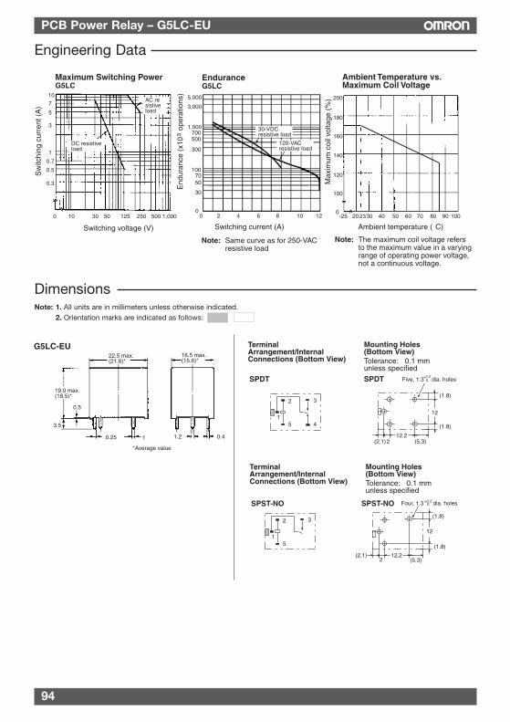
G5LC-EU22.5 max. (21.6)*
16.5 max. (15.6)*
19.0 max. (18.5)*
0.5
3.5
0.25 1 1.2 0.4
Terminal Arrangement/Internal Connections (Bottom View)
Mounting Holes(Bottom View)
SPDT
Tolerance: ±0.1 mm unless specifiedSPDT
12.2
12
2(2.1)
(1.8)
Five, 1.3 dia. holes+0.20
(5.3)
(1.8)
1
2
5
3
4
Terminal Arrangement/Internal Connections (Bottom View)
Mounting Holes(Bottom View)
SPST-NO
Tolerance: ±0.1 mm unless specified
1
2
5
3
*Average value
SPST-NO
12.2
12
2(2.1)
(1.8)
(5.3)
Four, 1.3 dia. holes+0.20
(1.8)
94
PCB Power Relay – G5LC-EU
Engineering Data
Maximum Switching PowerG5LC
Ambient Temperature vs. Maximum Coil Voltage
Max
imum
coi
l vol
tage
(%
)
Ambient temperature (°C)Switching voltage (V)
EnduranceG5LC
End
uran
ce (
x10
ope
ratio
ns)
3
Switching current (A)
Sw
itchi
ng c
urre
nt (
A)
AC resistiveload
DC resistiveload
23
30-VDCresistive load
120-VACresistive load
2 4 6 8 10 12
Note: Same curve as for 250-VAC resistive load
200
180
160
140
120
100
0-25 20 30 40 50 60 70 80 90 100
107
5
3
1
0.7
0.5
0.3
0 10 30 50 125 250 500 1,000
5,000
3,000
1,000700500
30
0
300
1007050
0
Note: The maximum coil voltage refers to the maximum value in a varying range of operating power voltage, not a continuous voltage.
DimensionsNote: 1. All units are in millimeters unless otherwise indicated.
2. Orientation marks are indicated as follows:

95
PCB Power Relay – G5LC-EU
Basic InformationBefore actually committing any component to a mass-productionsituation, OMRON strongly recommends situational testing, in asclose to actual production situations as possible. One reason is toconfirm that the product will still perform as expected aftersurviving the many handling and mounting processes involvedin mass production. Also, even though OMRON relays areindividually tested a number of times, and each meets strictrequirements, a certain testing tolerance is permissible. When ahigh-precision product uses many components, each dependsupon the rated performance thresholds of the other components.Thus, the overall performance tolerance may accumulate intoundesirable levels. To avoid problems, always conduct testsunder the actual application conditions.
GeneralTo maintain the initial characteristics of a relay, exercise care thatit is not dropped or mishandled. For the same reason, do notremove the case of the relay; otherwise, the characteristics maydegrade. Avoid using the relay in an atmosphere containingsulfuric acid (SO2), hydrogen sulfide (H2S), or other corrosivegases. Do not continuously apply a voltage higher than the ratedmaximum voltage to the relay. Never try to operate the relay at avoltage and a current other than those rated. Do not use the relay at temperatures higher than that specified inthe catalog or data sheet.
Precautions
ALL DIMENSIONS SHOWN ARE IN MILLIMETERS.To convert millimeters into inches, multiply by 0.03937. To convert grams into ounces, multiply by 0.03527.
Pow
er R
elay
s
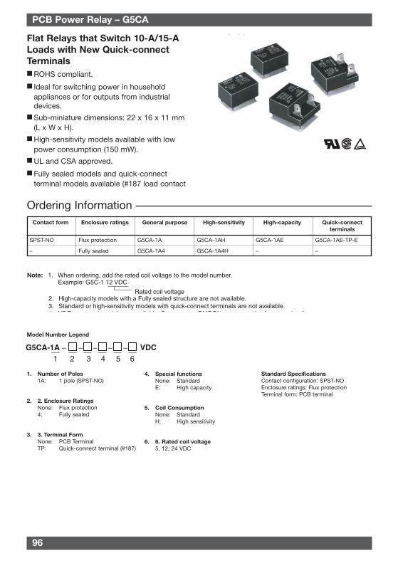
96
Flat Relays that Switch 10-A/15-ALoads with New Quick-connectTerminals ROHS compliant.
Ideal for switching power in householdappliances or for outputs from industrialdevices.
Sub-miniature dimensions: 22 x 16 x 11 mm(L x W x H).
High-sensitivity models available with lowpower consumption (150 mW).
UL and CSA approved.
Fully sealed models and quick-connectterminal models available (#187 load contact
terminals).
Ordering InformationContact form Enclosure ratings General purpose High-sensitivity High-capacity Quick-connect
terminals
SPST-NO Flux protection G5CA-1A G5CA-1AH G5CA-1AE G5CA-1AE-TP-E
– Fully sealed G5CA-1A4 G5CA-1A4H – –
PCB Power Relay – G5CA
Model Number Legend
1. Number of Poles1A: 1 pole (SPST-NO)
2. 2. Enclosure RatingsNone: Flux protection4: Fully sealed
3. 3. Terminal FormNone: PCB TerminalTP: Quick-connect terminal (#187)
4. Special functionsNone: StandardE: High capacity
5. Coil ConsumptionNone: StandardH: High sensitivity
6. 6. Rated coil voltage5, 12, 24 VDC
Standard SpecificationsContact configuration: SPST-NOEnclosure ratings: Flux protectionTerminal form: PCB terminal
G5CA-1A1
–
4
–
32
–
5
–
6
– VDC
Rated coil voltage
Note: 1. When ordering, add the rated coil voltage to the model number.Example: G5C-1 12 VDC
2. High-capacity models with a Fully sealed structure are not available. 3. Standard or high-sensitivity models with quick-connect terminals are not available.
4 VDE d d l il bl C t t OMRON t ti f d t il
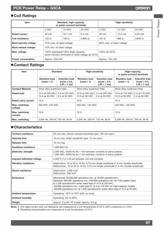
97
PCB Power Relay – G5CA
Characteristics
Contact resistance 30 mΩ max. (Quick-connect terminals type: 100 mΩ max.)
Operate time 10 ms max. (High-sensitivity type: 15 ms max.)
Release time 10 ms max.
Insulation resistance 1,000 MΩ min.
Dielectric strength 2,500 VAC, 50/60 Hz for 1 min between contacts of same polarity1,000 VAC, 50/60 Hz for 1 min between contacts of same polarity
Impulse withstand voltage 4,500 V (1.2 x 50 µs) between coil and contacts
Vibration resistance Destruction: 10 to 55 to 10 Hz, 0.75-mm single amplitude (1.5-mm double amplitude)Malfunction: 10 to 55 to 10 Hz, 0.75-mm single amplitude (1.5-mm double amplitude)
Shock resistance Destruction: 1,000 m/s2
Malfunction: 200 m/s2
Endurance Mechanical: 20,000,000 operations min. at 18,000 operations/hrElectrical: 300,000 operations min. (100,000 operations min. for Fully sealed Type)at 1,200 operations/hr under rated load of 10 A at 250 VAC;100,000 operations min. under load of 15 A at 110 VAC for high-capacity models100,000 operations min. at 1,200 operations/hr under rated load of 10 A at 30 VDC
Ambient temperature Operating: -25˚C to 70˚C (with no icing)
Ambient humidity Operating: 5% to 85%
Weight Approx. 8 g (for TP model: Approx. 9.6 g)
Note: 1. The rated current and coil resistance are measured at a coil temperature of 23°C with a tolerance of ±10%.2. Operating characteristics are measured at a coil temperature of 23°C.
Coil Ratings
Item Standard, high-capacity, High-sensitivityor quick-connect terminals
5 VDC 12 VDC 24 VDC 5 VDC 12 VDC 24 VDC
Rated current 40 mA 16.7 mA 8.3 mA 30 mA 12.5 mA 6.25 mA
Coil resistance 125 Ω 720 Ω 2,880 Ω 167 Ω 960 Ω 3,840 Ω
Must operate voltage 75% max. of rated voltage 80% max. of rated voltage
Must release voltage 10% min. of rated voltage
Max. voltage 150% (standard)/130% (high-capacity, 150% (at 23°C)quick-connect terminals) of rated voltage (at 23°C)
Power consumption Approx. 200 mW Approx. 150 mW
Contact Ratings
Item Standard High-sensitivity High-capacity,or quick-connect terminals
Resistive load Inductive load Resistive load Inductive load Resistive load Inductive load(cosø = 1) (cosø = 0.4, (cosø = 1) (cosø = 0.4, (cosø = 1) (cosø = 0.4,
L/R = 7 ms) L/R = 7 ms) L/R = 7 ms)
Contact Material Silver Alloy (cadmium free) Silver Alloy (cadmium free) Silver Alloy (cadmium free)
Rated load 10 A at 250 VAC; 3 A at 250 VAC; 10 A at 250 VAC; 3 A at 250 VAC; 15 A at 110 VAC; 5 A at 110 VAC;10 A at 30 VDC 3 A at 30 VDC 10 A at 30 VDC 3 A at 30 VDC 10 A at 30 VDC 3 A at 30 VDC
Rated carry current 10 A 10 A 15 A
Max. switching 250 VAC, 125 VDC 250 VAC, 125 VDC 250 VAC, 125 VDCvoltage
Max. switching 10 A 10 A 15 Acurrent
Max. switching 2,500 VA, 300 W 750 VA, 90 W 2,500 VA, 300 W 750 VA, 90 W 2,500 VA, 300 W 750 VA, 90 W
Pow
er R
elay
s
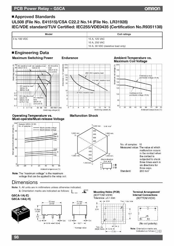
98
PCB Power Relay – G5CA
Engineering Data
Approved StandardsUL508 (File No. E41515)/CSA C22.2 No.14 (File No. LR31928)IEC/VDE standard/TUV Certified: IEC255/VDE0435 (Certification No.R9351138)
Model Coil ratings
3 to 100 VDC 15 A, 125 VAC10 A, 250 VAC10 A, 30 VDC (resistive load only)
DimensionsNote: 1. All units are in millimeters unless otherwise indicated.
2. Orientation marks are indicated as follows:
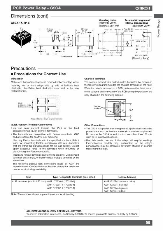
99
PCB Power Relay – G5CA
InstallationMake sure that sufficient space is provided between relays wheninstalling two or more relays side by side to facilitate heatdissipation. Insufficient heat dissipation may result in the relaymalfunctioning.
Quick-connect Terminal Connections• Do not pass current through the PCB of the load
contactterminals (quick-connect terminals).• The terminals are compatible with Faston receptacle #187
and are suitable for positive-lock mounting.Use only Faston terminals with the specified numbers. Selectleads for connecting Faston receptacles with wire diametersthat are within the allowable range for the load current. Do notapply excessive force to the terminals when mounting ordismounting the Faston receptacle.Insert and remove terminals carefully one at a time. Do not insertterminals on an angle, or insert/remove multiple terminals at thesame time.The following positive-lock connectors made by AMP arerecommended. Contact the manufacturer directly for details onconnectors including availability.
Charged TerminalsThe section marked with dotted circles (indicated by arrows) inthe following diagram includes the charged terminals of the relay.When the relay is mounted on a PCB, make sure that there are nometal patterns on the section of the PCB facing the portion of therelay shaded in the following diagram.
Other Precautions• The G5CA is a power relay designed for applications switching
power loads such as heaters in electric household appliances.Do not use the G5CA to switch micro loads less than 100 mA,such as in signal applications.
• Use fully sealed models if the relays will require washing.Fluxprotection models may malfunction or the relay'sperformance may be otherwise adversely affected if cleaningfluid enters the relay.
Precautions
ALL DIMENSIONS SHOWN ARE IN MILLIMETERS.To convert millimeters into inches, multiply by 0.03937. To convert grams into ounces, multiply by 0.03527.
Pow
er R
elay
s
Precautions for Correct Use
Type Type Receptacle terminals (See note.) Positive housing
#187 terminals (width: 4.75 mm) AMP 170330-1 (170324-1) AMP 172074-1 (natural color)AMP 170331-1 (170325-1) AMP 172074-4 (yellow)AMP 170332-1 (170326-1) AMP 172074-5 (green)
AMP 172074-6 (blue)Note: The numbers shown in parentheses are for air-feeding
Dimensions (cont)
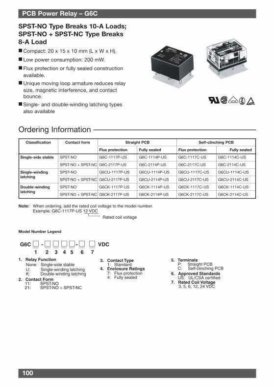
100
Model Number Legend
SPST-NO Type Breaks 10-A Loads;SPST-NO + SPST-NC Type Breaks 8-A Load Compact: 20 x 15 x 10 mm (L x W x H).
Low power consumption: 200 mW.
Flux protection or fully sealed constructionavailable.
Unique moving loop armature reduces relaysize, magnetic interference, and contactbounce.
Single- and double-winding latching typesalso available
VDE
Rated coil voltage
Note: When ordering, add the rated coil voltage to the model number.Example: G6C-1117P-US 12 VDC
G6C - - VDC1 2 3 4 5 6 7
1. Relay Function None: Single-side stable U: Single-winding latching K: Double-winding latching
2. Contact Form 11: SPST-NO 21: SPST-NO + SPST-NC
3. Contact Type 1: Standard
4. Enclosure Ratings 7: Flux protection 4: Fully sealed
5. Terminals P: Straight PCB C: Self-clinching PCB
6. Approved Standards US: UL/CSA certified
7. Rated Coil Voltage 3, 5, 6, 12, 24 VDC
Ordering Information
Classification Contact form Straight PCB Self-clinching PCB
Flux protection Fully sealed Flux protection Fully sealed
Single-side stable SPST-NO G6C-1117P-US G6C-1114P-US G6C-1117C-US G6C-1114C-US
SPST-NO + SPST-NC G6C-2117P-US G6C-2114P-US G6C-2117C-US G6C-2114C-US
SPST-NO G6CU-1117P-US G6CU-1114P-US G6CU-1117C-US G6CU-1114C-US
SPST-NO + SPST-NC G6CU-2117P-US G6CU-2114P-US G6CU-2117C-US G6CU-2114C-US
SPST-NO G6CK-1117P-US G6CK-1114P-US G6CK-1117C-US G6CK-1114C-US
SPST-NO + SPST-NC G6CK-2117P-US G6CK-2114P-US G6CK-2117C-US G6CK-2114C-US
Single-windinglatching
Double-winding latching
PCB Power Relay – G6C
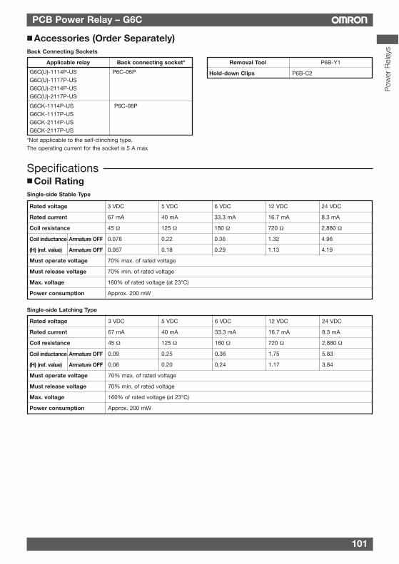
101
PCB Power Relay – G6C
Specifications Coil RatingSingle-side Stable Type
Rated voltage 3 VDC 5 VDC 6 VDC 12 VDC 24 VDC
Rated current 67 mA 40 mA 33.3 mA 16.7 mA 8.3 mA
Coil resistance 45 Ω 125 Ω 180 Ω 720 Ω 2,880 Ω
0.078 0.22 0.36 1.32 4.96
0.067 0.18 0.29 1.13 4.19
Must operate voltage 70% max. of rated voltage
Must release voltage 70% min. of rated voltage
Max. voltage 160% of rated voltage (at 23°C)
Power consumption Approx. 200 mW
Coil inductance Armature OFF
(H) (ref. value) Armature OFF
Single-side Latching Type
Rated voltage 3 VDC 5 VDC 6 VDC 12 VDC 24 VDC
Rated current 67 mA 40 mA 33.3 mA 16.7 mA 8.3 mA
Coil resistance 45 Ω 125 Ω 180 Ω 720 Ω 2,880 Ω
0.09 0.25 0.36 1.75 5.83
0.06 0.20 0.24 1.17 3.84
Must operate voltage 70% max. of rated voltage
Must release voltage 70% min. of rated voltage
Max. voltage 160% of rated voltage (at 23°C)
Power consumption Approx. 200 mW
Coil inductance Armature OFF
(H) (ref. value) Armature OFF
Accessories (Order Separately)Back Connecting Sockets
Applicable relay Back connecting socket*
G6C(U)-1114P-US P6C-06PG6C(U)-1117P-USG6C(U)-2114P-USG6C(U)-2117P-US
G6CK-1114P-US P6C-08PG6CK-1117P-USG6CK-2114P-USG6CK-2117P-US
*Not applicable to the self-clinching type.The operating current for the socket is 5 A max
Removal Tool P6B-Y1
Hold-down Clips P6B-C2
Pow
er R
elay
s
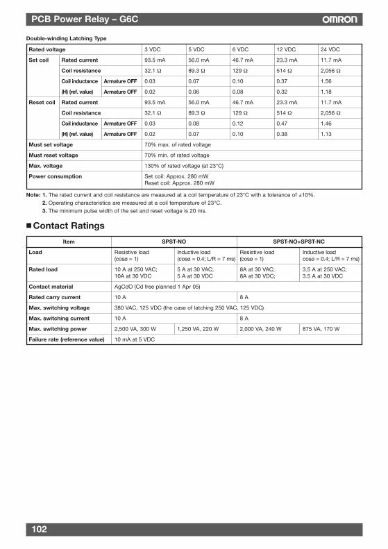
102
PCB Power Relay – G6C
Double-winding Latching Type
Rated voltage 3 VDC 5 VDC 6 VDC 12 VDC 24 VDC
Set coil Rated current 93.5 mA 56.0 mA 46.7 mA 23.3 mA 11.7 mA
Coil resistance 32.1 Ω 89.3 Ω 129 Ω 514 Ω 2,056 Ω
Coil inductance Armature OFF 0.03 0.07 0.10 0.37 1.56
(H) (ref. value) Armature OFF 0.02 0.06 0.08 0.32 1.18
Reset coil Rated current 93.5 mA 56.0 mA 46.7 mA 23.3 mA 11.7 mA
Coil resistance 32.1 Ω 89.3 Ω 129 Ω 514 Ω 2,056 Ω
Coil inductance Armature OFF 0.03 0.08 0.12 0.47 1.46
(H) (ref. value) Armature OFF 0.02 0.07 0.10 0.38 1.13
Must set voltage 70% max. of rated voltage
Must reset voltage 70% min. of rated voltage
Max. voltage 130% of rated voltage (at 23°C)
Power consumption Set coil: Approx. 280 mWReset coil: Approx. 280 mW
Note: 1. The rated current and coil resistance are measured at a coil temperature of 23°C with a tolerance of ±10%.2. Operating characteristics are measured at a coil temperature of 23°C.3. The minimum pulse width of the set and reset voltage is 20 ms.
Contact Ratings
Item SPST-NO SPST-NO+SPST-NC
Load Resistive load Inductive load Resistive load Inductive load(cosø = 1) (cosø = 0.4; L/R = 7 ms) (cosø = 1) cosø = 0.4; L/R = 7 ms)
Rated load 10 A at 250 VAC; 5 A at 30 VAC; 8A at 30 VAC; 3.5 A at 250 VAC;10A at 30 VDC 5 A at 30 VDC 8A at 30 VDC; 3.5 A at 30 VDC
Contact material AgCdO (Cd free planned 1 Apr 05)
Rated carry current 10 A 8 A
Max. switching voltage 380 VAC, 125 VDC (the case of latching 250 VAC, 125 VDC)
Max. switching current 10 A 8 A
Max. switching power 2,500 VA, 300 W 1,250 VA, 220 W 2,000 VA, 240 W 875 VA, 170 W
Failure rate (reference value) 10 mA at 5 VDC
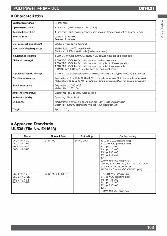
103
PCB Power Relay – G6C
Characteristics
Contact resistance 30 mΩ max.
Operate (set) time 10 ms max. (mean value: approx. 5 ms)
Release (reset) time 10 ms max. (mean value: approx. 2 ms; latching types: mean value: approx. 5 ms)
Bounce Time Operate: 5 ms max.Release: 5 ms max.
Min. set/reset signal width Latching type: 20 ms (at 23˚C)
Max. switching frequency Mechanical: 18,000 operations/hrElectrical: 1,800 operations/hr (under rated load)
Insulation resistance 1,000 MΩ min. (at 500 VDC, at 250 VDC between set coil and reset coil)
Dielectric strength 2,000 VAC, 50/60 Hz for 1 min between coil and contacts2,000 VAC, 50/60 Hz for 1 min between contacts of different polarity1,000 VAC, 50/60 Hz for 1 min between contacts of same polarity250 VAC, 50/60 Hz for 1 min between set and reset coils
Impulse withstand voltage 6.000 V (1.2 x 50 µs) between coil and contacts (latching types: 4,500 V, 1.2 50 µs)
Vibration resistance Destruction: 10 to 55 to 10 Hz, 0.75-mm single amplitude (1.5-mm double amplitude)Malfunction: 10 to 55 to 10 Hz, 0.75-mm single amplitude (1.5-mm double amplitude)
Shock resistance Destruction: 1,000 m/s2
Malfunction: 100 m/s2
Ambient temperature Operating: -25˚C to 70˚C (with no icing)
Ambient humidity Operating: 5% to 85%
Endurance Mechanical: 50,000,000 operations min. (at 18,000 operations/hr)Electrical: 100,000 operations min. (at 1,800 operations/hr)
Weight Approx. 5.6 g
Approved StandardsUL508 (File No. E41643)
Model Contact form Coil rating Contact rating
G6C-1114P-US SPST-NO 3 to 60 VDC 10 A, 250 VAC (general use)G6C-1114C-US 10 A, 30 VDC (resistive load)G6C-1117P-US 1/6 hp, 125 VACG6C-1117C-US 1/4 hp, 125 VAC
1/4 hp, 250 VAC1/3 hp, 250 VACTV-5600 W, 120 VAC (tungsten)530 VA, 20 to 265 VAC, 2 A max. (pilot duty)43.2 VA, 30 VDC (pilot duty)12LRA, 2.2FLA, 30 VDC (30,000 cycle)
G6C-2114P-US SPST-NO + SPST-NC 8 A, 250 VAC (general use)G6C-2114C–US 8 A, 30 VDC (resistive load)G6C-2117P-US 1/6 hp, 125 VACG6C-2117C-US 1/4 hp, 125 VAC
1/4 hp, 250 VACTV-5600 W, 120 VAC (tungsten)
Pow
er R
elay
s
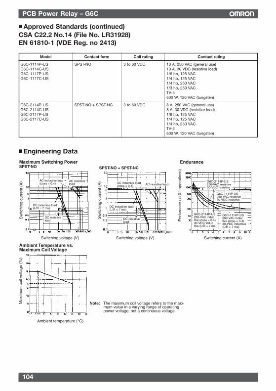
104
PCB Power Relay – G6C
Model Contact form Coil rating Contact rating
G6C-1114P-US SPST-NO 3 to 60 VDC 10 A, 250 VAC (general use)G6C-1114C-US 10 A, 30 VDC (resistive load)G6C-1117P-US 1/6 hp, 125 VACG6C-1117C-US 1/4 hp, 125 VAC
1/4 hp, 250 VAC1/3 hp, 250 VACTV-5600 W, 120 VAC (tungsten)
G6C-2114P-US SPST-NO + SPST-NC 3 to 60 VDC 8 A, 250 VAC (general use)G6C-2114C-US 8 A, 30 VDC (resistive load)G6C-2117P-US 1/6 hp, 125 VACG6C-2117C-US 1/4 hp, 125 VAC
1/4 hp, 250 VACTV-5600 W, 120 VAC (tungsten)
Maximum Switching PowerSPST-NO
Switching voltage (V)
SPST-NO + SPST-NCEndurance
End
uran
ce (
x10
ope
ratio
ns)
3
Sw
itchi
ng c
urre
nt (
A)
Switching current (A)Switching voltage (V)
Sw
itchi
ng c
urre
nt (
A)AC resistive
loadAC inductive load (cosφ = 0.4)
DC resistive load
DC inductive load(L/R = 7 ms)
AC resistive loadAC inductive load (cosφ = 0.4)
DC inductive load(L/R = 7 ms)
G6C-2114P-US250-VAC resistive30-VDC resistive
G6C-1114P-US250-VAC resistive30-VDC resistive
G6C-2114P-US250-VAC inductive (cosφ = 0.4)30-VDC inductive (L/R = 7 ms)
G6C-1114P-US250-VAC inductive (cosφ = 0.4)30-VDC inductive (L/R = 7 ms)
DC resistive load
Ambient Temperature vs. Maximum Coil Voltage
Max
imum
coi
l vol
tage
(%
)
Ambient temperature (°C)
Note: The maximum coil voltage refers to the maxi-mum value in a varying range of operating power voltage, not a continuous voltage.
Engineering Data
Approved Standards (continued)CSA C22.2 No.14 (File No. LR31928)EN 61810-1 (VDE Reg. no 2413)
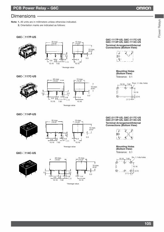
105
PCB Power Relay – G6C
DimensionsNote: 1. All units are in millimeters unless otherwise indicated.
2. Orientation marks are indicated as follows:
Terminal Arrangement/Internal Connections (Bottom View)
Mounting Holes (Bottom View)
G6C-117P-US
G6C-117C-US
G6C-1117P-US, G6C-1117C-USG6C-1114P-US, G6C-1114C-US
Tolerance: ±0.1
*Average value
*Average value
20 max. (19.9)*
3.5
0.80.80.6
10.16 7.621.11
15 max. (14.9)*
10 max. (9.9)*
0.3
10.16
0.4
20 max. (19.9)*
15 max. (14.9)*
0.80.80.6 0.4
10.16 7.621.11
10.16
0.3
10 max. (9.9)*
3.53.2 10.16
(2.4)
10.16 7.62
(1.1)
Four, 1.1-dia. holes
8
1 3 4
+
-
G6C-2117P-US, G6C-2117C-USG6C-2114P-US, G6C-2114C-US
G6C-114P-US
G6C-114C-US
*Average value
*Average value
20 max. (19.9)*
15 max. (14.9)*
10 max. (9.9)*
0.3
3.5
0.8 0.80.6 0.4
10.161.11
7.62 10.16
20 max. (19.9)*
15 max. (14.9)*
10 max. (9.9)*
0.33.5
0.8 0.80.6 0.4
10.161.11
7.62 10.16
3.2
Terminal Arrangement/Internal Connections (Bottom View)
Mounting Holes (Bottom View)Tolerance: ±0.1
8
1 3 4
+
-
6 5
10.16 7.62
10.16
(1.1)(2.4)
Six, 1.1-dia holesP
ower
Rel
ays
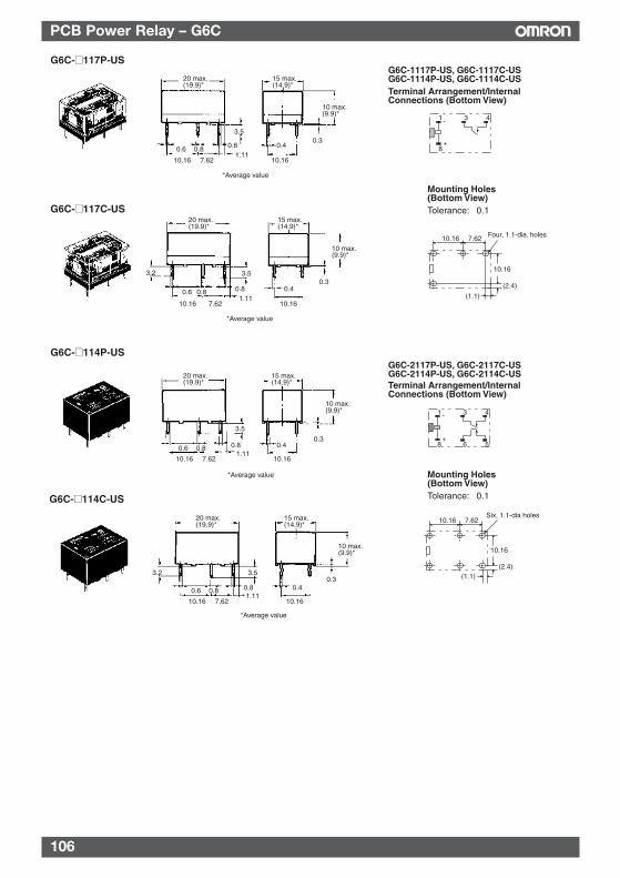
106
PCB Power Relay – G6C
Terminal Arrangement/Internal Connections (Bottom View)
Mounting Holes (Bottom View)
G6C-117P-US
G6C-117C-US
G6C-1117P-US, G6C-1117C-USG6C-1114P-US, G6C-1114C-US
Tolerance: ±0.1
*Average value
*Average value
20 max. (19.9)*
3.5
0.80.80.6
10.16 7.621.11
15 max. (14.9)*
10 max. (9.9)*
0.3
10.16
0.4
20 max. (19.9)*
15 max. (14.9)*
0.80.80.6 0.4
10.16 7.621.11
10.16
0.3
10 max. (9.9)*
3.53.2 10.16
(2.4)
10.16 7.62
(1.1)
Four, 1.1-dia. holes
8
1 3 4
+
-
G6C-2117P-US, G6C-2117C-USG6C-2114P-US, G6C-2114C-US
G6C-114P-US
G6C-114C-US
*Average value
*Average value
20 max. (19.9)*
15 max. (14.9)*
10 max. (9.9)*
0.3
3.5
0.8 0.80.6 0.4
10.161.11
7.62 10.16
20 max. (19.9)*
15 max. (14.9)*
10 max. (9.9)*
0.33.5
0.8 0.80.6 0.4
10.161.11
7.62 10.16
3.2
Terminal Arrangement/Internal Connections (Bottom View)
Mounting Holes (Bottom View)Tolerance: ±0.1
8
1 3 4
+
-
6 5
10.16 7.62
10.16
(1.1)(2.4)
Six, 1.1-dia holes
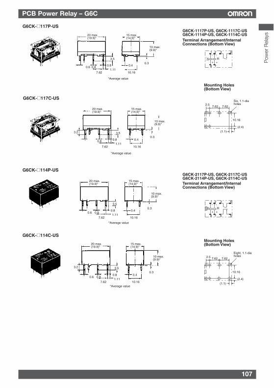
107
PCB Power Relay – G6C
G6CK-117P-USG6CK-1117P-US, G6CK-1117C-USG6CK-1114P-US, G6CK-1114C-US
*Average value
20 max. (19.9)*
15 max. (14.9)*
10 max. (9.9)*
0.33.5
0.8 0.80.6 0.41.11
7.62 10.16
Terminal Arrangement/Internal Connections (Bottom View)
Mounting Holes (Bottom View)
10.16
(2.4)
7.62 7.622.5
(1.1)
Six, 1.1-dia holes
G6CK-117C-US
*Average value
20 max. (19.9)*
15 max. (14.9)*
10 max. (9.9)*
0.33.5
0.8 0.8 0.41.11
7.62 10.16
1 2 3 4
78
S R+
-
+
-
G6CK-2117P-US, G6CK-2117C-USG6CK-2114P-US, G6CK-2114C-US
G6CK-114P-US
G6CK-114C-US
*Average value
*Average value
Terminal Arrangement/Internal Connections (Bottom View)
Mounting Holes (Bottom View)
20 max. (19.9)*
15 max. (14.9)*
10 max. (9.9)*
0.33.5
0.80.8
0.60.4
1.117.62 10.16
20 max. (19.9)*
15 max. (14.9)*
10 max. (9.9)*
0.33.5
0.80.8
0.60.4
1.117.62 10.16
1 2 3 4
5678
S R+
-
+
-
3.2
3.2
10.16
(2.4)
7.62 7.622.5
(1.1)
Eight, 1.1-dia holes
Pow
er R
elay
s
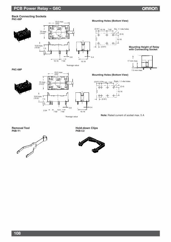
108
PCB Power Relay – G6C
Mounting Holes (Bottom View)
Mounting Height of Relay with Connecting Socket
P6C-08P
Note: Rated current of socket max. 5 A
Back Connecting SocketsP6C-06P
23.2 max. (23)*
15 max. (14.9)* 3.1
10.8 max. (10.6)* 7.5
3.5
0.8 0.4
10.16 7.62 10.16 17 mm max.
7.5 mm max.
7.62
10.16
10.16(2.61)
(2.4)
(2.61)
Six, 1.1-dia holes
7.62
10.16
7.62(2.61)
(2.4)
(2.61)
Eight, 1.1-dia holes2.54
Removal ToolP6B-Y1
Hold-down ClipsP6B-C2
23.2 max. (23)*
15 max. (14.9)* 3.1
10.8 max. (10.6)* 7.5
3.5
2.540.8 0.4
7.62 7.62 10.16
*Average value
*Average value
Mounting Holes (Bottom View)
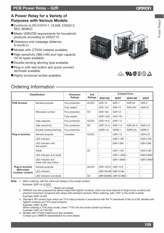
109
PCB Power Relay – G2R
Rated coil voltage
Note: 1. When ordering, add the rated coil voltage to the model number.Example: G2R-1A 12 VDC
2. OMRON has also prepared the above relays with AgSnIn contacts, which are more tolerant of large inrush currents and physical movement compared with relays with standard contacts. When ordering, add "-ASI" to the model number.Example: G2R-1A-ASI
3. Standard, NO contact type relays are TV-3 class products in accordance with the TV standards of the UL/CSA. Models with AgSnIn contacts are TV-5 class products.Example: G2R-1A-ASIWhen ordering a TV-8 class model, insert "-TV8" into the model number as follows:Example: G2R-1A-TV8-ASI
4. Models with CTI250 material are also available.Contact your OMRON representative for more details.
Ordering Information
Classification EnclosureRatings
CoilRatings
Contact Form
SPST-NO SPDT DPST-NO DPDT
PCB terminal General-purpose Flux protection AC/DC G2R-1A G2R-1 G2R-2A G2R-2
Fully sealed G2R-1A4 G2R-14 G2R-2A4 G2R-24
Bifurcated contact Flux protection DC G2R-1AZ G2R-1Z – –
Fully sealed G2R-1AZ4 G2R-1Z4 – –
High-capacity Flux protection AC/DC G2R-1A-E G2R-1-E – –
High-sensitivity Flux protection DC G2R-1A-H G2R-1-H G2R-2A-H G2R-2-H
Double-winding latching Flux protection G2RK-1A G2RK-1 G2RK-2A G2RK-2
Plug-in terminal General-purpose Unsealed AC/DC – G2R-1-S – G2R-2-S
LED indicator – G2R-1-SN – G2R-2-SN
LED indicator with – G2R-1-SNI – G2R-2-SNItest button
Diode DC – G2R-1-SD – G2R-2-SD
LED indicator and diode – G2R-1-SND – G2R-2-SND
LED indicator and – G2R-1-SNDI – G2R-2-SNDIdiode with test button
General-purpose AC/DC G2R-1A3-S G2R-13-S – –
LED indicator G2R-1A3-SN G2R-13-SN – –
LED indicator and diode DC G2R-1A3-SND G2R-13-SND – –
VDE
Plug-in terminal(Bifurcated
crossbar contact)
A Power Relay for a Variety ofPurposes with Various Models Conforms to EN 61810-1, UL508, CSA22.2,
SEV, SEMKO. Meets VDE0700 requirements for household
products according to VDE0110. Clearance and creepage distance:
8 mm/8 m. Models with CTI250 material available. High-sensitivity (360 mW) and high-capacity
(16 A) types available. Double-winding latching type available. Plug-in with test button and quick-connect
terminals available. Highly functional socket available.
Pow
er R
elay
s
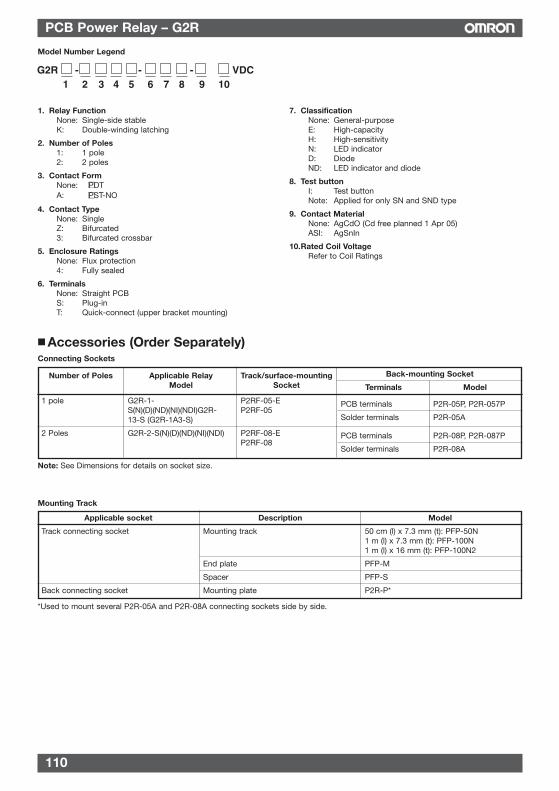
110
PCB Power Relay – G2R
Mounting Track
Model Number Legend
G2R - - - VDC 1 2 3 4 5 6 7 8 9 10
1. Relay FunctionNone: Single-side stableK: Double-winding latching
2. Number of Poles1: 1 pole2: 2 poles
3. Contact FormNone: PDTA: PST-NO
4. Contact TypeNone: SingleZ: Bifurcated3: Bifurcated crossbar
5. Enclosure RatingsNone: Flux protection4: Fully sealed
6. TerminalsNone: Straight PCB S: Plug-inT: Quick-connect (upper bracket mounting)
7. ClassificationNone: General-purposeE: High-capacityH: High-sensitivityN: LED indicatorD: DiodeND: LED indicator and diode
8. Test buttonI: Test buttonNote: Applied for only SN and SND type
9. Contact MaterialNone: AgCdO (Cd free planned 1 Apr 05)ASI: AgSnIn
10.Rated Coil VoltageRefer to Coil Ratings
Applicable socket Description Model
Track connecting socket Mounting track 50 cm (l) x 7.3 mm (t): PFP-50N1 m (l) x 7.3 mm (t): PFP-100N1 m (l) x 16 mm (t): PFP-100N2
End plate PFP-M
Spacer PFP-S
Back connecting socket Mounting plate P2R-P*
*Used to mount several P2R-05A and P2R-08A connecting sockets side by side.
Accessories (Order Separately)Connecting Sockets
Back-mounting Socket
Terminals Model
1 pole G2R-1- P2RF-05-ES(N)(D)(ND)(NI)(NDI)G2R- P2RF-0513-S (G2R-1A3-S)
2 Poles G2R-2-S(N)(D)(ND)(NI)(NDI) P2RF-08-EP2RF-08
Number of Poles Applicable Relay Track/surface-mountingModel Socket
Note: See Dimensions for details on socket size.
PCB terminals P2R-05P, P2R-057P
Solder terminals P2R-05A
PCB terminals P2R-08P, P2R-087P
Solder terminals P2R-08A
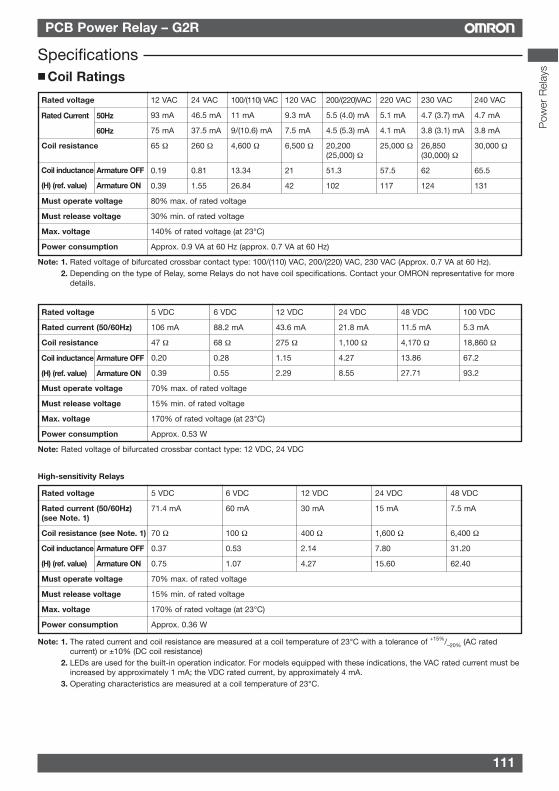
111
PCB Power Relay – G2R
Pow
er R
elay
s
High-sensitivity Relays
Specifications Coil Ratings
Rated voltage 5 VDC 6 VDC 12 VDC 24 VDC 48 VDC 100 VDC
Rated current (50/60Hz) 106 mA 88.2 mA 43.6 mA 21.8 mA 11.5 mA 5.3 mA
Coil resistance 47 Ω 68 Ω 275 Ω 1,100 Ω 4,170 Ω 18,860 Ω
0.20 0.28 1.15 4.27 13.86 67.2
0.39 0.55 2.29 8.55 27.71 93.2
Must operate voltage 70% max. of rated voltage
Must release voltage 15% min. of rated voltage
Max. voltage 170% of rated voltage (at 23°C)
Power consumption Approx. 0.53 W
Note: Rated voltage of bifurcated crossbar contact type: 12 VDC, 24 VDC
Coil inductance Armature OFF
(H) (ref. value) Armature ON
Rated voltage 5 VDC 6 VDC 12 VDC 24 VDC 48 VDC
Rated current (50/60Hz) 71.4 mA 60 mA 30 mA 15 mA 7.5 mA(see Note. 1)
Coil resistance (see Note. 1) 70 Ω 100 Ω 400 Ω 1,600 Ω 6,400 Ω
0.37 0.53 2.14 7.80 31.20
0.75 1.07 4.27 15.60 62.40
Must operate voltage 70% max. of rated voltage
Must release voltage 15% min. of rated voltage
Max. voltage 170% of rated voltage (at 23°C)
Power consumption Approx. 0.36 W
Note: 1. The rated current and coil resistance are measured at a coil temperature of 23°C with a tolerance of +15%/–20% (AC ratedcurrent) or ±10% (DC coil resistance)
2. LEDs are used for the built-in operation indicator. For models equipped with these indications, the VAC rated current must beincreased by approximately 1 mA; the VDC rated current, by approximately 4 mA.
3. Operating characteristics are measured at a coil temperature of 23°C.
Coil inductance Armature OFF
(H) (ref. value) Armature ON
Rated voltage 12 VAC 24 VAC 100/(110) VAC 120 VAC 200/(220)VAC 220 VAC 230 VAC 240 VAC
93 mA 46.5 mA 11 mA 9.3 mA 5.5 (4.0) mA 5.1 mA 4.7 (3.7) mA 4.7 mA
75 mA 37.5 mA 9/(10.6) mA 7.5 mA 4.5 (5.3) mA 4.1 mA 3.8 (3.1) mA 3.8 mA
Coil resistance 65 Ω 260 Ω 4,600 Ω 6,500 Ω 20,200 25,000 Ω 26,850 30,000 Ω(25,000) Ω (30,000) Ω
0.19 0.81 13.34 21 51.3 57.5 62 65.5
0.39 1.55 26.84 42 102 117 124 131
Must operate voltage 80% max. of rated voltage
Must release voltage 30% min. of rated voltage
Max. voltage 140% of rated voltage (at 23°C)
Power consumption Approx. 0.9 VA at 60 Hz (approx. 0.7 VA at 60 Hz)
Note: 1. Rated voltage of bifurcated crossbar contact type: 100/(110) VAC, 200/(220) VAC, 230 VAC (Approx. 0.7 VA at 60 Hz).2. Depending on the type of Relay, some Relays do not have coil specifications. Contact your OMRON representative for more
details.
Coil inductance Armature OFF
(H) (ref. value) Armature ON
Rated Current 50Hz
60Hz
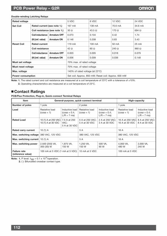
112
PCB Power Relay – G2R
Item General-purpose, quick-connect terminal High-capacity
Number of poles 1 pole 2 poles 1 pole
Load Resistive load Inductive load Resistive load Inductive load Resistive load Inductive load(cosø = 1) (cosø = 0.4; (cosø = 1) (cosø = 0.4; (cosø = 1) (cosø = 0.4;
L/R = 7 ms) L/R = 7 ms) L/R = 7 ms)
Rated Load 10 (1) A at 250 VAC; 7.5 A at 250 5 A at 250 VAC; 2 A at 250 VAC; 16 A at 250 VAC; 8 A at 250 VAC;10 (1) A at 30 VDC VAC; 5 A at 30 VDC 3 A at 30 VDC 16 A at 30 VDC 8 A at 30 VDC
5 A at 30 VDC
Rated carry current 10 (1) A 5 A 16 A
Max. switching voltage 380 VAC, 125 VDC 380 VAC, 125 VDC 380 VAC, 125 VDC
Max. switching current 10 (1) A 5 A 16 A
Max. switching power 2,500 (250) VA, 1,875 VA, 1,250 VA, 500 VA, 4,000 VA, 2,000 VA,300 (30) W 150 W 150 W 90 W 480 W 240 W
Failure rate 100 mA at 5 VDC (1 mA at 5 VDC) 10 mA at 5 VDC 100 mA at 5 VDC(reference value)
Note: 1. P level: λ60 = 0.1 x 10⁻⁶/operation.2. ( ): Bifurcated crossbar contact type.
Contact RatingsPCB/Flux Protection, Plug-in, Quick-connect Terminal Relays
Double-winding Latching Relays
Rated voltage 5 VDC 6 VDC 12 VDC 24 VDC
Rated current (see note 1.) 167 mA 138 mA 70.6 mA 34.6 mA
Coil resistance (see note 1.) 30 Ω 43.5 Ω 170 Ω 694 Ω
0.073 0.104 0.42 1.74
0.146 0.208 0.83 3.43
Rated current 119 mA 100 mA 50 mA 25 mA
Coil resistance 42 Ω 60 Ω 240 Ω 960 Ω
0.003 0.005 0.018 0.079
0.006 0.009 0.036 0.148
Must set voltage 70% max. of rated voltage
Must reset voltage 70% max. of rated voltage
Max. voltage 140% of rated voltage (at 23°C)
Power consumption Set coil: Approx. 850 mW; Reset coil: Approx. 600 mW
Note: 1. The rated current and coil resistance are measured at a coil temperature of 23°C with a tolerance of ±10%.2. Operating characteristics are measured at a coil temperature of 23°C.
Coil inductance Armature OFF
(H) (ref. value) Armature ON
Coil inductance Armature OFF
(H) (ref. value) Armature ON
Set Coil
Reset Coil
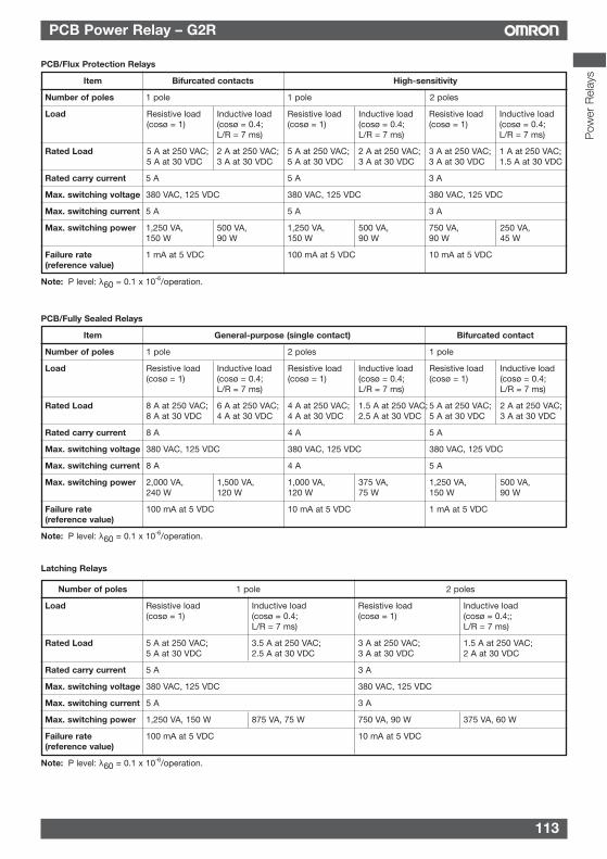
113
PCB Power Relay – G2R
Pow
er R
elay
s
Item Bifurcated contacts High-sensitivity
Number of poles 1 pole 1 pole 2 poles
Load Resistive load Inductive load Resistive load Inductive load Resistive load Inductive load(cosø = 1) (cosø = 0.4; (cosø = 1) (cosø = 0.4; (cosø = 1) (cosø = 0.4;
L/R = 7 ms) L/R = 7 ms) L/R = 7 ms)
Rated Load 5 A at 250 VAC; 2 A at 250 VAC; 5 A at 250 VAC; 2 A at 250 VAC; 3 A at 250 VAC; 1 A at 250 VAC; 5 A at 30 VDC 3 A at 30 VDC 5 A at 30 VDC 3 A at 30 VDC 3 A at 30 VDC 1.5 A at 30 VDC
Rated carry current 5 A 5 A 3 A
Max. switching voltage 380 VAC, 125 VDC 380 VAC, 125 VDC 380 VAC, 125 VDC
Max. switching current 5 A 5 A 3 A
Max. switching power 1,250 VA, 500 VA, 1,250 VA, 500 VA, 750 VA, 250 VA,150 W 90 W 150 W 90 W 90 W 45 W
Failure rate 1 mA at 5 VDC 100 mA at 5 VDC 10 mA at 5 VDC(reference value)
Note: P level: λ60 = 0.1 x 10⁻⁶/operation.
PCB/Flux Protection Relays
Item General-purpose (single contact) Bifurcated contact
Number of poles 1 pole 2 poles 1 pole
Load Resistive load Inductive load Resistive load Inductive load Resistive load Inductive load(cosø = 1) (cosø = 0.4; (cosø = 1) (cosø = 0.4; (cosø = 1) (cosø = 0.4;
L/R = 7 ms) L/R = 7 ms) L/R = 7 ms)
Rated Load 8 A at 250 VAC; 6 A at 250 VAC; 4 A at 250 VAC; 1.5 A at 250 VAC; 5 A at 250 VAC; 2 A at 250 VAC;8 A at 30 VDC 4 A at 30 VDC 4 A at 30 VDC 2.5 A at 30 VDC 5 A at 30 VDC 3 A at 30 VDC
Rated carry current 8 A 4 A 5 A
Max. switching voltage 380 VAC, 125 VDC 380 VAC, 125 VDC 380 VAC, 125 VDC
Max. switching current 8 A 4 A 5 A
Max. switching power 2,000 VA, 1,500 VA, 1,000 VA, 375 VA, 1,250 VA, 500 VA,240 W 120 W 120 W 75 W 150 W 90 W
Failure rate 100 mA at 5 VDC 10 mA at 5 VDC 1 mA at 5 VDC(reference value)
Note: P level: λ60 = 0.1 x 10⁻⁶/operation.
PCB/Fully Sealed Relays
Number of poles 1 pole 2 poles
Load Resistive load Inductive load Resistive load Inductive load(cosø = 1) (cosø = 0.4; (cosø = 1) (cosø = 0.4;;
L/R = 7 ms) L/R = 7 ms)
Rated Load 5 A at 250 VAC; 3.5 A at 250 VAC; 3 A at 250 VAC; 1.5 A at 250 VAC;5 A at 30 VDC 2.5 A at 30 VDC 3 A at 30 VDC 2 A at 30 VDC
Rated carry current 5 A 3 A
Max. switching voltage 380 VAC, 125 VDC 380 VAC, 125 VDC
Max. switching current 5 A 3 A
Max. switching power 1,250 VA, 150 W 875 VA, 75 W 750 VA, 90 W 375 VA, 60 W
Failure rate 100 mA at 5 VDC 10 mA at 5 VDC(reference value)
Note: P level: λ60 = 0.1 x 10⁻⁶/operation.
Latching Relays
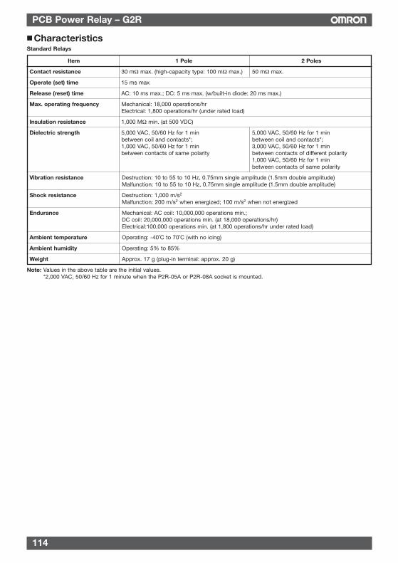
114
PCB Power Relay – G2R
CharacteristicsStandard Relays
Item 1 Pole 2 Poles
Contact resistance 30 mΩ max. (high-capacity type: 100 mΩ max.) 50 mΩ max.
Operate (set) time 15 ms max
Release (reset) time AC: 10 ms max.; DC: 5 ms max. (w/built-in diode: 20 ms max.)
Max. operating frequency Mechanical: 18,000 operations/hrElectrical: 1,800 operations/hr (under rated load)
Insulation resistance 1,000 MΩ min. (at 500 VDC)
Dielectric strength 5,000 VAC, 50/60 Hz for 1 min 5,000 VAC, 50/60 Hz for 1 minbetween coil and contacts*; between coil and contacts*;1,000 VAC, 50/60 Hz for 1 min 3,000 VAC, 50/60 Hz for 1 minbetween contacts of same polarity between contacts of different polarity
1,000 VAC, 50/60 Hz for 1 minbetween contacts of same polarity
Vibration resistance Destruction: 10 to 55 to 10 Hz, 0.75mm single amplitude (1.5mm double amplitude)Malfunction: 10 to 55 to 10 Hz, 0.75mm single amplitude (1.5mm double amplitude)
Shock resistance Destruction: 1,000 m/s2
Malfunction: 200 m/s2 when energized; 100 m/s2 when not energized
Endurance Mechanical: AC coil: 10,000,000 operations min.; DC coil: 20,000,000 operations min. (at 18,000 operations/hr)Electrical:100,000 operations min. (at 1,800 operations/hr under rated load)
Ambient temperature Operating: -40˚C to 70˚C (with no icing)
Ambient humidity Operating: 5% to 85%
Weight Approx. 17 g (plug-in terminal: approx. 20 g)
Note: Values in the above table are the initial values.*2,000 VAC, 50/60 Hz for 1 minute when the P2R-05A or P2R-08A socket is mounted.
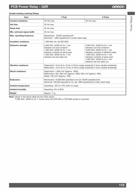
115
PCB Power Relay – G2R
Pow
er R
elay
s
Double-winding Latching Relays
Item 1 Pole 2 Poles
Contact resistance 30 mΩ max. 50 mΩ max.
Set time 20 ms max
Reset time 20 ms max.
Min. set/reset signal width 30 ms max.
Max. operating frequency Mechanical: 18,000 operations/hrElectrical: 1,800 operations/hr (under rated load)
Insulation resistance 1,000 MΩ min. (at 500 VDC)
Dielectric strength 5,000 VAC, 50/60 Hz for 1 min 5,000 VAC, 50/60 Hz for 1 minbetween coil and contacts*; between coil and contacts*;1,000 VAC, 50/60 Hz for 1 min 3,000 VAC, 50/60 Hz for 1 minbetween contacts of same pole; between contacts of different poles1,000 VAC, 50/60 Hz for 1 min 1,000 VAC, 50/60 Hz for 1 minbetween set and reset coil between contacts of same pole
1,000 VAC, 50/60 Hz for 1 minbetween set and reset coil
Vibration resistance Destruction: 10 to 55 to 10 Hz, 0.75mm single amplitude (1.5mm double amplitude)Malfunction: 10 to 55 to 10 Hz, 0.75mm single amplitude (1.5mm double amplitude)
Shock resistance Destruction: 1,000 m/s2 (approx. 100G)Malfunction: Set: 500 m/s2 (approx. 50G); 200 m/s2 (approx. 20G)Reset: 100 m/s2 (approx. 10G)
Endurance Mechanical: 10,000,000 operations min (at 18,000 operations/hr)Electrical: 100,000 operations min. (at 1,800 operations/hr under rated load)
Ambient temperature Operating: -40˚C to 70˚C (with no icing)
Ambient humidity Operating: 5% to 85%
Weight Approx. 17 g
Note: Values in the above table are the initial values.*2,000 VAC, 50/60 Hz for 1 minute when the P2R-05A or P2R-08A socket is mounted.
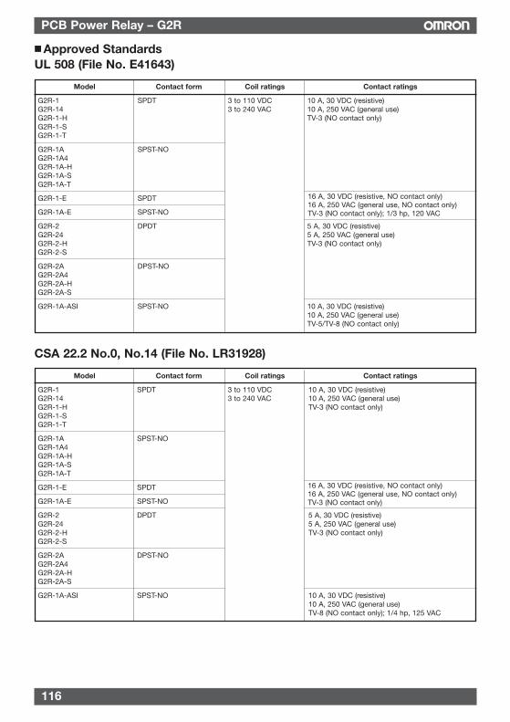
116
PCB Power Relay – G2R
Model Contact form Coil ratings Contact ratings
G2R-1 SPDT 3 to 110 VDC 10 A, 30 VDC (resistive)G2R-14 3 to 240 VAC 10 A, 250 VAC (general use)G2R-1-H TV-3 (NO contact only)G2R-1-SG2R-1-T
G2R-1A SPST-NOG2R-1A4G2R-1A-HG2R-1A-SG2R-1A-T
G2R-1-E SPDT
G2R-1A-E SPST-NO
G2R-2 DPDT 5 A, 30 VDC (resistive)G2R-24 5 A, 250 VAC (general use)G2R-2-H TV-3 (NO contact only)G2R-2-S
G2R-2A DPST-NOG2R-2A4G2R-2A-HG2R-2A-S
G2R-1A-ASI SPST-NO 10 A, 30 VDC (resistive)10 A, 250 VAC (general use)TV-5/TV-8 (NO contact only)
Approved StandardsUL 508 (File No. E41643)
16 A, 30 VDC (resistive, NO contact only)16 A, 250 VAC (general use, NO contact only)TV-3 (NO contact only); 1/3 hp, 120 VAC
Model Contact form Coil ratings Contact ratings
G2R-1 SPDT 3 to 110 VDC 10 A, 30 VDC (resistive)G2R-14 3 to 240 VAC 10 A, 250 VAC (general use)G2R-1-H TV-3 (NO contact only)G2R-1-SG2R-1-T
G2R-1A SPST-NOG2R-1A4G2R-1A-HG2R-1A-SG2R-1A-T
G2R-1-E SPDT
G2R-1A-E SPST-NO
G2R-2 DPDT 5 A, 30 VDC (resistive)G2R-24 5 A, 250 VAC (general use)G2R-2-H TV-3 (NO contact only)G2R-2-S
G2R-2A DPST-NOG2R-2A4G2R-2A-HG2R-2A-S
G2R-1A-ASI SPST-NO 10 A, 30 VDC (resistive)10 A, 250 VAC (general use)TV-8 (NO contact only); 1/4 hp, 125 VAC
CSA 22.2 No.0, No.14 (File No. LR31928)
16 A, 30 VDC (resistive, NO contact only)16 A, 250 VAC (general use, NO contact only)TV-3 (NO contact only)
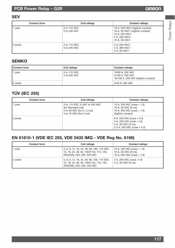
117
PCB Power Relay – G2R
Contact form Coil ratings Contact ratings
1 pole 3 to 110 VDC 16 A, 250 VAC1 (AgSnIn contact)3 to 240 VAC 16 A, 30 VDC1 (AgSnIn contact)
10 A, 250 VAC15 A, 250 VAC310 A, 30 VDC1
2 poles 3 to 110 VDC 5 A, 250 VAC13 to 240 VAC 2 A, 380 VAC1
5 A, 30 VDC1
SEV
Contact form Coil ratings Contact ratings
1 pole 5, 6, 9, 12, 18, 24, 48, 60, 100, 110 VDC 10 A, 250 VAC (cosø = 1.0)12, 18, 24, 48, 50, 100/(110), 110, 120, 10 A, 30 VDC (0 ms)200/(220), 220, 230, 240 VAC 16 A, 250 VAC (cosø = 1.0)
2 poles 5, 6, 9, 12, 18, 24, 48, 60, 100, 110 VDC 5 A, 250 VAC (cosø =1.0)12, 18, 24, 48, 50, 100/(110), 110, 120, 5 A, 30 VDC (0 ms)200/(220), 220, 230, 240 VAC
EN 61810-1 (VDE IEC 255, VDE 0435 IMQ - VDE Reg No. 6166)
Contact form Coil ratings Contact ratings
1 pole 3 to 110 VDC 10/80 A, 250 VAC3 to 240 VAC 3/100 A, 250 VAC
16/128 A, 250 VAC (AgSnIn contact)
2 poles 5/40 A, 250 VAC
SEMKO
Contact form Coil ratings Contact ratings
1 pole 10 A, 250 VAC (cosø = 1.0)10 A, 30 VDC (0 ms)16 A, 250 VAC (cosø = 1.0)(AgSnIn contact)
2 poles 8 A, 250 VAC (cosø = 0.4)5 A, 250 VAC (cosø =1.0)5 A, 30 VDC (0 ms)2.5 A, 250 VAC (cosø = 0.4)
TÜV (IEC 255)
3 to 110 VDC, 6 VAC to 240 VAC(for Standard coil)3 to 48 VDC (for K, U coil)3 to 70 VDC (for H coil)
Pow
er R
elay
s
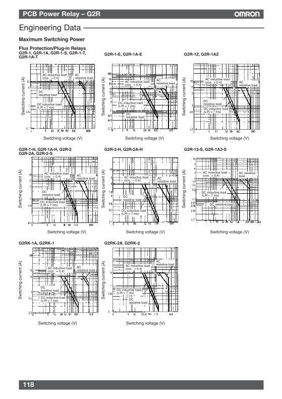
118
PCB Power Relay – G2R
Flux Protection/Plug-in RelaysG2R-1, G2R-1A, G2R-1-S, G2R-1-T, G2R-1A-T
Sw
itchi
ng c
urre
nt (
A)
G2R-1-E, G2R-1A-E G2R-1Z, G2R-1AZ
Switching voltage (V) Switching voltage (V) Switching voltage (V)
G2R-1-H, G2R-1A-H, G2R-2 G2R-2A, G2R-2-S
G2R-2-H, G2R-2A-H
Switching voltage (V) Switching voltage (V)
G2RK-1A, G2RK-1 G2RK-2A, G2RK-2
Switching voltage (V) Switching voltage (V)
Maximum Switching Power
ACresistive load
DCresistive load
AC inductive load (cosφ = 0.4)
DC inductive load (L/R = 7 ms)
ACresistive load
DC inductive load (L/R = 7 ms)
DCresistive load
AC inductive load (cosφ = 0.4)
ACresistive load
AC inductive load (cosφ = 0.4)
DC inductive load (L/R = 7 ms)
DCresistive load
ACresistive load
DCresistive load
DC inductive load (L/R = 7 ms)
DC inductive load (L/R = 7 ms)
DCresistive load
ACresistive load
ACresistive load
ACresistive load
DCresistive load
DCresistive load
DC inductive load (L/R = 7 ms)
DC inductive load (L/R = 7 ms)
AC inductive load (cosφ = 0.4) AC inductive load
(cosφ = 0.4)
AC inductive load (cosφ = 0.4)
AC inductive load (cosφ = 0.4)
Switching voltage (V)
G2R-13-S, G2R-1A3-S
AC inductive load (cosφ = 0.4)
DC inductive load (L/R = 7 ms)
AC resistive load
DC resistive load
Sw
itchi
ng c
urre
nt (
A)
Sw
itchi
ng c
urre
nt (
A)
Sw
itchi
ng c
urre
nt (
A)
Sw
itchi
ng c
urre
nt (
A)
Sw
itchi
ng c
urre
nt (
A)
Sw
itchi
ng c
urre
nt (
A)
Sw
itchi
ng c
urre
nt (
A)
Engineering Data
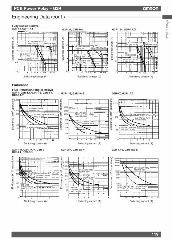
119
PCB Power Relay – G2R
Flux Protection/Plug-in RelaysG2R-1, G2R-1A, G2R-1-S, G2R-1-T, G2R-1A-T
End
uran
ce (
x10
ope
ratio
ns)
3
G2R-1-E, G2R-1A-E G2R-1Z, G2R-1AZ
Switching current (A) Switching current (A) Switching current (A)
G2R-1-H, G2R-1A-H, G2R-2 G2R-2A, G2R-2-S
G2R-2-H, G2R-2A-H
Switching current (A) Switching current (A)
Endurance
250-VAC/30-VDCresistive load
250-VAC inductive load (cosφ = 0.4)
30-VDC inductive load (L/R = 7ms)
250-VAC/30-VDCresistive load
250-VAC (cosφ = 0.4)/30-VDC (L/R = 7 ms) inductive load
30-VDC inductive load (L/R = 7 ms)
250-VAC/30-VDC resistive load
250-VAC inductive load (cosφ = 0.4)
30-VDC inductive load (L/R = 7 ms)30-VDC inductive load (L/R = 7 ms)
250-VAC/30-VDCresistive load
250-VAC/30-VDCresistive load
250-VAC inductive load (cosφ = 0.4) 250-VAC
inductive load (cosφ = 0.4)
5,000
1,000
500
100
50 End
uran
ce (
x10
ope
ratio
ns)
3
End
uran
ce (
x10
ope
ratio
ns)
3
End
uran
ce (
x10
ope
ratio
ns)
3
End
uran
ce (
x10
ope
ratio
ns)
3
5,000
1,000
500
100
50
5,000
1,000
500
100
50
10,000
5,000
3,000
1,000
500
300
100
10,000
5,000
3,000
1,000500
300
100 5030
Switching current (A)
End
uran
ce (
x10
ope
ratio
ns)
3
G2R-13-S, G2R-1A3-S
250-VAC/30-VDC resistive load
250-VAC (cosφ = 0.4)/30-VDC (L/R = 7 ms) inductive load
10,0007,0005,000
3,000
1,000700500
300
1007050
30
Fully Sealed RelaysG2R-14, G2R-1A4
Switching voltage (V) Switching voltage (V) Switching voltage (V)
ACresistive load
AC inductive load (cosφ = 0.4)
DC resistive load
DC inductive load (L/R = 7 ms)
ACresistive load
DC inductive load (L/R = 7 ms)
DCresistive load
ACresistive load
DC inductive load (L/R = 7 ms)
DCresistive load
AC inductive load (cosφ = 0.4)
AC inductive load (cosφ = 0.4)
Sw
itchi
ng c
urre
nt (
A)
Sw
itchi
ng c
urre
nt (
A)
Sw
itchi
ng c
urre
nt (
A)
G2R-24, G2R-2A4 G2R-1Z4, G2R-1AZ4
Engineering Data (cont.)
Pow
er R
elay
s
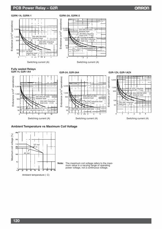
120
PCB Power Relay – G2R
G2RK-1A, G2RK-1 G2RK-2A, G2RK-2
End
uran
ce (
x10
ope
ratio
ns)
3
Switching current (A) Switching current (A)
Fully sealed RelaysG2R-14, G2R-1A4 G2R-24, G2R-2A4 G2R-1Z4, G2R-1AZ4
Switching current (A) Switching current (A) Switching current (A)
30-VDC inductive load (L/R = 7ms)
250-VAC/30-VDCresistive load
250-VAC inductive load (cosφ = 0.4)
250-VAC/30-VDCresistive load30-VDC inductive load (L/R = 7 ms)
250-VAC inductive load (cosφ = 0.4)
250-VAC/30-VDCresistive load
250-VAC/30-VDCresistive load
250-VAC/30-VDCresistive load
250-VAC inductive load (cosφ = 0.4)
250-VAC inductive load (cosφ = 0.4)
250-VAC inductive load (cosφ = 0.4)
30-VDC inductive load (L/R = 7ms)
30-VDC inductive load (L/R = 7 ms)
30-VDC inductive load (L/R = 7 ms)
5,000
1,000
500
100
50
End
uran
ce (
x10
ope
ratio
ns)
3
End
uran
ce (
x10
ope
ratio
ns)
3
End
uran
ce (
x10
ope
ratio
ns)
3
End
uran
ce (
x10
ope
ratio
ns)
3
10,0005,000
1,000500
10050
5,000
1,000
500
100
50
5,000
1,000
500
100
50
5,000
1,000
500
100
50
Ambient temperature (°C)
Max
imum
coi
l vol
tage
(%
)
Ambient Temperature vs Maximum Coil Voltage
DC coil
AC coil
Note: The maximum coil voltage refers to the maxi-mum value in a varying range of operating power voltage, not a continuous voltage.
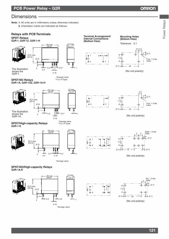
121
PCB Power Relay – G2R
DimensionsNote: 1. All units are in millimeters unless otherwise indicated.
2. Orientation marks are indicated as follows:
Relays with PCB TerminalsSPDT RelaysG2R-1, G2R-1Z, G2R-1-H
Mounting Holes (Bottom View)
Terminal Arrangement/Internal Connections (Bottom View)
Tolerance: ±0.1
The illustration shows the G2R-1.
SPST-NO RelaysG2R-1A, G2R-1AZ, G2R-1A-H
SPDT/High-capacity RelaysG2R-1-E
SPST-NO/High-capacity RelaysG2R-1A-E
The illustration shows the G2R-1A.
29 max. 13 max.
25.5 max.
(0.3)
0.34 0.5 0.5**
0.16
1
29 max.
25.5 max.(25.3)*
(0.3)
4 0.5**0.3
0.16
13 max.
1
29 max.
25.5 max.(25.3)*
(0.3)
4 0.5 0.30.3 0.16
13 max.
1
29 max.
25.5 max.(25.3)*
(0.3)
40.30.3
0.16
13 max.
1
20
7.5
3.5 3.5
(2.1)
(2.7)
Five, 1.3-dia.holes
20
7.5
3.5
(2.1)
(2.7)
Four, 1.3-dia.holes
20
5
7.5
(2.7)
(2.1)(2.1)
Six, 1.3-dia.holes
15
5 5
7.5
(2.7)
(2.1)(2.1)
Eight, 1.3-dia.holes
1
5
2 3
4
1
5
3
4
1
8
2 3 4
567
1
8
3 4
56
(25.3)*
(28.8)* (12.7)*
*Average value
(No coil polarity)
(No coil polarity)
(No coil polarity)
(No coil polarity)
*Average value
*Average value
*Average value
(28.8)*
(28.8)*
(28.8)*
(12.7)*
(12.7)*
(12.7)*
**0.3 (-H Type)
**0.3 (-H Type)
Pow
er R
elay
s
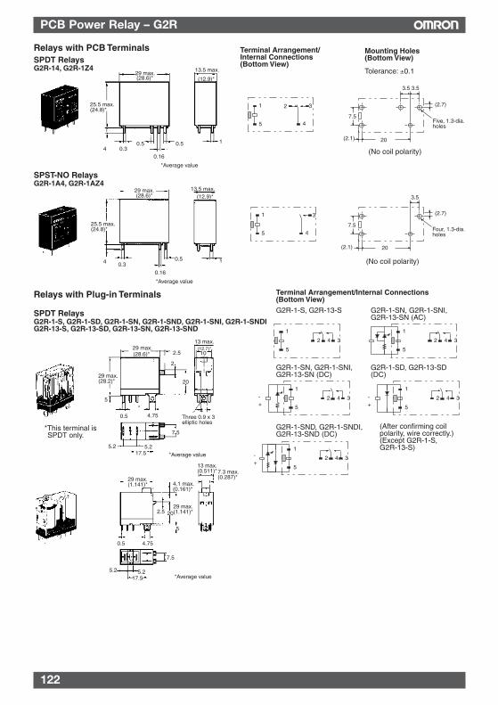
122
PCB Power Relay – G2R
Relays with PCB TerminalsSPDT RelaysG2R-14, G2R-1Z4
Mounting Holes (Bottom View)
Terminal Arrangement/Internal Connections (Bottom View)
Tolerance: ±0.1
SPST-NO RelaysG2R-1A4, G2R-1AZ4
29 max.13.5 max.
25.5 max.(24.8)*
4 0.30.5 0.5
0.16
1
29 max.
25.5 max.(24.8)*
13.5 max.
4 0.30.5
0.16
1
20
7.5
3.5 3.5
(2.1)
(2.7)
Five, 1.3-dia.holes
20
7.5
3.5
(2.1)
(2.7)
Four, 1.3-dia.holes
1
5
2 3
4
1
5
3
4
(28.6)* (12.9)*
*Average value
(No coil polarity)
(28.6)* (12.9)*
*Average value
(No coil polarity)
SPDT RelaysG2R-1-S, G2R-1-SD, G2R-1-SN, G2R-1-SND, G2R-1-SNI, G2R-1-SNDI G2R-13-S, G2R-13-SD, G2R-13-SN, G2R-13-SND
Terminal Arrangement/Internal Connections (Bottom View)
Relays with Plug-in Terminals
G2R-1-S, G2R-13-S G2R-1-SN, G2R-1-SNI, G2R-13-SN (AC)
G2R-1-SN, G2R-1-SNI, G2R-13-SN (DC)
G2R-1-SD, G2R-13-SD (DC)
G2R-1-SND, G2R-1-SNDI, G2R-13-SND (DC)
29 max.2.5
2
29 max.(28.2)*
5
20
0.5 4.75
13 max.
10
4Three 0.9 x 3 elliptic holes
7.5
5.2 5.217.5
1
5
4 32
1
5
4 32
1
5
4 32+-
1
5
4 32+-
1
5
4 32+-
*
*This terminal is SPDT only.
*Average value
(28.6)*(12.7)*
(After confirming coil polarity, wire correctly.) (Except G2R-1-S, G2R-13-S)
29 max.(1.141)* 4.1 max.
(0.161)*
13 max.(0.511)*7.3 max.
(0.287)*
29 max.(1.141)*2.5 20
5
4.750.5
7.5
5.217.5
5.2*Average value
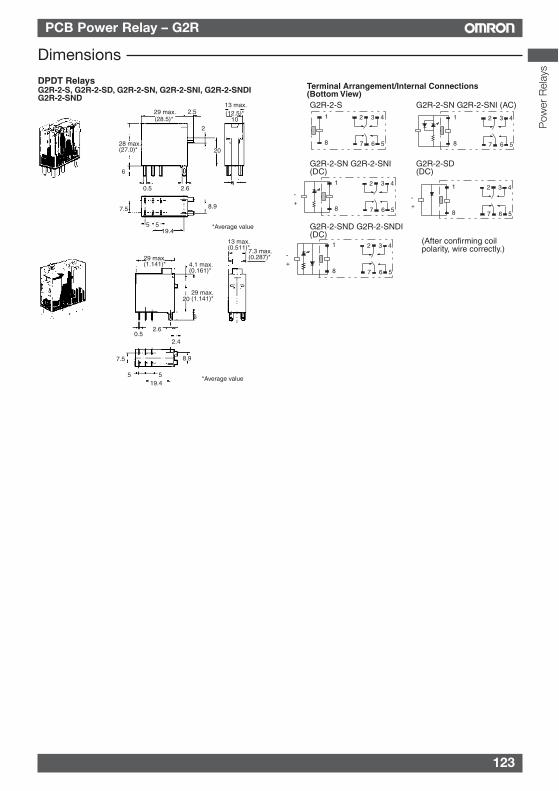
123
PCB Power Relay – G2R
DPDT RelaysG2R-2-S, G2R-2-SD, G2R-2-SN, G2R-2-SNI, G2R-2-SNDIG2R-2-SND
Terminal Arrangement/Internal Connections (Bottom View)G2R-2-S G2R-2-SN G2R-2-SNI (AC)
G2R-2-SN G2R-2-SNI (DC)
G2R-2-SD (DC)
G2R-2-SND G2R-2-SNDI (DC)
29 max. 2.5
28 max.(27.0)*
6
2
20
0.5 2.6
13 max.
10
4
7.5
5 519.4
8.9
1
8 6 57
3 421
8 6 57
3 42
+-
1
8 6 57
3 42
+-
1
8 6 57
3 42
+-
1
8 6 57
3 42
*Average value
(28.5)*(12.5)*
(After confirming coil polarity, wire correctly.)
29 max.(1.141)* 4.1 max.
(0.161)*
13 max.(0.511)*7.3 max.
(0.287)*
29 max.(1.141)*20
6
0.52.6
2.4
7.5
5 519.4
8.9
*Average value
Dimensions
Pow
er R
elay
s
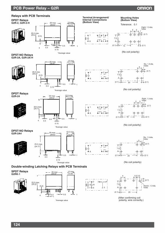
124
PCB Power Relay – G2R
Relays with PCB TerminalsDPDT RelaysG2R-2, G2R-2-H
Mounting Holes (Bottom View)
Terminal Arrangement/Internal Connections (Bottom View)
Tolerance: ±0.1
DPST-NO RelaysG2R-2A, G2R-2A-H
DPDT RelaysG2R-24
DPST-NO RelaysG2R-2A4
Double-winding Latching Relays with PCB Terminals
SPDT RelaysG2RK-1
29 max.
25.5 max.
(0.3)
13 max.
4 0.3
0.50.5
0.15
1
29 max. 13 max.
25.5 max.(25.2)*
(0.3)
0.340.15
0.5 1
29 max. 13.5 max.
25.5 max.(24.7)*
4 0.30.5 0.5
0.15
1
29 max. 13.5 max.
25.5 max.
4 0.3
0.15
0.5 1
29 max. 13 max.
25.5 max.(25.2)*
4
(0.3)
0.31
0.5 1
15
5 5
7.5
(2.7)
(2.1)(2.1)
Eight, 1.3-dia.holes
20
5
7.5
(2.7)
(2.1)(2.1)
Six, 1.3-dia.holes
15
5 5
7.5
(2.7)
(2.1)(2.1)
Eight, 1.3-dia.holes
20
5
7.5
(2.7)
(2.1)(2.1)
Six, 1.3-dia.holes
20
7.5
3.5 3.5
(2.1)
Seven, 1.3-dia.holes
5
(2.7)
1
8
3 42
6 57
1
8
3 4
6 5
1
8
3 42
6 57
1
8
3 4
6 5
1
7
3 4
5
2
6
S R+
-
+
-
(25.2)*
(28.8)* (12.7)*
(12.7)*
*Average value
*Average value
*Average value
*Average value
*Average value
(28.8)*
(24.7)*
(28.8)* (12.8)*
(12.8)*
(12.8)*(28.6)*
(28.6)*
(No coil polarity)
(No coil polarity)
(No coil polarity)
(No coil polarity)
(After confirming coil polarity, wire correctly.)
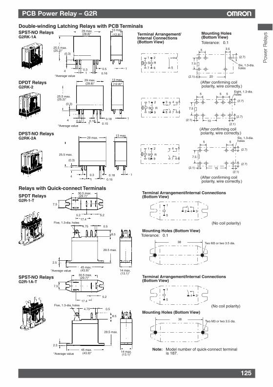
125
PCB Power Relay – G2R
Double-winding Latching Relays with PCB TerminalsSPST-NO RelaysG2RK-1A
Mounting Holes (Bottom View)
Terminal Arrangement/Internal Connections (Bottom View) Tolerance: ±0.1
DPDT RelaysG2RK-2
DPST-NO RelaysG2RK-2A
SPDT RelaysG2R-1-T
Relays with Quick-connect Terminals
SPST-NO RelaysG2R-1A-T
Note: Model number of quick-connect terminal is 187.
29 max. 13 max.
25.5 max.(25.2)*
(0.3)
4 0.3 0.51 0.16
1
29 max. 13 max.
25.5 max.(25.2)*
(0.3)
4 0.3 0.180.18 1
1 0.15
29 max.13 max.
25.5 max.
(0.3)
4 0.3 0.18 1
1 0.15
30.5 max.
7.5
5.2 5.217.4
Five, 1.3-dia. holes4.75 0.5
8.5
29.5 max.
2.5
45 max.14 max.
30.5 max.
7.5
17.45.2
Five, 1.3-dia. holes4.75 0.5
8.5
29.5 max.
2.5
45 max.14 max.
20
7.5
3.5
(2.1)
(2.7)
Six, 1.3-dia.holes
5
10
5 5
7.5
(2.7)
(2.1)(2.1)
Eight, 1.3-dia.holes5
(2.7)
5
7.5
(2.7)
(2.1)(2.1)
Six, 1.3-dia.holes5
15(2.7)
Mounting Holes (Bottom View)Tolerance: ±0.1
38 Two M3 or two 3.5 dia.
Terminal Arrangement/Internal Connections (Bottom View)
Mounting Holes (Bottom View)
Terminal Arrangement/Internal Connections (Bottom View)
38Two M3 or two 3.5 dia.
1
7
4
5
2
6
S R+
-
+
-
1
10
4 53
7 68
2
9S R+
-
+
-
1
10
4 5
7 6
2
9S R+
-
+
-
1
54 32
1
54 3
(After confirming coil polarity, wire correctly.)
(After confirming coil polarity, wire correctly.)
(After confirming coil polarity, wire correctly.)
(No coil polarity)
(No coil polarity)
(28.8)* (12.8)*
(12.8)*(28.8)*
*Average value
*Average value
*Average value
(29.7)*
(13.1)*(43.9)*
(43.9)* (13.1)*
(29.7)*
*Average value
Pow
er R
elay
s
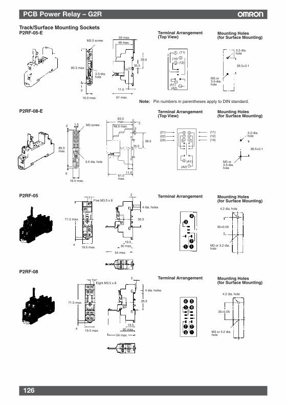
126
PCB Power Relay – G2R
P2RF-05 Mounting Holes(for Surface Mounting)
Terminal Arrangement
P2RF-08
7Five M3.5 x 8
71.5 max.
419.5 max.
2
4 dia. holes
35.5
19.530 max.
54 max.
4.2 dia. hole
30+0.05
M3 or 3.2 dia. hole
7
71.5 max.
419.5 max.
Eight M3.5 x 8
2
4 dia. holes
35.5
19.530 max.
54 max.
4.2 dia. hole
30+0.05
M3 or 3.2 dia. hole
Mounting Holes(for Surface Mounting)
Terminal Arrangement
Track/Surface Mounting SocketsP2RF-05-E Mounting Holes
(for Surface Mounting)Terminal Arrangement(Top View)
3.2-dia. hole
M3 or 3.5-dia. hole
M3.5 screw
85.5 max.
3.5-dia. hole
16.0 max.
59 max.
48 max.
39.5
35.5
11.5
Note: Pin numbers in parentheses apply to DIN standard.61 max.
(11)
(12)(14)
(A1)(A2)
1
2
3
4
5
39.5+0.1
85.5 max.
2 1.5 M3 screw
3.5 dia. hole
16.0 max.
5
63.0max.
48.0 max.2
3
39.5
35.5
11.561.0 max.
P2RF-08-E Terminal Arrangement(Top View)
Mounting Holes(for Surface Mounting)
3.2-dia. hole
M3 or 3.5-dia. hole
39.5+0.1
8
1
6 3
7 2
5 4
(A1)
(A2)
(21)(22)(24)
(11)(12)(14)
5
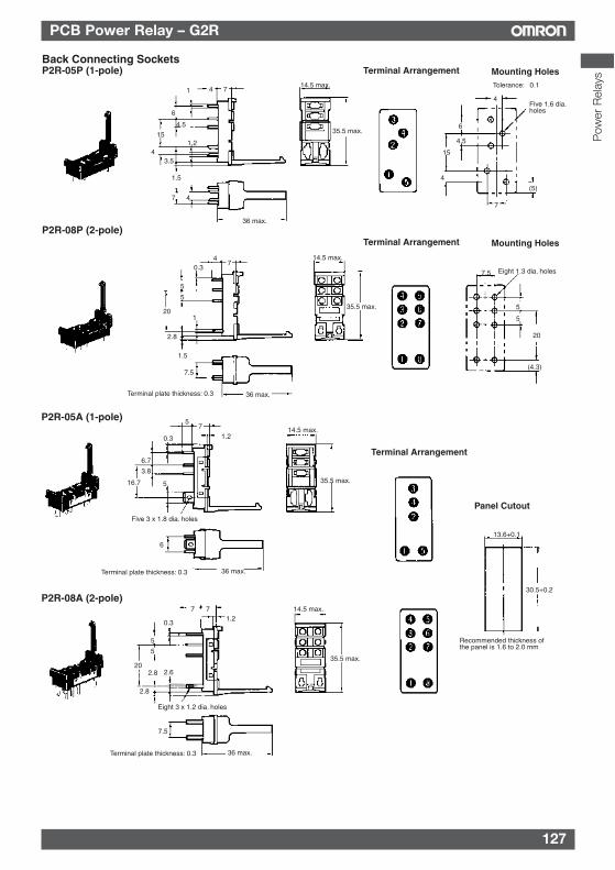
127
PCB Power Relay – G2R
P2R-05A (1-pole)
Panel Cutout
Terminal Arrangement
P2R-08A (2-pole)
75
1.20.3
6.7
3.8
16.7 5
Five 3 x 1.8 dia. holes
6
36 max.Terminal plate thickness: 0.3
14.5 max.
35.5 max.
71.2
0.3
5
36 max.Terminal plate thickness: 0.3
14.5 max.
35.5 max.
7
5
202.8
2.8
2.6
Eight 3 x 1.2 dia. holes
7.5
13.6+0.1
30.5+0.2
Recommended thickness of the panel is 1.6 to 2.0 mm
Back Connecting SocketsP2R-05P (1-pole)
1 4 7
6
4.5
15
43.5
1.2
1.5
7 4
36 max.
14.5 max.
35.5 max.
Tolerance: ±0.1
4
6
4.5
Five 1.6 dia.holes
15
4
7
(5)
Mounting HolesTerminal Arrangement
P2R-08P (2-pole)
47
0.3
5
5
201
2.8
1.5
7.5
36 max.Terminal plate thickness: 0.3
14.5 max.
35.5 max.
7.5 Eight 1.3 dia. holes
5
5
20
(4.3)
Mounting HolesTerminal Arrangement
Pow
er R
elay
s
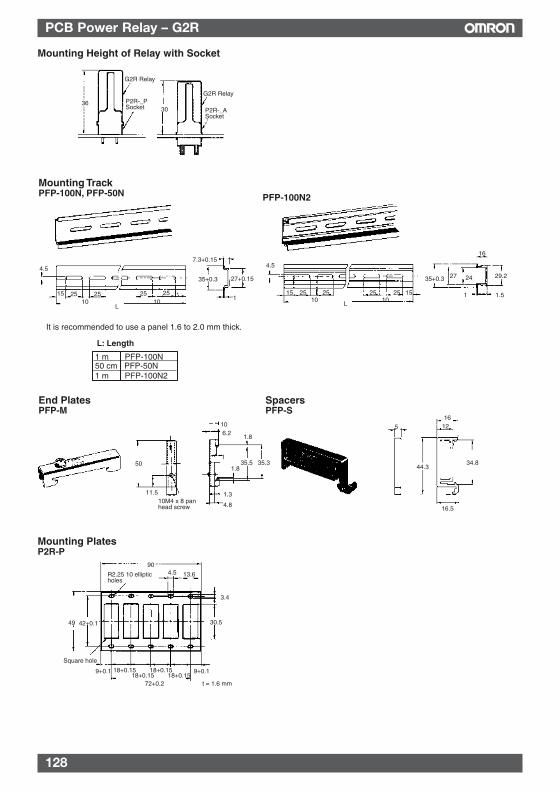
128
PCB Power Relay – G2R
Mounting Height of Relay with Socket
36
G2R Relay
P2R-_P Socket 30
G2R Relay
P2R-_A Socket
Mounting TrackPFP-100N, PFP-50N PFP-100N2
It is recommended to use a panel 1.6 to 2.0 mm thick.
L: Length
1 m PFP-100N50 cm PFP-50N1 m PFP-100N2
End PlatesPFP-M
SpacersPFP-S
4.5
15 25 25 25 25 *10 10
L
7.3+0.15
35+0.3 27+0.15
1
4.5
15 25 25 25 25 1510 10
L
35+0.3 27 24
16
29.2
1 1.5
50
11.510M4 x 8 pan head screw
106.2
1.8
135.5 35.3
1.8
1.3
4.8
5
1612
44.334.8
16.5
Mounting PlatesP2R-P
90
R2.25 10 elliptic holes
4.5 13.6
3.4
30.549 42+0.1
Square hole
9+0.1 18+0.15 18+0.1518+0.15 18+0.15
9+0.1
72+0.2 t = 1.6 mm
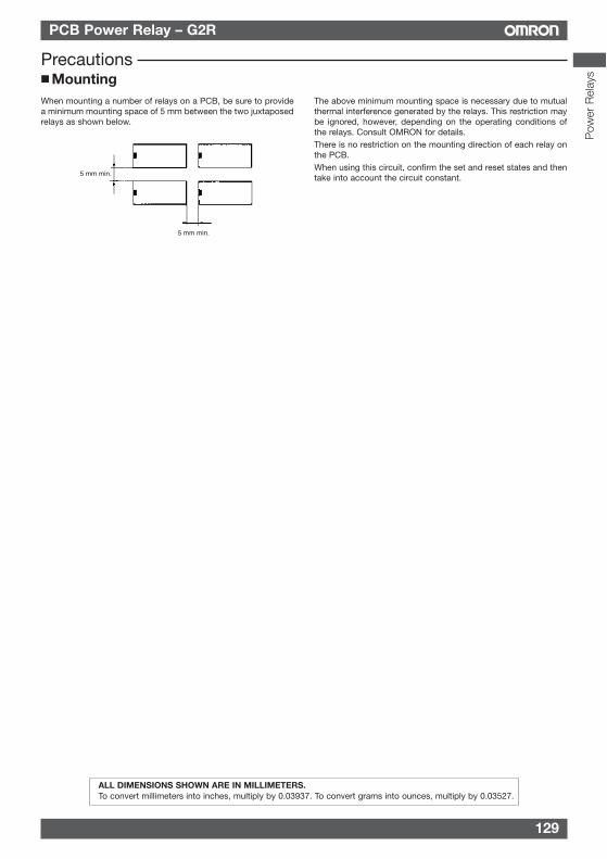
129
PCB Power Relay – G2R
Precautions MountingWhen mounting a number of relays on a PCB, be sure to providea minimum mounting space of 5 mm between the two juxtaposedrelays as shown below.
The above minimum mounting space is necessary due to mutualthermal interference generated by the relays. This restriction maybe ignored, however, depending on the operating conditions ofthe relays. Consult OMRON for details.There is no restriction on the mounting direction of each relay onthe PCB.When using this circuit, confirm the set and reset states and thentake into account the circuit constant.5 mm min.
5 mm min.
ALL DIMENSIONS SHOWN ARE IN MILLIMETERS.To convert millimeters into inches, multiply by 0.03937. To convert grams into ounces, multiply by 0.03527.
Pow
er R
elay
s
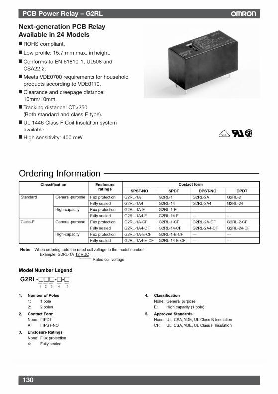
130
PCB Power Relay – G2RL
Next-generation PCB RelayAvailable in 24 Models ROHS compliant.
Low profile: 15.7 mm max. in height.
Conforms to EN 61810-1, UL508 andCSA22.2.
Meets VDE0700 requirements for householdproducts according to VDE0110.
Clearance and creepage distance:10mm/10mm.
Tracking distance: CT>250(Both standard and class F type).
UL 1446 Class F Coil Insulation systemavailable.
High sensitivity: 400 mW
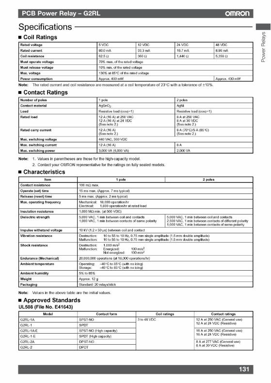
131
PCB Power Relay – G2RL
Pow
er R
elay
s

132
PCB Power Relay – G2RL
EN 61810-1 (VDE 0435) (Licence No. 119650)
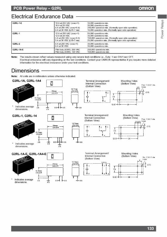
133
PCB Power Relay – G2RL
Pow
er R
elay
s
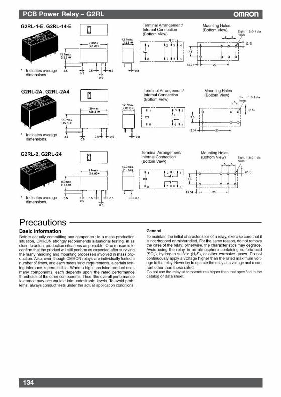
134
PCB Power Relay – G2RL
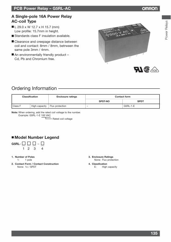
135
PCB Power Relay – G5RL-AC
A Single-pole 16A Power RelayAC-coil Type L 29.0 x W 12.7 x H 15.7 (mm)
Low profile: 15.7mm in height. Standards class F insulation available.
Clearance and creepage distance betweencoil and contact: 8mm / 8mm, betrween thesame pole 3mm / 4mm.
An environmentally friendly product –Cd, Pb and Chromium free.
1. Number of Poles1: 1 pole
2. Contact Form / Contact ConstructionNone: 1c / SPDT
3. Enclosure RatingsNone: Flux protection
4. ClassficationE: High capacity
Model Number Legend
Ordering Information
Classification Enclosure ratings Contact form
SPST-NO SPDT
Class F High-capacity Flux protection – G5RL-1-E
Note: When ordering, add the rated coil voltage to the number.Example: G5RL-1-E 100 VAC
Rated coil voltage
1 2 3
–
4
–G5RL-
VDE
Pow
er R
elay
s
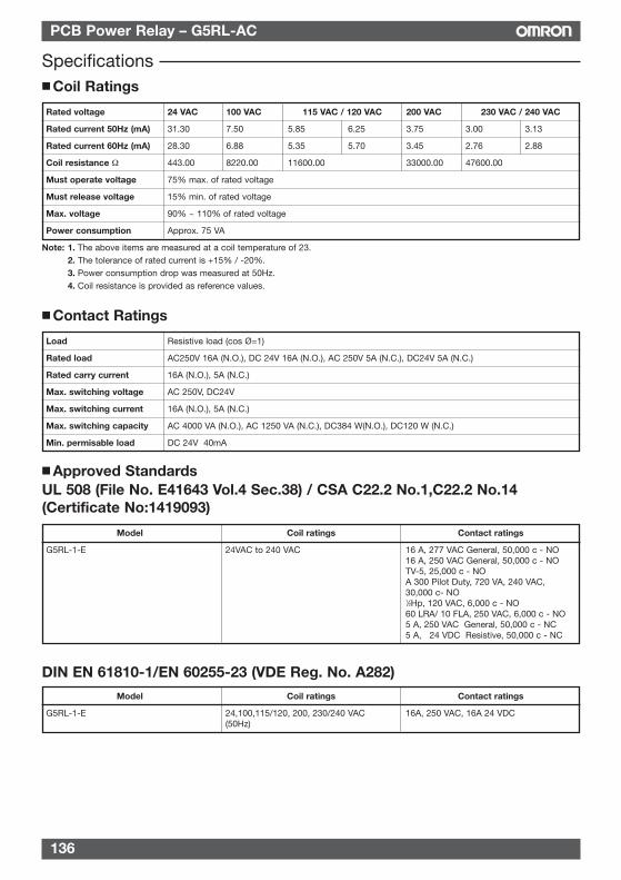
136
PCB Power Relay – G5RL-AC
Coil Ratings
Rated voltage 24 VAC 100 VAC 115 VAC / 120 VAC 200 VAC 230 VAC / 240 VAC
Rated current 50Hz (mA) 31.30 7.50 5.85 6.25 3.75 3.00 3.13
Rated current 60Hz (mA) 28.30 6.88 5.35 5.70 3.45 2.76 2.88
Coil resistance Ω 443.00 8220.00 11600.00 33000.00 47600.00
Must operate voltage 75% max. of rated voltage
Must release voltage 15% min. of rated voltage
Max. voltage 90% ~ 110% of rated voltage
Power consumption Approx. 75 VA
Note: 1. The above items are measured at a coil temperature of 23.2. The tolerance of rated current is +15% / -20%.3. Power consumption drop was measured at 50Hz.4. Coil resistance is provided as reference values.
Contact Ratings
Load Resistive load (cos Ø=1)
Rated load AC250V 16A (N.O.), DC 24V 16A (N.O.), AC 250V 5A (N.C.), DC24V 5A (N.C.)
Rated carry current 16A (N.O.), 5A (N.C.)
Max. switching voltage AC 250V, DC24V
Max. switching current 16A (N.O.), 5A (N.C.)
Max. switching capacity AC 4000 VA (N.O.), AC 1250 VA (N.C.), DC384 W(N.O.), DC120 W (N.C.)
Min. permisable load DC 24V 40mA
Specifications
Approved StandardsUL 508 (File No. E41643 Vol.4 Sec.38) / CSA C22.2 No.1,C22.2 No.14(Certificate No:1419093)
Model Coil ratings Contact ratings
G5RL-1-E 24VAC to 240 VAC 16 A, 277 VAC General, 50,000 c - NO16 A, 250 VAC General, 50,000 c - NOTV-5, 25,000 c - NOA 300 Pilot Duty, 720 VA, 240 VAC, 30,000 c- NO1⁄2Hp, 120 VAC, 6,000 c - NO60 LRA/ 10 FLA, 250 VAC, 6,000 c - NO5 A, 250 VAC General, 50,000 c - NC5 A, 24 VDC Resistive, 50,000 c - NC
DIN EN 61810-1/EN 60255-23 (VDE Reg. No. A282)
Model Coil ratings Contact ratings
G5RL-1-E 24,100,115/120, 200, 230/240 VAC 16A, 250 VAC, 16A 24 VDC(50Hz)
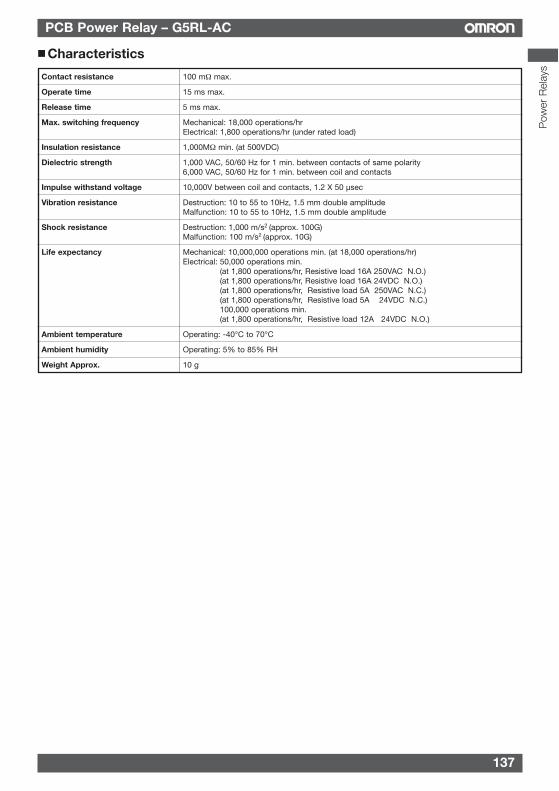
137
PCB Power Relay – G5RL-AC
Pow
er R
elay
s
Characteristics
Contact resistance 100 mΩ max.
Operate time 15 ms max.
Release time 5 ms max.
Max. switching frequency Mechanical: 18,000 operations/hrElectrical: 1,800 operations/hr (under rated load)
Insulation resistance 1,000MΩ min. (at 500VDC)
Dielectric strength 1,000 VAC, 50/60 Hz for 1 min. between contacts of same polarity6,000 VAC, 50/60 Hz for 1 min. between coil and contacts
Impulse withstand voltage 10,000V between coil and contacts, 1.2 X 50 µsec
Vibration resistance Destruction: 10 to 55 to 10Hz, 1.5 mm double amplitudeMalfunction: 10 to 55 to 10Hz, 1.5 mm double amplitude
Shock resistance Destruction: 1,000 m/s2 (approx. 100G)Malfunction: 100 m/s2 (approx. 10G)
Life expectancy Mechanical: 10,000,000 operations min. (at 18,000 operations/hr)Electrical: 50,000 operations min.
(at 1,800 operations/hr, Resistive load 16A 250VAC N.O.)(at 1,800 operations/hr, Resistive load 16A 24VDC N.O.)(at 1,800 operations/hr, Resistive load 5A 250VAC N.C.)(at 1,800 operations/hr, Resistive load 5A 24VDC N.C.)100,000 operations min. (at 1,800 operations/hr, Resistive load 12A 24VDC N.O.)
Ambient temperature Operating: -40°C to 70°C
Ambient humidity Operating: 5% to 85% RH
Weight Approx. 10 g
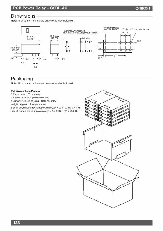
138
PCB Power Relay – G5RL-AC
DimensionsNote: All units are in millimeters unless otherwise indicated.
PackagingNote: All units are in millimeters unless otherwise indicated.
Polystyrene Trays Packing1 Polystyrene: 100 pcs relay1 Sleeve Packing: 5 polystyrene tray1 Carton: 2 sleeve packing –1000 pcs relayWeight: Approx. 12 Kg per cartonSize of polystyrene tray is approximately:340 (L) x 120 (W) x 48 (H)Size of Carton box is approximately: 535 (L) x 355 (W) x 250 (H)
15.7 max.(15.5)?
3.5
0.5
0. .5
0.5
29 max.(28.5)?
12.7 max.(12.5)?
0.8
7.5
(2.3)20
5 5
(2.5)
Eight . 1.3 ± 0.1 dia. holesTerminal ArrangementInternal Connection (Bottom View)
ggMounting Holes(Bottom View)
gg
1
8
2 3 4
7 6 5
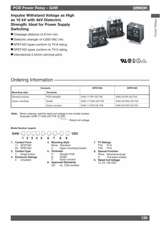
139
PCB Power Relay – G4W
Ordering Information
Impulse Withstand Voltage as Highas 10 kV with 4kV DielectricStrength: Ideal for Power SupplySwitching Creepage distance of 8 mm min.
Dielectric strength of 4,000 VAC min.
SPST-NO types conform to TV-8 rating.
DPST-NO types conform to TV-5 rating.
International 2.54mm terminal pitch.
VDE
Rated coil voltage
Note: When ordering, add the rated coil voltage to the model number.Example: G4W-11123A-US-TV8 12 VDC
G4W - - - - VDC1 2 3 4 5 6 7 8 9
1. Contact Form 11: SPST-NO 22: DPST-NO
2. Contact Type 1: Single button
3. Enclosure Ratings 2: Unsealed
4. Mounting Style None: Standard 3: Upper mounting bracket
5. Terminals P: Straight PCB A: Solder T: Quick connect
6. Approved Standards US: UL, CSA certified
7. TV Ratings TV5: TV-5 TV8: TV-8
8. Special Function None: General-purpose Z: Full-wave rectifier
9. Rated Coil Voltage 12, 24, 100 VDC
Contacts SPST-NO DPST-NO
Mounting style Terminals
General purpose PCB (straight) G4W-1112P-US-TV8 G4W-2212P-US-TV5
Upper mounting Solder G4W-11123A-US-TV8 G4W-22123A-US-TV5
Quick-connect G4W-11123T-US-TV8 G4W-22123T-US-TV5
Model Number Legend
Pow
er R
elay
s
140
PCB Power Relay – G4W
CharacteristicsContact resistance 30 mΩ max.
Operate time 20 ms max. (mean value: approx. 13 ms)
Release time 5 ms max. (mean value: approx. 2.5 ms)
Bounce time Operate: approx. 3 ms
Max. Operating Frequency Mechanical: 18,000 operations/hrElectrical: 1,800 operations/hr (under rated load)
Insulation resistance 100 MΩ max. (at 500 VDC)
Dielectric strength 4,000 VAC, 50/60 Hz for 1 min between coil and contacts2,000 VAC, 50/60 Hz for 1 min between contacts of different polarities (DPST-NO)1,500 VAC, 50/60 Hz for 1 min between contacts of same polarity
Impulse withstand voltage 10,000 V (1.2 x 50 µs) between coil and contacts
Vibration resistance Destruction: 10 to 55 to 10 Hz, 0.75mm single amplitude (1.5mm double amplitude)Malfunction: 10 to 55 to 10 Hz, 0.75mm single amplitude (1.5mm double amplitude)
Shock resistance Destruction: 1,000 m/s2
Malfunction: 150 m/s2
Endurance Mechanical: 5,000,000 operations min. (at 18,000 operations/hr)Electrical: 100,000 operations min. (at 1,800 operations/hr)
Ambient temperature Operating: -25˚C to 55˚C (with no icing)
Ambient humidity Operating: 5% to 85% RH
Weight Approx. 29 g
Rated voltage 12 VDC 24 VDC 100 VDC
Rated current 66.7 mA 33.3 mA 8 mA
Coil resistance 180 Ω 720 Ω 12,500 Ω
0.93 3.7 61.8
1.65 6.4 106
Must operate voltage 80% max. of rated voltage
Must release voltage 10% min. of rated voltage
Max. voltage 130% of rated voltage (at 23°C)
Power consumption Approx. 800 mW
Note: 1. The rated current and coil resistance are measured at a coil temperature of 23°C with a tolerance of ±15%.2. Operating characteristics are measured at a coil temperature of 23°C.
Specifications Coil RatingsSingle-side Stable Type
Coil inductance Armature OFF
(H) (ref. value) Armature ON
Contact RatingsItem SPST-NO DPST-NO
Load Resistive load Inductive load Resistive load Inductive load(cosø = 1) (cosø = 0.4; L/R = 7 ms) (cosø = 1) cosø = 0.4; L/R = 7 ms)
Rated load 15A at 250 VAC; 10A at 250 VAC; 10A at 250 VAC; 7.5A at 250 VAC;15A at 24 VDC 7.5A at 24 VDC 10A at 24 VDC; 5A at 24 VDC
Contact material AgCdO (Cd free planned 1 Apr 05)
Rated carry current 15A 10A
Max. switching voltage 250 VAC, 125 VDC
Max. switching current 15A 10A
Max. switching power 3,750 VA, 375 W 2,500 VA, 255 W 2,500 VA, 240 W 1,850 VA, 120 W
Failure rate (reference value) 100 mA at 5 VDC
141
PCB Power Relay – G4W
Pow
er R
elay
s
Approved StandardsUL508 (File No. E41643)/CSA C22.2 No.14 (File No.LR31928)
SEMKO (File No. 9346122, 9223128)
Contact form Coil ratings Contact ratings
SPST-NO 6-100 VDC 15/120 A, 250 VAC
DPST 6-120 VDC 10/80 A, 250 VAC
Model Contact Form Coil ratings Contact ratings
G4W-1112P-US-TV8 SPST-NO 6 to 120 VDC 15 A, 250 VAC (general use)G4W-11123A-US-TV8 15 A, 24 VDCG4W-11123T-US-TV8 TV-8
1/2 hp, 125 VAC1 hp, 250 VAC3/4 hp, 240 VAC
G4W-2212P-US-TV5 DPST-NO 15 A, 250 VAC (general use)G4W-22123A-US-TV5 10 A, 250 VAC (general use)G4W-22123T-US-TV5 15 A, 24 VDC
TV-51/2 hp, 250 VAC1/3 hp, 125/250 VAC
EN 61810-1 (VDE0435 (File No. 1906, No. 1907)
Contact form Coil ratings Contact ratings
SPST-NO 6, 12, 24, 48, 100 VDC 15 A, 250 VAC (cosø = 1.0)10 A, 250 VAC (cosø = 0.4)15 A, 24 VDC (0 ms)7.5 A, 24 VDC (40 ms)
DPST-NO 10 A, 250 VAC (cosø = 1.0)7.5 A, 250 VAC (cosø = 0.4)10 A, 24 VDC (0 ms)5 A, 24 VDC (40 ms)
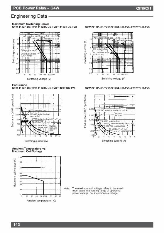
142
PCB Power Relay – G4W
Maximum Switching PowerG4W-1112P-US-TV8/-11123A-US-TV8/-11123T-US-TV8
Switching voltage (V)
G4W-2212P-US-TV5/-22123A-US-TV5/-22123T-US-TV5
EnduranceG4W-1112P-US-TV8/-11123A-US-TV8/-1123T-US-TV8
End
uran
ce (
x10
ope
ratio
ns)
3S
witc
hing
cur
rent
(A
)
Switching voltage (V)
G4W-2212P-US-TV5/-22123A-US-TV5/-22123T-US-TV5
Switching current (A) Switching current (A)
AC inductive load (cosφ = 0.4) AC resistive load
DC resistive load
DC inductive load(L/R = 7 ms)
AC inductive load (cosφ = 0.4) AC resistive load
DC resistive load
DC inductive load(L/R = 7 ms)
Sw
itchi
ng c
urre
nt (
A)
110-VDC resistive load
220-VAC inductive load(cosφ = 0.4)
24-VDC (L/R = 7 ms)
24-VDC resistive load 220-VAC
resistive load
110-VDC inductive load (L/R = 7 ms)
220-VAC inductive load (cosφ = 0.4)
AC loadDC load
110-VDC resistive load110-VDC inductive load (L/R = 7 ms)
24-VDC (L/R = 7 ms)24-VDC resistive load
End
uran
ce (
x10
ope
ratio
ns)
3
220-VAC resistive load
Ambient Temperature vs. Maximum Coil Voltage
Max
imum
coi
l vol
tage
(%
)
Ambient temperature (°C)
20
10
5
2
1
0.5
0.2
0.15 10 20 50 100 200 300
20
10
5
2
1
0.5
0.2
0.15 10 20 50 100 200 300
5,000
2,000
1,000
500
200
1002 8 10 12 154 6 14
5,000
2,000
1,000
500
200
1000 2 4 6 8 10 12 14 16
200
180
140130120
110100
80
0
160
0 70 80 9020 30 40 50 5560
Note: The maximum coil voltage refers to the maxi-mum value in a varying range of operating power voltage, not a continuous voltage.
Engineering Data
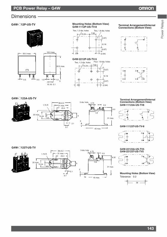
143
PCB Power Relay – G4W
Dimensions
G4W-12P-US-TV Mounting Holes (Bottom View)
G4W-2212P-US-TV-5
G4W-1112P-US-TV-8
30.5 max.19.5 max.
30.5 max.
0.5 0.5 1.5 1.55
10.16±0.1
10.16
15.24 7.62
(5)
(4.67)
(4.67)
(2.64)
Two, 1.8-dia. holesTwo, 1.2-dia. holes
10.16
15.24 7.62
(5)
(4.67)
(4.67)
(2.64)
Four, 1.8-dia. holesTwo, 1.2-dia. holes
Terminal Arrangement/Internal Connections (Bottom View)
5
6 4
1
1
2
3
4
5
6
G4W-123T-US-TV
Mounting Holes (Bottom View)
Terminal Arrangement/Internal Connections (Bottom View)
G4W-123A-US-TV
G4W-11123A-US-TV8
G4W-11123T-US-TV-8
G4W-22123A-US-TV5G4W-22123T-US-TV5
Tolerance: ±0.2
1.75 R38+0.231 max.
23.4
20 max.15.24
3.59
2.1
9.7
3 dia. hole 4.750.5
6.5
31 max.
2
45 max.
3-dia. hole4.75
0.5
31 max.
2
45 max.
8.35
38+0.231 max.
23.41.75 R
20 max.15.24
3.5
9
2.1
9.7
5
6 4
1
5
6
1
2
3
4
5
6
1
2
3
4
38
Pow
er R
elay
s
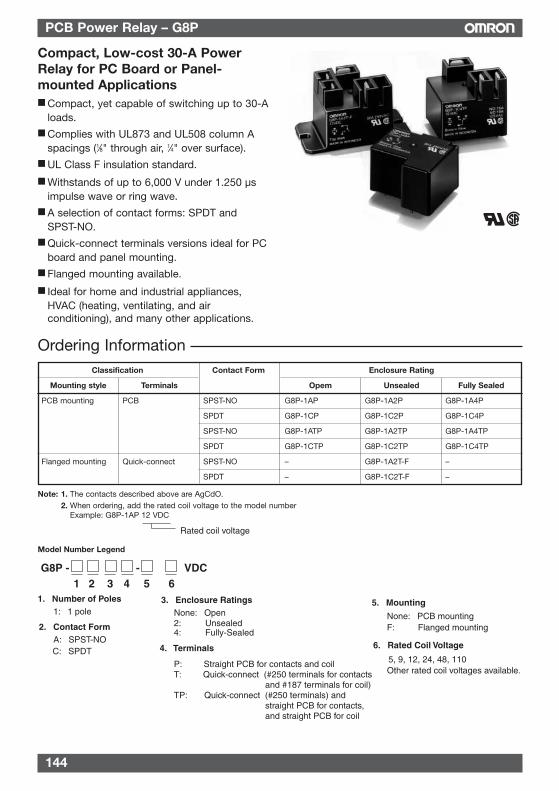
144
PCB Power Relay – G8P
Compact, Low-cost 30-A PowerRelay for PC Board or Panel-mounted Applications Compact, yet capable of switching up to 30-A
loads. Complies with UL873 and UL508 column A
spacings (1⁄8" through air, 1⁄4" over surface). UL Class F insulation standard.
Withstands of up to 6,000 V under 1.250 µsimpulse wave or ring wave.
A selection of contact forms: SPDT andSPST-NO.
Quick-connect terminals versions ideal for PCboard and panel mounting.
Flanged mounting available.
Ideal for home and industrial appliances,HVAC (heating, ventilating, and airconditioning), and many other applications.
G8P - - VDC1 2 3 4 5 6
1. Number of Poles 1: 1 pole
2. Contact Form A: SPST-NO C: SPDT
3. Enclosure RatingsNone: Open2: Unsealed4: Fully-Sealed
4. Terminals
P: Straight PCB for contacts and coilT: Quick-connect (#250 terminals for contacts
and #187 terminals for coil)TP: Quick-connect (#250 terminals) and
straight PCB for contacts, and straight PCB for coil
5. Mounting
None: PCB mounting F: Flanged mounting
6. Rated Coil Voltage
5, 9, 12, 24, 48, 110 Other rated coil voltages available.
Note: 1. The contacts described above are AgCdO.2. When ordering, add the rated coil voltage to the model number
Example: G8P-1AP 12 VDC
Rated coil voltage
Model Number Legend
Ordering InformationClassification Contact Form Enclosure Rating
Mounting style Terminals Opem Unsealed Fully Sealed
PCB mounting PCB SPST-NO G8P-1AP G8P-1A2P G8P-1A4P
SPDT G8P-1CP G8P-1C2P G8P-1C4P
SPST-NO G8P-1ATP G8P-1A2TP G8P-1A4TP
SPDT G8P-1CTP G8P-1C2TP G8P-1C4TP
Flanged mounting Quick-connect SPST-NO – G8P-1A2T-F –
SPDT – G8P-1C2T-F –
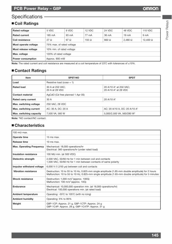
145
PCB Power Relay – G8P
Specifications Coil Ratings
Rated voltage 5 VDC 9 VDC 12 VDC 24 VDC 48 VDC 110 VDC
Rated current 185 mA 93 mA 77 mA 36 mA 19 mA 9 mA
Coil resistance 27 Ω 97 Ω 155 Ω 660 Ω 2,480 Ω 12,400 Ω
Must operate voltage 75% max. of rated voltage
Must release voltage 10% min. of rated voltage
Max. voltage 120% of rated voltage
Power consumption Approx. 900 mW
Note: The rated current and coil resistance are measured at a coil temperature of 23˚C with tolerances of ±10%.
Contact Ratings
Item SPST-NO SPDT
Load Resistive load (cosø = 1)
Rated load 30 A at 250 VAC; 20 A/10 A* at 250 VAC; 20 A at 28 VDC 20 A/10 A* at 28 VDC
Contact material AgCdO (Cd free planned 1 Apr 05)
Rated carry current 30 A 20 A/10 A*
Max. switching voltage 250 VAC, 28 VDC
Max. switching current AC: 30 A, DC: 20 A AC: 20 A/10 A, DC: 20 A/10 A*
Max. switching capacity 7,500 VA, 560 W 5,000/2,500 VA, 560/280 W*
Note: *NO contact/NC contact.
Characteristics
100 mΩ max.
Operate time 15 ms max.
Release time 10 ms max.
Max. Operating Frequency Mechanical: 18,000 operations/hrElectrical: 360 operations/hr (under rated load)
Insulation resistance 100 MΩ min. (at 500 VDC)
Dielectric strength 2,500 VAC, 50/60 Hz for 1 min between coil and contacts1,500 VAC, 50/60 Hz for 1 min between contacts of same polarity
Impulse withstand voltage 6,000 V (1.2/50 µs) between coil and contacts
Vibration resistance Destruction: 10 to 55 to 10 Hz, 0.825-mm single amplitude (1.65-mm double amplitude) for 2 hoursMalfunction: 10 to 55 to 10 Hz, 0.825-mm single amplitude (1.65-mm double amplitude) for 5 minutes
Shock resistance Destruction: 1,000 m/s2 (approx. 100G)Malfunction: 100 m/s2 (approx. 10G)
Endurance Mechanical: 10,000,000 operation min. (at 18,000 operations/hr)Electrical: 100,000 operations min. (at rated load)
Ambient temperature Operating: -55˚C to 105˚C (with no icing)
Ambient humidity Operating: 5% to 85%
Weight G8P-1CP: Approx. 21 g, G8P-1CTP: Approx. 24 gG8P-1C4P: Approx. 28 g, G8P-1C4TP: Approx. 31 g
Pow
er R
elay
s
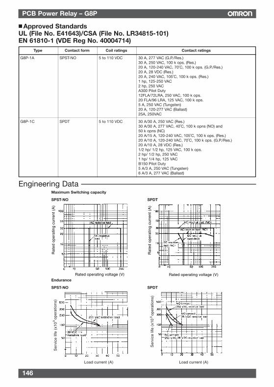
PCB Power Relay – G8P
Approved StandardsUL (File No. E41643)/CSA (File No. LR34815-101)EN 61810-1 (VDE Reg No. 40004714)
Engineering Data
Rat
ed o
pera
ting
curr
ent
(A)
Rat
ed o
pera
ting
curr
ent
(A)
Rated operating voltage (V) Rated operating voltage (V)
Ser
vice
life
(x1
03 o
pera
tions
)
Ser
vice
life
(x1
03
oper
atio
ns)
Load current (A) Load current (A)
Maximum Switching capacity
SPST-NO SPDT
Endurance
SPST-NO SPDT
146
Type Contact form Coil ratings Contact ratings
G8P-1A SPST-NO 5 to 110 VDC 30 A, 277 VAC (G.P./Res.)30 A, 250 VAC, 100 k ops. (Res.)20 A, 120-240 VAC, 70˚C, 100 k ops. (G.P./Res.)20 A, 28 VDC (Res.)20 A, 240 VAC, 105˚C, 100 k ops. (Res.)1 hp, 125-250 VAC2 hp, 250 VACA300 Pilot Duty12FLA/72LRA, 250 VAC, 100 k ops.20 FLA/96 LRA, 125 VAC, 100 k ops.5 A, 250 VAC (Tungsten)20 A, 120-277 VAC (Ballast)25A, 250VAC
G8P-1C SPDT 5 to 110 VDC 30 A/30 A, 250 VAC (Res.)30 A/30 A, 277 VAC, 40˚C, 100 k opns (NO) and 50 k opns (NC)20 A/15 A, 120-240 VAC, 105˚C, 100 k ops. (Res.)20 A/10 A, 120-240 VAC, 70˚C, 100 k ops. (G.P./Res.)20 A/10 A, 28 VDC (Res.)1/2 hp/ 1/2 hp, 125 VAC, 100 k ops.2 hp/ 1/2 hp, 250 VAC1 hp/ 1/4 hp, 125 VACB150 Pilot Duty5 A/3 A, 250 VAC (Tungsten)6 A/3 A, 277 VAC (Ballast)
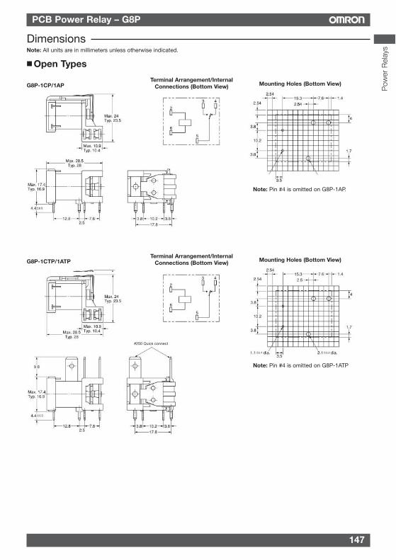
147
PCB Power Relay – G8P
DimensionsNote: All units are in millimeters unless otherwise indicated.
Open Types
G8P-1CP/1APTerminal Arrangement/Internal
Connections (Bottom View) Mounting Holes (Bottom View)
Note: Pin #4 is omitted on G8P-1AP.
G8P-1CTP/1ATPTerminal Arrangement/Internal
Connections (Bottom View) Mounting Holes (Bottom View)
Note: Pin #4 is omitted on G8P-1ATP
#250 Quick connect
Pow
er R
elay
s
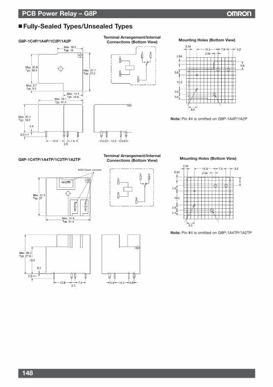
148
PCB Power Relay – G8P
Fully-Sealed Types/Unsealed Types
Mounting Holes (Bottom View)Terminal Arrangement/Internal
Connections (Bottom View)G8P-1C4P/1A4P/1C2P/1A2P
G8P-1C4TP/1A4TP/1C2TP/1A2TP
#250 Quick connect
Terminal Arrangement/InternalConnections (Bottom View) Mounting Holes (Bottom View)
Note: Pin #4 is omitted on G8P-1A4P/1A2P
Note: Pin #4 is omitted on G8P-1A4TP/1A2TP
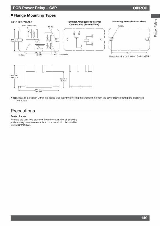
149
PCB Power Relay – G8P
Precautions
Flange Mounting Types
Note: Pin #4 is omitted on G8P-1A2T-F
Note: Allow air circulation within the sealed type G8P by removing the knock off nib from the cover after soldering and cleaning iscomplete.
G8P-1C2T-F/1A2T-F Terminal Arrangement/InternalConnections (Bottom View)
Mounting Holes (Bottom View)
#187 Quick connect
#250 Quick connect
Sealed RelaysRemove the vent hole tape seal from the cover after all solderingand cleaning have been completed to allow air circulation withinsealed G8P Relays.
Pow
er R
elay
s
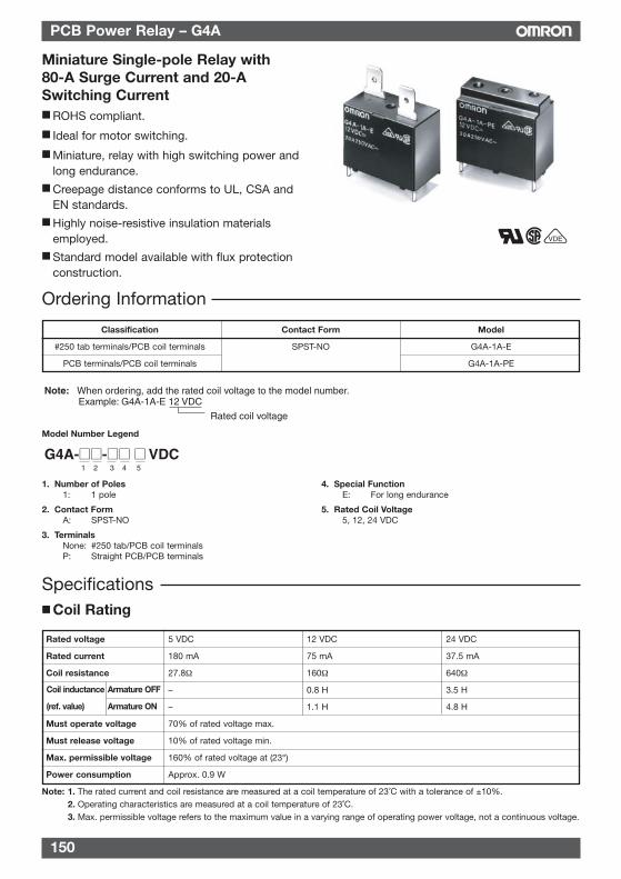
150
PCB Power Relay – G4A
Miniature Single-pole Relay with80-A Surge Current and 20-ASwitching Current ROHS compliant.
Ideal for motor switching.
Miniature, relay with high switching power andlong endurance.
Creepage distance conforms to UL, CSA andEN standards.
Highly noise-resistive insulation materialsemployed.
Standard model available with flux protectionconstruction.
VDE
Rated coil voltage
Note: When ordering, add the rated coil voltage to the model number. Example: G4A-1A-E 12 VDC
G4A-- VDC1 2 3 4 5
Rated voltage 5 VDC 12 VDC 24 VDC
Rated current 180 mA 75 mA 37.5 mA
Coil resistance 27.8Ω 160Ω 640Ω
– 0.8 H 3.5 H
– 1.1 H 4.8 H
Must operate voltage 70% of rated voltage max.
Must release voltage 10% of rated voltage min.
Max. permissible voltage 160% of rated voltage at (23°)
Power consumption Approx. 0.9 W
Note: 1. The rated current and coil resistance are measured at a coil temperature of 23˚C with a tolerance of ±10%.2. Operating characteristics are measured at a coil temperature of 23˚C.3. Max. permissible voltage refers to the maximum value in a varying range of operating power voltage, not a continuous voltage.
Specifications Coil Rating
Coil inductance Armature OFF
(ref. value) Armature ON
Ordering Information
Classification Contact Form Model
#250 tab terminals/PCB coil terminals SPST-NO G4A-1A-E
PCB terminals/PCB coil terminals G4A-1A-PE
Model Number Legend
1. Number of Poles1: 1 pole
2. Contact FormA: SPST-NO
3. TerminalsNone: #250 tab/PCB coil terminalsP: Straight PCB/PCB terminals
4. Special FunctionE: For long endurance
5. Rated Coil Voltage5, 12, 24 VDC
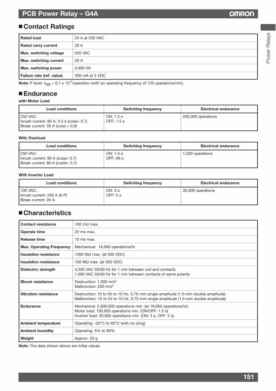
151
PCB Power Relay – G4A
Characteristics
Contact resistance 100 mΩ max.
Operate time 20 ms max.
Release time 10 ms max.
Max. Operating Frequency Mechanical: 18,000 operations/hr
Insulation resistance 1000 MΩ max. (at 500 VDC)
Insulation resistance 100 MΩ max. (at 500 VDC)
Dielectric strength 4,500 VAC 50/60 Hz for 1 min between coil and contacts1,000 VAC 50/60 Hz for 1 min between contacts of same polarity
Shock resistance Destruction: 1,000 m/s2
Malfunction: 200 m/s2
Vibration resistance Destruction: 10 to 55 to 10 Hz, 0.75-mm single amplitude (1.5-mm double amplitude)Malfunction: 10 to 55 to 10 Hz, 0.75-mm single amplitude (1.5-mm double amplitude)
Endurance Mechanical: 2,000,000 operations min. (at 18,000 operations/hr)Motor load: 100,000 operations min. (ON/OFF: 1.5 s)Inverter load: 30,000 operations min. (ON: 3 s, OFF: 5 s)
Ambient temperature Operating: -20°C to 60°C (with no icing)
Ambient humidity Operating: 5% to 85%
Weight Approx. 25 g
Note: The data shown above are initial values.
Contact Ratings
Rated load 20 A at 250 VAC
Rated carry current 20 A
Max. switching voltage 250 VAC
Max. switching current 20 A
Max. switching power 5,000 VA
Failure rate (ref. value) 100 mA at 5 VDC
Note: P level: λ60 = 0.1 x 10⁻⁶/operation (with an operating frequency of 120 operations/min).
Endurancewith Motor Load
Load conditions Switching frequency Electrical endurance
250 VAC: ON: 1.5 s 200,000 operationsInrush current: 80 A, 0.3 s (cosø= 0.7) OFF: 1.5 sBreak current: 20 A (cosø = 0.9)
With Overload
Load conditions Switching frequency Electrical endurance
250 VAC: ON: 1.5 s 1,500 operationsInrush current: 80 A (cosø= 0.7) OFF: 99 sBreak current: 80 A (cosfø= 0.7)
With Inverter Load
Load conditions Switching frequency Electrical endurance
100 VAC: ON: 3 s 30,000 operationsInrush current: 200 A (0-P) OFF: 5 sBreak current: 20 A
Pow
er R
elay
s
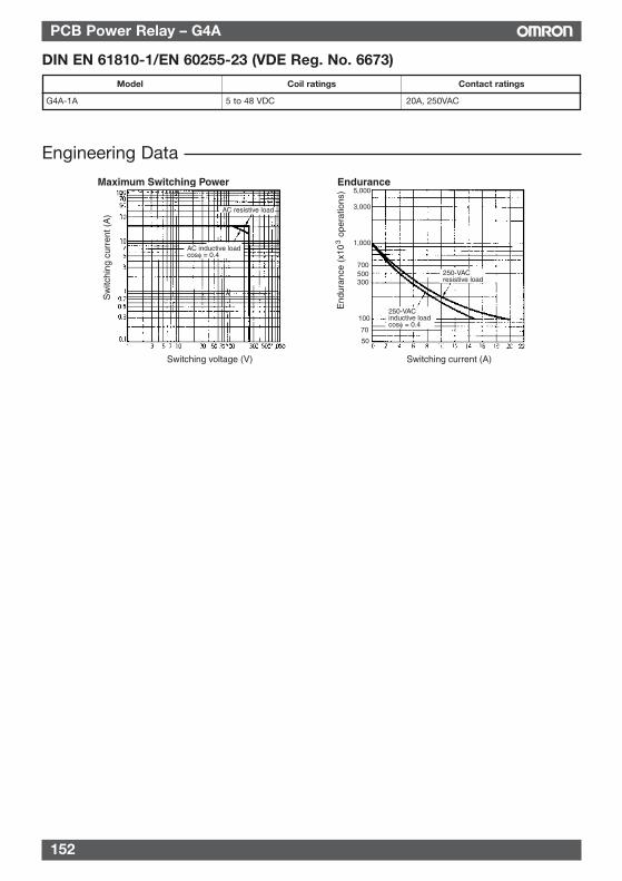
152
PCB Power Relay – G4A
Engineering Data
Maximum Switching Power Endurance
Sw
itchi
ng c
urre
nt (
A)
End
uran
ce (
x10
ope
ratio
ns)
3
Switching voltage (V) Switching current (A)
AC resistive load
AC inductive loadcosφ = 0.4
250-VACresistive load
250-VACinductive loadcosφ = 0.4
5,000
3,000
1,000
700 500 300
100
70
50
DIN EN 61810-1/EN 60255-23 (VDE Reg. No. 6673)
Model Coil ratings Contact ratings
G4A-1A 5 to 48 VDC 20A, 250VAC
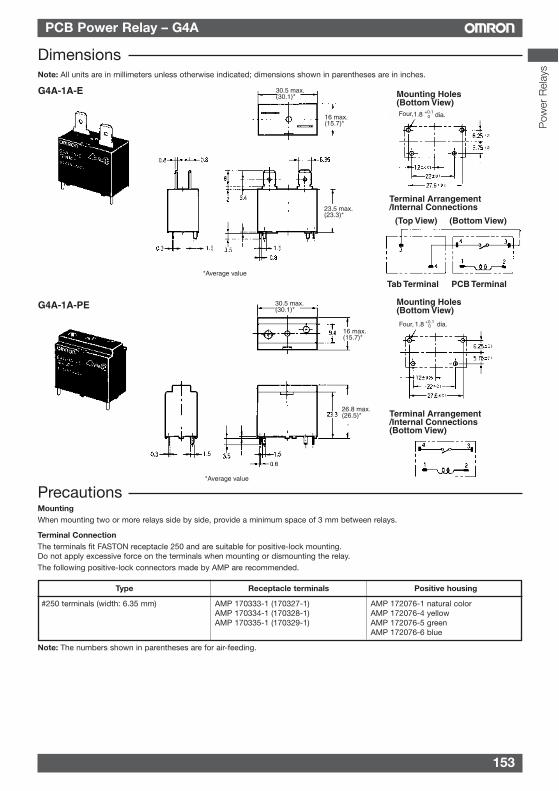
153
PCB Power Relay – G4A
PrecautionsMountingWhen mounting two or more relays side by side, provide a minimum space of 3 mm between relays.
Terminal ConnectionThe terminals fit FASTON receptacle 250 and are suitable for positive-lock mounting.Do not apply excessive force on the terminals when mounting or dismounting the relay.The following positive-lock connectors made by AMP are recommended.
Type Receptacle terminals Positive housing
#250 terminals (width: 6.35 mm) AMP 170333-1 (170327-1) AMP 172076-1 natural colorAMP 170334-1 (170328-1) AMP 172076-4 yellowAMP 170335-1 (170329-1) AMP 172076-5 green
AMP 172076-6 blue
Note: The numbers shown in parentheses are for air-feeding.
DimensionsNote: All units are in millimeters unless otherwise indicated; dimensions shown in parentheses are in inches.
Terminal Arrangement/Internal Connections
G4A-1A-E Mounting Holes(Bottom View)
30.5 max.(30.1)*
16 max.(15.7)*
23.5 max.(23.3)*
(Top View) (Bottom View)
Tab Terminal PCB Terminal
Four, 1.8 +0.10 dia.
Four, 1.8 +0.10 dia.
16 max.(15.7)*
26.8 max.(26.5)*
30.5 max.(30.1)*G4A-1A-PE
Terminal Arrangement/Internal Connections(Bottom View)
Mounting Holes(Bottom View)
*Average value
*Average value
Pow
er R
elay
s
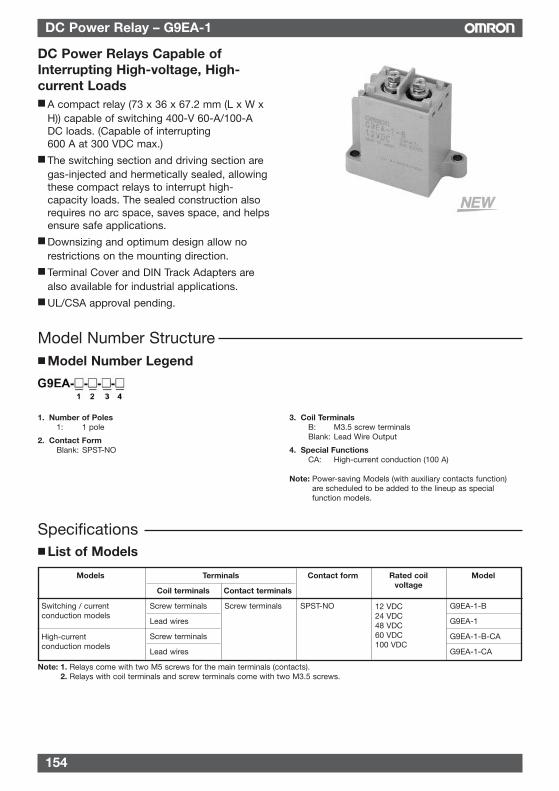
154
DC Power Relay – G9EA-1
Models Terminals Contact form Model
Coil terminals Contact terminals
Screw terminals Screw terminals SPST-NO G9EA-1-B
Lead wires G9EA-1
Screw terminals G9EA-1-B-CA
Lead wires G9EA-1-CA
Note: 1. Relays come with two M5 screws for the main terminals (contacts).2. Relays with coil terminals and screw terminals come with two M3.5 screws.
List of Models
Rated coilvoltage
12 VDC24 VDC48 VDC60 VDC100 VDC
Switching / currentconduction models
High-currentconduction models
DC Power Relays Capable ofInterrupting High-voltage, High-current Loads A compact relay (73 x 36 x 67.2 mm (L x W x
H)) capable of switching 400-V 60-A/100-ADC loads. (Capable of interrupting600 A at 300 VDC max.)
The switching section and driving section aregas-injected and hermetically sealed, allowingthese compact relays to interrupt high-capacity loads. The sealed construction alsorequires no arc space, saves space, and helpsensure safe applications.
Downsizing and optimum design allow norestrictions on the mounting direction.
Terminal Cover and DIN Track Adapters arealso available for industrial applications.
UL/CSA approval pending.
1. Number of Poles1: 1 pole
2. Contact FormBlank: SPST-NO
3. Coil TerminalsB: M3.5 screw terminalsBlank: Lead Wire Output
4. Special FunctionsCA: High-current conduction (100 A)
Note: Power-saving Models (with auxiliary contacts function)are scheduled to be added to the lineup as specialfunction models.
Specifications
Model Number Structure Model Number Legend
155
DC Power Relay – G9EA-1
Rated voltage Rated current Coil resistance Must-operate Must-release Max. Voltage Powervoltage voltage (see note 3) consumption
12 VDC 417 mA 28.8 Ω Approx. 5 W
24 VDC 208 mA 115.2 Ω
48 VDC 102 mA 469.3 Ω
60 VDC 86.2 mA 695.7 Ω Approx. 5.2 W
100 VDC 53.6 mA 1,864 Ω Approx. 5.4 W
Note: 1. The figures for the rated current and coil resistance are for a coil temperature of 23°C and have a tolerance of ±10%.2. The figures for the operating characteristics are for a coil temperature of 23°C.3. The figure for the maximum voltage is the maximum voltage that can be applied to the relay coil for period of 10 minutes at
an ambient temperature of 23°C. It does not apply to continuous operation.
130% of ratedvoltage
8% min. of ratedvoltage
75% max. ofrated voltage
Contacts
Item Rated current
G9EA-1(-B) G9EA-1(-B)-CA
Rated load 60 A at 400 VDC, 100 A at 120 VDC 30 A at 400 VDC
Rated carry current 60 A 100 A
Maximum switching voltage 400 V 400 V
Maximum switching current 100 A 30 A
RatingsCoil
Pow
er R
elay
s
156
DC Power Relay – G9EA-1
Characteristics
Item G9EA-1(-B) G9EA-1(-B)-CA
Contact resistance (see note 2) 30 mΩ max. (0.6 mΩ typical) 10 mΩ max. (0.3 mΩ typical)
Contact voltage drop 0.1 V max. 0.1 V max.(for a carry current of 60 A) (for a carry current of 100 A)
Operate time 50 ms max.
Release time 30 ms max.
Between coil & contacts 1,000 MΩ min.
Between contacts of the same polarity 1,000 MΩ min.
Dielectric strength Between coil & contacts 2,500 VAC, 1 min
Between contacts of the same polarity 2,500 VAC, 1 min
Impulse withstand voltage (See note 4.) 4,500 V
Vibration resistance Destruction 10 to 55 to 10 Hz, 0.75-mm single amplitude(Acceleration: 2.94 to 88.9 m/s2)
Malfunction 10 to 55 to 10 Hz, 0.75-mm single amplitude(Acceleration: 2.94 to 88.9 m/s2)
Shock resistance Destruction 490 m/s2
Malfunction 196 m/s2
Mechanical endurance (See note 5.) 200,000 ops. min.
Electrical endurance (See note 6.) 120 VDC, 100 A, 3,000 ops. min. 400 VDC, 30 A, 1,000 ops. min.
400 VDC, 60 A, 3,000 ops. min. 120 VDC, 30 A, 2,500 ops. min.
400 VDC, 30 A, 30,000 ops. min. –
Short-time carry current 100 A (10 min) 150 A (10 min)
Maximum interruption current 600 A at 300 VDC (5 times) –
Overload interruption 180 A at 400 VDC 100 A at 120 VDC (100 times min.) (150 times min.)
Reverse polarity interruption -60 A at 200 VDC –(1,000 times min.)
Ambient operating temperature -40 to 70°C (with no icing or condensation)
Ambient operating humidity 5% to 85%
Weight Approx. 310 g
Note: 1. The above values are initial values at an ambient temperature of 23°C unless otherwise specified.2. The contact resistance was measured with 1 A at 5 VDC using the voltage drop method.3. The insulation resistance was measured with a 500-VDC megohmmeter.4. The impulse withstand voltage was measured with a JEC-212 (1981) standard impulse voltage waveform (1.2 x 50 µs).5. The mechanical endurance was measured at a switching frequency of 3,600 operations/hr.6. The electrical endurance was measured at a switching frequency of 60 operations/hr.
Insulation resistance(see note 3.)
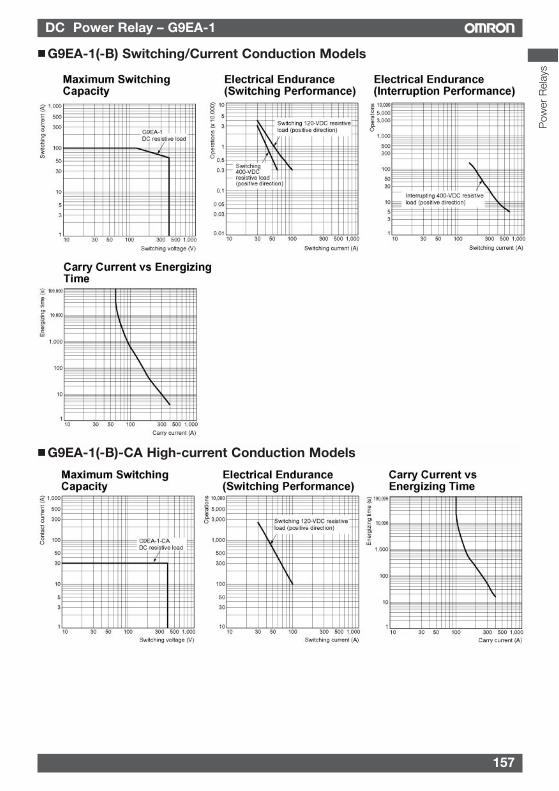
157
DC Power Relay – G9EA-1
G9EA-1(-B)-CA High-current Conduction Models
G9EA-1(-B) Switching/Current Conduction Models
Pow
er R
elay
s
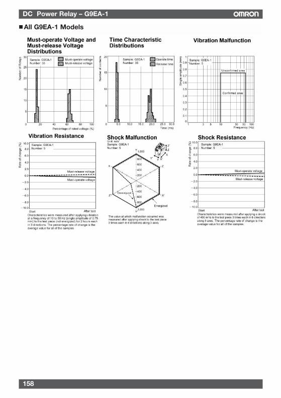
158
DC Power Relay – G9EA-1
All G9EA-1 Models
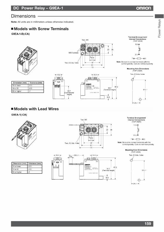
159
DC Power Relay – G9EA-1
Models with Screw Terminals
DimensionsNote: All units are in millimeters unless otherwise indicated.
Models with Lead Wires
Pow
er R
elay
s
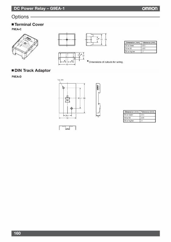
160
DC Power Relay – G9EA-1
Options Terminal Cover
DIN Track Adaptor
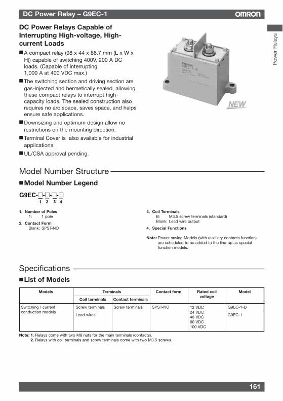
161
DC Power Relay – G9EC-1
Models Terminals Contact form Model
Coil terminals Contact terminals
Screw terminals Screw terminals SPST-NO G9EC-1-B
Lead wires G9EC-1
Note: 1. Relays come with two M8 nuts for the main terminals (contacts).2. Relays with coil terminals and screw terminals come with two M3.5 screws.
List of Models
Rated coilvoltage
12 VDC24 VDC48 VDC60 VDC100 VDC
Switching / currentconduction models
DC Power Relays Capable ofInterrupting High-voltage, High-current Loads A compact relay (98 x 44 x 86.7 mm (L x W x
H)) capable of switching 400V, 200 A DCloads. (Capable of interrupting1,000 A at 400 VDC max.)
The switching section and driving section aregas-injected and hermetically sealed, allowingthese compact relays to interrupt high-capacity loads. The sealed construction alsorequires no arc space, saves space, and helpsensure safe applications.
Downsizing and optimum design allow norestrictions on the mounting direction.
Terminal Cover is also available for industrialapplications.
UL/CSA approval pending.
1. Number of Poles1: 1 pole
2. Contact FormBlank: SPST-NO
3. Coil TerminalsB: M3.5 screw terminals (standard)Blank: Lead wire output
4. Special Functions
Note: Power-saving Models (with auxiliary contacts function)are scheduled to be added to the line-up as specialfunction models.
Specifications
Model Number Structure Model Number Legend
Pow
er R
elay
s
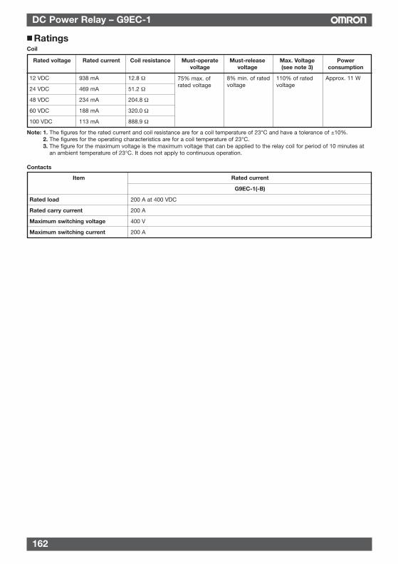
Rated voltage Rated current Coil resistance Must-operate Must-release Max. Voltage Powervoltage voltage (see note 3) consumption
12 VDC 938 mA 12.8 Ω Approx. 11 W
24 VDC 469 mA 51.2 Ω
48 VDC 234 mA 204.8 Ω
60 VDC 188 mA 320.0 Ω
100 VDC 113 mA 888.9 Ω
Note: 1. The figures for the rated current and coil resistance are for a coil temperature of 23°C and have a tolerance of ±10%.2. The figures for the operating characteristics are for a coil temperature of 23°C.3. The figure for the maximum voltage is the maximum voltage that can be applied to the relay coil for period of 10 minutes at
an ambient temperature of 23°C. It does not apply to continuous operation.
110% of ratedvoltage
8% min. of ratedvoltage
75% max. ofrated voltage
Contacts
Item Rated current
G9EC-1(-B)
Rated load 200 A at 400 VDC
Rated carry current 200 A
Maximum switching voltage 400 V
Maximum switching current 200 A
RatingsCoil
162
DC Power Relay – G9EC-1
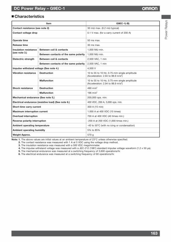
DC Power Relay – G9EC-1
163
Characteristics
Item G9EC-1(-B)
Contact resistance (see note 2) 30 mΩ max. (0.2 mΩ typical)
Contact voltage drop 0.1 V max. (for a carry current of 200 A)
Operate time 50 ms max.
Release time 30 ms max.
Between coil & contacts 1,000 MΩ min.
Between contacts of the same polarity 1,000 MΩ min.
Dielectric strength Between coil & contacts 2,500 VAC, 1 min
Between contacts of the same polarity 2,500 VAC, 1 min
Impulse withstand voltage (See note 4.) 4,500 V
Vibration resistance Destruction 10 to 55 to 10 Hz, 0.75-mm single amplitude(Acceleration: 2.94 to 88.9 m/s2)
Malfunction 10 to 55 to 10 Hz, 0.75-mm single amplitude(Acceleration: 2.94 to 88.9 m/s2)
Shock resistance Destruction 490 m/s2
Malfunction 196 m/s2
Mechanical endurance (See note 5.) 200,000 ops. min.
Electrical endurance (resistive load) (See note 6.) 400 VDC, 200 A, 3,000 ops. min.
Short-time carry current 300 A (15 min)
Maximum interruption current 1.000 A at 400 VDC (10 times)
Overload interruption 700 A at 400 VDC (40 times min.)
Reverse polarity interruption -200 A at 200 VDC (1,000 times min.)
Ambient operating temperature -40 to 50°C (with no icing or condensation)
Ambient operating humidity 5% to 85%
Weight Approx. 570 g
Note: 1. The above values are initial values at an ambient temperature of 23°C unless otherwise specified.2. The contact resistance was measured with 1 A at 5 VDC using the voltage drop method.3. The insulation resistance was measured with a 500 VDC megohmmeter.4. The impulse withstand voltage was measured with a JEC-212 (1981) standard impulse voltage waveform (1.2 x 50 µs).5. The mechanical endurance was measured at a switching frequency of 3,600 operations/hr.6. The electrical endurance was measured at a switching frequency of 60 operations/hr.
Insulation resistance(see note 3.)
Pow
er R
elay
s
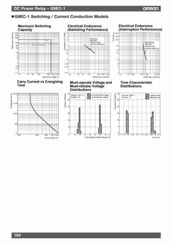
G9EC-1 Switching / Current Conduction Models
164
DC Power Relay – G9EC-1
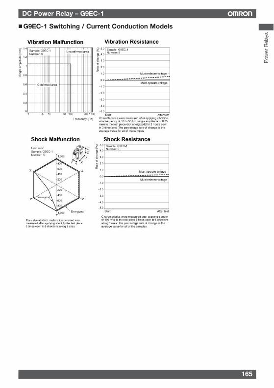
DC Power Relay – G9EC-1
165
G9EC-1 Switching / Current Conduction Models
Pow
er R
elay
s
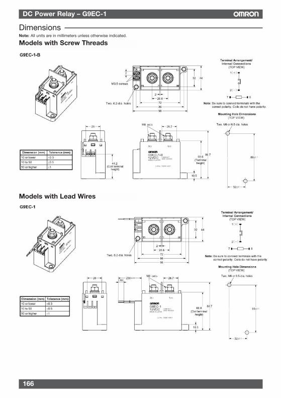
DimensionsNote: All units are in millimeters unless otherwise indicated.
Models with Screw Threads
Models with Lead Wires
166
DC Power Relay – G9EC-1
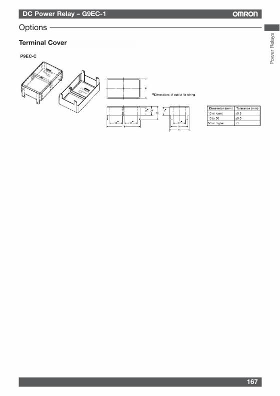
DC Power Relay – G9EC-1
167
Terminal Cover
Options
Pow
er R
elay
s
168
DC Power Relay – G9EC-1
PrecautionsWARNINGTake measures to prevent contact with charged partswhen using the Relay for high voltages.
Correct UseRefer to the relevant catalog for common precautions.
1. Be sure to tighten all screws to the appropriate torque givenbelow. Loose screws may result in burning due to abnormalheat generation during energization.• M8 screws: 8.82 to 9.80 N·m
• M6 screws: 3.92 to 4.90 N·m
• M5 screws: 1.57 to 2.35 N·m
• M4 screws: 0.98 to 1.37 N·m
• M3.5 screws: 0.75 to 1.18 N·m
2. The G9EA and G9EC Relays’ contacts have polarity. Be sureto perform connections with the correct polarity. If thecontacts are connected with the reverse polarity, theswitching characteristics specified in this document cannotbe assured.
3. Do not drop or disassemble this Relay. Not only may theRelay fail to meet the performance specifications, it mayalso result in damage, electric shock, or burning.
4. Do not use these Relays in strong magnetic fields of 800A/m or higher (e.g., near transformers or magnets). The arcdischarge that occurs during switching may be bent by themagnetic field, resulting in flashover or insulation faults.
5. This Relay is a device for switching high DC voltages. If it isused for voltages exceeding the specified range, it may notbe possible to interrupt the load and burning may result. Inorder to prevent fire spreading, use a configuration in whichthe current load can be interrupted in the event ofemergencies.
In order to ensure safety of the system, replace the Relay ona regular basis.
6. If the Relay is used for no-load switching, the contactresistance may increase and so confirm correct operationunder the actual operating conditions.
7. These Relays contain pressurized gas. Even in applicationswith low switching frequencies, the ambient temperatureand heat caused by arc discharge in the contacts may allowpermeation of the sealed gas, resulting in arc interruptionfailure.
In order to ensure safety of the system, replace Relays on aregular basis.
8. Do not use or store the Relay in a vacuum. Doing so willaccelerate deterioration of the sealing.
9. With this Relay, if the rated voltage (or current) iscontinuously applied to the coil and contacts, and thenturned OFF and immediately ON again, the coil temperature,and consequently the coil resistance, will be higher thanusual. This means that the mustoperate voltage will also behigher than usual, exceeding the rated value (“hot start”). Inthis case, take the appropriate countermeasures, such asreducing the load current or restricting the energizing time orambient operating temperature.
10. The ripple percentage for DC relays can cause fluctuationsin the must-operate voltage or humming. For this reason,reduce the ripple percentage in full-wave rectified powersupply circuits by adding a smoothing capacitor. Ensure thatthe ripple percentage is less than 5%.
11. Ensure that a voltage exceeding the specified maximumvoltage is not continuously applied to the coil. Abnormalheating in the coil may shorten the lifetime of the insulationcoating.
12. Do not use the Relay at a switching voltage or currentgreater than the specified maximum values. Doing so mayresult in arc discharge interruption failure or burning due toabnormal heating in the contacts.
13. The contact ratings are for resistive loads. The electricalendurance with inductive loads is inferior to that of resistiveloads. Confirm correct operation under the actual operatingconditions.
14. Do not use the Relay in locations where water, solvents,chemicals, or oil may come in contact with the case orterminals. Doing so may result in deterioration of the caseresin or abnormal heating due to corrosion or contaminationof the terminals. Also, if electrolyte adheres to the outputterminals, electrolysis may occur between the outputterminals, resulting in corrosion of the terminals or wiringdisconnections.
15. Be sure to turn OFF the power and confirm that there is noresidual voltage before replacing the Relay or performingwiring.
16. The distance between crimp terminals or other conductiveparts will be reduced and insulation properties will belowered if wires are laid in the same direction from thecontact terminals. Use insulating coverings, do not wire inthe same direction, and take other measures as required tomaintain insulation properties.
17. Do not tighten the screws to a torque exceeding 11 N·m forthe M8 screws and 5 N·m for the M5 screws.
Overtightening the contact terminals will reduce theswitching performance and damage the product.
The coil’s power consumption can be reduced by using incombination with a semiconductor circuit. Consult your OMRONrepresentative for details.
Recommended Wire Size
Note: Use flexible leads.
Model Size
G9EA-1(-B) 14 to 22 mm2
G9EA-1(-B)-CA 22 to 38 mm2
G9EC-1(-B) 38 to 60 mm2
G9EB-1-B Consult your OMRON representative
ALL DIMENSIONS SHOWN ARE IN MILLIMETERS.To convert millimeters into inches, multiply by 0.03937. To convert grams into ounces, multiply by 0.03527.