Embed Size (px)
Citation preview

Technical Information
Standard Use Environment
Degree of Protection
Power Losses & Resistance
Cascading Table
Installation
Standard Configuration
MCCB/ELCB Assembly and Terminal Mounting Specification
54
57
58
60
64
66
67
Technical Information
Standard Use Environment
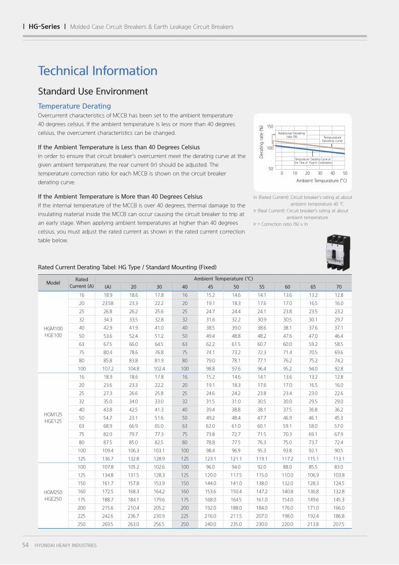
Temperature DeratingOvercurrent characteristics of MCCB has been set to the ambient temperature
40 degrees celsius. If the ambient temperature is less or more than 40 degrees
celsius, the overcurrent characteristics can be changed.
If the Ambient Temperature is Less than 40 Degrees Celsius
In order to ensure that circuit breaker's overcurrent meet the derating curve at the
given ambient temperature, the rear current (Ir) should be adjusted. The
temperature correction ratio for each MCCB is shown on the circuit breaker
derating curve.
If the Ambient Temperature is More than 40 Degrees Celsius
If the internal temperature of the MCCB is over 40 degrees, thermal damage to the
insulating material inside the MCCB can occur causing the circuit breaker to trip at
an early stage. When applying ambient temperatures at higher than 40 degrees
celsius, you must adjust the rated current as shown in the rated current correction
table below.
ModelRated
Current (A)
Ambient Temperature (℃)
(A) 20 30 40 45 50 55 60 65 70
HGM100
HGE100
16 18.9 18.6 17.8 16 15.2 14.6 14.1 13.6 13.2 12.8
20 23.58 23.3 22.2 20 19.1 18.3 17.6 17.0 16.5 16.0
25 26.8 26.2 25.6 25 24.7 24.4 24.1 23.8 23.5 23.2
32 34.3 33.5 32.8 32 31.6 32.2 30.9 30.5 30.1 29.7
40 42.9 41.9 41.0 40 38.5 39.0 38.6 38.1 37.6 37.1
50 53.6 52.4 51.2 50 49.4 48.8 48.2 47.6 47.0 46.4
63 67.5 66.0 64.5 63 62.2 61.5 60.7 60.0 59.2 58.5
75 80.4 78.6 76.8 75 74.1 73.2 72.3 71.4 70.5 69.6
80 85.8 83.8 81.9 80 79.0 78.1 77.1 76.2 75.2 74.2
100 107.2 104.8 102.4 100 98.8 97.6 96.4 95.2 94.0 92.8
HGM125
HGE125
16 18.9 18.6 17.8 16 15.2 14.6 14.1 13.6 13.2 12.8
20 23.6 23.3 22.2 20 19.1 18.3 17.6 17.0 16.5 16.0
25 27.3 26.6 25.8 25 24.6 24.2 23.8 23.4 23.0 22.6
32 35.0 34.0 33.0 32 31.5 31.0 30.5 30.0 29.5 29.0
40 43.8 42.5 41.3 40 39.4 38.8 38.1 37.5 36.8 36.2
50 54.7 23.1 51.6 50 49.2 48.4 47.7 46.9 46.1 45.3
63 68.9 66.9 65.0 63 62.0 61.0 60.1 59.1 58.0 57.0
75 82.0 79.7 77.3 75 73.8 72.7 71.5 70.3 69.1 67.9
80 87.5 85.0 82.5 80 78.8 77.5 76.3 75.0 73.7 72.4
100 109.4 106.3 103.1 100 98.4 96.9 95.3 93.8 92.1 90.5
125 136.7 132.8 128.9 125 123.1 121.1 119.1 117.2 115.1 113.1
HGM250
HGE250
100 107.8 105.2 102.6 100 96.0 94.0 92.0 88.0 85.5 83.0
125 134.8 131.5 128.3 125 120.0 117.5 115.0 110.0 106.9 103.8
150 161.7 157.8 153.9 150 144.0 141.0 138.0 132.0 128.3 124.5
160 172.5 168.3 164.2 160 153.6 150.4 147.2 140.8 136.8 132.8
175 188.7 184.1 179.6 175 168.0 164.5 161.0 154.0 149.6 145.3
200 215.6 210.4 205.2 200 192.0 188.0 184.0 176.0 171.0 166.0
225 242.6 236.7 230.9 225 216.0 211.5 207.0 198.0 192.4 186.8
250 269.5 263.0 256.5 250 240.0 235.0 230.0 220.0 213.8 207.5
Rated Current Derating Tabel: HG Type / Standard Mounting (Fixed)
In (Rated Current): Circuit breaker's rating at about
ambient temperature 40 ℃
Ir (Real Current): Circuit breaker's rating at about
ambient temperature
Ir = Correction ratio (%) x In
0
150
5010 20 30 40 50
주위온도 (°C)
보정비(%)
100
추가 전류 보정치 (%)
플러그인 조합 시 온도 보정 곡선
온도 보정 곡선
Ambient Tempurature (°C)
Derating rate (%)
0
150
5010 20 30 40 50
100
Additional Derating rate (%)
Tempurature Derating Curve at the Time of Plug-In Combination
TempuratureDerating curve
54 HYUNDAI HEAVY INDUSTRIES
| hg-Series | Molded Case Circuit Breakers & Earth Leakage Circuit Breakers
ModelRated
Current (A)
Ambient Temperature (℃)
10 20 30 40 45 50 55 60 65 70
HGM100
HGE100
16 18.5 18.3 17.4 16 14.9 14.3 13.8 13.3 12.9 12.5
20 23.1 22.8 21.8 20 18.7 17.9 17.2 16.7 16.1 15.7
25 26.3 25.7 25.1 25 24.2 23.9 23.6 23.3 23.0 22.7
32 33.6 32.9 32.1 31 31.0 31.6 30.2 29.9 29.5 29.1
40 42.0 41.1 40.1 39 37.7 38.3 37.8 37.3 36.8 36.4
50 52.5 51.4 50.2 49 48.4 47.8 47.2 46.6 46.1 45.5
63 66.2 64.7 63.2 62 61.0 60.3 59.5 58.8 58.0 57.3
75 78.8 77.0 75.3 74 72.6 71.7 70.9 70.0 69.1 68.2
80 84.0 82.2 80.3 78 77.5 76.5 75.6 74.6 73.7 72.8
100 105.1 102.7 100.4 98 96.8 95.6 94.5 93.3 92.1 90.9
HGM125
HGE125
16 18.5 18.2 17.4 16 14.9 14.3 13.8 13.3 12.9 12.5
20 23.1 22.8 21.8 20 18.7 17.9 17.2 16.7 16.1 15.7
25 26.8 26.0 25.3 25 24.1 23.7 23.4 23.0 22.6 22.2
32 34.3 33.3 32.3 31 30.9 30.4 29.9 29.4 28.9 28.4
40 42.9 41.7 40.4 39 38.6 38.0 37.4 36.8 36.1 35.5
50 53.6 22.7 50.5 49 48.2 47.5 46.7 45.9 45.1 44.4
63 67.5 65.6 63.7 62 60.8 59.8 58.8 57.9 56.9 55.9
75 80.4 78.1 75.8 74 72.4 71.2 70.1 68.9 67.7 66.5
80 85.8 83.3 80.9 78 77.2 76.0 74.7 73.5 72.2 71.0
100 107.2 104.1 101.1 98 96.5 94.9 93.4 91.9 90.2 88.7
125 134.0 130.2 126.3 123 120.6 118.7 116.8 114.8 112.8 110.9
HGM250
HGE250
100 103.5 101.0 98.5 96 92.2 90.2 88.3 84.5 82.1 79.7
125 129.4 126.2 123.1 120 115.2 112.8 110.4 105.6 102.6 99.6
150 155.3 151.5 147.8 144 138.2 135.4 132.5 126.7 123.1 119.5
160 165.6 161.6 157.6 154 147.5 144.4 141.3 135.2 131.3 127.5
175 181.1 176.7 172.4 168 161.3 157.9 154.6 147.8 143.6 139.4
200 207.0 202.0 197.0 192 184.3 180.5 176.6 169.0 164.2 159.4
225 232.9 227.3 221.6 216 207.4 203.0 198.7 190.1 184.7 179.3
250 258.7 252.5 246.2 240 230.4 225.6 220.8 211.2 205.2 199.2
HGM400
HGE400
250 261.4 255.1 248.8 242.5 239.3 236.2 233.0 229.9 226.6 223.4
300 314.3 307.0 299.7 291.0 282.3 273.5 264.8 256.1 247.4 238.6
350 366.7 358.2 349.7 339.5 329.8 320.1 310.4 300.7 291.0 281.3
400 405.2 395.8 387.6 378 373.7 367.9 363.2 357.9 352.6 347.3
HGM630/800
HGE630/800
500 523.8 511.7 499.6 485.0 470.5 455.9 441.4 426.8 412.3 397.7
630 660.0 644.7 629.4 611.1 592.7 574.2 555.8 537.4 519.0 500.5
700 725.8 709.0 692.2 672.0 651.8 631.7 611.5 591.4 571.2 551.0
800 777.8 759.7 744.1 726 717.4 706.3 697.3 687 676.9 666.7
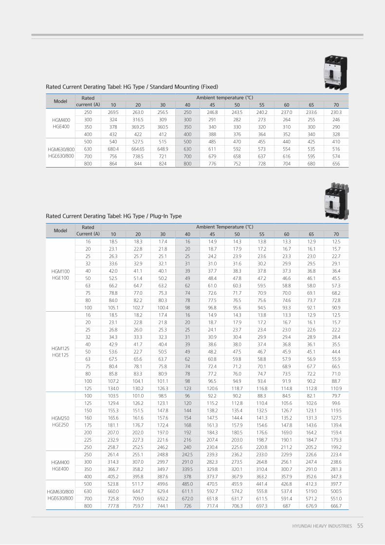
Rated Current Derating Tabel: HG Type / Plug-In Type
ModelRated
current (A)
Ambient temperature (℃)
10 20 30 40 45 50 55 60 65 70
HGM400
HGE400
250 269.5 263.0 256.5 250 246.8 243.5 240.2 237.0 233.6 230.3
300 324 316.5 309 300 291 282 273 264 255 246
350 378 369.25 360.5 350 340 330 320 310 300 290
400 432 422 412 400 388 376 364 352 340 328
HGM630/800
HGE630/800
500 540 527.5 515 500 485 470 455 440 425 410
630 680.4 664.65 648.9 630 611 592 573 554 535 516
700 756 738.5 721 700 679 658 637 616 595 574
800 864 844 824 800 776 752 728 704 680 656
Rated Current Derating Tabel: HG Type / Standard Mounting (Fixed)
55HYUNDAI HEAVY INDUSTRIES
Technical Information
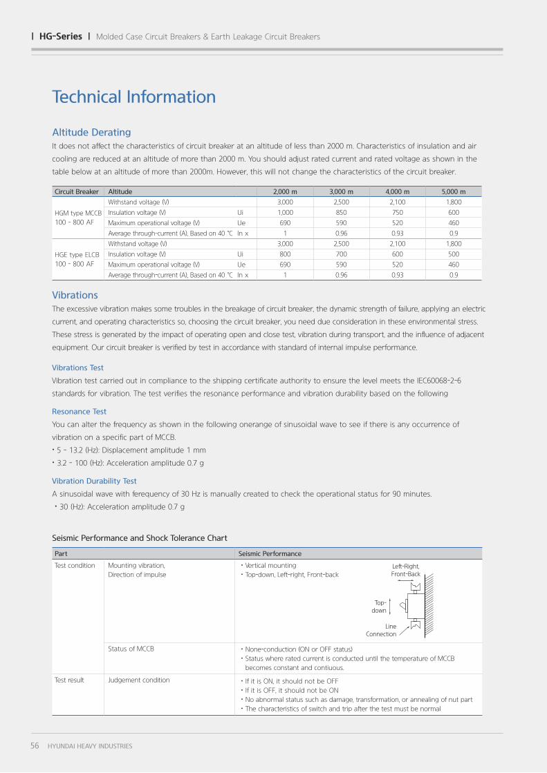
Circuit Breaker Altitude 2,000 m 3,000 m 4,000 m 5,000 m
HGM type MCCB
100 - 800 AF
Withstand voltage (V) 3,000 2,500 2,100 1,800
Insulation voltage (V) Ui 1,000 850 750 600
Maximum operational voltage (V) Ue 690 590 520 460
Average through-current (A), Based on 40 ℃ ln x 1 0.96 0.93 0.9
HGE type ELCB
100 - 800 AF
Withstand voltage (V) 3,000 2,500 2,100 1,800
Insulation voltage (V) Ui 800 700 600 500
Maximum operational voltage (V) Ue 690 590 520 460
Average through-current (A), Based on 40 ℃ ln x 1 0.96 0.93 0.9
Vibrations Test
Vibration test carried out in compliance to the shipping certificate authority to ensure the level meets the IEC60068-2-6
standards for vibration. The test verifies the resonance performance and vibration durability based on the following
Resonance Test
You can alter the frequency as shown in the following onerange of sinusoidal wave to see if there is any occurrence of
vibration on a specific part of MCCB.
˙5 - 13.2 (Hz): Displacement amplitude 1 mm
˙3.2 - 100 (Hz): Acceleration amplitude 0.7 g
Vibration Durability Test
A sinusoidal wave with ferequency of 30 Hz is manually created to check the operational status for 90 minutes.
˙30 (Hz): Acceleration amplitude 0.7 g
Altitude Derating
It does not affect the characteristics of circuit breaker at an altitude of less than 2000 m. Characteristics of insulation and air
cooling are reduced at an altitude of more than 2000 m. You should adjust rated current and rated voltage as shown in the
table below at an altitude of more than 2000m. However, this will not change the characteristics of the circuit breaker.
Vibrations
The excessive vibration makes some troubles in the breakage of circuit breaker, the dynamic strength of failure, applying an electric
current, and operating characteristics so, choosing the circuit breaker, you need due consideration in these environmental stress.
These stress is generated by the impact of operating open and close test, vibration during transport, and the influence of adjacent
equipment. Our circuit breaker is verified by test in accordance with standard of internal impulse performance.
Part Seismic Performance
Test condition Mounting vibration,
Direction of impulse˙Vertical mounting
˙Top-down, Left-right, Front-back
Status of MCCB ˙None-conduction (ON or OFF status)
˙ Status where rated current is conducted until the temperature of MCCB
becomes constant and contiuous.
Test result Judgement condition ˙If it is ON, it should not be OFF
˙If it is OFF, it should not be ON
˙No abnormal status such as damage, transformation, or annealing of nut part
˙The characteristics of switch and trip after the test must be normal
LineConnection
Top-down
Left-Right,Front-Back
Seismic Performance and Shock Tolerance Chart
56 HYUNDAI HEAVY INDUSTRIES
| hg-Series | Molded Case Circuit Breakers & Earth Leakage Circuit Breakers
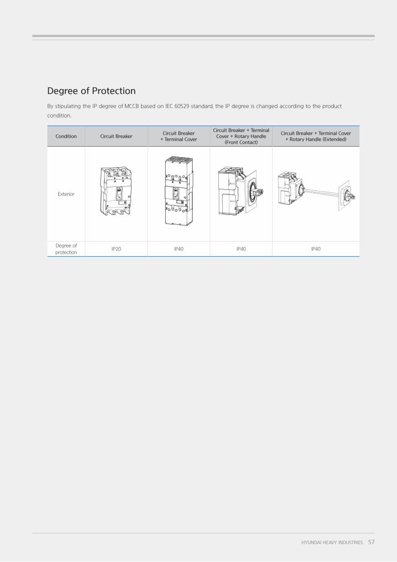
Degree of Protection
By stipulating the IP degree of MCCB based on IEC 60529 standard, the IP degree is changed according to the product
condition.
Condition Circuit BreakerCircuit Breaker
+ Terminal Cover
Circuit Breaker + Terminal Cover + Rotary Handle
(Front Contact)
Circuit Breaker + Terminal Cover + Rotary Handle (Extended)
Exterior
Degree of
protectionIP20 IP40 IP40 IP40
57HYUNDAI HEAVY INDUSTRIES
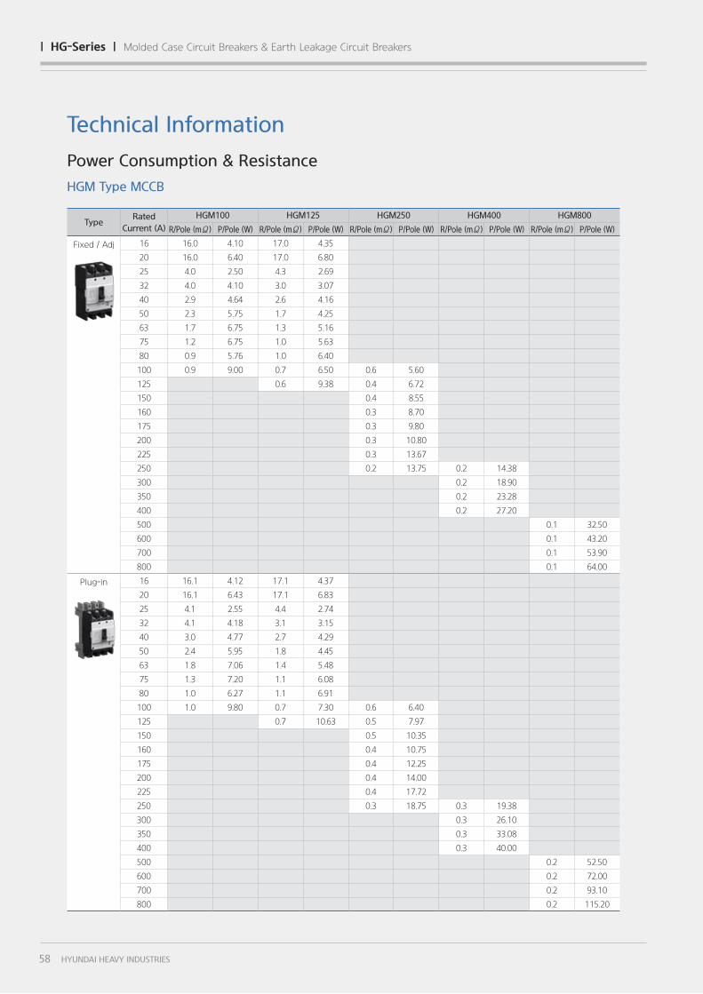
TypeRated
Current (A)
HGM100 HGM125 HGM250 HGM400 HGM800
R/Pole (mΩ) P/Pole (W) R/Pole (mΩ) P/Pole (W) R/Pole (mΩ) P/Pole (W) R/Pole (mΩ) P/Pole (W) R/Pole (mΩ) P/Pole (W)
Fixed / Adj 16 16.0 4.10 17.0 4.35
20 16.0 6.40 17.0 6.80
25 4.0 2.50 4.3 2.69
32 4.0 4.10 3.0 3.07
40 2.9 4.64 2.6 4.16
50 2.3 5.75 1.7 4.25
63 1.7 6.75 1.3 5.16
75 1.2 6.75 1.0 5.63
80 0.9 5.76 1.0 6.40
100 0.9 9.00 0.7 6.50 0.6 5.60
125 0.6 9.38 0.4 6.72
150 0.4 8.55
160 0.3 8.70
175 0.3 9.80
200 0.3 10.80
225 0.3 13.67
250 0.2 13.75 0.2 14.38
300 0.2 18.90
350 0.2 23.28
400 0.2 27.20
500 0.1 32.50
600 0.1 43.20
700 0.1 53.90
800 0.1 64.00
Plug-in 16 16.1 4.12 17.1 4.37
20 16.1 6.43 17.1 6.83
25 4.1 2.55 4.4 2.74
32 4.1 4.18 3.1 3.15
40 3.0 4.77 2.7 4.29
50 2.4 5.95 1.8 4.45
63 1.8 7.06 1.4 5.48
75 1.3 7.20 1.1 6.08
80 1.0 6.27 1.1 6.91
100 1.0 9.80 0.7 7.30 0.6 6.40
125 0.7 10.63 0.5 7.97
150 0.5 10.35
160 0.4 10.75
175 0.4 12.25
200 0.4 14.00
225 0.4 17.72
250 0.3 18.75 0.3 19.38
300 0.3 26.10
350 0.3 33.08
400 0.3 40.00
500 0.2 52.50
600 0.2 72.00
700 0.2 93.10
800 0.2 115.20
Technical Information
Power Consumption & Resistance
HGM Type MCCB
58 HYUNDAI HEAVY INDUSTRIES
| hg-Series | Molded Case Circuit Breakers & Earth Leakage Circuit Breakers
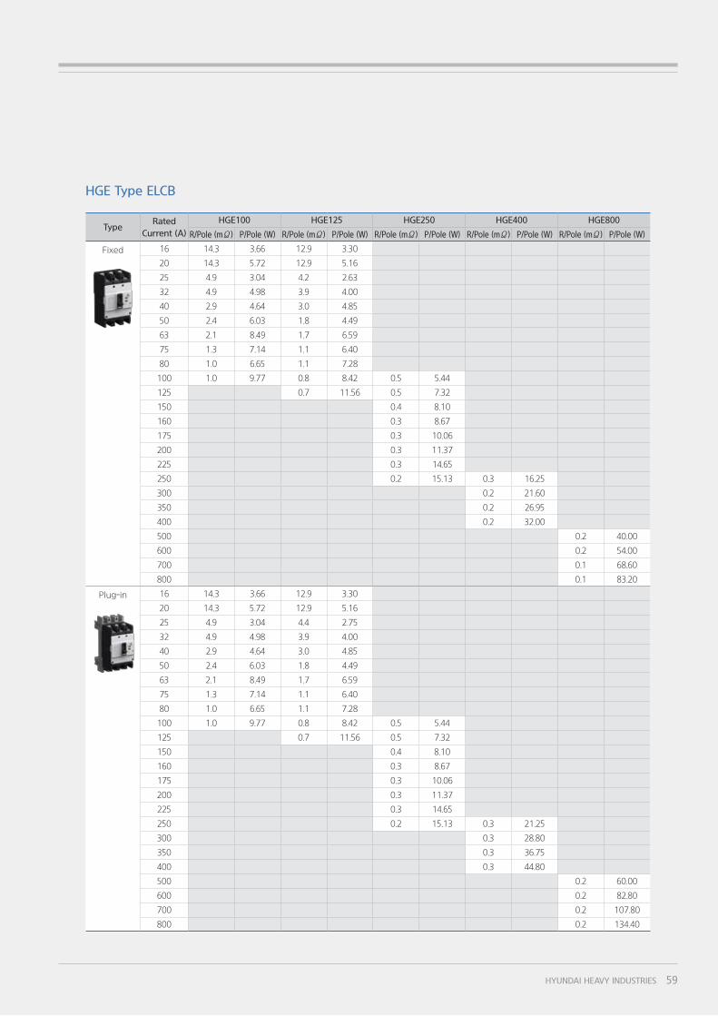
TypeRated
Current (A)
HGE100 HGE125 HGE250 HGE400 HGE800
R/Pole (mΩ) P/Pole (W) R/Pole (mΩ) P/Pole (W) R/Pole (mΩ) P/Pole (W) R/Pole (mΩ) P/Pole (W) R/Pole (mΩ) P/Pole (W)
Fixed 16 14.3 3.66 12.9 3.30
20 14.3 5.72 12.9 5.16
25 4.9 3.04 4.2 2.63
32 4.9 4.98 3.9 4.00
40 2.9 4.64 3.0 4.85
50 2.4 6.03 1.8 4.49
63 2.1 8.49 1.7 6.59
75 1.3 7.14 1.1 6.40
80 1.0 6.65 1.1 7.28
100 1.0 9.77 0.8 8.42 0.5 5.44
125 0.7 11.56 0.5 7.32
150 0.4 8.10
160 0.3 8.67
175 0.3 10.06
200 0.3 11.37
225 0.3 14.65
250 0.2 15.13 0.3 16.25
300 0.2 21.60
350 0.2 26.95
400 0.2 32.00
500 0.2 40.00
600 0.2 54.00
700 0.1 68.60
800 0.1 83.20
Plug-in 16 14.3 3.66 12.9 3.30
20 14.3 5.72 12.9 5.16
25 4.9 3.04 4.4 2.75
32 4.9 4.98 3.9 4.00
40 2.9 4.64 3.0 4.85
50 2.4 6.03 1.8 4.49
63 2.1 8.49 1.7 6.59
75 1.3 7.14 1.1 6.40
80 1.0 6.65 1.1 7.28
100 1.0 9.77 0.8 8.42 0.5 5.44
125 0.7 11.56 0.5 7.32
150 0.4 8.10
160 0.3 8.67
175 0.3 10.06
200 0.3 11.37
225 0.3 14.65
250 0.2 15.13 0.3 21.25
300 0.3 28.80
350 0.3 36.75
400 0.3 44.80
500 0.2 60.00
600 0.2 82.80
700 0.2 107.80
800 0.2 134.40
HGE Type ELCB
59HYUNDAI HEAVY INDUSTRIES
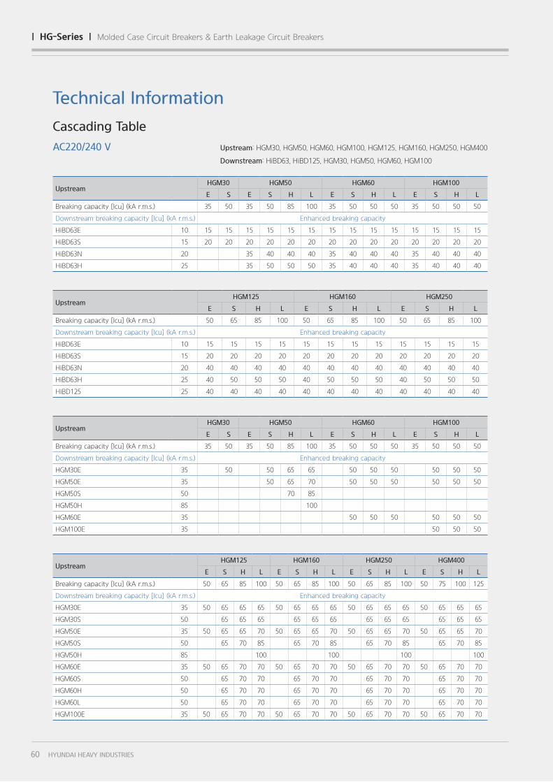
UpstreamHGM30 HGM50 HGM60 HGM100
E S E S H L E S H L E S H L
Breaking capacity [Icu] (kA r.m.s.) 35 50 35 50 85 100 35 50 50 50 35 50 50 50
Downstream breaking capacity [Icu] (kA r.m.s.) Enhanced breaking capacity
HiBD63E 10 15 15 15 15 15 15 15 15 15 15 15 15 15 15
HiBD63S 15 20 20 20 20 20 20 20 20 20 20 20 20 20 20
HiBD63N 20 35 40 40 40 35 40 40 40 35 40 40 40
HiBD63H 25 35 50 50 50 35 40 40 40 35 40 40 40
UpstreamHGM30 HGM50 HGM60 HGM100
E S E S H L E S H L E S H L
Breaking capacity [Icu] (kA r.m.s.) 35 50 35 50 85 100 35 50 50 50 35 50 50 50
Downstream breaking capacity [Icu] (kA r.m.s.) Enhanced breaking capacity
HGM30E 35 50 50 65 65 50 50 50 50 50 50
HGM50E 35 50 65 70 50 50 50 50 50 50
HGM50S 50 70 85
HGM50H 85 100
HGM60E 35 50 50 50 50 50 50
HGM100E 35 50 50 50
UpstreamHGM125 HGM160 HGM250 HGM400
E S H L E S H L E S H L E S H L
Breaking capacity [Icu] (kA r.m.s.) 50 65 85 100 50 65 85 100 50 65 85 100 50 75 100 125
Downstream breaking capacity [Icu] (kA r.m.s.) Enhanced breaking capacity
HGM30E 35 50 65 65 65 50 65 65 65 50 65 65 65 50 65 65 65
HGM30S 50 65 65 65 65 65 65 65 65 65 65 65 65
HGM50E 35 50 65 65 70 50 65 65 70 50 65 65 70 50 65 65 70
HGM50S 50 65 70 85 65 70 85 65 70 85 65 70 85
HGM50H 85 100 100 100 100
HGM60E 35 50 65 70 70 50 65 70 70 50 65 70 70 50 65 70 70
HGM60S 50 65 70 70 65 70 70 65 70 70 65 70 70
HGM60H 50 65 70 70 65 70 70 65 70 70 65 70 70
HGM60L 50 65 70 70 65 70 70 65 70 70 65 70 70
HGM100E 35 50 65 70 70 50 65 70 70 50 65 70 70 50 65 70 70
UpstreamHGM125 HGM160 HGM250
E S H L E S H L E S H L
Breaking capacity [Icu] (kA r.m.s.) 50 65 85 100 50 65 85 100 50 65 85 100
Downstream breaking capacity [Icu] (kA r.m.s.) Enhanced breaking capacity
HiBD63E 10 15 15 15 15 15 15 15 15 15 15 15 15
HiBD63S 15 20 20 20 20 20 20 20 20 20 20 20 20
HiBD63N 20 40 40 40 40 40 40 40 40 40 40 40 40
HiBD63H 25 40 50 50 50 40 50 50 50 40 50 50 50
HiBD125 25 40 40 40 40 40 40 40 40 40 40 40 40
Technical Information
Cascading Table
AC220/240 V Upstream: HGM30, HGM50, HGM60, HGM100, HGM125, HGM160, HGM250, HGM400
Downstream: HiBD63, HiBD125, HGM30, HGM50, HGM60, HGM100
60 HYUNDAI HEAVY INDUSTRIES
| hg-Series | Molded Case Circuit Breakers & Earth Leakage Circuit Breakers
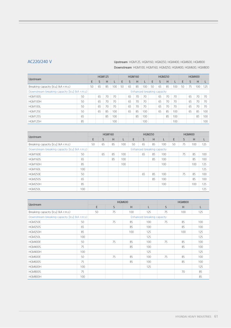
UpstreamHGM600 HGM800
E S H L S H L
Breaking capacity [Icu] (kA r.m.s.) 50 75 100 125 75 100 125
Downstream breaking capacity [Icu] (kA r.m.s.) Enhanced breaking capacity
HGM250E 50 75 85 100 75 85 100
HGM250S 65 85 100 85 100
HGM250H 85 100 125 100 125
HGM250L 100 125 125
HGM400E 50 75 85 100 75 85 100
HGM400S 75 85 100 85 100
HGM400H 100 125 125
HGM600E 50 75 85 100 75 85 100
HGM600S 75 85 100 85 100
HGM600H 100 125 125
HGM800S 75 70 85
HGM800H 100 85
UpstreamHGM125 HGM160 HGM250 HGM400
E S H L E S H L E S H L E S H L
Breaking capacity [Icu] (kA r.m.s.) 50 65 85 100 50 65 85 100 50 65 85 100 50 75 100 125
Downstream breaking capacity [Icu] (kA r.m.s.) Enhanced breaking capacity
HGM100S 50 65 70 70 65 70 70 65 70 70 65 70 70
HGM100H 50 65 70 70 65 70 70 65 70 70 65 70 70
HGM100L 50 65 70 70 65 70 70 65 70 70 65 70 70
HGM125E 50 65 85 100 65 85 100 65 85 100 65 85 100
HGM125S 65 85 100 85 100 85 100 85 100
HGM125H 85 100 100 100 100
UpstreamHGM160 HGM250 HGM400
E S H L E S H L E S H L
Breaking capacity [Icu] (kA r.m.s.) 50 65 85 100 50 65 85 100 50 75 100 125
Downstream breaking capacity [Icu] (kA r.m.s.) Enhanced breaking capacity
HGM160E 50 65 85 100 65 85 100 75 85 100
HGM160S 65 85 100 85 100 85 100
HGM160H 85 100 100 100 125
HGM160L 100 125
HGM250E 50 65 85 100 75 85 100
HGM250S 65 85 100 85 100
HGM250H 85 100 100 125
HGM250L 100 125
Upstream: HGM125, HGM160, HGM250, HGM400, HGM600, HGM800
Downstream: HGM100, HGM160, HGM250, HGM400, HGM600, HGM800
AC220/240 V
61HYUNDAI HEAVY INDUSTRIES
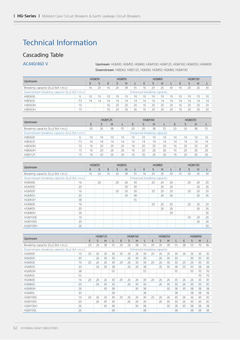
UpstreamHGM30 HGM50 HGM60 HGM100
E S E S H L E S H L E S H L
Breaking capacity [Icu] (kA r.m.s.) 16 20 16 20 38 55 16 20 26 30 16 20 26 30
Downstream breaking capacity [Icu] (kA r.m.s.) Enhanced breaking capacity
HiBD63E 6 10 10 10 10 10 10 10 10 10 10 10 10 10 10
HiBD63S 7.5 14 14 14 14 14 14 14 14 14 14 14 14 14 14
HiBD63N 10 16 20 20 20 16 20 20 20 16 20 20 20
HiBD63H 15 16 20 26 26 16 20 20 20 16 20 20 20
UpstreamHGM30 HGM50 HGM60 HGM100
E S E S H L E S H L E S H L
Breaking capacity [Icu] (kA r.m.s.) 16 20 16 20 38 55 16 20 26 30 16 20 26 30
Downstream breaking capacity [Icu] (kA r.m.s.) Enhanced breaking capacity
HGM30E 16 20 20 26 30 20 20 20 20 20 20
HGM30S 20 30 30 26 26 26 26
HGM50E 16 20 26 30 20 20 20 20 20 20
HGM50S 20 30 38 26 26 26 26
HGM50H 38 55
HGM60E 16 20 20 20 20 20 20
HGM60S 20 26 26 26 26
HGM60H 26 30 30
HGM100E 16 20 20 20
HGM100S 20 26 26
HGM100H 26 30
UpstreamHGM125 HGM160 HGM250 HGM400
E S H L E S H L E S H L E S H L
Breaking capacity [Icu] (kA r.m.s.) 20 26 38 55 20 26 38 55 20 26 38 55 38 50 70 85
Downstream breaking capacity [Icu] (kA r.m.s.) Enhanced breaking capacity
HGM30E 16 20 26 26 30 20 26 26 30 20 26 26 30 26 26 30 30
HGM30S 20 26 30 30 26 30 30 26 30 30 30 30 30
HGM50E 16 20 26 26 30 20 26 30 30 20 26 30 30 20 26 30 30
HGM50S 20 26 30 38 26 30 38 26 30 38 20 30 38 38
HGM50H 38 55 55 55 50 70 70
HGM50L 55 70 70
HGM60E 16 20 26 26 30 20 26 26 30 20 26 26 30 26 26 30 30
HGM60S 20 26 30 30 26 30 30 26 30 30 26 30 30 30
HGM60H 26 30 38 30 38 30 38 30 38 38 38
HGM60L 30 38 38 38 38 38 38
HGM100E 16 20 26 26 30 20 26 26 30 20 26 26 30 26 26 30 30
HGM100S 20 26 30 30 26 30 30 26 30 30 26 30 30 30
HGM100H 26 30 38 30 38 30 38 30 38 38 38
HGM100L 26 38 38 38 38 38 38
UpstreamHGM125 HGM160 HGM250
E S H L E S H L E S H L
Breaking capacity [Icu] (kA r.m.s.) 20 26 38 55 20 26 38 55 20 26 38 55
Downstream breaking capacity [Icu] (kA r.m.s.) Enhanced breaking capacity
HiBD63E 6 10 10 10 10 10 10 10 10 10 10 10 10
HiBD63S 7.5 14 14 14 14 14 14 14 14 14 14 14 14
HiBD63N 10 16 20 20 20 16 20 20 20 16 20 20 20
HiBD63H 15 16 20 26 26 16 20 26 26 16 20 26 26
HiBD125 15 16 20 26 26 16 20 26 26 16 20 26 26
Cascading Table
AC440/460 V Upstream: HGM30, HGM50, HGM60, HGM100, HGM125, HGM160, HGM250, HGM400
Downstream: HiBD63, HiBD125, HGM30, HGM50, HGM60, HGM100
Technical Information
62 HYUNDAI HEAVY INDUSTRIES
| hg-Series | Molded Case Circuit Breakers & Earth Leakage Circuit Breakers
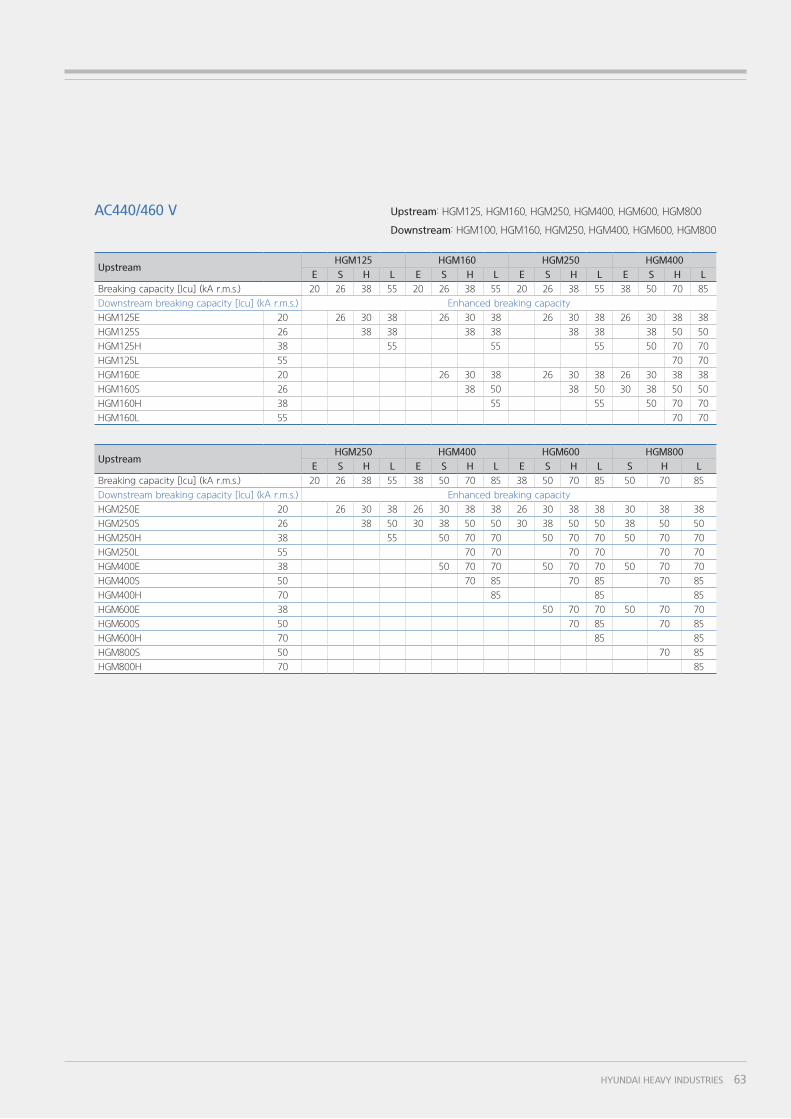
UpstreamHGM125 HGM160 HGM250 HGM400
E S H L E S H L E S H L E S H L
Breaking capacity [Icu] (kA r.m.s.) 20 26 38 55 20 26 38 55 20 26 38 55 38 50 70 85
Downstream breaking capacity [Icu] (kA r.m.s.) Enhanced breaking capacity
HGM125E 20 26 30 38 26 30 38 26 30 38 26 30 38 38
HGM125S 26 38 38 38 38 38 38 38 50 50
HGM125H 38 55 55 55 50 70 70
HGM125L 55 70 70
HGM160E 20 26 30 38 26 30 38 26 30 38 38
HGM160S 26 38 50 38 50 30 38 50 50
HGM160H 38 55 55 50 70 70
HGM160L 55 70 70
UpstreamHGM250 HGM400 HGM600 HGM800
E S H L E S H L E S H L S H L
Breaking capacity [Icu] (kA r.m.s.) 20 26 38 55 38 50 70 85 38 50 70 85 50 70 85
Downstream breaking capacity [Icu] (kA r.m.s.) Enhanced breaking capacity
HGM250E 20 26 30 38 26 30 38 38 26 30 38 38 30 38 38
HGM250S 26 38 50 30 38 50 50 30 38 50 50 38 50 50
HGM250H 38 55 50 70 70 50 70 70 50 70 70
HGM250L 55 70 70 70 70 70 70
HGM400E 38 50 70 70 50 70 70 50 70 70
HGM400S 50 70 85 70 85 70 85
HGM400H 70 85 85 85
HGM600E 38 50 70 70 50 70 70
HGM600S 50 70 85 70 85
HGM600H 70 85 85
HGM800S 50 70 85
HGM800H 70 85
AC440/460 V Upstream: HGM125, HGM160, HGM250, HGM400, HGM600, HGM800
Downstream: HGM100, HGM160, HGM250, HGM400, HGM600, HGM800
63HYUNDAI HEAVY INDUSTRIES
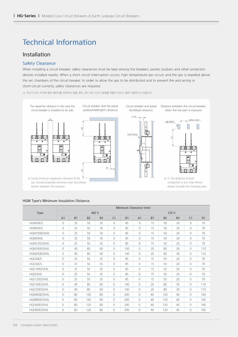
Type
Minimum Clearance (mm)
460 V 220 V
A1 B1 B2 B3 C1 D1 A1 B1 B2 B3 C1 D1
HGM30E/S 0 25 50 35 0 85 0 15 50 20 0 70
HGM50E/S 0 25 50 35 0 85 0 15 50 20 0 70
HGM100E/S/H/L 0 25 50 35 0 85 0 15 50 20 0 70
HGM50H/L 0 25 50 35 0 85 0 15 50 20 0 70
HGM125E/S/H/L 0 25 50 35 0 85 0 15 50 20 0 70
HGM160E/S/H/L 0 40 80 60 0 140 0 20 80 30 0 110
HGM250E/S/H/L 0 40 80 60 0 140 0 20 80 30 0 110
HGE30E/S 0 25 50 35 0 85 0 15 50 20 0 70
HGE50E/S 0 25 50 35 0 85 0 15 50 20 0 70
HGE100E/S/H/L 0 25 50 35 0 85 0 15 50 20 0 70
HGE50H/L 0 25 50 35 0 85 0 15 50 20 0 70
HGE125E/S/H/L 0 25 50 35 0 85 0 15 50 20 0 70
HGE160E/S/H/L 0 40 80 60 0 140 0 20 80 30 0 110
HGE250E/S/H/L 0 40 80 60 0 140 0 20 80 30 0 110
HGM400E/S/H/L 0 80 120 80 0 200 0 40 120 40 0 160
HGM800E/S/H/L 0 80 120 80 0 200 0 40 120 40 0 160
HGE400E/S/H/L 0 80 120 80 0 200 0 40 120 40 0 160
HGE800E/S/H/L 0 80 120 80 0 200 0 40 120 40 0 160
HGM Type's Minimum Insulation Distance.
Technical Information
Installation
Safety Clearance
When installing a circuit breaker, safety clearances must be kept among the breakers, panels, busbars and other protection
devices installed nearby. When a short circuit interruption occurs, high temperature gas occurs and the gas is expelled above
the arc chambers of the circuit breaker. In order to allow the gas to be distributed and to prevent fire and arcing or
short-circuit currents, safety clearances are required.
B1
Front Panel
B2
B3
A1
C1=0
60mm Over노출 충전부
D1
※ Using minimum separation distance (A=0),
you should assemble terminal cover and phase
barrier between the product.
The separtion distance in the case the
circuit breaker is installed sis by side.
Circuit breaker and the panel
up/down/left/right's distance.
Circuit breaker and panel
front/back distance.
Distance between the circuit breaker
when the live part is exposed
※ 차단기 단자 사이에 절연 베리어를 취부하지 않을 경우, 2차 단락 사고가 발생할 위험이 있으니 필히 사용하시기 바랍니다.
※ If the distance of both
conductors is less than 60mm,
please insulate the charging part.
64 HYUNDAI HEAVY INDUSTRIES
| hg-Series | Molded Case Circuit Breakers & Earth Leakage Circuit Breakers
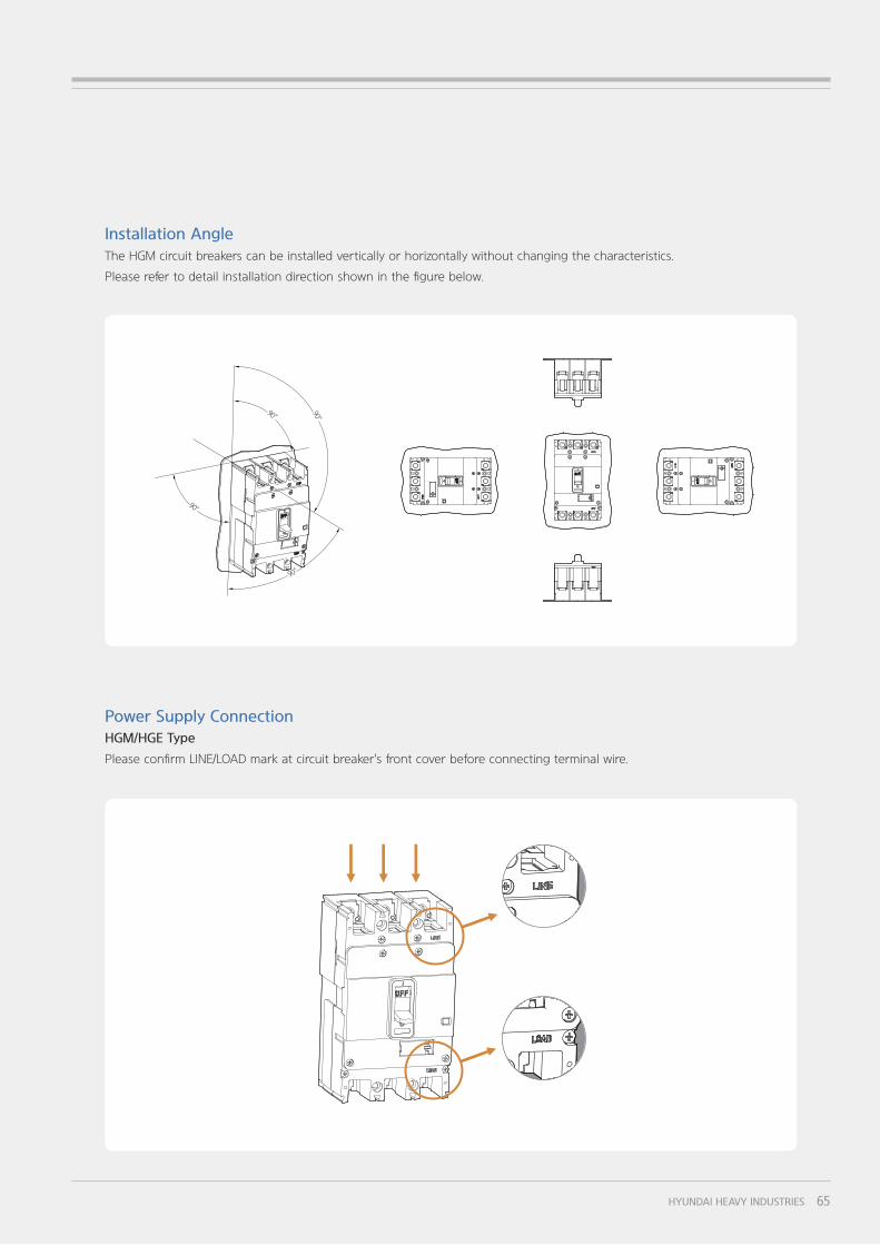
Installation Angle
The HGM circuit breakers can be installed vertically or horizontally without changing the characteristics.
Please refer to detail installation direction shown in the figure below.
Power Supply Connection
HGM/HGE Type
Please confirm LINE/LOAD mark at circuit breaker's front cover before connecting terminal wire.
90°
90°
90°
90°
65HYUNDAI HEAVY INDUSTRIES
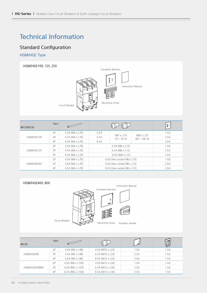
HGM/HGE100, 125, 250
Part
MCCB
HGM/HGE400
2P 4 EA (M5 x L98) 4 EA (M10 x L23) 1 EA 1 EA
3P 4 EA (M5 x L98) 6 EA (M10 x L23) 2 EA 1 EA
4P 6 EA (M5 x L98) 8 EA (M10 x L23) 3 EA 1 EA
HGM/HGE630/800
2P 4 EA (M6 x L103) 4 EA (M12 x L30) 1 EA 1 EA
3P 4 EA (M6 x L103) 6 EA (M12 x L30) 2 EA 1 EA
4P 6 EA (M6 x L103) 8 EA (M12 x L30) 3 EA 1 EA
Technical Information
Standard Configuration
HGM/HGE Type
Circuit BreakerAuxiliary Handle
HGM/HGE400, 800
Part
MCCB/ELCB
HGM/HGE100
2P 2 EA (M4 x L70) 4 EA(M5 x L15)
(15 - 50 A)
(M8 x L15)
(60 - 100 A)
1 EA
3P 4 EA (M4 x L70) 6 EA 2 EA
4P 6 EA (M4 x L70) 8 EA 3 EA
HGM/HGE125
2P 2 EA (M4 x L70) 4 EA (M8 x L15) 1 EA
3P 4 EA (M4 x L70) 6 EA (M8 x L15) 2 EA
4P 6 EA (M4 x L70) 8 EA (M8 x L15) 3 EA
HGM/HGE250
2P 4 EA (M4 x L70) 4 EA (Hex socket M8 x L15) 1 EA
3P 4 EA (M4 x L70) 6 EA (Hex socket M8 x L15) 2 EA
4P 6 EA (M4 x L70) 8 EA (Hex socket M8 x L15) 3 EA
Circuit Breaker
Insulation Barriers
Insulation Barriers
. Instruction Manual
Instruction Manual
Mounting Screw
Mounting Screw
66 HYUNDAI HEAVY INDUSTRIES
| hg-Series | Molded Case Circuit Breakers & Earth Leakage Circuit Breakers
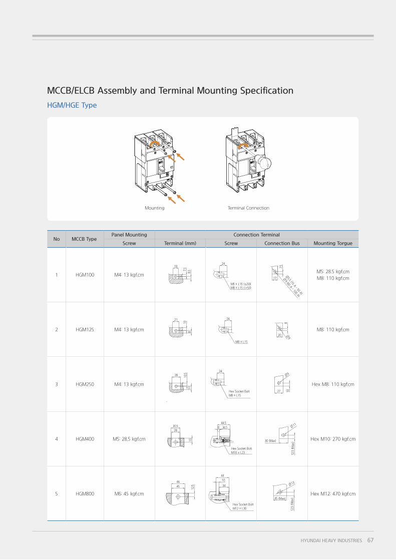
No MCCB TypePanel Mounting Connection Terminal
Screw Terminal (mm) Screw Connection Bus Mounting Torgue
1 HGM100 M4: 13 kgf.cmM5: 28.5 kgf.cm
M8: 110 kgf.cm
2 HGM125 M4: 13 kgf.cm M8: 110 kgf.cm
3 HGM250 M4: 13 kgf.cm Hex M8: 110 kgf.cm
4 HGM400 M5: 28.5 kgf.cm Hex M10: 270 kgf.cm
5 HGM800 M6: 45 kgf.cm Hex M12: 470 kgf.cm
24 18
Ø5.5 (15 A - 50 A)
Ø9 (60 A - 100 A)
M5 x L15 (≦50)M8 x L15 (>50)
17
7.5
7.5
8.5
100AF
Specification of Mounting Screw: M4 x L70 P/W
Specification of Terminal Screw: (Less than 50 A) M5 x L15 P/W P/W
(Excess than 50 A) M8 x L15 S/W P/W
24 18
Ø5.5 (15 A - 50 A)
Ø9 (60 A - 100 A)
M5 x L15 (≦50)M8 x L15 (>50)
17
7.5
7.5
8.5
100AF
Specification of Mounting Screw: M4 x L70 P/W
Specification of Terminal Screw: (Less than 50 A) M5 x L15 P/W P/W
(Excess than 50 A) M8 x L15 S/W P/W
24 18
Ø5.5 (15 A - 50 A)
Ø9 (60 A - 100 A)
M5 x L15 (≦50)M8 x L15 (>50)
177.5
7.5
8.5
100AF
Specification of Mounting Screw: M4 x L70 P/W
Specification of Terminal Screw: (Less than 50 A) M5 x L15 P/W P/W
(Excess than 50 A) M8 x L15 S/W P/W
Ø9
125AF
Specification of Mounting Screw: M4 x L70 P/W
Specification of Terminal Screw: M8 x L15 S/W P/W
24 21
M8 x L15
20
810
8
250AF
Specification of Mounting Screw: M4 x L70 P/W
Specification of Terminal Screw: Hex Socket Bolt M8 x L15 S/W P/W
27 10
Ø924 28
Hex Socket BoltM8 x L15
10.5
11
Hex Socket BoltM10 x L23
44.5
8 36.5 Ø11
30 (Max)
12.5 (Max)
28
30.5
13
10
34
44
Hex Socket BoltM12 x L30
46
45
12.5
Ø13
45 (Max)
12.5 (Max)
10
34
44
Hex Socket BoltM12 x L30
46
45
12.5
Ø13
45 (Max)
12.5 (Max)
10
34
44
Hex Socket BoltM12 x L30
46
45
12.5
Ø13
45 (Max)
12.5 (Max)
Hex Socket BoltM10 x L23
44.5
8 36.5 Ø11
30 (Max)
12.5 (Max)
28
30.5
13
Hex Socket BoltM10 x L23
44.5
8 36.5 Ø11
30 (Max)
12.5 (Max)
28
30.5
13
250AF
Specification of Mounting Screw: M4 x L70 P/W
Specification of Terminal Screw: Hex Socket Bolt M8 x L15 S/W P/W
27 10
Ø924 28
Hex Socket BoltM8 x L15
10.5
11
250AF
Specification of Mounting Screw: M4 x L70 P/W
Specification of Terminal Screw: Hex Socket Bolt M8 x L15 S/W P/W
27 10
Ø924 28
Hex Socket BoltM8 x L15
10.5
11
Ø9
125AF
Specification of Mounting Screw: M4 x L70 P/W
Specification of Terminal Screw: M8 x L15 S/W P/W
24 21
M8 x L15
20
810
8
Ø9
125AF
Specification of Mounting Screw: M4 x L70 P/W
Specification of Terminal Screw: M8 x L15 S/W P/W
24 21
M8 x L15
20
810
8
MCCB/ELCB Assembly and Terminal Mounting Specification
HGM/HGE Type
Mounting Terminal Connection
67HYUNDAI HEAVY INDUSTRIES


![Open Archive TOULOUSE Archive Ouverte (OATAO) · The “Space Product Assurance - Derating - EEE components” ECSS-Q- ST-30-11C [14] specifies electrical derating requirements applicable](https://img.pdfslide.us/doc/110x75/5b9509e309d3f2205c8c0df8/open-archive-toulouse-archive-ouverte-oatao-the-space-product-assurance.jpg)