Embed Size (px)
Citation preview

In the UNITED STATES call us toll free1 - 888 - 818 HORN
TECHNICAL INFORMATION
It is simple and easy to calculate your speed and feeds using HORN‘S HCT program. We recommend that you calculate the cutting data with this program as it will provide you with the best cutting performance and results. Basic features of the calculations can be found on the follwing pages.
Select the shortest possible clamping device and milling shank, and control the runout tolerance of the tools.Large cutting widths in combination with long overhangs require specific manufacturing methods such as dividing the cutting width to achieve the best possible cutting result due to reduced cutting forces.
When using a large diameter cutter, whose relationship is close to the bore diameter, manufacturing cycletime can be reduced, due to the smaller center of rotation and higher feed rates. Many times the rotation of the milling cutter centre will be defined by the parameters of the workpiece and the whole application setup.
We recommend to use a torque screw driver to achieve the indicated torque values per insert and tool type. Additional additives such as copper paste are not permitted. This will have a negative effect and change the clamping forces.All clamping screws are already coated with additives.
HCT (HORN Circular Technology)- safe and fast -Your cutting data for groove milling by circular interpolation of internal and external grooves as well as groove milling of linear grooves.System requirements from Windows 95. Available on CD-ROM.
Feed rates and time calculation
Overhang of the milling cutter
Diameter of the milling cutter
Clamping torque of the screwsMd
BASIC RECOMMENDATIONS
H1
H

In the UNITED STATES call us toll free1 - 888 - 818 HORN
Ramp angle > 45°
TECHNICAL INFORMATION
Most HORN milling tools are right handed , and it is recommended to use them with the climb milling process as this is generally recommend for carbide tools.
Milling direction
A simple radial entry of the milling cutter creates a very long contact angle which leads to vibrations which will not disappear for the rest of the milling operation and are visual on the bottom of the groove.It is recommended to enter the groove with a ramp angle of 45° up to 180° to the maximum depth of cut. The calculated cutting data refers to the milling condition when the insert is in the full cut but can be also used for the entry loop.
Milling entry into the workpiece
HORN milling inserts are manufactured with a round chip breaker. This means that beyond a depth of cut of 2 mm in axial direction the insert gets a negative cutting angle. Milling inserts are limited to a depth of cut of 2 mm when used for helical interpolation. Larger depths of cut can only be produced when choosing special chip breakers. Please contact us in case of any further questions.
Bore milling and offset milling by helical interpolation
H2
H

In the UNITED STATES call us toll free1 - 888 - 818 HORN
TECHNICAL INFORMATION
When entering through a bore off center and without rotating it is possible to generate back chamfers and flats with inserts having a larger cutting diameter than the bore diameter. Single edged cutters have no run out tolerance.
Sinlge edged inserts
With HORN thread milling inserts the thread profile is generated in one full cut to the profile depth of the thread. This produces threads with minimal taper especially in high alloyed steels.In blind holes it is recommended to mill from the bottom to the top. Otherwise there is the risk of damaging the tool because of milling into chips at the bottom of the blind hole.
A general recommendation for thread milling:The milling cutter diameter should not exceed 70% of the minor diameter of the thread. Otherwise recutting of the profile occurs which could bring the whole thread out of tolerance.
Thread milling
H3
H
In the UNITED STATES call us toll free1 - 888 - 818 HORN
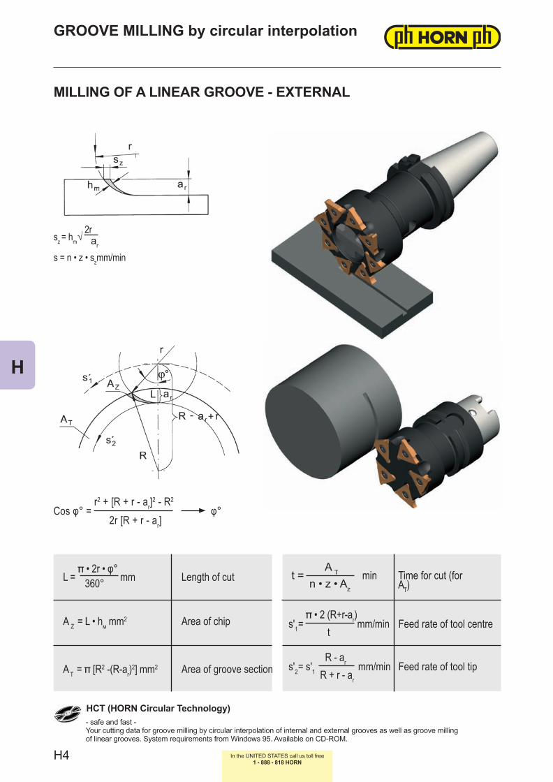
MILLING OF A LINEAR GROOVE - EXTERNAL
HCT (HORN Circular Technology)
AT = [R2 -(R-ar)2] mm2
L = • 2r • φ°
mm360°t =
A T
n • z • Az
min
A Z = L • hм mm2
s'2= s'1R - ar mm/min
R + r - ar
s'1= • 2 (R+r-ar)mm/min
tArea of chip
Length of cut
Area of groove section
Time for cut (for AT)
sz = hm√ 2r
ar
s = n • z • szmm/min
Cos φ° = r2 + [R + r - ar]2 - R2
φ°2r [R + r - ar]
GROOVE MILLING by circular interpolation
- safe and fast -Your cutting data for groove milling by circular interpolation of internal and external grooves as well as groove milling of linear grooves. System requirements from Windows 95. Available on CD-ROM.
Feed rate of tool centre
Feed rate of tool tip
H4
H
In the UNITED STATES call us toll free1 - 888 - 818 HORN
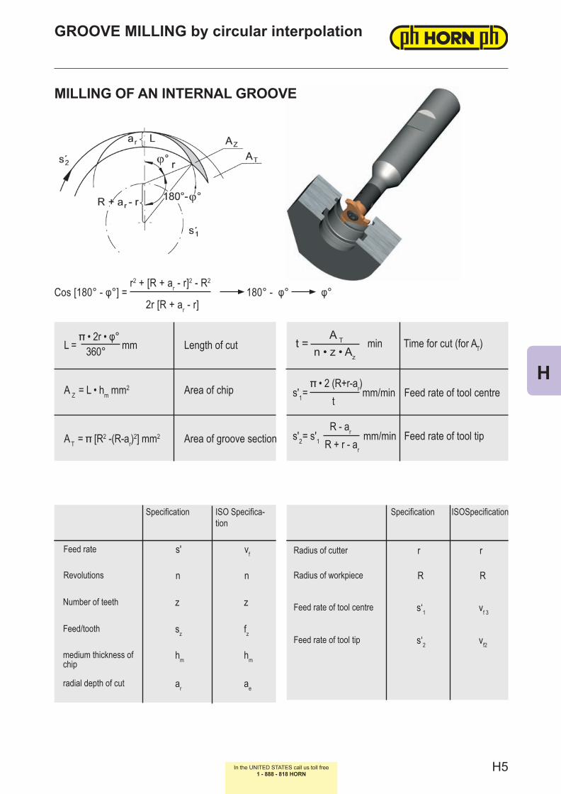
Cos [180° - φ°] = r2 + [R + ar - r]2 - R2
180° - φ° φ°2r [R + ar - r]
Feed rate
Specification
MILLING OF AN INTERNAL GROOVE
GROOVE MILLING by circular interpolation
Revolutions
Feed/tooth
Number of teeth
medium thickness of chip
radial depth of cut
ISO Specifica-tion
Specification ISOSpecification
Feed rate of tool centre
Feed rate of tool tip
Radius of cutter
Radius of workpiece
AT = [R2 -(R-ar)2] mm2
L = • 2r • φ°
mm360°t =
A T
n • z • Az
min
A Z = L • hm mm2
s'2= s'1R - ar mm/min
R + r - ar
s'1= • 2 (R+r-ar)mm/min
tArea of chip
Length of cut
Area of groove section
Time for cut (for AT)
Feed rate of tool centre
Feed rate of tool tip
s' vf
n n
sz fz
z z
hm hm
ar ae
r r
R R
s‘1 vf 3
s‘2 vf2
H5
H

Type Screw Md Nm Torquelbf-in.
Wrench Blade
380 5.12T20P 6.0 - 6.5 53 - 58 T20PQ DT20PK / DT20PQ
381.0... 5.12T20P 6.0 - 6.5 53 - 58 T20PQ DT20PK / DT20PQ
382...06 5F.06T15P 5.0 - 5.5 44 - 49 T15PQ DT15PK
382...08 5F.08T20P 5.0 - 5.5 44 - 49 T20PQ DT20PK
382...10/12/14 5.10T20P 6.0 - 6.5 53 - 58 T20PQ DT20PK / DT20PQ
383...06 5F.06T15P 5.0 - 5.5 44 - 49 T15PQ DT15PK
383...08 5F.08T20P 5.0 - 5.5 44 - 49 T20PQ DT20PK
383...10/12 5.10T20P 6.0 - 6.5 53 - 58 T20PQ DT20PK / DT20PQ
ABS 5.12T20P 6.0 - 6.5 53 - 58 T20PQ DT20PK / DT20PQ
ADR.01... C009000 0.75 7 T6W DT6K
ADR.02/03... C009001 1.5 13 T8L DT8K
ADR.04/05/06... C009002 1.5 13 T8L DT8K
B105/BKT105 6.075T15P 5.0 44 T15PQ DT15PK
B110/BKT110 6.075T15P 5.0 44 T15PQ DT15PK
BKT356 5.12T20P 6.0 - 6.5 53 - 58 T20PQ DT20PK / DT20PQ
DAHM 030.3070.T10P 3.0 27 T10PL DT10PK
DAM31...02B 030.2541.T8P 1.3 12 T8PL DT8PK
DAM31...03A/B 030.2547.T8P 1.3 12 T8PL DT8PK
DAM31...04A/B 030.2553.T8P 1.3 12 T8PL DT8PK
DAM31...05A/B 030.2557.T8P 1.3 12 T8PL DT8PK
DAM32...02A/B 030.3562.T10P 3.5 31 T10PL DT10PK
DAM32.025.D...03A/B 030.3569.T10P 3.5 31 T10PL DT10PK
DAM32.032.D...03A/B 030.3576.T10P 3.5 31 T10PL DT10PK
DAM32.417.M...03B 030.3569.T10P 3.5 31 T10PL DT10PK
DRHD 6.075T15P 5.0 44 T15PQ DT15PK
HSK 5.12T20P 6.0 - 6.5 53 - 58 T20PQ DT20PK / DT20PQ
L381.A... 5F.08T20P 5.0 - 5.5 44 - 49 T20PQ DT20PK
L381.D080... 5F.08T20P 5.0 - 5.5 44 - 49 T20PQ DT20PK
L381.D086... 5.12T20P 6.0 - 6.5 53 - 58 T20PQ DT20PK / DT20PQ
L381.G070... 5.10T20P 6.0 - 6.5 53 - 58 T20PQ DT20PK / DT20PQ
L381.G080... 5F.08T20P 5.0 - 5.5 44 - 49 T20PQ DT20PK
L381.G086/090/098 5.12T20P 6.0 - 6.5 53 - 58 T20PQ DT20PK / DT20PQ
L381.G090... 5.12T20P 6.0 - 6.5 53 - 58 T20PQ DT20PK / DT20PQ
L381.N090... 5F.08T20P 5.0 - 5.5 44 - 49 T20PQ DT20PK
L381.S... 5.15T20P 6.0 - 6.5 53 - 58 T20PQ DT20PK / DT20PQ
L381.T... 5F.08T20P 5.0 - 5.5 44 - 49 T20PQ DT20PK
L381.X090... 5.12T20P 6.0 - 6.5 53 - 58 T20PQ DT20PK / DT20PQ
LM275.D... 030.357P.315 2.5 - 3.0 22 - 27 T10PL DT10PK
In the UNITED STATES call us toll free1 - 888 - 818 HORN
TORQUE OF SCREWS
Following torques are allowed for screws of inserts.For torque screw drivers please see chapter additional equipment.
H6
H

Type Screw Md Nm Torquelbf-in.
Wrench Blade
M116 5.13T20EP 6.0 - 6.5 53 - 58 T20PQ DT20PK / DT20PQ
M117K...05 030.265P.0821 1.2 11 T8PL DT8PK
M117K...07 030.265P.0819 1.2 11 T8PL DT8PK
M117K...09 030.400P.0227 4.3 38 T15PQ DT15PK
M117.MD10... 030.400P.0227 4.3 38 T15PQ DT15PK
M117U...05 030.265P.0818 1.2 11 T8PL DT8PK
M117U...07 2.6.5T8EP 1.2 11 T8PL DT8PK
M117P...05 030.265P.0818 1.2 11 T8PL DT8PK
M117P...07 2.6.5T8EP 1.2 11 T8PL DT8PK
M275 3.5.10T10P 2.5 - 3.0 22 - 27 T10PL DT10PK
M306 2.6.5T8EP 1.2 11 T8PL DT8PK
M308 3.5.12T10EP 3.0 27 T10PL DT10PK
M310...03 030.0324.T7P 1.2 11 T7PL DT7PK
M310...04 030.3535.T8P 2.0 18 T8PL DT8PK
M310...05 030.3543.T8P 2.0 18 T8PL DT15PK
M311 4.14T15P 5.0 44 T15PQ DT15PK
M311...00.B/E 4.16T15KP 5.0 44 T15PQ DT15PK
M313 5.14T20P 6.5 58 T20PQ DT20PK / DT20PQ
M313...00.B/E 5.15T20KP 6.5 58 T20PQ DT20PK / DT20PQ
M328 5.14T20P 6.5 58 T20PQ DT20PK / DT20PQ
M328...00.B/E 5.13T20KP 6.5 58 T20PQ DT20PK / DT20PQ
M328.0020.D... 5.17T20P 6.5 58 T20PQ DT20PK / DT20PQ
M332 5.17T20P 6.5 58 T20PQ DT20PK / DT20PQ
M335 6.17T25P 12.0 106 T25PQ DT20PQ
MDR.01... C009000 0.75 7 T6W DT6K
MDR.02/03... C009001 1.5 13 T8L DT8K
MDR.04/05/06... C009002 1.5 13 T8L DT8K
MDR.08/09/10... C009004 3.5 31 T15Q DT15K
R381.X090... 5.12T20P 6.0 - 6.5 53 - 58 T20PQ DT20PK / DT20PQ
R381.X073... 5F.08T20P 6.0 - 6.5 53 - 58 T20PQ DT20PK / DT20PQ
RM275.D... 030.357P.315 2.5 - 3.0 22 - 27 T10PL DT10PK
RM275.T... 3.510.T10P 2.5 - 3.0 22 - 27 T10PL DT10PK
SM328 5.17T20P 6.5 58 T20PQ DT20PK / DT20PQ
Z313...057 5.26T20P 6.5 58 T20PQ DT20PK / DT20PQ
Z313...082 5.28T20P 6.5 58 T20PQ DT20PK / DT20PQ
Z313...107 5.30T20P 6.5 58 T20PQ DT20PK / DT20PQ
In the UNITED STATES call us toll free1 - 888 - 818 HORN
Following torques are allowed for screws of inserts.For torque screw drivers please see chapter additional equipment.
TORQUE OF SCREWS
H7
H

Dimensions in mm Part number Inserts (inch and metric) Use Page
l1 dg6 l2 d1 Type tmax Ds130 12 40 11 M116.0012.01B
116 4.3 20.4 A59130 12 56 11 M116.0012.02B130 16 40 11 M116.0016.01B/E
116 4.3 20.4 A59130 16 56 11 M116.0016.02B/E150 16 80 11 M116.0016.03B/E
80 12 21 6 M306.0012.01B/E/A108/306 1.0/2.5 9.6/11.7 A3 - A490 12 30 6 M306.0012.02B/E/A
100 12 42 6 M306.0012.03B/E/A100 7.5 - 6 M306.0707.03A
108/306 0.85/2.0 9.3/11.7D3; E2
120 10 - 6 M306.1010.03A E290 12 30 7.3 M306.0712.02B/E/A
108/306 0.7/2.0 9.6/11.7 D3100 16 25 7.3 M306.0716.01/B/E/A
60 10 15.2 6 M306.ST10.01A 108/306 1.0/2.5 9.4/11.7 A595 12 29 8 M308.0012.01B/E/A
111/308/608 2.3/3.5 13.4/15.7 A25-A26110 12 42 8 M308.0012.02B/E/A120 12 56 8 M308.0012.03B/E/A160 12 - - M308.0012.07A 111/308/608 2.3/3.5 13.4/15.7 D11; E8110 12 42 9.5 M308.1012.02B/E/A
111/308 1.5/2.7 13.4/15.7 D11110 16 33 9.5 M308.1016.01B/E/A60 10 17.7 8 M308.ST10.01A
111/308 2.3/3.5 13.4/15.7 A2770 13 25.7 8 M308.ST13.01A
100 12 32 9 M311.0012.01B/E/A311/611 3.5/2.5 17.7 A43-A44100 12 45 9 M311.0012.02B/E/A
120 12 64 9 M311.0012.03B/E/A90 16 25 9 M311.0016.00B/E 311 3.6 17.0 G3
100 16 32 9 M311.0016.01B/E/A311/611 3.5/2.5 17.7 A43-A44110 16 45 9 M311.0016.02B/E/A
130 16 64 9 M311.0016.03B/E/A110 16 32 13 M311.1316.01B/E/A
311/611 1.5 17.7 D21130 16 45 13 M311.1316.02B/E/A145 16 64 13 M311.1316.03B/E/A
60 10 17.7 9 M311.ST10.01A311/611 A4570 13 25.7 9 M311.ST13.01A 3.5 17.7
80 16 25.7 9 M311.ST16.01A100 12 - - M313.0012.01B/E/A
313/613 4.5/3.2 21.7 A65-A66130 12 - - M313.0012.02B/E/A
93 16 30 11.5 M313.0016.00B/E 313 4.75 21.7 G7
100 16 42 12 M313.0016.01B/E/A313/613 4.5/3.2 21.7 A65-A66130 16 60 12 M313.0016.02B/E/A
160 16 85 12 M313.0016.03B/E/A160 16 20 12 M313.0016.07A
313/613 2.5 21.7 D35110 20 45 16 M313.1620.01A/B/E130 20 60 16 M313.1620.02A/B/E160 20 85 16 M313.1620.03A/B/E
In the UNITED STATES call us toll free1 - 888 - 818 HORN
Dimensions in mm
Available METRIC size carbide andtungsten alloy shanks - Summary
H8
H

Dimensions in mm Part number Inserts (inch and metric) Use Page
l1 dg6 l2 d1 Type tmax Ds60 10 10.7 11.3 M313.ST10.01A
313/613 4.85 21.7 A6770 13 25.7 11.3 M313.ST13.01A80 16 25.7 11.3 M313.ST16.01A
120 9 - - M328.0909.01A328/628 9.3 28 A95
100 12 36 9 M328.0912.01A100 16 42 14.3 M328.0016.01B/E/A
325/328/628 5.0/6.4/4.3 24.8/27.7 A93 - A94
130 16 60 14.3 M328.0016.02B/E/A160 16 85 14.3 M328.0016.03B/E/A100 20 42 14.3 M328.0020.01B/E/A130 20 60 14.3 M328.0020.02B/E/A160 20 85 14.3 M328.0020.03B/E/A
104 20 35 13.5 M328.0020.00B/E 328 6.5 27.7 G10
130 20 20 15 SM328.0020.05B/E
328
6.0
27.7 D43145 20 - - SM328.0020.06B/E 3.5160 20 20 15 SM328.0020.07B/E 6.0200 20 - - SM328.0020.08B/E 3.5
70 13 10.7 14 M328.ST13.01A328/628 6.0 27.7 A96
100 20 35.7 14 M328.ST20.01A100 16 42 16 M332.0016.01A
332 8.5 31.7 A11
130 16 60 16 M332.0016.02A160 16 85 16 M332.0016.03A100 20 42 20 M332.0020.01A130 20 60 20 M332.0020.02A160 20 85 20 M332.0020.03A100 12 32 11 M332.0012.2.01A
332 10 31.7A112
100 16 32 11 M332.0016.2.01A70 13 25 11 M332.ST13.2.01A A113
100 20 40 17.5 M335.0020.01B/A335 7.9/8.0 34.7 A127 - A128
130 20 60 17.5 M335.0020.02B/A/E
In the UNITED STATES call us toll free1 - 888 - 818 HORN
Dimensions in mm
Available METRIC size carbide andtungsten alloy shanks - Summary
H9
H

In the UNITED STATES call us toll free1 - 888 - 818 HORN
3.150 .500 .827 .236 MU306.0500.01B 108/306 .039/.098 .378/.461 3.543 .500 1.181 .236 MU306.0500.02B 108/306 .039/.098 .378/.461 A2; D2 3.937 .500 1.654 .236 MU306.0500.03B 108/306 .039/.098 .378/.461 3.937 .625. .984 .287 MU306.0625.01B 108/306 .028/.078 .378/.461
3.740 .500 1.142 .315 MU308.0500.01B 111/308 .091/.138 .528/.618 4.331 .500 1.654 .315 MU308.0500.02B 111/308 .091/.138 .528/.618 A24; D10 4.724 .500 2.205 .315 MU308.0500.03B 111/308 .091/.138 .528/.618 4.331 .625 1.299 .315 MU308.0625.01B 111/308 .091/.138 .528/.618
3.937 .500 1.260 .354 MU311.0500.01B 311/611 .138 .697 3.937 .500 1.772 .354 MU311.0500.02B 311/611 .138 .697 A42 4.724 .500 2.520 .354 MU311.0500.03B 311/611 .138 .697
3.543 .625 .984 .354 MU311.0625.00B 311 .143 .669 G2
3.937 .625 1.260 .354 MU311.0625.01B 311/611 .138 .697 4.331 .625 1.772 .354 MU311.0625.02B 311/611 .138 .697 A42 5.118 .625 2.520 .354 MU311.0625.03B 311/611 .138 .697
4.331 .625 1.260 .512 MU311.0625.04B 311 .059 .697 D205.118 .625 1.772 .512 MU311.0625.05B 311 .059 .697 6.301 .500 - .354 MU311.1212.07A 313/613 .177 .854
3.937 .500 - - MU313.0500.01B 313/613 .177 .854 A64 5.118 .500 - - MU313.0500.02B 313/613 .177 .854
3.661 .625 1.181 .453 MU313.0625.00B 313 .187 .787 G6
3.937 .625 1 .654 .472 MU313.0625.01B 313/613 .177 .854 5.118 .625 2 .362 .472 MU313.0625.02B 313/613 .177 .854 A64 6.299 .625 3 .346 .472 MU313.0625.03B 313/613 .177 .854
4.331 .750 1 .772 .630 MU313.0750.04B 313/613 .098 .854 D34 5.118 .750 2 .559 .630 MU313.0625.05B 313/613 .098 .854 7.874 .625 - .445 MU313.1515.08A 313/613 .098 .854
3.937 .500 - .563 MU328.0500.01B 328/628 .256 1.091 5.118 .500 - .563 MU328.0500.02B 328/628 .256 1.091 3.937 .625 1 .654 .563 MU328.0625.01B 328/628 .256 1.091 A92 5.118 .625 2 .362 .563 MU328.0625.02B 328/628 .256 1.091 6.299 .625 3 .346 .563 MU328.0625.03B 328/628 .256 1.091 6.299 .750 3 .346 .563 MU328.0750.03B 328/628 .256 1.091
4.094 .750 1.378 .531 MU328.0750.00B 328 .256 .945 G9
5.118 .750 .787 .591 SMU328.0750.05B 328 .236 1.091 5.709 .750 - - SMU328.0750.06B 328 .138 1.091 6.299 .750 .787 .591 SMU328.0750.07B 328 .236 1.091 D42 7.874 .750 - - SMU328.0750.08B 328 .138 1.091
Dimensions in inch
Available INCH size carbide and tungsten alloy shanks - Summary
Diemsnions in inch Part number Inserts (inch and metric) Use Page
l1 dg6 l2 d1 Type tmax Ds
H10
H

01 10 20 30 40 10 20 30 40 01 10 20 30
Non ferrous metals High temp. alloys Hardened materials
01 10 20 30 40 10 20 30 40 01 10 20 30
Steel Stainless steel Grey cast iron / Aluminium
In the UNITED STATES call us toll free1 - 888 - 818 HORN
CHOICE OF CARBIDE GRADESC
arbi
de G
rade
sM
ain
sele
ctio
nsu
pple
men
tary
gra
des
Car
bide
Gra
des
unco
ated
coat
edS
ynth
etic
cut
ting-
tool
mat
eria
l
N S H
P M K
PD20
PD10
MG12
TI25
MG12
TN35
TH35
CB10
CB20
H35
TI25
TH35
TN35
H54
TF45
TI25
TN35
MG12
H54
TF46
TF45
MG12
ToughnessFeed rate
Wear resistance Cutting speed
Toughness Feed rate
Wear resistance Cutting speed
H11
H

Material
Hard
ness
Brin
ell Cutting speeds vc (sfm) refering to carbide grade and coating medium thickness of chip hm
MG12TN35TI25TF45
*H35Indexable Insert Type 314 Insert Type
311,313,328,108,111,116
PCarbon steel
0.2% C 140 - 790 650-1150
.0039
.0020
.0012
.0020
.0012
.0004
0.4% C 180 - 690 650-980
0.6% C 200 - 520 500-820
Alloyed steel
annealed 180 - 490 590
quenched 280 - 390 520
quenched 350 - 230 -
high alloyed steel(>5%)
annealed 200 - 230 -
hardened - - - - - - - - - -
Cast steelunalloyed 180 80 430 -
.0039
.0020
.0012
.0020
.0012
.0004
alloyed 220 70 390 -
MStainless steel
martensitic, ferritic 200 80 590 -
austenitic 180 70 390 -
KGrey cast iron
low tensile strength 180 70 330 -
high tensile strength 250 60 390 -
Spheroidal graphite cast iron
ferritic 160 70 330 -
perlitic 250 - 300 -
Malleable cast ironferritic 125 60 330 -
perlitic 225 70 200 -
SHeat resistant alloy(Fe)
annealed 200 40 260 -
hardened 275 30 - -
Heat resistant alloy(Ni, Co)
annealed 250 20 130 -
hardened 350 15 - -
NAl-alloys
not heat treatable 30-80 550 2600 -
heat treatable 80-120 220 980 -
Al-cast-alloynot heat treatable 80 220 980 -
heat treatable 100 100 660 -
Copper-alloysnot heat treatable 90 120 - -
heat treatable 100 100 - -
In the UNITED STATES call us toll free1 - 888 - 818 HORN
Standard values for cutting speeds vc and medium thickness hm for calculating feed rates by calculating cutting programm »HCT«.
*Cermet only indexable insert type 314 available
CUTTING DATA
very rigid rigid not rigid very rigid rigid not rigid
H12
H