Embed Size (px)
Citation preview

T E C H N I C A L I N F O R M A T I O N
EFI-pro
Safe device communication via the network

Product described
EFI-pro
Safe device communication via the network
Manufacturer
SICK AGErwin-Sick-Str. 179183 WaldkirchGermany
Legal information
This work is protected by copyright. Any rights derived from the copyright shall bereserved for SICK AG. Reproduction of this document or parts of this document is onlypermissible within the limits of the legal determination of Copyright Law. Any modifica‐tion, abridgment or translation of this document is prohibited without the express writ‐ten permission of SICK AG.
The trademarks stated in this document are the property of their respective owner.
© SICK AG. All rights reserved.
Original document
This document is an original document of SICK AG.
2 T E C H N I C A L I N F O R M A T I O N | EFI-pro 8022345/14OZ/2019-07-15 | SICKSubject to change without notice

Contents
1 About this document........................................................................ 41.1 Purpose of this document........................................................................ 41.2 Further information................................................................................... 41.3 Symbols and document conventions...................................................... 4
2 Product description........................................................................... 6
3 Network infrastructure...................................................................... 93.1 Devices in the EtherNet/IP™ network..................................................... 93.2 Cables........................................................................................................ 93.3 Switches.................................................................................................... 93.4 Subnets and routers................................................................................. 93.5 Ports.......................................................................................................... 103.6 Network topologies................................................................................... 10
4 Configuration of safe connections.................................................. 114.1 Basics........................................................................................................ 114.2 EFI-pro........................................................................................................ 13
4.2.1 Flexi Soft with microScan3 EFI-pro......................................... 134.2.2 Flexi Soft with Flexi Soft.......................................................... 184.2.3 Editing EFI-pro connections..................................................... 22
4.3 EtherNet/IP™ CIP Safety™....................................................................... 244.3.1 Flexi Soft with devices from third-party manufacturers........ 244.3.2 Editing EtherNet/IP™ CIP Safety™ connections.................... 334.3.3 EtherNet/IP™ services............................................................ 35
5 Technical data.................................................................................... 385.1 Response time of an EFI-pro system....................................................... 38
6 List of abbreviations.......................................................................... 41
7 List of figures..................................................................................... 42
8 List of tables....................................................................................... 43
CONTENTS
8022345/14OZ/2019-07-15 | SICK T E C H N I C A L I N F O R M A T I O N | EFI-pro 3Subject to change without notice

1 About this document
1.1 Purpose of this document
This technical information gives an overview of the options, functional extensions andtechnical implementation of safety-related applications with the enhanced functioninterface-pro (EFI-pro) from SICK.
This technical information is not a replacement for the operating instructions of thedescribed electro-sensitive protective devices (ESPE), safety controllers or the EFI-progateway.
1.2 Further information
http://www.sick.com
The following information is available via the Internet:
Table 1: Further information
Title Part number
Other language versions of this technical information 8022340
Guide for Safe MachinerySix steps to a safe machine
8024365
Safety DesignerSoftware for configuring safety solutions made by SICK AG
Download SafetyDesigner
Operating instructions
Flexi Soft modular safety controllerHardware
8012999
Flexi Soft in Safety DesignerConfiguration software
8013926
Flexi Soft gatewaysHardware
8012662
Flexi Soft Gateways in Safety DesignerConfiguration software
8018170
microScan3 – EFI-proSafety laser scanner
8021911
1.3 Symbols and document conventions
The following symbols and conventions are used in this document:
Safety notes and other notes
DANGERIndicates a situation presenting imminent danger, which will lead to death or seriousinjuries if not prevented.
WARNINGIndicates a situation presenting possible danger, which may lead to death or seriousinjuries if not prevented.
CAUTIONIndicates a situation presenting possible danger, which may lead to moderate or minorinjuries if not prevented.
1 ABOUT THIS DOCUMENT
4 T E C H N I C A L I N F O R M A T I O N | EFI-pro 8022345/14OZ/2019-07-15 | SICKSubject to change without notice

NOTICEIndicates a situation presenting possible danger, which may lead to property damage ifnot prevented.
NOTEIndicates useful tips and recommendations.
Instructions to action
b The arrow denotes instructions to action.
1. The sequence of instructions for action is numbered.2. Follow the order in which the numbered instructions are given.✓ The check mark denotes the result of an instruction.
ABOUT THIS DOCUMENT 1
8022345/14OZ/2019-07-15 | SICK T E C H N I C A L I N F O R M A T I O N | EFI-pro 5Subject to change without notice

2 Product description
EFI-pro (enhanced function interface pro) enables safe device communication via thenetwork. The EFI-pro network technology is based on EtherNet/IP™ with CIP Safety™.
EtherNet/IP™ (EtherNet Industrial Protocol) is an Ethernet-based network used in indus‐trial automation.
EtherNet/IP™ implements the CIP™ (Common Industrial Protocol) based on the Ether‐net and TCP/IP protocol family.
EtherNet/IP™ with the CIP Safety™ protocol extension is also suitable for safety-relateddata communication.
The following standards and technologies are used and build upon each other:
EFI-pro
CIP SafetyTM
EtherNet/IPTM
Ethernet
Figure 1: EFI-pro concept
EFI pro: Safe SICK device communication via the network for industrialautomation
CIP Safety™: Extension of CIP for safety applications up to SIL3 (IEC 61508)EtherNet/IP™: Implementation of CIP based on Ethernet (standards under manage‐
ment of ODVA)Ethernet: Standard network technology (in accordance with IEEE 802.3)
EFI-pro or EtherNet/IP™ CIP Safety™ communication is transmitted to the so-calledblack channel via Ethernet. In doing so, an additional safety protocol checks andensures the integrity of the transmitted data.
2 PRODUCT DESCRIPTION
6 T E C H N I C A L I N F O R M A T I O N | EFI-pro 8022345/14OZ/2019-07-15 | SICKSubject to change without notice
EFI-pro
application
EFI-pro
applicationStandard
application
Standard
application
Safety
protocol
Safety
protocol
Black channel
Ethernet Ethernet
Figure 2: Implementation of CIP Safety™ via Ethernet
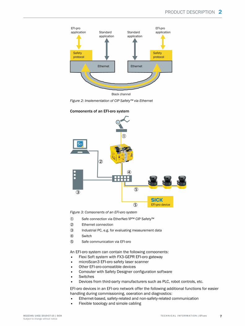
Components of an EFI-pro system
1
EFI-pro device
2
3
4
5
5
Figure 3: Components of an EFI-pro system
1 Safe connection via EtherNet/IP™ CIP Safety™2 Ethernet connection3 Industrial PC, e.g. for evaluating measurement data4 Switch5 Safe communication via EFI-pro
An EFI-pro system can contain the following components:• Flexi Soft system with FX3-GEPR EFI-pro gateway• microScan3 EFI-pro safety laser scanner• Other EFI-pro-compatible devices• Computer with Safety Designer configuration software• Switches• Devices from third-party manufacturers such as PLC, robot controls, etc.
EFI-pro devices in an EFI-pro network offer the following additional functions for easierhandling during commissioning, operation and diagnostics:• Ethernet-based, safety-related and non-safety-related communication• Flexible topology and simple cabling
PRODUCT DESCRIPTION 2
8022345/14OZ/2019-07-15 | SICK T E C H N I C A L I N F O R M A T I O N | EFI-pro 7Subject to change without notice

• Quick commissioning: Easy device identification, addressing and configuration• Quick diagnosis using remote access• Central and quick access to all devices• Time synchronization 1)
Networking of device from third-party manufacturers is also possible via EtherNet/IP™CIP Safety™.
Detailed information on CIP Safety™ can be found at www.odva.org and in the CIPSafety™ “The CIP Networks Library Volume 5: CIP Safety” specifications or ODVA.
1) A time encoder (a UTC server or a device in the project, e.g. a gateway or microScan3) must be available. The IP address of the timeencoder is defined in the project settings.
2 PRODUCT DESCRIPTION
8 T E C H N I C A L I N F O R M A T I O N | EFI-pro 8022345/14OZ/2019-07-15 | SICKSubject to change without notice

3 Network infrastructure
3.1 Devices in the EtherNet/IP™ network
Originator
An originator is the device which initiates the establishment of a connection. The origi‐nator, e.g. a Flexi Soft system with an EFI-pro gateway (FX3-GEPR), sends a connectionrequest to a target.
NOTEDevices with originator function are also called scanners in the EtherNet/IP™ specifica‐tions. The term originator is used consistently in this document.
Target
A target is a device which receives and answers a connection request, e.g. amicroScan3 EFI-pro.
NOTEDevices with target function are also called adapters in the EtherNet/IP™ specifica‐tions. The term target is used consistently in this document.
3.2 Cables
Cabling requirements
• Type: 100Base-TX• Twisted pair Ethernet cable (Cat 5 cable or higher), maximum length 100 m in
accordance with EN 50173• Shielded cables recommended
NOTE
• The use of WLAN connections is not recommended due to long transmission timesand the high susceptibility to malfunctions.
3.3 Switches
Switches can be used in an EFI-pro network. It is possible to implement both safe andnon-safe communication using a switch.
NOTEUsing managed switches is recommended for industrial use to prevent faults and down‐time.Managed switches offer various configuration options for the management, optimiza‐tion and diagnostics of network operation, including the option of dividing up the dataflow in a network into classes with different priorities.
3.4 Subnets and routers
All EFI-pro devices must be in the same sub-network for cyclical communication (forprocess data and safety-related data) (without intermediary routers). Otherwise, com‐munication between the devices will not be possible.
NETWORK INFRASTRUCTURE 3
8022345/14OZ/2019-07-15 | SICK T E C H N I C A L I N F O R M A T I O N | EFI-pro 9Subject to change without notice

The IP address must be assigned either in the same subnet or via USB. A network scanwith Safety Designer to search for EFI-pro devices only works if the computer is in thesame subnet with Safety Designer and the devices.
Acyclical data (configuration, diagnostics) can also be transmitted via a router if the IPaddress of the device is directly entered in Safety Designer. A router can be used tosegment networks or to access the devices from a higher-level network.
3.5 Ports
A network scan using the Safety Designer configuration software is performed via UDP.The EFI-pro devices are configured via TCP. That is why the ports required for these pro‐tocols must be enabled on the computer with the Safety Designer configuration soft‐ware and must not be blocked (e.g. by a firewall).
Table 2: Protocols and required ports
Protocol Ports
UDP 30718 to 30738
TCP 2122 and 2123
3.6 Network topologies
NOTE
• Some EFI-pro-compatible devices have two Ethernet connection which are con‐nected over an internal switch.
The following network topologies are possible:• Star
Point-to-point connections from a switch going to a device• Line
The connection is made from one device to the next. Except for the last device in aline, each of the devices used must have two Ethernet connections.
• A mixed form of star and line
NOTEDevice level ring (DLR)Availability can be increased using a DLR topology. An additional EtherNet/IP™ ringsupervisor is required. This function is included in some controls. EFI-pro devices do notoffer this function.A DLR topology can only be implemented if all used devices have at least two Ethernetconnections. Otherwise the ring cannot be closed.
NOTEEFI-pro does not support simultaneous operation of several fieldbuses in the same net‐work. For example, operation of PROFINET and EFI-pro in the same network is not possi‐ble.
3 NETWORK INFRASTRUCTURE
10 T E C H N I C A L I N F O R M A T I O N | EFI-pro 8022345/14OZ/2019-07-15 | SICKSubject to change without notice

4 Configuration of safe connections
This chapter describes the configuration of the following types of safe connectionsusing the FX3-GEPR:• EFI-pro connections of the FX3-GEPR with microScan3 EFI-pro safety laser scan‐
ners• EFI-pro connections of the FX3-GEPR with other FX3-GEPRs• Connections of the FX3-GEPR with devices from third-party manufacturers via Eth‐
erNet/IP™ CIP Safety™
NOTENon-safe connections via EtherNet/IP™ are also possible with the FX3-GEPR. Com‐pared with safe connections, the FX3-GEPR only acts as a target in non-safe connec‐tions.The FX3-GEPR differs from the functions of the FX0-GENT EtherNet/IP™ gateway.For detailed information on the functions of the FX0-GENT and the FX3-GEPR as well asthe configuration of connections via EtherNet/IP™, see the “Flexi Soft Gateways in theSafety Designer Configuration Software“ operating instructions (SICK part number8018170).
4.1 Basics
Communication options
The FX3-GEPR Flexi Soft gateway can act as both an originator and a target for EFI-proand CIP Safety™. It can also be used as a target for non-safe EtherNet/IP™ connec‐tions. The following connections are therefore possible:
Table 3: Connection options via EFI-pro and EtherNet/IP™ CIP Safety™
Originator Target Type of connection
Flexi Soft (FX3-GEPR EFI-progateway)
EFI-pro-compatible SICKsensors such asmicroScan3 EFI-pro
EFI-pro, safe connection
Flexi Soft (FX3-GEPR EFI-progateway)
Flexi Soft (FX3-GEPR EFI-progateway)
EFI-pro, safe connection
Flexi Soft (FX3-GEPR EFI-progateway)
Device from a third-partymanufacturer
EtherNet/IP™ CIP Safety™, safe con‐nection
CONFIGURATION OF SAFE CONNECTIONS 4
8022345/14OZ/2019-07-15 | SICK T E C H N I C A L I N F O R M A T I O N | EFI-pro 11Subject to change without notice
Originator Target Type of connection
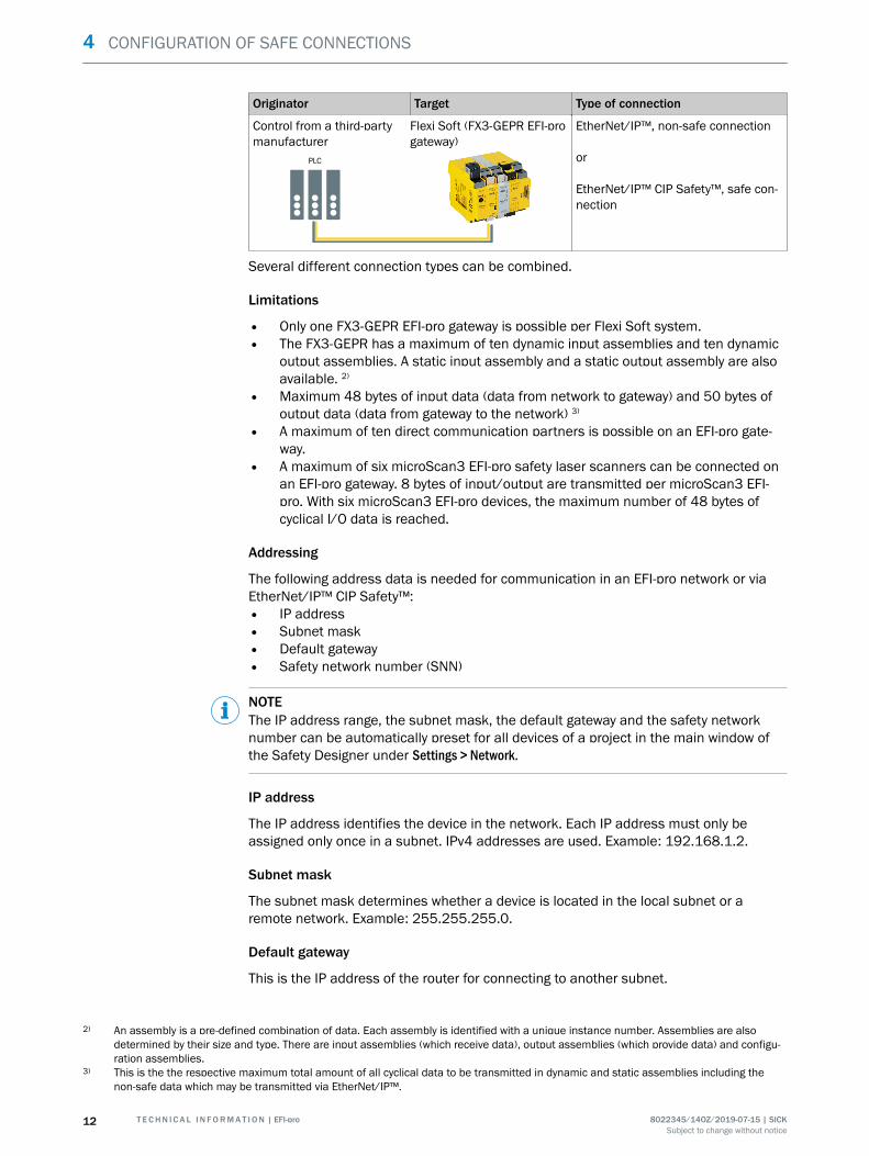
Control from a third-partymanufacturer
Flexi Soft (FX3-GEPR EFI-progateway)
PLC
EtherNet/IP™, non-safe connection
or
EtherNet/IP™ CIP Safety™, safe con‐nection
Several different connection types can be combined.
Limitations
• Only one FX3-GEPR EFI-pro gateway is possible per Flexi Soft system.• The FX3-GEPR has a maximum of ten dynamic input assemblies and ten dynamic
output assemblies. A static input assembly and a static output assembly are alsoavailable. 2)
• Maximum 48 bytes of input data (data from network to gateway) and 50 bytes ofoutput data (data from gateway to the network) 3)
• A maximum of ten direct communication partners is possible on an EFI-pro gate‐way.
• A maximum of six microScan3 EFI-pro safety laser scanners can be connected onan EFI-pro gateway. 8 bytes of input/output are transmitted per microScan3 EFI-pro. With six microScan3 EFI-pro devices, the maximum number of 48 bytes ofcyclical I/O data is reached.
Addressing
The following address data is needed for communication in an EFI-pro network or viaEtherNet/IP™ CIP Safety™:• IP address• Subnet mask• Default gateway• Safety network number (SNN)
NOTEThe IP address range, the subnet mask, the default gateway and the safety networknumber can be automatically preset for all devices of a project in the main window ofthe Safety Designer under Settings > Network.
IP address
The IP address identifies the device in the network. Each IP address must only beassigned only once in a subnet. IPv4 addresses are used. Example: 192.168.1.2.
Subnet mask
The subnet mask determines whether a device is located in the local subnet or aremote network. Example: 255.255.255.0.
Default gateway
This is the IP address of the router for connecting to another subnet.
2) An assembly is a pre-defined combination of data. Each assembly is identified with a unique instance number. Assemblies are alsodetermined by their size and type. There are input assemblies (which receive data), output assemblies (which provide data) and configu‐ration assemblies.
3) This is the the respective maximum total amount of all cyclical data to be transmitted in dynamic and static assemblies including thenon-safe data which may be transmitted via EtherNet/IP™.
4 CONFIGURATION OF SAFE CONNECTIONS
12 T E C H N I C A L I N F O R M A T I O N | EFI-pro 8022345/14OZ/2019-07-15 | SICKSubject to change without notice

Safety network number (SNN)
Each device in an EtherNet/IP™ CIP Safety™ network or in an EFI-pro network must beconfigured with an SNN. The SNN is a hexadecimal number consisting of 6 bytes. Exam‐ple: 432D_0226_A17B.
Each device which, as an originator, establishes a connection to a target should havethe same SNN as the target.
NOTEThe use of several SNNs within a project is possible in certain cases, but is not recom‐mended.
4.2 EFI-pro
4.2.1 Flexi Soft with microScan3 EFI-pro
Hardware
A FX3-GEPR Flexi Soft gateway (EFI-pro gateway) is used as an originator. Up to sixmicroScan3 EFI-pro safety laser scanners with full functionality can be connected astargets.
Two RJ45 interfaces for connecting the devices are available on the EFI-pro gateway.
The microScan3 EFI-pro safety laser scanners can be connected in a line topology. Thedefault Ethernet cables (M12, 4-pin, D-coded) are used here. Alternatively, a star topol‐ogy can be implemented using a switch.
Software configuration
Creating the devices in Safety Designer1. In the Safety Designer main window, create one or more microScan3 EFI-pro safety
laser scanners and a modular Flexi Soft safety controller as devices.2. An FX3-GEPR EFI-pro gateway can be added in the device window of the Flexi Soft
safety controller.
All devices must be in the same subnet and have the same safety network number(SNN).
Connecting devices together
There are two ways to connect a gateway and a safety laser scanner together:• Click on Connections in the Safety Designer main window
This is the recommended procedure.• In the Flexi Soft safety controller device window
This procedure is required, for example, to edit or replace existing connections or ifEFI-pro devices in more complex projects are to be connected with several FlexiSoft systems.
Connecting the devices in the Safety Designer main window
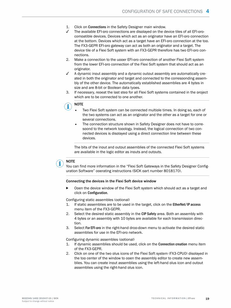
1. Click on Connections in the Safety Designer main window.✓ The available EFI-pro connections are displayed on the device tiles of all EFI-pro-
compatible devices. Devices which act as an originator have an EFI-pro connectionat the bottom. Devices which act as a target have an EFI-pro connection at the top.The FX3-GEPR EFI-pro gateway can act as both an originator and a target. Thedevice tile of a Flexi Soft system with an FX3-GEPR therefore has two EFI-pro con‐nections.
2. Make a connection to the EFI-pro connection of a microScan3 EFI-pro from thelower EFI-pro connection of the Flexi Soft system.
✓ An EFI-pro connection is established between the two devices.
CONFIGURATION OF SAFE CONNECTIONS 4
8022345/14OZ/2019-07-15 | SICK T E C H N I C A L I N F O R M A T I O N | EFI-pro 13Subject to change without notice

3. Repeat the last step for all safety laser scanners in the project.
Figure 4: EFI-pro connections in the Safety Designer main window
NOTEThe connection structure shown in Safety Designer does not have to correspond tothe network topology. Instead, the logical connection of two connected devices isdisplayed using a direct connection line between these devices.If there is a Flexi Soft system with several connected microScan3 EFI-pro devices,this results in a star-shaped connection structure in Safety Designer, even if sev‐eral or all microScan3 are cabled together in a linear manner.
✓ An assembly is automatically created in the FX3-GEPR corresponding to each inputand output assembly of a microScan3 EFI-pro and connected to the assembly inthe microScan3 EFI-pro. The tag names from the assemblies of the microScan3EFI-pro are then automatically adopted the assemblies in the FX3-GEPR.The data of the input and output assemblies of the microScan3 EFI-pro safetylaser scanner connected to the Flexi Soft system is available as inputs and out‐puts in the logic editor of the Flexi Soft system.
NOTEYou can find more information in the “Flexi Soft Gateways in the Safety Designer Config‐uration Software” operating instructions (SICK part number 8018170).
Connecting the devices in the Flexi Soft device window
1. In the device window of the Flexi Soft system, click on Configuration and then on theConnection creation menu item of the FX3-GEPR EFI-pro gateway.
✓ The Flexi Soft system (FX3-CPU0) is displayed at the top in the center of the win‐
4 CONFIGURATION OF SAFE CONNECTIONS
14 T E C H N I C A L I N F O R M A T I O N | EFI-pro 8022345/14OZ/2019-07-15 | SICKSubject to change without notice

dow. The other devices available in the project are initially displayed in the lowerarea of the device window.
Figure 5: microScan3 EFI-pro in connection creation of the FX3-GEPR
2. Double-click on the desired microScan3 EFI-pro to include it in connection cre‐ation.
✓ At the top left, the output assembly (data to the gateway) of the selectedmicroScan3 EFI-pro is displayed, at the top right is the input assembly (data fromthe gateway).
3. Drag the assemblies of the microScan3 EFI-pro to the opposite plus icon of theFlexi Soft system using drag-and-drop.
✓ An assembly is created in the FX3-GEPR corresponding to each input and outputassembly of a microScan3 EFI-pro and connected to the assembly in themicroScan3 EFI-pro. The tag names from the assemblies of the microScan3 EFI-pro are then automatically adopted the assemblies in the FX3-GEPR.
NOTEIf the FX3-GEPR was already connected with a microScan3 EFI-pro, then it mightalready contain one or several corresponding assemblies. Instead of creating newassemblies, you can connect the existing assemblies to the assemblies of themicroScan3 EFI-pro via drag-and-drop.
CONFIGURATION OF SAFE CONNECTIONS 4
8022345/14OZ/2019-07-15 | SICK T E C H N I C A L I N F O R M A T I O N | EFI-pro 15Subject to change without notice
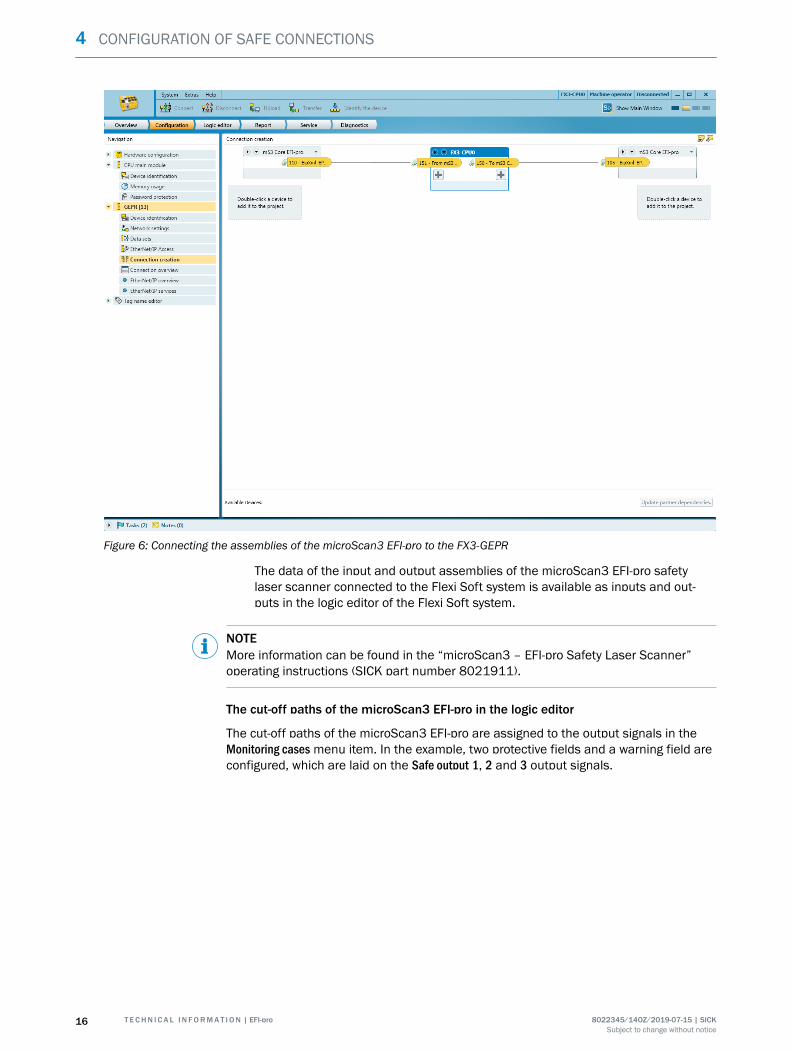
Figure 6: Connecting the assemblies of the microScan3 EFI-pro to the FX3-GEPR
The data of the input and output assemblies of the microScan3 EFI-pro safetylaser scanner connected to the Flexi Soft system is available as inputs and out‐puts in the logic editor of the Flexi Soft system.
NOTEMore information can be found in the “microScan3 – EFI-pro Safety Laser Scanner”operating instructions (SICK part number 8021911).
The cut-off paths of the microScan3 EFI-pro in the logic editor
The cut-off paths of the microScan3 EFI-pro are assigned to the output signals in theMonitoring cases menu item. In the example, two protective fields and a warning field areconfigured, which are laid on the Safe output 1, 2 and 3 output signals.
4 CONFIGURATION OF SAFE CONNECTIONS
16 T E C H N I C A L I N F O R M A T I O N | EFI-pro 8022345/14OZ/2019-07-15 | SICKSubject to change without notice
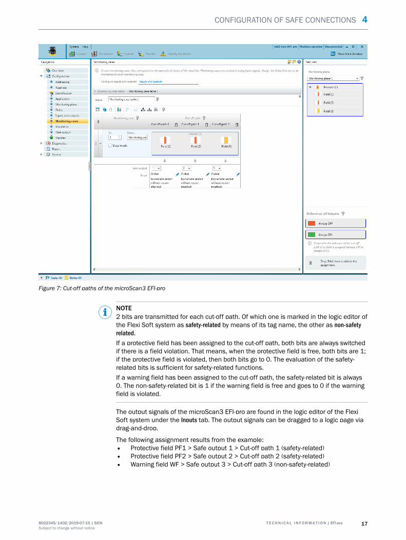
Figure 7: Cut-off paths of the microScan3 EFI-pro
NOTE2 bits are transmitted for each cut-off path. Of which one is marked in the logic editor ofthe Flexi Soft system as safety-related by means of its tag name, the other as non-safetyrelated.If a protective field has been assigned to the cut-off path, both bits are always switchedif there is a field violation. That means, when the protective field is free, both bits are 1;if the protective field is violated, then both bits go to 0. The evaluation of the safety-related bits is sufficient for safety-related functions.If a warning field has been assigned to the cut-off path, the safety-related bit is always0. The non-safety-related bit is 1 if the warning field is free and goes to 0 if the warningfield is violated.
The output signals of the microScan3 EFI-pro are found in the logic editor of the FlexiSoft system under the Inputs tab. The output signals can be dragged to a logic page viadrag-and-drop.
The following assignment results from the example:• Protective field PF1 > Safe output 1 > Cut-off path 1 (safety-related)• Protective field PF2 > Safe output 2 > Cut-off path 2 (safety-related)• Warning field WF > Safe output 3 > Cut-off path 3 (non-safety-related)
CONFIGURATION OF SAFE CONNECTIONS 4
8022345/14OZ/2019-07-15 | SICK T E C H N I C A L I N F O R M A T I O N | EFI-pro 17Subject to change without notice

Figure 8: Cut-off paths of the microScan3 EFI-pro in the logic editor
4.2.2 Flexi Soft with Flexi Soft
Hardware
If two Flexi Soft stations are each connected to a FX3-GEPR EFI-pro gateway, one of thetwo gateways acts as an originator and the other as a target for this connection.
Software configuration
Creating the devices in Safety Designer1. In the main window of the Safety Designer, create the desired number of modular
Flexi Soft safety controllers as devices.2. An FX3-GEPR EFI-pro gateway can be added to each Flexi Soft safety controller.
All devices must be in the same subnet and have the same safety network number(SNN).
Connecting devices together
There are two ways to connect two gateways:• Click on Connections in the Safety Designer main window.
This is the recommended procedure for simple applications.• In the Flexi Soft safety controller device window
For example, this procedure is required to edit or replace existing connections or ifthe static assemblies are to be used or if several assemblies or assemblies otherthat the automatically created ones are needed.
Connecting the devices in the Safety Designer main window
4 CONFIGURATION OF SAFE CONNECTIONS
18 T E C H N I C A L I N F O R M A T I O N | EFI-pro 8022345/14OZ/2019-07-15 | SICKSubject to change without notice
1. Click on Connections in the Safety Designer main window.✓ The available EFI-pro connections are displayed on the device tiles of all EFI-pro-
compatible devices. Devices which act as an originator have an EFI-pro connectionat the bottom. Devices which act as a target have an EFI-pro connection at the top.The FX3-GEPR EFI-pro gateway can act as both an originator and a target. Thedevice tile of a Flexi Soft system with an FX3-GEPR therefore has two EFI-pro con‐nections.
2. Make a connection to the upper EFI-pro connection of another Flexi Soft systemfrom the lower EFI-pro connection of the Flexi Soft system that should act as anoriginator.
✓ A dynamic input assembly and a dynamic output assembly are automatically cre‐ated in both the originator and target and connected to the corresponding assem‐bly of the other device. The automatically established assemblies are 4 bytes insize and are 8-bit or Boolean data types.
3. If necessary, repeat the last step for all Flexi Soft systems contained in the projectwhich are to be connected to one another.
NOTE
• Two Flexi Soft system can be connected multiple times. In doing so, each ofthe two systems can act as an originator and the other as a target for one orseveral connections.
• The connection structure shown in Safety Designer does not have to corre‐spond to the network topology. Instead, the logical connection of two con‐nected devices is displayed using a direct connection line between thesedevices.
The bits of the input and output assemblies of the connected Flexi Soft systemsare available in the logic editor as inputs and outputs.
NOTEYou can find more information in the “Flexi Soft Gateways in the Safety Designer Config‐uration Software” operating instructions (SICK part number 8018170).
Connecting the devices in the Flexi Soft device window
b Open the device window of the Flexi Soft system which should act as a target andclick on Configuration.
Configuring static assembles (optional)1. If static assemblies are to be used in the target, click on the EtherNet/IP access
menu item of the FX3-GEPR.2. Select the desired static assembly in the CIP Safety area. Both an assembly with
4 bytes or an assembly with 10 bytes are available for each transmission direc‐tion.
3. Select For EFI-pro in the right-hand drop-down menu to activate the desired staticassemblies for use in the EFI-pro network.
Configuring dynamic assembles (optional)1. If dynamic assemblies should be used, click on the Connection creation menu item
of the FX3-GEPR.2. Click on one of the two plus icons of the Flexi Soft system (FX3-CPU0) displayed in
the top center of the window to open the assembly editor to create new assem‐blies. You can create input assemblies using the left-hand plus icon and outputassemblies using the right-hand plus icon.
CONFIGURATION OF SAFE CONNECTIONS 4
8022345/14OZ/2019-07-15 | SICK T E C H N I C A L I N F O R M A T I O N | EFI-pro 19Subject to change without notice

Figure 9: The assembly editor
3. Enter a name for the new assembly, select the size in bytes and assign all bytes toa data type from the left-hand selection list using drag-and-drop. The 8 bit datatype is usually suitable.
NOTEAn assembly can contain various data types.
4 CONFIGURATION OF SAFE CONNECTIONS
20 T E C H N I C A L I N F O R M A T I O N | EFI-pro 8022345/14OZ/2019-07-15 | SICKSubject to change without notice

Figure 10: Defining an assembly in the assembly editor
4. Click on Save to close the editor and create the new assembly.5. Create all required assemblies in this way.
Establishing EFI-pro connections1. Open the device window of the Flexi Soft system which should act as an originator
and click on Configuration.2. If static assemblies are to be used in the originator, configure these as described.3. Then click on the Connection creation menu item of the FX3-GEPR EFI-pro gateway.✓ The Flexi Soft system as FX3-CPU0 acting as an originator is displayed at the top
center of the window. The devices available as targets in the project are initiallydisplayed in the lower area of the device window.
4. Double-click on the desired Flexi Soft system to include it in the establishment ofthe connection as the target.
✓ The output assemblies of the newly-added Flexi Soft system is shown at the topright, the input assemblies at the top left.
5. Drag the input and output assemblies of the targets which are to be connected tothe opposite plus icon of the originator using drag-and-drop.
✓ A dynamic assembly is created in the originator corresponding to each input andoutput assembly of the target and connected to the target assembly. The tagnames from the assemblies of the target are then automatically adopted in theassemblies in the originator.
CONFIGURATION OF SAFE CONNECTIONS 4
8022345/14OZ/2019-07-15 | SICK T E C H N I C A L I N F O R M A T I O N | EFI-pro 21Subject to change without notice

NOTE
• Instead of creating new dynamic assemblies, you can connect existing staticor dynamic assemblies to one another using drag-and-drop.
• Static assemblies must be configured under EtherNet/IP access of the respec‐tive FX3-GEPR before they can be used.
• Assemblies can only be connected if the size and data type match.• The Flexi Soft system in whose device window the connection was estab‐
lished acts as an originator for each connection between two assemblies.• If several assemblies of two Flexi Soft system are connected to one another,
you can select individually for each connection which of the two Flexi Soft sys‐tems should act as an originator.
The data of the connected input and output assemblies is available in the logiceditors of the two connected Flexi Soft systems as inputs and outputs.
4.2.3 Editing EFI-pro connections
Editing connection settings
1. Open the device window of the originator of the connection in question.2. Click on Configuration and then on the Connection creation menu item of the FX3-
GEPR.3. Move the mouse cursor to the connection to be edited. A pop-up dialog window
appears.4. In this pop-up dialog window of the connection line, click on Edit. The Settings of the
safety connection dialog window opens.
The following parameters can be configured:• Connection name• RPI• Max. lost packets• Network delay• SCID mechanism
The resulting response time via the network of the connection is also shown.
NOTEThese parameters are also displayed under the Connection overview menu item of theFX3-GEPR in table form for all connections for which the FX3-GEPR acts as an origina‐tor and can also be edited there. The cycle times between the network and the mainmodule (CPU) are also displayed here.
Connection name
The preset name of the connection can be changed here if needed.
RPI
The requested packet interval (RPI) determines how often data is sent. It is specified in mil‐liseconds and influences the response time.
Max. lost packets
The number of maximum lost packets determines the tolerance against transmissionfaults. It influences the response time.
Network delay
The network delay enables additional fault tolerance of the connection. It is specified inpercent of the requested packet interval (RPI) and influences the response time.
SCID mechanism
4 CONFIGURATION OF SAFE CONNECTIONS
22 T E C H N I C A L I N F O R M A T I O N | EFI-pro 8022345/14OZ/2019-07-15 | SICKSubject to change without notice

This is optional additional protection against unwanted changes to the configuration. Ifthe Use SCID mechanical is activated, the originator compares its safety configuration ID(SCID) with the SCID saved in the target. If the checksums of the two SCIDs do notmatch, meaning the configuration of both devices has been changed, no communica‐tion occurs.
The SCID is a combination of a checksum and the date stamp of the safety configura‐tion. It can be read in the device window of the Flexi Soft system under Configuration,GEPR, EtherNet/IP overview.
NOTEThe Use SCID mechanism option cannot be configured in the Connection overview but only inthe Safety connection settings under Connection creation.
Response time via network
The response time via the network is the maximum time which can pass until the transmit‐ted data is successfully updated. If this response time is exceeded, it is evaluated as afault.
The response time is calculated using the following formula:
Response time = RPI × max. lost packets + RPI × network delay/100
Connection status
Under the Connection overview menu item of the FX3-GEPR, the connection status is shownfor all connections for which the FX3-GEPR acts as an originator.
Deleting the connection
Deleting connection in the main window1. Click on Connections in the Safety Designer main window.2. Move the mouse cursor to the connection you want to delete. The connection line
is highlighted in blue and a recycling bin icon appears on the target connection.3. Click on the recycling bin icon to delete the connection.
Or:
4. Click on Delete in the context menu of the connection line.
Deleting connection in the device window1. Open the device window of the originator of the connection you want to delete.2. Click on Configuration and then on the Connection creation menu item of the FX3-
GEPR.3. Move the mouse cursor to the connection you want to delete. A pop-up dialog win‐
dow appears.4. In this pop-up dialog window of the connection line, click on Delete.
NOTEThe assemblies whose connection was deleted remain. They have to be deleted sepa‐rately in the Connection creation of the FX3-GEPR if desired.
CONFIGURATION OF SAFE CONNECTIONS 4
8022345/14OZ/2019-07-15 | SICK T E C H N I C A L I N F O R M A T I O N | EFI-pro 23Subject to change without notice
4.3 EtherNet/IP™ CIP Safety™
4.3.1 Flexi Soft with devices from third-party manufacturers
NOTESICK provides example configuration files on request for easy configuration of variousdevices from third-party manufacturers. Information is available from your SICK sub‐sidiary. Current versions of the Safety Designers have sample files for the generic Ether‐Net/IP CIP safety device.
Hardware
An FX3-GEPR EFI-pro gateway (EFI-pro gateway) can establish a connection with adevices of a third-party manufacturer via EtherNet/IP™ CIP Safety™. The device of thethird-party manufacturer acts as a target in this connection.
Software configuration
The generic EtherNet/IP CIP safety device is available in the device catalog of the SafetyDesigner for connecting an EFI-pro gateway with devices from third-party manufacturersvia EtherNet/IP™ CIP Safety™.
Safety functions, such as remote I/O or robots can be used with the help of the genericEtherNet/IP CIP safety device.
Creating a generic Ethernet/IP CIP safety deviceb Double-click on Generic Ethernet/IP CIP safety device in the device catalog in Safety
Designer.✓ A device tile for the generic Ethernet/IP CIP safety device is added in the device
overview.
Configuring a generic Ethernet/IP CIP safety device1. In Safety Designer, click on the device tile for the generic Ethernet/IP CIP safety device
to open the associated device window.2. In the General tab, make the following settings:
4 CONFIGURATION OF SAFE CONNECTIONS
24 T E C H N I C A L I N F O R M A T I O N | EFI-pro 8022345/14OZ/2019-07-15 | SICKSubject to change without notice

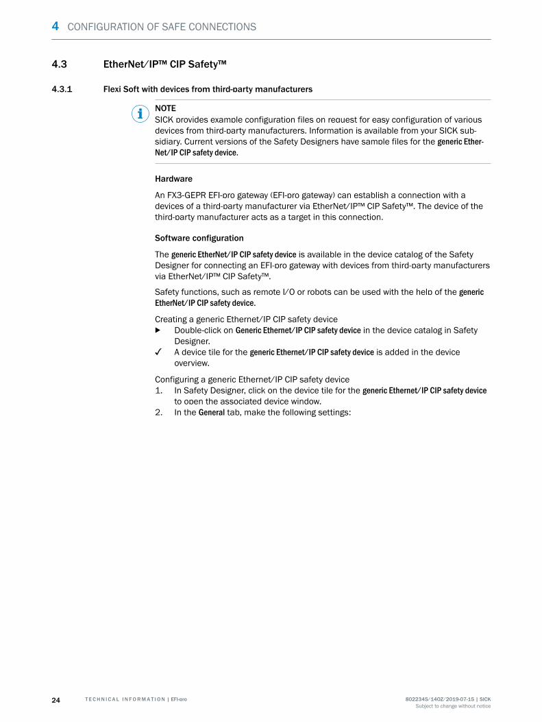
Figure 11: Configuration window of the generic Ethernet/IP CIP safety device, general
w Enter a device name and assign an image to the device where applicable.w Enter the device IP address and the project safety network number.w Enter the general characteristics of the new device (supplier, product type, prod‐
uct code, main version, and minor version). You can find this data in the manualor the EDS file for the device. 4)
Using this characteristic data, a version test is performed when establishingthe communication between the originator, i.e. the FX3-GEPR, and the third-party manufacturer device as a target. In doing so, the originator sends thecharacteristic data and the mode of the version test to the target. The targettests the characteristic data and reports the result of the version test to theoriginator. If the version test fails, no connection can be established.
w Specify the mode for the version test.• Compatible module: The target uses the received characteristic data to
test whether it is identical or compatible with the device expected by theoriginator. The type of compatibility testing is dependent only on the tar‐get.
• Exact match: A connection can only be made if the characteristic datasent from the originator exactly matches the characteristic data of thetarget.
w Optionally, enter a user and/or a comment.3. In the Default settings tab, make the following settings:
4) The EZ-EDS software of ODVA can be used to read the EDS file. It is not possible to read in the EDS file using Safety Designer. The datamust be manually entered in the configuration window of the generic Ethernet/IP CIP safety device.
CONFIGURATION OF SAFE CONNECTIONS 4
8022345/14OZ/2019-07-15 | SICK T E C H N I C A L I N F O R M A T I O N | EFI-pro 25Subject to change without notice
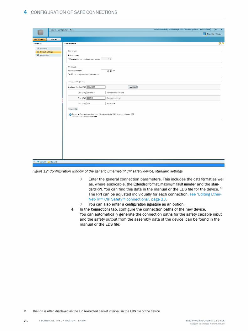
Figure 12: Configuration window of the generic Ethernet/IP CIP safety device, standard settings
w Enter the general connection parameters. This includes the data format as wellas, where applicable, the Extended format, maximum fault number and the stan‐dard RPI. You can find this data in the manual or the EDS file for the device. 5)
The RPI can be adjusted individually for each connection, see "Editing Ether‐Net/IP™ CIP Safety™ connections", page 33.
w You can also enter a configuration signature as an option.4. In the Connections tab, configure the connection paths of the new device.
You can automatically generate the connection paths for the safety capable inputand the safety output from the assembly data of the device (can be found in themanual or the EDS file).
5) The RPI is often displayed as the EPI (expected packet interval) in the EDS file of the device.
4 CONFIGURATION OF SAFE CONNECTIONS
26 T E C H N I C A L I N F O R M A T I O N | EFI-pro 8022345/14OZ/2019-07-15 | SICKSubject to change without notice

Figure 13: Generating connection paths
Alternatively, you can enter the hexadecimal connections paths directly underDefine connection path.
CONFIGURATION OF SAFE CONNECTIONS 4
8022345/14OZ/2019-07-15 | SICK T E C H N I C A L I N F O R M A T I O N | EFI-pro 27Subject to change without notice

Figure 14: Entering connection path directly
You can find the connection path for the safety capable input and the safety out‐put in the EDS file under Connection Manager. The connection paths contain infor‐mation about classes, instances and attributes which are needed for establish‐ment of the connection.
4 CONFIGURATION OF SAFE CONNECTIONS
28 T E C H N I C A L I N F O R M A T I O N | EFI-pro 8022345/14OZ/2019-07-15 | SICKSubject to change without notice

Figure 15: Connection path in the EDS file in EZ-EDS
NOTERegardless of whether the connection path is entered manually or generated bySafety Designer, the assembly size must always be entered in byte.
Connecting devices together
There are two ways to connect a gate with a device from a third-party manufacturer:• Click on Connections in the Safety Designer main window.
This is the recommended procedure for simple applications.• In the Flexi Soft safety controller device window
For example, this procedure is required to edit or replace existing connections or ifthe static assemblies of the FX3-GEPR are to be used or if several assemblies areto be connected.
Connecting the devices in the Safety Designer main window
1. Click on Connections in the Safety Designer main window.✓ The available EFI-pro connections are displayed on the device tiles of all suitable
devices. Devices which act as an originator have an EFI-pro connection at the bot‐tom. Devices which act as a target have an EFI-pro connection at the top. The FX3-GEPR EFI-pro gateway can act as both an originator and a target. The device tile ofa Flexi Soft system with an FX3-GEPR therefore has two EFI-pro connections.Devices from third-party manufacturers can only work as a target and thereforehave only one EFI-pro connection at the top.
CONFIGURATION OF SAFE CONNECTIONS 4
8022345/14OZ/2019-07-15 | SICK T E C H N I C A L I N F O R M A T I O N | EFI-pro 29Subject to change without notice

2. Make a connection to the EFI-pro connection of the third-part manufacturer devicefrom the lower EFI-pro connection of the Flexi Soft system that should act as anoriginator.
✓ In the FX3-GEPR, a dynamic input assembly and a dynamic output assembly areautomatically created and connected with the respective assembly of the third-party manufacturer device. The automatically created assemblies correspond tothe size of the assemblies of the third-party manufacturer devices and are 8-bit orBoolean types.The bits of the input and output assemblies of the connected devices are availablein the logic editor as inputs and outputs.
NOTEYou can find more information in the “Flexi Soft Gateways in the Safety Designer Config‐uration Software” operating instructions (SICK part number 8018170).
Connecting the devices in the Flexi Soft device window
b Open the device window of the new Flexi Soft system and click on Configuration.
Configuring static assembles (optional)1. If static assemblies of the FX3-GEPR should be used, click on the Ethernet access
menu item of the FX3-GEPR.2. Select the desired static assembly in the CIP Safety area. An alternative assembly
with 4 bytes or an assembly with 10 bytes are available for each transmissiondirection.
3. Select For EFI-pro in the right-hand drop-down menu to activate the desired staticassemblies for use in during connection creation.
Configuring dynamic assembles (optional)1. If dynamic assemblies should be used, click on the Connection creation menu item
of the FX3-GEPR.2. Click on one of the two plus icons to open the assembly editor to create new
assemblies. You can create input assemblies using the left-hand plus icon andoutput assemblies using the right-hand plus icon.
4 CONFIGURATION OF SAFE CONNECTIONS
30 T E C H N I C A L I N F O R M A T I O N | EFI-pro 8022345/14OZ/2019-07-15 | SICKSubject to change without notice
Figure 16: The assembly editor
3. Enter a name for the new assembly, select the size in bytes and assign all bytes toa data type from the left-hand selection list using drag-and-drop. The 8 bit datatype is usually suitable.
NOTEAn assembly can contain various data types.
CONFIGURATION OF SAFE CONNECTIONS 4
8022345/14OZ/2019-07-15 | SICK T E C H N I C A L I N F O R M A T I O N | EFI-pro 31Subject to change without notice

Figure 17: Defining an assembly in the assembly editor
4. Click on Save to close the editor and create the new assembly.5. Create all required assemblies in this way.
Establishing a connection1. Open the device window of the new Flexi Soft system and click on Configuration. In
connections with third-party manufacturer devices, the Flexi Soft system alwaysacts as an originator and the other device as a target.
2. If static assemblies are to be used in the originator, configure these as described.3. Then click on the Connection creation menu item of the FX3-GEPR EFI-pro gateway.
The Flexi Soft system is displayed as FX3-CPU0 in the center of the window.✓ The devices available as targets in the project are initially displayed in the lower
area of the device window.4. Double-click on the desired device to include it in the establishment of the connec‐
tion as the target.✓ The output assemblies of the newly-added device is shown at the top right, the
input assemblies at the top left.5. Drag the input and output assemblies of the targets which are to be connected to
the opposite plus icon of the originator using drag-and-drop.✓ A dynamic assembly is created in the originator corresponding to each input and
output assembly of the target and connected to the target assembly. The tagnames from the assemblies of the target are then automatically adopted in theassemblies in the originator.
4 CONFIGURATION OF SAFE CONNECTIONS
32 T E C H N I C A L I N F O R M A T I O N | EFI-pro 8022345/14OZ/2019-07-15 | SICKSubject to change without notice

NOTE
• Instead of creating new dynamic assemblies, already existing static ordynamic assemblies of the FX3-GEPR can be connected to the assemblies ofthe target using drag-and-drop.
• Static assemblies must be configured under EtherNet/IP access of the respec‐tive FX3-GEPR before they can be used.
• Two assemblies can only be connected if the size and data type match.
The data of the connected input and output assemblies are available in the FlexiSoft logic editor as inputs and outputs.
4.3.2 Editing EtherNet/IP™ CIP Safety™ connections
Editing connection settings
1. Open the device window of the originator of the connection in question.2. Click on Configuration and then on the Connection creation menu item of the FX3-
GEPR.3. Move the mouse cursor to the connection to be edited. A pop-up dialog window
appears.4. In this pop-up dialog window of the connection line, click on Edit. The Settings of the
safety connection dialog window opens.
The following parameters can be configured:• Connection name• RPI• Max. lost packets• Network delay• SCID mechanism
The resulting response time via the network of the connection is also shown.
NOTEThese parameters are also displayed under the Connection overview menu item of theFX3-GEPR in table form for all connections for which the FX3-GEPR acts as an origina‐tor and can also be edited there. The cycle times between the network and the mainmodule (CPU) are also displayed here.
Connection name
The preset name of the connection can be changed here if needed.
RPI
The requested packet interval (RPI) determines how often data is sent. It is specified in mil‐liseconds and influences the response time.
Max. lost packets
The number of maximum lost packets determines the tolerance against transmissionfaults. It influences the response time.
Network delay
The network delay enables additional fault tolerance of the connection. It is specified inpercent of the requested packet interval (RPI) and influences the response time.
SCID mechanism
CONFIGURATION OF SAFE CONNECTIONS 4
8022345/14OZ/2019-07-15 | SICK T E C H N I C A L I N F O R M A T I O N | EFI-pro 33Subject to change without notice
This is optional additional protection against unwanted changes to the configuration. Ifthe Use SCID mechanical is activated, the originator compares its safety configuration ID(SCID) with the SCID saved in the target. If the checksums of the two SCIDs do notmatch, meaning the configuration of both devices has been changed, no communica‐tion occurs.
The SCID is a combination of a checksum and the date stamp of the safety configura‐tion. It can be read in the device window of the Flexi Soft system under Configuration,GEPR, EtherNet/IP overview.
The SCID of a generic EtherNet/IP CIP safety device can be read and edited under Standardsettings.
NOTEThe Use SCID mechanism option cannot be configured in the Connection overview but only inthe Safety connection settings under Connection creation.
Response time via network
The response time via the network is the maximum time which can pass until the transmit‐ted data is successfully updated. If this response time is exceeded, it is evaluated as afault.
The response time is calculated using the following formula:
Response time = RPI × max. lost packets + RPI × network delay/100
Connection status
Under the Connection overview menu item of the FX3-GEPR, the connection status is shownfor all connections for which the FX3-GEPR acts as an originator.
Deleting the connection
Deleting connection in the main window1. Click on Connections in the Safety Designer main window.2. Move the mouse cursor to the connection you want to delete. The connection line
is highlighted in blue and a recycling bin icon appears on the target connection.3. Click on the recycling bin icon to delete the connection.
Or:
4. Click on Delete in the context menu of the connection line.
Deleting connection in the device window1. Open the device window of the originator of the connection you want to delete.2. Click on Configuration and then on the Connection creation menu item of the FX3-
GEPR.3. Move the mouse cursor to the connection you want to delete. A pop-up dialog win‐
dow appears.4. In this pop-up dialog window of the connection line, click on Delete.
NOTEThe assemblies whose connection was deleted remain. They have to be deleted sepa‐rately in the Connection creation of the FX3-GEPR if desired.
4 CONFIGURATION OF SAFE CONNECTIONS
34 T E C H N I C A L I N F O R M A T I O N | EFI-pro 8022345/14OZ/2019-07-15 | SICKSubject to change without notice
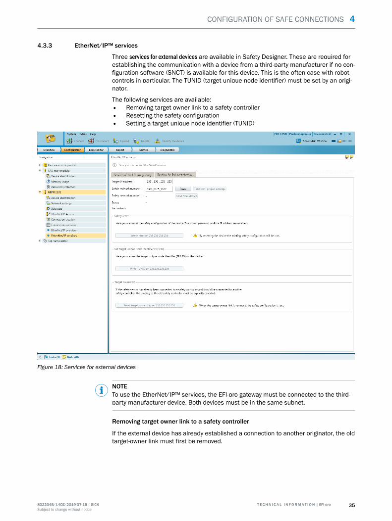
4.3.3 EtherNet/IP™ services
Three services for external devices are available in Safety Designer. These are required forestablishing the communication with a device from a third-party manufacturer if no con‐figuration software (SNCT) is available for this device. This is the often case with robotcontrols in particular. The TUNID (target unique node identifier) must be set by an origi‐nator.
The following services are available:• Removing target owner link to a safety controller• Resetting the safety configuration• Setting a target unique node identifier (TUNID)
Figure 18: Services for external devices
NOTETo use the EtherNet/IP™ services, the EFI-pro gateway must be connected to the third-party manufacturer device. Both devices must be in the same subnet.
Removing target owner link to a safety controller
If the external device has already established a connection to another originator, the oldtarget-owner link must first be removed.
CONFIGURATION OF SAFE CONNECTIONS 4
8022345/14OZ/2019-07-15 | SICK T E C H N I C A L I N F O R M A T I O N | EFI-pro 35Subject to change without notice

NOTEPrerequisites for removing the target-owner link:• The external device (target) must be in Idle mode.• The external device must not have a current connection to another originator.
If there is still a connection to an originator:b If applicable, separate the connection to the originator by disconnecting the com‐
munication cable.
Or:b Transmit an empty configuration to the EFI-pro gateway.
1. Enter the current IP address of the target in Safety Designer.2. Click on the Target-owner link to [IP address] button.
Resetting the safety configuration
If a TUNID is already configured in a device, it can not simply be overwritten. In thiscase, the safety configuration must be reset.
In order to reset the safety configuration of the external device, a type 2 safety reset isexecuted in line with the EtherNet/IP™ CIP Safety™ specifications.
1. Enter the current IP address of the target in Safety Designer.2. Click on the Reset safety configuration to [IP address] button.✓ The safety configuration of the external device is irrevocably deleted.
NOTICEBy resetting, the device loses its existing safety configuration. If required, the devicemust then be reconfigured using the configuration software provided by the manufac‐turer.
Setting TUNID
To set a new TUNID, the current IP address of the external device and the new SNNmust be entered.
1. Enter the current IP address of the target in Safety Designer.2. Enter the new SNN of the target in Safety Designer.3. Click on the Write TUNID on [IP address] button.✓ The new TUNID is set in the external device.
Transitions of the EtherNet/IP™ device statuses
A device can be in the following states or brought to these states using the SafetyDesigner or the configuration software of the third-party manufacturer device:
Table 4: Transitions of the EtherNet/IP™ device statuses
Previous state Action or condition Resulting state
The device performs a self-test after switching on. If thisis successful, there are threeoptions.
Device contains TUNID andconfiguration
Idle
The device contains no TUNID Waiting for valid TUNID
Device contains TUNID, but noconfiguration
Configuring
Waiting for valid TUNID Set TUNID Configuring 1)
Configuring Reset the safety configuration Waiting for valid TUNID
Write the safety configurationin the device 2)
Idle
4 CONFIGURATION OF SAFE CONNECTIONS
36 T E C H N I C A L I N F O R M A T I O N | EFI-pro 8022345/14OZ/2019-07-15 | SICKSubject to change without notice

Previous state Action or condition Resulting state
Idle Reset the safety configuration Waiting for valid TUNID
Remove the target-owner link Configuring 1)
Establishment of connectionby originator 3)
Executing
1) Many robot controls have a fixed pre-configuration. After setting a TUNID or after resetting the safety con‐figuration, the devices skip the Configuring state and change directly to Idle.
2) This is carried out using the configuration software of the external device if necessary.3) E.g. by an FX3-GEPR EFI-pro gateway.
CONFIGURATION OF SAFE CONNECTIONS 4
8022345/14OZ/2019-07-15 | SICK T E C H N I C A L I N F O R M A T I O N | EFI-pro 37Subject to change without notice

5 Technical data
5.1 Response time of an EFI-pro system
All paths must be considered for calculation of the response times within an EFI-prosystem.
E1
Digital
inputs
A1
Digital
outputs
E2
Input from
FX3-GEPR
CPUx
Logic &
routing
A2
Output to
FX3-GEPR
EFI-pro EFI-pro
FLEXBUS+ FLEXBUS+
FLEXBUS+ FLEXBUS+
Figure 19: Response times in an EFI-pro system
FLEXBUS+
Internal backplane bus of the Flexi Soft system
Calculation of the response time
The following table can be used to calculate the response time of the connection pathswithin the Flexi Soft system.
Table 5: Calculation of the maximum response time of the Flexi Soft system
1. Inputs Response time of theobserved input in the signalpath
E1 or E2 (see correspondingtable)
2. Logic a) Response time of themain module logic(FX3-CPUx logic)
2 × logic execution time 1)
Delay due to logic application2) (e.g. switch-on delay orswitch-off delay functionblock)
b) Routing response time(only applicable on A2 out‐put to the FX3-GEPR)
No delay time 0 ms
3. Outputs Response time of theobserved output in the signalpath
A1 or A2 (see correspondingtable)
Total response time
1) Take the values from the report in the configuration software.2) The time values have a tolerance of 10 ms plus the logic execution time. That means that 10 ms must be
added to every selected value to calculate the response time. E.g. 32 ms must be used for calculation fora switch-off delay of 10 ms and a logic execution time of 12 ms.
NOTEDepending on the overall configuration, it may be necessary to consider other times forthe calculation of the total response time of a Flexi Soft system.Calculation of the total response time of a Flexi Soft system is described in detail in the“Flexi Soft Modular Safety Controller Hardware” operating instructions (SICK part num‐ber 8012999).
5 TECHNICAL DATA
38 T E C H N I C A L I N F O R M A T I O N | EFI-pro 8022345/14OZ/2019-07-15 | SICKSubject to change without notice

Digital inputs (E1)
Table 6: Calculation of the response time for the digital inputs (E1)
General Sensor response time 1)
General Input processing time 6.5 ms
If on-off filter is active + Min. filter time 2)
If I1 … I8 connected to test output X1… X8
+ Max. OFF-ON delay 3) of the test out‐put to be used
a) Safety step detector mats andbumpers
+ Test period 3) of the test output, usehigher value of the two test outputs
b) Testable sensors type 4 (e.g. L41) + Test periods 3) of the test output
c) All other sensors + Test gap 3) of the test output(if test gap 3) > 1 ms)
Sum total E1
1) Take the value from the relevant operating instructions.2) Switching off is delayed until the signal has been low for at least the selected filter time. For FX3-XTIO and
FX3-XTDI firmware version ≤ V3.00.0, the filter time is fixed at 8 ms.3) Take the values from the report in the configuration software.
Digital outputs (A1)
Table 7: Calculation of the response time for the digital outputs (A1)
General Response time of the actuator 1)
General Output processing timea) From the logic (via FLEXBUS+):+ 4.5 msb) From fast shut-off: + 1.5 ms
If single-channel outputs are used Potential switch-off delay for internalfaults depending on whether anextended fault detection time forswitching capacitive loads has beenconfigured: + 10 ms or + 50 ms 2)
Sum total A1
1) Take the value from the relevant operating instructions.2) See “Flexi Soft Modular Safety Controller Hardware” operating instructions (SICK part number 8012999).
TECHNICAL DATA 5
8022345/14OZ/2019-07-15 | SICK T E C H N I C A L I N F O R M A T I O N | EFI-pro 39Subject to change without notice

Input from a FX3-GEPR (E2)
Table 8: Calculation of the response time for the input from an FX3-GEPR (E2)
General Response time of the communicationpartner via EFI-pro (e.g. microScan3EFI-pro safety laser scanner1)) or Ether‐Net/IP™ CIP Safety™
General Network response time for data to thegateway 2)
General 2 x internal update interval for datafrom the gateway to the main module 3)
General supplement +5 ms
Deduction when using a 2nd gateway 4) –4 ms
Sum total E2
1) The response time of the considered microScan3 EFI-pro scanner of the scan cycle time, multiple evalua‐tion, etc. can be taken from its configuration or the report in Safety Designer. See also the “microScan3 –EFI-pro Safety Laser Scanner” operating instructions (SICK part number 8021911).
2) Response time via the network (RPI, number of lost packets, etc.). The response time via the networkdepends on the settings for the respective connection. It can be found in the connection overview of the EFI-pro gateway, which acts as an originator for this connection, or in the Safety Designer report.
3) The update interval between the main module and a Flexi Soft gateway depends on the quantity of thedata to be transmitted and the number of gateways in the system. Take the values from the SafetyDesigner area. The update interval is a multiple of 4 ms for a respective 10 bytes which are to be trans‐mitted in or out of the gateway if the system contains a gateway. When two gateways are used, theupdate interval is a multiple of 8 ms.
4) E.g. FX0-GENT, FX0-GMOD, FX0-GPNT, FX0-GETC or FX0-GCAN. Only one FX3-GEPR EFI-pro gateway canbe used per Flexi Soft system.
Output to a FX3-GEPR (A2)
Table 9: Calculation of the response time for the output to an FX3-GEPR(A2)
General Response time via network for datafrom the gateway(e.g. to the PLC or another FX3-GEPR) 1)
General 2 x internal update interval for datafrom the main module to the gateway 2)
General supplement + 8 ms
Deduction when using a 2nd gateway 3) –4 ms
Sum total A2
1) Response time via the network (RPI, number of lost packets, etc.). The response time via the networkdepends on the settings for the respective connection. It can be found in the connection overview of the EFI-pro gateway, which acts as an originator for this connection, or in the Safety Designer report.
2) The update interval between the main module and a Flexi Soft gateway depends on the quantity of thedata to be transmitted and the number of gateways in the system. Take the values from the SafetyDesigner area. The update interval is a multiple of 4 ms for a respective 10 bytes which are to be trans‐mitted in or out of the gateway if the system contains a gateway. When two gateways are used, theupdate interval is a multiple of 8 ms.
3) E.g. FX0-GENT, FX0-GMOD, FX0-GPNT, FX0-GETC or FX0-GCAN. Only one FX3-GEPR EFI-pro gateway canbe used per Flexi Soft system.
5 TECHNICAL DATA
40 T E C H N I C A L I N F O R M A T I O N | EFI-pro 8022345/14OZ/2019-07-15 | SICKSubject to change without notice

6 List of abbreviations
ESPE
Electro-sensitive protective equipment (e.g., microScan3)
EDS
Electronic data sheet = generic station description, see "Flexi Soft with devices fromthird-party manufacturers", page 24.
EFI-pro
Enhanced function interface pro = safe SICK device communication via the network
EPI
Expected packet interval. Synonym for requested packet interval (RPI)
(F)PLC
(Failsafe) programmable logic controller
RPI
Requested packet interval = expected update rate of data transmission in the network,see "Flexi Soft with devices from third-party manufacturers", page 24.
SCID
Safety configuration identifier = ID of the safety configuration of a device in an Ether‐Net/IP™ CIP Safety™ network consisting of a checksum of the configuration and itsdate stamp. Component of the EtherNet/IP™ CIP Safety™ safety mechanism, used touncover undesired changes to the configuration, see "Editing EFI-pro connections",page 22, see "Editing EtherNet/IP™ CIP Safety™ connections", page 33.
SNN
Safety network number = common ID for identifying all devices in a EtherNet/IP™ CIPSafety™ network. The use of different SNNs in a safety network is possible in certaincases. However, the originator and target of an EtherNet/IP™ CIP Safety™ connectionmust always have the same SNN, see "Basics", page 11.
Target-owner link
Safety mechanism under EtherNet/IP™ CIP Safety™, see "EtherNet/IP™ services",page 35.
TUNID
Target unique node identifier = a unique ID which the originator can use to identify thetarget. Component of the EtherNet/IP™ CIP Safety™ safety mechanism, see"EtherNet/IP™ services", page 35.
LIST OF ABBREVIATIONS 6
8022345/14OZ/2019-07-15 | SICK T E C H N I C A L I N F O R M A T I O N | EFI-pro 41Subject to change without notice

7 List of figures
1. EFI-pro concept............................................................................................................. 62. Implementation of CIP Safety™ via Ethernet.............................................................. 73. Components of an EFI-pro system............................................................................... 74. EFI-pro connections in the Safety Designer main window.......................................145. microScan3 EFI-pro in connection creation of the FX3-GEPR................................. 156. Connecting the assemblies of the microScan3 EFI-pro to the FX3-GEPR.............. 167. Cut-off paths of the microScan3 EFI-pro...................................................................178. Cut-off paths of the microScan3 EFI-pro in the logic editor.....................................189. The assembly editor................................................................................................... 2010. Defining an assembly in the assembly editor...........................................................2111. Configuration window of the generic Ethernet/IP CIP safety device, general.........2512. Configuration window of the generic Ethernet/IP CIP safety device, standard set‐
tings............................................................................................................................. 2613. Generating connection paths.....................................................................................2714. Entering connection path directly..............................................................................2815. Connection path in the EDS file in EZ-EDS............................................................... 2916. The assembly editor................................................................................................... 3117. Defining an assembly in the assembly editor...........................................................3218. Services for external devices..................................................................................... 3519. Response times in an EFI-pro system....................................................................... 38
7 LIST OF FIGURES
42 T E C H N I C A L I N F O R M A T I O N | EFI-pro 8022345/14OZ/2019-07-15 | SICKSubject to change without notice

8 List of tables
1. Further information.......................................................................................................42. Protocols and required ports..................................................................................... 103. Connection options via EFI-pro and EtherNet/IP™ CIP Safety™..............................114. Transitions of the EtherNet/IP™ device statuses..................................................... 365. Calculation of the maximum response time of the Flexi Soft system.....................386. Calculation of the response time for the digital inputs (E1).................................... 397. Calculation of the response time for the digital outputs (A1)..................................398. Calculation of the response time for the input from an FX3-GEPR (E2)................. 409. Calculation of the response time for the output to an FX3-GEPR(A2).................... 40
LIST OF TABLES 8
8022345/14OZ/2019-07-15 | SICK T E C H N I C A L I N F O R M A T I O N | EFI-pro 43Subject to change without notice

Detailed addresses and further locations at www.sick.com
Australia Phone +61 (3) 9457 0600 1800 33 48 02 – tollfree E-Mail [email protected] Phone +43 (0) 2236 62288-0 E-Mail [email protected]/Luxembourg Phone +32 (0) 2 466 55 66 E-Mail [email protected] Phone +55 11 3215-4900 E-Mail [email protected] Phone +1 905.771.1444 E-Mail [email protected] Republic Phone +420 234 719 500 E-Mail [email protected] Phone +56 (2) 2274 7430 E-Mail [email protected] Phone +86 20 2882 3600 E-Mail [email protected] Phone +45 45 82 64 00 E-Mail [email protected] Phone +358-9-25 15 800 E-Mail [email protected] Phone +33 1 64 62 35 00 E-Mail [email protected] Phone +49 (0) 2 11 53 010 E-Mail [email protected] Phone +30 210 6825100 E-Mail [email protected] Kong Phone +852 2153 6300 E-Mail [email protected]
Hungary Phone +36 1 371 2680 E-Mail [email protected] Phone +91-22-6119 8900 E-Mail [email protected] Phone +972 97110 11 E-Mail [email protected] Phone +39 02 27 43 41 E-Mail [email protected] Phone +81 3 5309 2112 E-Mail [email protected] Phone +603-8080 7425 E-Mail [email protected] Phone +52 (472) 748 9451 E-Mail [email protected] Phone +31 (0) 30 229 25 44 E-Mail [email protected] Zealand Phone +64 9 415 0459 0800 222 278 – tollfree E-Mail [email protected] Phone +47 67 81 50 00 E-Mail [email protected] Phone +48 22 539 41 00 E-Mail [email protected] Phone +40 356-17 11 20 E-Mail [email protected] Phone +7 495 283 09 90 E-Mail [email protected] Phone +65 6744 3732 E-Mail [email protected]
Slovakia Phone +421 482 901 201 E-Mail [email protected] Phone +386 591 78849 E-Mail [email protected] Africa Phone +27 10 060 0550 E-Mail [email protected] Korea Phone +82 2 786 6321/4 E-Mail [email protected] Spain Phone +34 93 480 31 00 E-Mail [email protected] Phone +46 10 110 10 00 E-Mail [email protected] Phone +41 41 619 29 39 E-Mail [email protected] Phone +886-2-2375-6288 E-Mail [email protected] Phone +66 2 645 0009 E-Mail [email protected] Phone +90 (216) 528 50 00 E-Mail [email protected] Arab Emirates Phone +971 (0) 4 88 65 878 E-Mail [email protected] Kingdom Phone +44 (0)17278 31121 E-Mail [email protected] Phone +1 800.325.7425 E-Mail [email protected] Phone +65 6744 3732 E-Mail [email protected]
SICK AG | Waldkirch | Germany | www.sick.com
8022
345/
14OZ
/201
9-07
-15/
en