Embed Size (px)
Citation preview
HT
DS
T46
02
Technical Handbook Filename: Rev. 00 Document ID EABM039100EN.doc Date: 22/09/2011 EAAM0391 Product: HT DST4602

2 HT DST4602 Technical Handbook
Revision
Revision Date Pages Notes
00 21/11/2011 144 First issue (English language)
HT DST4602 Technical Handbook 3
Contents
Revision .......................................................................................................................... 2 Contents ......................................................................................................................... 3 Parameters Usage Index ................................................................................................ 8
1. Introduction ............................................................................................................ 10 1.1 Safety information ............................................................................................... 10 1.2 General information ............................................................................................ 10 1.3 Requirements ..................................................................................................... 10 1.4 Definitions ........................................................................................................... 11 1.5 Firmware revisions.............................................................................................. 11 1.6 Reference documents ......................................................................................... 11
2. Connections ........................................................................................................... 12 2.1 Digital inputs(J1/J2/J3) ....................................................................................... 14 2.2 Digital outputs (J4/J5/J26) .................................................................................. 15 2.3 Measure inputs ................................................................................................... 21
2.3.1 Currents input (J17/J21/J22) ........................................................................ 21 2.3.2 100 V voltages input (J18/J19) ..................................................................... 22 2.3.3 400 V voltages input (J23/J24) ..................................................................... 22 2.3.4 Analog inputs (J6/J15/J27) ........................................................................... 23
2.3.4.1 Live inputs: ........................................................................................... 25 2.3.4.2 Resistive and signal inputs: .................................................................. 25
2.3.5 Analog outputs (J7/J8) ................................................................................. 27 2.3.6 Set Current_Loop: ........................................................................................ 28 2.3.7 Offset ............................................................................................................ 28 2.3.8 Output in current (CurrentLoop): .................................................................. 28 2.3.9 Live output: ................................................................................................... 28
2.3.9.1 Internal trimmer: ................................................................................... 28 2.3.9.2 External Trimmer/Resistor .................................................................... 29 2.3.9.3 Operating procedure:............................................................................ 29
2.4 RS232/RS485(J14/J16) serial communication ................................................... 31 2.5 Can_Bus (J11/J12/J13) ...................................................................................... 32
2.5.1 Ecu Interface (J11) ....................................................................................... 32 2.5.2 PMCBus (J12) .............................................................................................. 32 2.5.3 EX_BUS (J13) .............................................................................................. 33
2.6 Other connectors ................................................................................................ 33 2.6.1 Device (J20) supply ...................................................................................... 33 2.6.2 USB 2.0 Slave(J9) ........................................................................................ 33 2.6.3 HMI SERIAL INTERFACE (J10) ................................................................... 34 2.6.4 ETHERNET (J25) ......................................................................................... 34
2.7 Display mode ...................................................................................................... 34 2.7.1 Programming (P.xx) ..................................................................................... 34
2.7.1.1 Organization ......................................................................................... 34 2.7.1.2 Protection ............................................................................................. 35
2.8 Operating procedure ........................................................................................... 39 2.8.1 Entering programming mode ........................................................................ 40 2.8.2 Menu selection ............................................................................................. 40 2.8.3 Parameters selection .................................................................................... 40 2.8.4 Modify a parameter ...................................................................................... 41
4 HT DST4602 Technical Handbook
2.8.5 Set up limits .................................................................................................. 42 2.8.6 Exit from programming ................................................................................. 42 2.8.7 Loading default values ................................................................................. 43
2.8.7.1 Strings set-up ....................................................................................... 43 2.8.7.2 Direct access to the previous page ...................................................... 43 2.8.7.3 Alarms and protection parameters ....................................................... 43
2.8.8 Status information(S.xx) ............................................................................... 43 2.8.9 Electrical measures(M.xx) ............................................................................ 45 2.8.10 Engine measures (E.xx) .......................................................................... 46 2.8.11 PMCB(B.xx) Power Management Communication Bus .......................... 46 2.8.12 History logs(H.xx) .................................................................................... 47
2.8.12.1 How to visualize the archives ............................................................. 47 2.8.12.2 Function selection............................................................................... 48 2.8.12.3 Events pages ...................................................................................... 49 2.8.12.4 Pages for analogs............................................................................... 54 2.8.12.5 Locked recordings .............................................................................. 56 2.8.12.6 Engine diagnostics pages (DTC) ........................................................ 56
2.8.13 Exit from archives visualization ............................................................... 58
3. Working sequence ................................................................................................. 58 3.1 Plant types .......................................................................................................... 58 3.2 Controller modes ................................................................................................ 58 3.3 Mains/Bus ........................................................................................................... 61
3.3.1.1 Frequency check .................................................................................. 62 3.3.1.2 Voltages check ..................................................................................... 63 3.3.1.3 Unbalance check .................................................................................. 65 3.3.1.4 Rotation direction check ....................................................................... 65 3.3.1.5 Internal sensor status ........................................................................... 65
3.3.2 Mains global status ....................................................................................... 66 3.4 Generator ........................................................................................................... 66
3.4.1 Frequency .................................................................................................... 66 3.4.2 Voltages ....................................................................................................... 67 3.4.3 Overview ...................................................................................................... 69
3.5 Inhibition ............................................................................................................. 69 3.5.1 Inhibition from contact .................................................................................. 69 3.5.2 Inhibition from clock ...................................................................................... 70 3.5.3 Inhibition due to load function ....................................................................... 70 3.5.4 Inhibition due to mains failure ....................................................................... 70 3.5.5 Inhibition due to “GCB switch not open” ....................................................... 70
3.6 Mains Simulation ................................................................................................ 70 3.6.1 Differences between Mains Simulation and Inhibition .................................. 71
3.7 Engine ................................................................................................................ 71 3.7.1 Engine running/stopped status acknowledgement ....................................... 71 3.7.2 Engine commands ........................................................................................ 72 3.7.3 Manual control sequence ............................................................................. 74
3.7.3.1 Manual start .......................................................................................... 74 3.7.3.2 Manual stop .......................................................................................... 76
3.7.4 Automatic command sequence .................................................................... 77 3.7.4.1 Automatic startup ................................................................................. 78 3.7.4.2 Using two battery sets .......................................................................... 79 3.7.4.3 Standard automatic stop ....................................................................... 80
HT DST4602 Technical Handbook 5
3.7.4.4 Automatic emergency stop ................................................................... 80 3.8 Breakers management ....................................................................................... 81
3.8.1 Power Breakers and change-over management .......................................... 81 3.8.2 Change-over logic ........................................................................................ 82
4. Anomalies .............................................................................................................. 83 4.1 Contact/analog Protection inputs ........................................................................ 85 4.2 Anomalies list ..................................................................................................... 86 01 – Minimum generator voltage .................................................................................. 86 02 – Maximum generator voltage ................................................................................. 86 03 – Minimum generator frequency .............................................................................. 86 04 – Maximum generator frequency ............................................................................. 87 05 – Belt break (D+ battery-charger failure) ................................................................. 87 06 – Maximum current .................................................................................................. 88 07 – Manual stop while in AUTO .................................................................................. 89 08 – Operating conditions failure .................................................................................. 89 11 – Power reverse ...................................................................................................... 90 12 – Gen-set locked ..................................................................................................... 90 13 – Mains circuit breaker (MCB) not closed ................................................................ 91 14 – Genset circuit breaker (GCB) not closed .............................................................. 91 15 – Overload (from contact) ........................................................................................ 92 16 – Short circuit on the generator ............................................................................... 92 17 – Overspeed (from contact) ..................................................................................... 93 18 – Overspeed (due to engine speed ) ....................................................................... 93 19 – Overspeed (from generator frequency) ................................................................ 94 20 – High battery voltage threshold 2 (from measure) .................................................. 94 21 – Engine not stopped (Stop failure) ......................................................................... 94 22 – Overcrank ............................................................................................................. 95 23 – Mains circuit breaker (MCB) not open .................................................................. 95 24 – Genset circuit breaker (GCB) not open ................................................................ 96 25 – Minimum fuel level (from contact) ......................................................................... 96 26 – Minimum fuel level (from analog sensor) .............................................................. 97 27 – Low fuel level (from contact) ................................................................................. 97 28 – Low fuel level (from analog sensor) ...................................................................... 98 29 – High fuel level (from contact) ................................................................................ 98 30 – High fuel level (from analog sensor) ..................................................................... 98 31 – High coolant temperature (from contact) .............................................................. 99 32 – High coolant temperature (from analog sensor) ................................................... 99 33 – Maximum coolant temperature (from contact) .................................................... 100 34 – Maximum coolant temperature (from analog sensor) ......................................... 100 35 – Maximum oil temperature (from measure) .......................................................... 101 36 – Low battery voltage threshold 2 (from measure) ................................................ 102 37 – Low battery voltage threshold 1 (from measure) ................................................ 102 38 – High battery voltage threshold 1 (from measure) ................................................ 102 39 – Service required ................................................................................................. 103 41 – Minimum oil pressure (from contact) .................................................................. 103 42 – Minimum oil pressure (from measure) ................................................................ 104 43 – Low oil pressure (from contact) .......................................................................... 104 44 – Low oil pressure (from measure) ........................................................................ 105 45 – Maximum auxiliary current .................................................................................. 105 48 – Emergency stop .................................................................................................. 106
6 HT DST4602 Technical Handbook
49 – Maximum power ................................................................................................. 106 51 – High controller temperature ................................................................................ 107 52 – Generator voltages unbalance ............................................................................ 107 53 – Generator current unbalance .............................................................................. 107 54 – High oil temperature (from measure) .................................................................. 108 55 – Wrong phases sequence .................................................................................... 108 56 – Low generator voltage ........................................................................................ 109 57 – Clock not valid .................................................................................................... 110 58 – Low generator frequency .................................................................................... 110 59 – High generator voltage ....................................................................................... 110 60 – High generator frequency ................................................................................... 111 61 – Lost Excitation .................................................................................................... 111 62 – Faulty engine CAN BUS 0 link ............................................................................ 111 64 – Fuel pump failure ................................................................................................ 112 65 – Low coolant temperature (from analog sensor) .................................................. 112 98 – Maximum time without CANBUS 0 data (engine) ............................................... 113 99 – Minimum speed for asynchronous generators (from measure) .......................... 113 105 – Engine battery-charger failure (belt break from CANBUS 0) ............................ 114 118 – Overspeed from CANBUS 0 ............................................................................. 114 132 – High coolant temperature from CAN BUS 0 ..................................................... 114 134 – Max. coolant temperature from CAN BUS 0 ..................................................... 115 135 – Minimum coolant level from CAN BUS 0 .......................................................... 115 136 – Low coolant level from CAN BUS 0 .................................................................. 116 137 – Low battery voltage from CAN BUS 0 .............................................................. 116 142 – Minimum oil pressure from CAN BUS 0 ........................................................... 116 144 – Low oil pressure from CAN BUS 0 ................................................................... 117 158 – High oil temperature from CAN BUS ................................................................ 117 159 – Maximum oil temperature from CAN BUS ........................................................ 117 160 – Water in fuel from CAN BUS ............................................................................ 118 198 –Warnings from CAN BUS (cumulative) .............................................................. 118 199 – Alarms from CAN BUS (cumulative) ................................................................. 118 200 – Faulty CANBUS 1 (PMCB) BUS-OFF connection ............................................ 118 201 – CANBUS 1 (PMCB) addresses conflict ............................................................ 119 202 – Wrong number of generators on bus CANBUS 1 (PMCB) ............................... 119 203 – Negative sequence ........................................................................................... 119 251 – Faulty CANBUS 2 (EXBUS) BUS-OFF connection .......................................... 119 252 – CANBUS 2 (EXBUS) expansion modules missing ........................................... 120 253 – CANBUS 2 (EXBUS) missing measure ............................................................ 120 254 – CANBUS 2 (EXBUS) duplicate address ........................................................... 120 271 – Input parallel missing ........................................................................................ 121 272 – MCB parallel failure (reverse parallel) .............................................................. 121 273 – Incoherent parameters ..................................................................................... 121 274 – Autoproduction line selected............................................................................. 122 275 – Interface device not open ................................................................................. 122 276 – Alarm from master controller CANBUS 1 (PMCB) ............................................ 122 279 – Inconsistent bar voltage .................................................................................... 123 280 – System error #001 ............................................................................................ 123
5. Other functions .................................................................................................... 124 5.1 Clock ................................................................................................................. 124
5.1.1 Engine TEST startup weekly planning. ....................................................... 124
HT DST4602 Technical Handbook 7
5.1.2 Working time intervals weekly planning. ..................................................... 125 5.2 Thermometer .................................................................................................... 126 5.3 Serial number ................................................................................................... 126 5.4 Fuel pump ......................................................................................................... 126
5.4.1 Use with an analog level transducer ........................................................... 127 5.4.2 Use with a level transducer with contacts ................................................... 128 5.4.3 Level evaluation ......................................................................................... 128 5.4.4 Automatic pump control .............................................................................. 129 5.4.5 Manual pump control .................................................................................. 129 5.4.6 Protections ................................................................................................. 129
5.5 Counters ........................................................................................................... 129 5.5.1 Counters reset ............................................................................................ 130
5.6 Engine Coolant preheating (heaters) ................................................................ 131 5.7 Maintenance ..................................................................................................... 131 5.8 Gen-set lock ..................................................................................................... 132 5.9 Loads protection from mains breaker damages ................................................ 132 5.10 Engine speed (RPM) .................................................................................. 134 5.11 Load thresholds .......................................................................................... 134
5.11.1 Low power ............................................................................................. 134 5.11.2 High power ............................................................................................ 136
5.12 EJP function ............................................................................................... 136 5.13 Engine protections OVERRIDE. ................................................................. 137
6. Installation ............................................................................................................ 138
8 HT DST4602 Technical Handbook
Parameters Usage Index
P.0001 .................................... 37; 38 P.0002 .................................... 37; 38 P.0003 .................................... 37; 38 P.010166; 85; 86; 87; 88; 92; 93; 108;
109; 110; ......................... 111 P.010222; 66; 67; 85; 86; 87; 88; 92; 93;
108; ................. 109; 110; 111 P.0103 .................... 22; 66; 108; 110 P.0104 .................................... 22; 67 P.010561; 62; 65; 66; 86; 87; 94; 111 P.010640; 87; 88; 90; 92; 93; 108; 109;
120 P.0108 .................................. 21; 106 P.0109 .................................. 21; 106 P.0110 ...............70; 93; 94; 114; 135 P.0111 ...............70; 71; 93; 114; 135 P.0116 ............. 22; 61; 62; 63; 64; 70 P.0117 .................................... 22; 61 P.0118 .................................... 22; 61 P.0119 .......................................... 61 P.0126 .......................................... 61 P.0127 ............................ 93; 94; 114 P.0129 .......................................... 61 P.0130 .......................................... 21 P.0131 .................................. 21; 106 P.0132 .......................................... 21 P.0133 ............................ 93; 94; 114 P.0134 ............................ 93; 94; 114 P.0139 .......................................... 22 P.0140 .................................. 21; 106 P.0141 ................................ 120; 121 P.0142 ................................ 120; 121 P.0143 ................................ 120; 121 P.0144 ................................ 120; 121 P.0201 .............................. 61; 62; 63 P.0202 ...............67; 85; 86; 110; 111 P.0203 .................................... 62; 63 P.0204 .................................... 62; 63 P.0205 .......................................... 70 P.0206 .......................................... 70 P.0207 .................................... 68; 69 P.0208 .......................................... 69 P.0209 .......................................... 74 P.0210 .......................................... 77 P.0211 .......................................... 78 P.0212 .......................................... 78 P.0213 .............................. 75; 79; 80 P.0214 .............................. 75; 80; 95
P.0215 .......................................... 79 P.021699; 100; 101; 102; 104; 105; 106;
107; ................. 109; 113; 120 P.0217 .................................... 78; 90 P.0218 .......................................... 82 P.0219 .......................................... 80 P.0220 .......................................... 80 P.0221 .......................... 81; 133; 134 P.0222 .......................................... 59 P.0223 .......................................... 75 P.0224 .................................... 70; 71 P.0225 .................................... 70; 71 P.0226 .............................. 67; 70; 71 P.0227 .............................. 67; 70; 71 P.0228 .............................. 65; 66; 71 P.0229 .............................. 65; 66; 71 P.0230 .............................. 70; 71; 87 P.0231 .............................. 70; 71; 87 P.0232 .................................... 70; 71 P.0233 .......................................... 74 P.0234 .................................... 75; 79 P.0236 .......................................... 62 P.0237 .......................................... 62 P.0238 .................................... 62; 64 P.0239 .................................... 62; 64 P.0242 .......................................... 74 P.0301 ........................ 67; 68; 85; 86 P.0302 .............................. 68; 85; 86 P.0303 .............................. 67; 68; 86 P.0304 .................................... 68; 86 P.0305 ...................... 65; 66; 86; 114 P.0306 .................................. 86; 114 P.0307 ........................ 65; 66; 87; 89 P.0308 .................................... 87; 89 P.0309 .................................... 87; 88 P.0310 .................................... 87; 88 P.0311 .................................... 92; 93 P.0312 .................................... 92; 93 P.0313 .......................................... 90 P.0314 .......................................... 90 P.0315 ........................................ 108 P.0316 ........................................ 108 P.0317 ........................................ 108 P.0318 ........................................ 108 P.0319 ........................................ 110 P.0321 ........................................ 112 P.0322 ........................................ 112 P.0323 .............................. 87; 89; 92
HT DST4602 Technical Handbook 9
P.0325 ........................................ 120 P.0326 ........................................ 120 P.0331 .................................... 66; 94 P.0332 .......................................... 94 P.0333 .......................................... 93 P.0334 .......................................... 93 P.0335 ........................................ 100 P.0336 ........................................ 100 P.0337 ........................................ 101 P.0338 ........................................ 101 P.0339 ........................................ 106 P.0340 ........................................ 106 P.0341 ........................................ 105 P.0342 ........................................ 105 P.0343 .......................................... 99 P.0344 .......................................... 99 P.0345 .......................................... 98 P.0346 ............. 98; 99; 100; 102; 109 P.0347 .......................................... 97 P.0348 .......................................... 97 P.0349 .......................................... 87 P.0350 ........................................ 107 P.0351 ........................................ 107 P.0352 ........................................ 107 P.0353 ........................................ 113 P.0354 ........................................ 113 P.0355 ........................................ 132 P.0356 ........................................ 132 P.0362 ........................................ 103 P.0363 ........................................ 103 P.0364 ........................................ 103 P.0365 ........................................ 103 P.0366 ........................ 107; 108; 127 P.0367 .................................. 21; 106 P.0368 .................................. 21; 106 P.0369 ................................ 102; 103 P.0370 ................................ 102; 103 P.0371 .......................................... 94 P.0372 ........................................ 109 P.0373 ........................................ 109 P.0374 ........................................ 109 P.0375 ........................................ 102 P.0376 ........................................ 102 P.0391 ........................................ 110 P.0392 ........................................ 110 P.0393 ........................................ 111 P.0394 ........................................ 111 P.0395 ............................ 65; 66; 111
P.0396 ........................................ 111 P.0397 .................... 65; 66; 111; 112 P.0398 ................................ 111; 112 P.0404 ........................................ 112 P.0418 .................................. 60; 125 P.0419 .................................. 60; 126 P.0420 ............................ 60; 74; 126 P.0421 .......................... 69; 126; 127 P.0422 .......................... 69; 126; 127 P.0423 .......................... 69; 126; 127 P.0424 .................103; 104; 131; 132 P.0425 ........................ 103; 104; 132 P.0441 .......................................... 49 P.0442 .......................................... 54 P.0443 .......................................... 54 P.0452 ........................................ 120 P.0469 .......................................... 38 P.0470 .......................................... 32 P.0475 .......................................... 32 P.0476 .......................................... 32 P.0477 .......................................... 32 P.0491 .................................... 83; 84 P.070093; 100; 101; 102; 105; 106; 109;
112; . 113; 114; 115; 116; 117; 118; 119; 135
P.0703 ........................................ 112 P.0704 ......... 115; 116; 117; 118; 119 P.0709 ................................ 112; 114 P.0711 ........................................ 114 P.0800 ................................ 119; 120 P.0802 .......................... 58; 122; 123 P.0803 ........................................ 120 P.0852 ........................................ 122 P.0853 ........................................ 122 P.0854 ........................................ 122 P.0855 ........................................ 122 P.0899 .......................................... 69 P.0900 ........................................ 123 P.200181; 85; 91; 92; 93; 95; 96; 97; 98;
99; 100; 101; 104; 105; 107; 123; 136; 137; 138
P.200285; 91; 92; 93; 95; 96; 97; 98; 99; 100; . 101; 104; 105; 107; 123; 137
P.3001 ..... 72; 84; 112; 113; 136; 137 P.4001 .......................... 85; 102; 109 P.6001 .......................................... 27
10 HT DST4602 Technical Handbook
1. Introduction
1.1 Safety information
Many accidents are caused by poor knowledge and the non-observance of safety regulations, which must be observed when operating and/or servicing the machine. To prevent accidents, before using or servicing the machine you should read, understand and observe the precautions and warnings in this manual. The following words have been used to identify the safety messages contained in this manual.
WARNING! This word refers to the safety messages contained in this manual about potentially dangerous situations that, unless hazards are prevented, can lead to serious or fatal injuries. These safety messages describe the usual precautions to be taken in order to avoid hazard situations. Ignoring these precautions can cause serious damage to property and/or injury to persons.
WARNING! This word refers to the safety messages about risks that, unless avoided, can lead to minor or moderate injuries or damage. The message may also be used for hazards that can lead to damage to property and/or injury to persons.
INFORMATION! This term refers to a message providing information useful for performing the current operation, or explanations or clarifications for procedures.
1.2 General information
HT DST4602 features the same architecture and functionalities as DST4601/PX, that distinguish it from similar products available on the market. Yet, it introduces some functions and innovations that complete it.
HT DST4602 is mainly dedicated to parallel applications, even if it can be used in stand-by applications or as a prime mover.
By modifying some parameters, it’s possible to adapt the controller to various plant types, so achieving the maximum simplification of the external circuits. In parallel applications, a power regulator PI controller is embedded for power modulation, in addition to the synchronization circuit. The SICES PMCB (Power Management Communication Bus) standard outfit allows using the controllers in multiple load-sharing generators applications.
1.3 Requirements
Proper use of this manual requires specific knowledge in gen-set use and installation and parallel applications, if any.
HT DST4602 Technical Handbook 11
This document does not provide any detailed description for all programming parameters: for this purpose refer to EAAM0380xx– HT DST4602 parameters table. Consider the document Errore. L'origine riferimento non è stata trovata. EAAM0396xx – HT DST4602 Operator's Manual as part of this handbook.
1.4 Definitions ALARM - refers to a fault that prevents generator's operation, thus leading to automatic and immediate emergency engine shutdown. DE-ACTIVATION - refers to a fault that prevents the generator's operation, thus leading to automatic engine shutdown (including a cooling phase).
UNLOAD - refers to an anomaly requiring a generator's deactivation, performed by gradually bringing distributed power to zero, with fast unload ramp, before the actual deactivation. Only valid for parallel applications. WARNING - refers to a fault requiring operator's without engine shutdown.
1.5 Firmware revisions
Several parts of this manual refer to the controller's software revisions. These revisions are marked with the assigned SICES code (shown on a label on the rear panel of the controller). Software code version has the following format: EB0220179xxyy, where xx is the main revision number and yy is the secondary revision number. Thus, code EB02201790001 refers to the controller's software release 0.01. HT DST4602 uses two different Firmwares.
EB0220179xxyy: for functional management.
EB0220104xxyy: for operator interface management.
1.6 Reference documents
[1] CANopen – Cabling and Connector Pin Assignment – CiA Draft Recommendation DR-303-1
[2] SICES EAAM0136xxi – J1939 Interface usage handbook.
[3] SICES EAAM0396xx – HT DST4602 Operator's Manual.
[4] SICES EAAS0341xx– Serial Communication
[5] BOSCH CAN Specification – Version 2.0 – 1991, Robert Bosch Gmbh
[6] SICES EAAM0199xx – DST46xx/GC5xx Parallel Functions Handbook.
[7] SICES EAAM0380xx– HT DST4602 parameters table.
[8] SICES EAAS039401XA Modbus Registers.
This controller is available in two models.
1) A compact controller for panel mounting: E61021351xxxx HT DST4602.
2) A two-components controller, with a panel mount command unit and an internal mounting control unit:
E61021361yyxx HT DST4602 HMI (Human Machine Interface).
E61021371yyxx HT DST4602 SCM (System Control Module).
12 HT DST4602 Technical Handbook
INFORMATION! In the above listed codes, the two yy characters can be replaced by a number showing the version. The last two characters can be replaced by a progressive number showing product or option revisions.
2. Connections
WARNING! DUE TO HIGH INTERNAL VOLTAGES, THE DEVICE ENCLOSURE MUST BE GROUNDED.
WARNING! Proper use of the device requires permanent mounting in a panel or cabinet. Accessing device connections shall only be possible by means of specific tools or keys. Device removal shall only be possible by means of tools.
WARNING! Protection ground must be permanently connected at least to one appropriate terminal.
An external installation for overcurrent protection is required for each mains/bus and generator phase. Under normal operation conditions, the controller input impedance for generator and mains/bus lines, is greater than 1 Mohm. A 1 A protection threshold is adequate.
The safety ground connection wire must have at least the same (or greater) cross section as the wires used to connect mains/bus and generator. The section of the wire must match the overcurrent protection value used.
For CAT.IV applications, the auxiliary low voltage negative supply (terminal 1 of connector J20 GND) must be connected to ground. Otherwise, the operation conditions must be requested to S.I.C.E.S.
For CAT.IV applications, the max applicable voltage is 300 Vac (L-N phase-to-neutral) and 520 Vac (L-L phase-to-phase). Maximum voltage to ground is 300 Vac.
For CAT.III applications, the max applicabl voltage is 345 Vac (L-N phase-to-neutral) and 600 Vac (L-L phase-to-phase). Maximum voltage to ground is 600 Vac.
For CAT.IV applications with the GCB contactor powered by generator, use phase L1 to power terminal 1 of connector J4.
HT DST4602 Technical Handbook 13
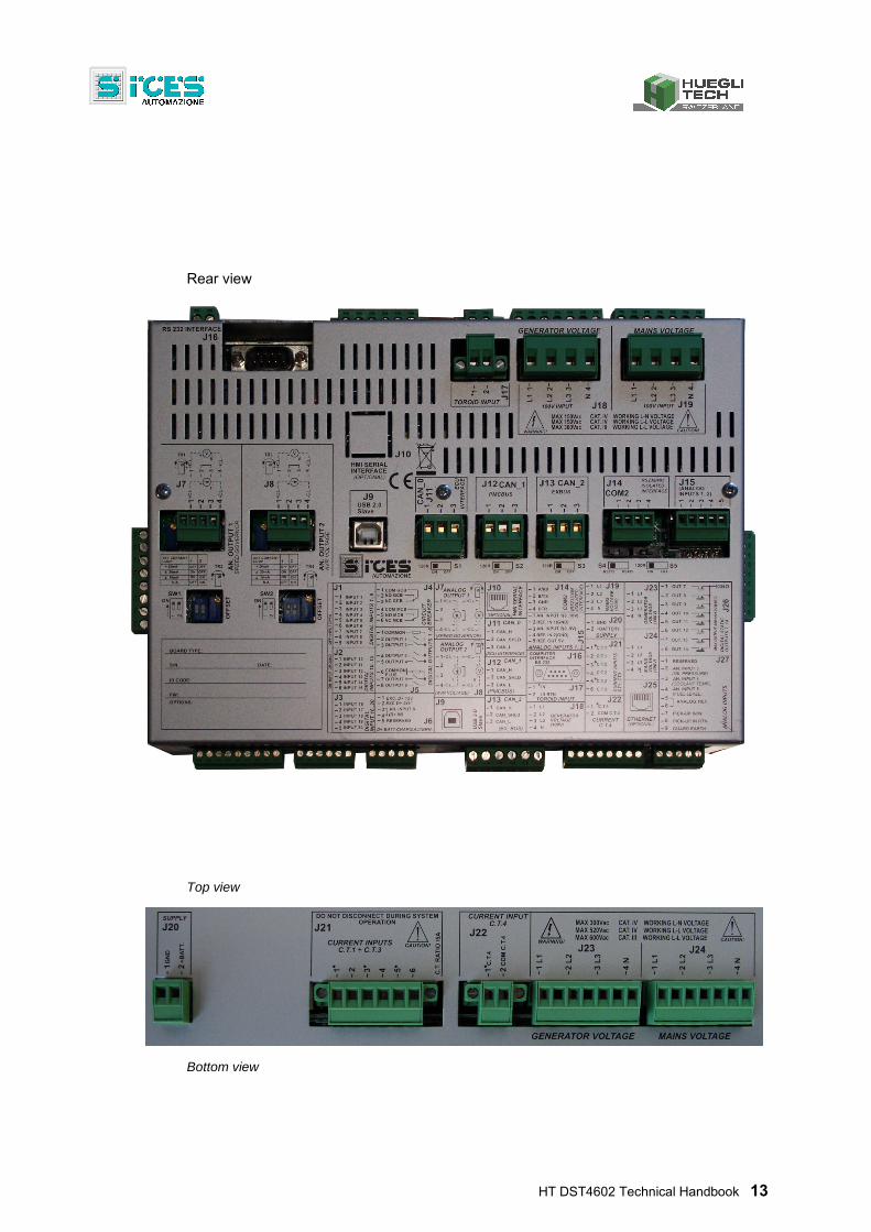
Rear view
Top view
Bottom view
14 HT DST4602 Technical Handbook
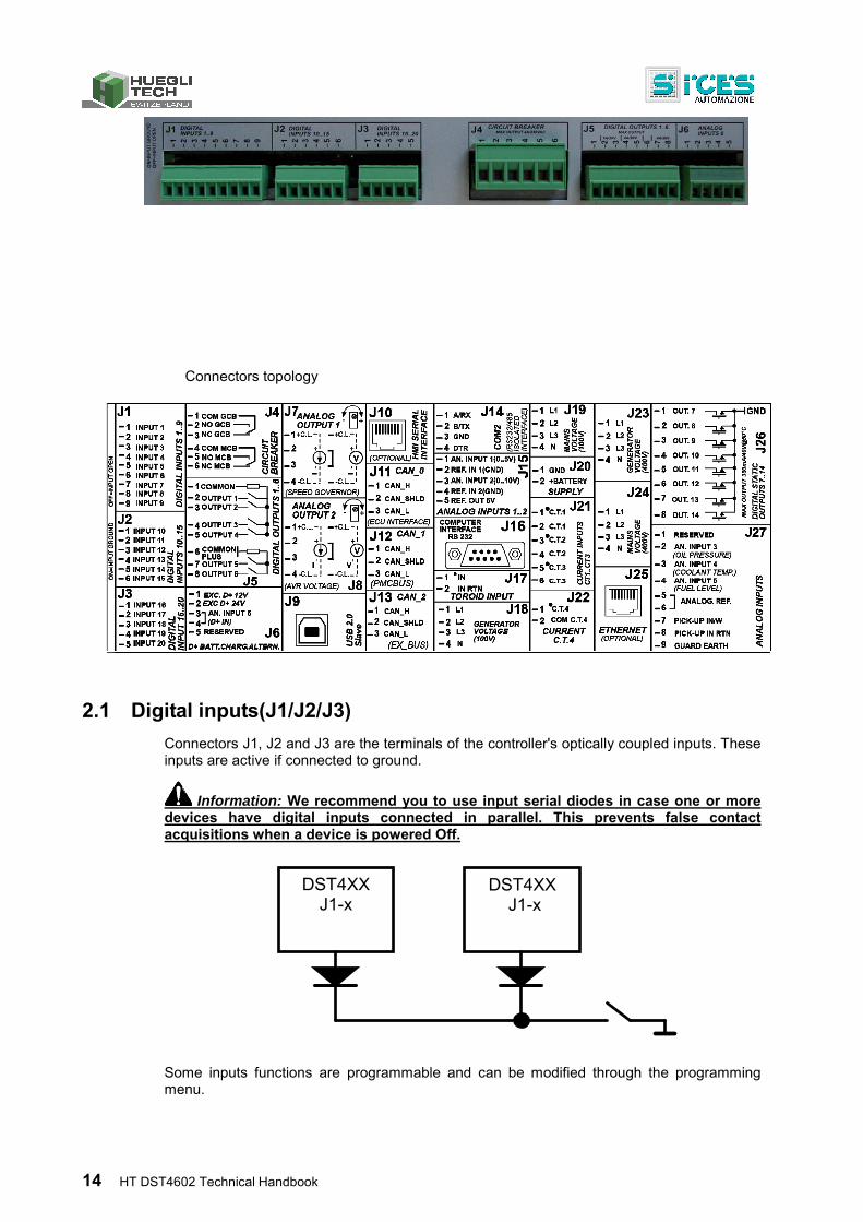
Connectors topology
2.1 Digital inputs(J1/J2/J3)
Connectors J1, J2 and J3 are the terminals of the controller's optically coupled inputs. These inputs are active if connected to ground.
Information: We recommend you to use input serial diodes in case one or more devices have digital inputs connected in parallel. This prevents false contact acquisitions when a device is powered Off.
Some inputs functions are programmable and can be modified through the programming menu.
DST4XX J1-x
DST4XX J1-x
HT DST4602 Technical Handbook 15
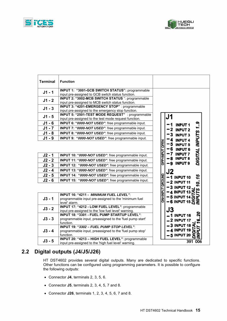
Terminal Function
J1 - 1 INPUT 1: “3001-GCB SWITCH STATUS”: programmable input pre-assigned to GCB switch status function.
J1 - 2 INPUT 2: “3002-MCB SWITCH STATUS “: programmable input pre-assigned to MCB switch status function.
J1 - 3 INPUT 3: “4201-EMERGENCY STOP” : programmable input pre-assigned to the emergency stop function.
J1 - 5 INPUT 5: “2501-TEST MODE REQUEST” : programmable input pre-assigned to the test mode request function.
J1 - 6 INPUT 6: “0000-NOT USED”: free programmable input.
J1 - 7 INPUT 7: “0000-NOT USED”: free programmable input.
J1 - 8 INPUT 8: “0000-NOT USED”: free programmable input.
J1 - 9 INPUT 9: “0000-NOT USED”: free programmable input.
J2 - 1 INPUT 10: “0000-NOT USED”: free programmable input.
J2 - 2 INPUT 11: “0000-NOT USED”: free programmable input.
J2 - 3 INPUT 12: “0000-NOT USED”: free programmable input.
J2 - 4 INPUT 13: “0000-NOT USED”: free programmable input.
J2 - 5 INPUT 14: “0000-NOT USED”: free programmable input.
J2 - 6 INPUT 15: “0000-NOT USED”: free programmable input.
J3 - 1 INPUT 16: “4211 - MINIMUM FUEL LEVEL”: programmable input pre-assigned to the 'minimum fuel level' alarm.
J3 - 2 INPUT 17: “4212 - LOW FUEL LEVEL”: programmable input pre-assigned to the 'low fuel level' warning.
J3 - 3 INPUT 18: “3301 - FUEL PUMP STARTUP LEVEL”: programmable input, preassigned to the 'fuel pump start' function.
J3 - 4 INPUT 19: “3302 – FUEL PUMP STOP LEVEL”: programmable input, preassigned to the 'fuel pump stop' function.
J3 - 5 INPUT 20: “4213 – HIGH FUEL LEVEL”: programmable input pre-assigned to the 'high fuel level' warning.
2.2 Digital outputs (J4/J5/J26)
HT DST4602 provides several digital outputs. Many are dedicated to specific functions. Other functions can be configured using programming parameters. It is possible to configure the following outputs:
Connector J4, terminals 2, 3, 5, 6.
Connector J5, terminals 2, 3, 4, 5, 7 and 8.
Connector J26, terminals 1, 2, 3, 4, 5, 6, 7 and 8.
16 HT DST4602 Technical Handbook
Connector J6, terminals 1 and 2
Therefore, up to twenty configurable outputs are available. Configurable outputs are used for:
Auxiliary engine commands.
Auxiliary generic commands.
Remote signalling of controller status.
Possible configurations are described below. A parameter is associated to each configurable output (i.e. P.0584 for output 21), that allows configuring the function. Two more parameters are available for each output (P.0601 and P.0602 for output 21); they are used to configure the output as remote status signalling, detailing the status the controller has to signal (see below). No configurable timings are associated to the outputs.
The following tables show all the possible functions (ordered by categories).
Codes to associate the output to engine auxiliary commands. See also 3.7.
Code Description
2 Glow-plugs preheating commands (Diesel engines).
14 Gas valve command (gas engines).
16 Engine stop command when energized.
23 Idle speed command
25 Engine enable command: this command is activated together with the fuel solenoid valve, but is disabled before it (time configurable with P.0234)
Codes to associate the output to generic auxiliary commands.
Code Description
1 Reset pulse. The controller generates a one-second pulse on this output when resetting the anomalies (key switched to OFF/RESET). NOTE: no pulse generated during the acknowledgment operation (ACK/TEST button). Refer also to chapter 4.
3 Fuel pump command (refer to paragraph 5.4).
4 Load management (refer to paragraph 5.11).
15 Monostable: generates an impulse of known length when an input is activated (see HT DST4602 parameters table).
21 External horn: the output is activated in parallel to the internal horn.
24 Coolant preheating. The controller can activate this output when the fluid temperature decreases below a settable threshold.
26 Enable synchronizer. This output is activated during the synchronization phase (both on MCB and GCB). It can be used to enable the external synchronizer, the synchronoscope, etc…
27 Enable load sharing unit. This output is activated during load sharing step (MPM o MPtM). It must to be used to enable the external load sharing unit, if PMCB bus is not used to run the sharing.
28 Select reverse synchronization. This output is activated during the synchronization phase (only on MCB). It can be used to switch voltage inputs on external synchronizer to synchronize both on MCB and GCB.
29 Disable MCB minimum voltage coil. When active, it disables the MCB minimum voltage coil, and then opens it. When not active, it allows the breaker to close.
30 Enable GCB minimum voltage coil. When not active, it disables the GCB minimum voltage coil, and then opens it. When active, it allows the breaker to close.
31 IGG closing command. Allows to close the breaker connecting the parallel bars to loads.
HT DST4602 Technical Handbook 17
32 IGG opening command. Allows to open the breaker connecting the parallel bars to loads.
33 Neutral breaker command. The controller automatically commands the neutral breaker in order to open it as soon as the gen-set is in parallel and to close it when not in parallel.
Codes to associate the output to remote status signalling functions.
Code Description
5 Signal for TEST in progress (refer to par. 3.1)..
6 Signal for mains measures in tolerance (refer to par. 3.3).
7 Signal for generator measures in tolerance
8 Signal for engine running.
9 Signal for (cumulative) generator anomalies: D01, A02, A06, A08, A15, A16, A52, A53, X55.
10 Signal for (cumulative) engine anomalies: A05, A21, A22, W31, W32, A33, A34, W37, W38, X39, A41, A42, W43, W44, A47, W49.
11 Signal for (cumulative) engine speed regulator anomalies: D03, A04, A11, A17, A18, A19.
12 Signal for (cumulative) fuel anomalies: A25, A26, W27, W28, W29, W30.
13 Signal for (cumulative) change-over anomalies: W13, W14, W23, W24.
17 Signal for (cumulative) anomalies classified as alarms and deactivations.
18 Signal for (cumulative) anomalies classified as warnings.
19 Key-lock switch in MAN or AUTO.
20 Key-lock in AUTO.
In addition to the a.m. codes, code 22 is provided for configuring the output for an internal status generic signal. 128 conditions are defined, that include all alarms and warnings (already implemented or future) and a series of status such as mains, generator, engine, change-over, key-lock switch, etc. One to 128 conditions can be associated to each output, which will be activated if at least one condition is met (OR logic). NOTE: an AND logic is also possible, by selecting all the conditions except the requested ones, and reversing the output status. The document [7] provides a table listing all possible conditions, numbered from 0 to 127. Not all conditions are assigned: some spare conditions are reserved for future requirements. In particular, conditions from 0 and 95 are reserved for alarms and warnings.
The conditions can be configured on the controller using the programming parameters. The 128 possible conditions are divided in two blocks of 64 each. Two parameters are provided for each output, allowing to set the two blocks of 64 bit (for output 21, parameters are P.0601 and P.0602). Each parameter allows to set the 64 bit status as a hexadecimal string (to represent 64 bit, 8 bytes and 16 hexadecimal characters are required). In the 16 hexadecimal digits, the last digit on the right is the less significant. Moreover, between the two parameters associated to each output, the one with lower index sets the conditions numbered from 0 to 63; the one with higher index sets the conditions from 64 to 127. For example: parameter P.0601 contains the string 0800000000000001 and parameter P.0602 the string 0100000400000000; these two parameters configure the output 21 (you must first set 22 in parameter P.0584). In the string in P.0601, bits 0 and 59 are active, which correspond to the conditions 0 (overcrank alarm) and 59 (maximum auxiliary current alarm). In the string P.0602, the bits 34 and 56 are active, which correspond to the conditions 64+34=98 (cumulative alarms) and 64+56=120 (engine running). The output 21 will activate if at least one of the four previous conditions is met (the example has no meaning; it is used only to show the relation between the parameters and the conditions for the outputs).
18 HT DST4602 Technical Handbook
Remember that a hexadecimal digit has values ranging from 0 and 9 and from A and F, for a total of 16 different values. Those 16 values originate from the combination of 4 bits; for this reason, 16 characters are required to express 64 bits. Therefore, to locate the position of a function in the string, given the number of the function, proceed as follows:
First digit on the right contains bits (functions) 0 to 3 or, if this is the highest parameter (i.e. P.0602), the functions 64 to 67.
For each digit shifting to the left, increase the counter of 4 until the digit containing the bit (desired function) is located.
Alternatively, divide by 4 the function number and start counting left to right till obtaining the division's result: remember that the first digit on the left has index 0.
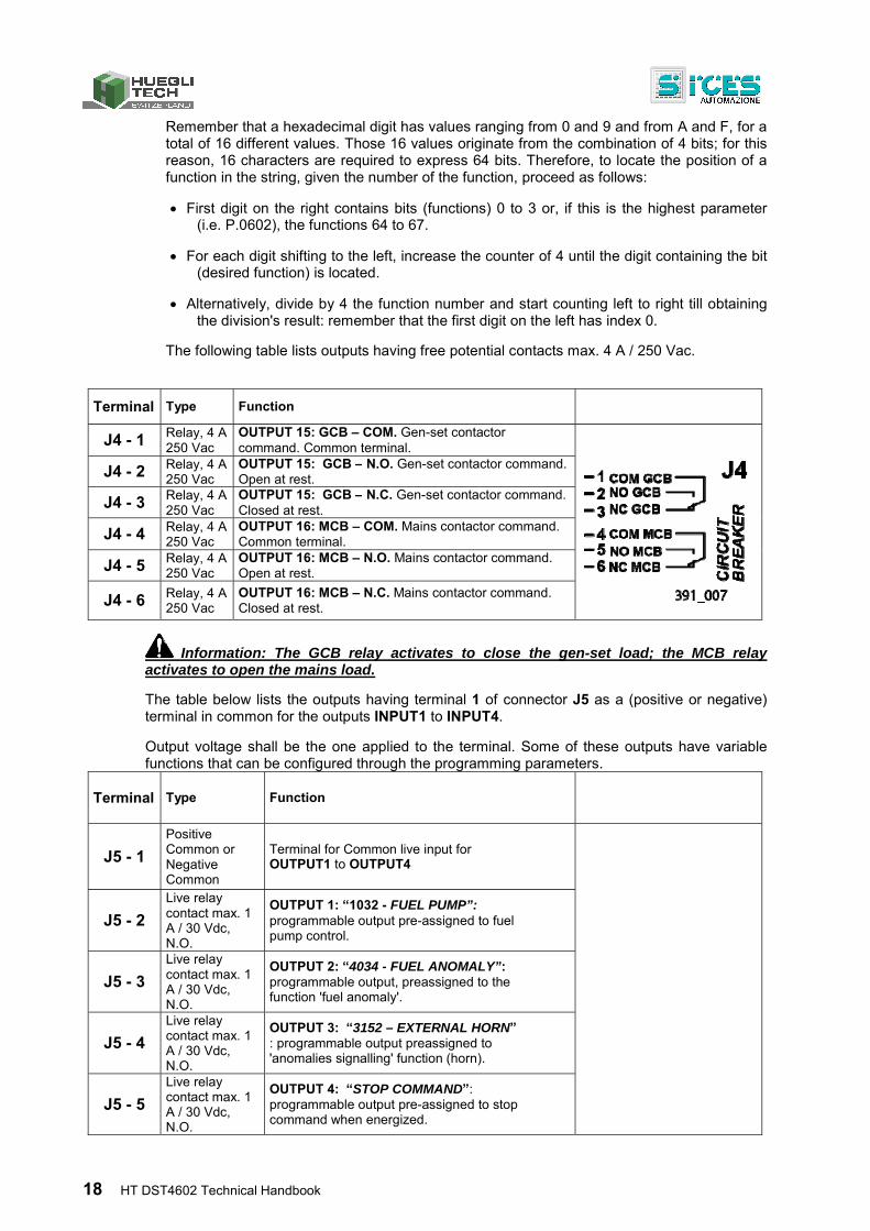
The following table lists outputs having free potential contacts max. 4 A / 250 Vac.
Terminal Type Function
J4 - 1 Relay, 4 A 250 Vac
OUTPUT 15: GCB – COM. Gen-set contactor command. Common terminal.
J4 - 2 Relay, 4 A 250 Vac
OUTPUT 15: GCB – N.O. Gen-set contactor command. Open at rest.
J4 - 3 Relay, 4 A 250 Vac
OUTPUT 15: GCB – N.C. Gen-set contactor command. Closed at rest.
J4 - 4 Relay, 4 A 250 Vac
OUTPUT 16: MCB – COM. Mains contactor command. Common terminal.
J4 - 5 Relay, 4 A 250 Vac
OUTPUT 16: MCB – N.O. Mains contactor command. Open at rest.
J4 - 6 Relay, 4 A 250 Vac
OUTPUT 16: MCB – N.C. Mains contactor command. Closed at rest.
Information: The GCB relay activates to close the gen-set load; the MCB relay activates to open the mains load.
The table below lists the outputs having terminal 1 of connector J5 as a (positive or negative) terminal in common for the outputs INPUT1 to INPUT4.
Output voltage shall be the one applied to the terminal. Some of these outputs have variable functions that can be configured through the programming parameters.
Terminal Type Function
J5 - 1
Positive Common or Negative Common
Terminal for Common live input for OUTPUT1 to OUTPUT4
J5 - 2
Live relay contact max. 1 A / 30 Vdc, N.O.
OUTPUT 1: “1032 - FUEL PUMP”: programmable output pre-assigned to fuel pump control.
J5 - 3
Live relay contact max. 1 A / 30 Vdc, N.O.
OUTPUT 2: “4034 - FUEL ANOMALY”: programmable output, preassigned to the function 'fuel anomaly'.
J5 - 4
Live relay contact max. 1 A / 30 Vdc, N.O.
OUTPUT 3: “3152 – EXTERNAL HORN” : programmable output preassigned to 'anomalies signalling' function (horn).
J5 - 5
Live relay contact max. 1 A / 30 Vdc, N.O.
OUTPUT 4: “STOP COMMAND”: programmable output pre-assigned to stop command when energized.
HT DST4602 Technical Handbook 19
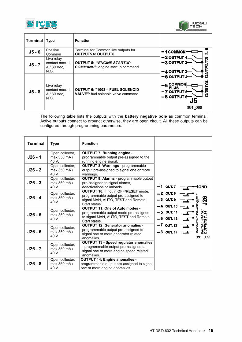
Terminal Type Function
J5 - 6 Positive Common
Terminal for Common live outputs for OUTPUT5 to OUTPUT6
J5 - 7
Live relay contact max. 1 A / 30 Vdc, N.O.
OUTPUT 5: “ENGINE STARTUP COMMAND”: engine startup command.
J5 - 8
Live relay contact max. 1 A / 30 Vdc, N.O.
OUTPUT 6: “1003 – FUEL SOLENOID VALVE”: fuel solenoid valve command.
The following table lists the outputs with the battery negative pole as common terminal. Active outputs connect to ground; otherwise, they are open circuit. All these outputs can be configured through programming parameters.
Terminal Type Function
J26 - 1 Open collector, max 350 mA / 40 V.
OUTPUT 7: Running engine -programmable output pre-assigned to the running engine signal.
J26 - 2 Open collector, max 350 mA / 40 V
OUTPUT 8: Warnings - programmable output pre-assigned to signal one or more warnings.
J26 - 3 Open collector, max 350 mA / 40 V
OUTPUT 9: Alarms - programmable output pre-assigned to signal alarms, deactivations or unloads.
J26 - 4 Open collector, max 350 mA / 40 V
OUTPUT 10: If not in OFF/RESET mode, programmable output pre-assigned to signal MAN, AUTO, TEST and Remote Start status.
J26 - 5 Open collector, max 350 mA / 40 V
OUTPUT 11: One of Auto modes - programmable output mode pre-assigned to signal MAN, AUTO, TEST and Remote Start status.
J26 - 6 Open collector, max 350 mA / 40 V
OUTPUT 12: Generator anomalies - programmable output pre-assigned to signal one or more generator related anomalies.
J26 - 7 Open collector, max 350 mA / 40 V
OUTPUT 13 - Speed regulator anomalies - programmable output pre-assigned to signal one or more engine speed related anomalies.
J26 - 8 Open collector, max 350 mA / 40 V
OUTPUT 14: Engine anomalies - programmable output pre-assigned to signal one or more engine anomalies.
20 HT DST4602 Technical Handbook
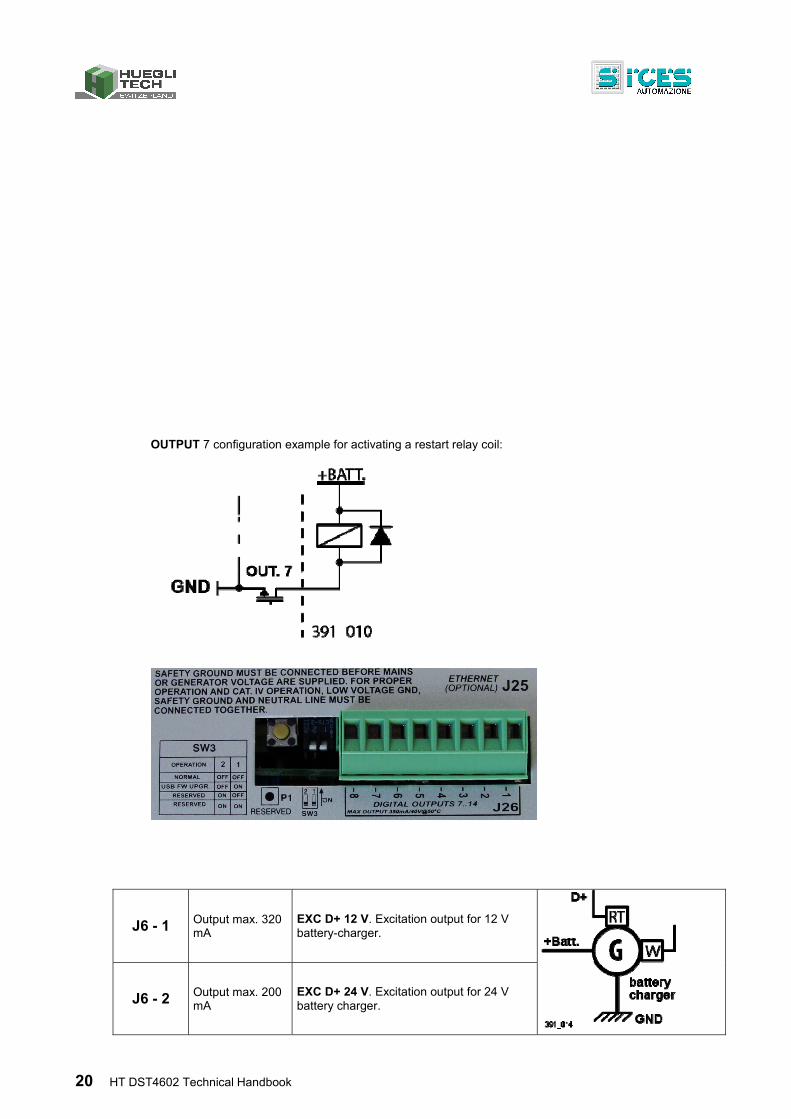
OUTPUT 7 configuration example for activating a restart relay coil:
J6 - 1 Output max. 320 mA
EXC D+ 12 V. Excitation output for 12 V battery-charger.
J6 - 2 Output max. 200 mA
EXC D+ 24 V. Excitation output for 24 V battery charger.
HT DST4602 Technical Handbook 21
2.3 Measure inputs
2.3.1 Currents input (J17/J21/J22)
Terminal Type Function
J21 - 1 AT(amperometric transformer) XXX/max. 5 A
Input CT1 (S1) 'hot' pole
J21 - 2 Input CT1 (S2) 'cold' pole
J21 - 3 AT(amperometric transformer) XXX/max. 5 A
Input CT2 (S1) 'hot' pole
J21 - 4 Input CT2 (S2) 'cold' pole
J21 - 5 AT(amperometric transformer) XXX/max. 5 A
Input CT3 (S1) 'hot' pole
J21 - 6 Input CT3 (S2) 'cold' pole
The controller is equipped with a J17 or J22 input for measuring auxiliary currents.
For the controller to acquire the J17 input measure (Toroid), the installed option (with parameter P.0109 Transformer type for auxiliary power) must be set:
In case an AT(amperometric transformer) is used, ensure to set 0 in parameter P.0109, the AT primary in parameter P.0108 and the secondary in parameter P.0140.
In case a Toroid is used, ensure to set 1 in parameter P.0109, the primary dimming ratio in parameter P.0108 and the secondary dimming ratio in parameter P.0140.
According to the configuration, ensure to set also the auxiliary current reading parameters:
P.0130 Auxiliary current connection. Set the values that define where the AT or the Toroid are installed (0=Generator, 1=Loads, 2= Mains).
P.0131 Auxiliary current use. Set the values that define the used measure (0=not used, 1= general usage, 2=neutral on generator, 3=differential protection, 4=mains power measure ).
Parameter P.0132 (correction for calculating power on the mains), allows to enter a correction value; up to three decimals can be entered. This value is only used in case parameter P.0131 is set to 4.
After completing the configuration, the measure is shown in page M.01 and/or M.06 of the display. By using parameters P.0367 and P.0368 it is possible to enable a protection in case a threshold value (A45) is exceeded.
Important! In case parameter P.0131, power on mains measure =4, in order to correctly measure the power ensure to set the AT on phase L1 .
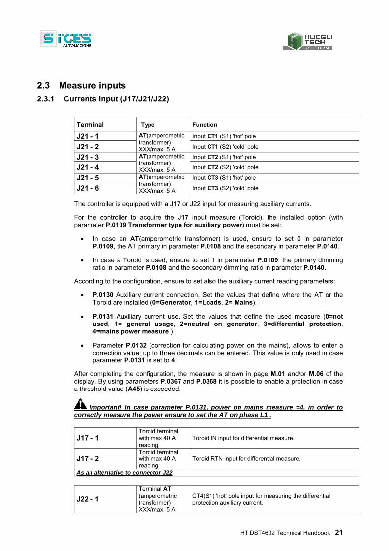
J17 - 1 Toroid terminal with max 40 A reading
Toroid IN input for differential measure.
J17 - 2 Toroid terminal with max 40 A reading
Toroid RTN input for differential measure.
As an alternative to connector J22
J22 - 1
Terminal AT (amperometric transformer) XXX/max. 5 A
CT4(S1) 'hot' pole input for measuring the differential protection auxiliary current.
22 HT DST4602 Technical Handbook
J22 - 2
Terminal AT (amperometric transformer) XXX/max. 5 A
CT4(S2) 'cold' pole input for measuring the differential protection auxiliary current.
Alternative to connector J17
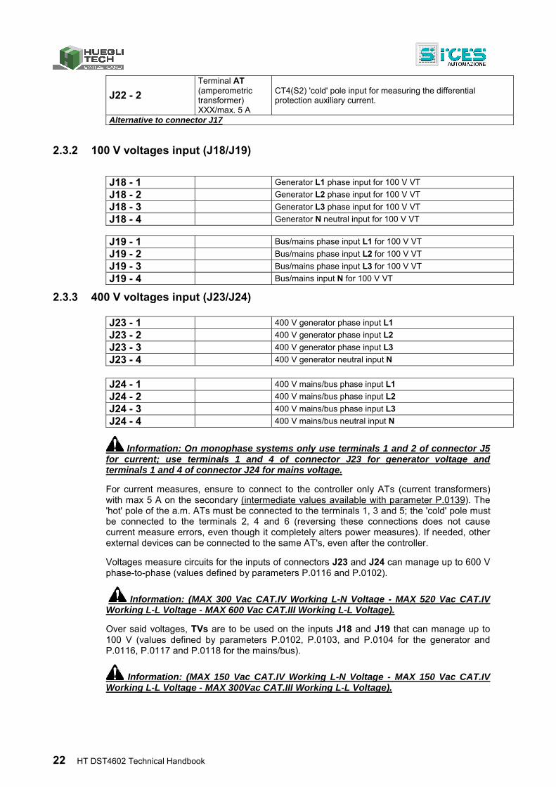
2.3.2 100 V voltages input (J18/J19)
J18 - 1 Generator L1 phase input for 100 V VT
J18 - 2 Generator L2 phase input for 100 V VT
J18 - 3 Generator L3 phase input for 100 V VT
J18 - 4 Generator N neutral input for 100 V VT
J19 - 1 Bus/mains phase input L1 for 100 V VT
J19 - 2 Bus/mains phase input L2 for 100 V VT
J19 - 3 Bus/mains phase input L3 for 100 V VT
J19 - 4 Bus/mains input N for 100 V VT
2.3.3 400 V voltages input (J23/J24)
J23 - 1 400 V generator phase input L1
J23 - 2 400 V generator phase input L2
J23 - 3 400 V generator phase input L3
J23 - 4 400 V generator neutral input N
J24 - 1 400 V mains/bus phase input L1
J24 - 2 400 V mains/bus phase input L2
J24 - 3 400 V mains/bus phase input L3
J24 - 4 400 V mains/bus neutral input N
Information: On monophase systems only use terminals 1 and 2 of connector J5 for current; use terminals 1 and 4 of connector J23 for generator voltage and terminals 1 and 4 of connector J24 for mains voltage.
For current measures, ensure to connect to the controller only ATs (current transformers) with max 5 A on the secondary (intermediate values available with parameter P.0139). The 'hot' pole of the a.m. ATs must be connected to the terminals 1, 3 and 5; the 'cold' pole must be connected to the terminals 2, 4 and 6 (reversing these connections does not cause current measure errors, even though it completely alters power measures). If needed, other external devices can be connected to the same AT's, even after the controller.
Voltages measure circuits for the inputs of connectors J23 and J24 can manage up to 600 V phase-to-phase (values defined by parameters P.0116 and P.0102).
Information: (MAX 300 Vac CAT.IV Working L-N Voltage - MAX 520 Vac CAT.IV Working L-L Voltage - MAX 600 Vac CAT.III Working L-L Voltage).
Over said voltages, TVs are to be used on the inputs J18 and J19 that can manage up to 100 V (values defined by parameters P.0102, P.0103, and P.0104 for the generator and P.0116, P.0117 and P.0118 for the mains/bus).
Information: (MAX 150 Vac CAT.IV Working L-N Voltage - MAX 150 Vac CAT.IV Working L-L Voltage - MAX 300Vac CAT.III Working L-L Voltage).
HT DST4602 Technical Handbook 23
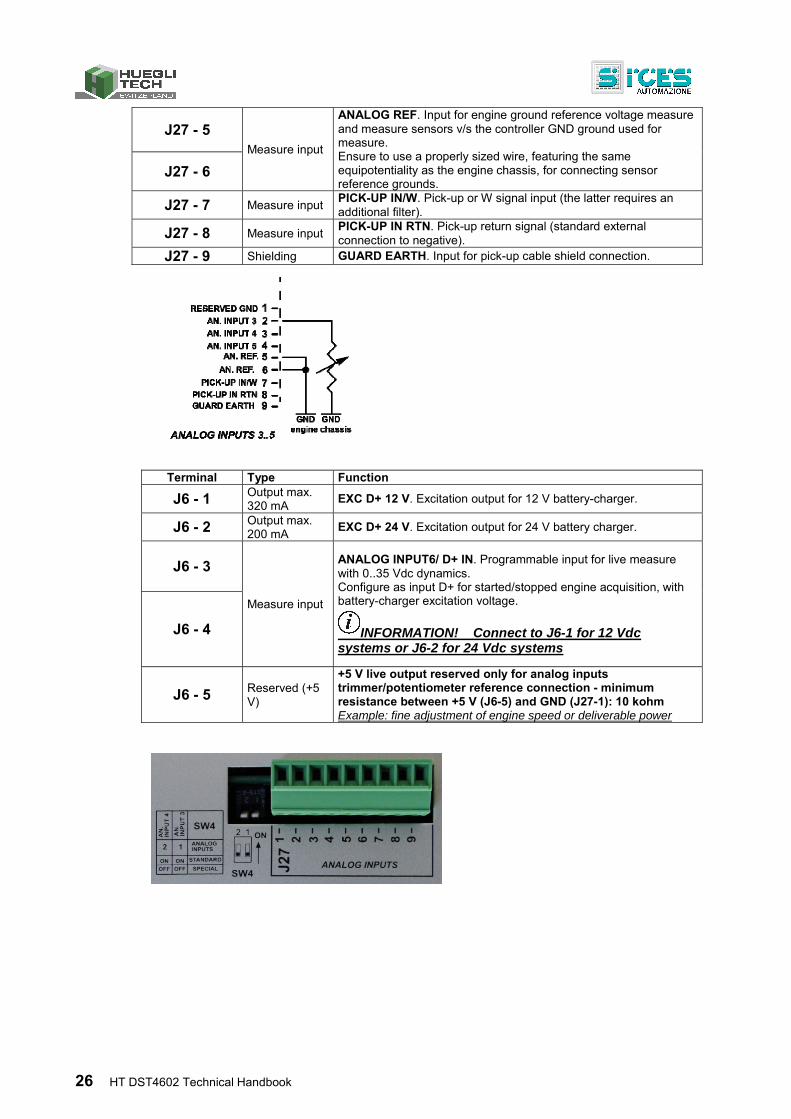
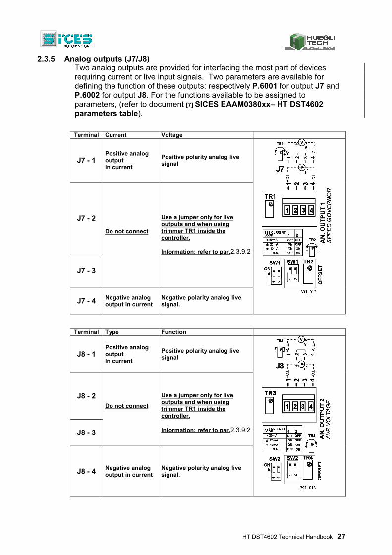
2.3.4 Analog inputs (J6/J15/J27)
All analog inputs can be configured for several measure requirements. These configurations can be either hardware or software.
Hardware configurations can be voltage or resistive measures:
1. Live inputs are “ANALOG INPUT 1”, “ANALOG INPUT 2” and, when not used for D+, also “ANALOG INPUT 6”. Ground references for inputs “ANALOG INPUT 1” and “ANALOG INPUT 2” are respectively Pin 2 and 4 of J15.
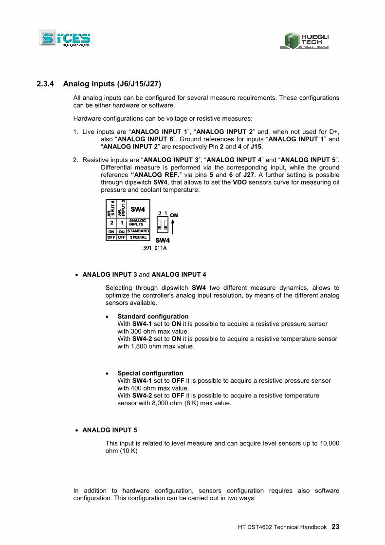
2. Resistive inputs are “ANALOG INPUT 3”, “ANALOG INPUT 4” and “ANALOG INPUT 5”. Differential measure is performed via the corresponding input, while the ground reference “ANALOG REF.” via pins 5 and 6 of J27. A further setting is possible through dipswitch SW4, that allows to set the VDO sensors curve for measuring oil pressure and coolant temperature:
ANALOG INPUT 3 and ANALOG INPUT 4
Selecting through dipswitch SW4 two different measure dynamics, allows to optimize the controller's analog input resolution, by means of the different analog sensors available.
Standard configuration With SW4-1 set to ON it is possible to acquire a resistive pressure sensor with 300 ohm max value. With SW4-2 set to ON it is possible to acquire a resistive temperature sensor with 1,800 ohm max value.
Special configuration With SW4-1 set to OFF it is possible to acquire a resistive pressure sensor with 400 ohm max value. With SW4-2 set to OFF it is possible to acquire a resistive temperature sensor with 8,000 ohm (8 K) max value.
ANALOG INPUT 5
This input is related to level measure and can acquire level sensors up to 10,000 ohm (10 K)
In addition to hardware configuration, sensors configuration requires also software configuration. This configuration can be carried out in two ways:
24 HT DST4602 Technical Handbook
Configuration via panel:
Configuration carried out for VDO sensors, generic sensor or as digital input.
Configuration via operator's panel is limited, as only some sensor curves are stored in the controller; thus, it is not possible to create a measure curve via the operator's panel.
Configuration on PC via software:
In order to configure sensors featuring different curves, you need a PC with the software “controller PRG 3 ver.3.0” and/or higher, and a connection interface to the controller HT DST4602. For these types of connection refer to the document [4] SICES EAAS0341xx– Serial communication.
The software section "I/O”, at the sub-menu "analog inputs”, contains all the sensor's manufacturer guidelines that allow to configure the different measure curves, the required decimal digits and the resolution points.
After creating the sensor, it can be saved for future usage and then transmitted to the controller.
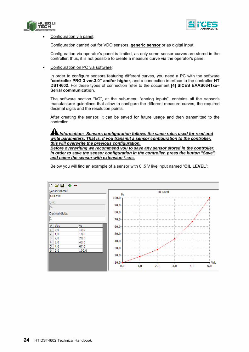
Information: Sensors configuration follows the same rules used for read and write parameters. That is, if you transmit a sensor configuration to the controller, this will overwrite the previous configuration. Before overwriting we recommend you to save any sensor stored in the controller. In order to save the sensor configuration in the controller, press the button "Save” and name the sensor with extension *.sns.
Below you will find an example of a sensor with 0..5 V live input named “OIL LEVEL”:
HT DST4602 Technical Handbook 25
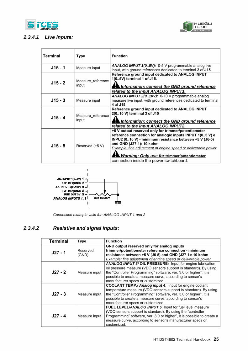
2.3.4.1 Live inputs:
Terminal Type Function
J15 - 1 Measure input ANALOG INPUT 1(0..5V): 0-5 V programmable analog live input, with ground references dedicated to terminal 2 of J15.
J15 - 2 Measure_reference input
Reference ground input dedicated to ANALOG INPUT 1(0..5V) terminal 1 of J15.
Information: connect the GND ground reference related to the input ANALOG INPUT1.
J15 - 3 Measure input ANALOG INPUT 2(0..10V): 0-10 V programmable analog measure live input, with ground references dedicated to terminal 4 of J15.
J15 - 4 Measure_reference input
Reference ground input dedicated to ANALOG INPUT 2(0..10 V) terminal 3 of J15
Information: connect the GND ground reference related to the input ANALOG INPUT2.
J15 - 5 Reserved (+5 V)
+5 V output reserved only for trimmer/potentiometer reference connection for analogic inputs INPUT 1(0..5 V) e INPU2 (0..10 V) - minimum resistance between +5 V (J6-5) and GND (J27-1): 10 kohm Example: fine adjustment of engine speed or deliverable power
Warning: Only use for trimmer/potentiometer connection inside the power switchboard.
Connection example valid for: ANALOG INPUT 1 and 2
2.3.4.2 Resistive and signal inputs:
Terminal Type Function
J27 - 1 Reserved (GND)
GND output reserved only for analog inputs trimmer/potentiometer reference connection - minimum resistance between +5 V (J6-5) and GND (J27-1): 10 kohm Example: fine adjustment of engine speed or deliverable power
J27 - 2 Measure input
ANALOG INPUT 3/ OIL PRESSURE: Input for engine lubrication oil pressure measure (VDO sensors support is standard). By using the “Controller Programming” software, ver. 3.0 or higher”, it is possible to create a measure curve, according to sensor's manufacturer specs or customized.
J27 - 3 Measure input
COOLANT TEMP./ Analog input 4. Input for engine coolant temperature measure (VDO sensors support is standard). By using the “Controller Programming” software, ver. 3.0 or higher”, it is possible to create a measure curve, according to sensor's manufacturer specs or customized.
J27 - 4 Measure input
FUEL LEVEL/ANALOG INPUT 5. Input for fuel level measure (VDO sensors support is standard). By using the “controller Programming” software, ver. 3.0 or higher”, it is possible to create a measure curve, according to sensor's manufacturer specs or customized.
26 HT DST4602 Technical Handbook
J27 - 5
Measure input
ANALOG REF. Input for engine ground reference voltage measure and measure sensors v/s the controller GND ground used for measure. Ensure to use a properly sized wire, featuring the same equipotentiality as the engine chassis, for connecting sensor reference grounds.
J27 - 6
J27 - 7 Measure input PICK-UP IN/W. Pick-up or W signal input (the latter requires an additional filter).
J27 - 8 Measure input PICK-UP IN RTN. Pick-up return signal (standard external connection to negative).
J27 - 9 Shielding GUARD EARTH. Input for pick-up cable shield connection.
Terminal Type Function
J6 - 1 Output max. 320 mA
EXC D+ 12 V. Excitation output for 12 V battery-charger.
J6 - 2 Output max. 200 mA
EXC D+ 24 V. Excitation output for 24 V battery charger.
J6 - 3
Measure input
ANALOG INPUT6/ D+ IN. Programmable input for live measure with 0..35 Vdc dynamics. Configure as input D+ for started/stopped engine acquisition, with battery-charger excitation voltage.
INFORMATION! Connect to J6-1 for 12 Vdc systems or J6-2 for 24 Vdc systems
J6 - 4
J6 - 5 Reserved (+5 V)
+5 V live output reserved only for analog inputs trimmer/potentiometer reference connection - minimum resistance between +5 V (J6-5) and GND (J27-1): 10 kohm Example: fine adjustment of engine speed or deliverable power
HT DST4602 Technical Handbook 27
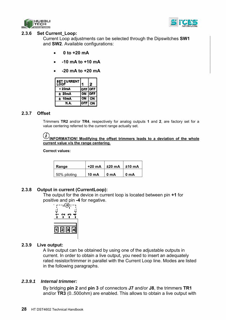
2.3.5 Analog outputs (J7/J8) Two analog outputs are provided for interfacing the most part of devices requiring current or live input signals. Two parameters are available for defining the function of these outputs: respectively P.6001 for output J7 and P.6002 for output J8. For the functions available to be assigned to parameters, (refer to document [7] SICES EAAM0380xx– HT DST4602 parameters table).
Terminal Current Voltage
J7 - 1 Positive analog output In current
Positive polarity analog live signal
J7 - 2
Do not connect
Use a jumper only for live outputs and when using trimmer TR1 inside the controller. Information: refer to par.2.3.9.2
J7 - 3
J7 - 4 Negative analog output in current
Negative polarity analog live signal.
Terminal Type Function
J8 - 1 Positive analog output In current
Positive polarity analog live signal
J8 - 2
Do not connect
Use a jumper only for live outputs and when using trimmer TR1 inside the controller. Information: refer to par.2.3.9.2J8 - 3
J8 - 4 Negative analog output in current
Negative polarity analog live signal.
28 HT DST4602 Technical Handbook
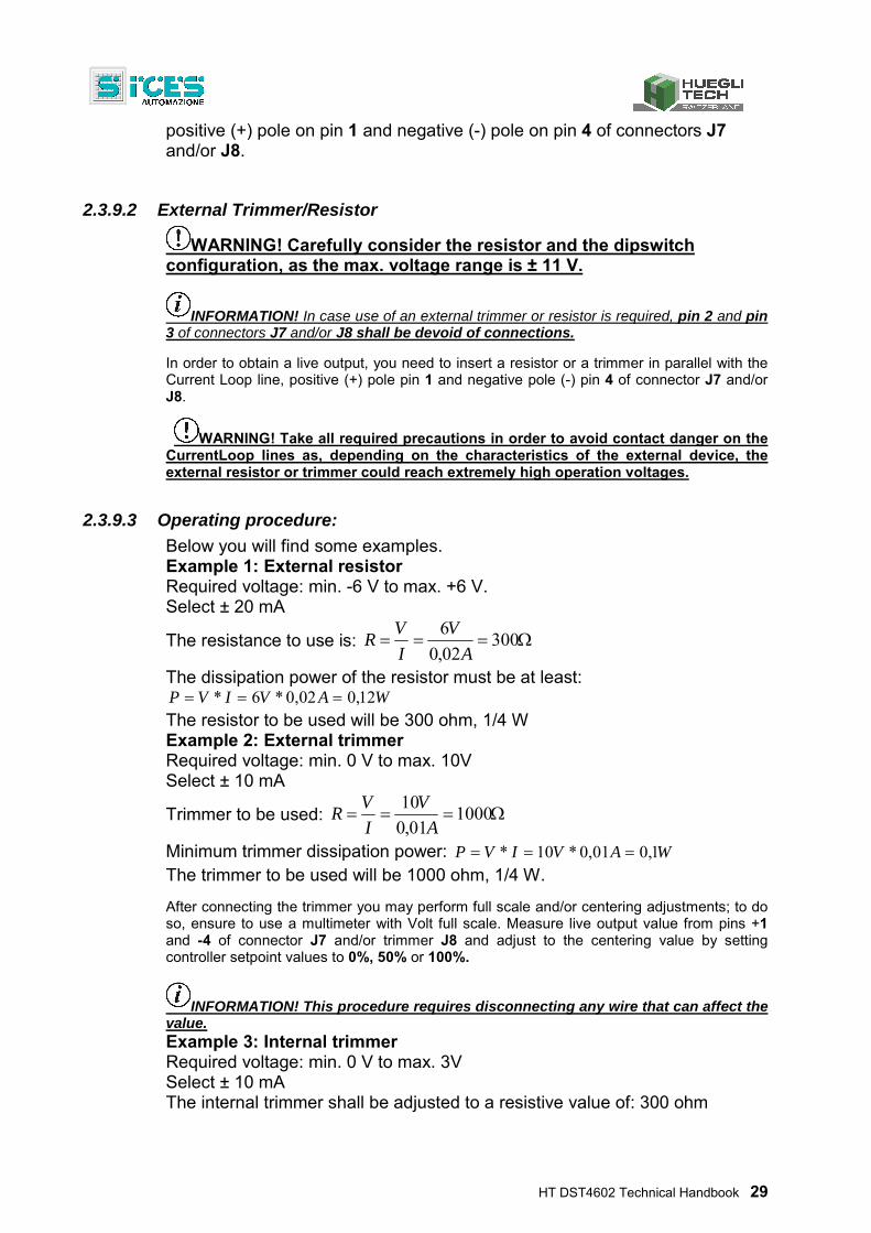
2.3.6 Set Current_Loop: Current Loop adjustments can be selected through the Dipswitches SW1 and SW2. Available configurations:
0 to +20 mA
-10 mA to +10 mA
-20 mA to +20 mA
2.3.7 Offset
Trimmers TR2 and/or TR4, respectively for analog outputs 1 and 2, are factory set for a value centering referred to the current range actually set.
INFORMATION! Modifying the offset trimmers leads to a deviation of the whole current value v/s the range centering.
Correct values:
Range +20 mA ±20 mA ±10 mA
50% piloting 10 mA 0 mA 0 mA
2.3.8 Output in current (CurrentLoop): The output for the device in current loop is located between pin +1 for positive and pin -4 for negative.
2.3.9 Live output: A live output can be obtained by using one of the adjustable outputs in current. In order to obtain a live output, you need to insert an adequately rated resistor/trimmer in parallel with the Current Loop line. Modes are listed in the following paragraphs.
2.3.9.1 Internal trimmer:
By bridging pin 2 and pin 3 of connectors J7 and/or J8, the trimmers TR1 and/or TR3 (0..500ohm) are enabled. This allows to obtain a live output with
HT DST4602 Technical Handbook 29
positive (+) pole on pin 1 and negative (-) pole on pin 4 of connectors J7 and/or J8.
2.3.9.2 External Trimmer/Resistor
WARNING! Carefully consider the resistor and the dipswitch configuration, as the max. voltage range is ± 11 V.
INFORMATION! In case use of an external trimmer or resistor is required, pin 2 and pin 3 of connectors J7 and/or J8 shall be devoid of connections.
In order to obtain a live output, you need to insert a resistor or a trimmer in parallel with the Current Loop line, positive (+) pole pin 1 and negative pole (-) pin 4 of connector J7 and/or J8.
WARNING! Take all required precautions in order to avoid contact danger on the CurrentLoop lines as, depending on the characteristics of the external device, the external resistor or trimmer could reach extremely high operation voltages.
2.3.9.3 Operating procedure:
Below you will find some examples. Example 1: External resistor Required voltage: min. -6 V to max. +6 V. Select ± 20 mA
The resistance to use is: 30002,0
6
A
V
I
VR
The dissipation power of the resistor must be at least: WAVIVP 12,002,0*6*
The resistor to be used will be 300 ohm, 1/4 W Example 2: External trimmer Required voltage: min. 0 V to max. 10V Select ± 10 mA
Trimmer to be used: 100001,0
10
A
V
I
VR
Minimum trimmer dissipation power: WAVIVP 1,001,0*10* The trimmer to be used will be 1000 ohm, 1/4 W.
After connecting the trimmer you may perform full scale and/or centering adjustments; to do so, ensure to use a multimeter with Volt full scale. Measure live output value from pins +1 and -4 of connector J7 and/or trimmer J8 and adjust to the centering value by setting controller setpoint values to 0%, 50% or 100%.
INFORMATION! This procedure requires disconnecting any wire that can affect the value. Example 3: Internal trimmer Required voltage: min. 0 V to max. 3V Select ± 10 mA The internal trimmer shall be adjusted to a resistive value of: 300 ohm

30 HT DST4602 Technical Handbook
In order to calibrate the trimmer, you must disconnect any wire and/or device that might affect the reading; using a multimeter with full scale in ohm between the pins 1 and 2 of J7 and/or J8, turn the adjustment screw till reading about 300 ohm.
In order to verify the full scale range adjustment and the centering value, use a multimeter with full scale in Volt on pins +1 and -4 of connector J7 and/or J8. With different controller setpoint values set to 0%, 50% or 100% it is possible to adjust the setpoint centering through the trimmer TR2 and/or TR4.
INFORMATION! This procedure requires disconnecting any wire that can affect the value.
HT DST4602 Technical Handbook 31
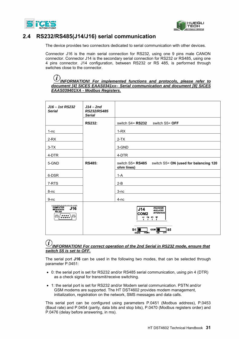
2.4 RS232/RS485(J14/J16) serial communication
The device provides two connectors dedicated to serial communication with other devices.
Connector J16 is the main serial connection for RS232, using one 9 pins male CANON connector. Connector J14 is the secondary serial connection for RS232 or RS485, using one 4 pins connector. J14 configuration, between RS232 or RS 485, is performed through switches close to the connector.
INFORMATION! For implemented functions and protocols, please refer to document [4] SICES EAAS0341xx– Serial communication and document [8] SICES EAAS039401XA - Modbus Registers.
J16 – 1st RS232 Serial
J14 – 2nd RS232/RS485 Serial
RS232: switch S4= RS232 switch S5= OFF
1-nc 1-RX
2-RX 2-TX
3-TX 3-GND
4-DTR 4-DTR
5-GND RS485: switch S5= RS485 switch S5= ON (used for balancing 120 ohm lines)
6-DSR 1-A
7-RTS 2-B
8-nc 3-nc
9-nc 4-nc
INFORMATION! For correct operation of the 2nd Serial in RS232 mode, ensure that switch S5 is set to OFF.
The serial port J16 can be used in the following two modes, that can be selected through parameter P.0451:
0: the serial port is set for RS232 and/or RS485 serial communication, using pin 4 (DTR) as a check signal for transmit/receive switching.
1: the serial port is set for RS232 and/or Modem serial communication. PSTN and/or GSM modems are supported. The HT DST4602 provides modem management, initialization, registration on the network, SMS messages and data calls.
This serial port can be configured using parameters P.0451 (Modbus address), P.0453 (Baud rate) and P.0454 (parity, data bits and stop bits), P.0470 (Modbus registers order) and P.0476 (delay before answering, in ms).
32 HT DST4602 Technical Handbook
The serial port J14 can be used only in one mode, that can be selected through parameter P.0471:
0: the second serial port works exactly as the first one (refer to document [4]). Exception: it’s not possible to connect a modem to the second serial port.
This serial port can be configured using parameters P.0472 (Modbus address), P.0473 (Baud rate) and P.0474 (parity, data bits and stop bits), P.0475 (Modbus registers order) and P.0477 (delay before answering, in ms).
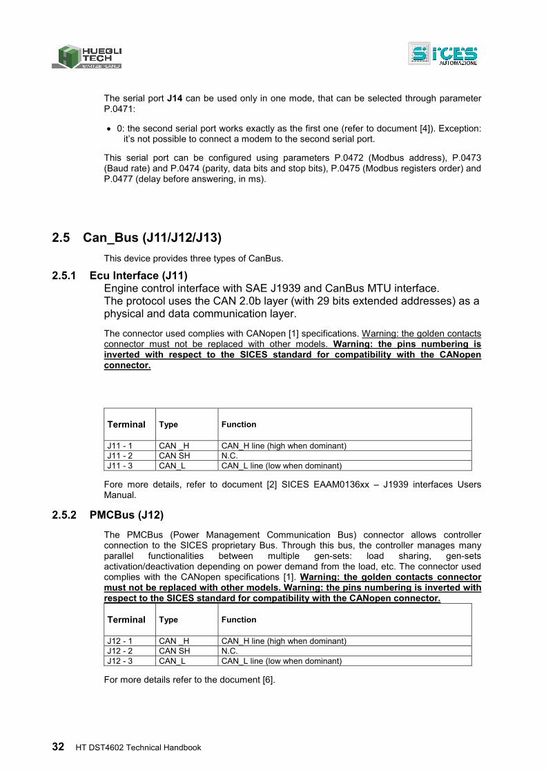
2.5 Can_Bus (J11/J12/J13)
This device provides three types of CanBus.
2.5.1 Ecu Interface (J11) Engine control interface with SAE J1939 and CanBus MTU interface. The protocol uses the CAN 2.0b layer (with 29 bits extended addresses) as a physical and data communication layer.
The connector used complies with CANopen [1] specifications. Warning: the golden contacts connector must not be replaced with other models. Warning: the pins numbering is inverted with respect to the SICES standard for compatibility with the CANopen connector.
Terminal Type Function
J11 - 1 CAN _H CAN_H line (high when dominant) J11 - 2 CAN SH N.C. J11 - 3 CAN_L CAN_L line (low when dominant)
Fore more details, refer to document [2] SICES EAAM0136xx – J1939 interfaces Users Manual.
2.5.2 PMCBus (J12)
The PMCBus (Power Management Communication Bus) connector allows controller connection to the SICES proprietary Bus. Through this bus, the controller manages many parallel functionalities between multiple gen-sets: load sharing, gen-sets activation/deactivation depending on power demand from the load, etc. The connector used complies with the CANopen specifications [1]. Warning: the golden contacts connector must not be replaced with other models. Warning: the pins numbering is inverted with respect to the SICES standard for compatibility with the CANopen connector.
Terminal Type Function
J12 - 1 CAN _H CAN_H line (high when dominant) J12 - 2 CAN SH N.C. J12 - 3 CAN_L CAN_L line (low when dominant)
For more details refer to the document [6].
HT DST4602 Technical Handbook 33
2.5.3 EX_BUS (J13)
The connector EX_BUS (Expansion Bus) allows to connect to HT DST4602 all the expansion modules using the SICES EX_BUS proprietary protocol. The modules DITEL, DITEMP(DIRES/DITHERM), DIVIT and DANOUT are presently supported.
The connector used complies with CANopen [1] specifications. Warning: the golden contacts connector must not be replaced with other models.
Terminal Type Function
J13 - 1 CAN _H CAN_H line (high when dominant) J13 - 2 CAN SH N.C. J13 - 3 CAN_L CAN_L line (low when dominant)
The interface is galvanically isolated. Therefore, power lines connection is required. For more details refer to the document [6].
2.6 Other connectors
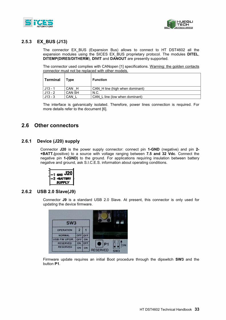
2.6.1 Device (J20) supply
Connector J20 is the power supply connector: connect pin 1-GND (negative) and pin 2-+BATT.(positive) to a source with voltage ranging between 7.5 and 32 Vdc. Connect the negative pin 1-(GND) to the ground. For applications requiring insulation between battery negative and ground, ask S.I.C.E.S. information about operating conditions.
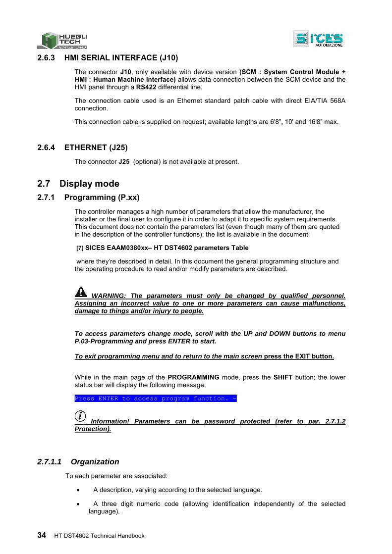
2.6.2 USB 2.0 Slave(J9)
Connector J9 is a standard USB 2.0 Slave. At present, this connector is only used for updating the device firmware.
Firmware update requires an initial Boot procedure through the dipswitch SW3 and the button P1.
34 HT DST4602 Technical Handbook
2.6.3 HMI SERIAL INTERFACE (J10)
The connector J10, only available with device version (SCM : System Control Module + HMI : Human Machine Interface) allows data connection between the SCM device and the HMI panel through a RS422 differential line.
The connection cable used is an Ethernet standard patch cable with direct EIA/TIA 568A connection.
This connection cable is supplied on request; available lengths are 6'8”, 10' and 16'8” max.
2.6.4 ETHERNET (J25)
The connector J25 (optional) is not available at present.
2.7 Display mode
2.7.1 Programming (P.xx)
The controller manages a high number of parameters that allow the manufacturer, the installer or the final user to configure it in order to adapt it to specific system requirements. This document does not contain the parameters list (even though many of them are quoted in the description of the controller functions); the list is available in the document:
[7] SICES EAAM0380xx– HT DST4602 parameters Table
where they’re described in detail. In this document the general programming structure and the operating procedure to read and/or modify parameters are described.
WARNING: The parameters must only be changed by qualified personnel. Assigning an incorrect value to one or more parameters can cause malfunctions, damage to things and/or injury to people.
To access parameters change mode, scroll with the UP and DOWN buttons to menu P.03-Programming and press ENTER to start.
To exit programming menu and to return to the main screen press the EXIT button.
While in the main page of the PROGRAMMING mode, press the SHIFT button; the lower status bar will display the following message:
Press ENTER to access program function. -
Information! Parameters can be password protected (refer to par. 2.7.1.2 Protection).
2.7.1.1 Organization
To each parameter are associated:
A description, varying according to the selected language.
A three digit numeric code (allowing identification independently of the selected language).
HT DST4602 Technical Handbook 35
A protection level
Parameters are grouped in menus, organized in a tree structure (a menu can contain more menus). Mixed menus do not exist: a menu cannot contain both parameters and other menus.
To each menu are associated:
A description, varying according to the selected language.
A numeric code. In case of secondary menus, the code consists of the main menu code, plus a dot and its own code.
2.7.1.2 Protection
Information! Resetting a lost password is possible using a higher level password. Contact our Customer Service in case the “MANUFACTURER” password is lost.
In case one or more passwords have been assigned, the first page (000-Access Code) of the SYSTEM menu will request setting an access code. Password is not assigned if equal to 0 (only valid for Manufacturer, Installer and User passwords). The Password setting pages are displayed in the SYSTEM submenu, if the user is granted modification rights. In programming mode, in case the page for password change is not displayed when you enter the Password, press EXIT to return to the previous menu and try opening the page again. The set access code remains in memory for about 10 minutes after programming has been completed. After this time, it must be entered again to access the programming mode. Access to programming mode can be controlled through 4 different PASSWORD levels, listed in priority order.
1. SICES password 2. Manufacturer password 3. Installer password 4. User password 5. Serial ports Password
1. SICES password allows to display and change all parameters, including plant configuration critical parameters related to parallel functionality. (refer to document [7] SICES EAAM0380xx– HT DST4602 parameters table)
Information! The SICES password is a factory pre-assigned password supplied on request. This password is generated through a complex algorithm and is linked to the controller's serial number and random internal code.
After first use, it is possible to continue using it for up to two hours of engine operation. After this time, a new password must be obtained from SICES.
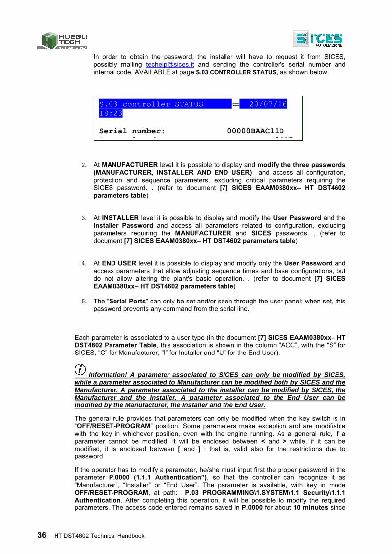
36 HT DST4602 Technical Handbook
In order to obtain the password, the installer will have to request it from SICES, possibly mailing [email protected] and sending the controller's serial number and internal code, AVAILABLE at page S.03 CONTROLLER STATUS, as shown below.
2. At MANUFACTURER level it is possible to display and modify the three passwords (MANUFACTURER, INSTALLER AND END USER) and access all configuration, protection and sequence parameters, excluding critical parameters requiring the SICES password. . (refer to document [7] SICES EAAM0380xx– HT DST4602 parameters table)
3. At INSTALLER level it is possible to display and modify the User Password and the
Installer Password and access all parameters related to configuration, excluding parameters requiring the MANUFACTURER and SICES passwords. . (refer to document [7] SICES EAAM0380xx– HT DST4602 parameters table)
4. At END USER level it is possible to display and modify only the User Password and
access parameters that allow adjusting sequence times and base configurations, but do not allow altering the plant's basic operation. . (refer to document [7] SICES EAAM0380xx– HT DST4602 parameters table)
5. The “Serial Ports” can only be set and/or seen through the user panel; when set, this password prevents any command from the serial line.
Each parameter is associated to a user type (in the document [7] SICES EAAM0380xx– HT DST4602 Parameter Table, this association is shown in the column "ACC”, with the "S” for SICES, "C” for Manufacturer, "I” for Installer and "U” for the End User).
Information! A parameter associated to SICES can only be modified by SICES, while a parameter associated to Manufacturer can be modified both by SICES and the Manufacturer. A parameter associated to the installer can be modified by SICES, the Manufacturer and the Installer. A parameter associated to the End User can be modified by the Manufacturer, the Installer and the End User.
The general rule provides that parameters can only be modified when the key switch is in “OFF/RESET-PROGRAM” position. Some parameters make exception and are modifiable with the key in whichever position, even with the engine running. As a general rule, if a parameter cannot be modified, it will be enclosed between < and > while, if it can be modified, it is enclosed between [ and ] : that is, valid also for the restrictions due to password
If the operator has to modify a parameter, he/she must input first the proper password in the parameter P.0000 (1.1.1 Authentication”), so that the controller can recognize it as “Manufacturer”, “Installer” or “End User”. The parameter is available, with key in mode OFF/RESET-PROGRAM, at path: P.03 PROGRAMMING\1.SYSTEM\1.1 Security\1.1.1 Authentication. After completing this operation, it will be possible to modify the required parameters. The access code entered remains saved in P.0000 for about 10 minutes since
S.03 controller STATUS 20/07/06 18:23 Serial number: 00000BAAC11D I t l d 2415
HT DST4602 Technical Handbook 37
the end of programming. After this time, the code is automatically reset to zero and must be re-entered to access programming again.
It is possible to customize the user type passwords through the parameter P.0001 (Manufacturer), P.0002 (Installer) and P.0003 (End User), available in the path P.03 PROGRAMMING\1.SYSTEM\1.1 Security\1.1.2 Password configuration. Value "0” for these parameters means no password set. The following examples show all the combinations for passwords assignment.
Example 1: P.0001=0 P.0002=0 P.0003=0
Any operator is seen as a "manufacturer”, with no need of setting anything in “P.0000-Access code”. Therefore, all parameters, excluding critical ones, can be modified by anyone (controller's default mode).
Example 2: P.0001=0 P.0002=0 P.0003=”uuu”
No parameter modification is allowed. When entering the “uuu” code in “P.0000-Access code”, the operator is identified as “End User” but, as no password is associated to “Installer” and “Manufacturer”, the controller acknowledges him/her as "Manufacturer”. After entering this code, all parameters, excluding critical ones, can be modified.
Example 3: P.0001=0 P.0002=”iii” P.0003=”uuu”
No parameter modification is allowed. When entering “uuu” in “P.0000-Access code”, the operator is identified as “End User” and is allowed to modify all parameters associated to the end user. By entering “iii”, the operator is identified as "installer” but, as no password is associated to the manufacturer, the controller identifies him/her as "manufacturer”. After entering this code, all parameters, excluding critical ones, can be modified.
Example 4: P.0001=”ccc” P.0002=”iii” P.0003=”uuu”
No parameter modification is allowed. When entering “uuu” in “P.0000-Access code”, the operator is identified as “End User” and is allowed to modify all parameters associated to the end user. By entering “iii”, the operator is identified as "installer” and is allowed to modify all parameters associated to “installer” and “end user”. When entering “ccc”, the operator is identified as "manufacturer” and is allowed to modify all controller parameters, excluding critical ones.
Example 5: P.0001=”ccc” P.0002=0 P.0003=0
As no password is associated to End User and Installer, programming the relevant parameters is allowed without entering anything in “P.0000-Access code”. To modify the parameters associated to Manufacturer, simply enter “ccc” in “P.0000-Access code”.
Example 6: P.0001=0 P.0002=”iii” P.0003=0
As no password is associated to End User, programming the relevant parameters is allowed without entering anything in “P.0000-Access code”. When entering “iii” in “P.0000-Access code” the operator is identified as “installer” but, as no password is associated to “manufacturer”, the controller identifies him/her as "manufacturer”. After entering this code, all parameters, excluding critical ones, can be modified.
Example 8: P.0001=”ccc” P.0002=”iii” P.0003=0
As no password is associated to End User, programming the relevant parameters is allowed without entering anything in “P.0000-Access code”. When entering “iii” in
38 HT DST4602 Technical Handbook
“P.0000-Access code”, the operator is identified as “installer” and is allowed to modify all controller parameters associated to installer and end user. When entering “ccc” in “P.0000-Access code”, the operator is identified as “manufacturer” and is allowed to modify all parameters, excluding critical ones.
Example 7: P.0001=”ccc” P.0002=0 P.0003=”uuu”
No parameter modification is allowed. When entering the “uuu” code in “P.0000-Access code”, the operator is identified as “end user” but, as no password is associated to “installer”, the controller identifies him/her as "installer”. Therefore, he/she is allowed to modify all controller parameters associated to installer and end user. When entering “ccc” in “P.0000-Access code”, the operator is identified as “manufacturer” and is allowed to modify all parameters, excluding critical ones.
Information! A parameter value can always be read but it can only be modified in case the "P.0000-Access code” contains a proper password. Parameters P.0001, P.0002, P.0003 and P.0469 (serial ports password) are excluded: actually, they are not displayed in case "P.0000-Access code” does not contain a proper password.
Parameter P.0469 – Serial ports password can only be viewed and/or modified through operator panel and with at least Installer rights.
Information! when accessing programming and setting the password ("P.0000-Access code”), parameters P.0001, P.0002 and P.0003 might not be immediately displayed. To enable display, return to the previous menu and then re-enter.
Information! This is the reason why we recommend to set at least the “Manufacturer” password (P.0001): actually, in case someone else sets up this password, or a lower level one (even unwillingly) without providing information, no parameter modification will be possible anymore. On the other hand, knowing the “manufacturer” password will allow to cancel or modify the other passwords.
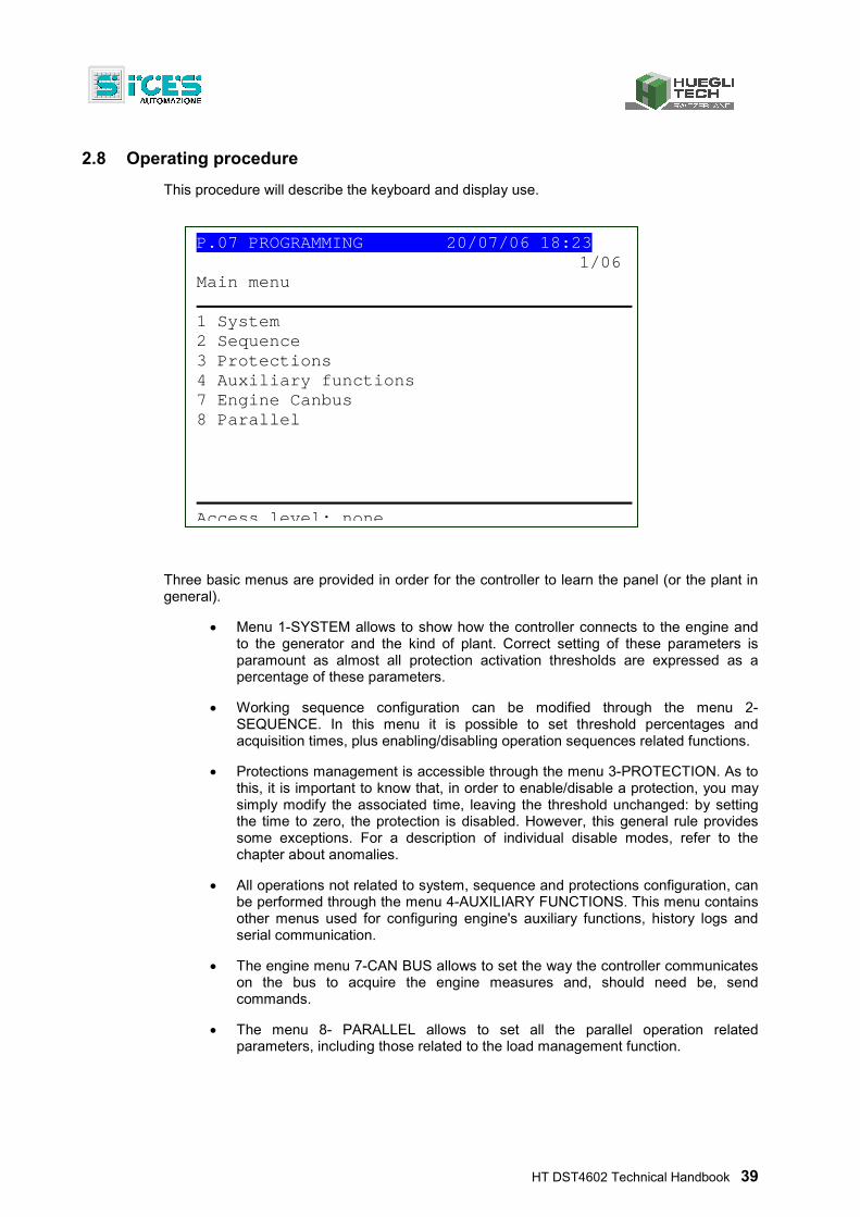
HT DST4602 Technical Handbook 39
2.8 Operating procedure
This procedure will describe the keyboard and display use.
Three basic menus are provided in order for the controller to learn the panel (or the plant in general).
Menu 1-SYSTEM allows to show how the controller connects to the engine and to the generator and the kind of plant. Correct setting of these parameters is paramount as almost all protection activation thresholds are expressed as a percentage of these parameters.
Working sequence configuration can be modified through the menu 2-SEQUENCE. In this menu it is possible to set threshold percentages and acquisition times, plus enabling/disabling operation sequences related functions.
Protections management is accessible through the menu 3-PROTECTION. As to this, it is important to know that, in order to enable/disable a protection, you may simply modify the associated time, leaving the threshold unchanged: by setting the time to zero, the protection is disabled. However, this general rule provides some exceptions. For a description of individual disable modes, refer to the chapter about anomalies.
All operations not related to system, sequence and protections configuration, can be performed through the menu 4-AUXILIARY FUNCTIONS. This menu contains other menus used for configuring engine's auxiliary functions, history logs and serial communication.
The engine menu 7-CAN BUS allows to set the way the controller communicates on the bus to acquire the engine measures and, should need be, send commands.
The menu 8- PARALLEL allows to set all the parallel operation related parameters, including those related to the load management function.
P.07 PROGRAMMING 20/07/06 18:23 1/06
Main menu
1 System 2 Sequence 3 Protections 4 Auxiliary functions 7 Engine Canbus 8 Parallel
Access level: none
40 HT DST4602 Technical Handbook
2.8.1 Entering programming mode
Programming is accessible in any controller operation status. Modifying parameters is only possible when the key switch is turned on OFF/RESET.
Only some parameters can be modified even during system operation.
To enter programming mode, use the UP ▲ and DOWN ▼ buttons till the base PROGRAMMING mode (P.03) screen is displayed.
Information! when in a mode that limits the use of vertical scrolling buttons, you may require to press repeatedly the EXIT button (this can occur when displaying history logs or during some operations, such as setting the fuel pump control mode).
While in the main page of the PROGRAMMING mode, press the SHIFT button; the lower status bar will display the following message:
Press ENTER to access program function. -
Then, press ENTER to access programming
The menu or variable selected before the last exit from programming are automatically displayed when starting the procedure (the main menu is displayed the first time you access).
2.8.2 Menu selection
Current menu name, selected menu item and number of menu items are always displayed in the first line. Menu items (submenus) are displayed in the following lines. The item selected is displayed in REVERSE. Use the UP▲ and DOWN ▼ buttons to scroll trough the menu to the lower and upper index items (pressing the UP ▲ button allows to directly cycle from the first item to the last one).
Press the ENTER button to access the selected (highlighted) sub-menu. Press the EXIT button to leave the menu (back to the previous menu or to the base screen if exiting programming in the main menu).
Pressing the SHIFT button will cause the following message to display in the lower status bar.
ACK/TEST+EXIT:default ENTER/EXIT:navig. menu
2.8.3 Parameters selection
The name of the current menu (in the example the menu “1-SYSTEM”) is always shown in the first line, followed by the numeric Id of the selected item and the number of menu items. The following lines are used to display single parameters. In detail:
The unambiguous parameter code (four decimal digits), followed by the description in the current language, is shown in second and/or third line.
Fourth line shows the variable value, included in square brackets, aligned to the right side. For some parameters, on the left side of the fourth line, a value is shown in some way related to the actual parameter value. For example, in the case of the rated generator power, the rated plant current is shown, derived from the rated generator voltage (P. 0102) and from the parameter itself (rated power, P.0106). Sometimes, this additional measure can be displayed for showing its absolute value, when the parameter is a percentage of other values, .
Use the UP▲ and/or DOWN ▼ buttons to scroll trough the menu to the lower and upper index items (pressing the UP ▲ button allows to directly cycle from the first item to the last one). Press
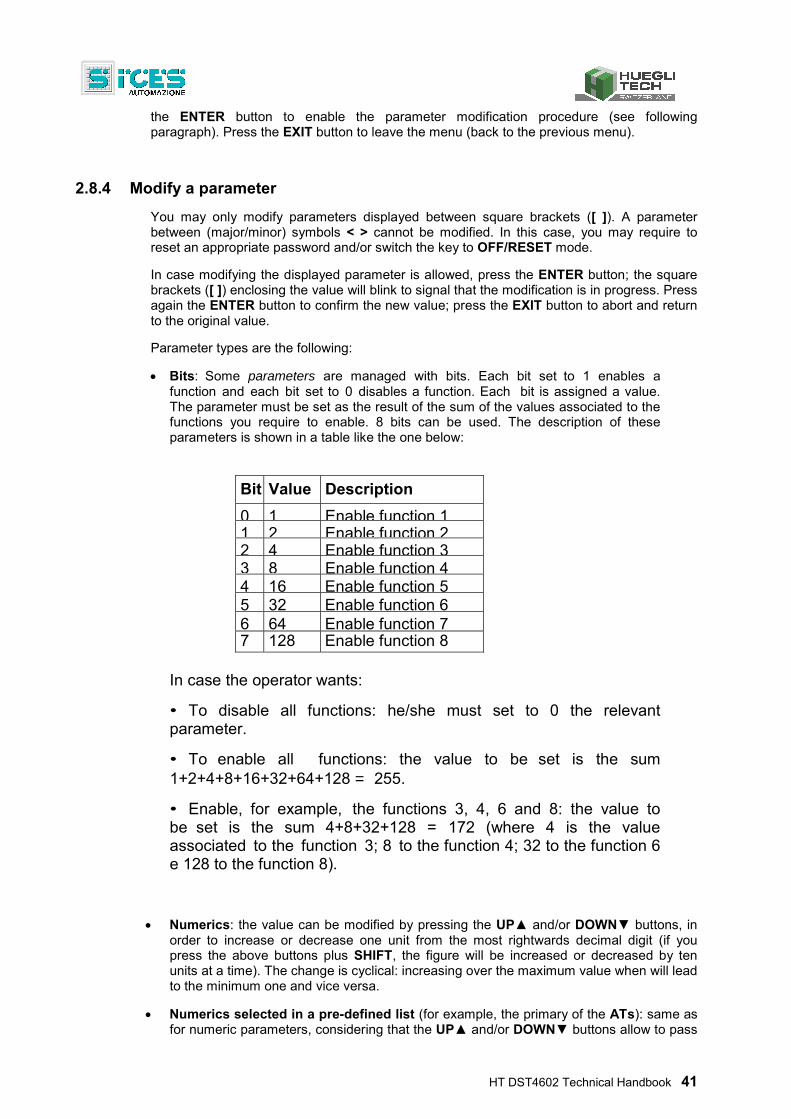
HT DST4602 Technical Handbook 41
the ENTER button to enable the parameter modification procedure (see following paragraph). Press the EXIT button to leave the menu (back to the previous menu).
2.8.4 Modify a parameter
You may only modify parameters displayed between square brackets ([ ]). A parameter between (major/minor) symbols < > cannot be modified. In this case, you may require to reset an appropriate password and/or switch the key to OFF/RESET mode.
In case modifying the displayed parameter is allowed, press the ENTER button; the square brackets ([ ]) enclosing the value will blink to signal that the modification is in progress. Press again the ENTER button to confirm the new value; press the EXIT button to abort and return to the original value.
Parameter types are the following:
Bits: Some parameters are managed with bits. Each bit set to 1 enables a function and each bit set to 0 disables a function. Each bit is assigned a value. The parameter must be set as the result of the sum of the values associated to the functions you require to enable. 8 bits can be used. The description of these parameters is shown in a table like the one below:
Bit Value Description
0 1 Enable function 11 2 Enable function 22 4 Enable function 33 8 Enable function 44 16 Enable function 55 32 Enable function 66 64 Enable function 77 128 Enable function 8
In case the operator wants:
• To disable all functions: he/she must set to 0 the relevant parameter.
• To enable all functions: the value to be set is the sum 1+2+4+8+16+32+64+128 = 255.
• Enable, for example, the functions 3, 4, 6 and 8: the value to be set is the sum 4+8+32+128 = 172 (where 4 is the value associated to the function 3; 8 to the function 4; 32 to the function 6 e 128 to the function 8).
Numerics: the value can be modified by pressing the UP▲ and/or DOWN▼ buttons, in order to increase or decrease one unit from the most rightwards decimal digit (if you press the above buttons plus SHIFT, the figure will be increased or decreased by ten units at a time). The change is cyclical: increasing over the maximum value when will lead to the minimum one and vice versa.
Numerics selected in a pre-defined list (for example, the primary of the ATs): same as for numeric parameters, considering that the UP▲ and/or DOWN▼ buttons allow to pass
42 HT DST4602 Technical Handbook
to the following/previous value (if you press the above buttons plus SHIFT you will pass to the value ten units after/before the current one).
Numerics selected in a number-string couples list (e.g. the type of pressure sensor): same as the previous point.
Time parameters: same as numerical parameters, with one exception: the controller manages the increment/decrement maintaining valid values (example: increasing from “00.59”, the value goes to “01.00” and not to “00.60”).
Strings (e.g. telephone numbers): in this case the display shows also a cursor indicating the currently selected character in the string. The UP▲ and/or DOWN▼ buttons work on the selected character (passing to the one after/before in the ASCII table. If you press the above buttons plus SHIFT, you will move to the one 10 units before/after). The ◄► buttons allow to select the character to be modified.
Information! you can only set the ASCII characters from 32 (Space) to 127 (Escape). It is not possible to set extended ASCII characters (over 127) and the control ones (from zero to 31).
Hexadecimal strings (e.g. output bitmaps): same as for the string parameters, but the selectable characters are only ”0-9” and “A-F” (only capitals).
2.8.5 Set up limits
The operator has not to worry about verifying that the set up value is acceptable for the controller since it is not possible to set up not acceptable values.
Obviously, this is only true for individual parameters.
However, it is possible to set two or more parameters in incongruent or incompatible ways. It is up to the operator to prevent this from occurring.
2.8.6 Exit from programming
There are three ways to exit programming mode:
Press the EXIT button 'n' times to scroll back to the main menu, then press it again to exit programming. The main menu will be displayed on the next access to programming.
Pressing and holding the EXIT button for one sec from any location: will cause instantaneous exit from programming; next access will return you to the very same point.
Turn the key switch on AUTO or MAN: next access will return you to the very same point.
HT DST4602 Technical Handbook 43
2.8.7 Loading default values
WARNING: This procedure permanently reloads all factory parameters according to access rights.
Sometimes, it may be useful to reload parameters factory values. To do so, first access programming, then press and hold the ACK/TEST and EXIT buttons simultaneously for five seconds. Reload of factory values will be confirmed by a message on the display.
When displaying a variable, if you press the SHIFT button, the lower status bar will display the following message:
ACK+EXIT (5s): default -
Information! factory values are reloaded only for parameters for which you are granted access rights.
2.8.7.1 Strings set-up Some parameters require setting or modifying data strings. In this case, pressing the ENTER button activates the blinking of the two square brackets [ ] enclosing the variable and, in addition, activates a cursor below the first character of the string. Use the ◄LEFT and ►RIGHT buttons to select the character to be modified. Then, use the UP and DOWN buttons to change the character selected. Repeat the procedure for each character to be changed. Press the ENTER button (confirm) or the EXIT button (abort) to end the procedure.
2.8.7.2 Direct access to the previous page It is possible to directly access the last displayed programming page. To do so, when leaving programming mode, instead of scrolling back through the menus till exiting, press and hold the EXIT button for about 2 seconds. Same result is achieved accessing the programming mode after the gen-set control module has automatically exited programming. This occurs in case you do not work on programming for over 60 full seconds, or in case the key switch is turned on MAN or AUTO.
2.8.7.3 Alarms and protection parameters
WARNING! Setting the trip time of the parameters to 0 disables the protection. Protections and alarms can generally be configured using dedicated variables. Generally, the trip time can also be configured.
2.8.8 Status information(S.xx) This mode provides information about system status. You may scroll through the pages using the ◄LEFT and ►RIGHT buttons. Page S.01 (STATUS) shows system status information. Part of this information is shown on the bottom status bar.
44 HT DST4602 Technical Handbook
The alarm page S.02 (ANOMALIES) is automatically displayed in case of an anomaly. This page contains also the diagnostic information about engines equipped with J1939 or MTU interface. - alarm codes, the first digit of the message is an alphabetic digit for identifying the alarm category (W - Warning, A - Alarm, D – Deactivation. Refer to Chapter 3), plus an identification number and the alarm status description. - engine diagnostic codes, in accordance with standard SAE J1939 or MTU specifications. In case of the standard J1939, when a signal is present, the SPN and FMI fault's codes, the number of occurrences (OC), a specific diagnostic code of the family of engines (DTC), and an explanatory text are displayed. For MTU engines the SPN, FMI and OC are not shown, but the DTC code and an alphanumeric description are always displayed.
Information! For more information refer to document EAAM0380xxXA “Parameters table”.
The engine diagnostic codes are stored (even if the engine deactivates them) until the yellow/red CanBus indicator light warning is acknowledged with the ACK/TEST button.
Page S.03 (CONTROLLER STATUS) contains some information about the device (Serial Number, Date, Firmware installed, Internal code); in addition, in this page is also possible to change the language.
Page S.04 (SERIAL PORTS) is dedicated to serial communication status. In case of operating errors, check the information in this page. When using a GSM modem, the telecom provider and radio signal are also shown. Received communication error counters are displayed. If the condition causing the malfunction has been removed, you can reset the error counters on this page. To activate the error reset function, press the ENTER button and scroll with the UP and DOWN buttons to the errors to be reset. Hold down the ACK/TEST + EXIT buttons for a few seconds until the message “RESET/DEFAULT” is displayed. To exit error selection, use the EXIT button.
Page S.05 (CAN BUS) is dedicated to the communication status of the following networks: CAN0 (ECU INTERFACE - Engine Control Unit.J1939 or MTU), CAN1 (PMCBUS: Power Management Communication Bus) and CAN2 (EX-BUS: Expansion-BUS).
Bus communication status. Three signals are possible: - ERROR-ACTIVE: normal operation - ERROR-PASSIVE: communication is working despite faults (errors). -BUS-OFF: controller disconnected from the bus due to too many errors. Communication error counters are displayed. If the condition causing the malfunction has been removed, in this page it is possible to force exit from the BUS-OFF condition. To activate the error reset function, press the ENTER button and scroll with the UP and DOWN buttons to the errors to be reset. Press and hold the ACK/TEST + EXIT buttons till the message “RESET/DEFAULT” is displayed. To exit error selection, use the EXIT button.
Pages S.06, S.07, S.08, S.09, S.10, S.11, S.12 and S.13 (SYSTEM STATUS) display the generic status of the digital inputs.
HT DST4602 Technical Handbook 45
Information! Digital inputs assigned as Warnings, Lockouts or Deactivations do not fall under this category. The generic status function, and their visualization priority in the pages, are pre-assigned when configuring system parameters.
Page S.14 (DIGITAL INPUTS) displays the status of the digital inputs of the controller and the expansion modules (available only if the DITEL expansion module/s is/are installed). Press the ENTER button to display three different screens (LOGIC STATE, PHYSICAL STATE, BY FUNCTION) showing the acquisition of digital inputs: - LOGIC STATE: Active or inactive level according to a logic configuration that inverts the electrical signal actually acquired. - PHYSICAL STATUS: Active or inactive level of the electrical signal actually acquired. - BY FUNCTION: Displays the status of the main events related to digital inputs.
Page S.15 (DIGITAL OUTPUTS) shows the status of the controller's digital outputs. The status of the expansion module outputs is only shown if the DITEL expansion module/s is/are installed. Press the ENTER button to display three different screens (LOGIC STATE, PHYSICAL STATE, BY FUNCTION) showing the state of digital outputs: - LOGIC STATE: Active or inactive output depending on a logic configuration that inverts the electrical level.
- PHYSICAL STATUS: Active or inactive output for the actual electrical level. - BY FUNCTION: Displays the main status of the digital outputs.
Page S.16 (ANALOG INPUTS) displays the value of the controller's analog inputs. The value of the expansion modules' analog inputs is only displayed if the DITEMP/DIVIT expansion module/s is/are installed.
Page S.17 (ANALOG OUTPUTS) displays the value of the controller's analog outputs. The value of the expansion modules' analog outputs is only displayed if the DANOUT expansion module/s is/are installed. Press the ENTER button to display two different screens (LOGIC STATE, BY FUNCTION) showing the analog outputs values and their function:
- LOGIC STATE: Displays the output value. - BY FUNCTION: Displays the output value and the pre-assigned function.
2.8.9 Electrical measures(M.xx)
Scroll through the various pages using the ◄LEFT e ►RIGHT buttons. This mode displays all the information on the measures performed by the controller on the electric lines. Page M.01 (SYSTEM) displays a unifilar wiring diagram of the system. The status of the switches, the MAINS/BUS, the GENERATOR and the electrical values depend on the plant configuration. Furthermore, a window for controlling the main active power and the power factor is displayed, according to system type. Page M.02 (MAINS) displays the MAINS or BUS electrical magnitudes.
46 HT DST4602 Technical Handbook
Page M.03(GENERATOR) displays the GENERATOR main electrical magnitudes. Page M.04(POWER VALUES) displays the total and phase power values, the active, reactive and apparent power values, and the power factor. Page M.05(ENERGY COUNTERS) displays the GENERATOR partial and total energy counters. Page M.06 (AUXILIARY MEASURES) (only available if “AUXILIARY CURRENT” and/or “INVERSE SEQUENCE CURRENT” protection is enabled). Page M.07 (SYNCHRONISATION) is used during synchronization. With the key switch in MAN mode, use the displayed synchroscope for manual synchronisation (only displayed if the internal synchronisation system is configured). Page M.08 (PARALLEL) displays the parameters used to monitor the parallel function.
2.8.10 Engine measures (E.xx)
Engine related measures are shown in this mode. Page E.01 (ENGINE) displays the engine main analog measures sensed by the analog sensors. Some engine measures are only displayed if the CAN J1939, MTU system is configured. Page E.02 (ENGINE COUNTERS) displays the engine's partial and total counters. Pages E.03 (TEMPERATURES), E.04 (PRESSURES/ENGINE TORQUE) and E.05 (AUXILIARY DATA) (only displayed if the CAN J1939 system is configured, MTU) contain information about engine temperatures, pressures, levels, etc. The number of pages displayed may depend on the type of engine set. Page E.06 (FUEL PUMP) (displayed only if FUEL PUMP management is configured) contains information about the fuel pump. The fuel pump management system can be modified in this page (refer to par. 6.2). Pages E.07, E.08, E.09, E.10, E.11, E.12, E.13 and E.14 (EXTERNAL MEASURES) (displayed only if the DITEMP/DIVIT expansion module/s is/are installed and/or the device inputs are configured for generic measures).
Information! The analog inputs pre-assigned for main measures do not fall under this category.
2.8.11 PMCB(B.xx) Power Management Communication Bus
Page B.01 (CONTROLLERS ON PMCBUS) displays status information about the PMCB (Power Management Communication Bus) network. This includes the number of network devices, the load function operating mode, the pilot generator identifier and the priority list. Page B.02 (GENERATORS) displays measures (Power reference, Power delivery, Reactive power, Operating hours and Status) of power values for gen-sets on the PMCBUS (Power Management Communication Bus) network.
HT DST4602 Technical Handbook 47
Page B.03 (TOTALS ON PMCBUS) displays measures (Power reference, Power delivery, Reactive power, Active energy and Reactive energy) for the total energy produced by all the gen-sets on the PMCBUS(Power Management Communication Bus) network. Page B.04 (LOAD MANAGEMENT) displays all the information relating to load management configuration on the PMCBUS(Power Management Communication Bus) network.
WARNING! Changes to the pilot generator should only be made by qualified personnel. In this screen, by pressing the ENTER button and the UP and DOWN buttons you may modify the master gen-set.
Information! Refer to the following document for the meaning of the parameters: EAAM0380XX (Parameters Table).
2.8.12 History logs(H.xx)
2.8.12.1 How to visualize the archives
When in operation and not in OFF/RESET mode, the controller performs periodical or on-event recordings that can be partially configured with programming parameters.
The controller manages three types of archive:
1. Events
2. Analog archive
3. Engine-DTC
The history logs can be accessed in any controller working status. To access archive visualization, press the ▲ and ▼ buttons till the HISTORY LOGS (H.01) page is displayed.
Information! when in a mode limiting the use of vertical scroll buttons you may require to press repeatedly the EXIT button.
Press the SHIFT button when the main page of HISTORY LOGS is displayed; the lower status bar will display the following message:
Press ENTER to view history logs -
Then press ENTER to enable the mode (moving to page “H.03”).
At the start of the procedure, the menu of the various archives functions is displayed.
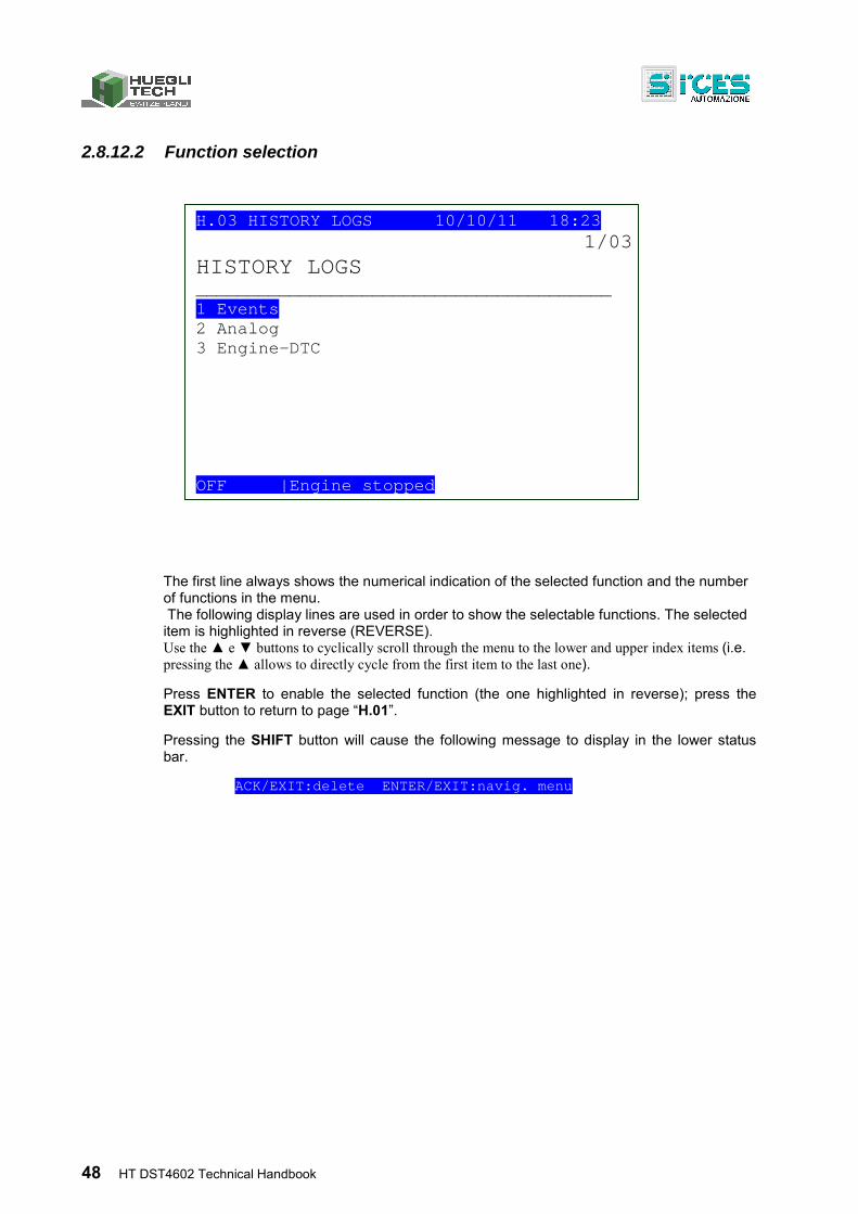
48 HT DST4602 Technical Handbook
2.8.12.2 Function selection
The first line always shows the numerical indication of the selected function and the number of functions in the menu. The following display lines are used in order to show the selectable functions. The selected item is highlighted in reverse (REVERSE). Use the ▲ e ▼ buttons to cyclically scroll through the menu to the lower and upper index items (i.e. pressing the ▲ allows to directly cycle from the first item to the last one).
Press ENTER to enable the selected function (the one highlighted in reverse); press the EXIT button to return to page “H.01”.
Pressing the SHIFT button will cause the following message to display in the lower status bar.
ACK/EXIT:delete ENTER/EXIT:navig. menu
H.03 HISTORY LOGS 10/10/11 18:23 1/03
HISTORY LOGS ________________________________________ 1 Events 2 Analog 3 Engine-DTC OFF |Engine stopped
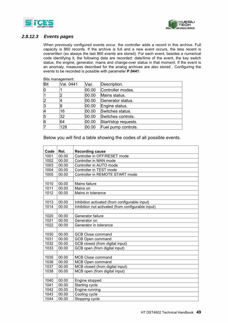
HT DST4602 Technical Handbook 49
2.8.12.3 Events pages
When previously configured events occur, the controller adds a record in this archive. Full capacity is 860 records. If the archive is full and a new event occurs, the less recent is overwritten (so always the last 860 events are stored). For each event, besides a numerical code identifying it, the following data are recorded: date/time of the event, the key switch status, the engine, generator, mains and change-over status in that moment. If the event is an anomaly, measures described for the analog archives are also stored . Configuring the events to be recorded is possible with parameter P.0441:
Bits management: Bit Val. 0441 Ver. Description. 0 1 00.00 Controller modes. 1 2 00.00 Mains status. 2 4 00.00 Generator status. 3 8 00.00 Engine status. 4 16 00.00 Switches status. 5 32 00.00 Switches controls. 6 64 00.00 Start/stop requests. 7 128 00.00 Fuel pump controls.
Below you will find a table showing the codes of all possible events.
Code Rel. Recording cause 1001 00.00 Controller in OFF/RESET mode 1002 00.00 Controller in MAN mode 1003 00.00 Controller in AUTO mode 1004 00.00 Controller in TEST mode 1005 00.00 Controller in REMOTE START mode 1010 00.00 Mains failure 1011 00.00 Mains on 1012 00.00 Mains in tolerance 1013 00.00 Inhibition activated (from configurable input) 1014 00.00 Inhibition not activated (from configurable input) 1020 00.00 Generator failure 1021 00.00 Generator on 1022 00.00 Generator in tolerance 1030 00.00 GCB Close command 1031 00.00 GCB Open command 1032 00.00 GCB closed (from digital input) 1033 00.00 GCB open (from digital input) 1035 00.00 MCB Close command 1036 00.00 MCB Open command 1037 00.00 MCB closed (from digital input) 1038 00.00 MCB open (from digital input) 1040 00.00 Engine stopped 1041 00.00 Starting cycle 1042 00.00 Engine running 1043 00.00 Cooling cycle 1044 00.00 Stopping cycle
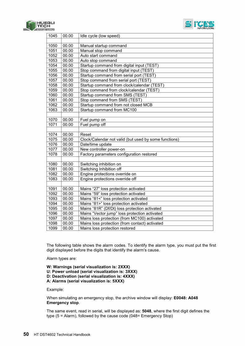
50 HT DST4602 Technical Handbook
1045 00.00 Idle cycle (low speed) 1050 00.00 Manual startup command 1051 00.00 Manual stop command 1052 00.00 Auto start command 1053 00.00 Auto stop command 1054 00.00 Startup command from digital input (TEST) 1055 00.00 Stop command from digital input (TEST) 1056 00.00 Startup command from serial port (TEST) 1057 00.00 Stop command from serial port (TEST) 1058 00.00 Startup command from clock/calendar (TEST) 1059 00.00 Stop command from clock/calendar (TEST) 1060 00.00 Startup command from SMS (TEST) 1061 00.00 Stop command from SMS (TEST) 1062 00.00 Startup command from not closed MCB 1063 00.00 Startup command from MC100 1070 00.00 Fuel pump on 1071 00.00 Fuel pump off 1074 00.00 Reset 1075 00.00 Clock/Calendar not valid (but used by some functions) 1076 00.00 Date/time update 1077 00.00 New controller power-on 1078 00.00 Factory parameters configuration restored 1080 00.00 Switching inhibition on 1081 00.00 Switching Inhibition off 1082 00.00 Engine protections override on 1083 00.00 Engine protections override off 1091 00.00 Mains “27” loss protection activated 1092 00.00 Mains “59” loss protection activated 1093 00.00 Mains “81<” loss protection activated 1094 00.00 Mains “81>” loss protection activated 1095 00.00 Mains “81R” (Df/Dt) loss protection activated 1096 00.00 Mains “Vector jump” loss protection activated 1097 00.00 Mains loss protection (from MC100) activated 1098 00.00 Mains loss protection (from contact) activated 1099 00.00 Mains loss protection restored
The following table shows the alarm codes. To identify the alarm type, you must put the first digit displayed before the digits that identify the alarm's cause.
Alarm types are:
W: Warnings (serial visualization is: 2XXX) U: Power unload (serial visualization is: 3XXX) D: Deactivation (serial visualization is: 4XXX) A: Alarms (serial visualization is: 5XXX)
Example:
When simulating an emergency stop, the archive window will display: E0048: A048 Emergency stop.
The same event, read in serial, will be displayed as: 5048, where the first digit defines the type (5 = Alarm), followed by the cause code (048= Emergency Stop)
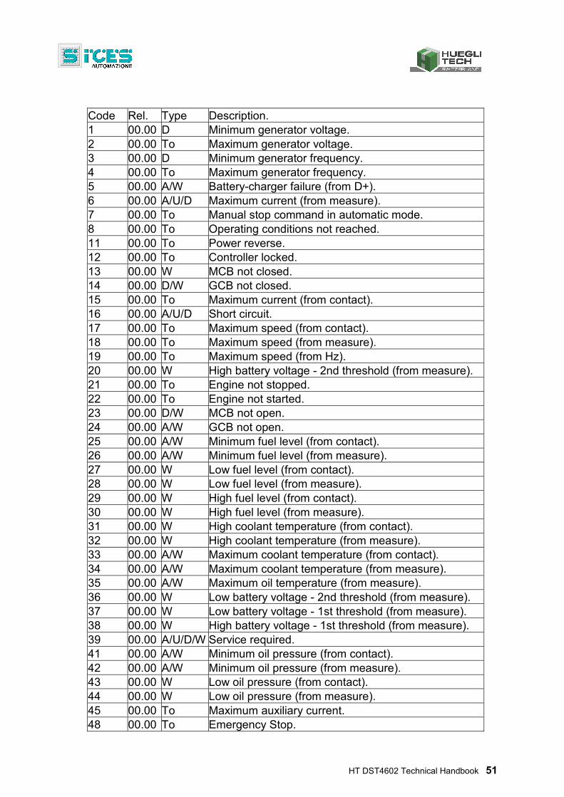
HT DST4602 Technical Handbook 51
Code Rel. Type Description. 1 00.00 D Minimum generator voltage. 2 00.00 To Maximum generator voltage. 3 00.00 D Minimum generator frequency. 4 00.00 To Maximum generator frequency. 5 00.00 A/W Battery-charger failure (from D+). 6 00.00 A/U/D Maximum current (from measure). 7 00.00 To Manual stop command in automatic mode. 8 00.00 To Operating conditions not reached. 11 00.00 To Power reverse. 12 00.00 To Controller locked. 13 00.00 W MCB not closed. 14 00.00 D/W GCB not closed. 15 00.00 To Maximum current (from contact). 16 00.00 A/U/D Short circuit. 17 00.00 To Maximum speed (from contact). 18 00.00 To Maximum speed (from measure). 19 00.00 To Maximum speed (from Hz). 20 00.00 W High battery voltage - 2nd threshold (from measure). 21 00.00 To Engine not stopped. 22 00.00 To Engine not started. 23 00.00 D/W MCB not open. 24 00.00 A/W GCB not open. 25 00.00 A/W Minimum fuel level (from contact). 26 00.00 A/W Minimum fuel level (from measure). 27 00.00 W Low fuel level (from contact). 28 00.00 W Low fuel level (from measure). 29 00.00 W High fuel level (from contact). 30 00.00 W High fuel level (from measure). 31 00.00 W High coolant temperature (from contact). 32 00.00 W High coolant temperature (from measure). 33 00.00 A/W Maximum coolant temperature (from contact). 34 00.00 A/W Maximum coolant temperature (from measure). 35 00.00 A/W Maximum oil temperature (from measure). 36 00.00 W Low battery voltage - 2nd threshold (from measure). 37 00.00 W Low battery voltage - 1st threshold (from measure). 38 00.00 W High battery voltage - 1st threshold (from measure). 39 00.00 A/U/D/W Service required. 41 00.00 A/W Minimum oil pressure (from contact). 42 00.00 A/W Minimum oil pressure (from measure). 43 00.00 W Low oil pressure (from contact). 44 00.00 W Low oil pressure (from measure). 45 00.00 To Maximum auxiliary current. 48 00.00 To Emergency Stop.
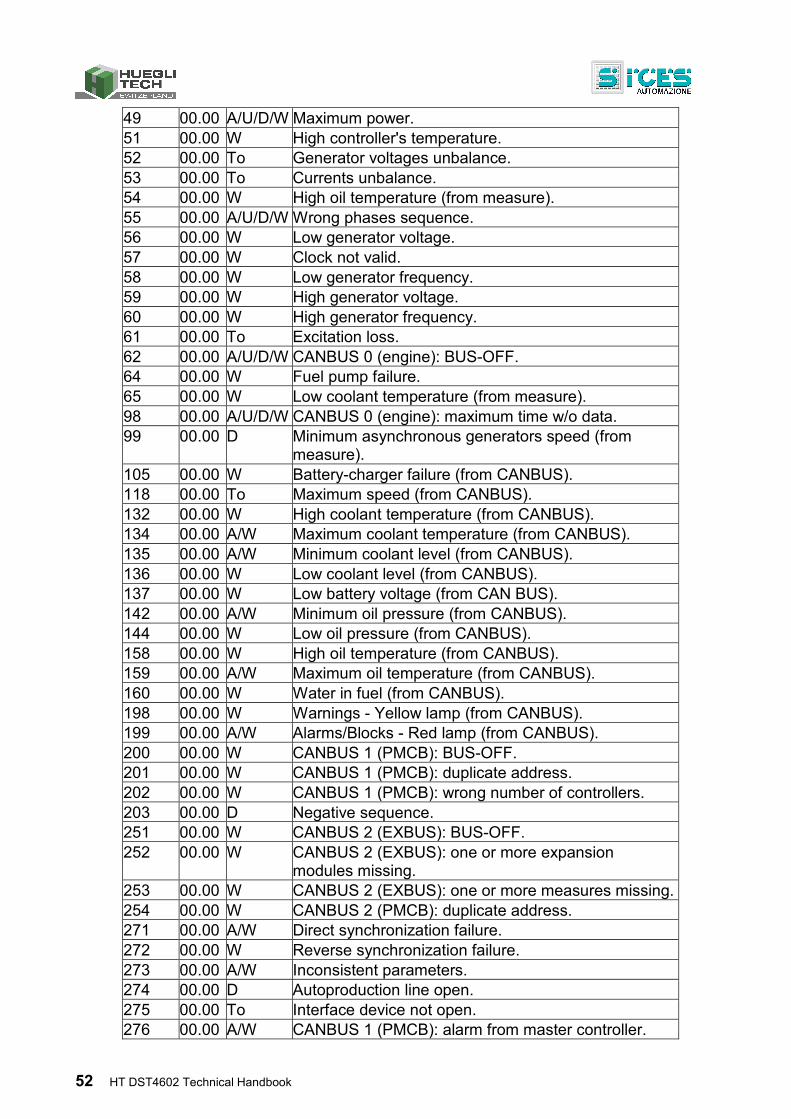
52 HT DST4602 Technical Handbook
49 00.00 A/U/D/W Maximum power. 51 00.00 W High controller's temperature. 52 00.00 To Generator voltages unbalance. 53 00.00 To Currents unbalance. 54 00.00 W High oil temperature (from measure). 55 00.00 A/U/D/W Wrong phases sequence. 56 00.00 W Low generator voltage. 57 00.00 W Clock not valid. 58 00.00 W Low generator frequency. 59 00.00 W High generator voltage. 60 00.00 W High generator frequency. 61 00.00 To Excitation loss. 62 00.00 A/U/D/W CANBUS 0 (engine): BUS-OFF. 64 00.00 W Fuel pump failure. 65 00.00 W Low coolant temperature (from measure). 98 00.00 A/U/D/W CANBUS 0 (engine): maximum time w/o data. 99 00.00 D Minimum asynchronous generators speed (from
measure). 105 00.00 W Battery-charger failure (from CANBUS). 118 00.00 To Maximum speed (from CANBUS). 132 00.00 W High coolant temperature (from CANBUS). 134 00.00 A/W Maximum coolant temperature (from CANBUS). 135 00.00 A/W Minimum coolant level (from CANBUS). 136 00.00 W Low coolant level (from CANBUS). 137 00.00 W Low battery voltage (from CAN BUS). 142 00.00 A/W Minimum oil pressure (from CANBUS). 144 00.00 W Low oil pressure (from CANBUS). 158 00.00 W High oil temperature (from CANBUS). 159 00.00 A/W Maximum oil temperature (from CANBUS). 160 00.00 W Water in fuel (from CANBUS). 198 00.00 W Warnings - Yellow lamp (from CANBUS). 199 00.00 A/W Alarms/Blocks - Red lamp (from CANBUS). 200 00.00 W CANBUS 1 (PMCB): BUS-OFF. 201 00.00 W CANBUS 1 (PMCB): duplicate address. 202 00.00 W CANBUS 1 (PMCB): wrong number of controllers. 203 00.00 D Negative sequence. 251 00.00 W CANBUS 2 (EXBUS): BUS-OFF. 252 00.00 W CANBUS 2 (EXBUS): one or more expansion
modules missing. 253 00.00 W CANBUS 2 (EXBUS): one or more measures missing.254 00.00 W CANBUS 2 (PMCB): duplicate address. 271 00.00 A/W Direct synchronization failure. 272 00.00 W Reverse synchronization failure. 273 00.00 A/W Inconsistent parameters. 274 00.00 D Autoproduction line open. 275 00.00 To Interface device not open. 276 00.00 A/W CANBUS 1 (PMCB): alarm from master controller.
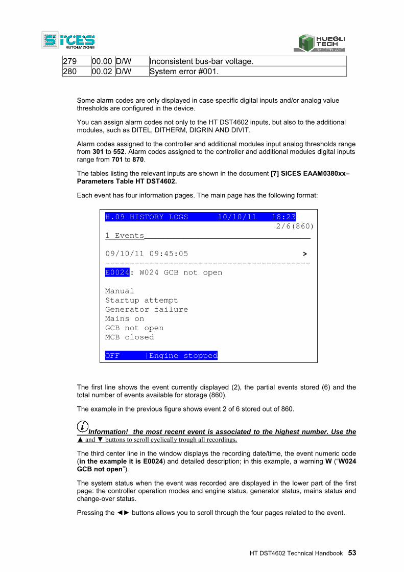
HT DST4602 Technical Handbook 53
279 00.00 D/W Inconsistent bus-bar voltage. 280 00.02 D/W System error #001.
Some alarm codes are only displayed in case specific digital inputs and/or analog value thresholds are configured in the device.
You can assign alarm codes not only to the HT DST4602 inputs, but also to the additional modules, such as DITEL, DITHERM, DIGRIN AND DIVIT.
Alarm codes assigned to the controller and additional modules input analog thresholds range from 301 to 552. Alarm codes assigned to the controller and additional modules digital inputs range from 701 to 870.
The tables listing the relevant inputs are shown in the document [7] SICES EAAM0380xx– Parameters Table HT DST4602.
Each event has four information pages. The main page has the following format:
The first line shows the event currently displayed (2), the partial events stored (6) and the total number of events available for storage (860).
The example in the previous figure shows event 2 of 6 stored out of 860.
Information! the most recent event is associated to the highest number. Use the ▲ and ▼ buttons to scroll cyclically trough all recordings.
The third center line in the window displays the recording date/time, the event numeric code (in the example it is E0024) and detailed description; in this example, a warning W (“W024 GCB not open”).
The system status when the event was recorded are displayed in the lower part of the first page: the controller operation modes and engine status, generator status, mains status and change-over status.
Pressing the ◄► buttons allows you to scroll through the four pages related to the event.
H.09 HISTORY LOGS 10/10/11 18:23 2/6(860)
1 Events__________________________________ 09/10/11 09:45:05 > ------------------------------------------ E0024: W024 GCB not open Manual Startup attempt Generator failure Mains on GCB not open MCB closed OFF |Engine stopped
54 HT DST4602 Technical Handbook
In addition to basic date/time and event code information, the second, third and fourth page display all the analog values recorded at the moment the event occurred, and the relevant descriptions.
The detailed measures are:
Mains Hz (Mains frequency) Mains V 12 (L1-L2 mains phase-to-phase voltage) Mains V 23* (L2-L3 mains phase-to-phase voltage) Mains V 31* (L3-L1 mains phase-to-phase voltage) Generator Hz (Generator frequency) Generator V12 (L1-L2 generator phase-to-phase voltage) Generator V23* (L2-L3 generator phase-to-phase voltage) Generator V 31* (L3-L1 generator phase-to-phase voltage) A1 (L1 generator phase current) A2* (L2 generator phase current) A3 * (L3 generator phase current) kVA T (System total apparent power) kW T (System total active power) kvar T (System total reactive power)
P.F. T (Total power factor and load type: i=inductive, c=capacitive)
Battery voltage (Vdc) Engine speed (rpm) Oil pressure (bar) Coolant temperature (°C) Fuel level * if mono-phase, the second and third voltage/current are dashed
2.8.12.4 Pages for analogs
The controller records the analog magnitudes described below (with engine On or Off); the recording frequency is configured with the parameter P.0442 (seconds) and P.0443 (seconds):
Main information about operation mode, engine status, voltages presence and status of change-over switches.
Mains phase-to-phase voltages and frequency.
Generator phase-to-phase voltages, currents and frequency.
Active, reactive and apparent powers, the power factor and the type of plant total load.
Starting battery voltage, engine rotation speed, coolant temperature, oil pressure and engine fuel level.
Each record is associated with its date/time. The measures not acquired (because the controller was not set to acquire them) are replaced by dashes. This archive provides a total
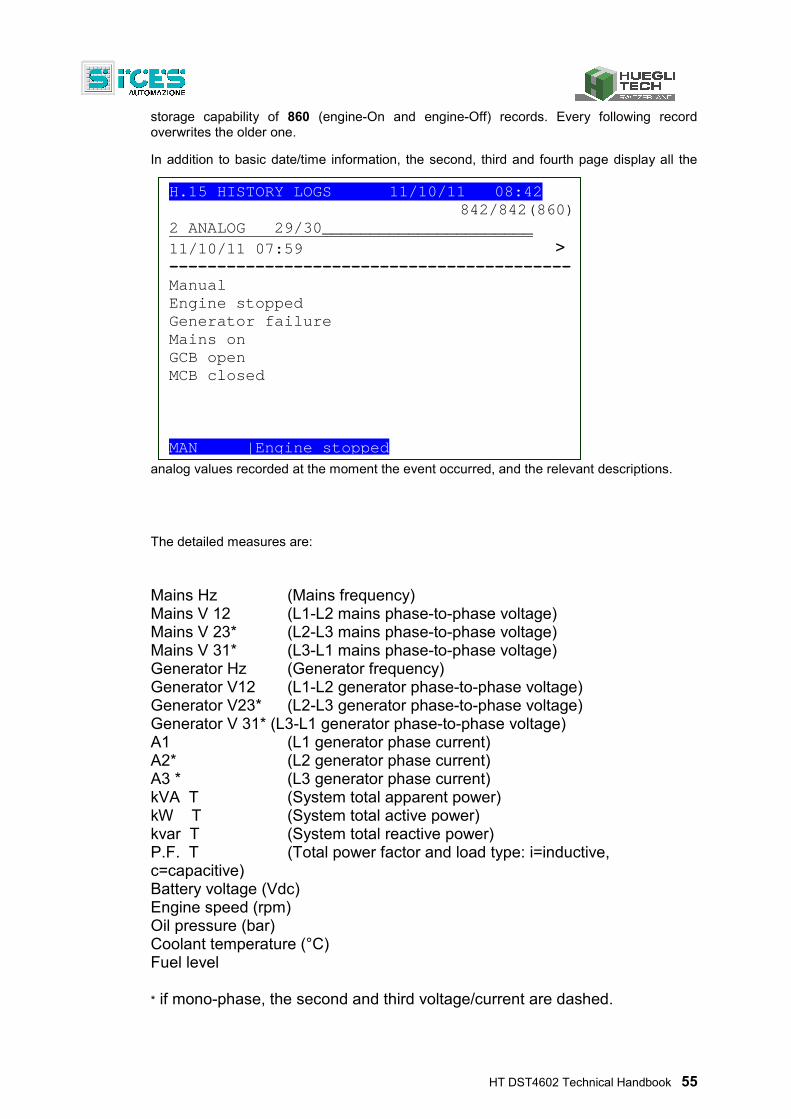
HT DST4602 Technical Handbook 55
storage capability of 860 (engine-On and engine-Off) records. Every following record overwrites the older one.
In addition to basic date/time information, the second, third and fourth page display all the
analog values recorded at the moment the event occurred, and the relevant descriptions.
The detailed measures are:
Mains Hz (Mains frequency) Mains V 12 (L1-L2 mains phase-to-phase voltage) Mains V 23* (L2-L3 mains phase-to-phase voltage) Mains V 31* (L3-L1 mains phase-to-phase voltage) Generator Hz (Generator frequency) Generator V12 (L1-L2 generator phase-to-phase voltage) Generator V23* (L2-L3 generator phase-to-phase voltage) Generator V 31* (L3-L1 generator phase-to-phase voltage) A1 (L1 generator phase current) A2* (L2 generator phase current) A3 * (L3 generator phase current) kVA T (System total apparent power) kW T (System total active power) kvar T (System total reactive power)
P.F. T (Total power factor and load type: i=inductive, c=capacitive) Battery voltage (Vdc) Engine speed (rpm) Oil pressure (bar) Coolant temperature (°C) Fuel level * if mono-phase, the second and third voltage/current are dashed.
H.15 HISTORY LOGS 11/10/11 08:42 842/842(860)
2 ANALOG 29/30______________________ 11/10/11 07:59 > ------------------------------------------ Manual Engine stopped Generator failure Mains on GCB open MCB closed MAN |Engine stopped
56 HT DST4602 Technical Handbook
2.8.12.5 Locked recordings
INFORMATION! Analog recordings are temporarily Off when the key switch is in “OFF/RESET” mode
Recordings are locked; all the windows of the History logs display an intermittent “Locked” message. In this situation, the controller's internal counters keep decreasing the time left to the expiry of the next recording.
When the operation mode shifts from “OFF/RESET” to “MAN” or “AUTO” mode, a check is performed in order to verify whether some recording counter expired. If so, the recorded date and time of the status change are stored, otherwise the count continues till the next recording is stored.
Example:
Parameters set for: Recording “engine-On” events every 20 secs and “engine-Off” events every 40 secs.
Time/Date: 12:45 11/10/11 Shifting from “MAN”/“AUTO” to “OFF/RESET” mode;
Recordings are “Locked”.
Time/Date: 13:10 11/10/11 Shifting from “OFF/RESET” to “MAN”/“AUTO” mode.
25 secs elapsed, analog “engine-Off” recording will start within 15 secs (40 secs).
2.8.12.6 Engine diagnostics pages (DTC)
INFORMATION! Only for engine connection CANBUS version (ECU Interface – CAN0).
The controller records only the DTCs the engine control unit (ECU interface) sends over the CANBUS line.
Basically, depending on the installed engine, the diagnostic message consists of the DTC, SPN and fault description. This archive have can store up to 16 records. Every following record overwrites the older one.
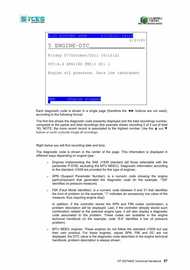
HT DST4602 Technical Handbook 57
Each diagnostic code is shown in a single page (therefore the ◄► buttons are not used), according to the following format:
The first line shows the diagnostic code presently displayed and the total recordings number, compared to the partial and total recordings (the example shows recording 2 of 2 out of total 16). NOTE: the more recent record is associated to the highest number. Use the ▲ and ▼ buttons to scroll cyclically trough all recordings.
Right below you will find recording date and time.
The diagnostic code is shown in the center of the page. This information is displayed in different ways depending on engine type :
o Engines implementing the SAE J1939 standard (all those selectable with the parameter P.0700, excluding the MTU MDEC). Diagnostic information according to the standard J1939 are provided for this type of engines:
o SPN (Suspect Parameter Number): is a numeric code showing the engine part/component that generated the diagnostic code (in the example, “100” identifies oil pressure measure).
o FMI (Fault Mode Identifier): is a numeric code between 0 and 31 that identifies the kind of problem (in the example, “1” indicates an excessively low value of the measure, thus requiring engine stop).
In addition, if the controller stored the SPN and FMI codes combination, a problem description will be displayed. Last, if the controller already stored such combination related to the selected engine type, it will also display a diagnostic code associated to the problem. These codes are available in the engine technical handbook (in the example, code “6.6” identifies a low oil pressure problem).
o MTU MDEC engines. These engines do not follow the standard J1939 but use their own protocol. For these engines, values SPN, FMI and OC are not displayed; the DTC value is the diagnostic code described in the engine technical handbook; problem description is always shown.
H.21 HISTORY LOGS 07/10/11 18:23 2/2(16)
5 ENGINE-DTC________________ Friday 07/October/2011 16:12:22 DTC:6.6 SPN:100 FMI:1 OC: 1 Engine oil pressure, Data low (shutdown) MAN |Engine stopped -
58 HT DST4602 Technical Handbook
2.8.13 Exit from archives visualization
There are two ways to exit from archive visualization:
Press the EXIT button 'n' times to scroll back to page H.01
Rotate the key switch.
In both cases, page H.01 will display; you may move to other display modes using the ▲ and ▼ buttons.
3. Working sequence 3.1 Plant types
HT DST4602 implements management logics for some types of plant. This allows to greatly simplify panel implementation.
Supported types are :
SPM (Single Prime Mover) Single plant station production
SSB (Single Stand-by) Single emergency plant
SSB + SSTP (Single Stand-By + Single Short Time Parallel) Single short time parallel emergency plant
SPtM + SSB (Single Parallel to Mains + Single Stand-By) Single mains short time parallel plant also working in station
SPtM (Single Parallel to Mains) Single mains short time parallel plant
MPM (Multiple Prime Mover) Multiple plant station production
MSB (Multiple Stand-By) Multiple emergency plant
MSB + MSTP (Multiple Stand-By + Multiple Short Time Parallel ) Multiple emergency plant with short time parallel
MPtM (Multiple Parallel to Mains) Multiple mains short time parallel plant
MPtM + MSB(Multiple Parallel to Mains + Multiple Stand-By) Multiple mains short time parallel plant also working in station
For more information refer to the document: [6] Parallel functions manual
Plant type can be set with the parameter P.0802 Plant type accessible through the menu 1 System, submenu 1.8 General.
INFORMATION! In order to avoid inconsistent modifications of this parameter, a special temporary password, named PASSWORD SICES is mandatorily required for any parameter change.
3.2 Controller modes
HT DST4602 allows five management modes:
HT DST4602 Technical Handbook 59
OFF/RESET: the gen-set is stopped (or stopping), all anomalies cleared and all modifiable parameters can be accessed through programming. The GCB switch is open to isolate the generator from the loads and/or the parallel bars. The MCB is normally closed (anyway depending on plant type as some types cannot manage it).
MAN: the operator starts the gen-set, performs any required synchronization of the parallel bars or the mains and closes the GCB switch (the controller does not perform these functions automatically). The operator also stops the gen-set and opens the GCB switch. when the protections are enabled, should need be, the controller can open the GCB and stop the engine. In case of parallel plants, after manual operation of the GCB switch, the controller performs loading and unloading ramps, if conditions allow. In addition, with closed switch, it automatically performs the proper load management activities (LOAD SHARING, BASE LOAD, IMPORT/EXPORT, etc.). Managing the MCB switch depends on the type of plant. Accessing programming is allowed, though only some parameters can be modified.
AUTO: the controller starts and stops the gen-set, manages the GCB and MCB switches (with or w/o synchronization), performs loading and unloading ramps, manages any parallel load management (no operator intervention allowed). All protections are enabled. Access to programming is not allowed, though some parameters can be modified.
TEST: this operation mode is nearly identical toAUTO. The only difference is that the engine is anyway (automatically) started even with mains and/or inhibition contact On. The parameter P.0222 Enabling test loading allows sending the controller an automatic closing command for the GCB switch. However, the operator can send a switch closing command as in MAN mode (only difference being that any synchronization is automatically performed by the controller).
60 HT DST4602 Technical Handbook
In case of parallel plants, after manual or automatic commands from the GCB switch, provided proper conditions, the controller automatically performs loading and unloading ramps. In addition, when the switch is closed, the controller automatically performs the appropriate loading management operations (LOAD SHARING, BASE LOAD, IMPORT/EXPORT, etc.). After the periodic test (or when the requesting contact is inactive) the GCB switch opens automatically and the engine is stopped by standard procedure. The MCB switch management only depends on plant type. The controller automatically switches from TEST to AUTO in case existing conditions require an automatic intervention by the gen-set. Access to programming is allowed, though only some parameters can be modified.
REMOTE START: nearly identical to AUTO. The only difference is that the engine is anyway (automatically) started even with mains and/or inhibition contact On. AUTO mode supersedes TEST mode (i.e., it can interrupt or replace the periodic test). The operator is not allowed to manually operate the GCB and MCB switches. The controller automatically shifts from REMOTE START to AUTO in case of conditions requiring automatic gen-set intervention. Access to programming is allowed, though only some parameters can be modified.
The first three modes are selected by means of the key switch on the controller panel. On the other hand, to enable the TEST mode requires the controller being first set to AUTO w/o any AUTOMATIC start request (refer to the engine sequence description). All possible TEST function activation modes are described below. The TEST mode is signaled by a statement in reverse in the lower left part of the LCD display. You can shift to TEST mode as follows:
o By simultaneously pressing the START and ACK/TEST buttons on the controller panel. Shifting to TEST mode is immediate. Press again those same buttons to return to AUTO mode.
o By properly setting the following parameters: P.0418 Weekly test calendar, P.0419 Test starting time, P.0420 Test starting duration. These parameters allow weekly programming of the time intervals for TEST mode engine start (to keep it efficient). In this case, shifting to TEST mode automatically occurs at set days and times. The controller returns to AUTO when the TEST time interval ends.
o Through a proper SMS command message (refer to the document describing the use of the serial port: [4] Serial communication). In order for this feature to be used, the parameter P.0420 Test starting duration shall not be set to zero.
HT DST4602 Technical Handbook 61
In this case, the controller shifts from TEST after receiving the SMS and returns to AUTO after the time P.0420 Test starting duration (min).
o From a PC connected to a serial port (with Modbus RTU protocol). The controller shifts to TEST after receiving the command from the serial port (password protection, refer to par. 2.7.1.2); then, returns to AUTO after receiving the opposite command or when it detects an interrupted serial connection (60 seconds w/o messages).
o When a digital input, properly set with code 2031 Test mode request is activated, the controller shifts to TEST when this input is activated and returns to AUTO when de-activated.
To activate the REMOTE START mode, the controller requires first to be in AUTO or TEST mode, w/o any AUTOMATIC start request (refer to the engine sequence description). In addition, in case an input is set to ENABLE REMOTE START REQUEST with a code 2701 in the parameters of any input, this input shall be active.
You may shift to REMOTE STARTUP in the following cases:
o By configuring a controller digital input for acquiring the REMOTE STARTUP REQUEST, code 2032, on any input. When this input is active, the controller shifts to REMOTE STARTUP; it deactivates when reverting to AUTO.
o By means of a proper command via SMS (refer to document [4] Serial communication). In this case, the controller shifts to START (password protection, refer to par. 2.7.1.2), after receiving the SMS, and reverts to AUTO when it receives the opposite command. In this case, you need to configure an input for acquiring the contact ENABLE REMOTE STARTUP REQUEST, code 2701, and the input shall be active (normally wired on a panel for enabling remote commands).
o From a PC connected to the serial port. The controller shifts to REMOTE STARTUP after receiving the command from the serial port; it then reverts to AUTO when receiving the opposite command (it remains in REMOTE STARTUP mode in case the serial connection is interrupted before receiving the opposite command). In this case you need to configure an input for acquiring the ENABLE REMOTE STARTUP, code 29 , and that input shall be active (normally wired on a panel switch for enabling remote commands).
3.3 Mains/Bus
HT DST4602 acquires plant mains/bus voltage (single phase or three phases), in order to command automatic engine startups and stops, mains parallel, gen-sets parallel (and loads switching), in Single Stand By (SSB) applications when mains fails.
The mains/bus shall be connected on the connector J24 for 400 Vac input, and on the connector J19 for 100 Vac input. On a three-phase system, ensure to connect the three phases and the neutral; on a single-phase system, ensure to connect the L1 phase on connector “1-L1” of J19 or J24 and the neutral on “2-L2+4-N” of J19 or J24.
Several parameters affect the mains/bus management:
P.0105: rated generator frequency. Also used as mains rated frequency. All thresholds associated to mains frequency are expressed as a percentage of this parameter.
P.0119: indicates a three-phases mains/bus (3) or a single-phase one (1).
62 HT DST4602 Technical Handbook
P.0116: rated mains/Bus voltage. Phase-to-phase rated voltage shall be set for three-phases systems; single-phase, for single phase systems. Thresholds are expressed as a percentage of it. If set to zero, mains voltage is always considered not present, even if physically connected.
NOTE: even if P.0116 is set to zero, mains voltage value is always measured and shown.
P.0117: primary value (in Volt) of any VT connected to connector J19 (100 Vac) or J24 (400 Vac).
P.0118: secondary value (in Volt) of any VT connected to connector J19 (100 Vac) or J24 (400 Vac).
P.0126 Bus/Mains sensor indication. (P.0126 = 0) or to mains (P.0126 = 1); obviously, in case J19 or J24 are used for parallel bar, the controller cannot directly read mains voltages and frequency.
P.0129 Neutral to controller connection condition (only valid for a three-phases system). On single-phase systems the parameter shall be set to 1.
P.0201: hysteresis applied to all the thresholds related to mains voltage. Percentage value of P.0116.
P.0203: mains low voltage threshold (percentage of P.0116); below this value, mains is considered anomalous and the engine is started.
P.0204: mains high voltage threshold (percentage of P.116); over this value mains is considered anomalous and the engine is started.
P.0236: mains low frequency threshold (percentage of P.0105); below this value, mains is considered anomalous and the engine is started.
P.0237: mains high frequency threshold (percentage of P.0105); over this value, mains is considered anomalous and the engine is started.
P.0238: mains voltages unbalance threshold (percentage of P.0116); over this value, mains is considered anomalous and the engine is started. Only applicable to three-phases systems.
P.0239: Rotation direction required for mains voltage. Only applicable to three-phases systems.
In order to assess the mains status, the controller can perform up to four different checks that can be individually disabled. These checks are individually described (with examples) below: please, remember that disabling both voltages and frequency checks is not possible (in this case, mains is always considered not present).
3.3.1.1 Frequency check
To disable this check, one of the following conditions shall be true:
P.0236 = 0 %.
P.0237 = 200 %.
P.0236 >= P.0237
Here follows an example about the various threshold used, including default values for a.m. parameters.
Parameter Description Default value Frequency in Hz
P.0105 Rated frequency 50 Hz 50.00
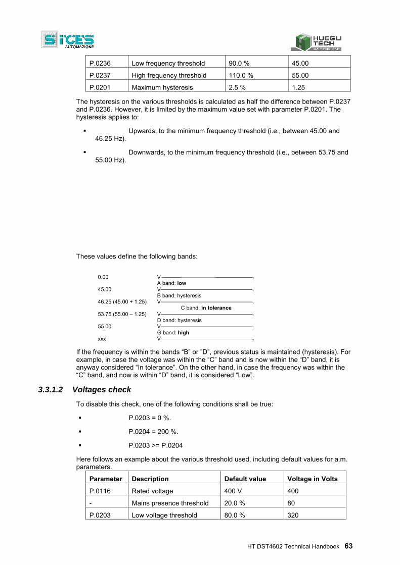
HT DST4602 Technical Handbook 63
P.0236 Low frequency threshold 90.0 % 45.00
P.0237 High frequency threshold 110.0 % 55.00
P.0201 Maximum hysteresis 2.5 % 1.25
The hysteresis on the various thresholds is calculated as half the difference between P.0237 and P.0236. However, it is limited by the maximum value set with parameter P.0201. The hysteresis applies to:
Upwards, to the minimum frequency threshold (i.e., between 45.00 and 46.25 Hz).
Downwards, to the minimum frequency threshold (i.e., between 53.75 and 55.00 Hz).
These values define the following bands:
0.00 V .
A band: low 45.00 V .
B band: hysteresis 46.25 (45.00 + 1.25) V .
C band: in tolerance 53.75 (55.00 – 1.25) V .
D band: hysteresis 55.00 V .
G band: high xxx V .
If the frequency is within the bands “B” or ”D”, previous status is maintained (hysteresis). For example, in case the voltage was within the “C” band and is now within the “D” band, it is anyway considered “In tolerance”. On the other hand, in case the frequency was within the “C” band, and now is within “D” band, it is considered “Low”.
3.3.1.2 Voltages check
To disable this check, one of the following conditions shall be true:
P.0203 = 0 %.
P.0204 = 200 %.
P.0203 >= P.0204
Here follows an example about the various threshold used, including default values for a.m. parameters.
Parameter Description Default value Voltage in Volts
P.0116 Rated voltage 400 V 400
- Mains presence threshold 20.0 % 80
P.0203 Low voltage threshold 80.0 % 320
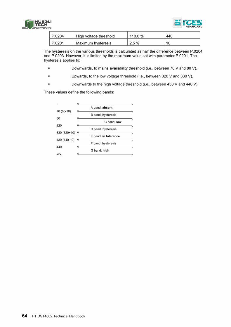
64 HT DST4602 Technical Handbook
P.0204 High voltage threshold 110.0 % 440
P.0201 Maximum hysteresis 2.5 % 10
The hysteresis on the various thresholds is calculated as half the difference between P.0204 and P.0203. However, it is limited by the maximum value set with parameter P.0201. The hysteresis applies to:
Downwards, to mains availability threshold (i.e., between 70 V and 80 V).
Upwards, to the low voltage threshold (i.e., between 320 V and 330 V).
Downwards to the high voltage threshold (i.e., between 430 V and 440 V).
These values define the following bands:
0 V .
A band: absent 70 (80-10) V .
B band: hysteresis 80 V .
C band: low 320 V .
D band: hysteresis 330 (320+10) V .
E band: in tolerance 430 (440-10) V .
F band: hysteresis 440 V .
G band: high xxx V .
HT DST4602 Technical Handbook 65
If the voltage is in the “B”,”D” or ”F” bands, previous status is maintained (hysteresis). For example, if the voltage was in the “E” band and now it is in “D” band, it is considered however “In tolerance”. On the contrary, if voltage was in the “C” band and now is in “D” band, it is considered “Low”.
Such status are managed at individual phase level.
3.3.1.3 Unbalance check
In three-phases systems, the mains can be 'out of tolerance' in case the absolute value of the three phase-to-phase voltages differs more than the set threshold.
To disable this check, simply set parameter P.0238 to zero.
Here follows an example about the various threshold used, including default values for a.m. parameters.
Parameter Description Default value Voltage in Volts
P.0116 Rated voltage 400 V 400
P.0238 Mains unbalance threshold 10.0 % 40
In case the absolute value of two phase-to-phase voltages differs more than 40 V, the mains is seen as out of tolerance (the MAINS LIVE lamp flashes with 25% on). In case the absolute values of all phase-to-phase voltages are lower than 40 V, the mains is seen in tolerance. No hysteresis is managed for this check.
3.3.1.4 Rotation direction check
For three-phases systems mains can be 'out of tolerance' in case the rotation direction of the three phase-to-phase voltages differs from the specification set with parameter P.0239.
To disable this check, simply set parameter P.0239 to zero.
In case a “clockwise” rotation direction is required, please set “1” in P.0239; in case the rotation direction is “counter-clockwise”, the mains is seen as 'Out of tolerance' (the MAINS LIVE lamp flashes with 25% on).
In case a “counter-clockwise rotation direction is required, please set “2” in P.0239; in case the rotation direction is “clockwise”, the mains is seen as out of tolerance (the MAINS LIVE lamp flashes with 25% on).
3.3.1.5 Internal sensor status
In order to diagnose the mains “global” status, the following algorithms are used, shown in their computing order:
In case the status of all existing voltages (1 or 3) and the frequency are “Absent”, also the global status is “Absent” .
In case the status of all existing voltages (1 or 3) and the frequency is “In tolerance”, also the global status is “In tolerance”.
In case the status of at least one voltage or the frequency is “High”, also the global status is “High”.
In case none of the previous conditions occurs, global status is “Low”.
In case the tests show that the mains is “In tolerance”, perform also the following tests:
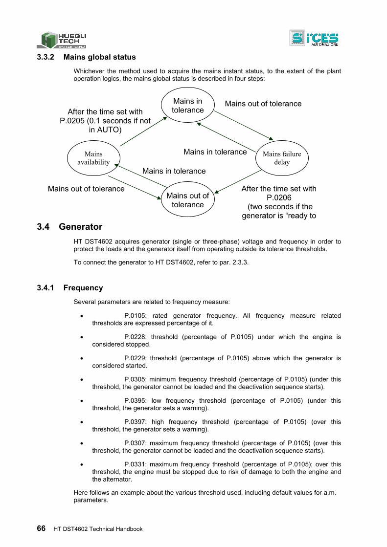
66 HT DST4602 Technical Handbook
3.3.2 Mains global status
Whichever the method used to acquire the mains instant status, to the extent of the plant operation logics, the mains global status is described in four steps:
3.4 Generator
HT DST4602 acquires generator (single or three-phase) voltage and frequency in order to protect the loads and the generator itself from operating outside its tolerance thresholds.
To connect the generator to HT DST4602, refer to par. 2.3.3.
3.4.1 Frequency
Several parameters are related to frequency measure:
P.0105: rated generator frequency. All frequency measure related thresholds are expressed percentage of it.
P.0228: threshold (percentage of P.0105) under which the engine is considered stopped.
P.0229: threshold (percentage of P.0105) above which the generator is considered started.
P.0305: minimum frequency threshold (percentage of P.0105) (under this threshold, the generator cannot be loaded and the deactivation sequence starts).
P.0395: low frequency threshold (percentage of P.0105) (under this threshold, the generator sets a warning).
P.0397: high frequency threshold (percentage of P.0105) (over this threshold, the generator sets a warning).
P.0307: maximum frequency threshold (percentage of P.0105) (over this threshold, the generator cannot be loaded and the deactivation sequence starts).
P.0331: maximum frequency threshold (percentage of P.0105); over this threshold, the engine must be stopped due to risk of damage to both the engine and the alternator.
Here follows an example about the various threshold used, including default values for a.m. parameters.
Mains in tolerance
Mains availability
Mains failure delay
Mains out of tolerance
Mains out of tolerance
Mains in tolerance
Mains out of tolerance
Mains in tolerance
After the time set with P.0206
(two seconds if the generator is “ready to
After the time set with P.0205 (0.1 seconds if not
in AUTO)
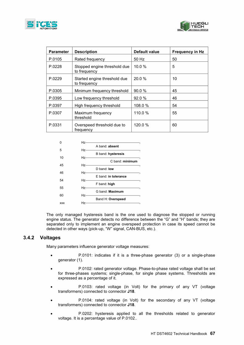
HT DST4602 Technical Handbook 67
Parameter Description Default value Frequency in Hz
P.0105 Rated frequency 50 Hz 50
P.0228 Stopped engine threshold due to frequency
10.0 % 5
P.0229 Started engine threshold due to frequency
20.0 % 10
P.0305 Minimum frequency threshold 90.0 % 45
P.0395 Low frequency threshold 92.0 % 46
P.0397 High frequency threshold 108.0 % 54
P.0307 Maximum frequency threshold
110.0 % 55
P.0331 Overspeed threshold due to frequency
120.0 % 60
0 Hz .
A band: absent 5 Hz .
B band: hysteresis 10 Hz .
C band: minimum 45 Hz .
D band: low 46 Hz .
E band: in tolerance 54 Hz .
F band: high 55 Hz .
G band: Maximum 60 Hz .
Band H: Overspeed xxx Hz .
The only managed hysteresis band is the one used to diagnose the stopped or running engine status. The generator detects no difference between the “G” and “H” bands; they are separated only to implement an engine overspeed protection in case its speed cannot be detected in other ways (pick-up, “W” signal, CAN-BUS, etc.).
3.4.2 Voltages
Many parameters influence generator voltage measures:
P.0101: indicates if it is a three-phase generator (3) or a single-phase generator (1).
P.0102: rated generator voltage. Phase-to-phase rated voltage shall be set for three-phases systems; single-phase, for single phase systems. Thresholds are expressed as a percentage of it.
P.0103: rated voltage (in Volt) for the primary of any VT (voltage transformers) connected to connector J18.
P.0104: rated voltage (in Volt) for the secondary of any VT (voltage transformers) connected to connector J18.
P.0202: hysteresis applied to all the thresholds related to generator voltage. It is a percentage value of P.0102..
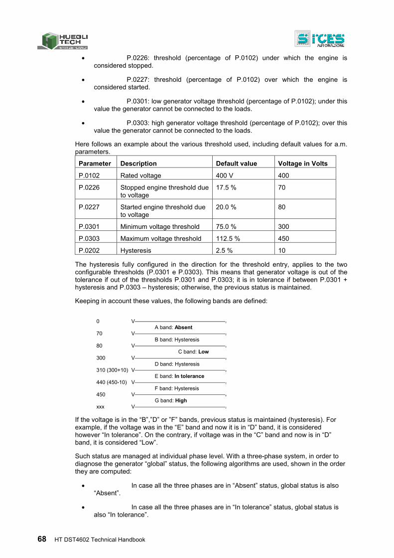
68 HT DST4602 Technical Handbook
P.0226: threshold (percentage of P.0102) under which the engine is considered stopped.
P.0227: threshold (percentage of P.0102) over which the engine is considered started.
P.0301: low generator voltage threshold (percentage of P.0102); under this value the generator cannot be connected to the loads.
P.0303: high generator voltage threshold (percentage of P.0102); over this value the generator cannot be connected to the loads.
Here follows an example about the various threshold used, including default values for a.m. parameters.
Parameter Description Default value Voltage in Volts
P.0102 Rated voltage 400 V 400
P.0226 Stopped engine threshold due to voltage
17.5 % 70
P.0227 Started engine threshold due to voltage
20.0 % 80
P.0301 Minimum voltage threshold 75.0 % 300
P.0303 Maximum voltage threshold 112.5 % 450
P.0202 Hysteresis 2.5 % 10
The hysteresis fully configured in the direction for the threshold entry, applies to the two configurable thresholds (P.0301 e P.0303). This means that generator voltage is out of the tolerance if out of the thresholds P.0301 and P.0303; it is in tolerance if between P.0301 + hysteresis and P.0303 – hysteresis; otherwise, the previous status is maintained.
Keeping in account these values, the following bands are defined:
0 V .
A band: Absent 70 V .
B band: Hysteresis 80 V .
C band: Low 300 V .
D band: Hysteresis 310 (300+10) V .
E band: In tolerance 440 (450-10) V .
F band: Hysteresis 450 V .
G band: High xxx V .
If the voltage is in the “B”,”D” or ”F” bands, previous status is maintained (hysteresis). For example, if the voltage was in the “E” band and now it is in “D” band, it is considered however “In tolerance”. On the contrary, if voltage was in the “C” band and now is in “D” band, it is considered “Low”.
Such status are managed at individual phase level. With a three-phase system, in order to diagnose the generator “global” status, the following algorithms are used, shown in the order they are computed:
In case all the three phases are in “Absent” status, global status is also “Absent”.
In case all the three phases are in “In tolerance” status, global status is also “In tolerance”.
HT DST4602 Technical Handbook 69
In case at least one phase is in “High” status, global status is also “High”.
In case none of the previous conditions occurs, global status is “Low”.
Thresholds P.0301 and P.0303 are used also to manage the generator protections on voltage. These protections can be individually disabled setting to zero the relevant parameter that specifies the delay (respectively P.0302 and P.0304). Thresholds are however used in order to define voltage status: this allows not to switch the loads on the generator if the electrical magnitudes are out of the tolerance band, even though protections are disabled.
3.4.3 Overview
For general management purposes, generator operation can be described in three steps:
a) Steady out of tolerance: the generator voltages and/or frequency status must be continuously other than “In tolerance” for two seconds. The “GENERATOR LIVE” lamp is Off if voltages and frequency are in “Absent” status, otherwise it blinks.
b) Steady present: generator's voltages and frequency status must be fully “in tolerance” for at least 0.5 seconds. “GENERATOR LIVE” lamp is steady On.
Transient: shifting from status “a” to status “b” or vice versa. The “GENERATOR LIVE”lamp blinks. On the front panel only status “a”, “b”, and “c” are displayed, by means of the “GENERATOR LIVE” lamp. Global and individual voltage phases and frequency “Absent” status etc. are not shown: however, they can be read with ModBus protocol via the serial port.
3.5 Inhibition
In AUTO mode, whatever the kind of plant and the Mains/Bus status, two causes can anyway inhibit the gen-set:
operational time range.
digital input.
The “INHIBIT” lamp turns On when an inhibition is active. Note: the inhibition status does not affect TEST and REMOTE START modes.
3.5.1 Inhibition from contact
The controller can use a digital input programmed for inhibiting the gen-set automatic operation (function “2501” - gen-set operation inhibit).In case of an “active” input, the engine is never automatically started, not even if the plants condition require.
Use parameter P.0207 to set a delay between input's physical activation and this function's logic activation: however, the delay can only be applied to a controller in AUTO mode, otherwise the delay is nil.
Use parameter P.0208 to set a delay between input's physical de-activation and this function's logic de-activation: in case the generator is already running, the delay is two seconds (firm).
70 HT DST4602 Technical Handbook
INFORMATION! When a function with value 2501 is coupled with a digital input, acquisition of this input depends on the time set in P.0207 and/or P.0208; the acquisition time related to the digital input is skipped.
3.5.2 Inhibition from clock
Using parameters P.0421, P.0422 and P.0423, it is possible to define on a weekly basis the hourly operation ranges. In particular, parameter P.0421 allows to set the generator's weekly operation days. The remaining two allow to set an hour range valid for all selected days. The range start time (P.0422) refers to the days set in P.0421, while the range end time (P.0423) refers to the same day, if its value is higher than P.0422, or to the following day if lower (across midnight). Moreover, setting P.0422 and P.0423 to the same value defines a full day's range.
3.5.3 Inhibition due to load function
In multiple generator parallel plants it is possible to use the “load function”. This function only activates the generators needed to meet the power required by loads in specific times. That is, exceeding generators are stopped even though, for example, it is an emergency plant and mains is Off.
3.5.4 Inhibition due to mains failure
In mains parallel plants, where non local loads require power, the generator only works in parallel to the mains. In case of mains failure, after a configurable waiting time (P.0899), the HT DST4602 stops the generator until the mains is back “in tolerance”.
3.5.5 Inhibition due to “GCB switch not open”
In multiple generator parallel plants, a generator's GCB switch might not open when the generator is stopped.
This is an hazardous situation, as the voltage from the other running generators 'drags' the alternator of the gen-set with “not open GCB”. In this condition, notwithstanding the stop command, the engine would keep running with all external services unpowered (oil pumps and the like).
When at least one generator in the PMCB bus is in “GCB not open” status, it is possible to prevent closing the GCBs of the other generators (and even forcing the opening in case they are closed): in this case, the generators are stopped waiting for the problem to be fixed.
3.6 Mains Simulation
Function 3101 of HT DST4602 – Mains external sensor - differs from function 2501 - Inhibition.
At the input, with the function assigned, a generic mains external sensor may be connected as an alternative to the internal one; therefore, two parameters may be used to provide the timing required to check whether the external mains is absent or present. These parameters are P.0205 for delayed 'mains available' detection and P.0206 for delayed 'mains failure' detection.
To use this input, ensure to deactivate the internal mains sensor by setting parameter P.0116 to zero.
MAINS SIMULATION status is:
HT DST4602 Technical Handbook 71
a) Not active: the input is not continuously active for the time set with P.0206 (if the generator is not ready to supply, otherwise for two seconds).
b) Active: the input is continuously active for the time set with P.0205 (if the key switch is in AUTO, otherwise immediately).
c) Transient: shifting from status “a” to status “b” or vice versa.
3.6.1 Differences between Mains Simulation and Inhibition
The two functions provide different operation logics and purpose. The first one emulates the internal sensor, while the second one is specifically used for preventing system startup, whatever the mains status. In this way, status indication is more coherent with the real status of the system.
Moreover, in applications that use the reverse synchronization function, Mains Simulation activates the reverse synchronization while Inhibition leads to the generator stop sequence.
3.7 Engine
HT DST4602 can start, stop and protect the engine by means of a series of thresholds on the acquired measures (oil pressure, coolant temperature, speed etc.). Before describing engine management sequences, it is necessary to define in which way the controller determines the engine running status.
3.7.1 Engine running/stopped status acknowledgement
There are six possible ways to define whether the engine is running or not:
1. Engine speed higher than threshold P.0225 Running engine threshold (rpm). This check is not used in case said threshold, or threshold P.0224 Stopped engine threshold (rpm) are set to zero, or measure unavailable (parameters P.0110 Pick-up rim teeth q.ty and P.0111 Rpm/W ratio set to zero, plus CANBUS (ECU-Engine Control Unit) not used).
2. Voltage of signal D+ from the battery-charger is over the threshold set with parameter P.0230 (D+) stopped engine threshold. This check is not used in case said threshold, or threshold P.0231 (D+) Running engine threshold are set to zero, or measure unavailable. Parameter P.4041 is set to: 1300-D+ Signal.
3. If the low/minimum oil pressure inputs are not active. This parameter is not used in case parameter P.0232 is set to zero (i.e. if specifically set to non use) or non digital input is set for low/minimum pressure contact acquisition.
4. In case the voltage measured on at least one phase of the generator is higher than the threshold P.0227 (V) Running engine threshold. This check is not used in case said threshold, or threshold P.0226 (V) Stopped engine threshold are set to zero.
5. In case the frequency measured on generator is higher than the threshold P.0229 Running engine threshold (Hz). This check is not used in case said threshold, or threshold P.0228 Stopped engine threshold (Hz) are set to zero.
6. In case the engine signals a 'running' status on CANBUS (ECU Interface).
72 HT DST4602 Technical Handbook
To acknowledge engine running status, at least one of the previous conditions must be continuously present for at least 0.2 seconds. The controller disables the starter command (and prevents other activations) if it detects the engine running.
In the same way the conditions to acknowledge the stopped engine status are:
1 Engine speed lower than threshold P.0224 Stopped engine threshold (rpm). This check is not used in case said threshold, or threshold P.0225 Running engine threshold (rpm) are set to zero, or measure unavailable (P.110 Pick-up rim teeth q.ty and P.0111 Rpm/W ratio set to zero).
2 Voltage of battery-charger signal D+ lower than threshold set with parameter P.0231 Running engine threshold (D+). This check is not used in case said threshold, or threshold P.0230 Stopped engine threshold (D+) are set to zero. Parameter P.4041 is set other than: 1300-D+ Signal.
3 In case low/minimum oil pressure contacts are active. This check is not used in case parameter P.0232 is set to zero (i.e. if specifically set to non use) or no digital input is set for low/minimum pressure contact acquisition.
7. In case the voltage measured on at least one generator phase is lower than threshold P.0226 Stopped engine threshold (V) set to zero. This check is not used in case said threshold, or threshold P.0227 Running engine threshold (V) are set to zero.
4 In case the frequency detected on generator is set to threshold P.0228 Stopped engine threshold (Hz). This check is not used in case said threshold or threshold P.0229 Running engine threshold (Hz) are set to zero.
5 In case the engine signals a 'stopped' status on CANBUS (ECU Interface).
The engine is considered stopped if all the previous conditions are met (all the enabled ones) continuously for five seconds.
3.7.2 Engine commands
The controller can manage seven different commands for engine management:
START: command for the starter.
FUEL: command for the fuel solenoid valve.
STOP: stop command when energized.
PREHEAT: command for Diesel engines glow-plugs preheating.
PRELUBRICATION: engines pre-lubrication command.
GAS: command for the gas valve (for gas engines).
IDLE: command to activate engine idle speed.
ENABLE ENGINE: this command is activated together with the FUEL command, but can be deactivated before the FUEL command (useful for electronic engines shutdown without causing any vacuum in the fuel pipes).
All controller's digital outputs, either change-over-contact or open-collector, can be configured from OUTPUT 1 to OUTPUT 16 and may be assigned to the commands START and FUEL. Normally, said outputs are assigned, after configuration, to the outputs OUTPUT 5 and OUTPUT 6. These outputs, featuring overcurrent protection, consist of relays (4 A) that, when active, provide the output for the voltage supplied on terminal 6 of J5.
HT DST4602 Technical Handbook 73
As the other five commands are optional, dedicated outputs are not available. However, you may associate any of these commands to any output from OUTPUT 1 to OUTPUT 16. When configuring the controller, ensure to pay attention to output types: connector J26 consists of open-collector transistor outputs that, when active, connect the terminal to the battery negative (otherwise floating); outputs of connector J5 from OUTPUT1 and OUTPUT2 are 1 A relays; outputs OUTPUT3 and OUTPUT4 are 4 A relays. When active, these outputs refer to input voltage at terminal 1 and 6 of J5. Configuration is possible with parameters from P.3001 to P.3016 (menu 1 System, 1.7 digital Inputs/Outputs, 1.7.3 digital Outputs, 1.7.3.1 digital Outputs) using the following values:
1001: glow-plugs preheating (PREHEAT).
1004: gas valve (GAS).
1006: stop command when energized (STOP).
1007: low speed command (IDLE).
1002: engine control unit enable (ENABLE ENGINE)
1033: pre-lubrication command
By default, commands for glow-plugs preheating, gas valve, idle and enable engine, are not used, whereas the stop command when energized is associated to the output OUTPUT 4 of terminal 5 of connector J5.
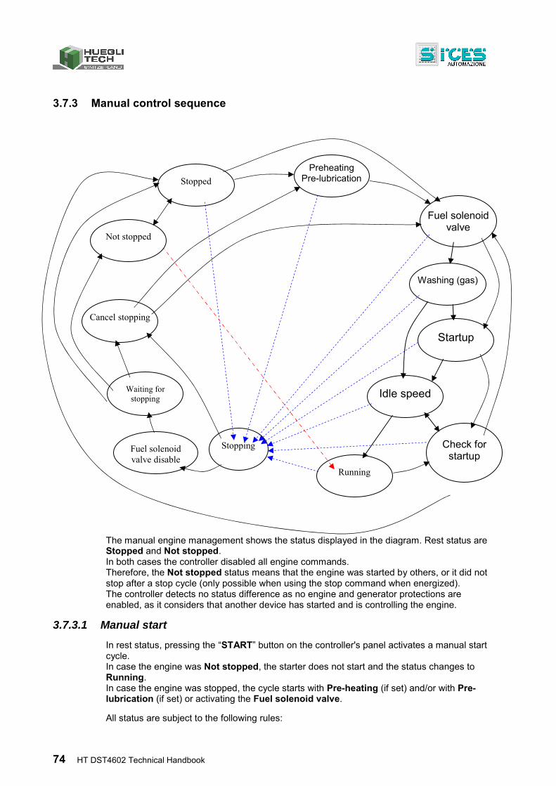
74 HT DST4602 Technical Handbook
3.7.3 Manual control sequence
The manual engine management shows the status displayed in the diagram. Rest status are Stopped and Not stopped. In both cases the controller disabled all engine commands. Therefore, the Not stopped status means that the engine was started by others, or it did not stop after a stop cycle (only possible when using the stop command when energized). The controller detects no status difference as no engine and generator protections are enabled, as it considers that another device has started and is controlling the engine.
3.7.3.1 Manual start
In rest status, pressing the “START” button on the controller's panel activates a manual start cycle. In case the engine was Not stopped, the starter does not start and the status changes to Running. In case the engine was stopped, the cycle starts with Pre-heating (if set) and/or with Pre-lubrication (if set) or activating the Fuel solenoid valve.
All status are subject to the following rules:
Preheating Pre-lubrication Stopped
Fuel solenoid valve
Check for startup
Not stopped
Stopping
Startup
Running
Waiting for stopping
Cancel stopping
Washing (gas)
Idle speed
Fuel solenoid valve disable
HT DST4602 Technical Handbook 75
if a stop request occurs, controller shifts to Stopping status.
if the “START” button is released, next status is Check for startup.
If the engine running status is detected, next status is Idle speed (if configured) or Running.
The Pre-heating cycle is performed if parameter P.0209 pre-heating cycle in seconds is set other than zero and no outputs are configured for GAS engine washing (GAS valve). In fact, parameter P.0209 is shared with preheating cycle and washing cycle (so they are performed in alternative).
It is also possible to configure a digital output for Pre-lubrication assigning the output parameter the value 1033. The activation time for this output is parameter P.0242. Pre-lubrication is managed in a secondary mode with respect to pre-heating, as pre-lubrication time - if pre-heating is set - is equal to or lower than pre-heating time. Configuring an output as pre-heating command is not mandatory. After this phase is completed, the engine is started. In this status, the commands FUEL, ENABLE ENGINE and PREHEAT are active; this allows to use it even if the pre-heating command is not used, to slightly increase the delay between the commands FUEL and START.
The Fuel solenoid valve status is performed in alternative to pre-heating, in order to ensure a minimum 0.2 seconds delay between the commands FUEL and P.0420 Test start duration, ENGINE and the command START. This step is required as some fuel solenoid valves can have a mechanical problem that, in case of fuel flowing during the opening, prevents the opening due to vacuum on the valve's flange. Next status are engine start or, if configured, washing cycle. In this status the commands FUEL, ENABLE ENGINE and IDLE are active.
The Washing cycle is only used for gas engines. It consists in the activation of the starter keeping closed the GAS valve. In this way a vacuum is created, which extracts the residual gases before starting the engine. The cycle is performed if at least one output is configured for GAS valve command; the duration is configured with parameter P.0209 Pre-heating cycle duration in seconds (shared with the pre-heating cycle). When the configured time is over, the engine starts cranking. In this status, the commands FUEL, ENABLE ENGINE, IDLE and STARTare active.
During the Startup, the commands FUEL, ENABLE ENGINE, IDLE and START are active. This phase lasts until the engine running status is acknowledged or until the “START” button is released. The engine running status is continuously watched (refer previous paragraphs) in order to release the starter as soon as possible. The cycle ends when the “START” button is released or the engine starts up (see notes at the beginning).
The Check for startup status is entered when the “START” button is released before the controller acknowledges the engine running status. Actually, the given command should be enough for the engine to start. In this status the engine is checked for a maximum time of 10 seconds, to verify the startup. The commands FUEL, ENABLE ENGINE and GAS are active (to ease the engine startup). If the engine starts up, Running status will follow, otherwise the controller reverts to Stopped status after ten seconds. If the “START” button is pressed during this phase, the startup procedure is repeated, by-passing the pre-heating phase (from Fuel solenoid valve status).
The Low speed status is performed in case parameter P.0233 Low speed cycle duration is other than 0. In this status the commands FUEL, ENABLE ENGINE, IDLE and GAS are active. If the controller is connected to the engine via CANBUS (ECU Interface), the idle speed command is directly managed over the bus. If not, setting another output for this command is required. The cycle ends when the set time is over. In case the controller acquires coolant temperature (via CANBUS or sensor), a minimum temperature threshold (P.0223 minimum temperature threshold for enabling supply) can be set to end the
76 HT DST4602 Technical Handbook
cycle: if the coolant temperature is continuously higher than this threshold for two seconds, the idle cycle ends. When the previous cycle is over, next status is Running.
In Running status, the commands FUEL, ENABLE ENGINE and GASare active.
3.7.3.2 Manual stop
From Running status (but also from any other status described in the previous paragraph) the controller shifts to Stopping status in the following cases: With a command from serial port (also via SMS).
Pressing the “STOP” button on the controller's panel.
When an alarm, deactivation or unload occurs.
INFORMATION! The stopping phase can be also performed with engine already stopped .
During the Stopping phase the commands ENABLE ENGINE, GAS, START, PRE-LUBRICATION and PREHEAT are disabled while the STOP command is activated. The command FUEL is disabled after a time period set with parameter P.0234 STOP/FUEL commands delay. This step is required in order to prevent the stopping engine from creating a vacuum in the fuel pipes, that could lead to the solenoid valve jamming at the next opening command. The duration of this phase is set with parameter P.0213 stop command duration when energized. When the set time is over, the controller shifts to Waiting for stopping status.
During the Waiting for stopping phase, all engine commands are disabled and controller waits for the engine to stop. The duration of this phase is set with parameter P.0214 stopping cycle duration, minus the time set with P.0213 stop command duration when energized. At the end of this phase, if the engine is not stopped the controller shifts to Not stopped status. If the engine stops, the controller reverts to Stopped status. The complete phase Awaiting stop can be disabled by setting time in parameter P.0214 stop cycle duration to zero.
In case during the last two phases all stop requests cease and “START” is pressed again, the controller shifts to Cancel stopping even though the engine has not been already diagnosed as stopped. In fact, it is possible to end one stop cycle if the controller is in MAN mode.
The phase Cancel stopping is only used to allow some delay between the deactivation of any STOP command and the activation of the FUELcommand. This is a 0.2 seconds delay, at the end of which the controller reverts to Stopped status; from this point the controller will perform engine startup, provided the status is OK.
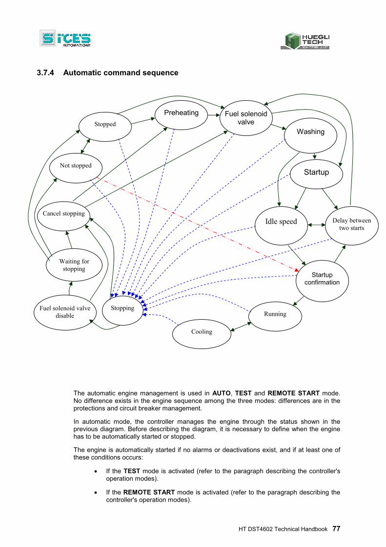
HT DST4602 Technical Handbook 77
3.7.4 Automatic command sequence
The automatic engine management is used in AUTO, TEST and REMOTE START mode. No difference exists in the engine sequence among the three modes: differences are in the protections and circuit breaker management.
In automatic mode, the controller manages the engine through the status shown in the previous diagram. Before describing the diagram, it is necessary to define when the engine has to be automatically started or stopped.
The engine is automatically started if no alarms or deactivations exist, and if at least one of these conditions occurs:
If the TEST mode is activated (refer to the paragraph describing the controller's operation modes).
If the REMOTE START mode is activated (refer to the paragraph describing the controller's operation modes).
Preheating
Stopped
Fuel solenoid valve
Startup confirmation
Not stopped
Stopping
Startup
Running
Waiting for stopping
Cancel stopping Delay between
two starts
Cooling
Washing
Idle speed
Fuel solenoid valve disable
78 HT DST4602 Technical Handbook
In case an automatic startup is required, and no startup inhibition active, neither from contact nor from watch/calendar. There are several different causes requiring an automatic startup which depend on the plant type.
o For SSB systems: in case mains voltage is out of tolerance (from internal or external mains sensor).
o For multiple parallel generator systems: if using the generator is required due to load function logics.
In automatic mode, the engine can be stopped in two ways:
a) With normal procedure. This procedure consists in an engine coolant cycle (only if the load is connected to the generator) with the engine running and the loads connected to the mains. This procedure applies if:
o No automatic startup request is pending (see above)
o An anomaly, qualified as “deactivation” occurred (it is an anomaly typically dangerous for loads but not for the gen-set).
NOTE: if the plant type allows, this stop procedure also performs power unload.
b) With an emergency procedure. This procedure requires immediate engine stop, without engine cooling cycle. It applies if:
o The key switch is turned on OFF/RESET
An anomaly defined as “alarm” has occurred and the engine is in a status other than Stopped or Non stopped.
INFORMATION! In automatic mode, the stop commands from panel (STOP button), from serial port and from SMS are included in this category since they activate the alarm A07 (manual stop in auto mode).
To describe the diagram, assume the Stopped and Not stopped status as starting point. In both status, engine commands are stopped. Therefore, the Not stopped status means that the engine was started by others, or it did not stop after a stop cycle (only possible when using the stop command when energized). The controller detects no status difference as no engine and generator protections are enabled, as it considers that another device has started and is controlling the engine. Exiting this status is only possible in case of a request for automatic startup or stop.
3.7.4.1 Automatic startup
From rest status, if so requested, the startup procedure activates, possibly performing the Pre-heating cycle or enabling the commands FUEL and ENABLE ENGINE and then START. If the start request is activated with the engine in a Not stopped condition, the controller shifts directly to Start confirmation status.
All status are subject to the following rules:
if a stop request occurs, controller shifts to Stopping status.
if the start request ends, controller shifts to Stopping status.
If the engine running status is detected, next status is Idle speed (if configured) or Running.
HT DST4602 Technical Handbook 79
For Preheat, Fuel solenoid, Washing, Start and Idle speed status refer to manual startup procedure. Only difference is that the maximum duration of the Start status can be set with the parameter P.0210 Startup command duration.
Compared to manual start, two new status are introduced.
The Start confirmation status is performed when the Idle speed cycle ends, or anyway after the engine is acknowledged as running. This status is used to wait until the generator reaches its operating conditions. In effect, the engine could shutdown (the controller might have acknowledged it as running only because the starter is providing enough speed). In these cases, the controller will try again to start the engine, until the end of the configured attempts. From this status the controller shifts to Running if the generator reaches its operating conditions (in this case the startup was successful and a subsequent stop of the engine indicates a serious gen-set malfunction); the controller then shifts to Delay between two starts status if the engine stops and to the Stopping status if the engine did not actually stop but the generator did not reach its operating conditions within the time set with parameter P.0217 Maximum time for operating conditions (the alarm A008 – “operating conditions not reached” activates). In this status, the commands FUEL, ENABLE ENGINE and GAS are active.
The status Delay between two starts is performed each time the engine does not start after an automatic startup attempt. The duration of this status is set with parameter P.0212 Delay between two startups. At the end the controller shifts to Startup status. This status has been performed for the number of times set with parameter P.0211 Number of startup attempts: in case after all the set attempts the engine did not start, the controller activates the alarm A022 – “Overcrank” and shifts to Stop status. In this status, the commands FUEL, ENABLE ENGINE and PREHEAT are active, allowing to use it for pre-heating Diesel engines glow-plugs.
The starting procedure ends with the Running status. In this phase, loads change-over is enabled. In this phase the commands FUEL, ENABLE ENGINE and GAS are active.
3.7.4.2 Using two battery sets
The controller can control engine startups alternately managing two battery sets in order to ensure engine startups. To perform this procedure use the following digital output functions:
“1008 - select battery 1”.
“1009 - select battery 2”.
To use this function requires at least one output configured with function 1009. In this case, the startup sequence is the following.
Output “Select battery 1” enabled, output “Select battery 2” disabled.
2 seconds delay (may be increased with glow plugs pre-heating).
First startup attempt.
Pause
…...
Last startup attempt.
2 seconds delay
Output “Select battery 1” disabled, output “Select battery 2” disabled.
2 seconds delay
Output “Select battery 1” disabled, output “Select battery 2” enabled.
80 HT DST4602 Technical Handbook
2 seconds delay (may be increased by increasing delay between two startups).
First startup attempt with the second battery.
Pause
…...
Last startup attempt with the second battery.
Failed startup alarm.
2 seconds delay.
Output “Select battery 1” disabled, output “Select battery 2” disabled.
If the engine starts up, the sequence ends. The output “Select battery n” active in that moment is disabled after a 2 seconds delay after detecting started engine. In case no output is configured with function 1009, only the standard startup sequence will be performed. If, in this case, function 1008 is already assigned, the startup sequence starts by enabling the output with this function.
3.7.4.3 Standard automatic stop
In case plant type and conditions allow, the standard stop procedure requires unloading power first. An engine Cooling cycle is performed (during which the controller disconnects the generator from loads and/or parallel bars). This cycle is performed only if during the Running status the loads were changed-over on generator. During this cycle, the commands FUEL, ENABLE ENGINE and GAS are active. Cycle duration can be set with parameter P.0215 Cooling cycle duration. From this status it is possible to revert to Running status if stop requests cease and at least one startup requests exists (for example, the controller was in this status after mains is reactivated, yet mains fails again during this status). The cycle can be interrupted also if an emergency stop request occurs (an alarm or the key switched to OFF). In this case, or at the end of the time set with P.0215 Cooling cycle duration, the emergency stop cycle is activated.
3.7.4.4 Automatic emergency stop
The emergency stop procedure consists in stopping the engine without performing the cooling cycle. This procedure is common also in the standard stop, after the cooling cycle. During the Stopping phase the commands ENABLE ENGINE, GAS, START, PRE-LUBRICATION and PREHEAT are disabled; the STOP command is now active. The command FUEL is disabled after a time set with parameter P.0234 Delay between the commands STOP and FUEL. This step is required in order to prevent the stopping engine from creating a vacuum in the fuel pipes, that could lead to the solenoid valve jamming at the next opening command. The duration of this phase is set with parameter P.0213 stop command duration when energized. When the set time is over, the controller shifts to Waiting for stopping status. If during this phase all stop requests cease and at least one start request is present, the controller shifts to Cancel stopping status but only and uniquely if the engine was acknowledged as stopped. INFORMATION! In fact, it is not possible to interrupt an automatic stop cycle, as situations in the engine may cause difficult engine restarts, if not fully stopped.
During the Waiting for stopping phase, all engine commands are disabled and controller waits for the engine to stop. The duration of this phase is set with parameter P.0214 stopping cycle duration, minus the time set with P.0213 stop command duration. At the end of this phase, if the engine is still running, the alarm A021 – “engine not stopped” is activated and the controller shifts to Not stopped status. However, the whole phase Waiting for stopping (and also the alarm) can be disabled by setting to zero the parameter P.0214 stop cycle duration. If the engine stops, the controller reverts to Stopped status. This phase cannot be interrupted to perform more startups.
HT DST4602 Technical Handbook 81
The phase Cancel stopping is only used to allow some delay between the deactivation of any STOP command and the activation of the FUELcommand. This is a 0.2 seconds delay, at the end of which the controller reverts to Stopped status; from this point the controller will perform engine startup, provided the status is OK (and resetting to zero the startup attempts counter).
3.8 Breakers management
3.8.1 Power Breakers and change-over management
Usually, the outputs OUTPUT15 (GCB) and OUTPUT16 (MCB) of connector J4 are used for managing power change-over; these are two relays (250 V / 4 A) with exchanging contacts free of potential. The terminals 1, 2 and 3 of this connector are dedicated to the gen-set circuit breaker (GCB); the other three terminals 4, 5 and 6 are dedicated to the mains circuit breaker (MCB). It is possible to configure the controller to command two separated breakers or a power switch.
o Separated breakers. The “normally open” contact of the GCB shall be used for the command to change-over the loads to gen-set. The MCB “normally closed” contact must be used for mains loads closing command. In this way, with the controller not powered (and so with both the relays at rest) the loads are connected to mains. To use this function in SSB (Single Stand_By) application, the parameter P.0219 Contactor commands change time must be set to a proper value. This parameter is the minimum time required between opening of a breaker and closing of the other one. Two additional outputs can be used for breakers release coils management. the two functions are “2001 – Disable MCB release coil” and “2031 – Enable MCB release coil”. The breaker management logics depending on plant configuration are associated to this function. HT DST4602 logics prevent a non synchronized simultaneous closing of both GCB and MCB; however, an external protection logic, dependent upon the plant type, shall be used.
o Change-over switch (for SSB applications). The “normally open” contact of the GCB shall be used for the command to change-over the loads to gen-set. The change-over on mains is performed when this contact opens. To use this function, set the parameter P.0219 Contactors commands change time to zero, in order to avoid an useless wait during the change-over from gen-set to mains. In addition, the parameter P.0220 “Contactors command hold time” can be set: it will be not possible (neither in manual nor in automatic) to invert the power switch command until the time P.0220 “Contactors command hold time” since previous command is elapsed. This is useful because if the command is inverted during the movement phase, with some type of power switches it is possible that they lock themselves, and a manual action will be required to unlock them.
The panel lamps, named MCB and GCB, glow when the relevant breaker is closed and are switch off when it is open.
In some cases monitoring the actual breaker status is required. For this purpose it is possible to connect the status of one or both the breakers to the controller’s digital inputs. The breakers connection must be set in the controller (codes 3002 MCB switch status (Active Input if closed) and 3001 GCB switch status (Active Input if closed) in parameters P.2001…). Using this function, the actual status of the breakers is shown on the front panel:
o Lamp on: breaker closed.
o Lamp off: breaker open.
o Blinking lamp (during 25% of time): the controller sent the breaker a 'close' command, yet it is open.
82 HT DST4602 Technical Handbook
o Blinking lamp (during 75% of time): the controller sent the breaker an 'open' command, yet it is closed.
o Blinking lamp (during 50% of time) alternated to the BUS LIVE lamp: controller is in synchronizing mode.
In addition, if you set a time other than zero for the outputs to which are connected the breaker status (parameters P.2001…), the controller activates a warning in case the command and the status remain continuously conflicting for that time. Last, parameter P.0221 Enable output due to MCB closing failure allows to configure the controller for engine startup and to change-over loads on the generator in case of failed mains switch closure.
However, it is possible to connect also the status of only one breaker (if needed): the signalling of the command/status discrepancies and potential warnings will be managed only for this breaker.
WARNING! Ensure that controller configuration and set-up are compatible with the selected plant type.
3.8.2 Change-over logic
GCB command is activated only if all the following conditions are met:
o Generator voltages and frequency in tolerance for a proper time.
o The engine has been started by the controller (the fuel solenoid valve command must be active).
o No alarms or deactivations are present.
o The operation status depending on the operation mode and the selected plant type require
In OFF/RESET mode, GCB and MCB are at rest (at the same time, also “MCB Voltage Release Coil Disable” and “GCB Voltage Release Coil Enable” are at rest) allowing loads/BUS supply from mains.
In MAN mode, loads are normally switched to mains. You can manually command power change-over using the MCB and GCB buttons. Effective buttons functions depend on the selected plant type.
In AUTO mode and SSB applications, loads are changed-over on gen-set (provided the above conditions are met) only when mains is out of tolerance thresholds. As soon as mains comes back in tolerance (with proper times, see mains sequence), loads are newly changed-over on mains. The only exception is the MCB not closed warning: if properly configured, the controller changes-over to gen-set also with mains present. Shifting from any other operation mode to AUTO, loads are forced as described, driving a change-over if needed. This status uses another timing: to command closing GCB (Ig) is only possible after the time P.0218 “First output delay “ since the gen-set startup - even better, since the gen-set measures entered tolerance range - has elapsed.
In TEST mode, loads are normally changed-over to mains. Using the parameter “P.0222 Test load enable”, it is possible to enable the TEST Load mode that starts the change-over, or the closure in parallel, depending on the plant type and configuration. Commands MCB and GCB are active also during TEST mode, allowing to manually manage the gen-set load depending on the selected plant type.
Please note that the controller automatically shifts to AUTO (aborting TEST mode) in case automatic intervention is required.
In REMOTE START mode the generator is automatically connected to loads according to the plant type mode. All AUTO timings are valid. Please note that the controller automatically
HT DST4602 Technical Handbook 83
shifts to AUTO (aborting TEST mode) in case automatic intervention is required (mains failure).
4. Anomalies This chapter describes all the anomalies managed by the controller. Some of these act as protections for the loads, for the generator or for the engine. There is also signaling of specific events in the plant management. Before describing them in detail, some definitions are required.
Four types of anomalies are:
Warnings: these anomalies do not require shutting the engine down. They point out to situations that are not dangerous at the moment, but the operator must take some action because, if ignored, they could degenerate in one of the following categories.
Deactivations: these anomalies require shutting the engine down. They create hazards for the loads but not immediately for the engine. For this reason the engine can be stopped with the standard procedure (with the cooling cycle). However, it is not possible to restart the engine until the anomaly has not been acknowledged.
Deactivations with power unloading: this anomalies are similar to standard deactivations. As they do not create problems for the loads and the gen-set, in parallel operations opening of the power connection is preferably performed after power unloading. This is performed by fast unloading ramp. However, it is not possible to restart the engine until the anomaly has not been acknowledged.
Alarms: these anomalies require shutting the engine down. They create hazards for the loads and/or for the engine and the generator. For this reason the engine must be stopped immediately, without the cooling cycle. It is not possible to restart the engine until the anomaly is acknowledged.
When an anomaly activates, the controller performs the following:
a) It activates the internal horn and, if configured, also the external one.
b) Prompts the page S.02 ANOMALIES on the multifunction display. This page shows the numeric code and the current language text related to all active anomalies.
c) The “WARNING” lamp starts blinking if the anomaly is a warnings; in the other cases (alarms, deactivations, and deactivations with unloading power ramp) the “ALARM” lamp starts blinking. The blinking status means that at least one anomaly is active and has not been yet acknowledged by the operator.
d) If the anomaly is not a warning, the controller disconnects the gen-set from loads or parallel bus bars and stops the engine (with or without the cooling cycle).
After an anomaly the operator has two choices:
a) Acknowledge it: this informs the controller that the operator has acknowledged the event.
b) Reset: this informs the controller that the anomaly is no longer active.
The operator can acknowledge the anomaly (sequence ISA2C) by pressing the ACK/TEST button. Pressing the button the first time only stops the acoustic signal; pressing a second time performs the acknowledgement and stops the blinking indicators “ALARM” and
84 HT DST4602 Technical Handbook
“WARNING”. However, horn management is associated to parameter P.0491 Horn duration:
o If set to zero, the horn will be never activated.
o If set to 999, the horn will be activated when a new anomaly arises, and will be deactivated when the operator presses the ACK/TEST button.
o If set to a value ranging from 1 to 998, the horn is enabled by any new anomaly and disabled by pressing the ACK/TEST button, or after the time in seconds assigned to parameter P.0491 Horn duration.
The multifunction display shows the anomaly until the operator “acknowledges” it, even if the relevant cause is no longer present.
The controller automatically resets all the acknowledged warnings when their cause is no longer active. However, to cancel deactivations and alarms, turn the key switch to “OFF/RESET” (after the problems causing deactivation and alarms have been fixed, to restore operation you must revert to MAN or AUTO mode). With this procedure, it is also possible to reset externally managed anomalies. You may configure one of the auxiliary outputs (code 3151 Anomalies reset in parameter P.3001... and following) in order to activate after a set time (1 second), when the internal anomalies reset sequence is performed. INFORMATION! Remember that the one second pulse is generated only for the reset procedure, not for the acknowledgement one.
An alarm can be activated only if no other alarms are already active (there are some exceptions to this rule and will be underlined in the rest of the paragraph). Some deactivations or warnings can be active.
A deactivation can be activated only if no alarms and deactivations are already active. Some warnings together with other Deactivations with power unloading can be active.
A deactivation with power unloading with unload power ramp can be activated only if no alarms, deactivations and deactivations with power unloading are already active. Some other warnings can be active.
A warning can be activated only if no alarms, deactivations and deactivations with power unloading are already active. Some other warnings can be active.
Here follows a detailed description of each anomaly.
The terms used are enable and activation:
Enabling an anomaly refers to the minimum conditions required for the controller to detect the relevant cause.
Activation of an anomaly refers to the cause after enabling.
INFORMATION! Normally, all protections are enabled if the engine is started by the controller, i.e. if the fuel solenoid valve command is active. If not, the only way to “enable” the protections is to force the controller to start the engine again (by pressing the START key in MAN), for example: the cranking motor will not be activated but the controller will act as having already performed the startup.
HT DST4602 Technical Handbook 85
4.1 Contact/analog Protection inputs
Some of these anomalies are acquired externally through digital inputs. Inputs can be assigned to the HT DST4602 controller and/or to the DITEL optional modules, if available.
In the example shown, and in the paragraph 5.2 ANOMALIES LIST, the digital input INPUT1 of the HT DST4602 controller is configured to acquire the anomaly. Related parameters: P.2001 Function of Input 1
P.2002 Delay for input 1
P.2001 P.2002 (for input 1 or equivalent for other inputs. Parameters 2001÷2598) To disable: P.2002=0
Active if the configured input remains continuously active for the associated time.
Analog inputs measures may also cause malfunctions, if so configured. Inputs can be assigned to the HT DST4602 controller and/or to the DITEMP (DITHERM/DIGRIN) and DIVIT optional modules, if available.
Protection is enabled only if one of the controller's analog inputs is configured to acquire the analog measure. If this measure is out of range because bigger than set thresholds, over acquisition time, the malfunction sequence configured in the parameter will occur. Related parameters: P.4001 Function of Input 1
P.4001 (for input 1 or equivalent for other inputs. Parameters 4001÷5475) To disable: Measure threshold acquisition time set to zero.
However, some of the controller's inputs, due to hardware configuration, are strictly connected to some type of measure sensors. The malfunctions list will show those inputs, set to sense common engine analog sensors measures.
Configurable parameters for digital inputs range from 2001 to 2598. Configurable parameters for analog inputs range from 4001 to 5482.
To find the input that originated the malfunction, please refer to digital/analog table in the document: SICES EAAM0380xx– HT DST4602, find the anomaly numeric code in the Alarm column: On the same line, you will find the input activating the anomaly and the relevant parameters.
86 HT DST4602 Technical Handbook
4.2 Anomalies list
01 – Minimum generator voltage
Type: Deactivation Category: Load protection Related parameters: P.0101 Number of phases of the generator
P.0102 Generator rated voltage P.0202 Generator measures hysteresis P.0301 Minimum voltage threshold P.0302 Minimum voltage delay
To disable: P.0302=0 Enabled in: MAN, AUTO, TEST, REMOTE START
Description:
Enabling: Engine started (fuel solenoid valve command activated). GCB closed. Generator voltage and frequency in tolerance.
Disabling: Engine startup and stop phase
Enabling: At least one of the generator voltages continuously below the threshold P.0301 for time P.0302.
02 – Maximum generator voltage
Type: Alarm Category: Load/generator protection Related parameters: P.0101 Number of generator phases
P.0102 Generator rated voltage P.0202 Generator measures hysteresis P.0303 Maximum voltage threshold P.0304 Maximum voltage delay
To disable: P.0304=0 Enabled in: MAN, AUTO, TEST, REMOTE START
Description:
Enabling: Engine started (fuel solenoid valve command activated). GCB closed. Generator voltage and frequency in tolerance.
Disabling: Engine startup and stop phase
Enabling: At least one of the generator voltages continuously below the threshold P.0303 for time P.0304.
03 – Minimum generator frequency
Type: Deactivation Category: Load protection
HT DST4602 Technical Handbook 87
Related parameters: P.0105 Rated frequency P.0305 Minimum frequency threshold P.0306 Minimum frequency delay
To disable: P.0306=0 Enabled in: MAN, AUTO, TEST, REMOTE START
Description:
Enabling: Engine started (fuel solenoid valve command activated). GCB closed. Generator voltage and frequency in tolerance.
Disabling: Engine startup and stop phase
Enabling: Frequency continuously below the threshold P.0305 for time P.0306.
04 – Maximum generator frequency
Type: Alarm Category: Load/generator protection Related parameters: P.0105 Rated frequency
P.0307 Maximum frequency threshold P.0308 Maximum frequency delay
To disable: P.0308=0 Enabled in: MAN, AUTO, TEST, REMOTE START
Description:
Enabling: Engine started (fuel solenoid valve command activated). GCB closed. Generator voltage and frequency in tolerance.
Disabling: Engine startup and stop phase
Enabling: Frequency continuously over the threshold P.0307 for time P.0308.
05 – Belt break (D+ battery-charger failure)
Type: Configurable (Alarm/Warning) Category: Engine protection Related parameters: P.4041 Function of the analog input 6 (D+)
P.0230 Threshold for engine stopped (D+) P.0231 Threshold for engine started (D+) P.0349 Belt break delay
To disable: P.0349=0 Enabled in: MAN, AUTO, TEST, REMOTE START
Description:
Enabling: Parameter: P.4041=1300 (connector J6 to terminals 3/4) Parameter: P.0230 and P.0231 other than zero Engine started (fuel solenoid valve command activated).
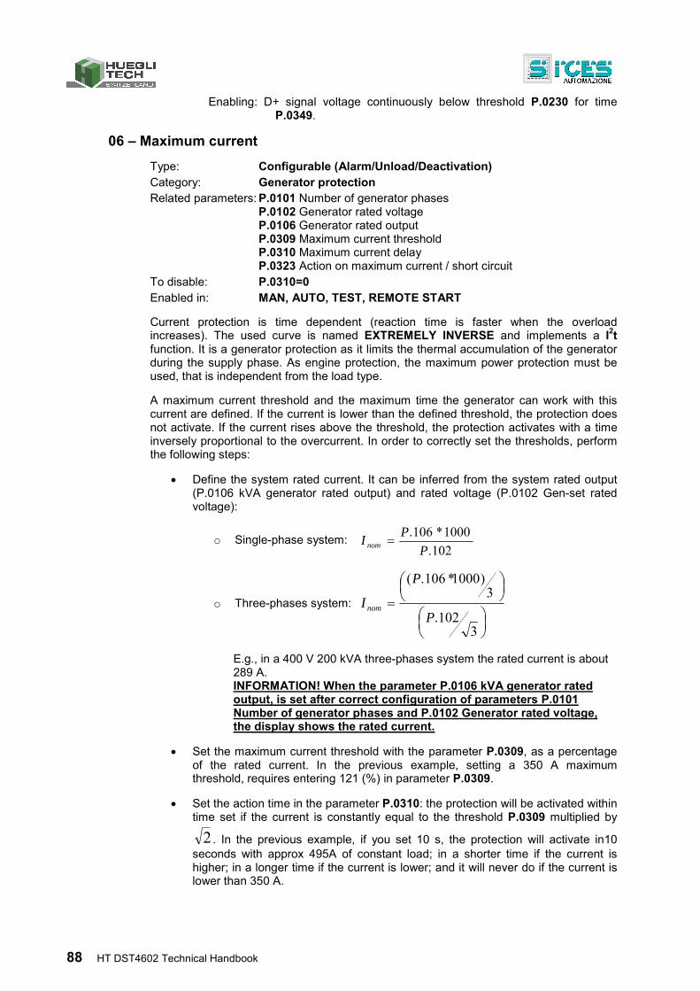
88 HT DST4602 Technical Handbook
Enabling: D+ signal voltage continuously below threshold P.0230 for time P.0349.
06 – Maximum current
Type: Configurable (Alarm/Unload/Deactivation) Category: Generator protection Related parameters: P.0101 Number of generator phases
P.0102 Generator rated voltage P.0106 Generator rated output P.0309 Maximum current threshold P.0310 Maximum current delay P.0323 Action on maximum current / short circuit
To disable: P.0310=0 Enabled in: MAN, AUTO, TEST, REMOTE START
Current protection is time dependent (reaction time is faster when the overload increases). The used curve is named EXTREMELY INVERSE and implements a I2t function. It is a generator protection as it limits the thermal accumulation of the generator during the supply phase. As engine protection, the maximum power protection must be used, that is independent from the load type.
A maximum current threshold and the maximum time the generator can work with this current are defined. If the current is lower than the defined threshold, the protection does not activate. If the current rises above the threshold, the protection activates with a time inversely proportional to the overcurrent. In order to correctly set the thresholds, perform the following steps:
Define the system rated current. It can be inferred from the system rated output (P.0106 kVA generator rated output) and rated voltage (P.0102 Gen-set rated voltage):
o Single-phase system: 102.
1000*106.
P
PI nom
o Three-phases system:
3102.
3)1000*106.(
P
P
Inom
E.g., in a 400 V 200 kVA three-phases system the rated current is about 289 A. INFORMATION! When the parameter P.0106 kVA generator rated output, is set after correct configuration of parameters P.0101 Number of generator phases and P.0102 Generator rated voltage, the display shows the rated current.
Set the maximum current threshold with the parameter P.0309, as a percentage of the rated current. In the previous example, setting a 350 A maximum threshold, requires entering 121 (%) in parameter P.0309.
Set the action time in the parameter P.0310: the protection will be activated within time set if the current is constantly equal to the threshold P.0309 multiplied by
2 . In the previous example, if you set 10 s, the protection will activate in10 seconds with approx 495A of constant load; in a shorter time if the current is higher; in a longer time if the current is lower; and it will never do if the current is lower than 350 A.
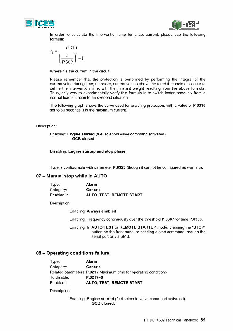
HT DST4602 Technical Handbook 89
In order to calculate the intervention time for a set current, please use the following formula:
1309.
310.2
P
I
PtI
Where I is the current in the circuit.
Please remember that the protection is performed by performing the integral of the current value during time; therefore, current values above the rated threshold all concur to define the intervention time, with their instant weight resulting from the above formula. Thus, only way to experimentally verify this formula is to switch instantaneously from a normal load situation to an overload situation.
The following graph shows the curve used for enabling protection, with a value of P.0310 set to 60 seconds (I is the maximum current):
Description:
Enabling: Engine started (fuel solenoid valve command activated). GCB closed.
Disabling: Engine startup and stop phase
Type is configurable with parameter P.0323 (though it cannot be configured as warning).
07 – Manual stop while in AUTO
Type: Alarm Category: Generic Enabled in: AUTO, TEST, REMOTE START
Description:
Enabling: Always enabled
Enabling: Frequency continuously over the threshold P.0307 for time P.0308.
Enabling: In AUTO/TEST or REMOTE STARTUP mode, pressing the “STOP” button on the front panel or sending a stop command through the serial port or via SMS.
08 – Operating conditions failure
Type: Alarm Category: Generic Related parameters: P.0217 Maximum time for operating conditions To disable: P.0217=0 Enabled in: AUTO, TEST, REMOTE START
Description:
Enabling: Engine started (fuel solenoid valve command activated). GCB closed.
90 HT DST4602 Technical Handbook
Generator voltage and frequency in tolerance.
Enabling: Generator voltages and frequency are not stable in the tolerance range within time P.0217 from the engine running acknowledgement (or from the end of the engine’s idle cycle, if enabled).
11 – Power reverse
Type: Alarm Category: Generator protection Related parameters: P.0106 Generator rated output
P.0313 Power reverse threshold P.0314 Power reverse delay
To disable: P.0314=0 Enabled in: MAN, AUTO, TEST, REMOTE START
Description:
Enabling: Engine started (fuel solenoid valve command activated). GCB closed.
Disabling: Engine startup and stop phase
Enabling: It activates if, in the previous conditions, the system total active power is negative and has an absolute value continuously greater than the threshold P.0313, for time P.0314. INFORMATION! The parameter P.0313 Power reverse threshold is expressed as a percentage of parameter P.0106 Generator rated output.
12 – Gen-set locked
Type: Alarm Category: Generic Enabled in: MAN, AUTO, TEST, REMOTE START
Description:
Enabling: Always enabled.
Enabling: When a “LOCK” command is received through the serial port or via SMS.
Deactivation: When an “UNLOCK” command is received through the serial port or via SMS.
INFORMATION! Disconnecting the controller from the battery cannot disable the protection.
The gen-set cannot be started either manually or automatically. This lock is used for: time rental, lack of maintenance, economic litigation, etc.
HT DST4602 Technical Handbook 91
For more details, please refer to [4] Serial communication.
13 – Mains circuit breaker (MCB) not closed
Type: Warning Category: Generic, load protection Related parameters: P.2001 Function of Input 1
P.2002 Delay for input 1 Ref. par. 5.1 Contact/analog Protection inputs To disable: P.2002=0 Enabled in: MAN, AUTO, TEST, REMOTE START
Description:
Enabling: Value Parameter P.2001=3002 MCB closed
Enabling: Input status remains continuously 'not active' (open input) for time set in P.2002.
When this warning is activated, you can also force the engine to start and the loads to switch to the gen-set by using the parameter P.0221- Engine enabling on MCB faults.
14 – Genset circuit breaker (GCB) not closed
Type: Deactivation/Warning Category: Generic Related parameters: P.2001 Function of Input 1
P.2002 Delay for input 1 Ref. par. 5.1 Contact/analog Protection inputs To disable: P.2002=0 Enabled in: MAN, AUTO, TEST, REMOTE START
Description:
Enabling: Parameter P.2001 value=3001 Engine started (fuel solenoid valve command activated). GCB closed.
Disabling: Engine startup and stop phase
Enabling: Input status remains continuously 'not active' (open input) for time set in P.2002.
Deactivation: in AUTO, TEST, or REMOTE START mode and only when GCB is closed and the digital input status remains continuously not active (open input) for the time set in P.2002, after three consecutive attempts.
Warning: in MAN mode and only when GCB is closed and the digital input status remains continuously not active (open input) for the time set in P.2002.
No automatic change-over to the mains is provided.
92 HT DST4602 Technical Handbook
15 – Overload (from contact)
Type: Alarm Category: Generator protection Related parameters: P.2001 Function of Input 1
P.2002 Delay for input 1 Ref. par. 5.1 Contact/analog Protection inputs To disable: P.2002=0 Enabled in: MAN, AUTO, TEST, REMOTE START
Description:
Enabling: Parameter P.2001 value=4241, P.2002 other than 0 Engine started (fuel solenoid valve command activated) GCB closed.
Disabling: Engine startup and stop phase
Enabling: Input status remains continuously active (closed input) for the time set in P.2002.
16 – Short circuit on the generator
Type: Configurable (Alarm/Unload/Deactivation) Category: Generator protection Related parameters: P.0101 Number of generator phases
P.0102 Generator rated voltage P.0106 Generator rated output P.0311 Short circuit threshold P.0312 Short circuit delay P.0323 Action on maximum current/short circuit
To disable: P.0312=0 Enabled in: MAN, AUTO, TEST, REMOTE START
Description:
Enabling: Engine started (fuel solenoid valve command activated). GCB closed. Generator voltage and frequency in tolerance.
Disabling: Engine startup and stop phase
Enabling: At least one phase continuously over threshold P.0311 for time P.0312.
Short circuit protection for quick operation independently of timing for the maximum current protection curve. Protection is given by setting a threshold P.0311 expressed as a percentage of the system rated current (see maximum current protection to calculate rated current with parameters P.0101, P.0102 and P.0106). Typology is configurable with parameter P.0323 (though it cannot be configured as a warning).
HT DST4602 Technical Handbook 93
17 – Overspeed (from contact)
Type: Alarm Category: Engine protection Related parameters: P.2001 Function of Input 1
P.2002 Delay for input 1 Ref. par. 5.1 Contact/analog Protection inputs To disable: P.2002=0 Enabled in: MAN, AUTO, TEST, REMOTE START
Description:
Enabling: Value of parameter P.2001=4251, P.2002 other than 0 Engine started (fuel solenoid valve command activated).
Disabling: Engine startup and stop phase
Enabling: It activates if the configured input remains continuously active for the time associated in P.2002.
18 – Overspeed (due to engine speed )
Type: Alarm Category: Engine protection Related parameters: P.0110 Number of teeth of the pick-up wheel
P.0111 Rpm/W ratio P.0127 Rpm/Hz ratio P.0133 Engine rating (Primary) P.0134 Engine rating (Secondary) P.0333 Maximum speed threshold (pick-up/W) (%) P.0334 Maximum speed delay (pick-up/W) P.0700 Engine type
To disable: P.0334=0 Enabled in: MAN, AUTO, TEST, REMOTE START
Description:
Enabling: Engine started (fuel solenoid valve command activated).
Acquires engine speed measure:
Pick_up: From its Pick-up input (terminals 7-8-9 of connector J27, P.0110 other than from zero).
W: From its W input (terminal 7 of connector J27, P.0111 other than zero).
ECU Interface: From CANBUS (P.0700 other than zero, ECU configured)
Generator frequency: From generator frequency measured by the controller. (P.0127 other than 0)
Disabling: Engine startup and stop phase
94 HT DST4602 Technical Handbook
Enabling: It activates if acquired speed remains continuously over the threshold (P.0333 referred to P.0133 or P.0134 for time P.0334)
19 – Overspeed (from generator frequency)
Type: Alarm Category: Engine protection Related parameters: P.0105 Rated frequency (Hz)
P.0331 Maximum speed threshold (frequency) (expressed in %) P.0332 Maximum speed delay (frequency)
To disable: P.0332=0 Enabled in: MAN, AUTO, TEST, REMOTE START
Description:
Enabling: Engine started (fuel solenoid valve command activated).
Disabling: Engine startup and stop phase
Enabling: Frequency continuously over the threshold P.0331 referred to P.0105 for time P.0332.
20 – High battery voltage threshold 2 (from measure)
Type: Warning Category: Battery protection Related parameters: P.0371 High battery voltage threshold 2 (%)
P.0372 High battery voltage delay 2 To disable: P.0372=0 Enabled in: MAN, AUTO, TEST, REMOTE START
Description:
Enabling: Engine started and/or engine stopped
Disabling: Engine startup and stop phase
Enabling: If battery voltage remains continuously over threshold P.0371 for time P.0372
INFORMATION! Thresholds are expressed as a percentage of the battery rated voltage, which is non settable but is automatically selected by the controller between 12 and 24 Vdc. Selection is made when the controller is powered and every time the key is switched to OFF/RESET. If the controller previously sensed a value lower than, or equal to, 17V, it considers to be powered by a 12 V battery, otherwise it will consider a 24V rated voltage.
21 – Engine not stopped (Stop failure)
Type: Alarm Category: Generic Related parameters: P.0214 Duration of stopping cycle(s) To disable: P.0214=0
HT DST4602 Technical Handbook 95
Enabled in: AUTO, TEST, REMOTE START
Description:
Enabling: Engine started (fuel solenoid valve command activated).
Disabling: Engine startup and stop phase
Enabling: Engine does not stop within time set in P.0214 (since the stop command).
INFORMATION! This alarm can be activated even if another one is already active.
22 – Overcrank
Type: Alarm Category: Battery protection Related parameters: P.0211 Number of startup attempts To disable: - Enabled in: AUTO, TEST, REMOTE START
Description:
Disabling: Cannot be disabled
Enabling: The controller performed P.0211 consecutive engine start attempts (auto start) without success (engine not running).
23 – Mains circuit breaker (MCB) not open
Type: Deactivation/Warning Category: Generic Related parameters: P.2001 Function of Input 1
P.2002 Delay for input 1 Ref. par. 5.1 Contact/analog Protection inputs To disable: P.2002=0 Enabled in: MAN, AUTO, TEST, REMOTE START
Description:
Enabling: Value of parameter P.2001=3002, P.2002 other than 0
It activates when MCB is open and the digital input status remains continuously active (closed) for the set time. In auto mode it activates after three consecutive attempts. It can be:
Deactivation: when the controller is in one of the auto modes and:
if stable command for MCB closing is used (function 2004 in one of the digital outputs).
for plants with only mains short time parallel:
If GCB is closed (i.e. in mains parallel, though this cannot be maintained; due to MCB not opening, deactivation is forced in order to open GCB).
96 HT DST4602 Technical Handbook
If GCB is open but cannot be closed with synchronization: as MCB does not open, CGB cannot be closed and therefore the engine stops.
Warning: for all other events.
24 – Genset circuit breaker (GCB) not open
Type: Alarm/Warning Category: Generic Related parameters: P.2001 Function of Input 1
P.2002 Delay for input 1 Ref. par. 5.1 Contact/analog Protection inputs To disable: P.2002=0 Enabled in: MAN, AUTO, TEST, REMOTE START
Description:
Enabling: Value of parameter P.2001=3001, P.2002 other than 0. GCB open (relay at rest)
It activates when GCB is open and the digital input status remains continuously active (closed) for the set time. In auto mode it activates after three consecutive attempts. It can be:
Alarm: when the controller is in AUTO mode with engine running and only if the stable command is used for GCB closing (function 2034 in one of the digital outputs).
Warning: for all other events.
It normally provides only a signaling; for parallel plants it can force the MCB opening (for plants with only short time parallel).
25 – Minimum fuel level (from contact)
Type: Alarm/Warning Category: Generic Related parameters: P.2001 Function of Input 1
P.2002 Delay for input 1 Ref. par. 5.1 Contact/analog Protection inputs To disable: P.2002=0 Enabled in: MAN, AUTO, TEST, REMOTE START
Description:
Enabling: Value of parameter P.2001=4211, P.2002 other than 0 Engine started (fuel solenoid valve command activated).
Disabling: Engine startup and stop phase
Enabling: It activates if the configured input remains continuously active for the time associated in P.2002.
HT DST4602 Technical Handbook 97
It activates if the configured input remains continuously active for the time associated in P.2002.
26 – Minimum fuel level (from analog sensor)
Type: Alarm/Warning Category: Generic Related parameters: P.4033 Function of the input 5(FL) Fuel level (VDO)/Fuel level
(generic) P.0347 Minimum fuel level threshold (%) P.0348 Minimum fuel level delay
Ref. par. 5.1 Contact/analog Protection inputs To disable: P.0348=0 Enabled in: MAN, AUTO, TEST, REMOTE START
Description:
Enabling: Value of parameter P.4033=1220/1221, P.0348 other than 0 Engine started (fuel solenoid valve command activated).
If the controller is set to use the fuel level analog sensor (value 1220 or 1221 and parameter P.4033 Function of the input 5(FL) duly configured), and if this sensor is physically connected to connector J27 at terminal 4.
Disabling: Engine startup and stop phase
Enabling: It activates if the measured value is below the percentage value in P.0347, and remains continuously active for the time associated in P.0348.
27 – Low fuel level (from contact)
Type: Warning Category: Generic Related parameters: P.2001 Function of Input 1
P.2002 Delay for input 1 Ref. par. 5.1 Contact/analog Protection inputs To disable: P.2002=0 Enabled in: MAN, AUTO, TEST, REMOTE START
Description:
Enabling: Value of parameter P.2001=4212, P.2002 other than 0 Engine started (fuel solenoid valve command activated).
Disabling: Engine startup and stop phase
Enabling: It activates if the configured input remains continuously active for the time associated in P.2002.
98 HT DST4602 Technical Handbook
28 – Low fuel level (from analog sensor)
Type: Warning Category: Generic Related parameters: P.4033 Function of the input 5(FL) Fuel level (VDO)/Fuel level
(generic) P.0345 Minimum fuel level threshold (%) P.0346 Low fuel level delay
To disable: P.0346=0 Enabled in: MAN, AUTO, TEST, REMOTE START
Description:
Enabling: Value of parameter P.4033=1220/1221, P.0346 other than 0 Engine started (fuel solenoid valve command activated).
If the controller is set to use the fuel level analog sensor (value 1220 or 1221 and parameter P.4033 Function of the input 5(FL) duly configured), and if this sensor is physically connected to connector J27 at terminal 4.
Disabling: Engine startup and stop phase
Enabling: It activates if the measured value is below the percentage value in P.0345, and remains continuously active for the time associated in P.0346.
29 – High fuel level (from contact)
Type: Warning Category: Generic Related parameters: P.2001 Function of Input 1
P.2002 Delay for input 1 Ref. par. 5.1 Contact/analog Protection inputs To disable: P.2002=0 Enabled in: MAN, AUTO, TEST, REMOTE START
Description:
Enabling: Value of parameter P.2001=4213, P.2002 other than 0 Engine started (fuel solenoid valve command activated).
Disabling: Engine startup and stop phase
Enabling: It activates if the configured input remains continuously active for the time associated in P.2002.
30 – High fuel level (from analog sensor)
Type: Warning Category: Generic Related parameters: P.4033 Function of the input 5(FL) Fuel level (VDO)/Fuel level
(generic)
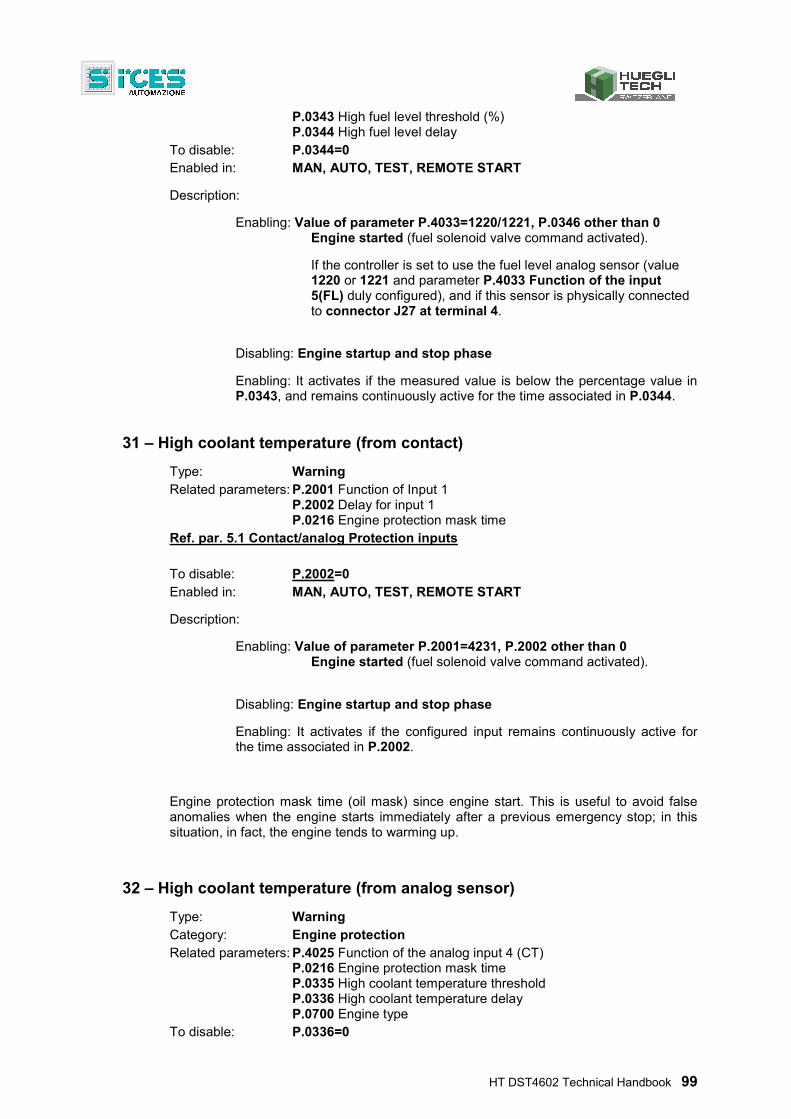
HT DST4602 Technical Handbook 99
P.0343 High fuel level threshold (%) P.0344 High fuel level delay
To disable: P.0344=0 Enabled in: MAN, AUTO, TEST, REMOTE START
Description:
Enabling: Value of parameter P.4033=1220/1221, P.0346 other than 0 Engine started (fuel solenoid valve command activated).
If the controller is set to use the fuel level analog sensor (value 1220 or 1221 and parameter P.4033 Function of the input 5(FL) duly configured), and if this sensor is physically connected to connector J27 at terminal 4.
Disabling: Engine startup and stop phase
Enabling: It activates if the measured value is below the percentage value in P.0343, and remains continuously active for the time associated in P.0344.
31 – High coolant temperature (from contact)
Type: Warning Related parameters: P.2001 Function of Input 1
P.2002 Delay for input 1 P.0216 Engine protection mask time
Ref. par. 5.1 Contact/analog Protection inputs To disable: P.2002=0 Enabled in: MAN, AUTO, TEST, REMOTE START
Description:
Enabling: Value of parameter P.2001=4231, P.2002 other than 0 Engine started (fuel solenoid valve command activated).
Disabling: Engine startup and stop phase
Enabling: It activates if the configured input remains continuously active for the time associated in P.2002.
Engine protection mask time (oil mask) since engine start. This is useful to avoid false anomalies when the engine starts immediately after a previous emergency stop; in this situation, in fact, the engine tends to warming up.
32 – High coolant temperature (from analog sensor)
Type: Warning Category: Engine protection Related parameters: P.4025 Function of the analog input 4 (CT)
P.0216 Engine protection mask time P.0335 High coolant temperature threshold P.0336 High coolant temperature delay P.0700 Engine type
To disable: P.0336=0
100 HT DST4602 Technical Handbook
Ref. par. 5.1 Contact/analog Protection inputs Enabled in: MAN, AUTO, TEST, REMOTE START
Description:
Enabling: Value of parameter P.4025=1110/1111, P.0346 other than 0, P.0700 other than 0 (ECU configured). Engine started (fuel solenoid valve command activated).
If the controller is set to use the cooling temperature analog sensor AN.INPUT 4 (Value 1110 or 1111 and parameter P.4025 Function of the input 4(CT) duly configured), and if this sensor is physically connected to connector J27 at terminal 3.
Disabling: Engine startup and stop phase
Enabling: If the measure is continuously higher than or equal to the threshold P.0335 for time P.0336 time, but only after elapsed time P.0216 (oil mask) since engine start.
This protection is enabled only if the controller acquires the measure of the engine coolant temperature.
33 – Maximum coolant temperature (from contact)
Type: Alarm/Warning Category: Engine protection Related parameters: P.2001 Function of Input 1
P.2002 Delay for input 1 P.0216 Engine protection mask time
Ref. par. 5.1 Contact/analog Protection inputs To disable: P.2002=0 Enabled in: MAN, AUTO, TEST, REMOTE START
Description:
Enabling: Value of parameter P.2001=4232, P.2002 other than 0 Engine started (fuel solenoid valve command activated).
Disabling: Engine startup and stop phase
Enabling: It activates if the configured input remains continuously active for the time associated in P.2002.
Engine protection mask time (oil mask) since engine start. This is useful to avoid false anomalies when the engine starts immediately after a previous emergency stop; in this situation, in fact, the engine tends to warming up.
34 – Maximum coolant temperature (from analog sensor)
Type: Alarm/Warning Category: Engine protection
HT DST4602 Technical Handbook 101
Related parameters: P.4025 Function of the analog input 4 (CT) P.0216 Engine protection mask time P.0337 Maximum coolant temperature threshold P.0338 Maximum coolant temperature delay P.0700 Engine type
Ref. par. 5.1 Contact/analog Protection inputs To disable: P.0338=0 Enabled in: MAN, AUTO, TEST, REMOTE START
Description:
Enabling: Value of parameter P.4025=1110/1111, P.0338 other than 0, P.0700 other than 0 (ECU configured). Engine started (fuel solenoid valve command activated).
If the controller is set to use the cooling temperature analog sensor AN.INPUT 4 (Value 1110 or 1111 and parameter P.4025 Function of the input 4(CT) duly configured), and if this sensor is physically connected to connector J27 at terminal 3.
Disabling: Engine startup and stop phase
Enabling: If the measure is continuously higher than or equal to the threshold P.0337 for time P.0338, but only after elapsed time P.0216 (oil mask) since engine start.
This protection is enabled only if the controller acquires the measure of the engine coolant temperature.
35 – Maximum oil temperature (from measure)
Type: Alarm/Warning Category: Engine protection Related parameters: P.4001 Function of the analog input 1
P.0216 Engine protection mask time P.0375 Maximum oil temperature threshold P.0376 Maximum oil temperature delay P.0700 Engine type
Ref. par. 5.1 Contact/analog Protection inputs To disable: P.0376=0 Enabled in: MAN, AUTO, TEST, REMOTE START
Description:
Enabling: Value of parameter P.4001=1101, P.0346 other than 0, P.0700 other than 0 (ECU configured). Engine started (fuel solenoid valve command activated).
If the controller is set to use the engine oil temperature analog sensor AN.INPUT 1 (Value 1101 and parameter P.4001 Function of the input 1 duly configured), and if this sensor is
102 HT DST4602 Technical Handbook
physically connected to connector J15 at terminal 1.
Disabling: Engine startup and stop phase
Enabling: If the measure is continuously higher than or equal to the threshold P.0375 for time P.0376, but only after elapsed time P.0216 (oil mask) since engine start.
36 – Low battery voltage threshold 2 (from measure)
Type: Warning Category: Battery protection Related parameters: P.0369 Low battery voltage threshold 2 (%)
P.370 Low battery voltage delay 2 To disable: P.0370=0 Enabled in: MAN, AUTO, TEST, REMOTE START
It is always enabled except when the cranking motor is activated. It activates if the battery voltage is continuously lower than the threshold P.0369 for time P.0370.
INFORMATION! The threshold P.0369 is expressed as a percentage of the rated battery voltage which is not configurable but is automatically selected by the controller between 12 e 24 Vdc..
The selection is made every time the controller is powered and every time the key is switched to OFF/RESET. If the controller previously sensed a value lower than, or equal to, 17V, it considers to be powered by a 12 V battery, otherwise it will consider a 24V rated voltage.
37 – Low battery voltage threshold 1 (from measure)
Type: Warning Category: Battery protection Related parameters: P.0362 Low battery voltage threshold 1 (%)
P.0363 Low battery voltage delay 1 To disable: P.0363=0 Enabled in: MAN, AUTO, TEST, REMOTE START
It is always enabled except when the cranking motor is activated. It activates if the battery voltage is continuously lower than the threshold P.0362 for time P.0370.
INFORMATION! The threshold P.0369 is expressed as a percentage of the battery rated voltage, which is non settable but is automatically selected by the controller between 12 and 24 Vdc. Selection is made when the controller is powered and every time the key is switched to OFF/RESET. If the controller previously sensed a value lower than, or equal to, 17V, it considers to be powered by a 12 V battery, otherwise it will consider a 24V rated voltage.
38 – High battery voltage threshold 1 (from measure)
Type: Warning Category: Battery protection Related parameters: P.0364 High battery voltage threshold 1 (%)
P.0365 High battery voltage delay 1
HT DST4602 Technical Handbook 103
To disable: P.0365=0 Enabled in: MAN, AUTO, TEST, REMOTE START
It is always enabled except when the cranking motor is activated. It activates if the battery voltage continuously exceeds the threshold P.0364 for time P.0365.
INFORMATION! The threshold P.0364 is expressed as a percentage of the rated battery voltage which is not settable but is automatically selected by the controller between 12 e 24 Vdc..
The selection is made every time the controller is powered and every time the key is switched to OFF/RESET. If the controller previously sensed a value lower than, or equal to, 17V, it considers to be powered by a 12 V battery, otherwise it will consider a 24V rated voltage.
39 – Service required
Type: Configurable Category: Generic Related parameters: P.0424 Maintenance interval (running hours)
P.0425 Kind of maintenance action
To disable: P.0424=0 Enabled in: MAN, AUTO, TEST, REMOTE START
Description:
Enabling: It activates after P.0424 engine running hours since last parameter P.0424 setting.
Deactivation: Only possible setting P.0424 again, setting it to zero to disable the function or confirming the actual value or setting a new one.
INFORMATION! Engine operating hours are counted even when engine is not started by the controller. When activated, it acts as warning, deactivation or alarm as configured with P.0425. It cannot be cancelled even disconnecting the controller's power supply.
To be programmed, parameters P.0424 and P.0425 require “installer” access level: this function can be used for gen-set rental in order to lock the gen-set when the established hours are elapsed.
41 – Minimum oil pressure (from contact)
Type: Alarm Category: Engine protection Related parameters: P.2001 Function of Input 1
P.2002 Delay for input 1 P.0216 Engine protection mask time
Ref. par. 5.1 Contact/analog Protection inputs To disable: P.2002=0
104 HT DST4602 Technical Handbook
Enabled in: MAN, AUTO, TEST, REMOTE START
Description:
Enabling: Value of parameter P.2001=4221, P.2002 other than 0 Engine started (fuel solenoid valve command activated).
Disabling: Engine startup and stop phase
Enabling: It activates if the configured input remains continuously active for the time associated in P.2002, but only after elapsed time P.0216 (oil mask) since engine start.
42 – Minimum oil pressure (from measure)
Type: Alarm Category: Engine protection Related parameters: P.4017 Function of the analog input 1
P.0216 Engine protection mask time P.0341 Minimum oil pressure threshold P.0342 Minimum oil pressure delay P.0700 Engine type
Ref. par. 5.1 Contact/analog Protection inputs To disable: P.0342=0 Enabled in: MAN, AUTO, TEST, REMOTE START
Description:
Enabling: Value parameter P.4017=1000/1001, P.0342 other than 0, P.0700 other than 0 (ECU configured). Engine started (fuel solenoid valve command activated).
If the controller is set to use the engine oil pressure analog sensor AN.INPUT 3 (Value 1000 or 1001 and parameter P.4017 Function of the input 3 duly configured), and if this sensor is physically connected to connector J27 at terminal 2.
Disabling: Engine startup and stop phase
Enabling: If the measure is continuously lower than or equal to the threshold P.0341 for time P.0342 time, but only after elapsed time P.0216 (oil mask) since engine start.
43 – Low oil pressure (from contact)
Type: Warning Category: Engine protection Related parameters: P.2001 Function of Input 1
P.2002 Delay for input 1 P.0216 Engine protection mask time
Ref. par. 5.1 Contact/analog Protection inputs To disable: P.2002=0
HT DST4602 Technical Handbook 105
Enabled in: MAN, AUTO, TEST, REMOTE START
Description:
Enabling: Value of parameter P.2001=4222, P.2002 other than 0 Engine started (fuel solenoid valve command activated).
Disabling: Engine startup and stop phase
Enabling: It activates if the configured input remains continuously active for the time associated in P.2002, but only after elapsed time P.0216 (oil mask) since engine start.
44 – Low oil pressure (from measure)
Type: Warning Category: Engine protection Related parameters: P.0112 P.0216 P.0339 P.0340 P.0700 To disable: P.0340=0 Enabled in: MAN, AUTO, TEST, REMOTE START Related parameters: P.4017 Function of the analog input 1
P.0216 Engine protection mask time P.0339 Low oil pressure threshold P.0340 Low oil pressure delay P.0700 Engine type
Ref. par. 5.1 Contact/analog Protection inputs To disable: P.0340=0 Enabled in: MAN, AUTO, TEST, REMOTE START
Description:
Enabling: Value parameter P.4017=1000/1001, P.0340 other than 0, P.0700 other than 0 (ECU configured). Engine started (fuel solenoid valve command activated).
If the controller is set to use the engine oil pressure analog sensor AN.INPUT 3 (Value 1000 or 1001 and parameter P.4017 Function of the input 3 duly configured), and if this sensor is physically connected to connector J27 at terminal 2.
Disabling: Engine startup and stop phase
Enabling: If the measure is continuously lower than or equal to the threshold P.0339 for time P.0340, but only after elapsed time P.0216 (oil mask) since engine start.
45 – Maximum auxiliary current
Type: Alarm Category: Generic Related parameters: P.0108 Primary of AT or toroid ratio for auxiliary current
P.0140 Secondary of AT or toroid ratio for auxiliary current P.0131 Usage of auxiliary current.
106 HT DST4602 Technical Handbook
P.0109 Transformer type for auxiliary current P.0367 Auxiliary current/differential threshold. P.0368 Auxiliary current/differential delay
To disable: P.0368=0 Enabled in: MAN, AUTO, TEST, REMOTE START
Enabling: Value of parameter P.0108 other than 0, P.0109 other than 0.
Enabling: If auxiliary current measure remains continuously over the threshold P.0367 for time P.0368 but only after elapsed time P.0216.
48 – Emergency stop
Type: Alarm Category: Generic Related parameters: P.2001 Function of Input 1
P.2002 Delay for input 1
Ref. par. 5.1 Contact/analog Protection inputs To disable: P.2002=0 Enabled in: MAN, AUTO, TEST, REMOTE START
Description:
Enabling: Value of parameter P.2001=4201, P.2002 other than 0
Enabling: It activates if the configured input remains continuously active for the time associated in P.2002, but only after elapsed time P.0216 (oil mask) since engine start.
INFORMATION! “EMERGENCY STOP” acquisition has negative logic as opposed to
the other input functions. Input to GND anomaly not active.
49 – Maximum power
Type: Configurable (Warning/Alarm/Unload/Deactivation) Category: Engine protection Related parameters: P.0350 Maximum power threshold
P.0351 Maximum power delay P.0352 Maximum power action
To disable: P.0351=0 Enabled in: MAN, AUTO, TEST, REMOTE START
It activates if the system total active power is positive and remains continuously over the threshold P.0350 for time P.0351. With parameter P.0352 it is possible to select the protection to be activated (warning, deactivation, deactivation with power unload, alarm).
Enabling: Engine started (fuel solenoid valve command activated).
Disabling: Engine startup and stop phase
HT DST4602 Technical Handbook 107
Enabling: If power is negative and remains continuously over the threshold P.0350 for time P.0351.
51 – High controller temperature
Type: Warning Category: Controller protection Related parameters: P.0366 Controller high temperature threshold To disable: P.0366=99 (maximum value) Enabled in: MAN, AUTO, TEST, REMOTE START
Enabling: It activates if the internal controller temperature is over the threshold P.0366, even for an instant.
52 – Generator voltages unbalance
Type: Alarm Category: Generator protection Related parameters: P.0101 Number of generator phases
P.0102 Generator rated voltage P.0315 Voltages unbalance threshold (% rated phase voltage) P.0316 Voltages unbalance delay
To disable: P.0316=0 Enabled in: MAN, AUTO, TEST, REMOTE START
Description: It represents the maximum acceptable difference (absolute value) between
any of two phase-to-phase voltages.
Enabling: Parameter P.0103 = 3 (three-phase system) Engine started (fuel solenoid valve command activated) Voltages and frequency within the tolerance range
Disabling: Engine startup and stop phase
Enabling: It activates if the difference between two phase-to-phase voltages (absolute value) is continuously over the threshold P.0315 for time P.0316.
53 – Generator current unbalance
Type: Alarm Category: Generator protection Related parameters: P.0101 Number of generator phases
P.0102 Generator rated voltage P.0106 Generator rated output P.0317 Current unbalance threshold (% rated current) P.0318 Current unbalance delay
To disable: P.0318=0 Enabled in: MAN, AUTO, TEST, REMOTE START
108 HT DST4602 Technical Handbook
Description: It represents the maximum acceptable difference (absolute value) between
any of two phase currents.
Enabling: Parameter P.0103 = 3 (three-phase system) Engine started (fuel solenoid valve command activated) Voltages and frequency within the tolerance range AT set on load with GCB closed AT set on generator with GCB closed or open
Disabling: Engine startup and stop phase
Enabling: It activates if the difference between any of two currents (absolute value) is continuously over the threshold P.0317 for time P.0318.
Refer to protection “06 - maximum current” to obtain the rated current from P.0102 and P.0106.
54 – High oil temperature (from measure)
Type: Warning Category: Engine protection Related parameters: P.4001 Function of the analog input 1
P.0216 Engine protection mask time P.0373 High oil temperature threshold P.0374 High oil temperature delay P.0700 Engine type
Ref. par. 5.1 Contact/analog Protection inputs To disable: P.0374=0 Enabled in: MAN, AUTO, TEST, REMOTE START
Description:
Enabling: Value of parameter P.4001=1101, P.0346 other than 0, P.0700 other than 0 (ECU configured). Engine started (fuel solenoid valve command activated).
If the controller is set to use the engine oil temperature analog sensor AN.INPUT 1 (Value 1101 and parameter P.4001 Function of the input 1 duly configured), and if this sensor is physically connected to connector J15 at terminal 1.
Disabling: Engine startup and stop phase
Enabling: If the measure is continuously higher than or equal to the threshold P.0372 for time P.0373, but only after elapsed time P.0216 (oil mask) since engine start.
55 – Wrong phases sequence
Type: Configurable (Warning/Alarm/Unload/Deactivation) Category: Generator protection
HT DST4602 Technical Handbook 109
Related parameters: P.0101 Number of generator phases P.0319 Generator phases sequence (required) P.0320 Wrong generator phases sequence action
To disable: P.0319=0 Enabled in: MAN, AUTO, TEST, REMOTE START
Description: It represents the maximum acceptable difference (absolute value) between
any of two phase currents.
Enabling: Parameter P.0103 = 3 (three-phase system) Engine started (fuel solenoid valve command activated) Voltages and frequency within the tolerance range Load switched to mains (switchover to generator
Disabling: Engine startup and stop phase
Enabling: It activates if the generator phases rotation direction does not match with the one set in parameter P.0319 (0 = function disable, 1 = clockwise direction, 2 = counter-clockwise direction), with a 0.5 sec. filter time.
56 – Low generator voltage
Type: Warning Category: Load protection Related parameters: P.0101 Number of phases of the generator
P.0102 Generator rated voltage P.0202 Generator measures hysteresis P.0391 Low voltage threshold P.0392 Low voltage delay
To disable: P.0392=0 Enabled in: MAN, AUTO, TEST, REMOTE START
Description:
Enabling: Engine started (fuel solenoid valve command activated). GCB closed. Generator voltage and frequency in tolerance.
Disabling: Engine startup and stop phase
Enabling: At least one of the generator voltages continuously lower than the threshold P.0391 for time P.0392.
110 HT DST4602 Technical Handbook
57 – Clock not valid
Type: Warning Category: Generic Related parameters: P.0418 Weekly test schedule
P.0420 Test duration P.0421 Weekly operation schedule P.0422 Operation start time P.0423 Operation end time
Enabled in: MAN, AUTO, TEST, REMOTE START
Enabling: Always enabled
Enabling: If the controller detects a not-valid clock status, and functions using the clock are set, such as the weekly test (P.0418 and P.0420) or the operation enable time (P.0421, P.0422, P.0423).
Deactivation: Set the clock.
58 – Low generator frequency
Type: Warning Category: Load protection Related parameters: P.0105 Rated frequency
P.0395 Low frequency threshold P.0396 Low frequency delay
To disable: P.0396=0 Enabled in: MAN, AUTO, TEST, REMOTE START
Description:
Enabling: Engine started (fuel solenoid valve command activated). GCB closed. Generator voltage and frequency in tolerance.
Disabling: Engine startup and stop phase
Enabling: Frequency is continuously lower than the threshold P.0395 for time P.0396.
59 – High generator voltage
Type: Warning Category: Load/generator protection Related parameters: P.0101 Number of generator phases
P.0102 Generator rated voltage P.0202 Generator measures hysteresis P.0393 High voltage threshold P.0394 High voltage delay
To disable: P.0394=0 Enabled in: MAN, AUTO, TEST, REMOTE START
Description:
Enabling: Engine started (fuel solenoid valve command activated). GCB closed.
HT DST4602 Technical Handbook 111
Generator voltage and frequency in tolerance.
Disabling: Engine startup and stop phase
Enabling: At least one of the generator voltages continuously lower than the threshold P.0393 for time P.0394.
60 – High generator frequency
Type: Warning Category: Load/generator protection Related parameters: P.0105 Nominal frequency
P.0397 High frequency threshold P.0398 High frequency delay
To disable: P.0398=0 Enabled in: MAN, AUTO, TEST, REMOTE START
Description:
Enabling: Engine started (fuel solenoid valve command activated). GCB closed. Generator voltage and frequency in tolerance.
Disabling: Engine startup and stop phase
Enabling: Frequency continuously higher than the threshold P.0397 for time P.0398.
61 – Lost Excitation
Type: Alarm Category: Generator protection Related parameters: P.0321 Excitation loss threshold
P.0322 Excitation loss delay To disable: P.0322 = 0 Enabled in: MAN, AUTO, TEST, REMOTE START To disable: P.0398=0 Enabled in: MAN, AUTO, TEST, REMOTE START
Description:
Enabling: Engine started (fuel solenoid valve command activated). Generator frequency over 40Hz
Disabling: Engine startup and stop phase
Enabling: If reactive power is negative and remains continuously over the threshold P.0321 for time P.0322.
62 – Faulty engine CAN BUS 0 link
Type: Configurable (Warning/Alarm/Unload/Deactivation) Category: Generic
112 HT DST4602 Technical Handbook
Related parameters: P.0700 Engine type P.0703 ECU Can-Bus command level P.0709 Warning for ECU Can-Bus fault
Enabled in: MAN, AUTO, TEST, REMOTE START
Enabling: P.0700 other than 0 (ECU configured)
Enabling: It activates if the internal CAN controller switches to BUS-OFF status due to bus communication errors.
64 – Fuel pump failure
Type: Warning Category: Fuel pump protection Related parameters: P.0404 Fuel pump start maximum duration
P.3001 (for output 45 or equivalent for other outputs) To disable: P.3002 = 0 Enabled in: MAN, AUTO, TEST, REMOTE START
Description:
Enabling: Engine started (fuel solenoid valve command activated).
Disabling: Engine startup and stop phase
Enabling: If a configured output is present to control the fuel pump (code 1032 in P.3001 or equivalent for other outputs). It activates if the pump keeps running for the time P.3002 other than zero.
Configurable parameters for digital outputs are P.3001 to P.3016 for the HT DST4602 device and P.3021 to P.3566 for the DITEL devices.
In the following example, the digital output OUTPUT 1 of the controller HT DST4602 has been configured.
65 – Low coolant temperature (from analog sensor)
Type: Warning Category: Generic Related parameters: P.4025 Function of the analog input 4 (CT)
P.0216 Engine protection mask time P.0353 Low coolant temperature threshold P.0354 Low coolant temperature delay P.0700 Low coolant temperature delay
To disable: P.0354 = 0 Ref. par. 5.1 Contact/analog Protection inputs Enabled in: MAN, AUTO, TEST, REMOTE START
HT DST4602 Technical Handbook 113
Description:
Enabling: Value parameter P.4025=1110/1111, P.0354 other than 0, P.0700 other than 0.
If the controller is set to use the cooling temperature analog sensor AN.INPUT 4 (Value 1110 or 1111 and parameter P.4025 Function of the input 4(CT) duly configured), and if this sensor is physically connected to connector J27 at terminal 3.
Disabling:
Enabling: If the measure, even with engine stopped, is continuously lower than the threshold P.0353 for the time P.0354.
This protection is enabled only if the controller acquires the measure of the engine coolant temperature.
98 – Maximum time without CANBUS 0 data (engine)
Type: Configurable (Warning/Alarm/Unload/Deactivation) Category: Generic Related parameters: P.0700 Engine type
P.0709 CANBUS fault signal P.0711 Maximum time without messages from engine
To disable: P.0709 = 0 (not for MTU engines) Enabled in: MAN, AUTO, TEST, REMOTE START
Description:
Enabling: P.0700 other than 0 (ECU configured)
Enabling: If the controller does not receive continuous communication from the engine for the time P.0711. For value P.0700 MTU 140 to 147 it is enabled as per specification, when the controller does not continuously receive the message NMT ALIVE PDU for the set time.
99 – Minimum speed for asynchronous generators (from measure)
Type: Deactivation Category: Engine protection Related parameters: P.0110 Number of teeth of the pick-up wheel
P.0111 Rpm/W ratio P.0127 Rpm/Hz ratio P.0133 Engine rating (Primary) P.0134 Engine rating (Secondary) P.0305 Minimum speed threshold (pick-up/W) (%) P.0306 Minimum speed delay (pick-up/W) P.0700 Engine type
To disable: P.0306=0 Enabled in: MAN, AUTO, TEST, REMOTE START
114 HT DST4602 Technical Handbook
Description:
Enabling: Engine started (fuel solenoid valve command activated).
Acquires engine speed measure:
Pick_up: From its Pick-up input (terminals 7-8-9 of connector J27, P.0110 other than from zero).
W: From its W input (Terminal 7 of connector J27, P.0111 other than zero).
ECU Interface: From CANBUS (P.0700 other than zero).
Disabling: Engine startup and stop phase
Enabling: It activates if the acquired speed is continuously lower than the threshold (P.0305 referred to P.0133 or P.0134 for the time P.0306)
105 – Engine battery-charger failure (belt break from CANBUS 0)
Type: Warning Category: Engine protection Related parameters: P.0700 Engine type
P.0704 Can-Bus anomalies disable mask To disable: bit 12 of P.0704 on Enabled in: MAN, AUTO, TEST, REMOTE START
Enabling: P.0700 other than 0 (ECU configured)
Enabling: If the engine ECU CanBus signals the belt break status.
118 – Overspeed from CANBUS 0
Type: Alarm Category: Engine protection Related parameters: P.0700 Engine type
P.0704 Can-Bus anomalies disable mask To disable: bit 11 of P.0704 on Enabled in: MAN, AUTO, TEST, REMOTE START
Enabling: P.0700 other than 0 (ECU configured)
Enabling: If the engine sends an overspeed status signal over the CAN-BUS.
132 – High coolant temperature from CAN BUS 0
Type: Warning Category: Engine protection
HT DST4602 Technical Handbook 115
Related parameters: P.0700 Engine type P.0704 Can-Bus anomalies disable mask
To disable: bit 4 of P.0704 on Enabled in: MAN, AUTO, TEST, REMOTE START
Enabling: P.0700 other than 0 (ECU configured) Engine started (fuel solenoid valve command activated).
Disabling: Engine startup and stop phase
Enabling: If the engine sends a high temperature status signal over the CAN-BUS.
134 – Max. coolant temperature from CAN BUS 0
Type: Warning/Alarm Category: Engine protection Related parameters: P.0700 Engine type
P.0704 Can-Bus anomalies disable mask To disable: bit 5 of P.704 on Enabled in: MAN, AUTO, TEST, REMOTE START
It activates when the engine signals a maximum coolant temperature status over the CAN-BUS, but only after elapsed time P.0216 (oil mask) since engine start.
Enabling: P.0700 other than 0 (ECU configured) Engine started (fuel solenoid valve command activated).
Disabling: Engine startup and stop phase
Enabling: If the engine sends a maximum temperature status signal over the CAN-BUS.
135 – Minimum coolant level from CAN BUS 0
Type: Warning/Alarm Category: Engine protection Related parameters: P.0700 Engine type
P.0704 Can-Bus anomalies disable mask
To disable: bit 7 of P.0704 on Enabled in: MAN, AUTO, TEST, REMOTE START
Enabling: P.0700 other than 0 (ECU configured) Engine started (fuel solenoid valve command activated).
Disabling: Engine startup and stop phase
116 HT DST4602 Technical Handbook
Enabling: If the engine sends a minimum coolant level status signal over the CAN-BUS.
136 – Low coolant level from CAN BUS 0
Type: Warning Category: Engine protection Related parameters: P.0700 Engine type
P.0704 Can-Bus anomalies disable mask To disable: bit 6 of P.0704 on Enabled in: MAN, AUTO, TEST, REMOTE START
Enabling: P.0700 other than 0 (ECU configured) Engine started (fuel solenoid valve command activated).
Disabling: Engine startup and stop phase
Enabling: If the engine sends a low coolant level status signal over the CAN-BUS.
137 – Low battery voltage from CAN BUS 0
Type: Warning Category: Engine protection Related parameters: P.0700 Engine type
P.0704 Can-Bus anomalies disable mask To disable: bit 9 of P.0704 on Enabled in: MAN, AUTO, TEST, REMOTE START
Enabling: P.0700 other than 0 (ECU configured)
Enabling: If the engine sends a low battery voltage status signal over the CAN-BUS.
142 – Minimum oil pressure from CAN BUS 0
Type: Warning/Alarm Category: Engine protection Related parameters: P.0700 Engine type
P.0704 Can-Bus anomalies disable mask To disable: bit 1 of P.704 on Enabled in: MAN, AUTO, TEST, REMOTE START
Enabling: P.0700 other than 0 (ECU configured) Engine started (fuel solenoid valve command activated).
HT DST4602 Technical Handbook 117
Disabling: Engine startup and stop phase
Enabling: If the engine sends a minimum oil pressure status signal over the CAN-BUS.
144 – Low oil pressure from CAN BUS 0
Type: Warning Category: Engine protection Related parameters: P.0700 Engine type
P.0704 Can-Bus anomalies disable mask To disable: bit 0 of P.0704 on Enabled in: MAN, AUTO, TEST, REMOTE START
Enabling: P.0700 other than 0 (ECU configured) Engine started (fuel solenoid valve command activated).
Disabling: Engine startup and stop phase
Enabling: If the engine sends a low oil pressure status signal over the CAN-BUS.
158 – High oil temperature from CAN BUS
Type: Warning Category: Engine protection Related parameters: P.0700 Engine type
P.0704 Can-Bus anomalies disable mask To disable: bit 2 of P.0704 on Enabled in: MAN, AUTO, TEST, REMOTE START
Enabling: P.0700 other than 0 (ECU configured) Engine started (fuel solenoid valve command activated).
Disabling: Engine startup and stop phase
Enabling: If the engine sends a high oil temperature status signal over the CAN-BUS.
159 – Maximum oil temperature from CAN BUS
Type: Warning/Alarm Category: Engine protection Related parameters: P.0700 Engine type
P.0704 Can-Bus anomalies disable mask To disable: bit 3 of P.0704 on Enabled in: MAN, AUTO, TEST, REMOTE START
Enabling: P.0700 other than 0 (ECU configured) Engine started (fuel solenoid valve command activated).
Disabling: Engine startup and stop phase
Enabling: If the engine sends a maximum oil temperature status signal over the CAN-BUS.
118 HT DST4602 Technical Handbook
160 – Water in fuel from CAN BUS
Type: Warning Category: Engine protection Related parameters: P.0700 Engine type
P.0704 Can-Bus anomalies disable mask To disable: bit 8 of P.0704 on Enabled in: MAN, AUTO, TEST, REMOTE START
Enabling: P.0700 other than 0 (ECU configured)
Enabling: If the engine sends a water in fuel status signal over the CAN-BUS.
198 –Warnings from CAN BUS (cumulative)
Type: Warning Category: Engine protection Related parameters: P.0700 Engine type
P.0704 Can-Bus anomalies disable mask To disable: bit 14 of P.0704 on Enabled in: MAN, AUTO, TEST, REMOTE START
Enabling: P.0700 other than 0 (ECU configured)
Enabling: If the engine sends a warnings (cumulative) status signal over the CAN-BUS.
199 – Alarms from CAN BUS (cumulative)
Type: Warning/Alarm Category: Engine protection Related parameters: P.0700 Engine type
P.0704 Can-Bus anomalies disable mask To disable: bit 15 of P.0704 on Enabled in: MAN, AUTO, TEST, REMOTE START
Enabling: P.0700 other than 0 (ECU configured)
Enabling: If the engine sends an alarms (cumulative) status signal over the CAN-BUS. Only one warning is activated by the controller to signal the cumulative; the alarm should be set for one of the 1xx codes.
200 – Faulty CANBUS 1 (PMCB) BUS-OFF connection
Type: Warning Category: Generic Related parameters: P.0800 PMCB bus mode Enabled in: MAN, AUTO, TEST, REMOTE START
Enabling: P.0800 other than 0 (PMCB bus configured)
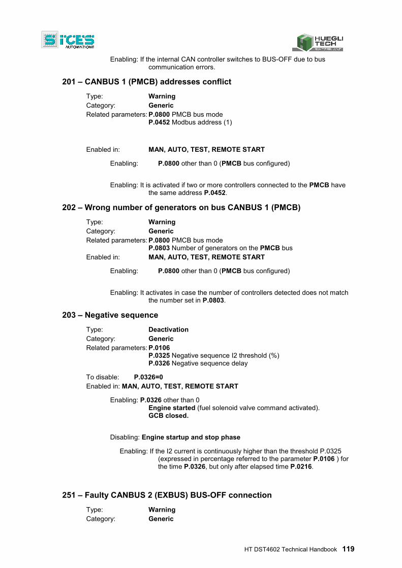
HT DST4602 Technical Handbook 119
Enabling: If the internal CAN controller switches to BUS-OFF due to bus communication errors.
201 – CANBUS 1 (PMCB) addresses conflict
Type: Warning Category: Generic Related parameters: P.0800 PMCB bus mode
P.0452 Modbus address (1) Enabled in: MAN, AUTO, TEST, REMOTE START
Enabling: P.0800 other than 0 (PMCB bus configured)
Enabling: It is activated if two or more controllers connected to the PMCB have the same address P.0452.
202 – Wrong number of generators on bus CANBUS 1 (PMCB)
Type: Warning Category: Generic Related parameters: P.0800 PMCB bus mode
P.0803 Number of generators on the PMCB bus Enabled in: MAN, AUTO, TEST, REMOTE START
Enabling: P.0800 other than 0 (PMCB bus configured)
Enabling: It activates in case the number of controllers detected does not match the number set in P.0803.
203 – Negative sequence
Type: Deactivation Category: Generic Related parameters: P.0106
P.0325 Negative sequence I2 threshold (%) P.0326 Negative sequence delay
To disable: P.0326=0 Enabled in: MAN, AUTO, TEST, REMOTE START
Enabling: P.0326 other than 0 Engine started (fuel solenoid valve command activated). GCB closed.
Disabling: Engine startup and stop phase
Enabling: If the I2 current is continuously higher than the threshold P.0325 (expressed in percentage referred to the parameter P.0106 ) for the time P.0326, but only after elapsed time P.0216.
251 – Faulty CANBUS 2 (EXBUS) BUS-OFF connection
Type: Warning Category: Generic
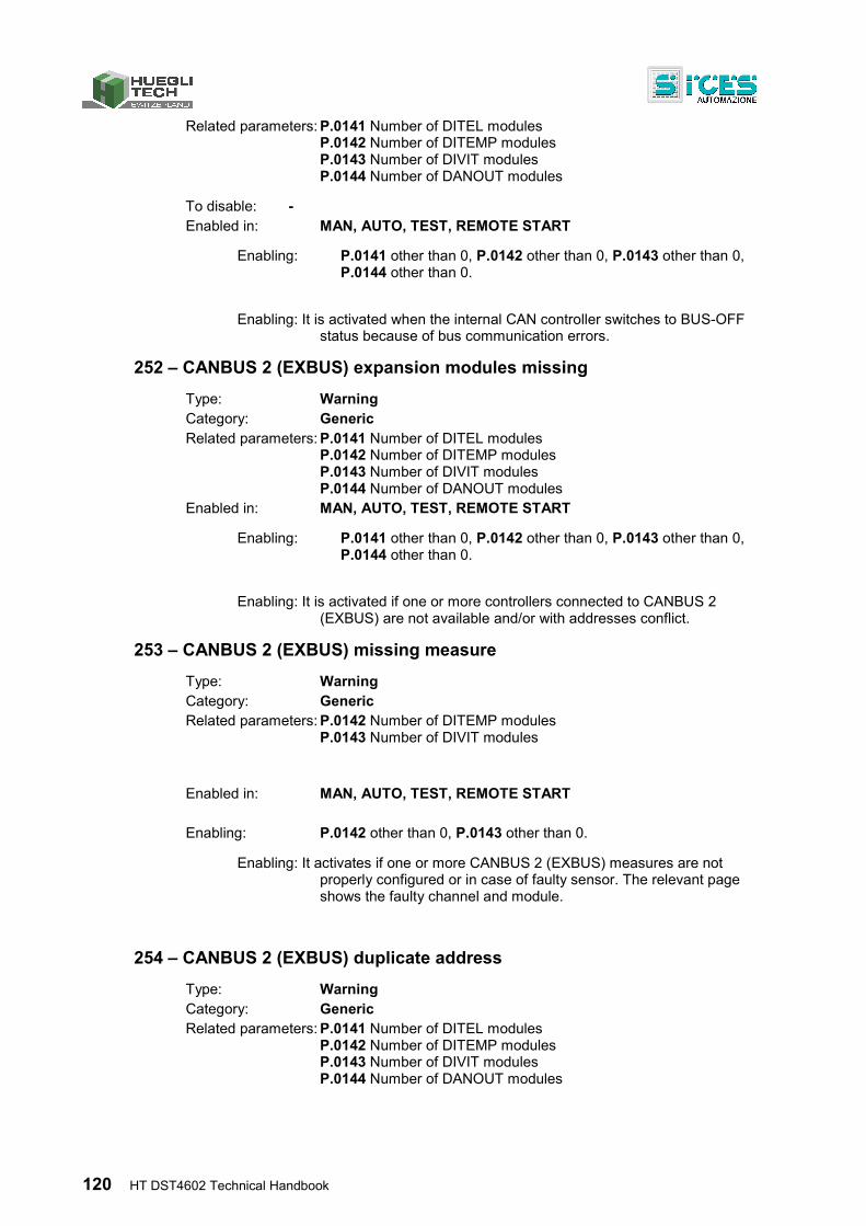
120 HT DST4602 Technical Handbook
Related parameters: P.0141 Number of DITEL modules P.0142 Number of DITEMP modules P.0143 Number of DIVIT modules P.0144 Number of DANOUT modules
To disable: - Enabled in: MAN, AUTO, TEST, REMOTE START
Enabling: P.0141 other than 0, P.0142 other than 0, P.0143 other than 0, P.0144 other than 0.
Enabling: It is activated when the internal CAN controller switches to BUS-OFF status because of bus communication errors.
252 – CANBUS 2 (EXBUS) expansion modules missing
Type: Warning Category: Generic Related parameters: P.0141 Number of DITEL modules
P.0142 Number of DITEMP modules P.0143 Number of DIVIT modules P.0144 Number of DANOUT modules
Enabled in: MAN, AUTO, TEST, REMOTE START
Enabling: P.0141 other than 0, P.0142 other than 0, P.0143 other than 0, P.0144 other than 0.
Enabling: It is activated if one or more controllers connected to CANBUS 2 (EXBUS) are not available and/or with addresses conflict.
253 – CANBUS 2 (EXBUS) missing measure
Type: Warning Category: Generic Related parameters: P.0142 Number of DITEMP modules
P.0143 Number of DIVIT modules
Enabled in: MAN, AUTO, TEST, REMOTE START Enabling: P.0142 other than 0, P.0143 other than 0.
Enabling: It activates if one or more CANBUS 2 (EXBUS) measures are not properly configured or in case of faulty sensor. The relevant page shows the faulty channel and module.
254 – CANBUS 2 (EXBUS) duplicate address
Type: Warning Category: Generic Related parameters: P.0141 Number of DITEL modules
P.0142 Number of DITEMP modules P.0143 Number of DIVIT modules P.0144 Number of DANOUT modules
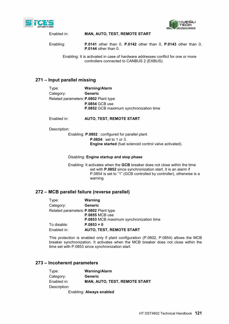
HT DST4602 Technical Handbook 121
Enabled in: MAN, AUTO, TEST, REMOTE START Enabling: P.0141 other than 0, P.0142 other than 0, P.0143 other than 0,
P.0144 other than 0.
Enabling: It is activated in case of hardware addresses conflict for one or more controllers connected to CANBUS 2 (EXBUS).
271 – Input parallel missing
Type: Warning/Alarm Category: Generic Related parameters: P.0802 Plant type
P.0854 GCB use P.0852 GCB maximum synchronization time
Enabled in: AUTO, TEST, REMOTE START Description:
Enabling: P.0802 : configured for parallel plant P.0854: set to 1 or 3.
Engine started (fuel solenoid control valve activated).
Disabling: Engine startup and stop phase
Enabling: It activates when the GCB breaker does not close within the time set with P.0852 since synchronization start. It is an alarm if P.0854 is set to “1” (GCB controlled by controller), otherwise is a warning.
272 – MCB parallel failure (reverse parallel)
Type: Warning Category: Generic Related parameters: P.0802 Plant type
P.0855 MCB use P.0853 MCB maximum synchronization time
To disable: P.0853 = 0 Enabled in: AUTO, TEST, REMOTE START
This protection is enabled only if plant configuration (P.0802, P.0854) allows the MCB breaker synchronization. It activates when the MCB breaker does not close within the time set with P.0853 since synchronization start.
273 – Incoherent parameters
Type: Warning/Alarm Category: Generic Enabled in: MAN, AUTO, TEST, REMOTE START Description:
Enabling: Always enabled
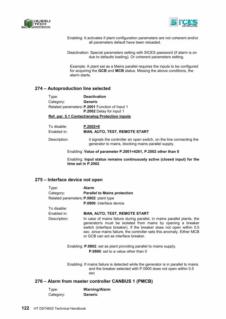
122 HT DST4602 Technical Handbook
Enabling: It activates if plant configuration parameters are not coherent and/or
all parameters default have been reloaded.
Deactivation: Special parameters setting with SICES password (if alarm is on due to defaults loading). Or coherent parameters setting.
Example: A plant set as a Mains parallel requires the inputs to be configured for acquiring the GCB and MCB status. Missing the above conditions, the alarm starts.
274 – Autoproduction line selected
Type: Deactivation Category: Generic Related parameters: P.2001 Function of Input 1
P.2002 Delay for input 1 Ref. par. 5.1 Contact/analog Protection inputs To disable: P.2002=0 Enabled in: MAN, AUTO, TEST, REMOTE START
Description: it signals the controller an open switch, on the line connecting the generator to mains, blocking mains parallel supply.
Enabling: Value of parameter P.2001=4261, P.2002 other than 0
Enabling: Input status remains continuously active (closed input) for the time set in P.2002.
275 – Interface device not open
Type: Alarm Category: Parallel to Mains protection Related parameters: P.0802: plant type
P.0900: interface device To disable: Enabled in: MAN, AUTO, TEST, REMOTE START Description: In case of mains failure during parallel, in mains parallel plants, the
generator/s must be isolated from mains by opening a breaker switch (interface breaker). If the breaker does not open within 0.5 sec. since mains failure, the controller sets this anomaly. Either MCB or GCB can act as interface breaker.
Enabling: P.0802: set as plant providing parallel to mains supply. P.0900: set to a value other than 0
Enabling: If mains failure is detected while the generator is in parallel to mains
and the breaker selected with P.0900 does not open within 0.5 sec
276 – Alarm from master controller CANBUS 1 (PMCB)
Type: Warning/Alarm Category: Generic
HT DST4602 Technical Handbook 123
Enabled in: MAN, AUTO, TEST, REMOTE START Description: This anomaly is forced by the controller MC100 when an anomaly
has to be signaled also to the generators control controllers (the MC100 controller display will show the actual anomaly).
279 – Inconsistent bar voltage
Type: Warning/Deactivation Category: Generic Enabled in: MAN, AUTO, TEST, REMOTE START Description: the controller sets this signal in case a difference is detected
between actual bus-bars voltage and the expected voltage according to status of the breakers, mains and any other generators control controllers connected to PMCB. For example, with at least one more generator GCB closed and the engine started, voltage must be present on bus bars: if the controller does not sense it (through the three phases sensor or a contact), signal is activated after two secs. Signal is usually a warning and switches to alarm only in auto modes after 60 sec. if the controller must close the GCB. The anomaly is not active if the “DROOP” mode has been selected or if an external load sharing unit is set.
Enabling: if the actual bus-bar voltages are different from the theoretic ones
according to breaker and mains status for 2 secs.
280 – System error #001
Type: Warning/Deactivation Category: Generic Enabled in: MAN, AUTO, TEST, REMOTE START Description: controller without a valid serial number (maybe cloned).
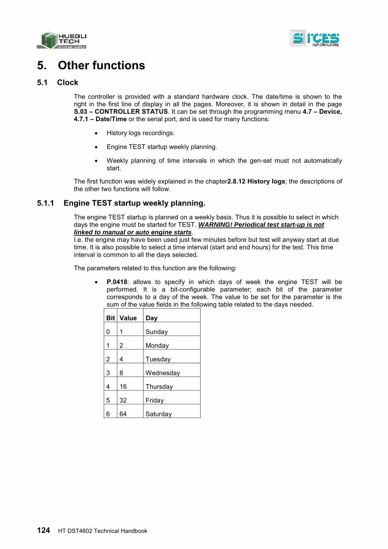
124 HT DST4602 Technical Handbook
5. Other functions 5.1 Clock
The controller is provided with a standard hardware clock. The date/time is shown to the right in the first line of display in all the pages. Moreover, it is shown in detail in the page S.03 – CONTROLLER STATUS. It can be set through the programming menu 4.7 – Device, 4.7.1 – Date/Time or the serial port, and is used for many functions:
History logs recordings.
Engine TEST startup weekly planning.
Weekly planning of time intervals in which the gen-set must not automatically start.
The first function was widely explained in the chapter2.8.12 History logs; the descriptions of the other two functions will follow.
5.1.1 Engine TEST startup weekly planning.
The engine TEST startup is planned on a weekly basis. Thus it is possible to select in which days the engine must be started for TEST. WARNING! Periodical test start-up is not linked to manual or auto engine starts. I.e. the engine may have been used just few minutes before but test will anyway start at due time. It is also possible to select a time interval (start and end hours) for the test. This time interval is common to all the days selected.
The parameters related to this function are the following:
P.0418: allows to specify in which days of week the engine TEST will be performed. It is a bit-configurable parameter; each bit of the parameter corresponds to a day of the week. The value to be set for the parameter is the sum of the value fields in the following table related to the days needed.
Bit Value Day
0 1 Sunday
1 2 Monday
2 4 Tuesday
3 8 Wednesday
4 16 Thursday
5 32 Friday
6 64 Saturday
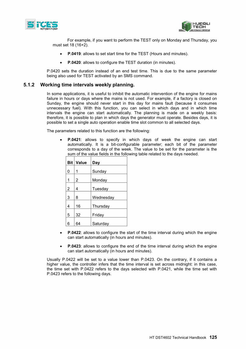
HT DST4602 Technical Handbook 125
For example, if you want to perform the TEST only on Monday and Thursday, you must set 18 (16+2).
P.0419: allows to set start time for the TEST (Hours and minutes).
P.0420: allows to configure the TEST duration (in minutes).
P.0420 sets the duration instead of an end test time. This is due to the same parameter being also used for TEST activated by an SMS command.
5.1.2 Working time intervals weekly planning.
In some applications, it is useful to inhibit the automatic intervention of the engine for mains failure in hours or days where the mains is not used. For example, if a factory is closed on Sunday, the engine should never start in this day for mains fault (because it consumes unnecessary fuel). With this function, you can select in which days and in which time intervals the engine can start automatically. The planning is made on a weekly basis: therefore, it is possible to plan in which days the generator must operate. Besides days, it is possible to set a single auto operation enable time slot common to all selected days.
The parameters related to this function are the following:
P.0421: allows to specify in which days of week the engine can start automatically. It is a bit-configurable parameter; each bit of the parameter corresponds to a day of the week. The value to be set for the parameter is the sum of the value fields in the following table related to the days needed.
Bit Value Day
0 1 Sunday
1 2 Monday
2 4 Tuesday
3 8 Wednesday
4 16 Thursday
5 32 Friday
6 64 Saturday
P.0422: allows to configure the start of the time interval during which the engine can start automatically (in hours and minutes).
P.0423: allows to configure the end of the time interval during which the engine can start automatically (in hours and minutes).
Usually P.0422 will be set to a value lower than P.0423. On the contrary, if it contains a higher value, the controller infers that the time interval is set across midnight: in this case, the time set with P.0422 refers to the days selected with P.0421, while the time set with P.0423 refers to the following days.
126 HT DST4602 Technical Handbook
For example, in case an automatic gen-set start is required only Monday through Friday, between 08:00 and 18:00, you must set:
P.0421=62 (2+4+8+16+32)
P.0422 = 08:00
P.0423 = 18:00
5.2 Thermometer
The controller is provided with a hardware thermometer, for measuring its internal temperature. The temperature is shown at page S.03, multifunction display, last line. It is used for many functions:
At very low temperatures information display slows down. By using the thermometer, when the temperature falls under a very low threshold, the controller switches on the backlight lamp of the display, and this contributes to warm it up and to improve its performances.
The electronic components inside the controller have an extended working temperature range. Despite this, it is possible in critical ambient conditions that temperature goes out of this range. The controller uses the thermometer to activate a warning if the ambient temperature goes over a threshold configurable with parameter P.0366. This is useful for alerting the operator, but is also possible to use a controller configurable output for activating an external cooling system (by using the bit-mapping function you can configure one output to follow the status of the high internal temperature warning).
5.3 Serial number
The controller features a standard software serial number detector. This devices associates a univocal serial number to the controller. Two controllers cannot have the same serial number. This allows unambiguous identification of DTS4602 controllers. The serial number is shown in the multifunction display at page S.03, last line. The SICES password is related to this serial number.
5.4 Fuel pump
Gen-set implements the full management of the fuel pump, to pump fuel from the storage tank to the tank on the generator. The pump can be managed automatically or manually using the controls on the front panel. With the key selector switch in OFF-RESET, MAN, AUTO, TEST, REMOTE START position, select the E.XX“ENGINE MEASURES” mode using the UP▲ and DOWN ▼ buttons. Scroll through the pages using the ◄LEFT or ►RIGHT buttons until you reach page E.06 (FUEL PUMP).
Standard activation procedure: Press the ENTER button to start (operating mode highlighted in negative), and the UP ▲ and DOWN▼ buttons to change the control mode. The following modes can be selected:
MANUAL-ON (pump on - the pump starts and only stops when the max. fuel level is reached, from contact or analog threshold).
HT DST4602 Technical Handbook 127
MANUAL-OFF (pump off).
AUTOMATIC (auto operation of the pump - The pump starts and
stops automatically, controlled by the minimum and maximum level sensors, from contact or thresholds).
Press the ENTER button again to confirm the mode.
Enabling: MAN, AUTO, TEST, REMOTE START modes. Engine running. Digital output set to value 1032-Fuel pump. Input from digital contact or from analog sensor (thresholds set) enabled to acquire fuel level.
Quick activation procedure: an easier and faster method is also available: press the SHIFT and EXIT buttons together to toggle between MAN-ON and MAN-OFF (pressing the buttons will also allow the E.06 page to be displayed).
Buttons selection is ENABLED even though the key is in the OFF-RESET position.
Important! the pump is disabled in OFF/RESET, but only if this mode persists consecutively for five seconds.
5.4.1 Use with an analog level transducer
To use this function requires:
The analog level transducer, connected to the AN. input. INPUT 5 for resistive analog sensor or input AN. INPUT 1 or AN. INPUT 2 if the output sensor (or the DIVIT modules) are powered.
Set the value 1220 or 1221 to acquire measure from the sensor AN.. INPUT 5 or AN. INPUT 1 or AN. INPUT 2 .
Set the value 1032 for the parameter related to the digital output (OUTPUT 1 to OUTPUT 16) used to control the fuel pump.
Set the thresholds to activate/deactivate the pump (parameters P.0402 and P.0403).
If set, also minimum, low and high fuel levels are used (parameters P.0347, P.0345, P.0343).
Important! if the first three conditions are met, the controller will control the pump no matter what the threshold values are.. In particular, the last condition set thresholds are used even though related operation times are set to zero (for disabling anomalies). Very important is the thresholds setting which should be ranked by level (from down up), as follows: minimum, low, start, stop, high. As already explained, the controller operates even if thresholds are not in this order; all you need is the first three ones lower than the last two ones (within each of the two groups they can be swapped, but it is not recommended).
128 HT DST4602 Technical Handbook
5.4.2 Use with a level transducer with contacts
To use this function requires:
Contact level transducer connected to a digital input (INPUT 1 to INPUT 20 or to DITEL modules).
Set the values 3301 and 3302 for the parameters related to fuel pump start and stop digital inputs.
Set the value 1032 for the parameter related to the digital output (OUTPUT 1 to OUTPUT 16) used to control the fuel pump.
If used, set the values 4211, 4212, 4213 for the parameters related to the digital inputs for minimum, low and high fuel level contact acquisition.
Important! if the first three conditions are met, the controller will control the pump no matter what the connected contacts are. In particular, the contacts related to the last connection are used even though relevant operation times are set to zero (for disabling anomalies). So, please pay attention to configuration. Last, contacts must match the following pattern:
Input closed if the level is below the minimum level threshold.
Input closed if the level is below the low level threshold
Input closed if the level is below the pump start threshold
Input closed if the level is below the pump stop threshold
Input closed if the level is over the pump stop threshold
5.4.3 Level evaluation
The controller assigns the actual fuel level by calculating in the order all the following evaluations:
If the level is lower than the pump start threshold, the controller assigns the “start” position.
If a low level threshold exists, and the level is lower than threshold, the controller assigns the “low” position.
If a minimum level threshold exists, and the level is lower than the threshold, the controller assigns the “minimum” position.
If the level is higher than the stop threshold, the controller assigns the “stop” position.
If a maximum level threshold exists, and the level is higher than the threshold, the controller assigns the “maximum” position.
If none of the previous condition is met, the controller assigns the “hysteresis” position.
HT DST4602 Technical Handbook 129
5.4.4 Automatic pump control
Referring to the position evaluated in the previous paragraph, the pump:
Activates if the level is “start”, “low” or “minimum”.
Deactivates if the level is ”stop” or “maximum”.
Retains the actual command if in “hysteresis”.
5.4.5 Manual pump control
Pump can be activated and deactivated according to operator needs. However, the controller prevents the start if the level (see previous paragraphs) is “stop” or “maximum”.
5.4.6 Protections
An “empty store tank” contact can be connected to one of the controller's settable digital inputs. When this input activates, depending on the input management parameter value, you can stop the fuel pump and then set a Warning - 4051, an Unload - 4052, a Deactivation– 4053 or an Alarm – 4053. Moreover, you can set the maximum fuel pump activation time with parameter P.0404. This parameter should be used to set the time needed for the pump to fill the equipment tank, in the worst conditions: empty tank and engine started at maximum power. If the pump is started (either manually or automatically) for more then said time, the controller stops the fuel pump, does not modify the pump operation mode and activates the warning W064: a pump failure or pump not sucking from the store tank is truelike.
5.5 Counters
The controller manages internally the following counters:
1. Resettable active power meter (kWh): it measures only the supplied power and does not measure in case of power reverse.
2. Total Active power meter (kWh): it measures only the supplied power and does not measure in case of power reverse.
3. Reactive power meter (kvarh): resettable to zero, it measures the absolute value.
4. Total Reactive power meter (kvarh): it measures the absolute value.
5. Engine starts counter (resettable to zero)
6. Engine running hours counter (resettable to zero)
7. Total engine running hours counter
8. Time to next service (hours) counter
9. Controller total power supply time (hours) counter
10. Load working time with GCB closed (hours) counter (resettable to zero)
11. Operation hours counter with protection override (resettable to zero).
130 HT DST4602 Technical Handbook
Almost all these counters and meters are displayed on the controller's front panel (only the total supply time counter is not displayed). However, all can be read via the serial port (with the ModBus protocol). Some of these counters can be reset by the operator following a proper procedure, or via the serial port (they are marked in the list with “resettable to zero”). All these counters are saved in a non-volatile memory; therefore they store their values also when the controller is powered off. Non-volatile memories have limited life cycles, therefore reducing memory writing to minimum is required. Therefore, a counter may not be immediately saved as its value changes; consequently, before powering the controller off, ensure to know when and how the counters were saved.
Counters are saved (all together and in the same time) in the following conditions:
immediately after each engine start (with engine running, not after each start attempt).
Immediately after each engine stop (when controller acknowledges the engine stopped status, not when stop is requested).
After each engine running hours counter increase (total, also if the engine has been started for instance six times for ten minutes each time).
After each total engine running hours counter increase (total, also if the engine has been started for instance six times for ten minutes each time).
Each time the load engine working hours counter is increased (total, also if the engine has been started for instance six times for ten minutes each time).
Each time the key switch is turned to OFF/RESET.
For each hour the controller is powered.
When parameter P.0424 is changed (maintenance interval).
Furthermore, counters are saved when they are reset to zero (individually or globally) via front panel or serial port. Note that some counters have a decimal part (for example the minutes-counters associated to hours-counters), which is also saved in a non-volatile memory. Powering off the controller in an uncontrolled way can cause the loss of the decimal part. You will need to switch the key to OFF-RESET to force the controller to save data, before switching off the power.
5.5.1 Counters reset
The reset procedure is common to all counters, but only operates for a counter at a time. All counters are shown at page M.05 and/or E.02. The procedure is the following: press the ENTER button to select the function/selection, press the UP ▲ and DOWN▼ buttons to find the counter to be reset and press the ACK/TEST and EXIT buttons together for at least 5 sec. and/or until the “RESET/DEFAULT” message will be displayed. To delete/exit the page press the EXIT button. The function/selection will exit automatically after 1 min. timeout.
HT DST4602 Technical Handbook 131
5.6 Engine Coolant preheating (heaters)
The controller can monitor the engine cooling temperature in order to activate a heating device in case of very temperature.
To use this function, configure first one of the controller's or DITEL modules digital outputs by setting the value 1031 – Engine coolant preheating for parameter related to the digital output used to control the heating system. Moreover, the controller must be able to acquire the cooling temperature: this can be done via ECU_CANBUS or connecting a temperature analogic transducer connected to the input AN.. INPUT 3 for resistive analog sensor or input AN. INPUT 1 or AN. INPUT 2 if output sensor (or DIVIT modules) is powered and setting the values of parameters 1110 or 1111.
Through parameters P.0355 and P.0356:
P.0355: temperature (in °C) below which the heating system must activate.
P.0356: temperature (in °C) above which the one the heating system must deactivate.
The threshold P.0356 must be set to a value higher than P.0355: the two thresholds guarantee a hysteresis in order to avoid continue turn the heating system on/off due to minimum temperature shifts. The heating activates if the temperature drops below the threshold P.0355 for at least one second; it turns off when the temperature rises above the threshold P.0356 for at least one second.
5.7 Maintenance
The controller can automatically inform the operator about programmed maintenance. This function is configurable with parameters P.0424 and P.0425. With P.0424, it is possible to set extra operation hours for maintenance service. With P.0425 it is possible to set the type of signal to be activated at due time: 1 - Warning, 2 - Deactivation, 4 - Deactivation with power unload or 8 - Alarm (anomaly codes A39 or D39 or U39 or W39).
The function is enabled if the parameter P.0424 contains a value other than zero. The count starts in the moment this parameter is set. When the time configured has elapsed, the controller stores the status of the service request in the non-volatile memory. In this way, also powering the controller off, signalling is not lost and cannot be reset. If an alarm has been selected withy P.0425, then the generator cannot be used again. This function allows to manage rental contracts “by hour number”.
To cancel the maintenance request (and the relevant signal) requires setting again the parameter P.0424: to disable the function, set the parameter to zero; to set the next maintenance after the same period as the previous one, simply confirm the existing parameter; or set a new interval.
Information! To modify these parameters requires installer level password.
132 HT DST4602 Technical Handbook
5.8 Gen-set lock
A command inhibiting gen-set operation can be sent to the controller either through a PC's serial port or a SMS. The locked gen-set can be re-activated either through a PC's serial port or a SMS (powering the controller Off will not work). The controller signals the inhibition status by activating the alarm A12.
5.9 Loads protection from mains breaker damages
Usually, in the case mains is present, the controller releases loads changed-over on it. If for any reasons the breaker closing the loads on mains does not work, loads will remain not connected. This function allows to choose the switching operating mode on the generator loads.
To use this function requires:
That at least one of the configurable controller's inputs acquire the actual mains breaker status (code 3002 for input related parameters).
The time associated with this input be other than zero.
Three operation modes available for enabling delivery after failed MCB closure:
1. P.0221 = 0 does not enable the output due to failed MCB closure
In these cases, if the unit is controlling mains loads closing (GCB already open), but acquires an MCB open status (continuously for the time associated to the input), it will perform the following:
It activates the warning W272 “Mains reverse synchronization failure”
It starts a three attempts sequence to close the MCB (in one of the auto modes)
It activates the warning W13 “MCB not closed”
Engine does not start and loads are in black-out
2. P.0221 = 1 Enables output due to MCB failed closure with black-out on loads
In these cases, if the unit is controlling mains loads closing (GCB already open), but acquires an MCB open status (continuously for the time associated to the input), it will perform the following:
It activates the warning W272 “Mains reverse synchronization failure”
It starts a three attempts sequence to close the MCB (in one of the auto modes)
It activates the warning W13 “MCB not closed”
It does not turn the gen-set Off.
It closes the GCB by powering again the load through the gen-set
HT DST4602 Technical Handbook 133
3. P.0221 = 2 Enables output due to MCB failed closure without black-out on loads
In these cases, if the unit is controlling mains loads closing (GCB not open yet), but acquires an MCB open status (continuously for the time associated to the input), it will perform the following:
It activates the warning W272 “Mains reverse synchronization failure”
It starts a three attempts sequence to close the MCB (in one of the auto modes)
It activates the warning W13 “MCB not closed”
It does not turn the gen-set Off.
Load remains powered by the gen-set.
Now loads will no longer be automatically changed-over on mains. To do this the operator must:
Switch the key to MAN
Change-over manually loads on mains
Switch again key switch to AUTO.
The warning W13 will be immediately disabled and a stop cycle with cooling will be started. Nevertheless, if the mains breaker does not close again, warning will be again activated, the cooling cycle will be interrupted and loads will be again changed-over on gen-set.
Usually, this function is not enabled with the key switched to MAN, and it is disabled if the inhibit input is active.
The warning is activated only if mains is present: this because the breaker is powered by the mains so that, when the mains fails, the status signal will not activate even with the breaker closed.
134 HT DST4602 Technical Handbook
5.10 Engine speed (RPM)
The controller can measure, display and optionally use the engine speed to diagnose the running/stopped engine status, and optionally use to manage an overspeed protection (A18). This measure can be performed either by the engine pick-up signal or by the alternator signal W. In both cases, the signal must be connected to the terminal 7 of connector J27, using the terminal 8 as negative and connecting any cable shield to terminal 9. If the signal W is used, an external filtering circuit will be needed. INFORMATION! The engine speed measure can also be acquired from CAN BUS.
Acquisition of signal configuration is performed through the parameters P.0110 and P.0111. Setting a value different from zero in first parameter enables pick-up management; setting a value other than zero in second parameter, enables W signal management (if both parameters are set, first parameter has priority). To use CAN BUS, both parameters must be set to zero, and the bus enabled (P.0700 other than zero).
Number of teeth of the pick-up wheel must be set in the parameter P.0110. This is a known value and, anyway, easily computed
The ratio between the frequency of signal W and engine speed (expressed in rps.), must be set in the parameter P.0111. This ratio depends on many factors and it is not easy to calculate. If a frequency meter is available, simply start the engine (it will run at is rated and known speed, i.e. 1,500 rpm) and measure the W signal frequency, and then calculate the ratio. If a frequency meter is not available, the following method can be used:
Set a random value for P.0111 (e.g. 15).
Start the engine and, when at operating speed, note the rpm value shown by the controller.
Calculate the ratio between the displayed speed and the actual engine speed (displayed/actual).
Multiply the value previously set in P.0111 by this ratio and set the new value.
Restarting the engine the speed measure should be close to the actual speed. Then, manually adjust the value P.0111 until you get the right display, considering that, for the same true speed, the value displayed by the controller decreases when increasing P.0111. To determine the engine speed, the generator frequency can also be used.
5.11 Load thresholds
INFORMATION! This function must not be mismatched with the “Load function” available for the parallel systems described in the “Parallel functions handbook”.
This function allows to monitor the trend of the active power in order to diagnose:
A low power condition.
A high power condition, to disconnect part of the loads, if needed.
It is necessary to choose a priori the condition to be monitored (using the P.0481 parameter: set it to zero to select the low power monitoring, set it to one to select the high power monitoring).
5.11.1 Low power
INFORMATION! This function is obsolete as widely implemented through the PMCB (see documentation [6]).
Purpose of this function is to diagnose a low power condition (low load) and signaling the problem through a controller's digital output (with more gen-sets in parallel this output could
HT DST4602 Technical Handbook 135
be used to de-activate one or more units). To associate an output to this function, the code 3121 (load thresholds) must be configured in the parameter P.3001 parameter (or following). If no output is configured in this way, the function will not work.
The controller watches the total active power delivered, comparing it with two thresholds (so setting a hysteresis band): the output is activated (signaling the low power condition) if the power drops below the lower threshold for the set time. In the same way, the output is disabled if the power rises above the upper threshold for the set time. These thresholds and delays are set with following parameters:
P.0483: lower threshold (percentage of the rated power P.0106).
P.0484: delay associated to the lower threshold (in seconds).
P.0485: higher threshold (percentage of the rated power P.0106).
P.0486: delay associated to the higher threshold (in seconds).
If the thresholds P.0483 and P.0485 are set to zero or are not congruent, the function will be disabled. To have everything working, the controller must know the actual closing status of the GCB switch. A configured input must be present to acquire this status (code 3001 in parameters P.2001 or following): if missing, the function is not enabled. To start the timing (length configured with the parameter P.0482) during which the output is kept low independently from the power, requires knowing the closing moment. This time allows the system to stabilize before starting to watch powers.
The standard sequence is:
Gen-set startup, generator waiting for operating rate, consent to delivery: in this phase the output is not active.
Waiting for actual closing (acquired from configurable input): in this phase the output is not active.
Wait for the time set in P.0482: in this phase the output is not active.
Power watch: if power drops down for P.0484 seconds below the threshold P.0483 the output is enabled; if it rises for P.0486 seconds above the threshold P.0485 the output is disabled; in the other cases it remains unchanged (hysteresis).
136 HT DST4602 Technical Handbook
5.11.2 High power
Purpose of this function is to diagnose a high power status (high load) to disconnect part of the less important loads. To connect/disconnect the loads use one of the controller settable outputs with code 3121 (load thresholds) configured in the parameter P.3001 (or following). If no output is configured in this way, the function will not work.
The controller watches the total active power delivered, comparing it with two thresholds (so setting a hysteresis band): the output is disabled if the power remains below the lower threshold for the set time. In the same way, the output is enabled if the power rises above the upper threshold for the set time. These thresholds and delays are set with the same parameters of the low load signaling (refer to previous paragraph). The time set with parameter P.0482 is not used.
To have everything working, the controller must know the actual closing status of the GCB switch. A configured input must be present to acquire this status (code 3001 in parameters P.2001 or following): if missing, the function is not enabled.
The output is activated in a maximum power condition, and can directly be used as control for disconnecting loads. Ensure to pay attention to the thresholds: when a part of the loads is disconnected, the power will decrease. If the lower threshold is too high, the output will be disabled, and this could cause the load to be reconnected, with a pendulum effect.
5.12 EJP function
INFORMATION! HT DST4602 is unable to directly track EJP information from the mains. To use this function an external detector must be used. This detector must provide two output signals coherent with said function.
The EJP function allows to start the engine and warm it before mains failure, so when it will happen, loads can be immediately changed-over on gen-set, reducing to the minimum the time the loads remain unsupplied.
The system is based on two signals, available through the mains provider:
A. A signal activated well in advance with respect to the mains failure (e.g. approx 30 mins).
B. A signal activated just before mains failure.
We want to start the engine in (a settable) advance in relation to signal B; however, the load must be taken only when B is active. The controller can perform this operation following the steps below:
A and B signals must remain active until mains reactivates.
Both signals must be connected to relays with exchanging contacts.
The time between A and B signals activation must be known.
To use this function the controller has to be configured in the following way:
Set a digital input to acquire the “REMOTE START MODE” (code 2032 in the P.2001 parameter or equivalent parameters for the other inputs). In addition, this input requires configuring the engine startup delay (in seconds, in the parameter P.2002 or equivalent), since A activates. If, for example, we want to warm the engine for five minutes and the A signal will activate 30 minutes before B, it will require to set 1,500 seconds, i.e. 25 minutes (it is possible to set delays up to 6,000 seconds, i.e. 100 minutes).
Set a digital input to acquire the “INHIBITION OF SUPPLY” (code 2502 in the parameter P.2001 or equivalent parameters for the other inputs).
HT DST4602 Technical Handbook 137
Then connect the NO contact of signal A to first configured input and the contact NC of signal B to second input.
When both signals are inactive, the controller does not receive the remote start request and remains at rest in AUTO mode. The INHIBITION OF SUPPLY contact is skipped.
When signal A activates, both controller inputs will be active. The controller will not immediately shift to REMOTE START mode, but will do only after the time set in P.0508 (or equivalents) is elapsed. So, also in this phase the INHIBITION OF SUPPLY is skipped. In this phase, window S.01 shows the remaining time.
After the time since activation of signal A, the controller shifts to REMOTE START mode and performs the engine start. In this phase, the INHIBITION OF SUPPLY input is no longer skipped, and being it active (connected on contact NC), it will prevent the loads change-over on gen-set.
When signal B activates, the INHIBITION OF SUPPLY input deactivates, allowing the load change-over on gen-set.
When the mains is on, both signals A and B deactivate. Therefore, the controller reverts to AUTO mode, due to mains on, performs the engine stop (with cooling cycle).
5.13 Engine protections OVERRIDE.
For some plant engine protection, loads supply is preferred. Think of hospitals, for example: sometimes, damaging the engine and ensuring power as long as possible, is preferable to saving the engine and leaving the operating rooms without power supply. HT DST4602 can manage these situations: as the engine can be damaged, this function must be requested by a digital input (cannot be activated by parameters). To activate the engine protection OVERRIDE, an input set by the function “2062 – Engine protections override” must be active. When this input is active, the controller shows it in the display window “S.01” and all the engine alarms are switched to warnings:
005: belt break
025: minimum fuel level (from contact).
026: minimum fuel level (from analog measure).
033: maximum coolant temperature (from contact).
034: maximum coolant temperature (from analog measure).
039: maintenance request.
041: minimum oil pressure (from contact).
042: minimum oil pressure (from analog measure).
049: maximum power.
062: CAN-BUS to engine connection failure.
098: engine communication lost.
134: maximum coolant temperature (from CAN-BUS).
135: minimum coolant level (from CAN-BUS).
142: minimum oil pressure (from CAN-BUS).
159: maximum oil temperature (from CAN-BUS).
199: alarms (red lamp) from CAN-BUS.
138 HT DST4602 Technical Handbook
Moreover, also the following generic alarms associated to digital inputs are subject to override (and switch to warning when override is active):
“4014 – Alarm (after oil delay)”.
“4013 – De-activation (after oil delay)”.
“4012 – Unload (after oil delay)”.
“4064 – Alarm (subject to override)”.
In this way the operator receives a signal in case of engine failure, but the generator will keep powering the loads.
The controller manages a separate operating time counter when this OVERRIDE mode is active.
Electrical protections are not affected by the OVERRIDE function.
WARNING: using this function may seriously damage the engine. SICES cannot be held responsible for damages as results of the use of the OVERRIDE function for one or more parameters causing malfunctions and damages to people and/or things.
6. Installation WARNING! :DUE TO INTERNAL HIGH VOLTAGES, THE DEVICE ENCLOSURE MUST BE GROUNDED.
A proper use of the device requires fixed installation in a cabinet or a panel. Accessing device connections shall only be possible by means of specific tools or keys. Device removal shall only be possible by means of tools.
Protection ground must be permanently connected at least to one appropriate terminal.
External installation of overcurrent protection is required for any mains and generator phase. The controller input impedance of any mains and gen-set lines, in normal operating conditions, is greater then 1 Mohm. A 1 A protection threshold is adequate.
The safety heart connection wire must be at least equal in section as the wires used to connect the mains and generator voltage line to the controller. The section of the wire must match the overcurrent protection value used.
For CAT.IV application, the auxiliary low voltage negative supply (GND to J20-1) must be grounded. Otherwise, the operation conditions must be requested to S.I.C.E.S.
For CAT.IV application, the max applicable voltage is 300 Vac (phase-to-neutral) and 520 Vac (phase-to-phase). Maximum voltage to ground is 300 Vac.
For CAT.III application, the max applicable voltage is 345 Vac (phase-to-neutral) and 600 Vac (phase-to-phase). Maximum voltage to ground is 600 Vac.
For CAT.IV application, with GCB contactor powered by the generator, use L1 phase to power the J4-1 terminal.
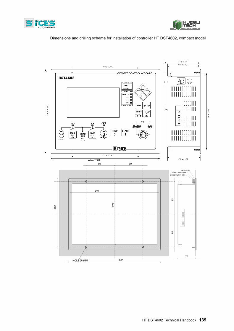
HT DST4602 Technical Handbook 139
Dimensions and drilling scheme for installation of controller HT DST4602, compact model
HOLE Ø 5MM
240
80 80
26070
EXAGONAL NUT 4MASPRING WASHER Ø4
WASHER Ø4
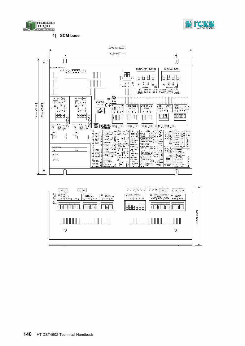
140 HT DST4602 Technical Handbook
1) SCM base

This document is owned by S.I.C.E.S. S.r.l. All rights reserved. S.I.C.E.S. S.r.l. reserves the right to modify this document without prior notice. S.I.C.E.S. S.r.l. has made any effort to ensure that the information herein provide are correct; in any case Huegli-Tech AG does not assume any liability for the use these information.

Huegli Tech AG (LTD)
4900 Langenthal Switzerland Phone: +41(0)629165030
Fax: +41(0)629165035 e-mail: [email protected]
web: www.huegli-tech.com
A product powered by:
S.I.C.E.S. S.r.l. www.sices.eu