Embed Size (px)
Citation preview

Technical Handbook
Sensepoint XCD RFD (Remote Flammable Detector)

Sensepoint XCD RFD Technical Manual SPXCDHMRFEN Issue 4_08-2016
2
1 SafetyEnsure that this Operating Manual is read and understood BEFORE installing / operating / maintaining the equipment. Pay particular attention to Warnings and Cautions. All document Warnings are listed here and repeated where appropriate at the start of the relevant chapter(s) of this Operating Manual. Cautions appear in the sections/sub-sections of the document where they apply
WARNINGSSensepoint XCD RFD is designed for installation and use in Zone 1 or 2 hazardous areas in many countries including Europe, and for Class I, Division 1, Groups B, C & D Hazardous
Areas in the Americas.
Installation must be in accordance with the recognized standards of the appropriate authority in the country concerned.
Access to the interior of the detector, when carrying out any work, must only be conducted by trained personnel.
Before carrying out any work ensure local regulations and site procedures are followed. Appropriate standards must be followed to maintain the overall certiication of the detector.
If using an anti-seize compound, the threads should be thinly coated with an approved silicone free compound e.g. petroleum jelly
To reduce the risk of ignition of hazardous atmosphere, de-classify the area or disconnect the equipment from the supply circuit before opening the detector enclosure. Keep
assembly tightly closed during operation.
Never attempt to open a junction box/enclosure or replace/reit the sensor in potentially hazardous atmospheres while power is still applied to the transmitter.
The detector must be earthed/grounded for electrical safety and to limit the effects of radio frequency interference. Earth/ground points are provided inside and outside the unit. The
internal grounding shall be used as the primary equipment ground. The external terminal is only a supplemental bonding connection where local authorities permit or require such a
connection.Ensure that all screens/instrument earth/clean earth wiring is earthed/grounded at a single
point (either at the controller or detector - BUT NOT BOTH) to prevent false readings or alarms that may occur due to potential earth/ground loops.
Take care when handling sensors as they may contain corrosive solutions.
Do not tamper with or in any way disassemble the sensor.
Do not expose to temperatures outside the recommended ranges.
Do not expose sensors under storage conditions to organic solvents or lammable liquids.
Refer to the local or national regulations relative to the installation at the site. For Europe
see EN60079-29-2, EN60079-14 and EN61241-14.Only assessed for ATEX for ignition hazards.
This equipment is designed and constructed as to prevent ignition sources arising, even in the event of frequent disturbances or equipment operating faults. Note: The control card
must have a suitably rated fuse.The sensor head must be itted with the supplied weather protection, and mounted so that
the sinter is pointing downward to provide ingress protection IPX6.
The weather protection is a potential electrostatic charging hazard. The manufacturer’s instructions should be observed.
(Pour des raisons de securite, Cet equipment doit etre utilise, Entretenu et repare uniquement par un personnel qualifie)
For Safety reasons, this equipment must be operated and serviced
EMI signal may cause incorrect operations.
by qualified personnel only
Any rapid upscale reading followed by a declining or erratic reading may indicate a gas concentration beyond the upper scale limit which may be hazardous.

Sensepoint XCD RFD Technical Manual SPXCDHMRFEN Issue 4_08-2016
3
2 InformationThis manual is for use with the Sensepoint XCD RFD range transmitters only.
The Start-up/Surge/In rush current is dependant on the type of power supply used. The typical start-up current for Sensepoint XCD RFD is less than 800mA. Measure the start-up current using the specific power supply before installation to ensure suitability for your application.
Honeywell Analytics can take no responsibility for installation and/or use of its equipment if not done so in accordance with the appropriate issue and/or amendment of the Technical Manual.
The reader of this Operating Manual should ensure that it is appropriate in all details for the exact equipment to be installed and/or operated. If in doubt, contact Honeywell Analytics for advice.
The following types of notices are used throughout this Operating Manual:
WARNINGIdentifies a hazardous or unsafe practice which could result in severe injury or
death to personnel.
Caution: Identifies a hazardous or unsafe practice which could result in minor injury to personnel, or product or property damage.
Note: Identifies useful/additional information.
Every effort has been made to ensure the accuracy of this document; however, Honeywell Analytics can assume no responsibility for any errors or omissions in this document or their consequences.
Honeywell Analytics would greatly appreciate being informed of any errors or omissions that may be found in the content of this document.
For information not covered in this document, or if there is a requirement to send comments/corrections about this document, please contact Honeywell Analytics using the contact details given on the back page.
Honeywell Analytics reserve the right to change or revise the information supplied in this document without notice and without obligation to notify any person or organization of such revision or change. If information is required that does not appear in this document, contact the local distributor/agent or Honeywell Analytics.

Sensepoint XCD RFD Technical Manual SPXCDHMRFEN Issue 4_08-2016
4
3 Table of contents1 Safety ................................................................................................................................22 Information .......................................................................................................................34 Introduction ......................................................................................................................6
4.1 Transmitter ..................................................................................................................74.2 Flammable Gas sensors .............................................................................................74.2.1 Sensepoint XCD flammable gas sensors ...............................................................84.2.2 Sensepoint LEL Flammable gas sensors ...............................................................84.2.3 705 LEL flammable gas sensors (UL approved) ......................................................94.3 Accessories .................................................................................................................94.4 Options .....................................................................................................................114.4.1 Modbus® ................................................................................................................11
5 Installation......................................................................................................................135.1 Mounting and location ...............................................................................................145.2 Mounting the transmitter ...........................................................................................145.3 Installing the sensor ..................................................................................................15
6 Electrical connections .................................................................................................176.1 Transmitter Wiring .....................................................................................................186.2 Terminal connections ................................................................................................196.3 Power ........................................................................................................................206.4 Cabling ......................................................................................................................216.5 Cable and Earth/Ground regimes .............................................................................216.6 Ground Terminal Wiring ............................................................................................22
7 Default configuration ....................................................................................................238 Normal Operation ..........................................................................................................24
8.1 Display Screen ..........................................................................................................248.2 System Status ...........................................................................................................258.3 Magnetic Wand Activation .........................................................................................268.4 Operation Mode Structure ........................................................................................26
9 First time switch on (Commissioning) ........................................................................2710 Response Check and Calibration ..............................................................................29
10.1 Zeroing and span calibration .................................................................................2911 General Maintenance...................................................................................................33
11.1 Operational Life .......................................................................................................3312 Servicing ......................................................................................................................34
12.1 Sensor replacement ................................................................................................3412.2 Replacing Modules within the Transmitter ..............................................................3612.3 Faults and Warnings ...............................................................................................37
13 Menu’s and Advanced Configuration ........................................................................3813.1 Abort Function .........................................................................................................3813.2 Configuration Mode ................................................................................................3813.3 Sensor / Gas Selection ...........................................................................................4413.4 Review Mode ..........................................................................................................46
14 General specification ..................................................................................................49

Sensepoint XCD RFD Technical Manual SPXCDHMRFEN Issue 4_08-2016
5
15 Ordering information .................................................................................................. 5016 Warranty statement .................................................................................................... 5217 Installation Drawing ................................................................................................... 53
17.1 Mechanical Installation Drawing ........................................................................... 5317.2 Electronic Connection Drawing .............................................................................. 5417.3 Duct Mounting Drawing ......................................................................................... 5617.4 Collecting Cone Drawing ....................................................................................... 5717.5 Mounting Bolt Assy Drawing .................................................................................. 5817.6 Mounting Bracket Drawing ..................................................................................... 5517.7 Sensepoint XCD RFD Sensor ............................................................................... 5917.8 Control Drawing ..................................................................................................... 61
18 Certification................................................................................................................. 6318.1 China GB Ex and PA .............................................................................................. 6318.2 Korea KTL .............................................................................................................. 6618.3 European ATEX ..................................................................................................... 6718.4 International IEC .................................................................................................... 6918.5 Sensepoint XCD ATEX Name Plate ...................................................................... 7118.6 Sensor Cartridges Label ........................................................................................ 72
19 Cross Interference and Cross Calibration ............................................................... 7319.1 Cross Calibration Flammable Gas Detector .......................................................... 7319.2 Meter Multiplication Factors for Sensepoint XCD-IR Propane ............................... 7619.2 Meter Multiplication Factors for Sensepoint XCD-IR Propane ............................... 76
A.1 Modbus® and the XCD .............................................................................................. 77A.2 Modbus® Registers ................................................................................................... 78

Sensepoint XCD RFD Technical Manual SPXCDHMRFEN Issue 4_08-2016
6
LockingGrubscrew
Internal Earth Point
Enclosure
External Earth Point (x2)
M20 or 3/4"NPT cable/conduit entries(x2)
Cover
Seal
Display Module
Terminal Module
Ex d Plug Integral
mounting plate
Certification Label
M25 or 3/4"NPT entry for Flammable Sensor or Remote Sensor Cable Gland
4 IntroductionThe Sensepoint XCD RFD (“Exceed RFD”) transmitter allows the user to either directly or remotely mount a flammable gas sensor from the Sensepoint XCD , Sensepoint and 705 sensor ranges. The remote sensor can be located up to 30 meters (100 feet) from the transmitter. The transmitter features a display and three programmable relays for controlling external equipment e.g. alarms, sirens, valves or switches. The transmitter provides an industry standard 3-wire, 4-20mA source or sink output for connection to a dedicated gas detection control system or PLC.
The construction of Sensepoint XCD RFD allows it to be used in hazardous area locations; it may also be used in other areas not classified as hazardous. Sensepoint XCD RFD is suitable for use in Zone 1 or 2 hazardous areas (International). Calibration and maintenance is carried out using a Magnetic Wand, this allows a single user to undertake routine maintenance without needing to access internal components.
Sensepoint XCD RFD comprises of the main parts as shown below.
Diagram 1. – Exploded View
Sensepoint XCD RFD Technical Manual SPXCDHMRFEN Issue 4_08-2016
7
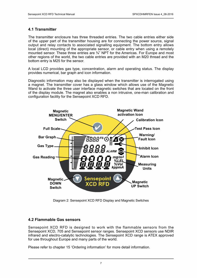
4.1 Transmitter
The transmitter enclosure has three threaded entries. The two cable entries either side of the upper part of the transmitter housing are for connecting the power source, signal output and relay contacts to associated signalling equipment. The bottom entry allows local (direct) mounting of the appropriate sensor, or cable entry when using a remotely mounted sensor. These three entries are ¾” NPT for the Americas. For Europe and most other regions of the world, the two cable entries are provided with an M20 thread and the bottom entry is M25 for the sensor.
A local LCD provides gas type, concentration, alarm and operating status. The display provides numerical, bar graph and icon information.
Diagnostic information may also be displayed when the transmitter is interrogated using a magnet. The transmitter cover has a glass window which allows use of the Magnetic Wand to activate the three user interface magnetic switches that are located on the front of the display module. The magnet also enables a non intrusive, one-man calibration and configuration facility for the Sensepoint XCD RFD.
4.2 Flammable Gas sensors
Sensepoint XCD RFD is designed to work with the flammable sensors from the Sensepoint XCD, 705 and Sensepoint sensor ranges. Sensepoint XCD sensors use NDIR infrared and electro-catalytic technologies. The Sensepoint XCD range is ATEX approved for use throughout Europe and many parts of the world.
Please refer to chapter 15 ‘Ordering information’ for more detail information.
Diagram 2: Sensepoint XCD RFD Display and Magnetic Switches
Measuring Units
Inhibit Icon
Test Pass Icon
Warning/Fault Icon
Magnetic Wand activation Icon
Gas Type
MagneticMENU/ENTER
Switch
MagneticUP Switch
MagneticDOWNSwitch
Gas Reading
Bar Graph
Alarm Icon
Full Scale
Calibration Icon
XCD RFD

Sensepoint XCD RFD Technical Manual SPXCDHMRFEN Issue 4_08-2016
8
4.2.1 Sensepoint XCD flammable gas sensors
Sensepoint XCD flammable gas sensors are ATEX approved for use in Zone 1 or 2 hazardous areas. Two versions are available: IR and CAT versions. For more sensor specific details, refer to the Quick Start Guide of Sensepoint XCD Remote Flammable Sensor (PN: 3001M5022_1). These sensors are not approved for use in the Americas or Canada.
Diagram 3: Sensepoint XCD Flammable Sensor and Plug-in Cartridge
4.2.2 Sensepoint LEL Flammable gas sensors
Standard LEL Version The standard LEL sensor is available for use in temperatures up to 80°C (remote mounting only) and detects gas concentrations up to 100% LEL of a target gas with a resolution in the region of 1% LEL, depending on the gas being detected. The sensor is available with M25 thread. M20 or ¾” NPT threads are options.
High temperature LEL Version The high temperature version is available for use in temperatures up to 150°C (remote mounting only) and ranges of 0-20%LEL or 0-100%LEL depending on transmitter or controller. The sensor is available with M25 thread. M20 or ¾” NPT threads are options.
Details of connecting these sensors with the Sensepoint XCD RFD transmitter are given in sections 5 and 6. For more sensor specific details, refer to the Technical Handbook Part No. 2106M0502 or their individual manuals (Sensepoint HT Sensor Quick Start Guide Part No: 2106M0523, Sensepoint LEL Operating Instructions Part No: 2106M0501). These sensor are not approved for use in the Americas or Canada.
Standard LEL version High Temperature LEL version
Diagram 4: Sensepoint LEL flammable sensors

Sensepoint XCD RFD Technical Manual SPXCDHMRFEN Issue 4_08-2016
9
4.2.3. 705 LEL Flammable gas sensors (UL Approved)
Standard LEL versionThe standard LEL sensor is available for use in temperatures up to 80°C (remote mountingonly) and detects gas concentrations up to 100% LEL of a target gas with a resolution inthe region of 1% LEL, depending on the gas being detected. The sensor is available with¾”NPT thread only.
High Temperature LEL versionThe high temperature version is available for use in temperatures up to 150°C (remotemounting only) and detects gas concentrations up to 100% LEL of a target gas with aresolution in the region of 1% LEL, depending on the gas being detected. The sensor isavailable with ¾”NPT thread only.
Details of connecting these sensors with the Sensepoint XCD RFD transmitter are givenin sections 5 and 6. For more sensor specific details, refer to the 705 Combustible Gas Sensor Operating Instructions Part No: 00705M5002.
Standard LEL version High Temperature LEL version
705 LEL flammable sensors

Sensepoint XCD RFD Technical Manual SPXCDHMRFEN Issue 4_08-2016
10
4.3 Accessories
A range of accessories are available to allow use of Sensepoint XCD RFD in a wide variety of applications. These include Pipe mounting bracket, Sunshade deluge cover,Sensor collecting cone, Sensor flow Housing and Remote sensor mounting junction boxes.
For Sensepoint XCD(P/N: SPXCDWP)
For Sensepoint / 705(P/N: 02000-A-1640/1635) Calibration Cup
Standard Weather Protection
The Standard Weather Protection is designed toprotect the sensor from changes in environmental
conditions. This is recommended to be fitted toa Sensepoint XCD sensor and Sensepoint /
705 sensors.
The Gassing Cap (P/N: S3KCAL) is an optional accessory that may be temporarily fitted to
Sensepoint XCD flammable sensors for Gas Response checking during commissioning and
routine maintenance.
For UL/CSA Junction Box(P/N: 2430-0021)
For ATEX Junction Box(P/N: 00780-A-0100)
For Sensepoint XCD(P/N: SPXCDCC)
For Sensepoint / 705(P/N: 02000-A-1642)
Remote Sensor Mounting Collecting Cone
UL aluminum junction box, ATEX standard junction box and ATEX High temperature junction box (P/N: 2052D0001) are
optional accessories that can be used for remote sensor mounting. Make the connection from the junction box to the transmitter using suitable cable and cable glands.
The Collecting Cone is an optional accessory that may be fitted to the Weather Protection
of XCD and Sensepoint / 705 sensors. The collecting cone is designed for use with
gases that are lighter than air.
Sensepoint Filter and Filter Housing Calibration Gas Flow Housing
Sensepoint Stainless steel filter (P/N: 00780-F-0018) and Filter Housing (P/N: 00780-C-
0038) is an optional accessory can be used to offer additional protection to the Sinter in dry,
and dusty applications.
The Calibration Gas Flow Housing (P/N: 02000-A-1645) may be used for either calibration of the
Sensepoint / 705 sensor or if the Sensepoint / 705 sensor is to be used as part of a Aspirated
Sampling System.

Sensepoint XCD RFD Technical Manual SPXCDHMRFEN Issue 4_08-2016
11
4.4 Options
4.4.1 Modbus®
One of the most common field buses in the industry, the optional Modbus® interface allows the XCD to connect to a bus of devices and transmit data to PLCs or controllers (see Appendix A). Connections to the XCD are made through a pluggable terminal block on the Modbus® interface circuit board. Modbus® RTU protocol uses ASCII/Hex protocols for communication. And allows all transmitter/sensor front panel functions to be transmitted using this industrial fieldbus.
Modbus® protocol is a Master-Slaves protocol. Only one master (at the same time) is connected to the bus and one or up to 32 slave nodes are also connected to the same serial bus. Modbus® communication is always initiated by the master. The slave nodes will never transmit data without receiving a request from the master node. The slave nodes will never communicate with each other. The master node initiates only one Modbus® transaction at the same time.
The MODBUS® may only be used for data collection or record keeping with regard to combustible gas detection and not for performance verification.
Modbus® option is available only for selected gases. Please refer to chapter 15 Ordering information.To find out if a unit has the Modbus® option fitted, look at the part number on the product label. Units fitted with Modbus® have the letter “M” at the end of the part number.
Note: MODBUS® is a registered trademark of Schneider Automation Inc.

Sensepoint XCD RFD Technical Manual SPXCDHMRFEN Issue 4_08-2016
12
(MODBUS ID SETTING)Set id>>Set Modbus slave ID>>Set Baud rate>>Set Parity1) Slave ID shall be set 1~2472) Baud rate setting 9600 or 19200 3) Parity setting (No, Even, Odd) From the Configuration Mode screen, select‘’. To set the Modbus Slave ID, use the up-down ‘’switches to move to the desired position and use ‘’to select it. Again, using the‘’switches, increment or decrement the value until the desired value appears, selects the value and moves to the next setting.
The communications baud rate and Parity Setting can also be set from this screen by using the‘’ switches to navigate to the baud rate display then selecting ‘’. Using the ‘’switches, highlight the proper baud rate or parity setting and select‘’. Default is Slave ID 1, 19200bps and even parity.
Note: Set ID menu is available only for XCD equipped with Modbus® option.

Sensepoint XCD RFD Technical Manual SPXCDHMRFEN Issue 4_08-2016
13
5 InstallationRefer to the Sensepoint XCD RFD Control Drawing 3001EC091 for CSA applications shown in section 17.
WARNINGSSensepoint XCD RFD is designed for installation and use in Zone 1 or 2 hazardous areas
in many countries including Europe, and for Class I, Division 1, Group B,C & D Hazardous Areas in the Americas.
Installation must be in accordance with the recognized standards of the appropriate authority in the country concerned.
Access to the interior of the detector, when carrying out any work, must only be conducted by trained personnel.
Before carrying out any work ensure local regulations and site procedures are followed. Appropriate standards must be followed to maintain the overall certification of the detector.
Care should be taken when removing and refitting the Sensepoint XCD plug-in Sensor to the Sensor Socket so that damage to the connection pins can be avoided.
If using an anti-seize compound, the threads should be thinly coated with an approved silicone free compound e.g. petroleum jelly
To reduce the risk of ignition of hazardous atmosphere, de-classify the area or disconnect the equipment from the supply circuit before opening the detector enclosure. Keep
assembly tightly closed during operation.
Never attempt to open a junction box/enclosure or replace/refit the sensor in potentially hazardous atmospheres while power is still applied to the transmitter.
The detector must be earthed/grounded for electrical safety and to limit the effects of radio frequency interference. Earth/ground points are provided inside and outside the unit. Ensure
that all screens/instrument earth/clean earth wiring is earthed/grounded at a single point (either at the controller or detector - BUT NOT BOTH) to prevent false alarms due to earth/
ground loops.
Take care when handling sensors as they may contain corrosive solutions.
Do not tamper with or in any way disassemble the sensor.
Do not expose to temperatures outside the recommended ranges.
Do not expose sensors under storage conditions to organic solvents or flammable liquids.
Refer to the local or national regulations relative to the installation at the site. For Europe see EN60079-29-2, EN60079-14 and EN61241-14.
Only assessed for ATEX for ignition hazards.
This equipment is designed and constructed as to prevent ignition sources arising, even in the event of frequent disturbances or equipment operating faults. Note: The control card
must have a suitably rated fuse.
The sensor head must be fitted with the supplied weather protection, and mounted so that the sinter is pointing downward to provide ingress protection IPX6.
The weather protection is a potential electrostatic charging hazard. The manufacturer’s instructions should be observed.
The Sensepoint sensor is a possible Electrostatic risk - Do not rub or clean with solvents. Clean with a damp cloth. High velocity airflows and dusty environments can cause
hazardous electrostatic charges.

Sensepoint XCD RFD Technical Manual SPXCDHMRFEN Issue 4_08-2016
14
5.1 Mounting and location
Gas detectors should be mounted where a potential hazard of gas is most likely to be present. The following points should be noted when locating gas sensors.
• When locating detectors consider the possible damage caused by natural events e.g. rain or flooding.
• Consider ease of access to the gas detector for functional testing and servicing.• Consider how escaping gas may behave due to natural or forced air currents.
Note: The placement of gas detectors should be determined following the advice of experts having specialist knowledge of gas dispersion, experts having knowledge of the process plant system and equipment involved, safety and engineering personnel. The agreement reached on the location of detectors should be recorded.
5.2 Mounting the transmitter
The Sensepoint XCD RFD transmitter has an integral mounting plate consisting of four mounting holes on the transmitter body. The transmitter may be fixed directly to a surface mounting, or to a horizontal or vertical pipe/structure, 40.0-80.0mm (1.6 to 3.1 inches) in diameter/cross section. The Pipe Mounting Bracket accessory (optional accessory) may be used for this purpose.
Caution: The location of gas detectors should be made in accordance with any relevant local and national legislation, standards or codes of practice. Always replace sensors
with a sensor of the same type.
Diagram 5: Outline and mounting dimensions
All dimensions are shown in mm.
M20 or 3/4 NPT entries

Sensepoint XCD RFD Technical Manual SPXCDHMRFEN Issue 4_08-2016
15
5.3 Installing the sensor
WARNINGSCare should be taken when removing and refitting the Sensepoint XCD plug-in Sensor to
the Sensor Socket so that damage to the connection pins can be avoided.
If using an anti-seize compound, the threads should be thinly coated with an approvedsilicone free compound e.g. petroleum jelly
Take care when handling old sensors as they may contain corrosive solutions.
Take care when removing or replacing the Sensor Retainer as there may be sharp edgespresent on the adjoining threads.
The equipment is designed and constructed as to prevent ignition sources arising, even in the event of frequent disturbances or equipment operating faults.
Only assessed for ATEX for ignition hazards.
The sensor head must be fitted with the supplied weather protection, and mounted so that the sinter is pointing downward to provide ingress protection IPX6.
The weather protection is a potential electrostatic charging hazard. The manufacturer’sinstructions should be observed.
A remotely mounted sensor should be mounted using a suitable junction box . For further details regarding mounting sensors to suitable junction boxes refer to the relevant sensor manual.
1. Connect the remote sensor/junction box to the Sensepoint XCD RFD transmitter using suitable cable with wires of diameter 0.5 - 2.5mm2 (20AWG - 13AWG).
2. Connect the cable to the transmitter enclosure via the bottom entry. 3. Cable (non conduit) based installations must use appropriately certified cable glands.
Refer to the Sensepoint XCD RFD Control Drawing 3001EC091 shown in section 17 for conduit based installation in the Americas.
Note: The maximum cable length between the remotely mounted sensor and the Sensepoint XCD RFD transmitter is 30 meters (100 feet). The maximum loop resistance is 17 Ω.
4. Terminate the wires from the sensor in the transmitter as shown in chapter 6.2.5. Select sensor type at configuration menu after remote sensor mounting. Refer to the
chapter 12.1 Sensor Replacement and the chapter 13.3.1 Sensor Selection.
Cable Gland Sensor
Transmitter Junction Box
Sensepoint XCD RFD with Sensepoint Remote Sensor

Sensepoint XCD RFD Technical Manual SPXCDHMRFEN Issue 4_08-2016
16
Sensepoint XCD RFD with Sensepoint XCD remote plug-in sensor
It is necessary to use a ferrite filter at the remote sensor to reduce electromagnetic interference. The ferrite filter (supplied) should be fitted as follows:
1. Screw the sensor into the remote junction box.2. Open the ferrite filter.3. Wind the sensor leads 2 turns round the ferrite filter.4. Close the ferrite filter.5. Follow instructions in the individual sensor manuals to complete installation.

Sensepoint XCD RFD Technical Manual SPXCDHMRFEN Issue 4_08-2016
17
6 Electrical connections
WARNINGSSensepoint XCD RFD is designed for installation and use in Zone 1 or 2 hazardous areas
in many countries including Europe, and for Class I, Division 1, Group B,C & D Hazardous Areas in the Americas.
Installation must be in accordance with the recognized standards of the appropriate authority in the country concerned.
Access to the interior of the detector, when carrying out any work, must only be conducted by trained personnel.
Before carrying out any work ensure local regulations and site procedures are followed. Appropriate standards must be followed to maintain the overall certification of the detector.
Care should be taken when removing and refitting the Sensepoint XCD Sensor Cartridge to the Sensor Socket so that damage to the connection pins can be avoided.
If using an anti-seize compound, the threads should be thinly coated with an approved silicone free compound e.g. petroleum jelly
To reduce the risk of ignition of hazardous atmosphere, de-classify the area or disconnect the equipment from the supply circuit before opening the detector enclosure. Keep
assembly tightly closed during operation.
Never attempt to open a junction box/enclosure or replace/refit the sensor in potentially hazardous atmospheres while power is still applied to the transmitter.
The detector must be earthed/grounded for electrical safety and to limit the effects of radio frequency interference. Earth/ground points are provided inside and outside the unit. Ensure that all screens/instrument earth/clean earth wiring is earthed/grounded at a single point (either at the controller or detector - BUT NOT BOTH) to prevent false alarms due to
earth/ground loops.
Take care when handling sensors as they may contain corrosive solutions. Do not tamper with or in any way disassemble the sensor.
Do not expose to temperatures outside the recommended ranges.Do not expose sensors under storage conditions to organic solvents or flammable liquids.
Refer to the local or national regulations relative to the installation at the site. For Europesee EN60079-29-2, EN60079-14 and EN61241-14. For the Americas refer to the Sensepoint
XCD RTD Control Drawing 3001EC091 shown in section 17.

Sensepoint XCD RFD Technical Manual SPXCDHMRFEN Issue 4_08-2016
18
6.1 Transmitter Wiring
The Sensepoint XCD RFD transmitter may be wired in either Current SOURCE or Current SINK configuration. These two options are offered to allow greater flexibility in the type of control system that it can be used with. SOURCE/SINK is selectable via the switch located on the back side of the display module; accessible by removing the display module during installation / commissioning (see section 9).
Caution: All electrical connections should be made in accordance with any relevant local or national legislation, standards or codes of practice.
Caution: 250ohm load resistor (RL) is installed in the factory, In case of connection with controller, this resistor should be removed because controller has load resistor
internally.
Note: Terminate cable screen at detector or controller, not both.
XCD Source 3 Wire 4-20mA (Source)
XCD Sink 3 Wire 4-20mA (Sink)
Controller
+VE
Signal
1
2
3
Detector
+VE
Signal
-VE
RL
-VE
1
3
2
Controller
+VE
Signal
1
2
3
Detector
+VE
Signal
-VE
RL
-VE
1
3
2
RL
Controller
+VE
Signal
1
2
3
Detector
+VE
Signal
-VE -VE
1
3
2
RL
Controller
+VE
Signal
1
2
3
Detector
+VE
Signal
-VE -VE
1
3
2

Sensepoint XCD RFD Technical Manual SPXCDHMRFEN Issue 4_08-2016
19
6.2 Terminal connections
Note: Ensure that none of the wires in the terminal area cause an obstruction when refitting the Display Module. Ensure that the socket on the Display Module is fully engaged in the Display Module Connector on the Terminal Module.
Diagram 6: Sensepoint XCD RFD Terminal module
Terminal Block
Ground/EarthPoint
Power & Signal
Display Module Connector
Display Module Alignment Pin
Locator
Terminal Blockfor Relays
Terminal block for Sensepoint or 705 Flammable sensor
Note: Terminal Blocks are plug/socket type and may be removed to ease wiring.
Terminal Module ConnectionsTerminal Number Marking Connection Description
1 24V +VE Supply(12-32VDC)
Controller Connections2 0V -VE Supply(0VDC)3 4~20mA Current Output Signal4 COM Common
MODBUS RTU. RS485(Optional) 5 TxD MODBUS A(+)
6 RxD MODBUS A(-)7 RLY1/NC Normally Closed
Programmable Relay 1(Default A1)8 RLY1/COM Common
9 RLY1/NO Normally Open10 RLY2/NC Normally Closed
Programmable Relay 2(Default A2)11 RLY2/COM Common
12 RLY2/NO Normally Open13 RLY3/NC Normally Closed
Programmable Relay 3(Default Fault)14 RLY3/COM Common
15 RLY3/NO Normally Open16 +VE Sensitive (Sensor Brown Wire)
RFD Sensor Connection17 -VE Non-Sensitive (Sensor Blue Wire)18 01 Signal (Sensor White Wire)
Table 1: Transmitter terminal connections
Note: The Sensepoint HT sensor and 705 HT sensor (not covered by the CSA certification)must be earthed either at the remote junction box or at the transmitter as appropriate. Avoid earth loops.

Sensepoint XCD RFD Technical Manual SPXCDHMRFEN Issue 4_08-2016
20
6.3 Power for UL/CSA Version
taking into account the voltage drop due to cable resistance.
The maximum loop resistance in the field cable is calculated as follows
R loop = (V controller – V detector min) / I detector
Example;
The controller is supplying a nominal 24Vdc (V controller), the detector minimum allowable voltage is 12Vdc (V detector min), therefore the maximum allowable voltage drop between the controller and detector is 12Vdc; this means a voltage drop of 6V in each core (+ve core and -ve core).
Power consumption of the detector is 5.0W. The current required to drive the detector at the minimum voltage is (I = P / V), 5.0 / 12 = 416.7 mA (I detector).
So, the maximum ieldcable loop resistance (R loop) = 12 / 0.42 = 28.8 Ohms, or 14.4 Ohms per core, (allowing for component variations, losses, etc.).
The following tables show the maximum cable distances between the controller and transmitter assuming a voltage drop of 4V in each core and for different cable parameters. The tables are examples only and actual cable parameters and source power supply voltage for the application should be used to calculate the maximum cable distance allowed at the installation site.
Typical cable data Maximum Cable length (L)Cable size
(cross sectional area)Cable resistance
Ω/km (Ω/mi) Meters Feet
0.5mm2 (20AWG*) 36.8 (59.2) 353 11581.0mm2 (17AWG*) 19.5 (31.4) 666 21851.5mm2 (16AWG*) 12.7 (20.4) 1023 33562.0mm2 (14AWG*) 10.1 (16.3) 1287 42222.5mm2 (13AWG*) 8.0 (12.9) 1621 5318
*nearest equivalent **example for 24Vdc supply voltage
Table 2: Maximum cable distances
+24V+18 V
(wrt Controller 0V)
+6V (wrt Controller 0V)
0V
4-20mA
Field Cable (L)
Signal
Diagram 7: Power Connection
12V (min) ControllerXCD
The Sensepoint XCD transmitter(UL/CSA versions)requires a power supply from the controller of between 12Vdc and 32Vdc. Ensure that a minimum supply of 12Vdc is measured at the sensor,

Sensepoint XCD RFD Technical Manual SPXCDHMRFEN Issue 4_08-2016
21
6.4 Cabling
The use of industrial grade, suitably armoured field cable is recommended.
For example, screened 3 cores (plus screen 90% coverage), suitably mechanically protected copper cable with a suitable M20 explosion-proof gland with 0.5 to 2.5 mm2 (20 to 13 AWG) conductors. Ensure the cable gland is installed correctly and fully tightened. All unused cable entries must be sealed with a suitable certified sealing plug (one plug is supplied).
Remote Mounting Cable Details
Type Cable Spec Max Length
RFD Remote AWM2464 AWG20~AWG14 Shield 30meters
6.5 Cable and Earth/Ground regimes
Effective Earth/Ground bonding is important to ensure good EMC and RFI immunity.
The following diagrams show examples of how to earth/ground bond the cable at enclosures. These bonding techniques provide good RFI/EMC performance. Earth/ground loops must be avoided to prevent the risk of false signal variation.
Cable to Transmitter
Diagram 8: Controller Grounding
Diagram 9: System grounding
Cable outer sheath Cable inner sheath
Clean / Instrument Earth Screen
Controller
Power & Signal
Earth Screen
Controller Transmitter
Note: The Sensepoint HT sensor requires an earth core if the remote junction box does not have a suitable earth point.

Sensepoint XCD RFD Technical Manual SPXCDHMRFEN Issue 4_08-2016
22
The Earth Screen of the field cable should be “tied to Earth” or connected to Ground at one point only. It is common practise to adopt a STAR EARTH connection regime where all instrumentation Screens are connected at one common point.The Screen at the other end of the cable should be “parked” or terminated into a blank terminal.
The following diagrams show how to install the wire into the ground screw of theenclosure.
6.6 Ground Terminal Wiring
Internal Ground connection: Utilize the shield of the wiring cable recommended in thewiring instructions. For connection to this terminal. Twist the shield wire to avoid strayshield wires, Loosen the screw sufficiently and wrap the wire around the screw in a “U” shape. Raise the clamp and place the wire between the clamp and ground base, lower the clamp and tighten the screw to 6.9lb-in torque.
External Ground Connection: If required by local authority, Utilize a No 14 AWG copper, (Stranded or Solid), wire. Loosen the screw sufficiently to enable ‘wrapping the wire around the screw in a “U” shape. Raise the clamp and place the wire between the clamp and ground base, lower the clamp and tighten the screw to10.4lb-in torque. A suitable Ring or Spade type insulated crimp terminal may also be used to accommodate the M4 size external earth screw.
Loosen the bolt Insert cable Fasten the bolt

Sensepoint XCD RFD Technical Manual SPXCDHMRFEN Issue 4_08-2016
23
7 Default configurationThe Sensepoint XCD RFD transmitter is supplied with the following default configuration.Function Value/Setting Meaning
Sensor TypeAutomatic for Sensepoint XCD RFD sensors. Must be set for Sensepoint and 705 sensors.
XCD RFD recognizes the XCD RFD sensor cartridge according to the gas type within its own sensor family i.e. mV. For a Sensepoint and 705 sensor the user must set the sensor type.
Signal output
≥0.0<1.0 mA Fault (refer to table 9 section 12.3 for details) 2.0 mA or 4.0 mA Inhibit (during configuration/user settings)4.0 mA to 20.0 mA Normal gas measurement22.0 mA Maximum over range
Alarm Relay 1*Value is sensor dependant Lower alarm levelDe-energized Energizes on alarmContact Normally Open (NO) Closes on alarm
Alarm Relay 2*Value is sensor dependant Higher alarm levelDe-energized Energizes on alarmContact Normally Open (NO) Closes on alarm
Fault Relay<1mA Detector FaultEnergized De-energizes on alarmContact Normally Open (NO) Closes on alarm
Inhibit 2.0 mA (default) Signal output inhibited during menu use If any relay is set to inhibit relay, then inhibit relay will be activated.
Timeout Disabled
No inhibit timeout. The detector waits for a button press before returning to the previous state/setting Timeout period can be set in ‘Configure Inhibit’ menu in Configuration Mode.
Password 0000 (Disabled) 0000 (Password disabled). If changed then password is activated.
Location(Tag Number) 0000 Optional feature to identify the location or User’s “Tag”
number of the XCD
Temperature oC Option to have oC or oF
Modbus ID, baud rates and Parity bitID : 1 Baud rates : 19,200 Parity bit : EVEN
* Alarm relays automatically reset when reading falls within alarm thresholds. If relay configured to LATCH, then relays must be reset using the Magnetic Wand.
Table 3: Default configuration
Gas Name Default Range Lower Alarm Lower Alarm Type Higher Alarm Higher Alarm
TypeSensepoint Flammable 100%LEL 20%LEL Rising 40%LEL RisingSensepoint HT Flammable 100%LEL 20%LEL Rising 40%LEL RisingSensepoint HT Flammable 20%LEL 10%LEL Rising 15%LEL Rising705 Flammable 100%LEL 20%LEL Rising 40%LEL Rising705 HT Flammable 100%LEL 20%LEL Rising 40%LEL RisingXCD Flammable CB* 100%LEL 20%LEL Rising 40%LEL RisingXCD Methane IR 100%LEL 20%LEL Rising 40%LEL RisingXCD Propane IR* 100%LEL 20%LEL Rising 40%LEL RisingCarbon Dioxide* 2.00%Vol 0.40%Vol Rising 0.80%Vol Rising*Contact Honeywell Analytics for availability
For details of how to change the configuration of the Sensepoint XCD please refer to section 13.

Sensepoint XCD RFD Technical Manual SPXCDHMRFEN Issue 4_08-2016
24
8 Normal OperationSensepoint XCD RFD is supplied configured and ready for use according to the “Default Settings” table shown above. However these setting may be tailored to a specific application requirement using the Sensepoint XCD RFD configuration menu system.
Access to the Sensepoint XCD RFD transmitter’s configuration menus system is via the Magnetic Activation Tool.
8.1 Display Screen
The Sensepoint XCD RFD display features an LCD with Numeric and bar-graph gas concentration data, alpha-numeric warning and status indication, a target for magnetic switch activation and the UP/DOWN/ESC/ENTER zones for remote configuration. The LCD is also backlit with hi-intensity multi-colour LED indicator to show NORMAL, ALARM and FAULT status.
During normal operation the instrument display shows a steady GREEN backlight.
During Low and High Gas Alarm it displays a flashing RED backlight
During Fault condition the instrument display shows a flashing YELLOW backlight.
The screen is visible through the window of the transmitter’s cover. The display shows the gas concentration (both graphically and numerically), range, units, alarm/fault status, etc.
Note: The detector display may become sluggish in sub-zero temperatures and possibly unclear at temperatures below -40 °C, but the detector continues its gas monitoring function. The display is not damaged and recovers when the temperature increases.
Diagram 10: Example of a Flammable Transmitter Display screen – Normal Operation
Test Pass Icon
Gas Type
Gas Reading
Bar Graph (Proportional
Peak Reading bar
to gas reading)
Full Scale
Measuring Unit

Sensepoint XCD RFD Technical Manual SPXCDHMRFEN Issue 4_08-2016
25
8.2 System Status
Display indications, current output and relay states for various operational conditionsare shown in the following table. For further details of error messages and trouble shooting see section 12.3.
System Status
Status Display Current Output Relay BackLightA1 A2 Fault
Fault:Circuit or sensor error
F-XX fault number with fault icon blinking
0-1.0 mA Yellow, flashing
System Fault N/A 0-0.15mANote: In the event of processor failure the watchdog will automatically reset the system for recovery.
Warning
W-XX warning number with fault icon blinking
Dependent on system status
GreenSteady
Normal0.0Gas concentration
4-20 mA GreenSteady
Alarm 1
Gas concentration. 1st alarm icon blinking
4-20 mA Red,
flashing
Alarm 2
Gas concentration. 2nd alarm icon blinking
4-20 mA Red,
flashing
Over-rangeFull scale icon and reading blinking
22mA Red,
flashing
Inhibit
Inhibit icon dependent on Menu command. If any relay is set to inhibit relay, then inhibit relay will be activated.
2 or 4mA depending on configuration.
Green Steady
Table 4: System status

Sensepoint XCD RFD Technical Manual SPXCDHMRFEN Issue 4_08-2016
26
8.3 Magnetic Wand Activation
The magnetic wand is used as a tool to allow the user to communicate with the Sensepoint XCD RFD transmitter. Communication with the XCD RFD is achieved by positioning the Magnetic Wand at one of three different positions on the front glass window of the Sensepoint XCD RFD transmitter. Activation of the switches is verified by observing the Magnetic Wand Activation Icon on the LCD display
Hold the Magnetic Wand in position for up to 2 seconds =
Hold the Magnetic Wand in position for 3 seconds or more =
8.4 Operation Mode Structure
Sensepoint XCD RFD has 3 operating modes.
1. Monitoring mode, is the normal operating status while XCD RFD measures and displays gas concentration. The fault/warning status is periodically checked, relay contacts are activated according to the configuration.
2. Configuration mode, this mode allows parameters relating to the configuration of the Transmitter functions to be changed according to specific needs. This mode can be protected by a password mechanism to prevent unauthorised changes being made.
3. Review mode, allows the user to view the current configuration settings.
Diagram 11: Mode Structure
Further details of the information available and configuration options for the Sensepoint XCD RFD can be found in Section 13. of this manual.
Start - Up
Configuration
Mode
Review Mode
Monitoring
Mode

Sensepoint XCD RFD Technical Manual SPXCDHMRFEN Issue 4_08-2016
27
1. Remove the transmitter housing cover and detach the display unit by lifting the semi-circular handle and pulling the assembly directly away from the termination module (without twisting it)
2. Configure the detector's analogue output signal configuration for Current SINK or Current SOURCE operation using the selector switch located on the back of the display module. The default setting is Current SOURCE.
3. Check that all electrical connections are terminated correctly as per section 6.4. Switch On the external power supply to the transmitter at the safe area gas detection
controller (or PLC).5. Using a Digital Multi Meter (DMM), check the Supply Voltage at the terminals 1 (24V)
and 2 (0V), this should be a minimum supply voltage of 12Vdc (Maximum supply voltage is 32V DC)
6. Switch Off the external power to the detector.7. Refit the Display Module and Cover.
Note: Ensure that none of the wires in the terminal area cause an obstruction when refitting the Display Module. Ensure that the socket on the Display Module is fully engaged in the Display Module Connector on the Terminal Module.
8. Switch On external power to the detector.9. All the display icons/text/numbers are displayed for 3 seconds.
10. A start up sequence will then be displayed, similar to the one shown in Diagram 15.
Note: Calibration is mandatory before the detector can be used for gas monitoring. Refer to Section 10.1 Calibration for the proper procedure.
9 First time switch on (Commissioning)
WARNING
The following procedure requires the Transmitter Cover to be removed while carrying out supply voltage checks. Therefore the appropriate permits to work should be sought in
preparation.
Prior to carrying out any HOT WORK ensure local and site procedures are followed. Ensure that the associated control panel output actuation is inhibited so as to prevent false
alarms.
Caution: The following procedure should be followed carefully and only performed by suitably trained personnel

Sensepoint XCD RFD Technical Manual SPXCDHMRFEN Issue 4_08-2016
28
Diagram 12: Normal Start up procedure (For the Flammable sensor version)
Note:For a full description of each screen shown in Diagram 12, please refer to Section 13.3 “Review Mode” of this Manual.
11. The warm up countdown of 60 seconds (depending on the gas type) is then initiated.12. Normal Monitoring Mode is then resumed.

Sensepoint XCD RFD Technical Manual SPXCDHMRFEN Issue 4_08-2016
29
10 Response Check and Calibration
It is recommended to periodically carry out a gas response check on the Sensepoint XCD
1. A simple Response Check often referred to as a “BUMP TEST” is a test using calibration gas applied to the sensor via the nozzle of the Weather Protection or using the Sensepoint XCD RFD Gassing Cap.If a BUMP TEST is done via the Weather Protection nozzle it may be necessary in windy conditions to increase the flow rate of the test gas by a further 1 LPM, OR, to shelter the weather protection from the wind.
2. A full gas calibration of the sensor as described in the following section, using ONLY theSensepoint XCD Gassing Cap (Part No.: SPXCDDCAL) for the Sensepoint XCD sensor, or,using ONLY the Sensepoint Calibration Gas Flow Housing (P/N: 02000-A-1645) for the Sensepoint and 705 sensor.
10.1 Zeroing and span calibration
Caution: Before initial calibration allow the detector to stabilize for 30 minutes after
applying power. When in zeroing and span calibration mode the current output from the detector is inhibited
(default 2mA) to avoid false alarms. For Flammable gas calibration use a calibration gas concentration of 50%LEL +/-10% for
Canada and US applications and between 25% and 95%LEL for other applications to ensure that the required accuracy can be attained.
HIGH OFF SCALE READINGS MAY INDICATE AN EXPLOSIVE CONCENTRATION.
To calibrate the detector, use an appropriate span gas cylinder, constant flow regulator AND the Sensepoint XCD Gassing Cap (see section 4.3). The flow rates used for calibration gas are as follows:
Gas Type Flow rate (L / Min)Flammable 1 to 1.5
Flammable IR 0.4 to 0.6
A compressed air cylinder (20.9%Vol oxygen) should be used to perform the zero calibration if the area where the detector is located contains any residual amount of the target gas. If no residual gas is present then the background air can be used to perform the zero calibration. Contact your Honeywell Analytics representative for details of suitable calibration kits.
To calibrate the detector follow the procedure below.
RFD to ensure correct operation. This may be done in two ways;
CAUTION: Before each day’s usage, sensitivity must be tested on a known concentration of methane equivalent to 25-50% of full scale concentration. Accuracy must be within 0-20% of actual. Accuracy may be corrected by calibrating the equipment.

Sensepoint XCD RFD Technical Manual SPXCDHMRFEN Issue 4_08-2016
30
(ZERO CALIBRATION)WARNING
When calibrating the Sensepoint XCD Flammable IR or CO2 IR sensors, it is essential that the zero calibration is always followed by a span calibration. The zero calibration must never
be done alone.
1. If the ambient air is NOT considered reliable to use to set the ZERO, then remove the weather protection and fit the Gassing Cap accessory (see Section 4.3) onto the sensor and apply a clean source of zero gas or compressed air.
2. To access the calibration menu, hold the end of the magnet over the switch located at the top center of the detector display () for at least 3 seconds and then remove.
3. The display will indicate the first configuration mode menu ‘SEt CAL’.
4. Put the magnet over the ‘’ switch again and move to enter the Calibration menu.
5. The display will show the current gas reading, and the ‘ ’ icon flashes.
6. When the zero gas reading is stable use ‘’ to confirm zero calibration.
7. If successful the display shows ‘ZEro PASS’ (if not successful, the display shows ‘ZEro FAIL’ and returns to configuration mode).
8. If using zero-air, turn it off. Zeroing is complete and saved.
9. The display shows ‘SPAn’ with ‘YES’ flashing.
10.If span calibration is required use ‘’ proceed to the next step. If span calibration is not required, use ‘’ to select ‘No’ and ‘’ to return to configuration mode.
WARNING
When calibrating the Flammable IR or CO2 IR sensors, it is essential that the span calibration is done after a zero calibration.

Sensepoint XCD RFD Technical Manual SPXCDHMRFEN Issue 4_08-2016
31
(SPAN CALIBRATION)11.The display shows the current calibration span gas concentration while flashing the
‘ ’ icon. Use ‘’ to change the calibration span gas concentration, and ‘’ when required span calibration level is set.
12.The display will show the current gas reading, and the ‘ ’ icon flashes.
13.Connect the regulator to the span gas cylinder.
14.Apply the span gas to the sensor using the Sensepoint XCD Gassing Cap (see section 4.7 for description). The live gas reading is displayed. When the reading is stable, use ‘’ to confirm span calibration.
15.If the sensor has been replaced the following display may be shown.
16.Use ‘’ to select ‘YES’ if the sensor has been replaced or ‘No’ if it has not been replaced.
17.If the span calibration is successful the instrument will briefly display ‘SPAn PASS’ (if fails ‘SPAN FAIL’ displayed and returns to configuration mode).
Note: the calibration due warning counter is reset after a successful calibration. See section 12.3 for further details of setting a calibration due warning.
18.The display alternates between “Purg gAS” and the gas reading to indicate that the unit is expecting the span gas to be removed from the sensor.

Sensepoint XCD RFD Technical Manual SPXCDHMRFEN Issue 4_08-2016
32
19.Promptly switch off the calibration span gas and remove the Sensepoint XCD Gassing Cap from the sensor to allow the gas to disperse.
20.When the reading falls below 50% of the calibration gas level the display indicates a countdown .
21. When the countdown is finished, the calibration procedure is complete.
22. The instrument returns to the ‘Set CAL’ menu. Activate the ‘’ or ‘’ switch to select another menu or select ‘QuIT’ to return to normal monitoring mode.
Note: Remember to always replace the Weather Protection and other accessories.

Sensepoint XCD RFD Technical Manual SPXCDHMRFEN Issue 4_08-2016
33
11 General MaintenanceWARNINGS
Access to the interior of the transmitter, when carrying out any work, must only be conducted by trained personnel.
Care should be taken when removing and refitting the Sensepoint XCD plug-in Sensor Cartridge to the Sensor Socket so that damage to the connection pins can be avoided.
Before carrying out any work ensure local regulations and site procedures are followed. Appropriate standards must be followed to maintain the overall certification of the sensor
and transmitter.
To reduce the risk of ignition of hazardous atmosphere, de-classify the area or disconnect the equipment from the supply circuit before opening the transmitter enclosure. Keep
assembly tightly closed during operation.
Never attempt to open a junction box/enclosure or replace/refit the sensor in potentially hazardous atmospheres.
Take care when handling sensors as they may contain corrosive solutions. Do not tamper with or in any way disassemble the sensor.
Do not expose to temperatures outside the recommended ranges.Do not expose sensors under storage conditions to organic solvents or flammable liquids.
The Sensepoint sensor is a possible Electrostatic risk - Do not rub or clean with solvents. Clean with a damp cloth. High velocity airflows and dusty environments can cause
hazardous electrostatic charges.
For remote Flammable sensors used with the XCD RFD Transmitter, please refer tothe individual sensor manual for specific recommended calibration periods.
11.1 Operational Life
The equipment should be checked following exposure to known contaminants, and recalibrated if necessary.
The pellistors used in the Catalytic flammable gas sensor can suffer from a loss of sensitivity when in the presence of poisons or inhibitors, e.g. silicones, sulphides, chlorine, lead or halogenated hydrocarbons. The pellistors are poison resistant to maximize the operational life of the Catalytic flammable sensor. A typical operating life, subject to the presence of poisons/inhibitors is 36 months.
The NDIR (infrared) flammable gas sensor is not affected by the above-mentioned poisons and therefore has a longer life span. A typical operating life is 5 years.
Refer to section 12 for sensor replacement procedures.

Sensepoint XCD RFD Technical Manual SPXCDHMRFEN Issue 4_08-2016
34
12 Servicing
12.1 Sensor replacement
The sensors that are used with the Sensepoint XCD RFD have no serviceable parts. When they have reached the end of their operational life, simply replace the sensor or the sensor cartridge.
Diagram 13: Sensor Replacement
Only a qualified installation engineer should service the sensor. Ensure power is off before carrying out any maintenance procedures. The only maintenance required is sensor replacement and filter changing (if fitted to an accessory). To replace the complete sensor refer to the Quick Start Guide of Sensepoint XCD Remote Cartridge (PN: 3001M5022_1).
Caution: The following procedure should be followed carefully and only performed by suitably trained personnel.
A fault condition will be signalled by the detector if the sensor is removed with the unit under power.
WARNINGS
Take care when handling sensors as they may contain corrosive solutions. Do not tamper or in any way dis-assemble the sensor. Do not expose to temperatures outside the
recommended range. Do not expose sensor to organic solvents or flammable liquids.
Care should be taken when removing and refitting the Sensepoint XCD plug-in Sensor Cartridge to the Sensor Socket so that damage to the connection pins can be avoided.
Socket Housing
Main body of sensor
Fiter
Black plastic retainer
Sensor Cartridge
Sensor Retainer with locking screw
`

Sensepoint XCD RFD Technical Manual SPXCDHMRFEN Issue 4_08-2016
35
To replace remote sensor of a Sensepoint XCD Flammable Sensor Socket use the following procedure:
1. Important: Remove the Power from the Sensepoint XCD RFD Transmitter2. Remove other accessories from the sensor socket thread.3. Remove the Sensor Retainer with locking screw. 4. Remove the old Sensor Cartridge and replace with a fresh Sensor Cartridge.5. Screw the accessory firmly onto the sensor until it seats against the sensor body
hexagon.6. After fitting the new sensor, reapply power to the XCD RFD transmitter.
Note: It is possible that an F04 fault message may show on the XCD RFD display if the new replacement sensor type does not exactly match with the original sensor it is replacing. In this case, select sensor type from the Configuration menu. Please refer to section 13.3.1 Sensor Selection. Remove the F04 fault message by entering review mode. Refer to section 13.4. Review mode.
7. Select sensor type at configuration menu after remote sensor mounting. Refer to the chapter 13.3.1 Sensor Selection.
8. And then remove fault massage by entering review mode. Refer to the chapter 13.4. Review mode.
WARNING
Ensure that the same Gas Type and Range of Sensor is fitted in place of the old Sensor.
Care should be taken when removing and refitting the Sensepoint XCD plug-in Sensor Cartridge to the Sensor Socket so that damage to the connection pins can be avoided.
The sensor head must be fitted with the supplied weather protection, and mounted so that the sinter is pointing downward to provide ingress protection IPX6.
The weather protection is a potential electrostatic charging hazard. The manufacturer’s instructions should be observed.
CAUTION
The 4-20mA analogue output signal will remain INHIBITED at 2mA (default setting) while the XCD RFD remains in Configuration Mode. However, the ALARM and FAULT RELAYS remain
Active.
Changing the configuration of the Sensor Type or the Gas Star Rating for catalytic sensors may result in temporary activation of the ALARM or FAULT RELAYS.
Should this occur, then recalibrating the sensor will return the XCD RFD to normal condition and reset the relays.
As a precaution, please take necessary action to manually inhibit any external actuator
or alarm devices that are connected to the XCD RFD Alarm/Fault Relays to prevent unnecessary activation during commissioning or reconfiguration of the XCD RFD gas
detector.
To replace the Sensepoint LEL sensor please refer to the Sensepoint Technical Handbook Part No. 2106M0502

Sensepoint XCD RFD Technical Manual SPXCDHMRFEN Issue 4_08-2016
36
12.2 Replacing Modules within the Transmitter
Two replaceable module assemblies are located within the transmitter housing. The Display Module and the Terminal Module.
The Display Module is simply removed by unplugging it from the Terminal Module (this procedure is done during normal installation).
To replace the Terminal Module, use the following procedure:
1. Unscrew and remove the Transmitter Cover
2. Lift the handle and un-plug and remove the Display Module.
3. Unplug the connection terminals and lift them clear of the Terminal Module.
4. Unplug the connector for the XCD sensor.
5. Loosen and remove the three “cross-headed” screws that secure the Terminal Module to the Transmitter housing.
6. Carefully lift the Terminal Module from the transmitter housing.
7. Fit the new Terminal Module using the above procedure in reverse order.

Sensepoint XCD RFD Technical Manual SPXCDHMRFEN Issue 4_08-2016
37
12.3 Faults and Warnings
The table below provides details of possible error.Message Description Action
W-01 Calibration needed
The unit has not been calibrated for the configured calibration intervalCalibration is necessary due to change of sensor/gas type
W-02 Transmitter Temperaturelimits exceeded Use ‘’ to clear when within limits
W-03 Alarm setting needs to be configured
Re-configure alarm settings such that upper alarm should not exceed user configured scale
W-04* Over-range warning Use ‘’ to clear when within limits
W-05*The sensor is switched off to prevent i t f rom being deteriorated
Make sure that there is no flammable gas in the air and use ‘’ to clear when within limits
F-01 Internal I2C failure Cycle power to detector. Replacedetector
F-02 Cell failure For Flammable/IR, cycle power to detector. Replace sensor
F-03 Significant zero drift Re zero/calibrate
F-04 Unexpected sensor fitted Replace sensor
F-05 EEPROM is corrupted Reset transmitter. If fault still appear, replace transmitter
F-06 Low supply voltage Reset transmitter. If fault still appear, replace transmitter
F-07 SRS processor failure Reset transmitter. If fault still appear, replace transmitter
F-08 RAM read/write fault Reset transmitter. If fault still appear, replace transmitter
F-09 Info. memory corrupted Reset transmitter. If fault still appear, replace transmitter
F-10 Code Memory corrupted Reset transmitter. If fault still appear, replace transmitter
F-11 DAC output failure Check load resistor or sink/source mode switch was configured properly
F-12 Heater failure Reset transmitter. If fault still appear, replace transmitter
F-13 Supplied voltage failure Check supply voltage. Replace detector
*Note : W-04 and W-05 are only for flammable catalytic bead sensors. For other gases, gas reading will blink on the LCD instead of the over-range warning.
Table 9: Fault and Warning List
Sensepoint XCD RFD Technical Manual SPXCDHMRFEN Issue 4_08-2016
38
13 Menu’s and Advanced Configuration13.1 Abort Function
In Review Mode or Configuration Mode the user can escape one step back from the current position using the Abort Function. To do this the user must activate the Enter switch for more than 3 seconds with the Magnetic Wand. Switching between each pair of modes or between menus and sub menus are shown in the following table.
From To Example
Review Mode Monitoring Mode Activate Enter switch for more than 3 seconds while in Review Mode
Configuration Mode Monitoring ModeActivate Enter switch for more than 3 seconds while navigating menus in the Configuration Mode
Configuration Mode sub menu
Configuration Mode main menu
Activate Enter switch for more than 3 seconds while in a sub menu
Table 10: Transmitter menu switching
13.2 Configuration Mode
The table below shows the functions available via the configuration menu that can be displayed on the transmitter and accessed using the Magnetic Wand.
The instrument will show the main Menu when the “Enter” switch is activated with the Magnetic Wand and held for at least 3 seconds.
The Menu is password protected to prevent any unauthorized changes. The password is initially disabled and the default password is ‘0000’. If the default password is changed to other than ‘0000’, then the password is enabled automatically and requested when entering Configuration Mode.
With the Menu showing, the following functions can be performed: calibration, bump test, sensor selection and configuration of parameters such as measuring range, calibration gas level, calibration interval, inhibit current, inhibit timeout, alarm setting, relay setting, password change, location setting, temperature unit reading, force analogue output and alarm function checks.
While in Configuration mode, the output current of the transmitter is inhibited to prevent false alarms.
Names, displays and descriptions for each menu item in Configuration Mode are shown in the following table.

Sensepoint XCD RFD Technical Manual SPXCDHMRFEN Issue 4_08-2016
39
Menu Display Description
Set Calibration
Execute zero/span calibrationSet calibration gas levelAfter zero, the option exists to proceed with span calibration, or return to the Menu.
Select SensorSelect the type of sensor from the sensor list. This menu is only available for flammable / IR sensor.
Select Gas
Select the type of gas from the list. This menu is only available for flammable / IR sensor.
Set Range Set measuring range
Configure Inhibit Select inhibit currentSet timeout option (5 minute increments)
Set PasswordEnable/disable passwordSet passwordDefault – no password (Select ‘0000’)
Set Calibration Interval Set calibration interval, 30 to 365 daysUser configurable option to display warning
Bump Test Execute a ‘bump’ test to check gas response of the sensor.
Force CurrentForce analogue output to test functionality of GD control system during system commissioning.
Set Alarms Set alarm 1, alarm 2 levels, functionality and operation (none/falling/rising)
Set Relays
Set relay 1,2,3 type (alarm 1, alarm 2, fault and inhibit) and action (energized/ de-energized)

Sensepoint XCD RFD Technical Manual SPXCDHMRFEN Issue 4_08-2016
40
Relay Operation Configure relay on delay time, relay off delay time and latch/non-latch
Set Location Set location (or TAG number)
Set Temperature Unit Change temperature display unit.°C (Celsius) or °F (Fahrenheit)
Check Alarm functions Simulate alarm situation to check the alarm system without gas present at the sensor
Set ID
Change Modbus® slave ID, baud and parity bit setting (Modbus® version only)
Quit Return to Monitoring mode
Table 11: Transmitter menu descriptions

Sensepoint XCD RFD Technical Manual SPXCDHMRFEN Issue 4_08-2016
41
Diagram 14: Configuration Mode
Menu Switch( > 3 Seconds)
MonitoringMode
Quit/ESC commandAuto quit after no activity of timeout
Abort
Configuration Mode(Inhibited)
Access permitted?
Inhibit mA O/P Yes
No
Set Calibration
Set Range
ConfigureInhibit
Set Password
Set Cal. Interval
Bump Test
Force Current
Set Alarms
Set Relays
Relay Operation
Set Location
Set TemperatureUnit
Test Alarms
Select Gas*
Release mA O/P
Select Sensor*

Sensepoint XCD RFD Technical Manual SPXCDHMRFEN Issue 4_08-2016
42
13.2.1 Configuration mode operation table
Configuration mode allows the user to perform calibration and configure parameters such as full scale range, calibration gas level, calibration interval, inhibit current & timeout, alarm settings, relay settings, set a password, etc. To activate Configuration mode hold the magnet over the ENTER switch for at least 3 seconds and then remove. Configuration mode can be password protected to prevent unauthorized personnel from changing parameters. Initially the password is set to ‘0000’ meaning it is disabled. While in Configuration mode, the output current of the detector is inhibited to prevent false alarms.Use the table below to help navigate the menus and make configuration changes. The menus are shown in the left hand column. Use to select the required menu and ‘’ to enter. Follow the information and instructions in the table from left to right from the required menu.
OK OK OK OK
SEt CAL1
GAS NAME, ZERO CONCENTRATION AND
FLASHING ‘ ’ ICON DISPLAYED. APPLY ZERO GAS AND USE ‘’ WHEN
READING IS STABLE. ‘ZEro PASS’ DISPLAYED IF OK,
‘ZEro FAIL’ IF NOT.
‘SPAN’ DISPLAYED AND ‘YES’ FLASHING TO
ASK IF YOU NOW WANT TO PERFORM SPAN
CALIBRATION. USE ‘’ TO PROCEED OR USE TO SELECT ‘No’
AND RETURN TO MENU MODE.
‘GAS’ TARGET CONCENTRATION FLASHING AND ‘ ’ ICON DISPLAYED.
USE TO CHANGE GAS
CONCENTRATION AND ‘’ TO START
SPAN CALIBRATION.
GAS NAME, CURRENT CONCENTRATION AND
FLASHING ‘ ’ ICON DISPLAYED. APPLY
SPAN GAS AND USE ‘’ WHEN READING STABLE.
IF OK ‘PASS’ & ‘PurG’ DISPLAYED (IF FAIL
‘SPAN FAIL’ DISPLAYED AND RETURNS TO
MENU). REMOVE SPAN GAS. WHEN READING <50% OF SPAN POINT,
COUNTDOWN BEGINS & UNIT RETURNS TO MENU
MODE.
SEt rAn9
BAR GRAPH INDICATING CURRENT RANGE, ‘rAn9’ DISPLAYED & CURRENT
RANGE FLASHES. USE TO SELECT DIFFERENT
RANGE
IF RANGE IS CHANGED, ‘CAL’ DISPLAYED AND
‘YES’ FLASHING TO ASK IF YOU NOW
WANT TO PERFORM CALIBRATION. USE ‘’ TO PROCEED OR USE TO SELECT ‘No’.
IF RANGE IS CHANGED, ‘ALrm’ DISPLAYED AND
‘YES’ FLASHING TO ASK IF YOU NOW WANT TO MODIFY ALARM SETTINGS.
USE ‘’ TO PROCEED OR USE TO SELECT ‘No’ AND
RETURN TO MENU MODE.
UNIT RETURNS TO MENU
MODE
ConF Inhb
‘Inhb’ DISPLAYED WITH ‘ ’ ICON FLASHING. CURRENT INHIBIT mA
VALUE FLASHES. USE TO SELECT NEW VALUE
‘tImE’ DISPLAYED WITH ‘ ’ ICON. FLASHING
CURRENT INHIBIT TIMEOUT PERIOD
(MINUTES) FLASHES. USE TO SET
NEW TIMEOUT. (IF SET TO 0 OUTPUT IS PERMANENTLY
INHIBITED)
UNIT RETURNS TO
MENU MODE
SEt PASS
‘PASS’ DISPLAYED WITH FIRST DIGIT PLACE ICON
OF THE PASSCODE FLASHING. USE TO SELECT 1ST DIGIT OF
CURRENT PASSWORD. USE TO MOVE TO NEXT DIGIT AND SET REST OF
PASSCODE.
UNIT RETURNS TO
MENU MODE
CAL Int32
‘Int’ DISPLAYED WITH CURRENT CALIBRATION
INTERVAL FLASHING. USE TO CHANGE
INTERVAL.
‘duE’ DISPLAYED AND ‘No’, ‘LCd’ OR ‘ALL’
FLASHING. USE TO SELECT REQUIRED
CAL DUE WARNING OUTPUT.
UNIT RETURNS TO
MENU MODE

Sensepoint XCD RFD Technical Manual SPXCDHMRFEN Issue 4_08-2016
43
bumPtESt
PEAK READING DISPLAYED WITH OUTPUT INHIBITED ‘ ’ ICON AND PEAK STRING FLASHING.
APPLY BUMP TEST GAS AND CHECK PEAK READING ON DISPLAY.
CURRENT GAS CONCENTRATION DISPLAYED WITH
OUTPUT INHIBITED ‘ ’ ICON FLASHING.
UNIT RETURNS TO
MENU MODE
Forc Curr
‘Forc’ DISPLAYED WITH ‘’ ICON. DEFAULT FORCE
CURRENT ‘4.00’ FLASHES. USE TO CHANGE TO
REQUIRED mA LEVEL.
UNIT TRANSMITS THE CURRENT
IF YOU WANT TO EXIT FROM THIS MENU, USE
ABORT FUNCTION
SEt ALrm
‘AL1’, ICON DISPLAYED AND CURRENT ALARM
LEVEL 1 CONCENTRATION FLASHES. USE TO CHANGE TO REQUIRED
CONCENTRATION LEVEL.
‘AL1’ DISPLAYED WITH ‘NonE’, ‘rISE’ OR ‘FALL’ FLASHING. USE
TO SELECT REQUIRED ALARM ACTION.
‘AL2’, ICON DISPLAYED
AND CURRENT ALARM LEVEL 2
CONCENTRATION FLASHES. USE TO CHANGE
TO REQUIRED CONCENTRATION
LEVEL.
‘AL2’ DISPLAYED WITH ‘NonE’, ‘rISE’ OR ‘FALL’ FLASHING. USE
TO SELECT REQUIRED ALARM ACTION AND USE ‘’ TO RETURN TO MENU
MODE.
SetrLY
‘rL1’ DISPLAYED AND ‘AL1’, ‘AL2’, ‘Inht’ or ‘FLt’ FLASHES. USE TO CHANGE TO REQUIRED
RELAY TARGET.
‘rL1’ DISPLAYED AND ‘dEEn’ or ‘Enr9’
FLASHES. USE TO CHANGE TO REQUIRED
RELAY ACTION.
‘Rl2’ DISPLAYED AND ‘AL1’, ‘AL2’, ‘Inht’ or ‘FLt’ FLASHES. USE TO CHANGE TO REQUIRED RELAY
TARGET.
‘rL2’ DISPLAYED AND ‘dEEn’ or ‘Encr9’ FLASHES.
USE TO CHANGE TO REQUIRED RELAY
ACTION.
‘rL3’ DISPLAYED AND ‘AL1’, ‘AL2’, ‘Inht’ or ‘FLt’ FLASHES. USE TO CHANGE TO REQUIRED
RELAY TARGET.
‘rL3’ DISPLAYED AND ‘dEEn’ or ‘Enr9’
FLASHES. USE TO CHANGE TO REQUIRED
RELAY ACTION.
UNIT RETURNS TO
MENU MODE
rlYOPr
‘rLY’, ‘ON’ DISPLAYED AND CURRENT RELAY-ON TIME
FLASHES. USE TO CHANGE TO REQUIRED
RELAY-ON DELAY.
‘rLY’, ‘OFF’ DISPLAYED AND CURRENT RELAY-
OFF TIME FLASHES. USE TO CHANGE TO REQUIRED RELAY-
OFF DELAY.
‘Ltch’ DISPLAYED AND ‘YES’ or ‘No’
FLASHES. USE TO CHANGE TO
REQUIRED LATCH OPTION.
UNIT RETURNS TO MENU
MODE
SetLoc
‘Loc’ DISPLAYED WITH FIRST 4 CHARACTERS OF THE LOCATION STRING. USE TO CHANGE THE
1ST CHARACTER OF CURRENT LOCATION
STRING. USE TO MOVE TO NEXT CHARACTER
AND SET REST OF STRING. MAXIMUM 12 CHARACTERS CAN BE
SET.
‘Loc’ DISPLAYED NEW LOCATION STRING. THE STRING MOVES RIGHT-
TO-LEFT TO SHOW WHOLE CHARACTERS
TWICE. THEN UNIT AUTOMATICALLY
RETURNS TO MENU MODE.
tEmPUnIt
‘tEmP’ DISPLAYED WITH ‘°C’ OR ‘°F’ FLASHING.
USE TO CHANGE TO REQUIRED TEMPERATURE
UNIT.
UNIT RETURNS TO
MENU MODE
tEStALrm
‘Forc’ DISPLAYED and ’AL1’ FLASHING TO SELECT
TEST-REQURED ALARM. USE ‘’ TO FORCE
ALARM1.
GAS NAME, CURRENT GAS CONCENTRATION
DISPLAYED AND ‘’ ICON AND AL ICON
FLASHE.
UNIT RETURNS TO
MENU MODE
9uIt QUITS MENU MODE AND
RETURNS TO MONITORING MODE
OK OK OK OK 1 Refer to section 10.1 for detailed zero and span calibration procedures. Re-calibrate the detector if left un-powered for periods in excess of 24 hours.2 The calibration due warning counter is automatically reset after a successful calibration.
Table 12. Configuration Mode Operation

Sensepoint XCD RFD Technical Manual SPXCDHMRFEN Issue 4_08-2016
44
13.3 Sensor / Gas Selection
13.3.1 Sensor Selection
“Select Sensor” sets the identity of the type of mV sensor attached to the XCD RFD when it does not detect the sensor type automatically.
The available mV sensors:Cb-2 Sensepoint HT 20%LEL remote Cb-3 Sensepoint HT 100%LEL remote Cb-4 Sensepoint 100%LEL remote Cb-5* Flammable CAT 0-100%LEL remote Cb-6 705 100%LEL remote (CSA Certified)Cb-7 705 HT 100%LEL remoteIr-5* Carbon Dioxide IR 0-2%VOL only remote Ir-7 Methane IR 0-100%LEL remote Ir-8* Propane IR 0-100%LEL remote
Selecting ‘’ will move the operator to the Select Sensor screen. The first screen displays the currently configured sensor. To select a new mV sensor like remote type sensors (Ir-7, Cb-3 and Cb-4), use‘’ to move through the list, and then use ‘’ to make the selection or discard the selection and return to menu mode by using abort function. If type of sensor is changed, calibration prompt will appear to ask if you want to perform calibration.
Diagram 15: Sensor Selection
13.3.2 Gas Selection
Use “SEL gAS” to set the target gas for sensors capable of detecting multiple gases. The available gases:
Sensor type Gas type Gas Name displayedCb-3 Str 1 to Str 8 FLMCb-4 Str 1 to Str 8 FLMCb-5* Str 1 to Str 8 FLMCb-6 Str 1 to Str 8 FLMCb-7 Str 1 to Str 8 FLM

Sensepoint XCD RFD Technical Manual SPXCDHMRFEN Issue 4_08-2016
45
Ir-5* CO2 CO2Ir-7 Methane mEtIr-8* Propane ProP
*Contact Honeywell Analytics for availability
Gas selection is dependent on the type of sensor attached to the XCD RFD. If Ir-7 sensor is attached, then a user can only select ‘mEt’ gas respectively. But when Cb-3/Cb-4 sensor is attached to the XCD RFD, a user can select the gas from Str1 (1*) to Str8 (8*). For more information on star rating, please refer to section 19.2.
The current configuration of the XCD RFD is displayed and by using the ‘’ switch to enter “SEL gAS” menu. To select a flammable gas, use ‘’ to move through the list, and then use ‘’ to make the selection or abort function to discard the selection and return to menu mode.
If type of gas is changed, calibration prompt will appear to ask if you want to perform calibration.
...
Diagram 16: Gas Selection
CAUTION
The 4-20mA analogue output signal will remain INHIBITED at 2mA (default setting) while the XCD RFD remains in Configuration Mode. However, the ALARM and FAULT RELAYS remain
Active.
Changing the configuration of the Sensor Type or the Gas Star Rating for catalytic sensors may result in temporary activation of the ALARM or FAULT RELAYS.
Should this occur, then recalibrating the sensor will return the XCD RFD to normal condition and reset the relays.
As a precaution, please take necessary action to manually inhibit any external actuator or
alarm devices that are connected to the XCD RFD Alarm/Fault Relays to prevent unnecessary activation during commissioning or reconfiguration of the XCD RFD gas detector.
For CSA Certified applications, use CB-6 calibrated only to Methane.

Sensepoint XCD RFD Technical Manual SPXCDHMRFEN Issue 4_08-2016
46
13.4 Review Mode
The instrument will enter Review mode when the “Enter” switch is activated with the Magnetic Wand and held for around one second.
Names, displays and descriptions for each review item in Review Mode are shown in the following table.
Software version
SRS version
EEP version
Gas
Measuring range
Calibration level
Calibration due
Alarm 1
Alarm 2
Item name Display Description
S/W version of transmitter
S/W version of SRS (watch dog)
EEPROM parameter version
Gas type
A user selected measuring range
Calibration gas level
Estimated time to next calibration
Alarm settings for Alarm 1
Alarm settings for Alarm 2

Sensepoint XCD RFD Technical Manual SPXCDHMRFEN Issue 4_08-2016
47
Location
Power
Temperature
Peak conc.
Test Result
Location in which the transmitter is installed
Power voltage*
Internal Transmitter temperature*
Maximum concentration detected up to now
There is no fault detected.
Table 13: Transmitter menu descriptions
Note:*Power voltage and internal transmitter temperature may be different from actual value due to measuring accuracy and internal heating components.

Sensepoint XCD RFD Technical Manual SPXCDHMRFEN Issue 4_08-2016
48
Diagram 17: Review Mode
MonitoringMode
ReviewMode
Menu Switch(1s to 3s)
Auto end to cycleS/W Version
Measuring Range
Calibration Gas Level
EEPROM Version
2 second delay
2 second delay
2 second delay
2 second delay
Calibration Due
2 second delay
Test Result
2 second delay
Peak Reading
Temperature
2 second delay
2 second delayGas Type Supplied input voltage
2 second delay
Location
2 second delay
SRS Version
Alarm Setting
2 second delay
2 second delay

Sensepoint XCD RFD Technical Manual SPXCDHMRFEN Issue 4_08-2016
49
14 General specification
Sensepoint XCD TransmitterUse 3-wire, 4-20mA, gas detector transmitter for use with remotely mounted flammable gas
detectors.Electrical
Input Voltage Range: Max Power Consumption:
Current output≥0.0<1.0 mA4.0 mA to 20.0 mA2.0 mA or 4.0 mA22.0 mATerminals
Relays
Communication
12 to 32Vdc (24Vdc nominal) Max 5 Watts. at 24Vdc (see section 2 regarding maximum in rush current) 4-20mA (Source or Sink) Fault (refer to table 5 section 12.3 for further details)Normal gas measurementInhibit (during configuration/user settings)Maximum over range15 x screw terminals suitable for wire diameter 0.5mm2 to 2.5mm2 (20AWG to 13AWG).3 x 5A@250VAC. Selectable normally open or normally closed (switch) and energized/de-energized (programmable).RS485, Modbus RTU
ConstructionMaterial Epoxy painted aluminium alloy or 316 Stainless SteelWeight Aluminium alloy: 1.7kg, 316 Stainless Steel: 3.7kgMounting Pole or wall mountingCable Entries 2 x M20 (for ATEX/IECEx/AP Approval) , or 2 x 3/4"NPT (for cCSAus Approval)Sensor Entry M25 (for ATEX/IECEx/AP Approval) or 3/4"NPT (for cCSAus Approval)Detectable Gases & Performance (See notes below)
Gas Selectable FullScale Range
DefaultRange
Steps SelectableCal GasRange
Default Cal
Point
ResponseTime (T60)
Secs
ResponseTime (T90)
Secs
Accuracy Operating Temperature Default Alarm Points
Min Max A1 A2
Sensepoint Standard Temperature Sensor
25 to 95% ofselected fullscale range
Flammable 1 to 8* 20 to 100%LEL 100%LEL 10%LEL 50%LEL <25 <+/- 1.5%LEL -55°C / -67°F 80°C / 176°F 20%LEL 40%LEL
Sensepoint High Temperature SensorFlammable 1 to 8* 20%LEL 20%LEL n/a 10%LEL <25 <+/- 1.5%LEL -55°C / -67°F 150°C / 302°F 10%LEL 15%LELFlammable 1 to 8* 20 to 100%LEL 100%LEL 10%LEL 50%LEL <10 <+/- 1.5%LEL -55°C / -67°F 150°C / 302°F 20%LEL 40%LEL
Plug-in Sensepoint XCD Catalytic Bead SensorsFlammable 1 to 8* * 20 to 100%LEL 100%LEL 10%LEL 50%LEL <6 <25 <+/- 1.5%LEL -20°C / -4°F 55°C / 131°F 20%LEL 40%LELPlug-in Sensepoint XCD Infrared Sensors
30 to 70% ofselected fullscale range
Methane 20 to 100%LEL 100%LEL 10%LEL 50%LEL <40 <+/- 1.5%LEL -20°C / -4°F 50°C / 122°F 20%LEL 40%LELPropane* 20 to 100%LEL 100%LEL 10%LEL 50%LEL <40 <+/- 1.5%LEL -20°C / -4°F 50°C / 122°F 20%LEL 40%LEL
Carbon Dioxide* 2.00%Vol 2.00%Vol. n/a 1.00%Vol. <40 <+/-0.04%Vol. -20°C / -4°F 50°C / 122°F 0.40%V/V. 0.80%V/V.*Contact Honeywell Analytics for availability - Rising Alarm - Falling AlarmNOTESPerformance figures are taken at 20-25°C;1. measured using a sample humidity of 50%RH, applicable between 10 and 90% of full scale,2. measured using test units calibrated at 50% of full scale,3. measured at 1000cc/min for Methane CAT, 500cc/min for Methane IR with calibration cup (S3KCAL).
Response time (T90) may increase when operating in lower or higher temperature conditions or when gas is introduced with the Weather Protection accessory (SPXCDWP) fitted. Methane IR sensor is calibrated and linearised only for Methane. Should it be exposed to other HC then non linear response is expected. For linearised operation other than Methane contact HA for alternate parts.Methane IR is calibrated at the factory 50%LEL Methane (2.5%Vol). This calibration enables 100% functional test prior to dispatch. This calibration does not remove need for calibration & test as part of commissioning at site. For gases other than Methane the unit has to be calibrated at site using target gas.Data represents typical values, and system conditioning may be required to achieve stated result.Contact HA for details.* Extended operating temperature range of -40°C to +65°C (-40°F to +149°F) for all sensor except for IR, with an accuracy of +/- 30% of applied gas from -20°C to -40°C (-4°F to -40°F) and +55°C to +65°C (+131°F to +149°F). Long term operation at this range may cause decline in sensor performance.Contact Honeywell Analytics for any additional data or details.
CertificationChina GB Ex d IIC T4 GB3836.1&2 -2000, PA, CCCFKorea KTL Ex d IIC T6 (-40ºC to +65ºC)European ATEX Ex II 2 GD Ex d IIC Gb T6(Ta -40ºC to +65ºC) Ex tb IIIC T85ºC Db IP66International IEC Ex II 2 GD Ex d IIC Gb T6(Ta -40ºC to +65ºC) Ex tb IIIC T85ºC Db IP66North America cCSAus Class I, Division 1, Groups B, C & D/ Flammable Performance CSA C22.2 No.152 and ISA 60079-29-1(Only combustion gas detection portion of the instrument has been assessed)
CE EN50270:2015 EN6100-6-4:2007EnvironmentalIP Rating IP66 in accordance with EN60529:1992, NEMA 4X (Tested by third party laboratory)Operating Temperature -40ºC to +65ºC/ -40ºF to +149ºF, (IR: -20ºC to +50ºC/ -4ºF to +122ºF)
Note: The detector display may become illegible at temperatures below -20°C, but the detector continues its gas monitoring function. The display is not damaged and recovers when the temperature rises back above -20 °C.
Operating Humidity Continuous 20-90%RH (non condensing), Intermittent 10-99%RH (non condensing)Operating Pressure 90-110kPaStorage Conditions -25°C to +65°C (-13°F to +149°F)

Sensepoint XCD RFD Technical Manual SPXCDHMRFEN Issue 4_08-2016
50
15 Ordering information
Part number Description
Sensepoint XCD RFD transmitter (LM25)
SPXCDALMRFD ATEX/IECEx/AP* approved SP XCD RFD Transmitter with LM25, M20 Entry, without MODBUS
SPXCDULNRFD cCSAus approved SP XCD RFD Transmitter with LM25, 3/4“NPT Entry, without MODBUS
SPXCDALMRFDM ATEX/IECEx/AP* approved SP XCD RFD Transmitter with LM25, M20 Entry, with MODBUS
SPXCDULNRFDM cCSAus approved SP XCD RFD Transmitter with LM25, 3/4“NPT Entry, with MODBUS
Sensepoint XCD RFD transmitter (316SS)
SPXCDASMRFD ATEX/IECEx/AP* approved SP XCD RFD Transmitter with 316SS
SPXCDUSNRFD cCSAus approved SP XCD RFD Transmitter with 316SS, 3/4“NPT Entry, without MODBUS
SPXCDASMRFDM ATEX/IECEx/AP* approved SP XCD RFD Transmitter with 316SS, M20 Entry, with MODBUS
SPXCDUSNRFDM cCSAus approved SP XCD RFD Transmitter with 316SS, 3/4“NPT Entry, with MODBUS
Replacement Sensepoint XCD sensor cartridge
SPXCDXSFXSS** Flammable CAT 0-100%LEL (20,0 to 100.0%LEL)
SPXCDXSRXSS Methane IR 0-100%LEL (20,0 to 100.0%LEL)
SPXCDXSPXSS** Propane IR 0-100%LEL (20,0 to 100.0%LEL)
SPXCDXSB1SS** Carbon Dioxide IR 0-2.00%VOL only
Remote Flammable Sensor (XCD Sensor Cartridge + Socket Housing)
SPXCDXSRFXSS** Flammable CAT 0-100%LEL (20,0 to 100.0%LEL)
SPXCDXSRRXSS Methane IR 0-100%LEL (20,0 to 100.0%LEL)
SPXCDXSRPXSS** Propane IR 0-100%LEL (20,0 to 100.0%LEL)
SPXCDXSRBXSS** Carbon Dioxide IR 0-2.00%VOL only
Replacement Sensepoint Sensor
2106B1200 Standard LEL Version , -55°C to +80°C, M20 version, ATEX Certification
2106B1201 Standard LEL Version, -55°C to +80°C, M25 version, ATEX Certification
2106B1204 Standard LEL Version , -55°C to +80°C, 3/4 NPT version, ATEX Certification
00705-A-1733 Standard LEL Version, -55’C to +80’C, Aluminium, 3/4NPT Version, UL Certification
2106B2310 High temperature LEL Version, -40°C to +150°C, M20 version, ATEX Certification
2106B2311 High temperature LEL Version, -40°C to +150°C, M25 version, ATEX Certification
2106B2312 High temperature LEL Version, -40°C to +150°C, 3/4 NPT version, ATEX Certification
00705-A-1735 Standard LEL Version, -40’C to +150’C, Aluminium, 3/4NPT Version, UL Certification
Sensepoint XCD Accessories
S3KCAL Calibration cap
SPXCDWP Weather Protection
SPXCDCC Collecting cone for use with lighter than air gases
SPXCDDMK Duct mounting kit
SPXCDMTBR Pipe Mounting bracket (inc. fixings and hex wrench set)
SPXCDSDP Sunshade / Deluge Protection
SPXCDHMRFEN Hard Copy Manual in English
Sensepoint / 705 Accessories
2430-0021 UL/CSA Aluminum 3 wire Junction Box Assembly
00780-A-0100 ATEX/IECEx Junction Box (3) M20, (1) M25 entries.
2052D0001 ATEX High Temperature Junction Box.
02000-A-1642 Collecting Cone
02000-A-1645 Calibration Gas Flow Housing for Sensepoint Sensors
00780-A-0035 Calibration Gas Flow Housing for 705 Sensors00780-A-0076 Weather Protection Stainless Steel for high temps.

Sensepoint XCD RFD Technical Manual SPXCDHMRFEN Issue 4_08-2016
51
02000-A-1640 Nylon Weather Protection Housing for Sensepoint Combustible Sensors
02000-A-1635 Weather Protection Housing for 705 Sensors
1283-1047 Duct Mount Adaptor Assembly
Sensepoint XCD Spares
SPXCDDMR Replacement display module for RFD (4~20mA), without MODBUS
SPXCDTMR Replacement terminal module for RFD (4~20mA)
SPXCDDMRM Replacement display module for RFD (4~20mA), with MODBUS
SPXCDNPTP 3/4“ NPT Plug
SPXCDM20P M20 Plug
SPXCDMANCDRFD Instruction manual CD
SPXCDMAG Magnet
SPXCDSRLS Sensor Retainer with locking screw
SPXCDAKS Allen key for stopper
SPXCDHWES Hex wrench for earth screw
SPXCDEBS Earth Bracket and Screws
Sensepoint Spares
00780-F-0018 Stainless steel filter, High temperature LEL Version, -40°C to +150°C
00780-C-0038 Filter Housing, High temperature LEL Version, -40°C to +150°C* AP approvals include GB & PA for China and KTL for Korea. **Contact Honeywell Analytics for availability.

Sensepoint XCD RFD Technical Manual SPXCDHMRFEN Issue 4_08-2016
52
16 Warranty statementAll products are designed and manufactured to the latest internationally recognized standards by Honeywell Analytics under a Quality Management system that is certified to ISO 9001. As such Honeywell Analytics warrants its products against defective parts and workmanship and will repair or (at its option) replace any instruments which are or may become defective under proper use within 12 months from date of commissioning by an approved Honeywell Analytics representativeor 18 months from date of shipment from Honeywell Analytics, whichever is the sooner. This warranty does not cover disposable batteries or damage caused by accident, abuse, abnormal operating conditions or poisoning of sensor.
Defective goods must be returned to Honeywell Analytics premises accompanied by a detailed description of any issue. Where return of goods is not practicable Honeywell Analytics reserves the right to charge for any site attendance where any fault is not found with the equipment. Honeywell Analytics shall not be liable for any loss or damage whatsoever or howsoever occasioned which may be a direct or indirect result of the use or operation of the Contract Goods by the Buyer or any Party.
This warranty covers instrument and parts sold to the Buyer only by authorized distributors, dealers and representatives as appointed by Honeywell Analytics. The warranties set out in this clause are not pro rata, i.e. the initial warranty period is not extended by virtue of any works carried out there under.
In no event will Honeywell Analytics be liable for any incidental damages, consequential damages, special damages, punitive damages, statutory damages, indirect damages, loss of profits, loss of revenues, or loss of use, even if informed of the possibility of such damages. Honeywell Analytic's liability for any claims arising out of or related to this product will in no case exceed the order value. To the extent permitted by applicable law, these limitations and exclusions will apply regardless of whether liability arises from breach of contract, warranty, tort (including but not limited to negligence), by operation of law, or otherwise.

Sensepoint XCD RFD Technical Manual SPXCDHMRFEN Issue 4_08-2016
53
17 Installation Drawing17.1 Mechanical Installation Drawing
NT
S
SA
07-D
ec-0
9
Sense
poin
t X
CD
R
FD
Insta
llation
Dra
win
g
30
01
G0
453
A
07/D
EC
/09
Ne
wD
raw
ing
J.Y
.JIN
03/
MA
R/1
0
B
Te
xt
Mo
dify
J.Y
.JIN
C
07/A
PR
/10
Ad
d S
he
et
J.Y
.JIN
J.Y
.JIN
04
/Ma
y/1
0
D
Ta
ble
Ch
an
ge
E
07/
Jun
/10
Ad
d S
he
et
J.Y
.JIN
300
1G
045
3
I. S
PE
CIF
ICA
TIO
N 1
. S
IZE
: 1
64 X
21
7 X
99
2. M
AT
ER
IAL
A
. T
RA
NS
MIT
TE
R: L
M2
5 /
31
6S
S
B.
MO
UT
ING
BR
AC
KE
T:
31
6S
S 3
. W
EIG
HT
: 2
kg /
4.5
kg
A
. T
RA
NS
MIT
TE
R(L
M25
): 1
.8kg
B
. T
RA
NS
MIT
TE
R(3
16
SS
): 4
.3kg
C
. M
OU
NIN
G B
RA
CK
ET
: 0
.2kg
II. H
AZ
AR
DO
US
CE
RT
IFIC
AT
ION
1. A
TE
X
II
2 G
D
Ex d
IIC
Gb
T6(T
a -
40
t
o +
65
)
Ex t
b III
C T
85
Db
IP
66
B
ase
efa
08
AT
EX
02
22
2. K
TL
Ex
d IIC
T6, 1
2~32Vo
lts D
C, Pma
x=5W
Tam
b.
-40
to +
65
3
. G
B, P
A II
I. I
TE
M L
IST
1. X
CD
RF
D T
RA
NS
MIT
TE
R 2
. P
IPE
MO
UN
TIN
G B
RA
CK
ET
M8
Bo
lt
16
4
80
106
80
139
99
1
4 -
M8
Bo
lt
13
0
999
9
72
80
17
,00
10
13
106
4 -
8
.50
HO
LE
2

Sensepoint XCD RFD Technical Manual SPXCDHMRFEN Issue 4_08-2016
54
17.2 Electronic Connection Drawing
Ter
min
al M
od
ule
Co
nn
ecti
on
s
Ter
min
al N
um
ber
Mark
ing
C
onn
ect
ion
D
escr
ipti
on
1 24V
+
VE
Su
pp
ly(1
8-3
2V
DC
) 2
0V
-V
E S
upp
ly(0
VD
C)
3 4~
20m
A
Cu
rren
t O
utp
ut
Sig
nal
Co
ntr
oller
C
onn
ecti
on
s
4 C
OM
C
om
mon
5
TxD
M
OD
BU
S B
(+)
6 R
xD
M
OD
BU
S A
(-)
MO
DB
US
RTU
. R
S485(P
en
din
g)
7 R
LY
1/N
C
Norm
ally
Clo
sed
8 R
LY
1/C
OM
C
om
mon
9
RL
Y1/N
O
No
rmal
ly O
pen
Pro
gra
mm
able
R
ela
y 1
(Defa
ult A
1)
10
RLY
2/N
C
Norm
ally
Clo
sed
11
RL
Y2/C
OM
C
om
mon
12
R
LY
2/N
O
No
rmal
ly O
pen
Pro
gra
mm
able
R
ela
y 2
(Defa
ult A
2)
13
RLY
3/N
C
Norm
ally
Clo
sed
14
RL
Y3/C
OM
C
om
mon
15
RL
Y3/N
O
No
rmal
ly O
pen
Pro
gra
mm
able
R
ela
y 3
(Defa
ult F
ault)
16
+V
E
Sensitiv
e (S
en
sor
Bro
wn W
ire)
17
-VE
N
on-S
ensit
ive (S
ensor
Blu
e W
ire)
18
01
Sig
nal (S
enso
r W
hite W
ire)
RFD
Senso
r C
onn
ecti
on
NT
S
SA
07-D
ec-0
9
Sense
poin
t X
CD
R
FD
Insta
llation
Dra
win
g
30
01
G0
453
A
07/D
EC
/09
Ne
wD
raw
ing
J.Y
.JIN
03/
MA
R/1
0
B
Te
xt
Mo
dify
J.Y
.JIN
C
07/A
PR
/10
Ad
d S
he
et
J.Y
.JIN
J.Y
.JIN
04
/Ma
y/1
0
D
Ta
ble
Ch
an
ge
E
07/
Jun
/10
Ad
d S
he
et
J.Y
.JIN
300
1G
045
3
3 W
ire 4
~20
mA
(S
ourc
e)
with
Re
lays
G
+V
E
Sig
na
l
-VE
+V
E
Sig
na
l
-VE
NC
Co
m
NO
NC
Co
m
NO
NC
Co
m
NO
So
urc
e s
ele
ct
Tra
nsm
itte
r
1 2 3
3 2 7 8 9 10
11
12
13
14
15
RL
3 W
ire 4
~20
mA
(S
ink)
with
Re
lays
G
+V
E
Sig
na
l
-VE
+V
E
Sig
na
l
-VE
NC
Co
m
NO
Co
m
NO
NC
Co
m
NO
Sin
k s
ele
ct
Tra
nsm
itte
r
1 2 3
1 3 2 7 8 9 10
11
12
13
14
15
RL
Con
tro
ller
Co
ntr
olle
r
NC
1
NO
TE
S:
1
. R
EF
ER
TO
IN
ST
RU
CT
ION
MA
NU
AL
FO
R T
EC
HN
ICA
L D
ET
AIL
S.
2. X
CD
OPERA
TIN
G VOLT
AG
E 12~32Volts D
C, 5W(Ma
x)
3.
4~
20
mA
LO
OP
RE
SIS
TA
NC
E T
O B
E <
30
0 o
hm
s
4.
PO
WE
R S
UP
PL
Y L
OO
P R
ES
IST
AN
CE
TO
BE
< 1
2 o
hm
5
. N
O T
WO
'EA
RT
GH
PO
INT
S' S
HO
UL
D B
E C
ON
NE
CT
ED
VIA
SC
RE
EN
AN
D/O
R
CO
ND
UIT
SO
AS
TO
AV
OID
'GR
OU
ND
LO
OP
S'.
6
. M
UL
TIP
LE
'EA
RT
H P
OIN
TS
' AR
E N
OT
AL
LO
WE
D.
7
. '[G
] P
OIN
TS
' (C
ON
TIN
UIT
Y O
F S
CR
EE
N)
MA
Y B
E A
CH
IEV
ED
US
ING
A
PP
RO
PR
IAT
E G
LA
ND
S/C
AB
LE
OR
CO
ND
UIT
; IN
TE
RN
AL
AN
D E
XT
ER
NA
L
'EA
RT
H P
OIN
TS
' IN
TH
E T
RA
NS
MIT
TE
R A
RE
PR
OV
IDE
D.
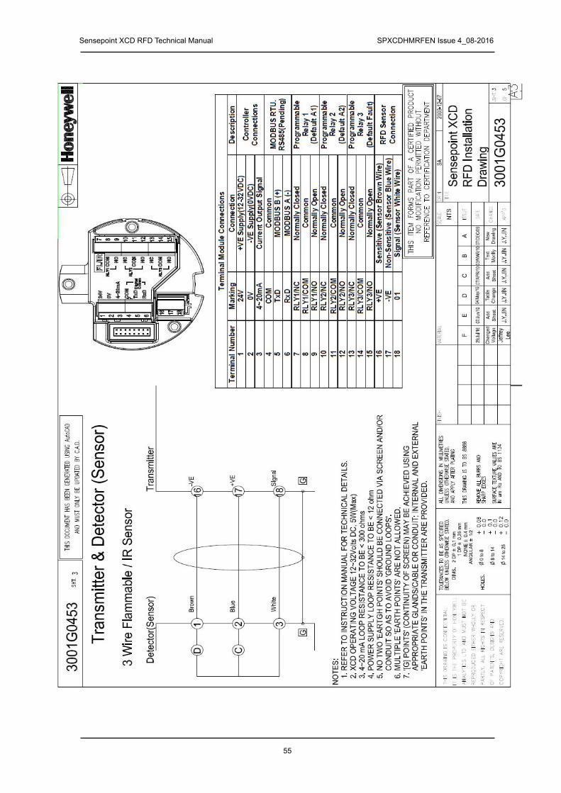
Sensepoint XCD RFD Technical Manual SPXCDHMRFEN Issue 4_08-2016
55
Term
inal
Mo
du
le C
on
nec
tio
ns
Term
inal
Nu
mb
er
Ma
rkin
g
Co
nn
ecti
on
D
es
cri
pti
on
1
24V
+
VE
Su
pp
ly(1
8-3
2V
DC
)
2
0V
-V
E S
up
ply
(0V
DC
)
3
4~
20
mA
C
urr
en
t O
utp
ut
Sig
nal
Co
ntr
oll
er
Co
nn
ec
tio
ns
4
CO
M
Co
mm
on
5
TxD
M
OD
BU
S B
(+
)
6
Rx
D
MO
DB
US
A (
-)
MO
DB
US
RT
U.
RS
48
5(P
en
din
g)
7
RL
Y1
/NC
N
orm
all
y C
los
ed
8
RL
Y1
/CO
M
Co
mm
on
9
RL
Y1
/NO
N
orm
all
y O
pe
n
Pro
gra
mm
ab
le
Re
lay 1
(D
efa
ult
A1
)
10
R
LY
2/N
C
No
rma
lly C
los
ed
11
R
LY
2/C
OM
C
om
mo
n
12
R
LY
2/N
O
No
rmall
y O
pe
n
Pro
gra
mm
ab
le
Re
lay 2
(D
efa
ult
A2
)
13
R
LY
3/N
C
No
rma
lly C
los
ed
14
R
LY
3/C
OM
C
om
mo
n
15
R
LY
3/N
O
No
rmall
y O
pe
n
Pro
gra
mm
ab
le
Re
lay 3
(D
efa
ult
Fa
ult
)
16
+
VE
S
en
sit
ive
(S
en
so
r B
row
n W
ire
)
17
-V
E
No
n-S
en
sit
ive
(S
en
so
r B
lue W
ire)
18
01
S
ign
al
(Sen
so
r W
hit
e W
ire
)
RF
D S
en
so
r C
on
nec
tio
n
NT
S
SA
07-D
ec-0
9
Sense
poin
t X
CD
R
FD
Insta
llation
Dra
win
g
30
01
G0
453
A
07/D
EC
/09
Ne
wD
raw
ing
J.Y
.JIN
03/
MA
R/1
0
B
Te
xt
Mo
dify
J.Y
.JIN
C
07/A
PR
/10
Ad
d S
he
et
J.Y
.JIN
J.Y
.JIN
04
/Ma
y/1
0
D
Ta
ble
Ch
an
ge
E
07/
Jun
/10
Ad
d S
he
et
J.Y
.JIN
300
1G
045
3
3 W
ire F
lam
mable
/ IR
Sensor
Bro
wn
-VE
+V
E
Sig
na
l
Tra
nsm
itte
r
1 2
Dete
cto
r(S
enso
r)
16
17
18
GG
3
Blu
e
Wh
ite
D C
Tra
nsm
itte
r &
Dete
cto
r (S
ensor)
NO
TE
S:
1
. R
EF
ER
TO
IN
ST
RU
CT
ION
MA
NU
AL
FO
R T
EC
HN
ICA
L D
ET
AIL
S.
2.
XC
D OPER
AT
ING
VOLTA
GE 1
2~32Vo
lts D
C, 5W(Ma
x)
3.
4~
20
mA
LO
OP
RE
SIS
TA
NC
E T
O B
E <
30
0 o
hm
s
4.
PO
WE
R S
UP
PL
Y L
OO
P R
ES
IST
AN
CE
TO
BE
< 1
2 o
hm
5
. N
O T
WO
'EA
RT
GH
PO
INT
S' S
HO
UL
D B
E C
ON
NE
CT
ED
VIA
SC
RE
EN
AN
D/O
R
CO
ND
UIT
SO
AS
TO
AV
OID
'GR
OU
ND
LO
OP
S'.
6
. M
UL
TIP
LE
'EA
RT
H P
OIN
TS
' AR
E N
OT
AL
LO
WE
D.
7
. '[G
] P
OIN
TS
' (C
ON
TIN
UIT
Y O
F S
CR
EE
N)
MA
Y B
E A
CH
IEV
ED
US
ING
A
PP
RO
PR
IAT
E G
LA
ND
S/C
AB
LE
OR
CO
ND
UIT
; IN
TE
RN
AL
AN
D E
XT
ER
NA
L
'EA
RT
H P
OIN
TS
' IN
TH
E T
RA
NS
MIT
TE
R A
RE
PR
OV
IDE
D.

Sensepoint XCD RFD Technical Manual SPXCDHMRFEN Issue 4_08-2016
56
17.3 Duct Mounting Drawing
NT
S
BE
N
6/
25/2
008
A
B
C
D
E
F
Du
ct
Mou
ntin
g H
ole
I. I
TE
M L
IST
1
. D
UC
T M
OU
NT
ING
PLA
TE
1
159 [6.279]150
[5.9
06
]
12
0 [4
.724]
1
0 [0.3
94]
4-
Mo
untin
g H
ole
10
0 [
3.9
37
]
164
[6
.45
7]
37 [1
.472]
12 [0.453]
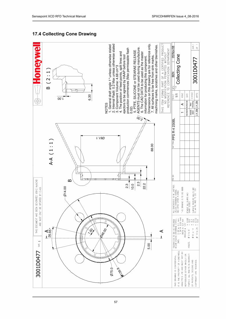
Sensepoint XCD RFD Technical Manual SPXCDHMRFEN Issue 4_08-2016
57
1/1
BE
NP
PS
R-4
230
BL
05
/Nov
/08
A
1
14.0
0
26.6
5°
1.00
1.60
48.
00
75
.0
138.
8
10
.0 2.3
22
.2
88.0
0
2.30
2.3
6.3
0
NO
TE
S 1
. G
en
era
l dra
ft a
ngle
1°
unle
ss o
therw
ise s
tate
d 2
. In
tern
al R
adii:
0.2
Max u
nle
ss o
the
rwis
e s
tate
d 3
. C
om
po
ne
nt V
olu
me: 4.6
8 c
m^3
4.
Th
e p
ositio
n o
f fe
ed
po
ints
, sp
lit lin
es a
nd
e
jecto
rs to
be a
gre
ed
by H
AA
P b
efo
re too
l p
rodu
ction c
om
me
nces (
Max p
erm
issa
ble
fla
sh
0
.02)
5.
PT
FE
, S
ILIC
ON
E o
r S
TE
AR
AE
RE
LE
AS
E
AG
EN
TS
must n
ot be
used
durin
g m
an
ufa
ctu
re.
6.
Th
e C
AD
DA
TA
to b
e u
sed a
s the m
aste
r in
form
ation
fo
r p
roducin
g th
is c
om
pone
nt.
Dim
ensio
ns o
n th
is d
raw
ing a
re fo
r re
fere
nce o
nly
. 7
. A
ll surf
ace
s t
o b
e f
ree fro
m s
ink m
ark
s,
ma
ch
inin
g m
ark
s,
scra
tche
s a
nd
oth
er
ble
mis
hes.
5.0
0
61.1 Ø
17.4 Collecting Cone Drawing

Sensepoint XCD RFD Technical Manual SPXCDHMRFEN Issue 4_08-2016
58
2/1
BE
N31
6S
S
25/O
ct/0
7
A
B
C
D
1
5.3
0
8.0 Ø
13
120
M8
x1.2
5 -
6g
8
13
M8x1.2
5 -
6H
31
2
14
.96
8.3
6
1.9
8
17.5 Mounting Bolt Assy Drawing

Sensepoint XCD RFD Technical Manual SPXCDHMRFEN Issue 4_08-2016
59
17.6 Mounting Bracket Drawing

Sensepoint XCD RFD Technical Manual SPXCDHMRFEN Issue 4_08-2016
60
17.7 Sensepoint XCD RFD Sensor

Sensepoint XCD RFD Technical Manual SPXCDHMRFEN Issue 4_08-2016
61
DIMS
.
2 D
P 0
.1 m
mBE
LOW
UNLE
SS O
THER
WISE
STA
TED.
TOLE
RANC
ES T
O BE
AS
SPEC
IFIE
D
ANGU
LAR
1/2 ~
n 14
to
25
n 8
to 1
4
n 0
to 8
HOLE
S.
SURF
ACE
TEXT
URE
VALU
ES A
REIN
um
Ra A
ND T
O BS
113
4
REMO
VE A
LL B
URRS
AND
AND
APPL
Y AF
TER
PLAT
ING
THIS
DRA
WING
IS
TO B
S 88
88
UNLE
SS O
THER
WISE
STA
TED.
ALL
DIME
NSIO
NS I
N MI
LLIM
ETRE
S
+ 0.1
+ 0.12
- 0.0
- 0.0
+ 0.08
- 0.0
NONE
0.4
mm
1 DP
0
.25
mm
SHAR
P ED
GES
SHT.
THIS
DOC
UMEN
T HA
S BE
EN G
ENER
ATED
USI
NG A
utoC
AD
AND
MUST
ONL
Y BE
UPD
ATED
BY
C.A.
D.
THIS
DRAWING
ISCONFIDENTIAL.
ITIS
THE
PROPERTY
OF
HONEYWELL
ANALY
TICS
LTD
AND
MUST
NOT
BE
REPRODUCED
EITHER
WHOLLY
OR
PARTLY
.ALL
RIGHTS
INRESPECT
OF
PATENTS,DESIGNS
AND
COPYRIGHT
ARE
RESERVED.
A3
THIS ITEM FORMS PART OF A CERTIFIED PRODUCT
NO MODIFICATION PERMITTED WITHOUT
REFERENCE TO CERTIFICATION DEPARTMENT
APP'D
CHANGE
DATE
ISSUE
SCALE
NTS
MATERIAL
FINISH
Ben
2011
-08-
25
Sen
sepo
intX
CD
RFD
Con
trol
Dra
win
gfo
rcC
SAus
3001
EC09
1.SHT.
.OF
1 2
DR'N
TITLE
125
/AUG
/11
New
Dra
win
gJe
ffrey L
16/A
UG
/12
2
Not
esch
ange
dJe
ffrey
L.
305
/SEP
/12
Not
esch
ange
dJe
ffrey
L.
3001
EC09
11
XCD
Tran
smitt
erw
ithR
emot
eSe
nsep
oint
Sens
or(D
irect
Mou
nt)
Mod
el70
5-A-
1733
Sen
sor
18"
MA
X
Seal
Fitti
ng
Cla
ssI,
Div
isio
n1,
Gro
upB
,C&
DH
azar
dous
Loca
tions
inac
cord
ance
with
CEC
and
NEC
rule
s.O
rdin
ary
Loca
tion
Sens
epoi
ntSe
nsor
with
outL
ocal
Tran
smitt
er
Cla
ssI,
Div
isio
n1,
Gro
upB,
C&
DH
azar
dous
Loca
tions
inac
cord
ance
with
CE
Can
dN
ECru
les.
Ord
inar
yLo
catio
n Junc
tion
Box
suita
ble
fort
helo
catio
nM
odel
2430
-002
1Ju
nctio
nB
ox
Mod
el70
5-A
-173
3Se
nsor
Figu
re1
Figu
re2
Seal
requ
irem
ents
aspe
rins
truct
ions
onju
nctio
nbo
x
17.8 Control Drawing

Sensepoint XCD RFD Technical Manual SPXCDHMRFEN Issue 4_08-2016
62
DIM
S.
2
DP
`
0.1
mm
BELO
W UN
LESS
OTH
ERWI
SE S
TATE
D.TO
LERA
NCES
TO
BE A
S SP
ECIF
IED
ANGU
LAR
` 1/2 ~
n 1
4 t
o 2
5
n 8
to
14
n 0
to
8HO
LES.
SURF
ACE
TEXT
URE
VALU
ES A
REIN
um
Ra A
ND T
O BS
113
4
REMO
VE A
LL B
URRS
AND
AND
APPL
Y AF
TER
PLAT
ING
THIS
DR
AWIN
G IS
TO
BS
8888
UNLE
SS O
THER
WISE
STA
TED.
ALL
DIM
ENSI
ONS
IN M
ILLI
MET
RES
+ 0.1
+ 0.12
- 0.0
- 0.0
+ 0.08
- 0.0
NONE
` 0.
4 mm
1 DP
`
0.25
mm
SHAR
P ED
GES
SHT.
THIS
DOC
UMEN
T HA
S BE
EN G
ENER
ATED
USI
NG A
utoC
AD
AND
MUS
T O
NLY
BE U
PDAT
ED B
Y C.
A.D.
TH
ISD
RA
WIN
GIS
CO
NF
IDE
NT
IAL.
ITIS
TH
EP
RO
PE
RT
YO
FH
ON
EY
WE
LL
AN
ALY
TIC
SLT
DA
ND
MU
ST
NO
TB
E
RE
PR
OD
UC
ED
EIT
HE
RW
HO
LLY
OR
PA
RT
LY.
ALL
RIG
HT
SIN
RE
SP
EC
T
OF
PA
TE
NT
S,
DE
SIG
NS
AN
D
CO
PY
RIG
HT
AR
ER
ES
ER
VE
D.
A3
THIS
IT
EM
FO
RM
S
PAR
T O
F A
CE
RTI
FIE
D
PR
OD
UC
TN
O
MO
DIF
ICAT
ION
P
ER
MIT
TED
W
ITH
OU
TR
EFE
RE
NC
E
TO
CE
RTI
FIC
ATIO
N
DE
PAR
TME
NT
APP'
D
CH
ANGE
DATE
ISSU
E
SCAL
E
NTS
MAT
ERIA
LFI
NIS
HBe
n
20
11-0
8-25
Sen
sepo
int X
CD
R
FD C
ontro
l D
raw
ing
for c
CSA
us30
01EC
091
.SHT
.
.OF
2 2
DR'N
TITL
E
125
/AUG
/11
New
Dra
win
gJe
ffrey L
16/A
UG
/12
2
Not
esch
ange
dJe
ffrey
L.
305
/SEP
/12
Not
esch
ange
dJe
ffrey L.
3001
EC09
12 XC
D T
rans
mitt
er a
nd S
ense
poin
t Sen
sor R
emot
ed.
Mod
el70
5-A
-173
3 Se
nsor
Junc
tion
Box
suita
ble
for t
he lo
catio
nM
odel
243
0-00
21 J
unct
ion
Box
Seal
ing
Fitti
ng
18"MAX
18"
MAXX
CD
Tran
smitt
er
Sea
ling
Fitti
ng
Cla
ssI,
Div
isio
n1,
Gro
upB,
C&
DH
azar
dous
Loca
tions
inac
cord
ance
with
CEC
and
NE
Cru
les.
Ord
inar
yLo
catio
n
Figu
re 3
Seal
requ
irem
ents
as p
er in
stru
ctio
nson
junc
tion
box

Sensepoint XCD RFD Technical Manual SPXCDHMRFEN Issue 4_08-2016
63
18 Certification18.1 China GB Ex and PA
China GB Ex (Chinese Version):

Sensepoint XCD RFD Technical Manual SPXCDHMRFEN Issue 4_08-2016
64
China GB Ex (English Version):

Sensepoint XCD RFD Technical Manual SPXCDHMRFEN Issue 4_08-2016
65
China PA Certification:
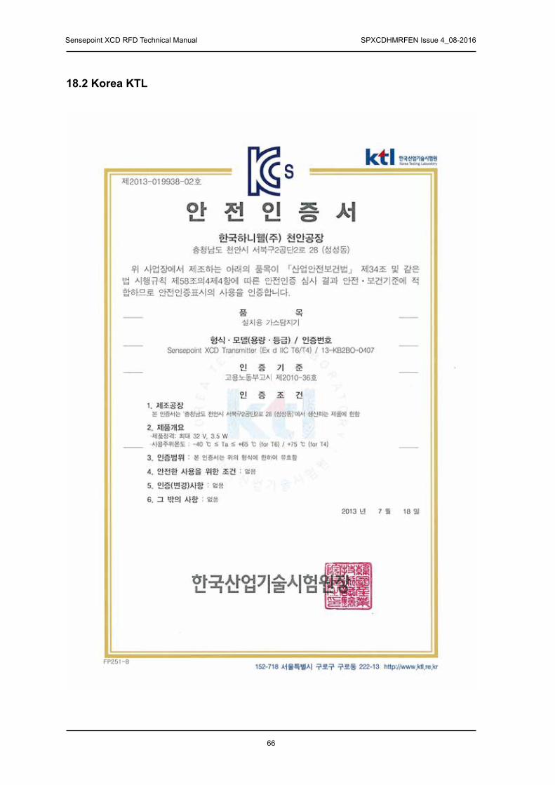
Sensepoint XCD RFD Technical Manual SPXCDHMRFEN Issue 4_08-2016
66
18.2 Korea KTL

Sensepoint XCD RFD Technical Manual SPXCDHMRFEN Issue 4_08-2016
67
18.3 European ATEXATEX For Transmitter:

Sensepoint XCD RFD Technical Manual SPXCDHMRFEN Issue 4_08-2016
68
ATEX for Sensor

Sensepoint XCD RFD Technical Manual SPXCDHMRFEN Issue 4_08-2016
69
18.4 International IECIEC Ex for Transmitter
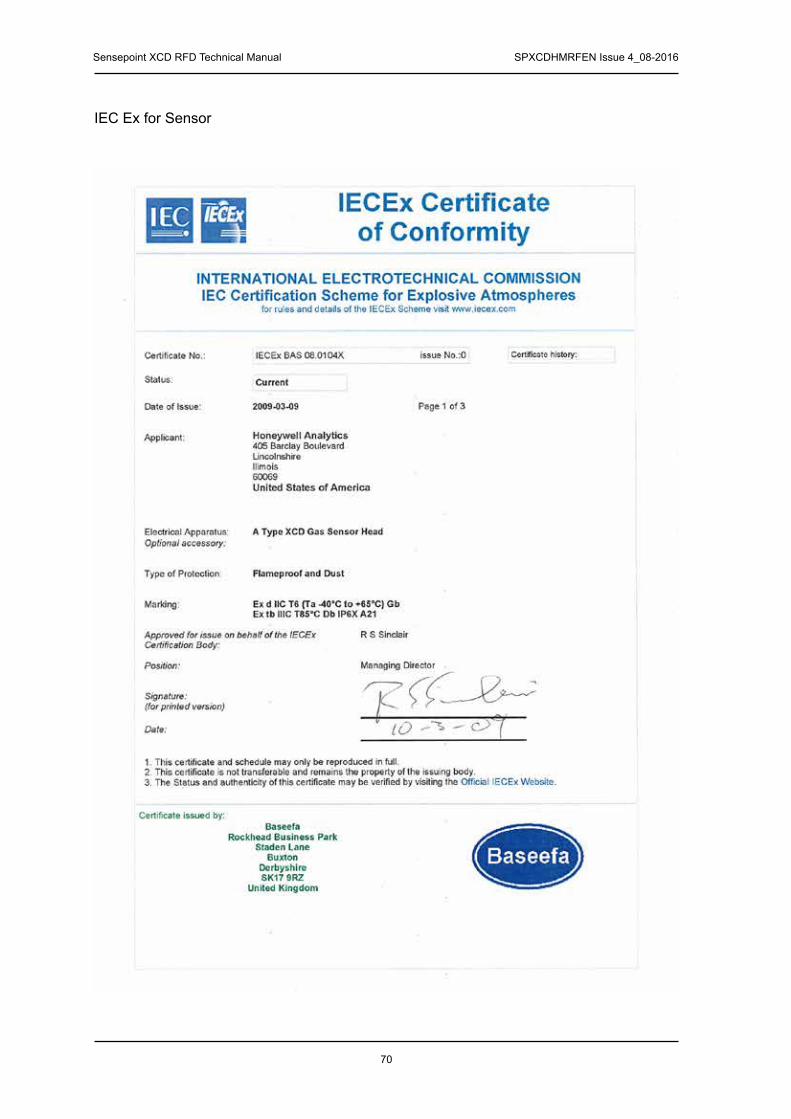
Sensepoint XCD RFD Technical Manual SPXCDHMRFEN Issue 4_08-2016
70
IEC Ex for Sensor

Sensepoint XCD RFD Technical Manual SPXCDHMRFEN Issue 4_08-2016
71
18.5 Sensepoint XCD RFD cCSAus Name Plate
Sens
epoin
t XCD
AT
EX N
ame
Plat
e
NONE
JIS
G43
04: S
US 3
16M
inim
um T
hickn
ess:
0.5m
m
ADD
Certi
.M
EDNO
TES
1. T
his
is a
n A
TEX
sch
edul
e dr
awin
g an
d ca
n on
ly
be
cha
nged
afte
r app
rova
l is
give
n by
the
certi
fiyin
g bo
dy
2. P
rodu
ct n
ame
form
at:
Hon
eyw
ell S
ense
poin
t XC
D X
XX
XX
X
Bla
nk -
Sen
sepo
int X
CD
for u
se w
ith S
ense
poin
t
XC
D s
ocke
t and
sen
sor.
R
TD -
Sen
sepo
int X
CD
RTD
for u
se w
ith m
A
inp
ut s
enso
rs s
uch
as S
ense
poin
t Tox
ic.
R
FD -
Sen
sepo
int X
CD
RFD
for u
se w
ith m
V
inp
ut s
enso
rs s
uch
as S
ense
poin
t Fla
mm
able
3. S
eria
l no.
form
at
S
/N: S
IIPP
PY
YW
WN
NN
S
eque
nce
num
ber
Wee
k of
MFG
Yea
r of M
FG
P
art C
ode
Issu
e S
tate
S
UP
PLI
ER
CO
DE
4. E
tchi
ng D
epth
: 0.
1 m
m
THIS
DOC
UMEN
T HAS
BEE
N GE
NERA
TED
USDI
NG
ADOB
E ILL
USTR
ATOR
AND
MUS
T ON
LY B
E UP
DATE
D BY
A.I.
3001
EA
041
3001
EA
041
BEN
HUR
16
MAY
08
NONE
THIS
DR
AWIN
G IS
CO
NFID
EN-
TIAL
. IT
IS
THE
PROP
ERTY
OF
HONE
YWEL
L AN
ALYT
ICS
LTD
AND
MUS
T NO
T BE
RE
PRO-
DUCE
D EI
THER
W
HOOL
Y OR
PA
RTLY
. ALL
RIG
HTS
IN R
ESPE
CT
OF
PATE
NTS,
DE
SIGN
S AN
D CO
PYRI
GHT A
RE R
ESER
VED.
APPR
OVED
BY
CHAN
GE
DATE
ISSU
E
SCAL
EM
ATER
IAL
FINI
SHTI
TILE
DRAW
ING
SHT.
OF
THIS
ITEM
FOR
MS
PART
OF
A CE
RTIF
IED
PROD
UCT
NO M
ODIF
ICAT
ION
PERM
ITTE
D W
ITHO
UTRE
FERE
NCE
TO C
ERTI
FICA
TION
DEP
ARTM
ENT
SHT.
130
/SEP
/08
ADD
Certi
. IP
66 J.Y.JI
N
218
/NOV
/09
ADD
NOTE
S
J.Y.JI
N
301
/JUL/
10
J.Y.JI
N
A
DDCe
rti. N
o.
412
/DEC
/11
Jeffr
ey L
.
CHAN
GED
T
amb.5
24/A
PR/1
2
Jeffr
ey L
.
603
/MAY
/12
Adjus
ted
Desc
riptio
n
Jeffr
ey L
.
703
/SEP
/12
Add
Coun
tryof
Orig
in
Jeffr
ey L
.
805
/OCT
/12
Add
“Ref
erTo
Man
ual”
Jeffr
ey L
.
905
/SEP
/13
Chan
ge
Pmax
to 5
.5
Jeffr
ey L
.
1010
/SEP
/13
Chan
ge
Cert.
Mar
k
Jeffr
ey L
.
13-K
B2BO
-040
7
Hon
eyw
ell S
ense
poin
t XC
DH
oney
wel
l Ana
lyti
cs In
c. L
inco
lnsh
ire,
IL, U
SA
600
69
WH
EN
EN
ER
GIS
ED
OR
WH
EN
AN
EX
PLO
SIV
E
ATM
OS
PH
ER
E IS
PR
ES
EN
T
: DO
NO
T O
PE
N7F
San
gAm
IT T
ower
,43
4 W
orld
cup
Buk
-ro,
Map
o-gu
,S
eoul
039
22, K
orea
Inst
alla
tion
Dra
win
g N
o.30
01G
0471
. Tem
p. C
ode
T4 3
2Vol
ts
Rea
d S
ense
poin
t XC
D M
anua
l prio
r to
use
and
inst
all a
s pe
r
DC
MA
X. C
lass
2, P
max
=5.5
W II 2
GD
Ex
d IIC
Gb
T6(T
a -4
0 to
+65
)
T5(
Ta -
40
to +
75
)E
x tb
IIIC
Db
T85(
Ta -
40
to +
65
) IP
66
T10
0(T
a -4
0 to
+75
)
0344
WA
RN
ING
S/N
: P
/N :
EN
455
44 (
Toxi
c)
E
N 6
0079
-29-
1(Fl
amm
able
)E
N 5
0104
(O
xyge
n)
Mad
e in
Kor
ea
Ref
er T
o M
anua
l
Bas
eefa
08A
TEX
0222
IE
CE
x B
AS
08.
0072

Sensepoint XCD RFD Technical Manual SPXCDHMRFEN Issue 4_08-2016
72
18.6 Sensor Cartridges Label
N
P/N
: Se
nsep
oint
XC
D
Dis
posa
ble
Sens
or
WA
RN
ING
: D
O N
OT
SEPA
RA
TE
WH
EN E
NER
GIS
EDS/
N :
SIIP
PPYY
WW
NN
NN
Rev
.
Hon
eyw
ell A
naly
tics
Inc.
Li
ncol
nshi
re, I
L, U
SA 6
0069
II 2
GD
Ex d
IIC
T6(
Ta -4
0to
+65
) Gb
Ex tb
IIIC
T85
Db
IP66
A21
Bas
eefa
08A
TEX0
316X
IEC
Ex B
AS
08.0
104X
Gas
Typ
e
Rev
isio
n N
umbe
r
THIS
DOC
UMEN
T HAS
BEE
N GE
NERA
TED
USDI
NG
ADOB
E ILL
USTR
ATOR
AND
MUS
T ON
LY B
E UP
DATE
D BY
A.I.
3001
EA
053
3001
EA
053
Sens
or C
artr
idge
Lab
el
Art
wor
k D
raw
ing
BEN
HUR
12
SEP
08
NTS
A12
/SEP
/08
NEW
DRAW
ING
J.Y.JI
N
THIS
DR
AWIN
G IS
CO
NFID
EN-
TIAL
. IT
IS
THE
PROP
ERTY
OF
HONE
YWEL
L AN
ALYT
ICS
LTD
AND
MUS
T NO
T BE
RE
PRO-
DUCE
D EI
THER
W
HOOL
Y OR
PA
RTLY
. ALL
RIG
HTS
IN R
ESPE
CT
OF
PATE
NTS,
DE
SIGN
S AN
D CO
PYRI
GHT A
RE R
ESER
VED.
APPR
OVED
BY
CHAN
GE
DATE
ISSU
E
SCAL
EM
ATER
IAL
FINI
SHTI
TILE
DRAW
ING
SHT.
OF
THIS
ITEM
FOR
MS
PART
OF
A CE
RTIF
IED
PROD
UCT
NO M
ODIF
ICAT
ION
PERM
ITTE
D W
ITHO
UTRE
FERE
NCE
TO C
ERTI
FICA
TION
DEP
ARTM
ENT
SHT.
110
/NOV
/08
J.Y.JI
N
REVI
SED
0344
Max
. Rat
ing:
4.0
V, 2
50m
A, 1
W
204
/MAR
/09
J.Y.JI
N
ADD
NOTE
Mat
t met
alliz
ed P
ET 5
0um
Adhe
sive
: Acr
ylic
NO
TE1.
LEG
END
TO
BE
THER
MA
LLY
TR
AN
SFER
PR
INTE
D IN
BLA
CK
ON
TO B
LAN
K L
AB
EL.
302
/APR
/09
J.Y.JI
N
Chan
geIP
Gra
de

Sensepoint XCD RFD Technical Manual SPXCDHMRFEN Issue 4_08-2016
73
19 Cross Interference and Cross Calibration19.1 Cross Calibration Flammable Gas Detector
For greater accuracy, a catalytic gas detector should be calibrated using a certifiedgas/air mixture equal to 50% LEL of the actual target gas intended to be monitored.
However, it is not always practical to obtain every detectable type of hydrocarbon gas in a calibration-ready, certified and verifiable form. Therefore, it is possible to carry out a “cross calibration” using another hydrocarbon gas/air mixture.
When the Sensepoint XCD Combustible LEL sensor is to be calibrated with a gas which is different to the gas or vapour to be detected, the following cross calibration procedure may be followed:
Notes:1. Table 14 lists a selection of hydrocarbon compounds and states a reference figure or “Star Rating” according to the reaction they produce in relation to other hydrocarbons.2. An eight star (8*) gas produces the highest output, while a one star (1*) gas produces the lowest output.
No. Gas Star Rating1 Acetone 4*2 Ammonia 7*3 Benzene 3*4 Butanone 3*5 Butane 4*6 Butyl acetate 1*7 Butyl acrylate 1*8 Cyclohexane 3*9 Cyclohexanone <1*10 Diethyl ether 4*11 Ethane 6*12 Ethanol 5*13 Ethyl acetate 3*14 Ethylene 5*15 Heptane 3*16 Hexane 3*17 Hydrogen 6*18 Methane 6*19 Methanol 5*20 MIBK 3*21 Octane 3*
Caution: Where the user calibrates any sensor using a different gas, responsibility for identifying and recording calibration rests with the user. Refer to the local regulations where
appropriate.

Sensepoint XCD RFD Technical Manual SPXCDHMRFEN Issue 4_08-2016
74
22 Pentane 3*23 Propane 5*24 Propan-2-ol 4*25 Styrene 2*26 Tetra hydrafuran 4*27 Toluene 3*28 Triethylamine 3*29 Xylene 2*
Table 14 . Star Rating of Gases
To cross calibrate the Sensepoint XCD flammable gas detector:(1) Obtain the star rating for both the calibration test gas and the gas to be detected from Table 14(2) These values may then be used in Table 15 to obtain the required calibration span setting when a 50% LEL test gas is applied to the detector.
*Rating of *Rating of Gas to be Detected Calibration Gas 8* 7* 6* 5* 4* 3* 2* 1* 8* 50 62 76 95 - - - - 7* 40 50 61 76 - - - - 6* 33 41 50 62 78 - - - 5* 26 33 40 50 63 79 - - 4* - 26 32 40 50 63 80 - 3* - - 26 32 40 50 64 81 2* - - - 25 31 39 50 64 1* - - - - 25 31 39 50Note: These settings must only be used with a calibration gas concentration of 50% LEL.
Table 15. Calibration span setting
(3) If a sensor is to be used to detect a gas other than that for which it was calibrated and there is no intention to use an equivalent calibration gas to re-calibrate the sensor, then the required correction factor may be obtained from Table 16.
The reading shown on the gas detector controller or transmitter display should bemultiplied by this number in order to obtain a more accurate gas concentration result.
Sensor calibrated to Sensor used to detect detect 8* 7* 6* 5* 4* 3* 2* 1* 8* 1.00 1.24 1.52 1.89 2.37 2.98 3.78 4.83 7* 0.81 1.00 1.23 1.53 1.92 2.40 3.05 3.90 6* 0.66 0.81 1.00 1.24 1.56 1.96 2.49 3.17 5* 0.53 0.66 0.80 1.00 1.25 1.58 2.00 2.55 4* 0.42 0.52 0.54 0.80 1.00 1.26 1.60 2.03 3* 0.34 0.42 0.51 0.64 0.80 1.00 1.27 1.62 2* 0.26 0.33 0.40 0.50 0.63 0.79 1.00 1.28 1* 0.21 0.26 0.32 0.39 0.49 0.62 0.78 1.00
Table 16. Correction factors

Sensepoint XCD RFD Technical Manual SPXCDHMRFEN Issue 4_08-2016
75
Notes:1. Since catalytic sensors require oxygen for correct operation, a mixture of gas in airshould always be used for calibration purposes.2. Assuming average performance of the sensor, the sensitivity information in Tables 14 To 16 is normally accurate to + or - 30%.
Working Example:If the target gas to be detected is 0-100%LEL Ethylene and the only calibration gasavailable to re-calibrate the sensor is Methane (at 50% LEL concentration), the procedure is as follows:(1) Look up the star rating for each gas in Table 14:
Gas No. 14, Ethylene = 5* Gas no. 18, Methane = 6*
(2) Then, look up the span settings for a 50% LEL calibration gas in Table 15 by selecting the row of figures next to the 6* in the “calibration gas” column. Select the figure in the 5* column of the “gas to be detected” section. The figure is 62.
(3) This means that during re-calibration, the span gas setting on the gas detectortransmitter or controller should be set to 62% LEL to give an accurate measuring scale for 0-100%LEL Ethylene, when using 50% LEL Methane as the calibration gas.
Section 19.1 is used for Sensepoint XCD Catalytic Sensor only, please refer to Sensepoint Technical Manual for using Sensepoint flammable gas sensors.
Please contact your local Honeywell Analytics sales or service distributor, or regional offce should further clarification or additional information be required.

Sensepoint XCD RFD Technical Manual SPXCDHMRFEN Issue 4_08-2016
76
19.2 Meter Multiplication Factors for Sensepoint XCD-IR Propane
It is possible to apply a linear cross reference factor to the output of a sensor characterized for propane and achieve the results shown in the graph below.Reasonable accuracy is maintained to at least the 50% LEL equivalent values of the cross-referred gasses.
XCD IR Propane Sensor (Full scale 2% Vol/100%LEL)
Diagram 18. Sensepoint XCD-IR (Propane) Sensor with linear cross-reference factor appliedfactor applied
Use the following multiplying factors to cross-refer to the propane reading:Gas Multiplication Factor
Ethylene 3.43nButane 0.97
nPentane 0.89Table 17. Multiplying Factors
NOTEHoneywell Analytics recommends that users verify the accuracy of their instruments using test gasses wherever possible. Cross-referred measurements should be used as a guide only, not as absolute values.
Caution: These factors only apply to gas concentrations expressed in % Volume terms.When using a linear cross reference factor the temperature compensation is
based upon propane, and there may be errors at temperatures away from the calibration temperature.

Sensepoint XCD RFD Technical Manual SPXCDHMRFEN Issue 4_08-2016
77
XCD Transmitter
Appendix A - Modbus® Protocol A-2
A.1 Modbus and the XCD
The XCD gas detector may be fitted with the optional Modbus board. Authoritative information on the MODBUS Upgrade Kit can be found at www.modbus.org. The XCD supports Modbus/RTU over an RS-485 physical layer. The interface is isolated and includes a switchable 120 Ohm termination resistor. Baud rates 9600 or 19,200 are supported with 19,200 as the default. Most of the operations that are possible with local user interfaces can also be performed using the Modbus interface. This includes configuration operations. However, this Appendix only describes how to monitor XCD status using Modbus.
See Section 4.1.1 for information on installing the optional Modbus hardware. See Section 4.1.1 Configure Menu – Set ID Settings for information on setting the Modbus baud rate and Parity using the local user interface.

Sensepoint XCD RFD Technical Manual SPXCDHMRFEN Issue 4_08-2016
78
A.2 Modbus Registers
ModBus RegisterAddress
Information R/W Type Size Note
30001 Main SW Version of XCD R u8 130002 EEP Version of XCD R u8 130003 WatchDog s/w Version of XCD R u8 130004 Location string R string[12] 630010 ModBus slave ID R u8 1
30011 Monitor Status R u16 1 Upper byte : FunctionLower byte : Instrument Mode
30012 Inhibit current(mA) R u8 1 20 means 2.0mA30013 Reserved R u16 1
30014 Active Alarm R u32 2 bit 0 Alarm 1 is activebit 1 Alarm 2 is active
30016 Latched Alarm R u32 2 bit 0 Alarm 1 is activebit 1 Alarm 2 is active
30018 Active Fault R u32 2
Upper Byte: faultLower Byte:warning Bit 0:W1~Bit 6:W6 Bit 7:F1~Bit 11:F5
30020 Latched Fault R u32 2
Upper Byte: faultLower Byte:warning Bit 0:W1~Bit 6:W6 Bit 7:F1~Bit 11:F5
40001 Systern ID code R u16 1 Upper Byte : Type Code : 0x25Lower Byte : My Address
40002 Systern ID code R u16 1 Upper Byte : Type Code : 0x25Lower Byte : My Address : Dummy Spacer
40003 Gas reading R f32 2
40005 Fault and Warning R u8 1 Fault = 1100 + NumberWarning = Number as is
40006 Alarm, fault and warning state R u8 1
bit 0 Alarm 1 is activebit 1 Alarm 2 is activebit 2,3 for future expansionbit 4 Warning is activebit 5 Fault is activebit 6,7 for future expansionNote: Latching relay setting latches Modbus values in register 40006.
40007 Monitor state monitering R u8 1
1 : Normal2 : Warm Up after power on3 : Inhibit12 : Calibration
40008 Reserved R u16 140009 Ca libration Due R f32 2
40011 Measuring Unit R u8 1
4 : PPM3 : %Vol5 : %LEL1 : mg/m3
40012 Peak Reading R f32 2 Peak Reading40014 Reserved R u16 340017 Temperature (oC) R s16 140018 Reserved R u16 2840046 Measuring Gas name string R string[14] 740053 Reserved R s16 140054 Temperature (oF) R s16 140055 Reserved R u16 140056 Relay Status R u8 1 1 : Energized, 0 : De-energized40057 Power Supply R f32 240059 Calibration Interval R/W u16 1
40060 Alarm Type R/W u8 1High nibble : Alarm 2 TypeLow nibble : Alarm 1 Type 0: Disable, 1: Rising, 2:Falling
40061 Inhibit timeout R/w u16 1
40062 Relay configuration R/w u8 1Bit: 0 ~ 2: Relay Type1 ~ Relay Type3Bit: 3~5 : Relay Sstatus1 ~ Relay Status 3Bit: 6 : Relay Latch Status


3001M5023_4_ECO HAA160010SPXCDHMRFENMAN0894_EMEAI© 2016 Honeywell Analytics
Please Note:While every effort has been made to ensure accuracy in this publication, no responsibility can be accepted for errors or omissions. Data may change, as well as legislation, and you are strongly advised to obtain copies of the most recently issued regulations, standards, and guidelines. This publication is not intended to form the basis of a contract.
12723
Contact Honeywell Analytics:
Find out more
www.honeywellanalytics.com
Europe, Middle East, Africa, India
Life Safety Distribution AG
Javastrasse 2
8604 Hegnau
Switzerland
Tel: +41 (0)44 943 4300
Fax: +41 (0)44 943 4398
India Tel: +91 124 4752700
Americas
Honeywell Analytics Inc.
405 Barclay Blvd.
Lincolnshire, IL 60069
USA
Tel: +1 847 955 8200
Toll free: +1 800 538 0363 Fax: +1 847 955 [email protected]
www.honeywell.com
Technical Services
EMEAI: [email protected]
Asia PacificHoneywell Analytics Asia Pacific CO., Ltd7F SanAm IT Tower434 Worldcup Buk-ro, Mapo-guSeoul 03922Korea
Tel: +82 (0)2 6909 0300
Fax: +82 (0)2 2025 0328
Issue 4 08/2016