Embed Size (px)
Citation preview

Technical Handbook for Cogeneration facilities
v.1.2
September 2015
Technical Handbook for Cogeneration facilities
1
Table of Contents
1 INTRODUCTION ......................................................................................................................... 2
2 REQUIREMENTS FOR DESCRIPTION OF COGENERATION FACILITIES ................. 3
2.1 SINGLE LINE DIAGRAM ............................................................................................................... 3 2.2 MOTORS .................................................................................................................................... 10 2.3 MONITORING EQUIPMENT OF CHP FACILITIES ......................................................................... 10 2.4 ADDITIONAL EQUIPMENT .......................................................................................................... 11
3 METERING REQUIREMENTS IN COGENERATION FACILITIES ............................... 13
3.1 GENERAL REQUIREMENTS OF METERING DEVICES ................................................................... 13 3.1.1 Uncertainty (range error) and Systematic Error ............................................................ 14 3.1.2 Calibration and Validation of Meters ............................................................................. 15
3.2 MEASUREMENT OF FUEL ........................................................................................................... 17 3.2.1 Fuel categories ............................................................................................................... 17
Conventional Fuels................................................................................................................................... 17 Alternative fuels ....................................................................................................................................... 18 Imported Steam from an External Supplier (as Equivalent Fuel Consumption ) ...................................... 19 Recovered heat (as Equivalent Alternative Fuel Consumption ) .............................................................. 19
3.2.2 Measurement of Gas Fuels ............................................................................................. 20 3.2.3 Measurement of Liquid Fuels ......................................................................................... 21 3.2.4 Measurement of Solid Fuels ........................................................................................... 21 3.2.5 Measurement of Consumption of Alternative Fuels ........................................................ 21
Calorific Value of Alternative Fuel .......................................................................................................... 22 Determination of calorific value of Alternative Fuels .............................................................................. 23 Expressions of Calorific Value of Alternative Fuels and Conversions..................................................... 24 Determination of Energy Consumption of Alternative Fuels ................................................................... 27
3.2.6 Metering of Fuel Side-streams ........................................................................................ 28 3.2.7 Fuels with Variable Moisture Content ............................................................................ 28
3.3 MEASUREMENT OF THE ELECTRICITY PRODUCED .................................................................... 29 3.3.1 Mechanical Power Outputs ............................................................................................ 30 3.3.2 Meter location ................................................................................................................. 30 3.3.3 Meteriung Requirements ................................................................................................. 30
Electrical Power ....................................................................................................................................... 30 Mechanical Power .................................................................................................................................... 31
3.4 MEASUREMENT OF USEFUL HEAT PRODUCED .......................................................................... 32 3.4.1 Heat Transfer and Net Heat Exports from a Facility ..................................................... 33 3.4.2 Exhaust gases ................................................................................................................. 35 3.4.3 Hot Water ....................................................................................................................... 35 3.4.4 Steam .............................................................................................................................. 36 3.4.5 Direct Use of Heat .......................................................................................................... 37
4 STANDARDS .............................................................................................................................. 38
ANNEX I ............................................................................................................................................... 41
Technical Handbook for Cogeneration facilities
2
1 INTRODUCTION
This technical handbook aims to assist producers of electricity from
high efficiency Combined Heat and Power (CHP) facilities in issues
such as the description of their facilities as well as the monitoring of
fuels, electricity, heat, etc., that are used or produced by their
facilities.
These issues, namely the description of the installation and the
performance of measurements are required to properly complete the
application for registration of a facility for the Electronic Registry,
and the related application for Guarantee of Origin (presented in
Appendix I of this handbook) through the Electronic Registry, so
that the issuance of Guarantees of Origin (GO) CHP from the
Electronic Registry is possible.
The form of GOs for CHP is presented in Appendix II of this
handbook.
It is noted that the electricity which is taken into account for the
issuing of GOs for CHP is the nett electricity output to the grid, i.e.
the electricity output to the grid nett of any energy used by
production auxiliaries within the boundaries of the facility.
Technical Handbook for Cogeneration facilities
3
2 REQUIREMENTS FOR DESCRIPTION OF COGENERATION FACILITIES
2.1 SINGLE LINE DIAGRAM
A single-line diagram of the CHP installation is required, showing
the relationship of the CHP unit to the overall installation. The
diagram should include all the major components of the station
located within the CHP facility, their interconnections, and piping
and cables carrying fuel and energy to the CHP system, as well as
the generated electricity and thermal energy (steam, hot water or
exhaust gas, as appropriate). The fluid and the transported energy
should be clearly referred in all lines. In the case of steam and hot
water, the pressure and temperature should be included.
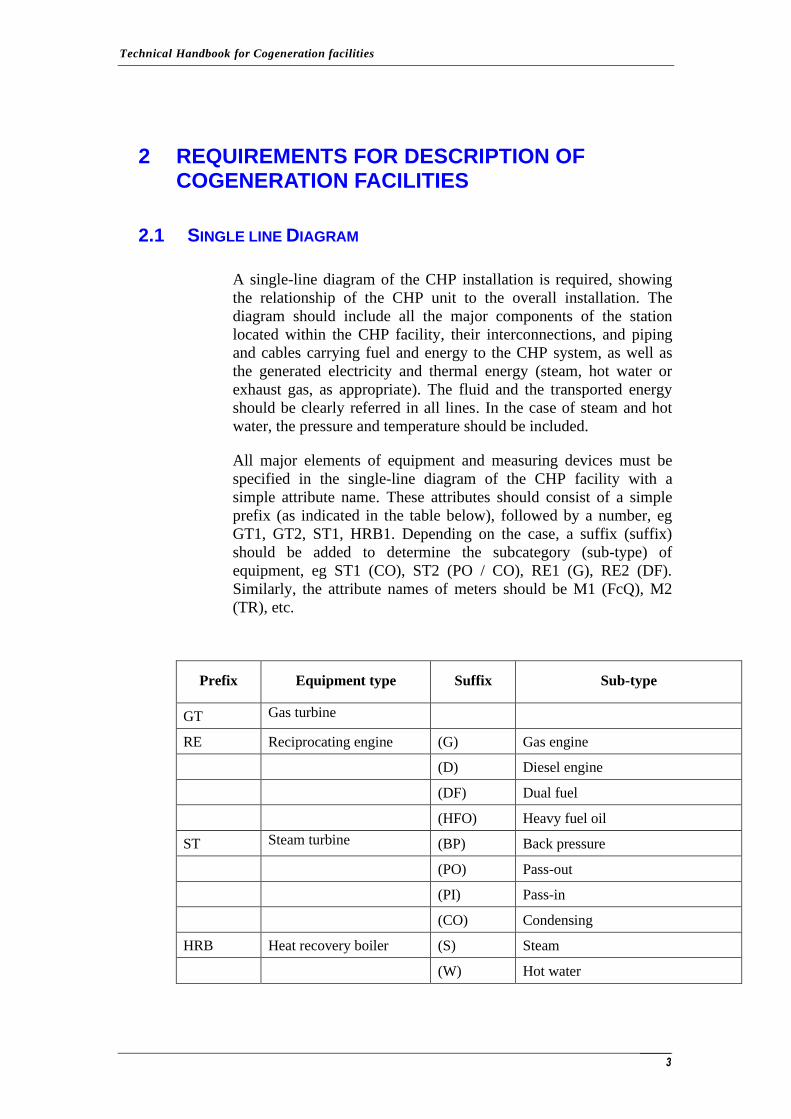
All major elements of equipment and measuring devices must be
specified in the single-line diagram of the CHP facility with a
simple attribute name. These attributes should consist of a simple
prefix (as indicated in the table below), followed by a number, eg
GT1, GT2, ST1, HRB1. Depending on the case, a suffix (suffix)
should be added to determine the subcategory (sub-type) of
equipment, eg ST1 (CO), ST2 (PO / CO), RE1 (G), RE2 (DF).
Similarly, the attribute names of meters should be M1 (FcQ), M2
(TR), etc.
Prefix Equipment type Suffix Sub-type
GT Gas turbine
RE Reciprocating engine (G) Gas engine
(D) Diesel engine
(DF) Dual fuel
(HFO) Heavy fuel oil
ST Steam turbine (BP) Back pressure
(PO) Pass-out
(PI) Pass-in
(CO) Condensing
HRB Heat recovery boiler (S) Steam
(W) Hot water
Technical Handbook for Cogeneration facilities
4
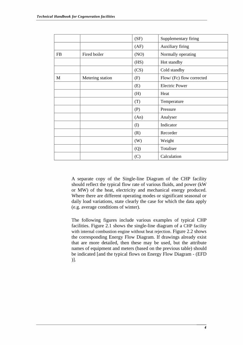
(SF) Supplementary firing
(AF) Auxiliary firing
FB Fired boiler (NO) Normally operating
(HS) Hot standby
(CS) Cold standby
M Metering station (F) Flow/ (Fc) flow corrected
(E) Electric Power
(H) Heat
(T) Temperature
(P) Pressure
(An) Analyser
(I) Indicator
(R) Recorder
(W) Weight
(Q) Totaliser
(C) Calculation
A separate copy of the Single-line Diagram of the CHP facility
should reflect the typical flow rate of various fluids, and power (kW
or MW) of the heat, electricity and mechanical energy produced.
Where there are different operating modes or significant seasonal or
daily load variations, state clearly the case for which the data apply
(e.g. average conditions of winter).
The following figures include various examples of typical CHP
facilities. Figure 2.1 shows the single-line diagram of a CHP facility
with internal combustion engine without heat rejection. Figure 2.2 shows
the corresponding Energy Flow Diagram. If drawings already exist
that are more detailed, then these may be used, but the attribute
names of equipment and meters (based on the previous table) should
be indicated [and the typical flows on Energy Flow Diagram - (EFD
)].

Technical Handbook for Cogeneration facilities
5
Figure 2.1: Line diagram of a CHP Facility with Internal Combustion Engine without Heat Rejection (with Oil or Natural gas or Βiogas as a fuel).
Figure 2.2: Energy flow diagram of a CHP Facility with Internal Combustion Engine without Heat Rejection (with Oil or Natural gas or Βiogas).
In the case that no heat rejection exists in the above CHP facility,
there is no measurement of the produced heat, because it can be
calculated from the produced electrical energy and the known
Technical Handbook for Cogeneration facilities
6
relationship between the electrical and thermal energy for this steam
engine.
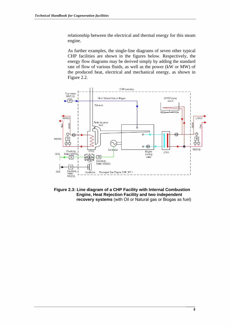
As further examples, the single-line diagrams of seven other typical
CHP facilities are shown in the figures below. Respectively, the
energy flow diagrams may be derived simply by adding the standard
rate of flow of various fluids, as well as the power (kW or MW) of
the produced heat, electrical and mechanical energy, as shown in
Figure 2.2.
Figure 2.3: Line diagram of a CHP Facility with Internal Combustion
Engine, Heat Rejection Facility and two independent recovery systems (with Oil or Natural gas or Βiogas as fuel)
Technical Handbook for Cogeneration facilities
7
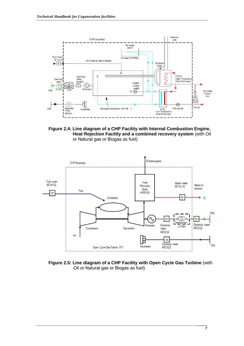
Figure 2.4: Line diagram of a CHP Facility with Internal Combustion Engine, Heat Rejection Facility and a combined recovery system (with Oil or Natural gas or Βiogas as fuel)
Figure 2.5: Line diagram of a CHP Facility with Open Cycle Gas Turbine (with Oil or Natural gas or Βiogas as fuel)
Technical Handbook for Cogeneration facilities
8
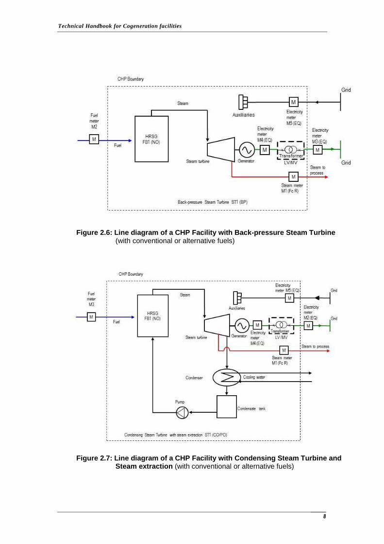
Figure 2.6: Line diagram of a CHP Facility with Back-pressure Steam Turbine (with conventional or alternative fuels)
Figure 2.7: Line diagram of a CHP Facility with Condensing Steam Turbine and Steam extraction (with conventional or alternative fuels)
Technical Handbook for Cogeneration facilities
9
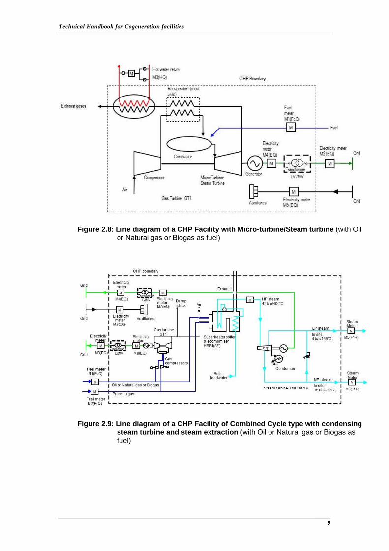
Figure 2.8: Line diagram of a CHP Facility with Micro-turbine/Steam turbine (with Oil or Natural gas or Βiogas as fuel)
Figure 2.9: Line diagram of a CHP Facility of Combined Cycle type with condensing steam turbine and steam extraction (with Oil or Natural gas or Βiogas as fuel)
Technical Handbook for Cogeneration facilities
10
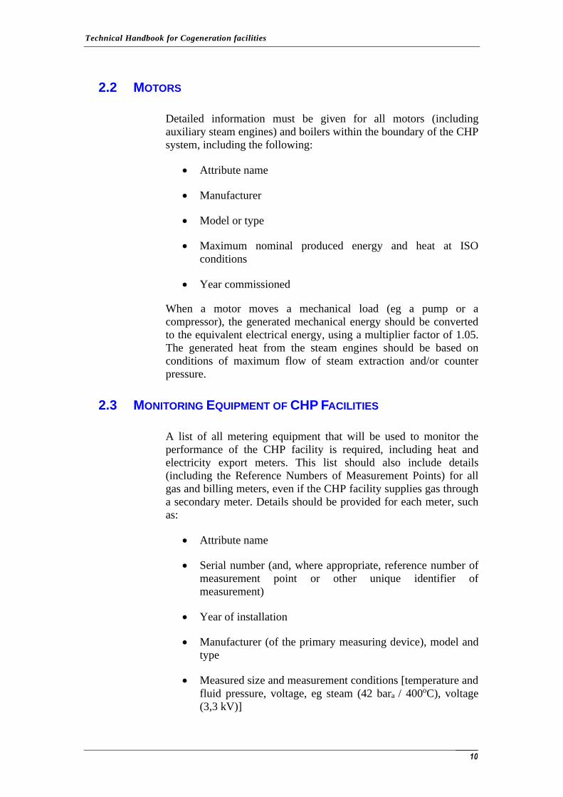
2.2 MOTORS
Detailed information must be given for all motors (including
auxiliary steam engines) and boilers within the boundary of the CHP
system, including the following:
• Attribute name
• Manufacturer
• Model or type
• Maximum nominal produced energy and heat at ISO
conditions
• Year commissioned
When a motor moves a mechanical load (eg a pump or a
compressor), the generated mechanical energy should be converted
to the equivalent electrical energy, using a multiplier factor of 1.05.
The generated heat from the steam engines should be based on
conditions of maximum flow of steam extraction and/or counter
pressure.
2.3 MONITORING EQUIPMENT OF CHP FACILITIES
A list of all metering equipment that will be used to monitor the
performance of the CHP facility is required, including heat and
electricity export meters. This list should also include details
(including the Reference Numbers of Measurement Points) for all
gas and billing meters, even if the CHP facility supplies gas through
a secondary meter. Details should be provided for each meter, such
as:
• Attribute name
• Serial number (and, where appropriate, reference number of
measurement point or other unique identifier of
measurement)
• Year of installation
• Manufacturer (of the primary measuring device), model and
type
• Measured size and measurement conditions [temperature and
fluid pressure, voltage, eg steam (42 bara / 400oC), voltage
(3,3 kV)]
Technical Handbook for Cogeneration facilities
11
• meter output range (excluding electricity meters that should
be indicated as N/A - not applicable), namely the minimum
and maximum flow rate (Qmin and Qmax for liquid flow
meters). The maximum reading of a totalizer is not indicated
(eg 999999)
• Meter output units (indicating if temperature and pressure
have been normalized)
• The percentage of uncertainty of reading or the percentage of
the measurement range. In this case only the uncertainty of
the basic meter/transmitter/computer is required, without
taking into account any additional uncertainty due to the
existence of excessive intervals between successive
calibrations (which may change every year)
In case the existing monitoring systems of a CHP facility do not
comply with the requirements specified in this report, applicants are
required to provide information concerning the additional
measurement systems that they propose to install and, where
appropriate, details of indirect methods to be used to calculate non-
measured quantities. The list of meters should also include details of
any metering equipment that is based on an indirect method of
calculating sizes.
In case of absence of measurement (or of inadequate measurement)
of the produced steam or heat, the non-measured heat should not be
included in the useful heat.
2.4 ADDITIONAL EQUIPMENT
Some additional elements of equipment, which are necessary for the
operation of a CHP facility, must also be specified. Such elements
of equipment include:
• Equipment to treat gaseous fuels such as gas compressors, or
sewage treatment equipment, gases from landfills or syngas.
• Equipment for processing or handling solid, fluid or gaseous
fuels. This might include pulverisers or shredders for coal or
solid waste; fuel storage for gas or for liquid fuels; filter
units, heaters to aid pumping and combustion of viscous
liquids, fuel pumps; pyrolysis or gasification equipment;
solid waste crainage and storage etc
Technical Handbook for Cogeneration facilities
12
• Start-up equipment, in order for the facility to be able to start
whether it is connected to the grid or not. This equipment
may include electric motors or batteries and diesel engines.
• Equipment for the transportation of electricity, including
direct connections.
• Equipment for additional or auxiliary combustion that is not
defined elsewhere, including air fans for auxiliary
combustion or for provision of additional and backup heat,
rack cooling etc.
• Equipment for treatment / management of water supply, of
the network of water or steam including degassing
equipment, deionization or softening equipment, water
filtration equipment, pumps, fans, etc.
• Equipment for treatment / management for direct use of gas
that is not identified elsewhere, such as dryers, etc.
• Other engines, pumps, fans, blowers, etc. required for the
operation of the facility.
• Other electrical parasitic equipment.
• Other mechanical parasitic equipment.
• Other heat parasitic equipment.
• Equipment for Continuous Emission Monitoring.
• Equipment for collection and disposal of ash and flue gas
treatment (FGT).
All the above equipment of the facility should be recorded with the
following details: manufacturer, model, number of elements, mode
of function (normal operation, operation at start-up or rarely
function), and an estimation of energy consumption (kWe or kWth).
In order to record the power demand (kW), the mechanical parasitic
loads should be treated as equivalent to electrical loads.
Technical Handbook for Cogeneration facilities
13
3 METERING REQUIREMENTS IN COGENERATION FACILITIES
3.1 GENERAL REQUIREMENTS OF METERING DEVICES
Good practice requires the achievement of an adequate level of
measurement, regarding the monitoring and improving of the
operation of a CHP facility.
The metering installation should be designed, manufactured and
installed according to the specifications of approved standards, such
as the Cypriot, European (EN), or International (ISO) Standards or
Guidelines.
In order to attain the measurements, the use of ‘smart' meters is
required, which should preserve the readings that were
recorded in the last 12 monthls at minimum. These meters
should also allow remote reporting in order to have the ability to
integrate in the system of collecting measurements of the Issuing
Authority. For compatibility reasons, the meters used should be
selected among those proposed by the Issuing Authority. In case
that the above requirements are unable to be met for practical
reasons, the applicant should prove it to the Issuing Authority
and with the agreement of the Issuing Authority the applicant
may use other types of meters.
When any commercial or fiscal transactions are carried out based on
readings of metered or measured quantities (eg fuel transfer with
supervision), such metering (the meter under which the billing
occurs) or the measured quantities should normally be regarded as
sufficient, since appropriate independent procedures for validation
have been implemented.
In all other cases (ie excluding of commercial or fiscal transactions)
of metering devices, the following requirements must be met:
• The appropriate validation procedures must be observed for
the monitoring system, either by direct calibration or by
validating each element of the measurement system.
• Periodic calibration must be performed by the manufacturer
or by accredited organizations.
Technical Handbook for Cogeneration facilities
14
• In order to ensure that the uncertainties of the monitoring
system are maintained within the specifications of the meter,
a program of calibration must be applied which must have
been submitted and approved by the Issuing Authority of
Guarantees of Origin. There is the possibility to exempt
small amounts of energy.
• The metering devices should be tamper-proof.
• In the event that the heat produced is not sold, it is likely that
there are no monitoring mechanisms (for example, if an
organization owns both the CHP facility and the space of
consumption). In these cases, the installation of effective
monitoring systems is required.
• The evidence for the reliability of the monitoring systems
should normally be checked at each site inspection. These
issues can be integrated into the existing quality assurance
system of a facility (such as ISO 9001). The evidence should
also be checked during the certification of the installation
from the Issuing Authority, as well as any periodic
inspection by the Issuing Authority.
3.1.1 Uncertainty (range error) and Systematic Error
The uncertainty (range error) associated with all measurements and
calculations of the produced and consumed (used) energy must be
determined. Uncertainties may be based on specifications of the
manufacturer of the meter, or on agreed standards. Moreover, all
measurements and calculations of the produced and consumed
energy should be checked for the existence of systematic errors in
the recording of the results. All calculations of uncertainty and
checks for systematic errors should be fully documented.
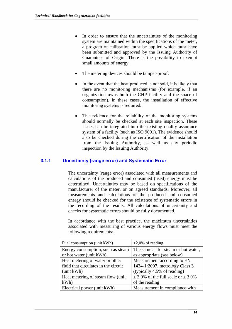
In accordance with the best practice, the maximum uncertainties
associated with measuring of various energy flows must meet the
following requirements:
Fuel consumption (unit kWh) ±2,0% of reading
Energy consumption, such as steam
or hot water (unit kWh) The same as for steam or hot water,
as appropriate (see below)
Heat metering of water or other
fluid that circulates in the circuit
(unit kWh)
Measurement according to EN
1434-1:2007, metrology Class 3
(typically 4.5% of reading)
Heat metering of steam flow (unit
kWh) ± 2,0% of the full scale or ± 3,0%
of the reading
Electrical power (unit kWh) Measurement in compliance with
Technical Handbook for Cogeneration facilities
15
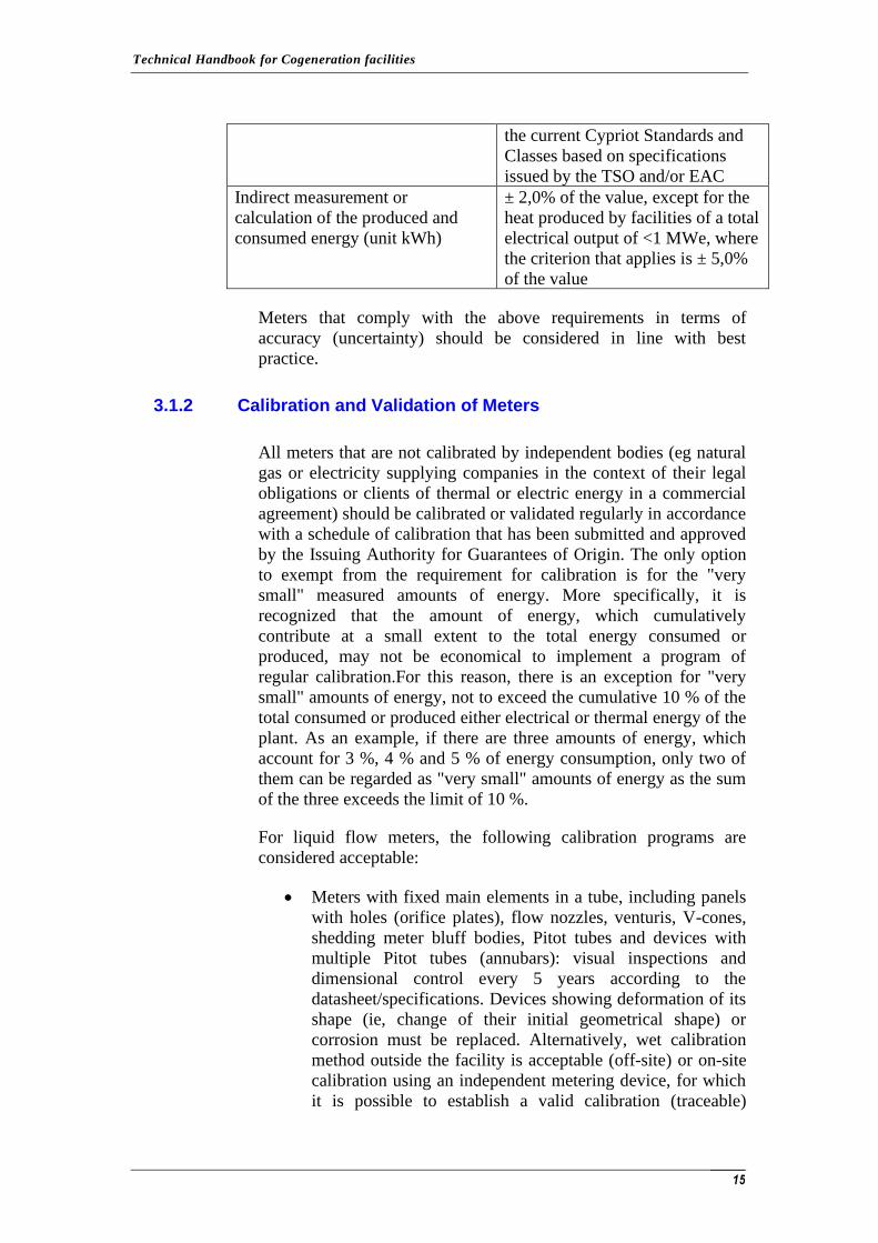
the current Cypriot Standards and
Classes based on specifications
issued by the TSO and/or EAC
Indirect measurement or
calculation of the produced and
consumed energy (unit kWh)
± 2,0% of the value, except for the
heat produced by facilities of a total
electrical output of <1 MWe, where
the criterion that applies is ± 5,0%
of the value
Meters that comply with the above requirements in terms of
accuracy (uncertainty) should be considered in line with best
practice.
3.1.2 Calibration and Validation of Meters
All meters that are not calibrated by independent bodies (eg natural
gas or electricity supplying companies in the context of their legal
obligations or clients of thermal or electric energy in a commercial
agreement) should be calibrated or validated regularly in accordance
with a schedule of calibration that has been submitted and approved
by the Issuing Authority for Guarantees of Origin. The only option
to exempt from the requirement for calibration is for the "very
small" measured amounts of energy. More specifically, it is
recognized that the amount of energy, which cumulatively
contribute at a small extent to the total energy consumed or
produced, may not be economical to implement a program of
regular calibration.For this reason, there is an exception for "very
small" amounts of energy, not to exceed the cumulative 10 % of the
total consumed or produced either electrical or thermal energy of the
plant. As an example, if there are three amounts of energy, which
account for 3 %, 4 % and 5 % of energy consumption, only two of
them can be regarded as "very small" amounts of energy as the sum
of the three exceeds the limit of 10 %.
For liquid flow meters, the following calibration programs are
considered acceptable:
• Meters with fixed main elements in a tube, including panels
with holes (orifice plates), flow nozzles, venturis, V-cones,
shedding meter bluff bodies, Pitot tubes and devices with
multiple Pitot tubes (annubars): visual inspections and
dimensional control every 5 years according to the
datasheet/specifications. Devices showing deformation of its
shape (ie, change of their initial geometrical shape) or
corrosion must be replaced. Alternatively, wet calibration
method outside the facility is acceptable (off-site) or on-site
calibration using an independent metering device, for which
it is possible to establish a valid calibration (traceable)
Technical Handbook for Cogeneration facilities
16
Calibration of secondary devices, such as transducers,
transmitters and computations should be conducted once
every 2 years.
• Meters with moving main elements flow through a tube,
including turbine type meters, and Gilflow type turbine: wet
calibration method outside the facility (off-site) or on-site
calibration using an independent metering device, for which
it is possible to establish a valid calibration (traceable) every
five years. Calibration of secondary elements, such as
transducers, transmitters and computations, should be
conducted once every 2 years.
• Meters without any elements inside the tube, including ultra-
sonic meters, magnetic flow meters and Coriolis meters: wet
calibration method outside the facility (off-site) or on-site
calibration using an independent metering device, for which
it is possible to establish a valid calibration (traceable) every
five years. Calibration of secondary elements, such as
transducers, transmitters and computations, should be
conducted once every 2 years.
• For heat meters supplied as a package that includes a flow
meter, a pair of temperature sensors and a
computer/integrator, recalibration or replacement is needed
by the end of the calibration certificate of the manufacturer.
The new devices or devices that will replace them shall be
equipped with a calibration certificate. Alternatively, wet
calibration method is acceptable outside the facility or in-situ
calibration using an independent counter, for which it is
possible to establish a valid calibration (traceable), every 5
years. Calibration of secondary components, such as
transducers, transmitters and computations, should be
conducted once every 2 years.
• For meters not covered by the above-mentioned cases, an
appropriate program of calibration must be proposed and
submitted for approval by the Issuing Authority Guarantee
of Origin.
For solid fuel meters, including weighbridges, belt weighers and
grab load cells, a calibration program at least once every two years
should be conducted, according to a process by which it is possible
to establish a valid calibration (traceability).
Electricity meters of no more than 500 kWe of power do not require
recalibration during their certification period. Electricity meters of
no more than 500 kWe of power do need recalibration and checking
of accuracy according to predetermined scheduling. For most
Technical Handbook for Cogeneration facilities
17
meters, this means calibration every 10 years (some older
electromechanical meters with 0.5 of accuracy class require
calibration every 3 to 5 years).
In some cases, especially in old industrial facilities, the removal of
meters for inspection may present particular problems, possibly due
to inaccessibility, asbestos or inability to isolate the meter. When
there are a number of similar meters for the same fluid, in similar
measurement conditions, the Guarantee of Origin Issuing Authority
may grant a partial exemption under the following circumstances: if
any of these meters can be inspected and found to be compliant and
“within specifications” after more than 5 years of operation, the
Guarantee of Origin Issuing Authority may grant exemption from
the requirement for inspection of the remaining meters of the same
group for another 5-year period (ie, the sample is representative of
the overall meters), without creating additional uncertainty . In
general, the term "within specifications" means: proper dimensions,
sharp edges (meters aperture) without any distortion of their shape
(ie, change of their initial geometrical shape), buckling, corrosion,
and plugging or blocking of the slots for pressure measurement.
3.2 MEASUREMENT OF FUEL
All fuel consumption should be based on the lower heating value
(Net Calorific Value) and must be measured (kWh).
3.2.1 Fuel categories
Fuels are classified as conventional fuels and alternative fuels.
Natural gas, LPG, gas oil, fuel for commercial use, coal and coke
are considered conventional fuels. Alternative fuels include waste
fuels, fuels which are by-products of other processes, renewable
fuels and recovered heat. Indication of the fraction of total energy
consumption for each fuel must be referred in all cases.
Conventional Fuels
Conventional Fuels include:
• Any gas in a gaseous state, which can be obtained from a gas
utility
• Any gas from the refining of crude oil or other hydrocarbon
gas in liquid state
• Coal and lignite
Technical Handbook for Cogeneration facilities
18
• Coke and semi-coke from coal or lignite
• Petroleum coke
• Fuel oil from the refining of crude oil or petrol used as
propellant
Alternative fuels
All other fuels are considered to be alternative fuels. There are seven
types of alternative fuels:
1. By-products gases: products from industrial processes, for
example blast furnace gas from coking ovens and gas
refineries, which can include elements such as hydrogen,
ethane, propane, etc.
2. Biogas: gas produced from anaerobic digestion of organic
materials (such as sewage, solid waste (to landfill), waste
food processing, pharmaceutical waste and municipal
waste).
3. Gases and Waste heat: waste gases (i.e. carbon monoxide or
volatile organic compounds), or waste heat (such as exhaust
from the high temperature processes, or products of
exothermic chemical reactions).
4. Liquid Biofuels: industrially prepared liquid biofuels, as
defined by EU Directive on biofuels (like biodiesel and
bioethanol ).
5. Liquid waste: materials of biological or non-biological origin
from domestic and industrial activities (such as tallow, fat
and organic oils, used solvents, tank washings, recycled used
oil and bitumen products from refineries).
6. Biomass and Solid Wastes: (such as products from energy
crops, residues from wood processing, municipal solid
waste, industrial waste, hospital waste, agricultural waste,
straw, grain residues, prunings and waste water).
7. Wood fuels: fuels from wood for commercial use (such as
clean wood chips, logs and pellets with the exception of
energy crops and wood waste classified as biomass).
Due to the existence of a wide range of alternative fuels in use, for
the classification of fuels not listed above, please contact the Issuing
Authority Guarantee of Origin. Also, when the determination of the
fuel flow may be conducted in different ways, depending on the
Technical Handbook for Cogeneration facilities
19
design limits of the CHP facility, please contact the Issuing
Authority Guarantee of Origin. For example, when gasification
takes place, the boundary of the installation could be installed at the
feed point with solid fuels of the gasifier. Alternatively, the
boundary could be placed at the point where the produced gas is fed
for combustion or to the reciprocating engine. The measurement
procedure for this requires a different approach.
Imported Steam from an External Supplier (as Equivalent Fuel Consumption )
The steam entered by an external supplier will be treated as a fuel of
the CHP facility. The equivalent amount of fuel will be based on the
heat absorbed during the production of imported steam, assuming
production from water at a temperature of 80°C and pressure of
1.013bar in the boiler with a thermal efficiency of 75% (higher
calorific value - Gross Calorific Value). The referenced fuel should
be based on actual fuel(s) used.
Recovered heat (as Equivalent Alternative Fuel Consumption )
A portion of consumed energy of the steam from the CHP system
can be derived from the processes installation by heat recovery from
exhaust gases produced during the high temperature combustion
processes or by heat recovery from products of the process. That
steam must be used to produce electricity or mechanical energy
within the CHP facility so as to be considered as an energy
consumption of the CHP unit. The recovered heat that simply passes
through the facility so as to be transformed into thermal energy (in
the facility) should not be taken into account in the calculations.
For all waste heat boilers of the within a CHP facility, energy
consumption (ie rejected heat) is treated as consumption of
alternative fuel. The equivalent energy consumption is based on
energy content of steam from the waste heat boiler, having as
reference the energy content of water at a temperature of 10°C and a
pressure of 1,013bar multiplied by a factor of 1.2.
For example, for saturated steam at a pressure of 10 bar (absolute
pressure), specific enthalpy of 2.778 kJ / kg, taken from relevant
tables (with 0° C as a reference point) minus 42 kJ/kg (water at 10°
C and 1,013 bar of pressure) = 2.736kJ/kg x 1,2 = 3.283 kJ/kg
equivalent energy consumption of the boiler = 0,919 MWh/tonne of
steam.
Technical Handbook for Cogeneration facilities
20
3.2.2 Measurement of Gas Fuels
There are a number of specific requirements for measuring gas
consumption by using the metering devices of a utility or a gas
metering device for billing. The quantities of natural gas, supplying
a facility should be recorded by a meter with an uncertainty not
exceeding the limits outlined below:
• Diaphragm gas meters: ± 2% between 2% and 100% of
maximum flow design.
• Other meters: ± 1% between 20% and 100% of maximum
flow design. Also, 2% between the minimum flow design
and less than 20% of maximum flow design.
The following standards may also be used as a reference:
• EN ISO 6976:2005. Natural gas. Calculation of calorific
values, density, relative density and Wobbe index from
composition.
• EN 12405-1:2005. Gas meters. Conversion devices. Volume
conversion.
• EN 12480:2002. Gas meters. Rotary displacement gas
meters.
• EN 12261:2002. Gas meters. Turbine gas meters.
• EN 1359:1998. Gas meters. Diaphragm gas meters.
• AGA-3:1992. Orifice Metering of Natural Gas, Part 3,
Natural Gas. Applications.
• AGA-8:1994. Compressibility Factor of Natural Gas and
Related Hydrocarbon Gases.
However, when local gas meters are used, uncertainty should not be
more than ± 2% of their indication, so as meters be considered in
line with best practice.
Volume measurement should be corrected in terms of temperature
and pressure of gas (at 15°C and 1013,25millibars of absolute
pressure) to allow direct comparison with the facility’s invoiced gas.
Assessment of the time-weighted average values for the calorific
values of gas used should be made.
The calorific value used for the natural gas bills of the supplier is
considered accepted as the true calorific value for the period covered
by each bill. The overall uncertainty of individual gas meters should
not be greater than ± 2%, so as for the meters to be considered in
line with best practice.
Technical Handbook for Cogeneration facilities
21
3.2.3 Measurement of Liquid Fuels
Petroleum products used either as primary or standby fuel should be
monitored and recorded. Petroleum products are usually sold by the
liter. The volume of oil consumed in a facility should be recorded.
This can be achieved using a volume flow meter. Purchase
documentation of fuel may also be used as evidence of oil
consumption, but oil inventories (opening and closing stock) will be
recorded and taken into account. The calorific value declared by the
supplier of the fuel is accepted as the true calorific value of fuel oil
available for commercial use. The total uncertainty of the individual
quantities of petroleum products should not be greater than ± 2%, so
as to be considered in line with best practice.
3.2.4 Measurement of Solid Fuels
The amount of carbon should, where possible, be measured by
weighting belt or other gravimetric methods. The use of carbon for
long periods can be determined by markets and inventories. The
effect of possible errors in the estimation of opening and closing
stocks should be determined. Subsequently, calculation to determine
the total systematic uncertainty associated with energy consumption
of coal is required. As per best practices, the overall uncertainty of
individual energy consumption should not be greater than ± 2%. The
user should ensure that the supplier possesses the proper system of
sampling and analysis for determining the calorific value of
delivered coal. For example, the Standard ISO 13909: Parts 1-8.
Sampling Coal might be adopted. The results should be consistent
with relevant purchase evidence of the carbon. The calorific value
used in the supplier's purchase documentation is accepted as the true
calorific value for fuel supply contract.
3.2.5 Measurement of Consumption of Alternative Fuels
When alternative fuels are used, their energy content must be
determined. In case of imports (consumptions) of heat in the form of
steam, the measurement of the steam flow is needed with same
standard used for the export of the steam. The accurate estimation of
calorific value of some alternative fuels (such as raw municipal
waste) is quite difficult. When the measurement uncertainty of the
energy consumption exceeds ± 2%, indirect methods of calculation
should be considered. The "method losses" is such an example in
combination with a reliable measurement of the energy produced in
order to reduce uncertainty to a lesser degree than ±2%. In this latter
method all the potential losses of CHP facility are added, for
example stack losses, losses shell, etc. Usually, these losses may be
up to ± 5%, so if total losses represent 40% of energy consumption,
Technical Handbook for Cogeneration facilities
22
then the overall uncertainty in determining the performance will be
± 2%. (The method is detailed in the standard "BS 845: Part 2:
1987", and in equivalent DIN or ASME methods). Alternatively, the
higher price of the uncertainty may be used.
Calorific Value of Alternative Fuel
For solid and liquid fuels, the calorific value determined in the
laboratory using bomb-type calorimeter corresponds to the gross
calorific value (GCV) at constant volume. For solid fuels, this is
normally carried out on fuels that have been dried with air (ie a
sample of fuel is allowed to dry in equilibrium with its environment
in a dry and well ventilated environment). Due to the fact that the
residual (inherent) moisture in the sample affect the determination
of calorific value, moisture is determined separately by drying the
sample at 105°C in an oven until there is no further weight loss.
Then, a correction factor is applied so as to obtain the higher
calorific value of dry fuel.
For gaseous fuels, the calorific value determined in the laboratory
using gas fuel calorimeter corresponds to the higher calorific value
at constant pressure. The calculation of the calorific value of gas
fuels, based on typical calorific values of constituents of the gas fuel
and the advanced analytical techniques available, has largely
replaced the use of fuel gas calorimeters.
The distinction between higher (GCV) and lower/net calorific value
(NCV) is important. In determining the higher calorific value, the
products of combustion are cooled at a temperature of 15°C. This
means that virtually all water vapor condenses into liquid water
either formed by the combustion of fuel’s hydrogen or by the
evaporation of moisture. This condensation releases latent heat
which is included therefore in the determination of the higher
calorific value. Proponents of the lower calorific value argue that,
due to the fact that this latent heat can be recovered in burners
installations as boilers, it should be removed accordingly. This leads
the lower calorific value be more representative of the heat
generated in operation during the combustion process.
The difference between higher (GCV) and lower/net calorific value
(NCV) depends on the content of fuel in moisture and hydrogen. For
natural gas, which is dry and composed primarily of methane (25%
by weight in hydrogen and 75% in carbon), the net calorific value is
about 10% less than the higher calorific value. For most of the dry
fuels, the difference is less than 10%, typically 4% - 6% for coal and
petroleum fuels, but may be much higher for fuels containing high
moisture content. For wood containing 60% moisture, the ratio of
Technical Handbook for Cogeneration facilities
23
net calorific value to the corresponding value of the higher calorific
value (NCV/GCV) is approximately 0.75.
Determination of calorific value of Alternative Fuels
For alternative gaseous fuels, the continuous chromatography
analysis of the gas fuel or with equivalent instrument is
recommended, using processing techniques to determine the
stoichiometric analysis and calorific value. In case of moisture
removal from the sample prior to analysis, quantification of
moisture should be done in order to determine the calorific value in
‘as-fired’ conditions. In the absence of continuous analysis, samples
must be taken from the feed line for laboratory analysis with
sufficient frequency to maintain a reliable record of the calorific
values.
For alternative solid and liquid fuels, the calorific value should be
determined by calorimetry using samples collected and prepared in
accordance with appropriate standards. The determination of the
fuel content in moisture in ‘as-fired’ conditions is also needed. It is
estimated that a representative sampling of some alternative solid
fuels has some considerable practical difficulties. However, even if
an alternative approach described hereunder is accepted, a support
system for sampling and analysis is required, including
determination of moisture content.
For solid and liquid fuels, an alternative solution to calorimetry is
the stoichiometric fuel analysis which in turn relies on
representative sampling. This requires for the determination of the
fuel content in carbon, hydrogen, sulfur, oxygen and nitrogen. This
analysis can then be used in conjunction with an empirical analytical
formula for the calculation of the higher calorific value of fuel in dry
(GCVdry).
Such an analytical formula, widely adopted for biofuels, has been
published in the "Coal Conversion Systems: Technical Data Book"
(1978) by the US Institute of Gas Technologies (IGT). Although the
detailed formula originated from data on coal, acceptable results
have been published for a wide range of carbonaceous materials
including biomass and other fuels.
GCVdry, MJ/kg = 0,341C + 1,322H – 0,12(O+N) + 0,0686S -
- 0,0153Ash
Where: GCVdry, = higher calorific value of the fuel in dry
C = carbon weight (% ) in dry fuel
H = hydrogen weight (% ) in dry fuel
Technical Handbook for Cogeneration facilities
24
O = oxygen weight (% ) in dry fuel
N = nitrogen weight (% ) in dry fuel
S = sulphur weight ( % ) in dry fuel
Ash = ash weight ( % ) in dry fuel
For alternative solid fuels, particularly biomass, a vast amount of
published data is available. The Research Committee on Industrial
and Municipal Waste of the American Society of Mechanical
Engineers (ASME) published two reports in 1974 and 1978. This
work was extended in 1986 under the auspices and funding of the
Office of Technology Renewable Energy of the US Department of
Energy, providing information on more than 600 substances in a
report entitled "Thermodynamic Data for Biomass Conversion and
Waste Incineration" by the Solar Energy Research Institute,
published later on by ASME. This report can be found in the Office
of Scientific and Technical Information (OSTI) of the U.S.
Department of Energy in http://www.osti.gov/bridge, with an id of
7038865.
The Energy Research Centre of the Netherlands (ECN) maintains
the "PHYLLIS" database which is populated with data for biomass
and waste (http://www.ecn.nl/phyllis). This database contains
information on some 2,400 substances, including the calorific value
based on the calorimetry and calculated from the stoichiometric
analysis. The database makes use of the aforementioned IGT
analytic formula for calculating the calorific value, (also referred to
as the ‘Milne’ analytic formula after one of the authors of the DoE
reports).
Expressions of Calorific Value of Alternative Fuels and Conversions
The higher calorific value in as-fired conditions (GCVaf)
incorporates the content of the fuel moisture levels in the CHP
facility. Oftentimes, the term ‘as-received’ regarding the higher
calorific value is used (GCVar), meaning the higher heating value of
the sample of fuel received by the laboratory (prior of any treatment
takes place); this takes into account the content of this moisture.
Assuming that there is no difference in moisture content between
the stockpile and the sample of the laboratory, both calorific values
are identical. For consistency with other sources of literature, the
above-mentioned approach is considered as correct; the abbreviation
GCVar (higher calorific value ‘as-received’) will be used instead of
the GCVaf. (higher calorific value in ‘as-fired’ conditions).
Technical Handbook for Cogeneration facilities
25
The majority of analytical methods for solid fuels are made on air-
dried samples until equilibrium with the atmosphere of the
laboratory is reached. Although these results are referred to air-dried
conditions (ad), it often need to be converted as in dry, in dry ash-
free (daf) or, rarely for biomass purposes, in dry mineral matter-free
(dmmf).
The higher calorific value ‘as-received’ (GCVar) can be calculated if
the higher calorific value in dry (GCVdry) or in dry ash-free
(GCVdaf) is known, as follows:
GCVar = GCVdry × (100 – m) / 100
GCVdry = GCVdaf × (100 - Ashdry) / 100
Where:
m = content by weight (%) of the fuel in moisture (‘as-
received’) = 100 × moisture weight/(weight of dry fuel
+ weight of moisture)
Ashdry = ash weight (%) of the fuel (dry basis)
According to the EU Directive the conversion of net calorific values
(NCV) should be possible for evaluation and reporting purposes of a
CHP facility.
For the following conversions to be applicable, the content of the
fuel into hydrogen, ash and moisture must be known
GCVdry = NCVdry + (2.442 × 8.936 × Hdry) / 100
NCVdry = GCVdry - (2.442 × 8.936 × Hdry) / 100
NCVar = NCVdry × (100 – m) / 100 – 2.442 × m / 100
NCVdry = NCVdaf × (100 – Ashdry) /100
Where:
GCV = higher calorific value, MJ/kg
NCV = lower/net calorific value, MJ/kg
m = moisture weight (% ) of fuel in ("as-received")
Hdry = hydrogen weight (% ) of the fuel (in dry basis)
2.442 = latent heat of vaporization of water at 25C,
MJ/kg
Technical Handbook for Cogeneration facilities
26
8.936 = kg of water formed by combusting 1kg of
hydrogen
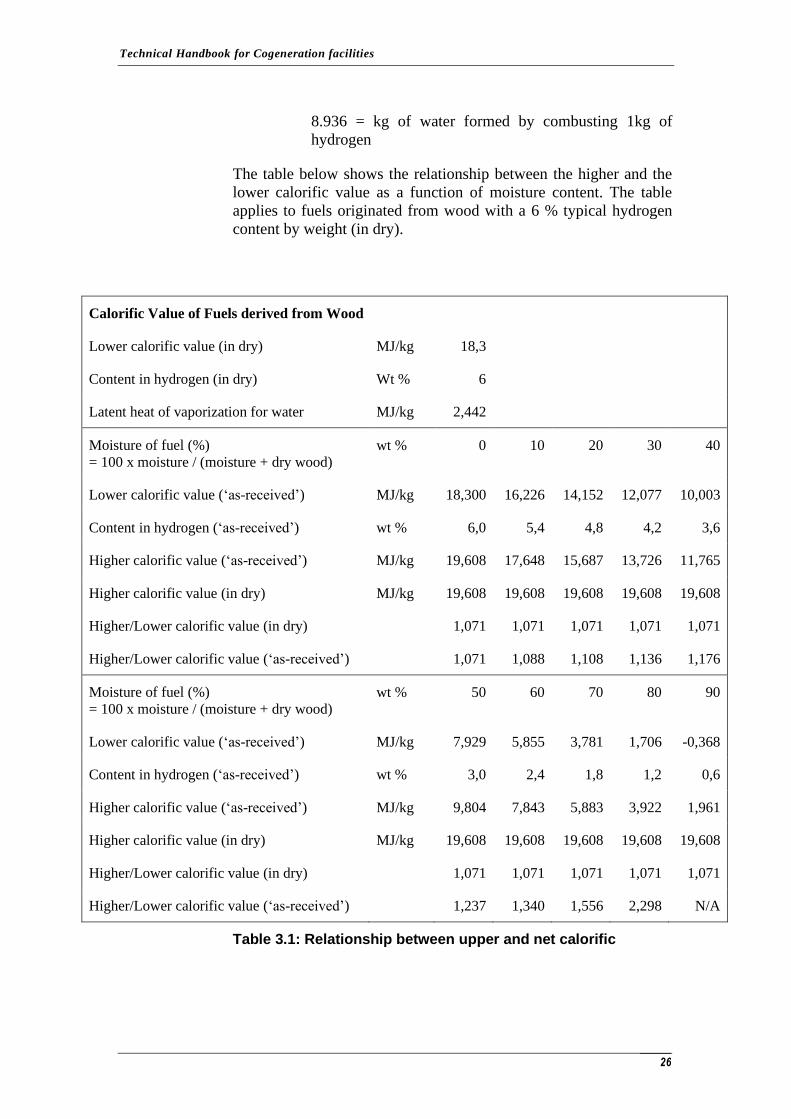
The table below shows the relationship between the higher and the
lower calorific value as a function of moisture content. The table
applies to fuels originated from wood with a 6 % typical hydrogen
content by weight (in dry).
Calorific Value of Fuels derived from Wood
Lower calorific value (in dry) MJ/kg 18,3
Content in hydrogen (in dry) Wt % 6
Latent heat of vaporization for water MJ/kg 2,442
Moisture of fuel (%)
= 100 x moisture / (moisture + dry wood)
wt % 0 10 20 30 40
Lower calorific value (‘as-received’) MJ/kg 18,300 16,226 14,152 12,077 10,003
Content in hydrogen (‘as-received’) wt % 6,0 5,4 4,8 4,2 3,6
Higher calorific value (‘as-received’) MJ/kg 19,608 17,648 15,687 13,726 11,765
Higher calorific value (in dry) MJ/kg 19,608 19,608 19,608 19,608 19,608
Higher/Lower calorific value (in dry) 1,071 1,071 1,071 1,071 1,071
Higher/Lower calorific value (‘as-received’) 1,071 1,088 1,108 1,136 1,176
Moisture of fuel (%)
= 100 x moisture / (moisture + dry wood)
wt % 50 60 70 80 90
Lower calorific value (‘as-received’) MJ/kg 7,929 5,855 3,781 1,706 -0,368
Content in hydrogen (‘as-received’) wt % 3,0 2,4 1,8 1,2 0,6
Higher calorific value (‘as-received’) MJ/kg 9,804 7,843 5,883 3,922 1,961
Higher calorific value (in dry) MJ/kg 19,608 19,608 19,608 19,608 19,608
Higher/Lower calorific value (in dry) 1,071 1,071 1,071 1,071 1,071
Higher/Lower calorific value (‘as-received’) 1,237 1,340 1,556 2,298 N/A
Table 3.1: Relationship between upper and net calorific
Technical Handbook for Cogeneration facilities
27
Determination of Energy Consumption of Alternative Fuels
Whenever possible, energy consumption must be calculated as
follows:
Energy consumption, MJ = Amount of fuel to burn, kg ×
NCVar, MJ/kg
Energy consumption, MWh = Energy consumption MJ / 3,60
Three requirements should be met:
• Measuring the amount of fuel
For solid and liquid fuels, an acceptable method for
measuring fuel consumption based on data from deliveries of
goods (weighbridge sheets) and opening and closing stocks,
unless there is a change in moisture content of the stock, eg
drainage of (sold) waste. Other methods for measuring solid
fuels include belt weighers and grab weighers, provided that
such equipment is properly calibrated.
For liquid and gaseous fuels, it is appropriate to measure the
flow in the duct (tube) with proper calibration.
• Measurement and reliable data on the calorific value
Reliable data on the calorific value for all the fuels are
needed. In cases where the fuel is fairly homogeneous, this
can be readily done through regular sampling and analysis,
or through continuous gas analysis. However, for certain
solid fuels, the very nature of the fuel makes the
representative sampling and/or the sample preparation a
difficult issue. In the case of municipal solid waste, fuels
derived after treatment of solid waste (Refuse Derived Fuel -
RDF) and secondary fuel from waste (Secondary Refuse
Fuel - SRF), the composition of the waste may need to be
determined (eg paper, cardboard, organic materials, various
plastics, wood, diapers etc). The calorific value of the
components can then be determined from relevant databases.
Data for the moisture content are required, as well. The
standard "EN 14899:2005 Characterisation of Waste -
Sampling of Waste Materials - Framework for the
preparation and application of a sampling plan" deals with
these issues.
• Measurement of moisture content
Technical Handbook for Cogeneration facilities
28
For solid and liquid fuels to reliable collection of data on the
moisture content is necessary so as the calorific value be
calculated. This is particularly important when the moisture
content of fuels is not constant. For non-homogeneous fuels
elements for the moisture content of their components are
required.
For fuel that the measurement of the mass flow or the determination
of a representative calorific value is not possible, a more reliable
value of the energy consumption may be determined through
method losses. This method requires data on the sulfur content of
fuel moisture and recording of the produced steam from the boiler.
It also requires a regular measurement and recording of temperature
and oxygen content of exhaust gases from the boiler. The
application of this method depends on the design of each boiler ( eg
air preheaters, air purifiers of the boiler surfaces from ash residues
(blowdown), heating processes of water supply ). Potential users of
this method must present the calculation method, all relevant
information and a spreadsheet by way of example for prior approval
to the Issuing Authority Guarantee of Origin.
For all energy consumptions, the uncertainty associated with the
used price need to be calculated. In addition, all meter used to
determine the energy consumption should be calibrated at regular
intervals in compliance with the schedule agreed upon.
3.2.6 Metering of Fuel Side-streams
In some cases, the total fuel consumption in the boundaries of the
facility and a small fuel flow side-stream use (to another user
outside the boundaries of the facility), is monitored using a single
meter. In these cases, since there is no separate measurement of each
fuel stream (as required), the person responsible for the facility
should contact the Issuing Authority for Guarantees of Origin to
find ways of tackling the problem.
3.2.7 Fuels with Variable Moisture Content
The calorific value of fuel varies significantly depending on the
moisture content. This is particularly important for fuels such as
solid waste (eg untreated household waste), wood waste and other
biofuels. For this reason, the calorific value usually refers to the dry
substance, and in most cases this is the net calorific value.
Dry wood waste, as an example, can have a lower calorific value in
dry equal to 18,3 MJ/kg. It can be shown that the higher calorific
value in dry (MJ / kg) equals the sum of the net calorific value in
Technical Handbook for Cogeneration facilities
29
dry and the product of 0.218×H%, where H is the content by weight
of dry wood to hydrogen (typically 6%). This leads to a higher
calorific value (dry) equivalent to 19,608 MJ/kg.
Considering that the content by weight of moisture can be
determined on a regular basis as a percentage (%) of the total weight
of the fuel (to burn) in wet, the energy consumption on a higher
calorific value can be calculated as follows:
• Given data:
Higher Calorific Value (in dry) =
19,608 MJ/kg = 19,608 GJ/tonne
Amount of liquid fuel (F) = 200 tonnes (for example)
Moisture content (M) = 60% of the total amount of fuel (for
example)
• Calculations:
Amount of fuel in dry = F (100 – M) / 100 = 200 (100 –
60) / 100 = 80 tonnes
Energy consumption (in higher calorific value) = 80
19,608 = 1.568,64 GJ = 1.568,64 / 3,6 = 435,73 MWh
3.3 MEASUREMENT OF THE ELECTRICITY PRODUCED
For the purposes of the Guarantee of Origin system, the total
electricity (MWh) generated by a cogeneration facility is measured
at the terminals of the generator, without removing any own
consumption for the operation of the cogeneration facility per se.
The total electricity also incorporates the mechanical energy which
is converted into equivalent electrical energy.
That is:
CHP Total Power Output = Power Output + Electrical Equivalent
Output
Where:
Electrical Equivalent Output =
Mechanical Power × 1.05
Technical Handbook for Cogeneration facilities
30
3.3.1 Mechanical Power Outputs
Most of the electricity within a CHP facility for own consumption
purposes is used to power electric motors that drive pumps, fans,
compressors, etc. The losses in a CHP facility in converting
mechanical energy into electricity and then back into mechanical
energy to directly drive a pump, a fan or a compressor may be
avoided. To reflect this energy savings compared with conventional
approaches, the generated mechanical energy is treated as equivalent
electrical energy. These savings are included in the calculation of
electricity, multiplying the mechanical energy by a factor of 1.05 to
produce the equivalent electrical energy. However, the direct
measurement of the produced energy of the shaft is not feasible
when the mechanical energy is generated by a motor of the CHP
facility.
The mechanical power used within a CHP facility for the driving
systems that are integral to the function of the motors of the facility
(eg gas turbine compressor) should not be included in the produced
mechanical power outputs of the CHP facility for the Guarantee of
Origin purposes. This amount of energy is included in the generated
energy in the shaft and the produced heat of the engine.
The mechanical power used within a CHP facility, for the rest of the
driving systems may be included in the mechanical outputs of the
CHP facility for Guarantees of Origin purposes. The driving engine
can also be an electric motor. These systems can include pumps for
feed-water of the boiler propelled by steam turbine, pumps for
cooling water and air compressors. For these purposes, the energy
used by electric motors has already been taken into account, since
the produced electrical energy of CHP facility is measured at the
generator terminals.
3.3.2 Meter location
As already mentioned, electricity generated by a cogeneration
facility is measured at the terminals of the generator, without
removing any of the domestic consumption for the operation of the
cogeneration facility.
3.3.3 Meteriung Requirements
Electrical Power
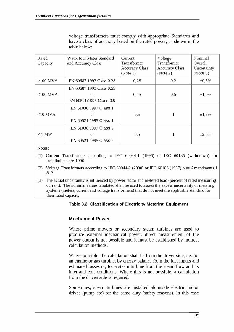
For metering electricity, commercial/industrial three-phase meters
should be used certified for billing; their characteristics should also
be explicitly visible and readable. The energy meters, current and
Technical Handbook for Cogeneration facilities
31
voltage transformers must comply with appropriate Standards and
have a class of accuracy based on the rated power, as shown in the
table below:
Rated
Capacity
Watt-Hour Meter Standard
and Accuracy Class
Current
Transformer
Accuracy Class
(Note 1)
Voltage
Transformer
Accuracy Class
(Note 2)
Nominal
Overall
Uncertainty
(Note 3)
>100 MVA EN 60687:1993 Class 0.2S 0,2S 0,2 ±0,5%
<100 MVA
EN 60687:1993 Class 0.5S
or
EN 60521:1995 Class 0.5
0,2S 0,5 ±1,0%
<10 MVA
EN 61036:1997 Class 1
or
EN 60521:1995 Class 1
0,5 1 ±1,5%
≤ 1 MW
EN 61036:1997 Class 2
or
EN 60521:1995 Class 2
0,5 1 ±2,5%
Notes:
(1) Current Transformers according to IEC 60044-1 (1996) or IEC 60185 (withdrawn) for
installations pre-1996
(2) Voltage Transformers according to IEC 60044-2 (2000) or IEC 60186 (1987) plus Amendments 1
& 2
(3) The actual uncertainty is influenced by power factor and metered load (percent of rated measuring
current). The nominal values tabulated shall be used to assess the excess uncertainty of metering
systems (meters, current and voltage transformers) that do not meet the applicable standard for
their rated capacity
Table 3.2: Classification of Electricity Metering Equipment
Mechanical Power
Where prime movers or secondary steam turbines are used to
produce external mechanical power, direct measurement of the
power output is not possible and it must be established by indirect
calculation methods.
Where possible, the calculation shall be from the driver side, i.e. for
an engine or gas turbine, by energy balance from the fuel inputs and
estimated losses or, for a steam turbine from the steam flow and its
inlet and exit conditions. Where this is not possible, a calculation
from the driven side is required.
Sometimes, steam turbines are installed alongside electric motor
drives (pump etc) for the same duty (safety reasons). In this case
Technical Handbook for Cogeneration facilities
32
trials using the motor-driven machine may provide the required
information.
3.4 MEASUREMENT OF USEFUL HEAT PRODUCED
The useful heat supplied by a CHP facility is the heat generated in a
cogeneration process to satisfy an economically justifiable demand
for heating or cooling. It is this heating or cooling, according to
market conditions that is demonstrably utilised to displace heat that
would otherwise be supplied from other sources.
Usually, for CHP facilities over 1MWe, heat outputs will be in the
form of steam to meet various needs (eg industrial processes,
heating etc ). Other heat outputs may be hot water or heat transfer
oil circulating systems that are used to transport heat for process or
space heating. Some CHP facilities use part or all of the exhaust
gases from a gas turbine or engine for direct heating or drying
applications. CHP facilities may provide heat at various pressure
(steam) and temperature (steam, hot water) levels and the energy
output is the sum of these heat energy outputs.
The useful heat supplied by a CHP facility excludes heat rejected to
the environment without any beneficial use. Examples include, inter
alia, heat lost from chimneys or exhausts and heat rejected in
equipment such as condensers and air coolers.
Heat from steam can be used within the CHP facility before the
steam is supplied to the process, and can also be returned to the
CHP facility from the process as condensate after the steam has
given up most, but not all, of its useful energy. Generally, the aim is
to determine the useful heat supplied to the process (i.e. excluding
the heat rejected in condensers, heat rejection radiators, and other
facilities) and to encourage the use of heat from condensate. With
this objective in view:
• Where steam is used for duties such as deaeration,
condensate heating, make-up water and boiler feed-water
heating, this should not be counted as part of the useful heat
supplied to site.
• Recovery of heat from condensate, and re-use of condensate
in a closed loop steam network, is obviously best practice
where possible. Excluding condensate heat from the total
heat supplied to the user would tend not to encourage the
recovery of heat from condensate. Therefore, the heat
content of condensate return is not subtracted from the useful
heat figure in determining the CHP facility’s heat outputs.
Technical Handbook for Cogeneration facilities
33
• Steam used for injection into gas turbines is not useful heat
supplied to process, due to the fact that this value of this
energy is reflected in increased power output and exhaust
gas mass flow
The heat content of steam supplied to the process is to be
determined relative to a mean ambient temperature datum and a
pressure datum. These two parameters will be taken as 10C (50F)
and 1.013bar (according to the practice in many European
countries). So the specific heat content (specific enthalpy) equals the
specific enthalpy from steam tables or steam charts, which have a
datum of 0C (32F) and 1.013bar, minus the specific enthalpy of
water at 10C and 1.013bar on the same basis.
For example:
Saturated steam at the facility under 10bar ~
specific enthalpy (0°C) = 2778kJ/kg
Water at 10°C ~
specific enthalpy (0°C) = 42kJ/kg
Heat the installation ~
specific enthalpy (10°C) = 2778-42 = 2736kJ/kg
Where exhaust gases are used for direct heating applications, the
useful heat output is the difference in heat content of the exhaust
gases between entering and leaving the application.
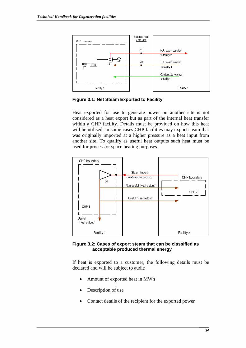
3.4.1 Heat Transfer and Net Heat Exports from a Facility
For a CHP facility that supplies one or more external heat
customers, the useful heat exported is the net transfer of heat across
site boundaries (i.e. heat supplied minus heat returned), excluding
condensate return. For example a CHP facility may export steam to
another site and receive some or all of this back within the facility
boundary as steam at a reduced pressure or as condensate. In this
case the useful heat is the energy content of the steam exported (Q1
see Fig 3.1) minus the energy content of the steam returned (Q2),
both relative to a datum of water at ambient temperature. The heat
content in any condensate returned will not be deducted from the
heat supplied.
Technical Handbook for Cogeneration facilities
34
Figure 3.1: Net Steam Exported to Facility
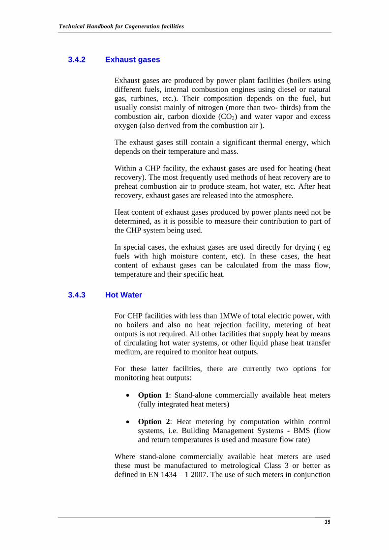
Heat exported for use to generate power on another site is not
considered as a heat export but as part of the internal heat transfer
within a CHP facility. Details must be provided on how this heat
will be utilised. In some cases CHP facilities may export steam that
was originally imported at a higher pressure as a heat input from
another site. To qualify as useful heat outputs such heat must be
used for process or space heating purposes.
Figure 3.2: Cases of export steam that can be classified as acceptable produced thermal energy
If heat is exported to a customer, the following details must be
declared and will be subject to audit:
• Amount of exported heat in MWh
• Description of use
• Contact details of the recipient for the exported power
Technical Handbook for Cogeneration facilities
35
3.4.2 Exhaust gases
Exhaust gases are produced by power plant facilities (boilers using
different fuels, internal combustion engines using diesel or natural
gas, turbines, etc.). Their composition depends on the fuel, but
usually consist mainly of nitrogen (more than two- thirds) from the
combustion air, carbon dioxide (CO2) and water vapor and excess
oxygen (also derived from the combustion air ).
The exhaust gases still contain a significant thermal energy, which
depends on their temperature and mass.
Within a CHP facility, the exhaust gases are used for heating (heat
recovery). The most frequently used methods of heat recovery are to
preheat combustion air to produce steam, hot water, etc. After heat
recovery, exhaust gases are released into the atmosphere.
Heat content of exhaust gases produced by power plants need not be
determined, as it is possible to measure their contribution to part of
the CHP system being used.
In special cases, the exhaust gases are used directly for drying ( eg
fuels with high moisture content, etc). In these cases, the heat
content of exhaust gases can be calculated from the mass flow,
temperature and their specific heat.
3.4.3 Hot Water
For CHP facilities with less than 1MWe of total electric power, with
no boilers and also no heat rejection facility, metering of heat
outputs is not required. All other facilities that supply heat by means
of circulating hot water systems, or other liquid phase heat transfer
medium, are required to monitor heat outputs.
For these latter facilities, there are currently two options for
monitoring heat outputs:
• Option 1: Stand-alone commercially available heat meters
(fully integrated heat meters)
• Option 2: Heat metering by computation within control
systems, i.e. Building Management Systems - BMS (flow
and return temperatures is used and measure flow rate)
Where stand-alone commercially available heat meters are used
these must be manufactured to metrological Class 3 or better as
defined in EN 1434 – 1 2007. The use of such meters in conjunction
Technical Handbook for Cogeneration facilities
36
with an appropriate calibration schedule will not require any
adjustment for excessive uncertainty.
Heat metering may be achieved by computation within control
systems such as BMS or Distributed Control System (DCS), using
measured flow and return temperatures and the measured fluid
circulation rate. It should be noted that the use of thermocouples to
EN 60584-1:1996/IEC 60584-1:1995 and EΝ 60584-2:1993 for
fluid temperature measurements and temperature differential is
likely to lead to excessive uncertainty unless a lesser uncertainty can
be established by calibration. For such measurements matched pairs
of platinum resistance thermometers to EN 60751:1996/IEC
60751:1983 are preferred.
3.4.4 Steam
For measurement of steam mass flow and energy content, meters
with an overall uncertainty of ±2.0% of full-scale or ±3.0% of actual
readings are required. Where appropriate, correction for steam
pressure and temperature (superheated steam only) is required. The
additional uncertainties associated with these corrections and other
elements of the measuring system are included in the overall
uncertainty.
Orifice plates, nozzles and venturi tubes should be designed and
installed in accordance with EN ISO 5167 Parts 1 to 4:2003 or
equivalent, and the mass flow calculation should be based on actual
(not nominal) dimensions.
The calculation of overall uncertainty should take into account the
individual uncertainties associated with; (i) the installed orifice
plate, nozzle or venturi system; (ii) the measurement of the
differential pressure, static steam gauge pressure and steam
temperature; and (iii) the transmitters and integrator errors etc. The
additional uncertainties associated with these corrections and other
elements of the measuring system may increase the overall
uncertainty for measuring steam output mass flow to ±2.0% of full-
scale or ±3.0% of actual reading.
Other types of flow meter capable of the required accuracy or better
are permitted. Dimensions and condition of orifice plates should be
checked and other primary flow devices, transmitters and signal
processing should be regularly calibrated as part of an agreed
calibration schedule. There are no standards for calibrating
differential pressure gauges, but these should be calibrated, by
appropriate accredited bodies Other devices should also be
appropriately calibrated, for example, static pressure gauges in line
with EN 837-1:1998 ‘Pressure gauges – Bourdon tube pressure
Technical Handbook for Cogeneration facilities
37
gauges – Dimensions, metrology, requirements and testing’, and
temperature sensors in line with EN 60584-1:1996 ‘Thermocouples.
Reference tables’.
Evidence of calibrations of steam (or heat) flow meters, including
the primary flow device, should be available in case of audit of the
site.
Metering of all steam and heat flows that contribute to the useful
energy outputs of the CHP facility is required. This may involve
metering steam at several pressure levels. Metering stations must be
located so that the steam used for parasitic heat loads within the
CHP facility (e.g. deaeration and feed-water heating or gas turbine
steam injection) are excluded and steam that is dumped to
atmosphere is also excluded. If the main meter includes any such
elements, these must be metered separately and deducted from the
heat outputs.
Dispensation from metering minor steam (or heat) flows: A
calculation of minor steam (or heat) flows less than 10%
(cumulatively) of total useful heat output from the facility may be
permitted providing that any such calculations are based on reliable
data and the associated uncertainty can be determined.
3.4.5 Direct Use of Heat
In some industrial processes, heat exhaust from the turbine or
internal combustion engine is used directly for drying purposes.
There are several methods that can be used to determine the useful
heat. Interested parties should submit information on the proposed
method. The basic principle is that all calculations must be based on
reliable data and that the overall uncertainty associated with the
calculation results can be determined.
Technical Handbook for Cogeneration facilities
38
4 STANDARDS
AGA-3:1992. Orifice Metering of Natural Gas, Part 3, Natural Gas.
Applications.
AGA-8:1994. Compressibility Factor of Natural Gas and Related
Hydrocarbon Gases.
ASME PTC 4.4:1992. Gas Turbine Heat Recovery Steam
Generators.
BS 845-1:1987. Methods for assessing thermal performance of
boilers for steam, hot water and high temperature heat transfer
fluids. Concise procedure.
BS 845-2:1987. Methods for assessing thermal performance of
boilers for steam, hot water and high temperature heat transfer
fluids. Comprehensive procedure.
EN 837-1:1998. Pressure gauges. Bourdon tube pressure gauges.
Dimensions, metrology, requirements and testing.
EN 837-2:1998. Pressure gauges. Selection and installation
recommendations for pressure gauges.
EN 1359:1998. Gas meters. Diaphragm gas meters.
EN 1434-1:2007. Heat meters - Part 1: General requirements.
EN 12261:2002. Gas meters. Turbine gas meters.
EN 12405-1:2005. Gas meters. Conversion devices. Volume
conversion.
EN 12480:2002. Gas meters. Rotary displacement gas meters.
EN 14899:2005. Characterisation of Waste - Sampling of Waste
Materials - Framework for the preparation and application of a
sampling plan.
EN 60521:1995. Class 0.5, 1, and 2 alternating-current watt-hour
meters.
EN 60584-1:1996. Thermocouples. Reference tables.
EN 60584-2:1993. Thermocouples. Tolerances
Technical Handbook for Cogeneration facilities
39
EN 60687:1993. Alternating current static watt-hour meters for
active energy (classes 0.2 S and 0.5 S).
EN 60751:1996. Industrial platinum resistance thermometer sensors.
EN 61036:1997. Alternating current static watt-hour meters for
active energy (classes 1 and 2).
EN ISO 5167-1:2003. Measurement of fluid flow by means of
pressure differential devices inserted in circular cross-section
conduits running full - Part 1: General principles and requirements.
EN ISO 5167-2:2003. Measurement of fluid flow by means of
pressure differential devices inserted in circular cross-section
conduits running full - Part 2: Orifice plates.
EN ISO 5167-3:2003. Measurement of fluid flow by means of
pressure differential devices inserted in circular cross-section
conduits running full - Part 3: Nozzles and Venturi nozzles.
EN ISO 5167-4:2003. Measurement of fluid flow by means of
pressure differential devices inserted in circular cross-section
conduits running full - Part 4: Venturi tubes.
EN ISO 6976:2005. Natural gas. Calculation of calorific values,
density, relative density and Wobbe index from composition.
IEC 60044-1:1996. Instrument transformers - Part 1: Current
transformers.
IEC 60044-2:2000. Instrument transformers - Part 2: Inductive
voltage transformers.
IEC 60185 (withdrawn). Current Transformers.
IEC 60186:1987. Voltage Transformers.
IEC 60584-1:1995. Thermocouples - Part 1: Reference tables.
IEC 60751:1983. Industrial platinum resistance thermometer
sensors.
ISO 3966:1977. Measurement of fluid flow in closed conduits -
Velocity area method using Pitot static tubes.
ISO 9096:2003. Stationary source emissions - Manual determination
of mass concentration of particulate matter.
ISO 10780:1994. Stationary Source Emission - Measurement of
Velocity and Volume Flow Rate of Gas Streams in Ducts.
Technical Handbook for Cogeneration facilities
40
ISO 12039:2001. Stationary source emissions - Determination of
carbon monoxide, carbon dioxide and oxygen - Performance
characteristics and calibration of automated measuring systems.
ISO 13909: Parts 1-8. The Hard Coal Sampling Standard.
ISO 14164:1999. Stationary source emissions - Determination of the
volume flowrate of gas streams in ducts - Automated method.
US EPA Method 4. Determination of Moisture Content in Stack
Gases.
Notes:
• The term AGA refers to the American Gas Association.
• The term ASME refers to the American Society of
Mechanical Engineers.
• The term BS refers to the British Standards Institution.
• The term CEN refers to the European Committee for
Standardization.
• The term EN refers to the European Standards Organisation.
• The term IEC refers to the International Electrotechnical
Commission.
• The term ISO refers to the International Standards
Organisation.
• The term US EPA refers to the Methods of the United States
Environmental Protection Agency as listed in the Code of
Federal Regulations 40.

Technical Handbook for Cogeneration facilities
41
ANNEX I
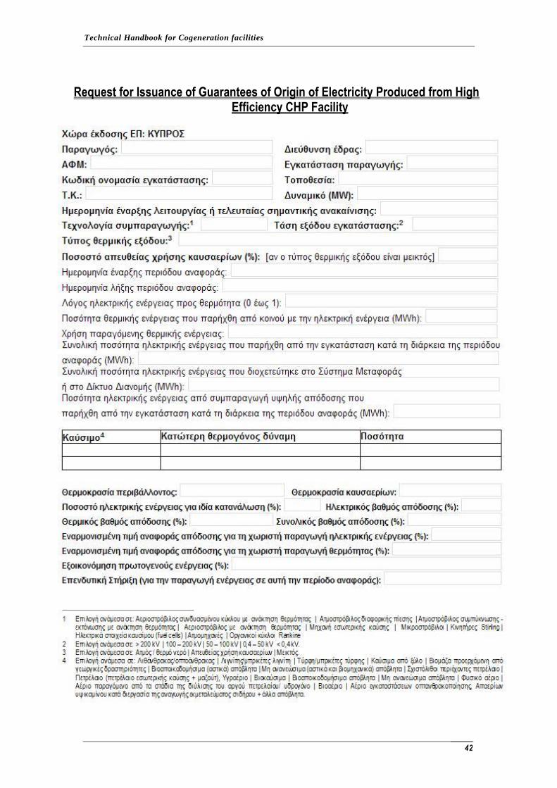
Technical Handbook for Cogeneration facilities
42
Request for Issuance of Guarantees of Origin of Electricity Produced from High Efficiency CHP Facility

Technical Handbook for Cogeneration facilities
43
ANNEX II
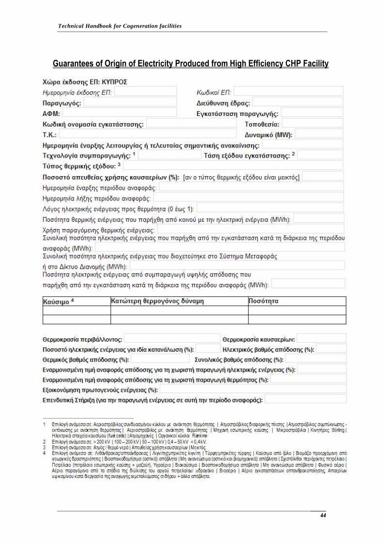
Technical Handbook for Cogeneration facilities
44
Guarantees of Origin of Electricity Produced from High Efficiency CHP Facility