Embed Size (px)
Citation preview
1
TECHNICAL HANDBOOKISC INDUSTRIAL HARDWARE SYSTEM
EN. 3.1
Multilanguage (EN, DE, NL, FR, PL)

2
INTRODUCTION
This technical handbook is a tool to assist you with understanding all the technical features, dimensions and application of the FlexiForce ISC hardware system for industrial doors. For customers that either produce hardware sets in their own door production. But also for customers that outsource the hardware set
production to their nearest FlexiForce subsidiary. In this booklet you will find a description of our set-up for complete hardware sets. The different available lift systems, possibilities and built-in situations.
We have added also some basic explanations on industrial overhead doors and building specifications. For actual pricing and ordering information, we refer to our separate price list for ISC industrial hardware sets. If you have any questions, please do not hesita-
te to contact our sales team for assistance or find more details on: www.flexiforce.com
3
INTRODUCTION
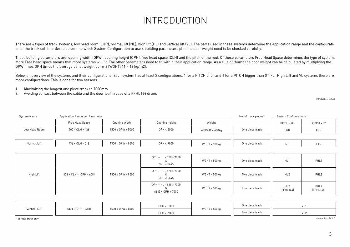
There are 4 types of track systems, low head room (LHR), normal lift (NL), high lift (HL) and vertical lift (VL). The parts used in these systems determine the application range and the configurati-on of the track set. In order to determine which System Configuration to use 4 building parameters plus the door weight need to be checked carefully. These building parameters are; opening width (OPW), opening height (OPH), free head space (CLH) and the pitch of the roof. Of these parameters Free Head Space determines the type of system. More Free head space means that more systems will fit. The other parameters need to fit within their application range. As a rule of thumb the door weight can be calculated by multiplying the OPW times OPH times the average panel weight per m2 (WGHT: 11 – 12 kg/m2). Below an overview of the systems and their configurations. Each system has at least 2 configurations, 1 for a PITCH of 0° and 1 for a PITCH bigger than 0°. For High Lift and VL systems there are more configurations. This is done for two reasons: 1. Maximizing the longest one piece track to 7000mm 2. Avoiding contact between the cable and the door leaf in case of a FFHL164 drum.
Introduction - A1:A2
System Name Application Range per Parameter No. of track pieces* System Configurations
Free Head Space Opening width Opening height Weight PITCH = 0° PITCH > 0°
Low Head Room 200 < CLH < 436 1500 ≤ OPW ≤ 5000 OPH ≤ 5000 WEIGHT ≤ 400kg One piece track LHR FLH
Normal Lift 436 < CLH < 518 1500 ≤ OPW ≤ 8500 OPH ≤ 7000 WGHT ≤ 700kg One piece track NL FTR
High Lift 438 < CLH < (OPH + 658) 1500 ≤ OPW ≤ 8500
OPH + HL - 528 ≤ 7000 &
OPH ≤ 6645WGHT ≤ 500kg One piece track HL1 FHL1
OPH + HL - 528 ≥ 7000 &
OPH ≤ 6645WGHT ≤ 500kg Two piece track HL2 FHL2
OPH + HL - 528 ≥ 7000 &
6645 ≤ OPH ≤ 7000WGHT ≤ 575kg Two piece track HL2
(FFHL164)FHL2
(FFHL164)
Vertical Lift CLH > (OPH + 658) 1500 ≤ OPW ≤ 8500OPH ≤ 3300
WGHT ≤ 500kgOne piece track VL1
OPH ≤ 6000 Two piece track VL2
* Vertical track only Introduction - A4:K17
4
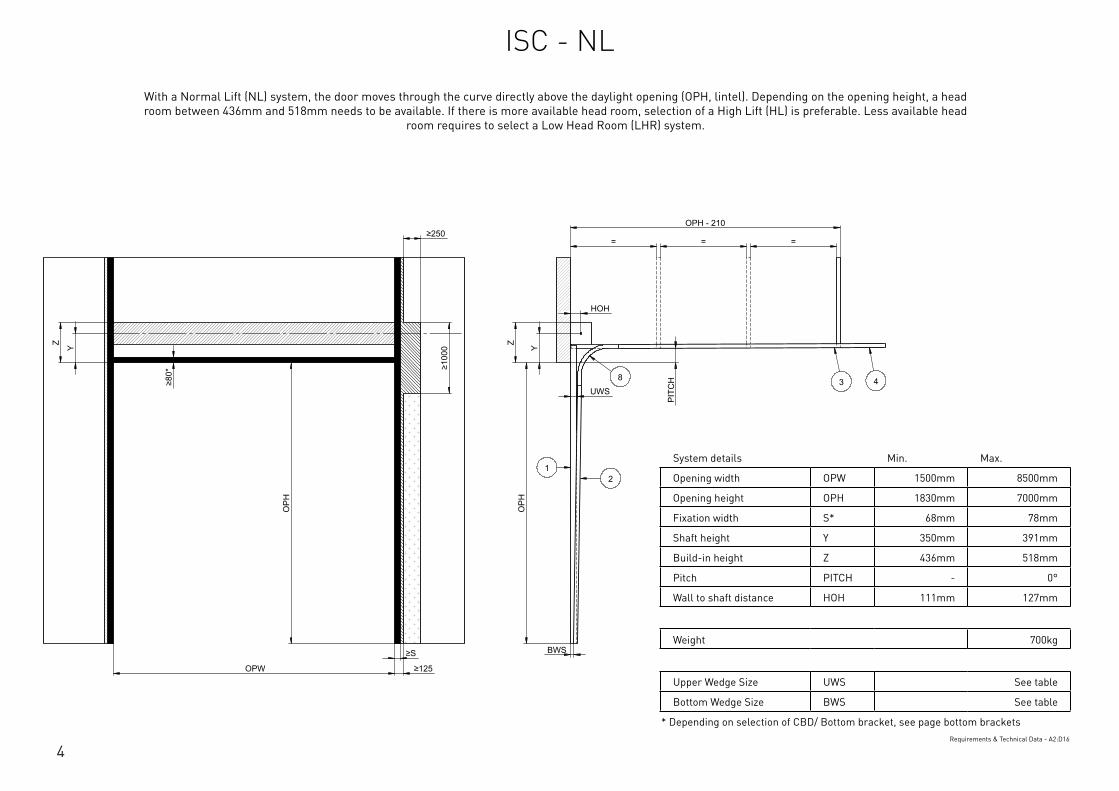
System details Min. Max.
Opening width OPW 1500mm 8500mm
Opening height OPH 1830mm 7000mm
Fixation width S* 68mm 78mm
Shaft height Y 350mm 391mm
Build-in height Z 436mm 518mm
Pitch PITCH - 0°
Wall to shaft distance HOH 111mm 127mm
Weight 700kg
Upper Wedge Size UWS See table
Bottom Wedge Size BWS See table
* Depending on selection of CBD/ Bottom bracket, see page bottom bracketsRequirements & Technical Data - A2:D16
OPH
UWS
HOH
Y
BWS
Z
PIT
CH
OPH
OPW
≥S
≥125
≥10
00
≥80
*
Y Z
OPH - 210
= = = ≥250
12
3 48
This
wor
k is
cop
yrig
ht a
nd n
o pa
rt m
ay b
e re
prod
uced
, by
any
proc
ess,
nor
may
any
oth
er e
xclu
sive
righ
t be
exer
cise
d w
ithou
t the
per
mis
sion
of A
SSA
ABLO
Y.
Surface treatment:
V9_2
019_
02_2
1_dr
wRev.:Document ID
Material: General tolerance:
Volume: Mass: Surface area: Created (YYYY-MM-DD): Designed by: Drawn by: Scale: Projection:
Alternate ID289465723.43 mm³ 1:100 (A3)54462775.75 mm²289465.72 gram
ISO 8015ISO 2768-mH
1SHEET 1 OF 1Configuration:ISC-NL
With a Normal Lift (NL) system, the door moves through the curve directly above the daylight opening (OPH, lintel). Depending on the opening height, a head room between 436mm and 518mm needs to be available. If there is more available head room, selection of a High Lift (HL) is preferable. Less available head
room requires to select a Low Head Room (LHR) system.
ISC - NL
5
System details Min. Max.
Opening width OPW 1500mm 8500mm
Opening height OPH 1830mm 7000mm
Fixation width S* 68mm 78mm
Shaft height Y 350mm 391mm
Build-in height Z 436mm 518mm
Pitch PITCH - 0°
Wall to shaft distance HOH 111mm 127mm
Weight 700kg
Upper Wedge Size UWS See table
Bottom Wedge Size BWS See table
* Depending on selection of CBD/ Bottom bracket, see page bottom bracketsRequirements & Technical Data - A2:D16
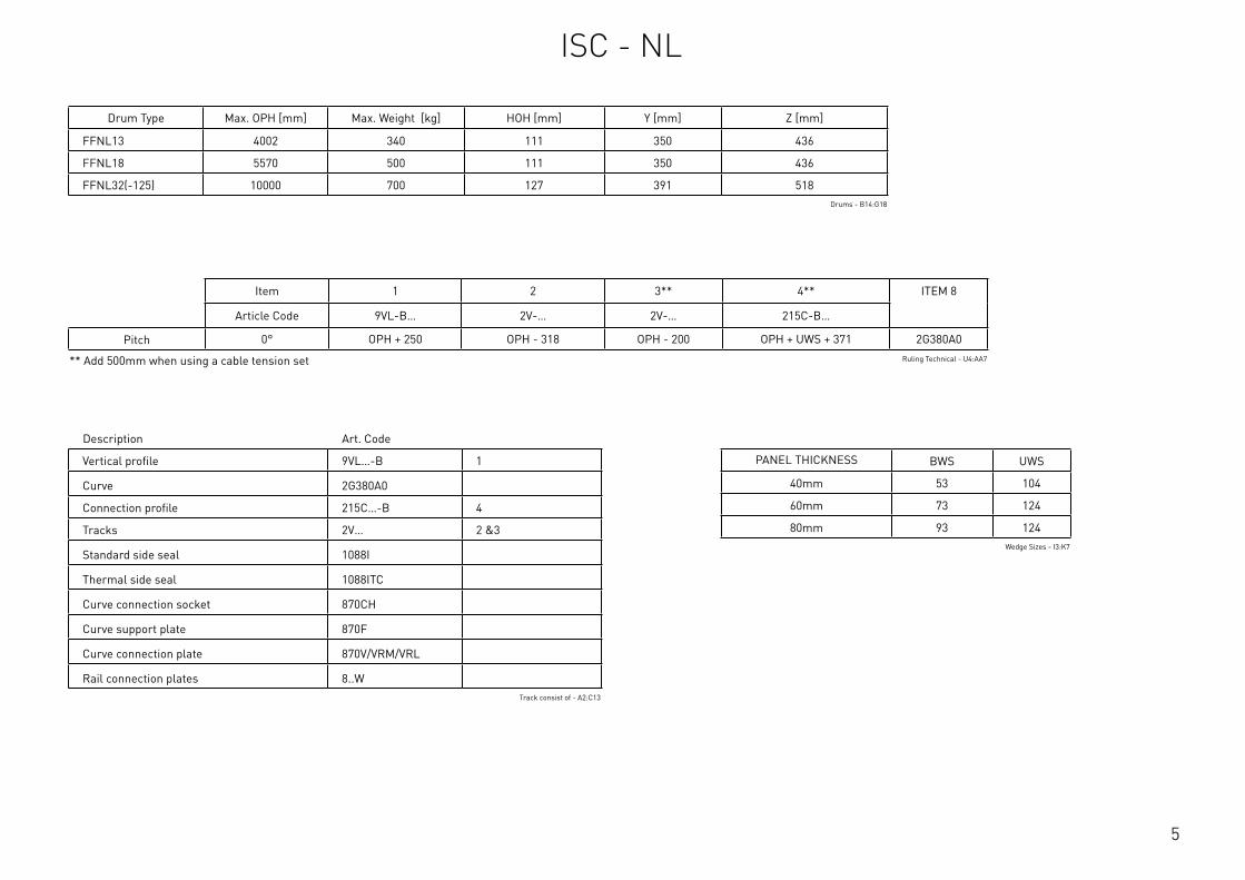
Description Art. Code
Vertical profile 9VL…-B 1
Curve 2G380A0
Connection profile 215C…-B 4
Tracks 2V… 2 &3
Standard side seal 1088I
Thermal side seal 1088ITC
Curve connection socket 870CH
Curve support plate 870F
Curve connection plate 870V/VRM/VRL
Rail connection plates 8..WTrack consist of - A2:C13
Drum Type Max. OPH [mm] Max. Weight [kg] HOH [mm] Y [mm] Z [mm]
FFNL13 4002 340 111 350 436
FFNL18 5570 500 111 350 436
FFNL32(-125) 10000 700 127 391 518Drums - B14:G18
Item 1 2 3** 4** ITEM 8
Article Code 9VL-B… 2V-… 2V-… 215C-B…
Pitch 0° OPH + 250 OPH - 318 OPH - 200 OPH + UWS + 371 2G380A0
** Add 500mm when using a cable tension set Ruling Technical - U4:AA7
PANEL THICKNESS BWS UWS
40mm 53 104
60mm 73 124
80mm 93 124Wedge Sizes - I3:K7
ISC - NL
6
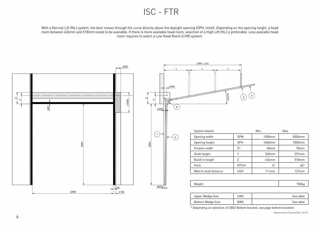
System details Min. Max.
Opening width OPW 1500mm 8500mm
Opening height OPH 1830mm 7000mm
Fixation width S* 68mm 78mm
Shaft height Y 350mm 391mm
Build-in height Z 436mm 518mm
Pitch PITCH 5° 45°
Wall to shaft distance HOH 111mm 127mm
Weight 700kg
Upper Wedge Size UWS See table
Bottom Wedge Size BWS See table
* Depending on selection of CBD/ Bottom bracket, see page bottom bracketsRequirements & Technical Data - G2:J16
OPH
UWS
HOH
Y
BWS
Z
PITCH
OPH
OPW
≥S
≥125
≥10
00
≥80
*
Y Z
OPH - 210
= = = ≥250
12
3 4
8
This
wor
k is
cop
yrig
ht a
nd n
o pa
rt m
ay b
e re
prod
uced
, by
any
proc
ess,
nor
may
any
oth
er e
xclu
sive
righ
t be
exer
cise
d w
ithou
t the
per
mis
sion
of A
SSA
ABLO
Y.
Surface treatment:
V9_2
019_
02_2
1_dr
wRev.:Document ID
Material: General tolerance:
Volume: Mass: Surface area: Created (YYYY-MM-DD): Designed by: Drawn by: Scale: Projection:
Alternate ID289310826.07 mm³ 1:100 (A3)54414606.92 mm²289310.83 gram
ISO 8015ISO 2768-mH
1SHEET 1 OF 1Configuration:ISC-FTR
With a Normal Lift (NL) system, the door moves through the curve directly above the daylight opening (OPH, lintel). Depending on the opening height, a head room between 436mm and 518mm needs to be available. If there is more available head room, selection of a High Lift (HL) is preferable. Less available head
room requires to select a Low Head Room (LHR) system.
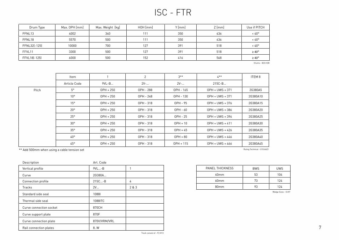
ISC - FTR
7
Description Art. Code
Vertical profile 9VL…-B 1
Curve 2G380A…
Connection profile 215C…-B 4
Tracks 2V… 2 & 3
Standard side seal 1088I
Thermal side seal 1088ITC
Curve connection socket 870CH
Curve support plate 870F
Curve connection plate 870V/VRM/VRL
Rail connection plates 8..WTrack consist of - F2:H13
Drum Type Max. OPH [mm] Max. Weight [kg] HOH [mm] Y [mm] Z [mm] Use if PITCH
FFNL13 4002 340 111 350 436 < 40°
FFNL18 5570 500 111 350 436 < 40°
FFNL32(-125) 10000 700 127 391 518 < 40°
FFVL11 3300 500 127 391 518 ≥ 40°
FFVL18(-125) 6000 500 152 416 568 ≥ 40°Drums - B22:H28
Item 1 2 3** 4** ITEM 8
Article Code 9VL-B… 2V-… 2V-… 215C-B…
Pitch 5° OPH + 250 OPH - 288 OPH - 165 OPH + UWS + 371 2G380A5
10° OPH + 250 OPH - 248 OPH - 130 OPH + UWS + 371 2G380A10
15° OPH + 250 OPH - 318 OPH - 95 OPH + UWS + 376 2G380A15
20° OPH + 250 OPH - 318 OPH - 60 OPH + UWS + 386 2G380A20
25° OPH + 250 OPH - 318 OPH - 25 OPH + UWS + 396 2G380A25
30° OPH + 250 OPH - 318 OPH + 10 OPH + UWS + 411 2G380A30
35° OPH + 250 OPH - 318 OPH + 45 OPH + UWS + 426 2G380A35
40° OPH + 250 OPH - 318 OPH + 80 OPH + UWS + 446 2G380A40
45° OPH + 250 OPH - 318 OPH + 115 OPH + UWS + 466 2G380A45
** Add 500mm when using a cable tension set Ruling Technical - U10:AA21
PANEL THICKNESS BWS UWS
40mm 53 104
60mm 73 124
80mm 93 124Wedge Sizes - I3:K7
ISC - FTR

8
System details Min. Max.
Opening width OPW 1500mm 8500mm
Opening height OPH 1830mm 7000mm
High lift HL 210mm 3010m
Fixation width S* 68mm 78mm
Shaft height HL + Y - HL + 181mm
Build-in height HL + Z - HL + 308mm
Pitch PITCH - 0°
Wall to shaft distance HOH - 127mm
Weight 500kg
Upper Wedge Size UWS See table
Bottom Wedge Size BWS See table
* Depending on selection of CBD/ Bottom bracket, see page bottom bracketsRequirements & Technical Data - A20:D35
OPH
UWS
HOH
BWS
PIT
CH
OPH
OPW
≥S
≥125
≥10
00
≥80
*
HL
+ Y
HL
+ Z
OPH - HL
= = =
HL
Y
Z
≥250
HL
+ Y
HL
+ Z
12
3 48
This
wor
k is
cop
yrig
ht a
nd n
o pa
rt m
ay b
e re
prod
uced
, by
any
proc
ess,
nor
may
any
oth
er e
xclu
sive
righ
t be
exer
cise
d w
ithou
t the
per
mis
sion
of A
SSA
ABLO
Y.
Surface treatment:
V9_2
019_
02_2
1_dr
wRev.:Document ID
Material: General tolerance:
Volume: Mass: Surface area: Created (YYYY-MM-DD): Designed by: Drawn by: Scale: Projection:
Alternate ID415397163.98 mm³ 1:100 (A3)74737484.21 mm²415397.16 gram
ISO 8015ISO 2768-mH
1SHEET 1 OF 1Configuration:ISC-HL-1Piece
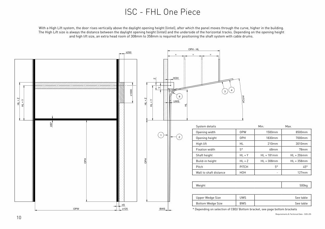
With a High Lift system, the door rises vertically above the daylight opening height (lintel), after which the panel moves through the curve, higher in the building. The High Lift size is always the distance between the daylight opening height (lintel) and the underside of the horizontal tracks. Depending on the opening height and high lift size, an extra head
room of 308mm to 358mm is required for positioning the shaft system with cable drums.
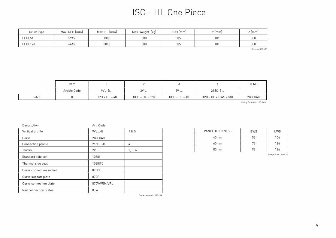
ISC - HL One Piece
9
Description Art. Code
Vertical profile 9VL…-B 1 & 5
Curve 2G380A0
Connection profile 215C…-B 4
Tracks 2V… 2, 3, 6
Standard side seal 1088I
Thermal side seal 1088ITC
Curve connection socket 870CH
Curve support plate 870F
Curve connection plate 870V/VRM/VRL
Rail connection plates 8..WTrack consist of - A17:C28
Drum Type Max. OPH [mm] Max. HL [mm] Max. Weight [kg] HOH [mm] Y [mm] Z [mm]
FFHL54 5945 1380 500 127 181 308
FFHL120 6645 3010 500 127 181 308Drums - B32:H35
Item 1 2 3 4 ITEM 8
Article Code 9VL-B… 2V-… 2V-… 215C-B…
Pitch 0 OPH + HL + 40 OPH + HL - 528 OPH - HL + 10 OPH - HL + UWS + 581 2G380A0Ruling Technical - U25:AA28
PANEL THICKNESS BWS UWS
40mm 53 104
60mm 73 124
80mm 93 124Wedge Sizes - I10:K14
ISC - HL One Piece
10
System details Min. Max.
Opening width OPW 1500mm 8500mm
Opening height OPH 1830mm 7000mm
High lift HL 210mm 3010mm
Fixation width S* 68mm 78mm
Shaft height HL + Y HL + 181mm HL + 206mm
Build-in height HL + Z HL + 308mm HL + 358mm
Pitch PITCH 5° 45°
Wall to shaft distance HOH - 127mm
Weight 500kg
Upper Wedge Size UWS See table
Bottom Wedge Size BWS See table
* Depending on selection of CBD/ Bottom bracket, see page bottom bracketsRequirements & Technical Data - G20:J35
OPH
UWS
HOH
HL
+ Y
BWS
HL
+ Z
PITCH
O
PH
OPW ≥S ≥125
≥10
00
≥80
*
HL
+ Y
HL
+ Z
OPH - HL
= = =
HL
Z
Y
≥250
12
3 4
8
This
wor
k is
cop
yrig
ht a
nd n
o pa
rt m
ay b
e re
prod
uced
, by
any
proc
ess,
nor
may
any
oth
er e
xclu
sive
righ
t be
exer
cise
d w
ithou
t the
per
mis
sion
of A
SSA
ABLO
Y.
Surface treatment:
V9_2
019_
02_2
1_dr
wRev.:Document ID
Material: General tolerance:
Volume: Mass: Surface area: Created (YYYY-MM-DD): Designed by: Drawn by: Scale: Projection:
Alternate ID415364243.14 mm³ 1:100 (A3)74721651.39 mm²415364.24 gram
ISO 8015ISO 2768-mH
1SHEET 1 OF 1Configuration:ISC-FHL-1Piece
With a High Lift system, the door rises vertically above the daylight opening height (lintel), after which the panel moves through the curve, higher in the building. The High Lift size is always the distance between the daylight opening height (lintel) and the underside of the horizontal tracks. Depending on the opening height
and high lift size, an extra head room of 308mm to 358mm is required for positioning the shaft system with cable drums.
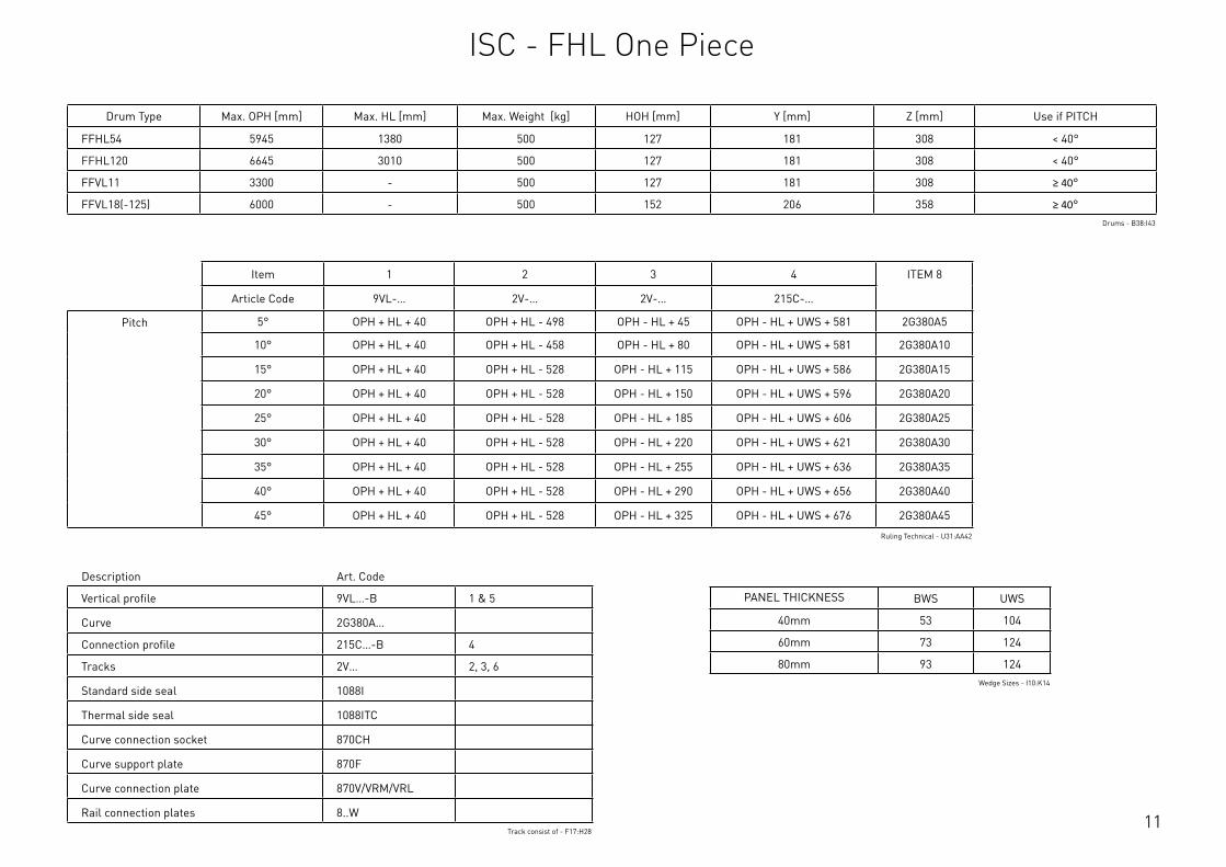
ISC - FHL One Piece
11
Description Art. Code
Vertical profile 9VL…-B 1 & 5
Curve 2G380A…
Connection profile 215C…-B 4
Tracks 2V… 2, 3, 6
Standard side seal 1088I
Thermal side seal 1088ITC
Curve connection socket 870CH
Curve support plate 870F
Curve connection plate 870V/VRM/VRL
Rail connection plates 8..WTrack consist of - F17:H28
Drum Type Max. OPH [mm] Max. HL [mm] Max. Weight [kg] HOH [mm] Y [mm] Z [mm] Use if PITCH
FFHL54 5945 1380 500 127 181 308 < 40°
FFHL120 6645 3010 500 127 181 308 < 40°
FFVL11 3300 - 500 127 181 308 ≥ 40°
FFVL18(-125) 6000 - 500 152 206 358 ≥ 40°Drums - B38:I43
Item 1 2 3 4 ITEM 8
Article Code 9VL-… 2V-… 2V-… 215C-…
Pitch 5° OPH + HL + 40 OPH + HL - 498 OPH - HL + 45 OPH - HL + UWS + 581 2G380A5
10° OPH + HL + 40 OPH + HL - 458 OPH - HL + 80 OPH - HL + UWS + 581 2G380A10
15° OPH + HL + 40 OPH + HL - 528 OPH - HL + 115 OPH - HL + UWS + 586 2G380A15
20° OPH + HL + 40 OPH + HL - 528 OPH - HL + 150 OPH - HL + UWS + 596 2G380A20
25° OPH + HL + 40 OPH + HL - 528 OPH - HL + 185 OPH - HL + UWS + 606 2G380A25
30° OPH + HL + 40 OPH + HL - 528 OPH - HL + 220 OPH - HL + UWS + 621 2G380A30
35° OPH + HL + 40 OPH + HL - 528 OPH - HL + 255 OPH - HL + UWS + 636 2G380A35
40° OPH + HL + 40 OPH + HL - 528 OPH - HL + 290 OPH - HL + UWS + 656 2G380A40
45° OPH + HL + 40 OPH + HL - 528 OPH - HL + 325 OPH - HL + UWS + 676 2G380A45
Ruling Technical - U31:AA42
PANEL THICKNESS BWS UWS
40mm 53 104
60mm 73 124
80mm 93 124Wedge Sizes - I10:K14
ISC - FHL One Piece
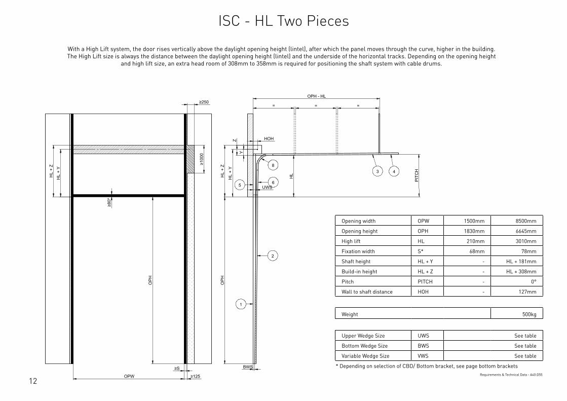
12
Opening width OPW 1500mm 8500mm
Opening height OPH 1830mm 6645mm
High lift HL 210mm 3010mm
Fixation width S* 68mm 78mm
Shaft height HL + Y - HL + 181mm
Build-in height HL + Z - HL + 308mm
Pitch PITCH - 0°
Wall to shaft distance HOH - 127mm
Weight 500kg
Upper Wedge Size UWS See table
Bottom Wedge Size BWS See table
Variable Wedge Size VWS See table
* Depending on selection of CBD/ Bottom bracket, see page bottom bracketsRequirements & Technical Data - A40:D55
OPH
UWS
HOH
HL
+ Y
BWS
HL
+ Z
PIT
CH
OPH
OPW
≥S
≥125
≥10
00
≥80
*
HL
+ Y
HL
+ Z
OPH - HL
= = =
HL
Y
Z
≥250
2
3 48
1
65
This
wor
k is
cop
yrig
ht a
nd n
o pa
rt m
ay b
e re
prod
uced
, by
any
proc
ess,
nor
may
any
oth
er e
xclu
sive
righ
t be
exer
cise
d w
ithou
t the
per
mis
sion
of A
SSA
ABLO
Y.
Surface treatment:
V9_2
019_
02_2
1_dr
wRev.:Document ID
Material: General tolerance:
Volume: Mass: Surface area: Created (YYYY-MM-DD): Designed by: Drawn by: Scale: Projection:
Alternate ID488235193.04 mm³ 1:100 (A3)89835498.33 mm²488235.19 gram
ISO 8015ISO 2768-mH
1SHEET 1 OF 1Configuration:ISC-HL-2Piece
With a High Lift system, the door rises vertically above the daylight opening height (lintel), after which the panel moves through the curve, higher in the building. The High Lift size is always the distance between the daylight opening height (lintel) and the underside of the horizontal tracks. Depending on the opening height
and high lift size, an extra head room of 308mm to 358mm is required for positioning the shaft system with cable drums.
ISC - HL Two Pieces
13
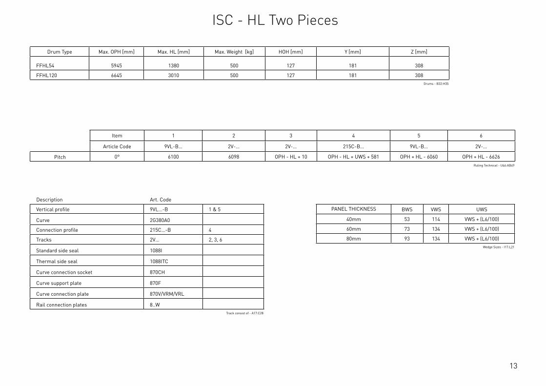
Description Art. Code
Vertical profile 9VL…-B 1 & 5
Curve 2G380A0
Connection profile 215C…-B 4
Tracks 2V… 2, 3, 6
Standard side seal 1088I
Thermal side seal 1088ITC
Curve connection socket 870CH
Curve support plate 870F
Curve connection plate 870V/VRM/VRL
Rail connection plates 8..WTrack consist of - A17:C28
Drum Type Max. OPH [mm] Max. HL [mm] Max. Weight [kg] HOH [mm] Y [mm] Z [mm]
FFHL54 5945 1380 500 127 181 308
FFHL120 6645 3010 500 127 181 308Drums - B32:H35
Item 1 2 3 4 5 6
Article Code 9VL-B… 2V-… 2V-… 215C-B… 9VL-B… 2V-…
Pitch 0° 6100 6098 OPH - HL + 10 OPH - HL + UWS + 581 OPH + HL - 6060 OPH + HL - 6626Ruling Technical - U46:AB49
PANEL THICKNESS BWS VWS UWS
40mm 53 114 VWS + (L6/100)
60mm 73 134 VWS + (L6/100)
80mm 93 134 VWS + (L6/100)Wedge Sizes - I17:L21
ISC - HL Two Pieces

14
System details Min. Max.
Opening width OPW 1500mm 8500mm
Opening height OPH 1830mm 6645mm
High lift HL 210mm 3010mm
Fixation width S* 68mm 78mm
Shaft height HL + Y HL + 181mm HL + 206mm
Build-in height HL + Z HL + 308mm HL + 358mm
Pitch PITCH 5° 45°
Wall to shaft distance HOH - 127mm
Weight 500kg
Upper Wedge Size UWS See table
Bottom Wedge Size BWS See table
Variable Wedge Size VWS See table
* Depending on selection of CBD/ Bottom bracket, see page bottom bracketsRequirements & Technical Data - G39:J55
OPH
UWS
HOH
HL
+ Y
BWS
HL
+ Z
PITCH
O
PH
OPW
≥S
≥125
≥10
00
≥80
*
HL
+ Y
HL
+ Z
OPH - HL
= = =
HL
VWS
Z
Y
≥250
2
34
8
1
65
This
wor
k is
cop
yrig
ht a
nd n
o pa
rt m
ay b
e re
prod
uced
, by
any
proc
ess,
nor
may
any
oth
er e
xclu
sive
righ
t be
exer
cise
d w
ithou
t the
per
mis
sion
of A
SSA
ABLO
Y.
Surface treatment:
V9_2
019_
02_2
1_dr
wRev.:Document ID
Material: General tolerance:
Volume: Mass: Surface area: Created (YYYY-MM-DD): Designed by: Drawn by: Scale: Projection:
Alternate ID488036705.35 mm³ 1:100 (A3)89774518.55 mm²488036.71 gram
ISO 8015ISO 2768-mH
1SHEET 1 OF 1Configuration:ISC-FHL-2Piece
With a High Lift system, the door rises vertically above the daylight opening height (lintel), after which the panel moves through the curve, higher in the building. The High Lift size is always the distance between the daylight opening height (lintel) and the underside of the horizontal tracks. Depending on the opening height
and high lift size, an extra head room of 308mm to 358mm is required for positioning the shaft system with cable drums.
ISC - FHL Two Pieces
15
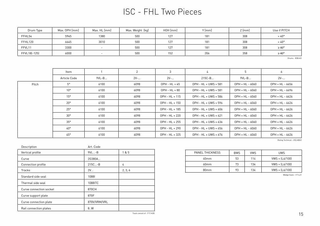
Description Art. Code
Vertical profile 9VL…-B 1 & 5
Curve 2G380A…
Connection profile 215C…-B 4
Tracks 2V… 2, 3, 6
Standard side seal 1088I
Thermal side seal 1088ITC
Curve connection socket 870CH
Curve support plate 870F
Curve connection plate 870V/VRM/VRL
Rail connection plates 8..WTrack consist of - F17:H28
Drum Type Max. OPH [mm] Max. HL [mm] Max. Weight [kg] HOH [mm] Y [mm] Z [mm] Use if PITCH
FFHL54 5945 1380 500 127 181 308 < 40°
FFHL120 6645 3010 500 127 181 308 < 40°
FFVL11 3300 - 500 127 181 308 ≥ 40°
FFVL18(-125) 6000 - 500 152 206 358 ≥ 40°Drums - B38:I43
Item 1 2 3 4 5 6
Article Code 9VL-B… 2V-… 2V-… 215C-B… 9VL-B… 2V-…
Pitch 5° 6100 6098 OPH - HL + 45 OPH - HL + UWS + 581 OPH + HL - 6060 OPH + HL - 6656
10° 6100 6098 OPH - HL + 80 OPH - HL + UWS + 581 OPH + HL - 6060 OPH + HL - 6696
15° 6100 6098 OPH - HL + 115 OPH - HL + UWS + 586 OPH + HL - 6060 OPH + HL - 6626
20° 6100 6098 OPH - HL + 150 OPH - HL + UWS + 596 OPH + HL - 6060 OPH + HL - 6626
25° 6100 6098 OPH - HL + 185 OPH - HL + UWS + 606 OPH + HL - 6060 OPH + HL - 6626
30° 6100 6098 OPH - HL + 220 OPH - HL + UWS + 621 OPH + HL - 6060 OPH + HL - 6626
35° 6100 6098 OPH - HL + 255 OPH - HL + UWS + 636 OPH + HL - 6060 OPH + HL - 6626
40° 6100 6098 OPH - HL + 290 OPH - HL + UWS + 656 OPH + HL - 6060 OPH + HL - 6626
45° 6100 6098 OPH - HL + 325 OPH - HL + UWS + 676 OPH + HL - 6060 OPH + HL - 6626
Ruling Technical - U52:AB63
PANEL THICKNESS BWS VWS UWS
40mm 53 114 VWS + (L6/100)
60mm 73 134 VWS + (L6/100)
80mm 93 134 VWS + (L6/100)Wedge Sizes - I17:L21
ISC - FHL Two Pieces
16
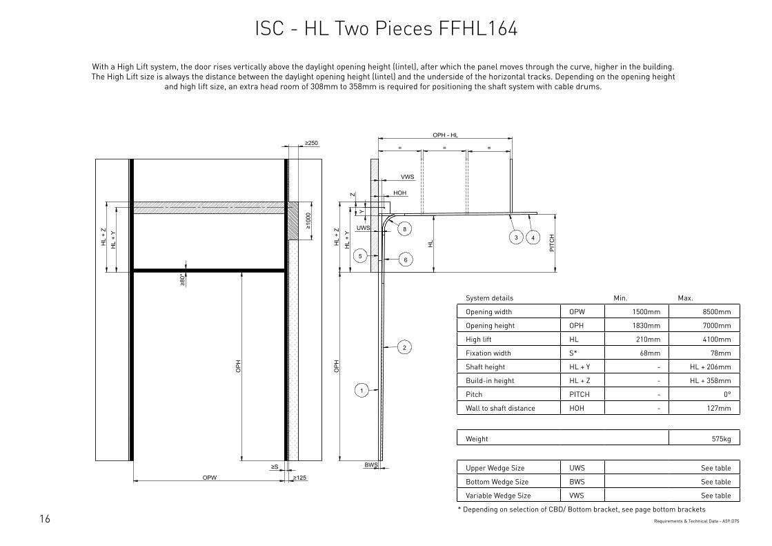
System details Min. Max.
Opening width OPW 1500mm 8500mm
Opening height OPH 1830mm 7000mm
High lift HL 210mm 4100mm
Fixation width S* 68mm 78mm
Shaft height HL + Y - HL + 206mm
Build-in height HL + Z - HL + 358mm
Pitch PITCH - 0°
Wall to shaft distance HOH - 127mm
Weight 575kg
Upper Wedge Size UWS See table
Bottom Wedge Size BWS See table
Variable Wedge Size VWS See table
* Depending on selection of CBD/ Bottom bracket, see page bottom bracketsRequirements & Technical Data - A59:D75
OPH
UWS
HOH
HL
+ Y
BWS
HL
+ Z
PIT
CH
OPH
OPW
≥S
≥125
≥10
00
≥80
*
HL
+ Y
HL
+ Z
OPH - HL
= = =
HL
VWS
Y
Z
≥250
2
3 48
1
65
This
wor
k is
cop
yrig
ht a
nd n
o pa
rt m
ay b
e re
prod
uced
, by
any
proc
ess,
nor
may
any
oth
er e
xclu
sive
righ
t be
exer
cise
d w
ithou
t the
per
mis
sion
of A
SSA
ABLO
Y.
Surface treatment:
V9_2
019_
02_2
1_dr
wRev.:Document ID
Material: General tolerance:
Volume: Mass: Surface area: Created (YYYY-MM-DD): Designed by: Drawn by: Scale: Projection:
Alternate ID450571832.56 mm³ 1:100 (A3)82034869.87 mm²450571.83 gram
ISO 8015ISO 2768-mH
1SHEET 1 OF 1Configuration:ISC-HL-FFHL164-2Piece
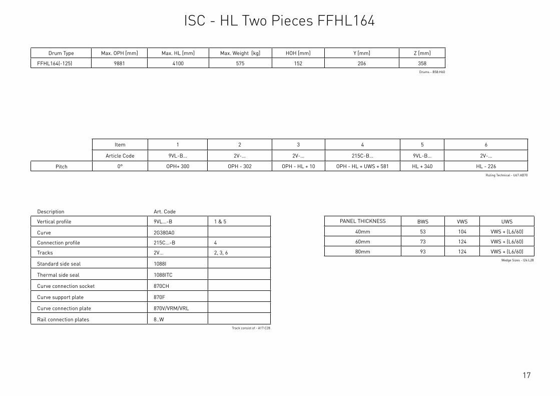
With a High Lift system, the door rises vertically above the daylight opening height (lintel), after which the panel moves through the curve, higher in the building. The High Lift size is always the distance between the daylight opening height (lintel) and the underside of the horizontal tracks. Depending on the opening height
and high lift size, an extra head room of 308mm to 358mm is required for positioning the shaft system with cable drums.
ISC - HL Two Pieces FFHL164
17
Description Art. Code
Vertical profile 9VL…-B 1 & 5
Curve 2G380A0
Connection profile 215C…-B 4
Tracks 2V… 2, 3, 6
Standard side seal 1088I
Thermal side seal 1088ITC
Curve connection socket 870CH
Curve support plate 870F
Curve connection plate 870V/VRM/VRL
Rail connection plates 8..WTrack consist of - A17:C28
Drum Type Max. OPH [mm] Max. HL [mm] Max. Weight [kg] HOH [mm] Y [mm] Z [mm]
FFHL164(-125) 9881 4100 575 152 206 358Drums - B58:H60
Item 1 2 3 4 5 6
Article Code 9VL-B… 2V-… 2V-… 215C-B… 9VL-B… 2V-…
Pitch 0° OPH+ 300 OPH - 302 OPH - HL + 10 OPH - HL + UWS + 581 HL + 340 HL - 226Ruling Technical - U67:AB70
PANEL THICKNESS BWS VWS UWS
40mm 53 104 VWS + (L6/60)
60mm 73 124 VWS + (L6/60)
80mm 93 124 VWS + (L6/60)Wedge Sizes - I24:L28
ISC - HL Two Pieces FFHL164

18
System details Min. Max.
Opening width OPW 1500mm 8500mm
Opening height OPH 1830mm 7000mm
High lift HL 210mm 4100mm
Fixation width S* 68mm 78mm
Shaft height HL + Y - HL + 206mm
Build-in height HL + Z - HL + 358mm
Pitch PITCH 5° 35°
Wall to shaft distance HOH - 127mm
Weight 575kg
Upper Wedge Size UWS See table
Bottom Wedge Size BWS See table
Variable Wedge Size VWS See table
* Depending on selection of CBD/ Bottom bracket, see page bottom bracketsRequirements & Technical Data - G59:J75
OPH
UWS
HOH
HL
+ Y
BWS
HL
+ Z
PITCH
OPH
OPW
≥S
≥125
≥10
00
≥80
*
HL
+ Y
HL
+ Z
OPH - HL
= = =
HL
VWS
Z
Y
≥250
2
3 4
8
1
65
This
wor
k is
cop
yrig
ht a
nd n
o pa
rt m
ay b
e re
prod
uced
, by
any
proc
ess,
nor
may
any
oth
er e
xclu
sive
righ
t be
exer
cise
d w
ithou
t the
per
mis
sion
of A
SSA
ABLO
Y.
Surface treatment:
V9_2
019_
02_2
1_dr
wRev.:Document ID
Material: General tolerance:
Volume: Mass: Surface area: Created (YYYY-MM-DD): Designed by: Drawn by: Scale: Projection:
Alternate ID450101481.54 mm³ 1:100 (A3)81922696.8 mm²450101.48 gram
ISO 8015ISO 2768-mH
1SHEET 1 OF 1Configuration:ISC-FHL-FFHL164-2Piece
With a High Lift system, the door rises vertically above the daylight opening height (lintel), after which the panel moves through the curve, higher in the building. The High Lift size is always the distance between the daylight opening height (lintel) and the underside of the horizontal tracks. Depending on the opening height
and high lift size, an extra head room of 308mm to 358mm is required for positioning the shaft system with cable drums.
ISC - FHL Two Pieces FFHL164

19
Description Art. Code
Vertical profile 9VL…-B 1 & 5
Curve 2G380A…
Connection profile 215C…-B 4
Tracks 2V… 2, 3, 6
Standard side seal 1088I
Thermal side seal 1088ITC
Curve connection socket 870CH
Curve support plate 870F
Curve connection plate 870V/VRM/VRL
Rail connection plates 8..WTrack consist of - F17:H28
Drum Type Max. OPH [mm] Max. HL [mm] Max. Weight [kg] HOH [mm] Y [mm] Z [mm] Use if PITCH
FFHL164(-125) 9881 4100 575 152 206 358 < 40°Drums - B63:I65
Item 1 2 3 4 5 6
Article Code 9VL-B… 2V-… 2V-… 215C-B… 9VL-B… 2V-…
Pitch 5° OPH+ 300 OPH - 302 OPH - HL + 45 OPH - HL + UWS + 581 HL + 340 HL - 196
10° OPH+ 300 OPH - 302 OPH - HL + 80 OPH - HL + UWS + 581 HL + 340 HL - 156
15° OPH+ 300 OPH - 302 OPH - HL + 115 OPH - HL + UWS + 586 HL + 340 HL - 226
20° OPH+ 300 OPH - 302 OPH - HL + 150 OPH - HL + UWS + 596 HL + 340 HL - 226
25° OPH+ 300 OPH - 302 OPH - HL + 185 OPH - HL + UWS + 606 HL + 340 HL - 226
30° OPH+ 300 OPH - 302 OPH - HL + 220 OPH - HL + UWS + 621 HL + 340 HL - 226
35° OPH+ 300 OPH - 302 OPH - HL + 255 OPH - HL + UWS + 636 HL + 340 HL - 226
40° OPH+ 300 OPH - 302 OPH - HL + 290 OPH - HL + UWS + 656 HL + 340 HL - 226
45° OPH+ 300 OPH - 302 OPH - HL + 325 OPH - HL + UWS + 676 HL + 340 HL - 226
Ruling Technical - U73:AB84
PANEL THICKNESS BWS VWS UWS
40mm 53 104 VWS + (L6/60)
60mm 73 124 VWS + (L6/60)
80mm 93 124 VWS + (L6/60)Wedge Sizes - I24:L28
ISC - FHL Two Pieces FFHL164
20
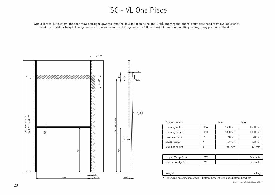
System details Min. Max.
Opening width OPW 1500mm 8500mm
Opening height OPH 1830mm 3300mm
Fixation width S* 68mm 78mm
Shaft height Y 127mm 152mm
Build-in height Z 254mm 304mm
Upper Wedge Size UWS See table
Bottom Wedge Size BWS See table
Weight 500kg
* Depending on selection of CBD/ Bottom bracket, see page bottom bracketsRequirements & Technical Data - A79:D91
OPH
HOH
Y
BWS
Z
OPH
OPW ≥S ≥125
≥80
≥250
≥10
00
UWS
(2 x
OPH
) + 3
00
(2 x
OPH
) + 3
00 +
Y
(2 x
OPH
) + 3
00 +
Z 2
1
This
wor
k is
cop
yrig
ht a
nd n
o pa
rt m
ay b
e re
prod
uced
, by
any
proc
ess,
nor
may
any
oth
er e
xclu
sive
righ
t be
exer
cise
d w
ithou
t the
per
mis
sion
of A
SSA
ABLO
Y.
Surface treatment:
V9_2
019_
02_2
1_dr
wRev.:Document ID
Material: General tolerance:
Volume: Mass: Surface area: Created (YYYY-MM-DD): Designed by: Drawn by: Scale: Projection:
Alternate ID531320092.93 mm³ 1:100 (A3)90915516.55 mm²531320.09 gram
ISO 8015ISO 2768-mH
1SHEET 1 OF 1Configuration:ISC-VL-1Piece
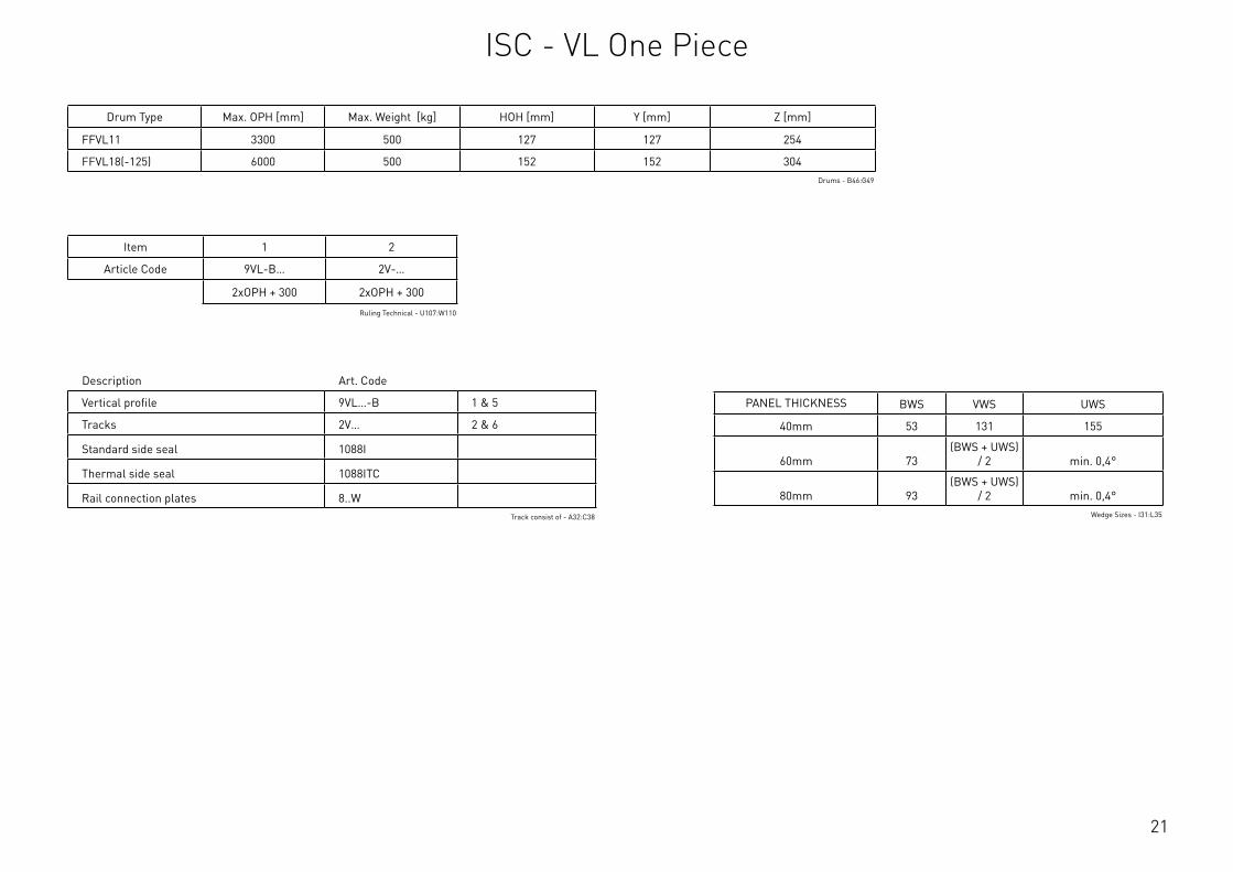
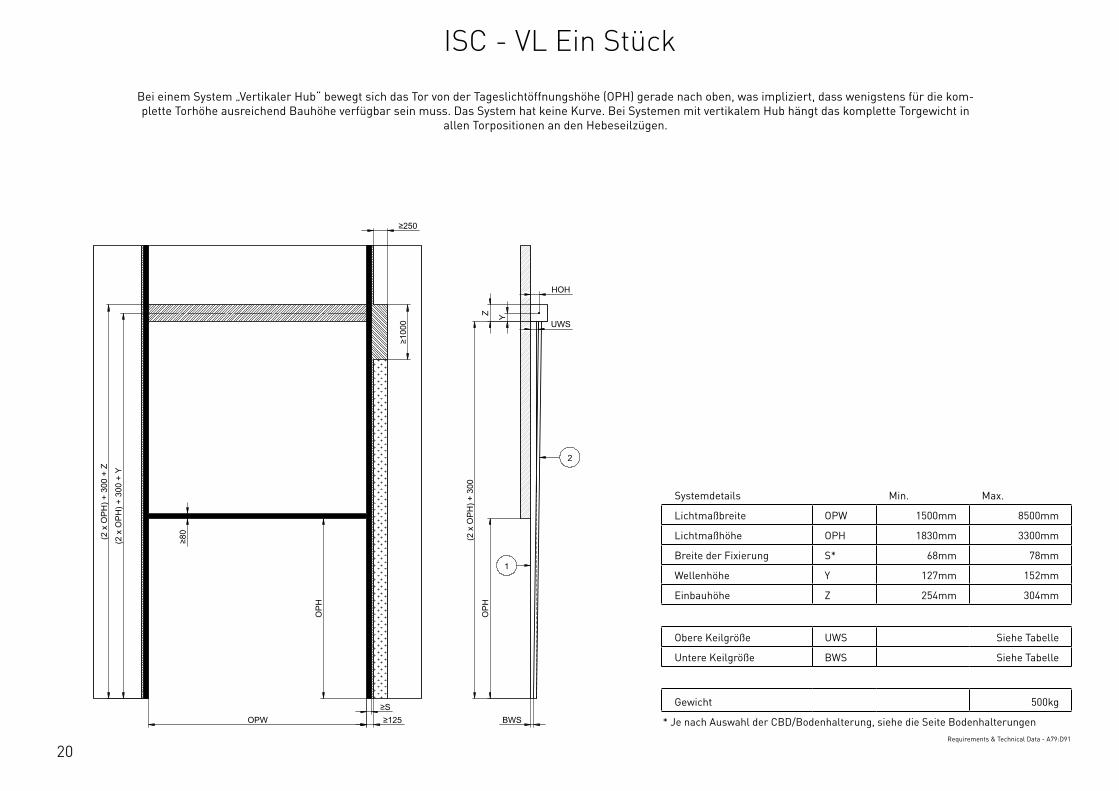
With a Vertical Lift system, the door moves straight upwards from the daylight opening height (OPH), implying that there is sufficient head room available for at least the total door height. The system has no curve. In Vertical Lift systems the full door weight hangs in the lifting cables, in any position of the door
ISC - VL One Piece
21
Description Art. Code
Vertical profile 9VL…-B 1 & 5
Tracks 2V… 2 & 6
Standard side seal 1088I
Thermal side seal 1088ITC
Rail connection plates 8..WTrack consist of - A32:C38
Drum Type Max. OPH [mm] Max. Weight [kg] HOH [mm] Y [mm] Z [mm]
FFVL11 3300 500 127 127 254
FFVL18(-125) 6000 500 152 152 304Drums - B46:G49
Item 1 2
Article Code 9VL-B… 2V-…
2xOPH + 300 2xOPH + 300
Ruling Technical - U107:W110
PANEL THICKNESS BWS VWS UWS
40mm 53 131 155
60mm 73(BWS + UWS)
/ 2 min. 0,4°
80mm 93(BWS + UWS)
/ 2 min. 0,4°Wedge Sizes - I31:L35
ISC - VL One Piece

22
System details Min. Max.
Opening width OPW 1500mm 8500mm
Opening height OPH 1830mm 6000mm
Fixation width S* 68mm 78mm
Shaft height Y - 152mm
Build-in height Z - 304mm
Weight 500kg
* Depending on selection of CBD/ Bottom bracket, see page bottom bracketsRequirements & Technical Data - A95:D104
OPH
HOH
Y
BWS
Z
OPH
OPW ≥S ≥125
≥80
≥250
≥10
00
UWS
VWS (2
x O
PH) +
300
+ Z
(2 x
OPH
) + 3
00 +
Y
(2 x
OPH
) + 3
00 +
Z
2
1
6
5
This
wor
k is
cop
yrig
ht a
nd n
o pa
rt m
ay b
e re
prod
uced
, by
any
proc
ess,
nor
may
any
oth
er e
xclu
sive
righ
t be
exer
cise
d w
ithou
t the
per
mis
sion
of A
SSA
ABLO
Y.
Surface treatment:
V9_2
019_
02_2
1_dr
wRev.:Document ID
Material: General tolerance:
Volume: Mass: Surface area: Created (YYYY-MM-DD): Designed by: Drawn by: Scale: Projection:
Alternate ID552648112.93 mm³ 1:100 (A3)95351980.55 mm²552648.11 gram
ISO 8015ISO 2768-mH
1SHEET 1 OF 1Configuration:ISC-VL-2Piece
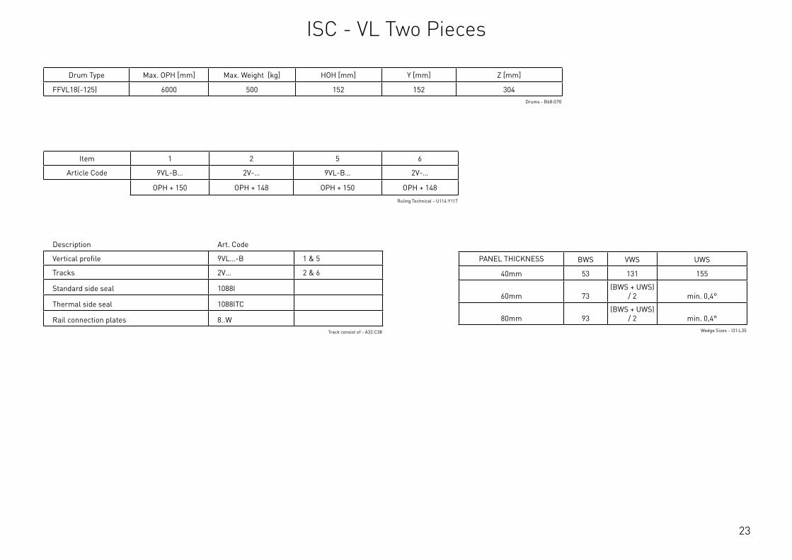
With a Vertical Lift system, the door moves straight upwards from the daylight opening height (OPH), implying that there is sufficient head room available for at least the total door height. The system has no curve. In Vertical Lift systems the full door weight hangs in the lifting cables, in any position of the door
ISC - VL Two Pieces
23
Description Art. Code
Vertical profile 9VL…-B 1 & 5
Tracks 2V… 2 & 6
Standard side seal 1088I
Thermal side seal 1088ITC
Rail connection plates 8..WTrack consist of - A32:C38
Drum Type Max. OPH [mm] Max. Weight [kg] HOH [mm] Y [mm] Z [mm]
FFVL18(-125) 6000 500 152 152 304Drums - B68:G70
Item 1 2 5 6
Article Code 9VL-B… 2V-… 9VL-B… 2V-…
OPH + 150 OPH + 148 OPH + 150 OPH + 148
Ruling Technical - U114:Y117
PANEL THICKNESS BWS VWS UWS
40mm 53 131 155
60mm 73(BWS + UWS)
/ 2 min. 0,4°
80mm 93(BWS + UWS)
/ 2 min. 0,4°Wedge Sizes - I31:L35
ISC - VL Two Pieces
24
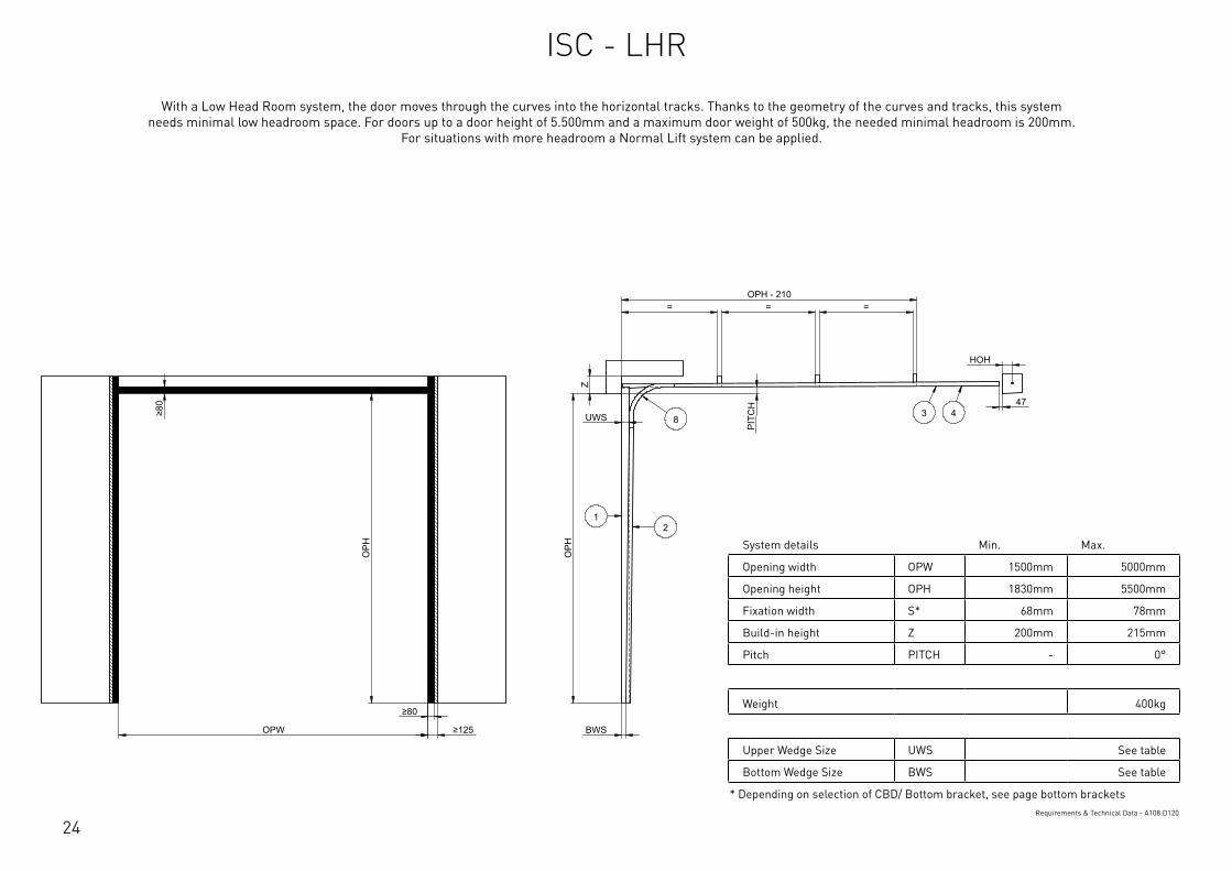
System details Min. Max.
Opening width OPW 1500mm 5000mm
Opening height OPH 1830mm 5500mm
Fixation width S* 68mm 78mm
Build-in height Z 200mm 215mm
Pitch PITCH - 0°
Weight 400kg
Upper Wedge Size UWS See table
Bottom Wedge Size BWS See table
* Depending on selection of CBD/ Bottom bracket, see page bottom bracketsRequirements & Technical Data - A108:D120
OPH
UWS
BWS
PIT
CH
OPW
OPH
≥80
≥80
≥125
HOH
47
= = = OPH - 210
Z
12
3 48
This
wor
k is
cop
yrig
ht a
nd n
o pa
rt m
ay b
e re
prod
uced
, by
any
proc
ess,
nor
may
any
oth
er e
xclu
sive
righ
t be
exer
cise
d w
ithou
t the
per
mis
sion
of A
SSA
ABLO
Y.
Surface treatment:
V9_2
019_
02_2
1_dr
wRev.:Document ID
Material: General tolerance:
Volume: Mass: Surface area: Created (YYYY-MM-DD): Designed by: Drawn by: Scale: Projection:
Alternate ID142976550.27 mm³ 1:100 (A3)25577248.67 mm²142976.55 gram
ISO 8015ISO 2768-mH
1SHEET 1 OF 1Configuration:ISC-LHR
With a Low Head Room system, the door moves through the curves into the horizontal tracks. Thanks to the geometry of the curves and tracks, this system needs minimal low headroom space. For doors up to a door height of 5.500mm and a maximum door weight of 500kg, the needed minimal headroom is 200mm.
For situations with more headroom a Normal Lift system can be applied.
ISC - LHR
25
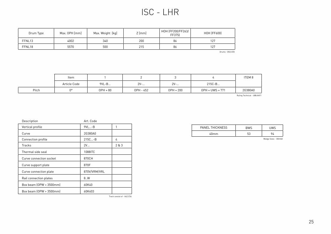
Drum Type Max. OPH [mm] Max. Weight [kg] Z [mm] HOH (FF200/FF263/FF375) HOH (FF600)
FFNL13 4002 340 200 86 127
FFNL18 5570 500 215 86 127Drums - B52:G55
Item 1 2 3 4 ITEM 8
Article Code 9VL-B… 2V-… 2V-… 215C-B…
Pitch 0° OPH + 80 OPH - 452 OPH + 200 OPH + UWS + 771 2G380A0Ruling Technical - U88:AA91
PANEL THICKNESS BWS UWS
40mm 53 94Wedge Sizes - I38:K40
Description Art. Code
Vertical profile 9VL…-B 1
Curve 2G380A0
Connection profile 215C…-B 4
Tracks 2V… 2 & 3
Thermal side seal 1088ITC
Curve connection socket 870CH
Curve support plate 870F
Curve connection plate 870V/VRM/VRL
Rail connection plates 8..W
Box beam (OPW < 3500mm) 60K40
Box beam (OPW > 3500mm) 60K403Track consist of - A42:C54
ISC - LHR
26
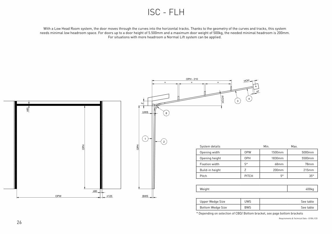
System details Min. Max.
Opening width OPW 1500mm 5000mm
Opening height OPH 1830mm 5500mm
Fixation width S* 68mm 78mm
Build-in height Z 200mm 215mm
Pitch PITCH 5° 35°
Weight 400kg
Upper Wedge Size UWS See table
Bottom Wedge Size BWS See table
* Depending on selection of CBD/ Bottom bracket, see page bottom bracketsRequirements & Technical Data - G108:J120
OPH
UWS
BWS
PITCH
OPW
OPH
≥80
≥80
≥125
HOH
47
= = = OPH - 210
Z
12
34
8
This
wor
k is
cop
yrig
ht a
nd n
o pa
rt m
ay b
e re
prod
uced
, by
any
proc
ess,
nor
may
any
oth
er e
xclu
sive
righ
t be
exer
cise
d w
ithou
t the
per
mis
sion
of A
SSA
ABLO
Y.
Surface treatment:
V9_2
019_
02_2
1_dr
wRev.:Document ID
Material: General tolerance:
Volume: Mass: Surface area: Created (YYYY-MM-DD): Designed by: Drawn by: Scale: Projection:
Alternate ID142758386.18 mm³ 1:100 (A3)25601845.72 mm²142758.39 gram
ISO 8015ISO 2768-mH
1SHEET 1 OF 1Configuration:ISC-FHR
With a Low Head Room system, the door moves through the curves into the horizontal tracks. Thanks to the geometry of the curves and tracks, this system needs minimal low headroom space. For doors up to a door height of 5.500mm and a maximum door weight of 500kg, the needed minimal headroom is 200mm.
For situations with more headroom a Normal Lift system can be applied.
ISC - FLH

27
Drum Type Max. OPH [mm] Max. Weight [kg] Z [mm] HOH (FF200/FF263/FF375) HOH (FF600)
FFNL13 4002 340 200 86 127
FFNL18 5570 500 215 86 127Drums - B52:G55
Item 1 2 3 4 ITEM 8
Article Code 9VL-B… 2V-… 2V-… 215C-B…
Pitch 10° OPH + 80 OPH - 452 OPH + 270 OPH + UWS + 771 2G380A10
15° OPH + 80 OPH - 422 OPH + 305 OPH + UWS + 776 2G380A15
20° OPH + 80 OPH - 382 OPH + 340 OPH + UWS + 786 2G380A20
25° OPH + 80 OPH - 382 OPH + 375 OPH + UWS + 796 2G380A25
30° OPH + 80 OPH - 360 OPH + 410 OPH + UWS + 811 2G380A30
35° OPH + 80 OPH - 352 OPH + 445 OPH + UWS + 826 2G380A35
Ruling Technical - U95:AA103
PANEL THICKNESS BWS UWS
40mm 53 94Wedge Sizes - I38:K40
Description Art. Code
Vertical profile 9VL…-B 1
Curve 2G380A…
Connection profile 215C…-B 4
Tracks 2V… 2 & 3
Thermal side seal 1088ITC
Curve connection socket 870CH
Curve support plate 870F
Curve connection plate 870V/VRM/VRL
Rail connection plates 8..W
Box beam (OPW < 3500mm) 60K40
Box beam (OPW > 3500mm) 60K403Track consist of - F42:H55
ISC - FLH

28
BOTTOM BRACKET INFORMATION
NL / HL / VL LHR
Side Seal Side Seal
1088I / 1088ITC 1088ITC
Art. Code S [mm] S [mm]Add to achieve play of 5mm bet-
ween track & bracket*
425HD 76 - 2066-10
427SX 68 78 2066-07
428TAI 72 78 -
429 68 78 2066-05
429S 68 78 2066-10
440-REGL 76 78 -
440HD 76 - -
440-600 74 78 -
440S 74 78 -
440 74 78 -
444 78 - -
* The play of 5mm is needed for the required movement of ±5mm
Bottom Brackets - A3:D19
E E
F F
SCALE: GENERALROUGHNESS:
PROJECTION:FORMAT: UNIT:
mmTOLERANCES UNLESS
OTHERWISE STATED Acc. To ISO 2768-cK
MATERIAL
TREATMENT
DESCRIPTION
ARTICLE CODE DRAWING NUMBER REVISION
CREATION DATE NETTO WEIGHTCREATED BY
THICKNESS
FLAT WIDTH
FLAT LENGHT
mm
mm
mm
This drawing is property ofFlexiForce
and contains confidentionalinformation.
All rights are strictly reserved.Reproduction
and use for production purposesissue to
third parties in any form whatsoever,is not permitted without written authority from the proprietors.
36 001 001 A
Position of Vertical Angle based on Side Seal and Bottom Bracket
...
JiGa 9-8-2016 538,183 kg
-
A3-
-
---
-C:\V
aultWor
kspa
ce\R
&D\T
eke n
inge
n\36
\360
0100
1\36
001 0
01\4
40 -
108
8I.ia
m
0.5-3 >3-6 >6-30 >30-120 >120-400 >400-1000 >1000-2000 >2000-4000
:
:
:
: :
: : :
: : :
±0.20 ±0.30 ±0.50 ±0.80 ±1.20 ±2.00 ±3.00 ±4.00
Nomi
nal dime
nsion
:
3
A3 Changed values in table, see excel file JiGa 20-01-2017A2 Changed values in table, see excel file JiGa 10-01-2017REV. DESCRIPTION NAME DATE
Side Seal Side Seal 1088I / 1088IT
Bottom Bracket S [mm]Technical S [mm]CommercialAdd to achieve play of 5mm between track and bracket
425HD 75,5 76 2066-10427SX 67,5 68 2066-07428TAI 72 72 -429 67,5 68 2066-05429S 67,5 68 2066-10440-REGL 75,5 76 -440HD 75,5 76 -440-600 73,5 74 -440S 73,5 74 -440 73,5 74 -444 77,5 78 -
S
22,5
1088I
22,5
S
1088ITAcceptable
The play of 5mm is needed for the required pendel of +5mm/-5mm
29
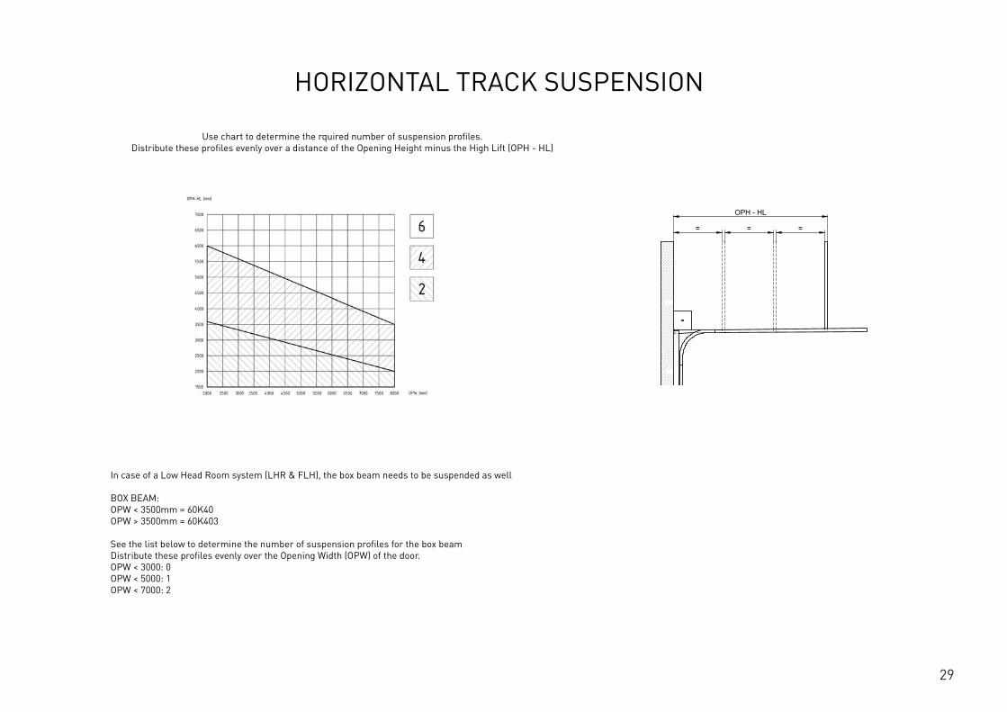
HORIZONTAL TRACK SUSPENSION
Use chart to determine the rquired number of suspension profiles. Distribute these profiles evenly over a distance of the Opening Height minus the High Lift (OPH - HL)
In case of a Low Head Room system (LHR & FLH), the box beam needs to be suspended as well BOX BEAM: OPW < 3500mm = 60K40 OPW > 3500mm = 60K403 See the list below to determine the number of suspension profiles for the box beam Distribute these profiles evenly over the Opening Width (OPW) of the door. OPW < 3000: 0 OPW < 5000: 1 OPW < 7000: 2
OPH
BWS
OPH
OPW
≥S
≥125
≥10
00
≥80
*
HL
+ Y
HL
+ Z
OPH - HL
= = = ≥250
12
This
wor
k is
cop
yrig
ht a
nd n
o pa
rt m
ay b
e re
prod
uced
, by
any
proc
ess,
nor
may
any
oth
er e
xclu
sive
righ
t be
exer
cise
d w
ithou
t the
per
mis
sion
of A
SSA
ABLO
Y.
Surface treatment:
V9_2
019_
02_2
1_dr
wRev.:Document ID
Material: General tolerance:
Volume: Mass: Surface area: Created (YYYY-MM-DD): Designed by: Drawn by: Scale: Projection:
Alternate ID415397163.98 mm³ 1:100 (A3)74737484.21 mm²415397.16 gram
ISO 8015ISO 2768-mH
1SHEET 1 OF 1Configuration:ISC-HL-1Piece

30

31
WHERE TO FIND US
FlexiForce B.V. Hanzeweg 19, 3771 NG Barneveld PO Box 37, 3770 AA Barneveld The Netherlands +31-(0)342-427777 [email protected]
FlexiForce Hungary Kft. Medvefű str. 24 4031 Debrecen Hungary +36-52561260 [email protected]
FlexiForce Ibérica, S.L. Apartado Correos 403 Ctra. Nacional 332, Km. 211 46780 – Oliva (Valencia) Spain +34 96.285.82.50 [email protected]
FlexiForce Poland Sp. z o.o. Norblina 17/19 95-015 Głowno Poland +48 426500491 [email protected]
FlexiForce Italia Srl. Via dei Tigli CNM 25020 Alfianello Italia +39 0309936510 [email protected]
FlexiForce Turkey Marmara Geri Donusumculer Toplu İsyeri Yapı Kooperatifi Sekerpinar Mahallesi Aycicek Sokak Kapi No: 24 (245 ada, 31 parsel) 41420, Çayirova, KOCAELI / TURKEY +90 262 658 2058 [email protected]
www.flexiforce.com

32
HEALTH AND SAFETY AT DOOR INSTALLATIONS!
1
TECHNISCHES HANDBUCHISC INDUSTRIELLES HARDWARE-SYSTEM
DE. 3.1
2
INHALTSVERZEICHNIS
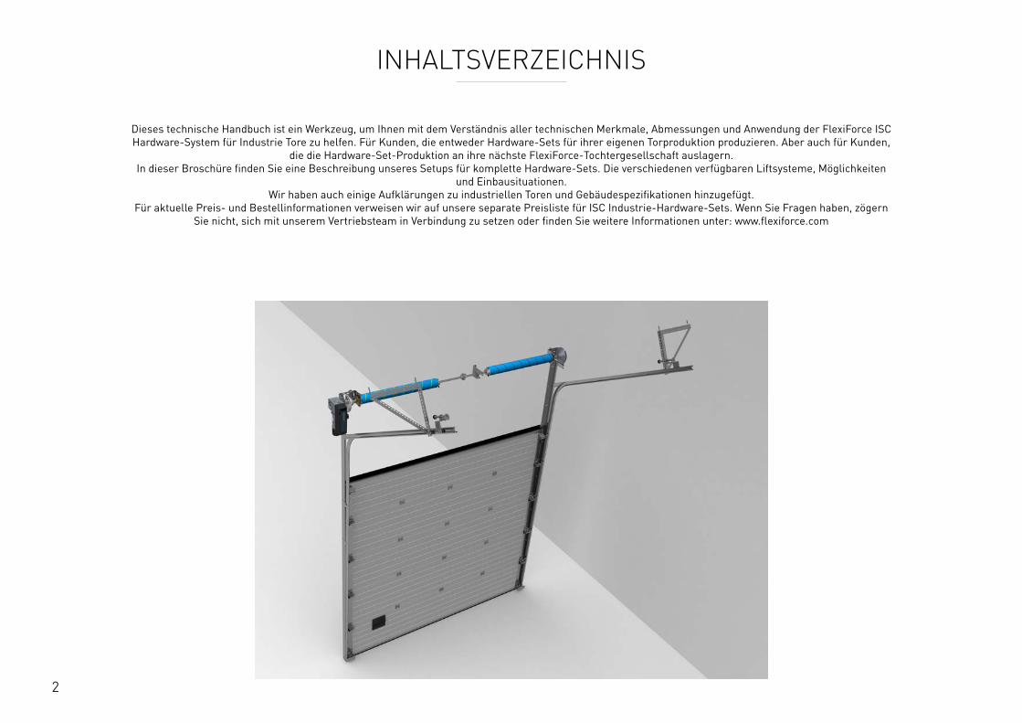
Dieses technische Handbuch ist ein Werkzeug, um Ihnen mit dem Verständnis aller technischen Merkmale, Abmessungen und Anwendung der FlexiForce ISC Hardware-System fur Industrie Tore zu helfen. Fur Kunden, die entweder Hardware-Sets fur ihrer eigenen Torproduktion produzieren. Aber auch fur Kunden,
die die Hardware-Set-Produktion an ihre nächste FlexiForce-Tochtergesellschaft auslagern. In dieser Broschure finden Sie eine Beschreibung unseres Setups fur komplette Hardware-Sets. Die verschiedenen verfugbaren Liftsysteme, Möglichkeiten
und Einbausituationen. Wir haben auch einige Aufklärungen zu industriellen Toren und Gebäudespezifikationen hinzugefugt.
Fur aktuelle Preis- und Bestellinformationen verweisen wir auf unsere separate Preisliste fur ISC Industrie-Hardware-Sets. Wenn Sie Fragen haben, zögern Sie nicht, sich mit unserem Vertriebsteam in Verbindung zu setzen oder finden Sie weitere Informationen unter: www.flexiforce.com
3
INHALTSVERZEICHNIS
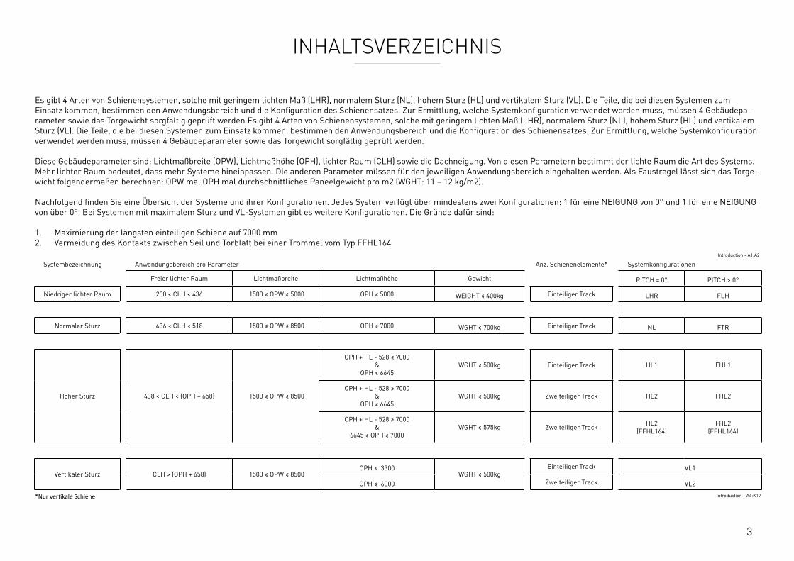
Es gibt 4 Arten von Schienensystemen, solche mit geringem lichten Maß (LHR), normalem Sturz (NL), hohem Sturz (HL) und vertikalem Sturz (VL). Die Teile, die bei diesen Systemen zum Einsatz kommen, bestimmen den Anwendungsbereich und die Konfiguration des Schienensatzes. Zur Ermittlung, welche Systemkonfiguration verwendet werden muss, mussen 4 Gebäudepa-rameter sowie das Torgewicht sorgfältig gepruft werden.Es gibt 4 Arten von Schienensystemen, solche mit geringem lichten Maß (LHR), normalem Sturz (NL), hohem Sturz (HL) und vertikalem Sturz (VL). Die Teile, die bei diesen Systemen zum Einsatz kommen, bestimmen den Anwendungsbereich und die Konfiguration des Schienensatzes. Zur Ermittlung, welche Systemkonfiguration verwendet werden muss, mussen 4 Gebäudeparameter sowie das Torgewicht sorgfältig gepruft werden. Diese Gebäudeparameter sind: Lichtmaßbreite (OPW), Lichtmaßhöhe (OPH), lichter Raum (CLH) sowie die Dachneigung. Von diesen Parametern bestimmt der lichte Raum die Art des Systems. Mehr lichter Raum bedeutet, dass mehr Systeme hineinpassen. Die anderen Parameter mussen fur den jeweiligen Anwendungsbereich eingehalten werden. Als Faustregel lässt sich das Torge-wicht folgendermaßen berechnen: OPW mal OPH mal durchschnittliches Paneelgewicht pro m2 (WGHT: 11 – 12 kg/m2). Nachfolgend finden Sie eine Übersicht der Systeme und ihrer Konfigurationen. Jedes System verfugt uber mindestens zwei Konfigurationen: 1 fur eine NEIGUNG von 0° und 1 fur eine NEIGUNG von uber 0°. Bei Systemen mit maximalem Sturz und VL-Systemen gibt es weitere Konfigurationen. Die Grunde dafur sind: 1. Maximierung der längsten einteiligen Schiene auf 7000 mm 2. Vermeidung des Kontakts zwischen Seil und Torblatt bei einer Trommel vom Typ FFHL164
Introduction - A1:A2
Systembezeichnung Anwendungsbereich pro Parameter Anz. Schienenelemente* Systemkonfigurationen
Freier lichter Raum Lichtmaßbreite Lichtmaßhöhe Gewicht PITCH = 0° PITCH > 0°
Niedriger lichter Raum 200 < CLH < 436 1500 ≤ OPW ≤ 5000 OPH ≤ 5000 WEIGHT ≤ 400kg Einteiliger Track LHR FLH
Normaler Sturz 436 < CLH < 518 1500 ≤ OPW ≤ 8500 OPH ≤ 7000 WGHT ≤ 700kg Einteiliger Track NL FTR
Hoher Sturz 438 < CLH < (OPH + 658) 1500 ≤ OPW ≤ 8500
OPH + HL - 528 ≤ 7000 &
OPH ≤ 6645WGHT ≤ 500kg Einteiliger Track HL1 FHL1
OPH + HL - 528 ≥ 7000 &
OPH ≤ 6645WGHT ≤ 500kg Zweiteiliger Track HL2 FHL2
OPH + HL - 528 ≥ 7000 &
6645 ≤ OPH ≤ 7000WGHT ≤ 575kg Zweiteiliger Track HL2
(FFHL164)FHL2
(FFHL164)
Vertikaler Sturz CLH > (OPH + 658) 1500 ≤ OPW ≤ 8500OPH ≤ 3300
WGHT ≤ 500kgEinteiliger Track VL1
OPH ≤ 6000 Zweiteiliger Track VL2
*Nur vertikale Schiene Introduction - A4:K17
4
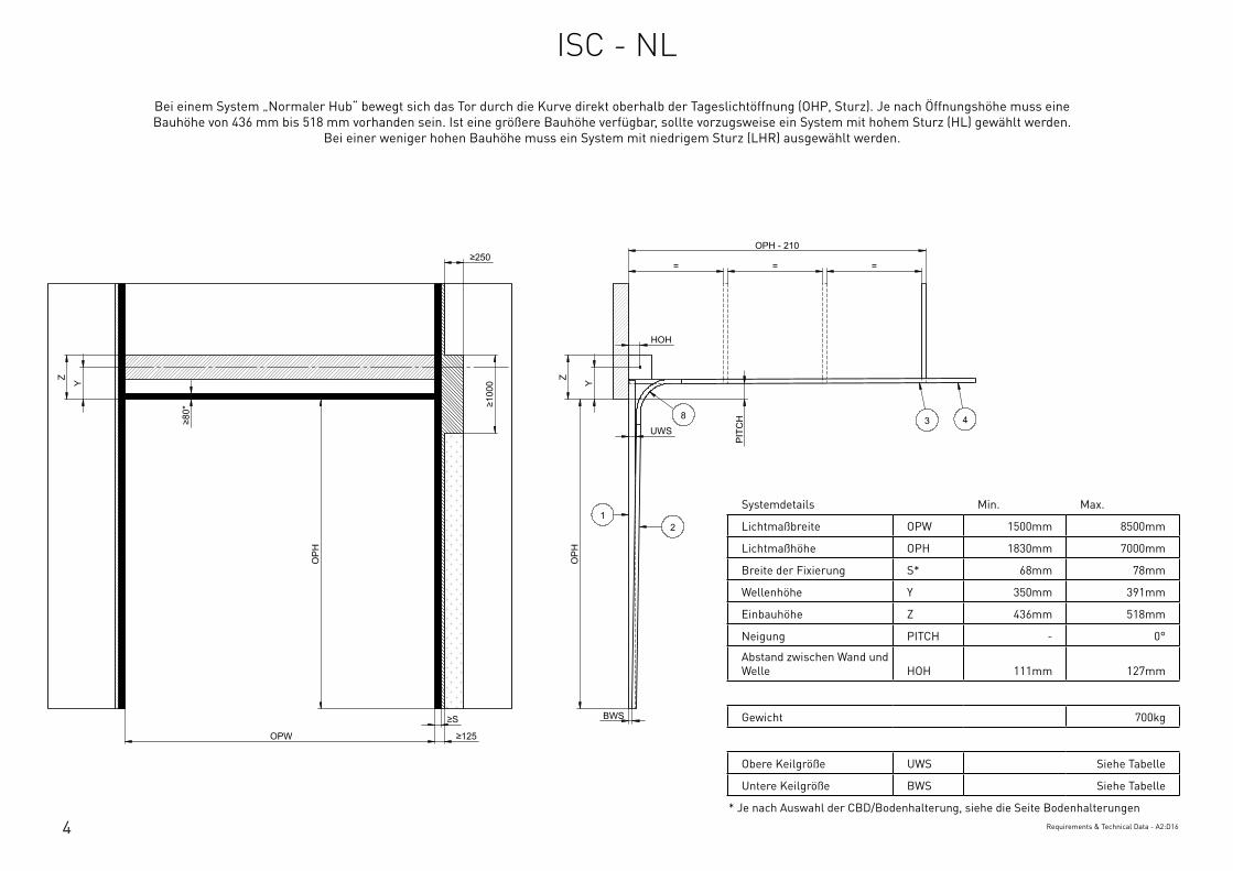
Systemdetails Min. Max.
Lichtmaßbreite OPW 1500mm 8500mm
Lichtmaßhöhe OPH 1830mm 7000mm
Breite der Fixierung S* 68mm 78mm
Wellenhöhe Y 350mm 391mm
Einbauhöhe Z 436mm 518mm
Neigung PITCH - 0°
Abstand zwischen Wand und Welle HOH 111mm 127mm
Gewicht 700kg
Obere Keilgröße UWS Siehe Tabelle
Untere Keilgröße BWS Siehe Tabelle
* Je nach Auswahl der CBD/Bodenhalterung, siehe die Seite BodenhalterungenRequirements & Technical Data - A2:D16
OPH
UWS
HOH
Y
BWS
Z
PIT
CH
OPH
OPW
≥S
≥125
≥10
00
≥80
*
Y Z
OPH - 210
= = = ≥250
12
3 48
This
wor
k is
cop
yrig
ht a
nd n
o pa
rt m
ay b
e re
prod
uced
, by
any
proc
ess,
nor
may
any
oth
er e
xclu
sive
righ
t be
exer
cise
d w
ithou
t the
per
mis
sion
of A
SSA
ABLO
Y.
Surface treatment:
V9_2
019_
02_2
1_dr
wRev.:Document ID
Material: General tolerance:
Volume: Mass: Surface area: Created (YYYY-MM-DD): Designed by: Drawn by: Scale: Projection:
Alternate ID289465723.43 mm³ 1:100 (A3)54462775.75 mm²289465.72 gram
ISO 8015ISO 2768-mH
1SHEET 1 OF 1Configuration:ISC-NL
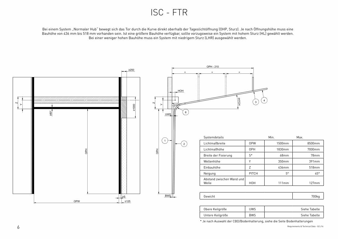
Bei einem System „Normaler Hub“ bewegt sich das Tor durch die Kurve direkt oberhalb der Tageslichtöffnung (OHP, Sturz). Je nach Öffnungshöhe muss eine Bauhöhe von 436 mm bis 518 mm vorhanden sein. Ist eine größere Bauhöhe verfugbar, sollte vorzugsweise ein System mit hohem Sturz (HL) gewählt werden.
Bei einer weniger hohen Bauhöhe muss ein System mit niedrigem Sturz (LHR) ausgewählt werden.
ISC - NL
5
Systemdetails Min. Max.
Lichtmaßbreite OPW 1500mm 8500mm
Lichtmaßhöhe OPH 1830mm 7000mm
Breite der Fixierung S* 68mm 78mm
Wellenhöhe Y 350mm 391mm
Einbauhöhe Z 436mm 518mm
Neigung PITCH - 0°
Abstand zwischen Wand und Welle HOH 111mm 127mm
Gewicht 700kg
Obere Keilgröße UWS Siehe Tabelle
Untere Keilgröße BWS Siehe Tabelle
* Je nach Auswahl der CBD/Bodenhalterung, siehe die Seite BodenhalterungenRequirements & Technical Data - A2:D16
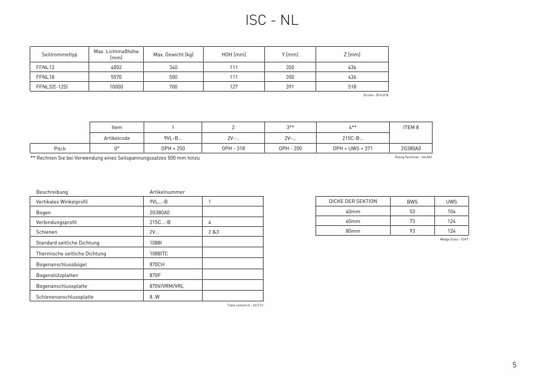
Beschreibung Artikelnummer
Vertikales Winkelprofil 9VL…-B 1
Bogen 2G380A0
Verbindungsprofil 215C…-B 4
Schienen 2V… 2 &3
Standard seitliche Dichtung 1088I
Thermische seitliche Dichtung 1088ITC
Bogenanschlussbugel 870CH
Bogenstutzplatten 870F
Bogenanschlussplatte 870V/VRM/VRL
Schienenanschlussplatte 8..WTrack consist of - A2:C13
Seiltrommeltyp Max. Lichtmaßhöhe (mm) Max. Gewicht (kg) HOH [mm] Y [mm] Z [mm]
FFNL13 4002 340 111 350 436
FFNL18 5570 500 111 350 436
FFNL32(-125) 10000 700 127 391 518Drums - B14:G18
Item 1 2 3** 4** ITEM 8
Artikelcode 9VL-B… 2V-… 2V-… 215C-B…
Pitch 0° OPH + 250 OPH - 318 OPH - 200 OPH + UWS + 371 2G380A0
** Rechnen Sie bei Verwendung eines Seilspannungssatzes 500 mm hinzu Ruling Technical - U4:AA7
DICKE DER SEKTION BWS UWS
40mm 53 104
60mm 73 124
80mm 93 124Wedge Sizes - I3:K7
ISC - NL
6
Systemdetails Min. Max.
Lichtmaßbreite OPW 1500mm 8500mm
Lichtmaßhöhe OPH 1830mm 7000mm
Breite der Fixierung S* 68mm 78mm
Wellenhöhe Y 350mm 391mm
Einbauhöhe Z 436mm 518mm
Neigung PITCH 5° 45°
Abstand zwischen Wand und Welle HOH 111mm 127mm
Gewicht 700kg
Obere Keilgröße UWS Siehe Tabelle
Untere Keilgröße BWS Siehe Tabelle
* Je nach Auswahl der CBD/Bodenhalterung, siehe die Seite BodenhalterungenRequirements & Technical Data - G2:J16
OPH
UWS
HOH
Y
BWS
Z
PITCH
OPH
OPW
≥S
≥125
≥10
00
≥80
*
Y Z
OPH - 210
= = = ≥250
12
3 4
8
This
wor
k is
cop
yrig
ht a
nd n
o pa
rt m
ay b
e re
prod
uced
, by
any
proc
ess,
nor
may
any
oth
er e
xclu
sive
righ
t be
exer
cise
d w
ithou
t the
per
mis
sion
of A
SSA
ABLO
Y.
Surface treatment:
V9_2
019_
02_2
1_dr
wRev.:Document ID
Material: General tolerance:
Volume: Mass: Surface area: Created (YYYY-MM-DD): Designed by: Drawn by: Scale: Projection:
Alternate ID289310826.07 mm³ 1:100 (A3)54414606.92 mm²289310.83 gram
ISO 8015ISO 2768-mH
1SHEET 1 OF 1Configuration:ISC-FTR
Bei einem System „Normaler Hub“ bewegt sich das Tor durch die Kurve direkt oberhalb der Tageslichtöffnung (OHP, Sturz). Je nach Öffnungshöhe muss eine Bauhöhe von 436 mm bis 518 mm vorhanden sein. Ist eine größere Bauhöhe verfugbar, sollte vorzugsweise ein System mit hohem Sturz (HL) gewählt werden.
Bei einer weniger hohen Bauhöhe muss ein System mit niedrigem Sturz (LHR) ausgewählt werden.
ISC - FTR

7
Beschreibung Artikelnummer
Vertikales Winkelprofil 9VL…-B 1
Bogen 2G380A…
Verbindungsprofil 215C…-B 4
Schienen 2V… 2 & 3
Standard seitliche Dichtung 1088I
Thermische seitliche Dichtung 1088ITC
Bogenanschlussbugel 870CH
Bogenstutzplatten 870F
Bogenanschlussplatte 870V/VRM/VRL
Schienenanschlussplatte 8..WTrack consist of - F2:H13
Seiltrommeltyp Max. Lichtmaßhöhe (mm) Max. Gewicht (kg) HOH [mm] Y [mm] Z [mm] Neigung
FFNL13 4002 340 111 350 436 < 40°
FFNL18 5570 500 111 350 436 < 40°
FFNL32(-125) 10000 700 127 391 518 < 40°
FFVL11 3300 500 127 391 518 ≥ 40°
FFVL18(-125) 6000 500 152 416 568 ≥ 40°Drums - B22:H28
Item 1 2 3** 4** ITEM 8
Artikelcode 9VL-B… 2V-… 2V-… 215C-B…
Pitch 5° OPH + 250 OPH - 288 OPH - 165 OPH + UWS + 371 2G380A5
10° OPH + 250 OPH - 248 OPH - 130 OPH + UWS + 371 2G380A10
15° OPH + 250 OPH - 318 OPH - 95 OPH + UWS + 376 2G380A15
20° OPH + 250 OPH - 318 OPH - 60 OPH + UWS + 386 2G380A20
25° OPH + 250 OPH - 318 OPH - 25 OPH + UWS + 396 2G380A25
30° OPH + 250 OPH - 318 OPH + 10 OPH + UWS + 411 2G380A30
35° OPH + 250 OPH - 318 OPH + 45 OPH + UWS + 426 2G380A35
40° OPH + 250 OPH - 318 OPH + 80 OPH + UWS + 446 2G380A40
45° OPH + 250 OPH - 318 OPH + 115 OPH + UWS + 466 2G380A45
** Rechnen Sie bei Verwendung eines Seilspannungssatzes 500 mm hinzu Ruling Technical - U10:AA21
DICKE DER SEKTION BWS UWS
40mm 53 104
60mm 73 124
80mm 93 124Wedge Sizes - I3:K7
ISC - FTR
8
Systemdetails Min. Max.
Lichtmaßbreite OPW 1500mm 8500mm
Lichtmaßhöhe OPH 1830mm 7000mm
Max. Sturz HL 210mm 3010m
Breite der Fixierung S* 68mm 78mm
Wellenhöhe HL + Y - HL + 181mm
Einbauhöhe HL + Z - HL + 308mm
Neigung PITCH - 0°
Abstand zwischen Wand und Welle HOH - 127mm
Gewicht 500kg
Obere Keilgröße UWS Siehe Tabelle
Untere Keilgröße BWS Siehe Tabelle
* Je nach Auswahl der CBD/Bodenhalterung, siehe die Seite BodenhalterungenRequirements & Technical Data - A20:D35
OPH
UWS
HOH
BWS
PIT
CH
OPH
OPW
≥S
≥125
≥10
00
≥80
*
HL
+ Y
HL
+ Z
OPH - HL
= = =
HL
Y
Z
≥250
HL
+ Y
HL
+ Z
12
3 48
This
wor
k is
cop
yrig
ht a
nd n
o pa
rt m
ay b
e re
prod
uced
, by
any
proc
ess,
nor
may
any
oth
er e
xclu
sive
righ
t be
exer
cise
d w
ithou
t the
per
mis
sion
of A
SSA
ABLO
Y.
Surface treatment:
V9_2
019_
02_2
1_dr
wRev.:Document ID
Material: General tolerance:
Volume: Mass: Surface area: Created (YYYY-MM-DD): Designed by: Drawn by: Scale: Projection:
Alternate ID415397163.98 mm³ 1:100 (A3)74737484.21 mm²415397.16 gram
ISO 8015ISO 2768-mH
1SHEET 1 OF 1Configuration:ISC-HL-1Piece
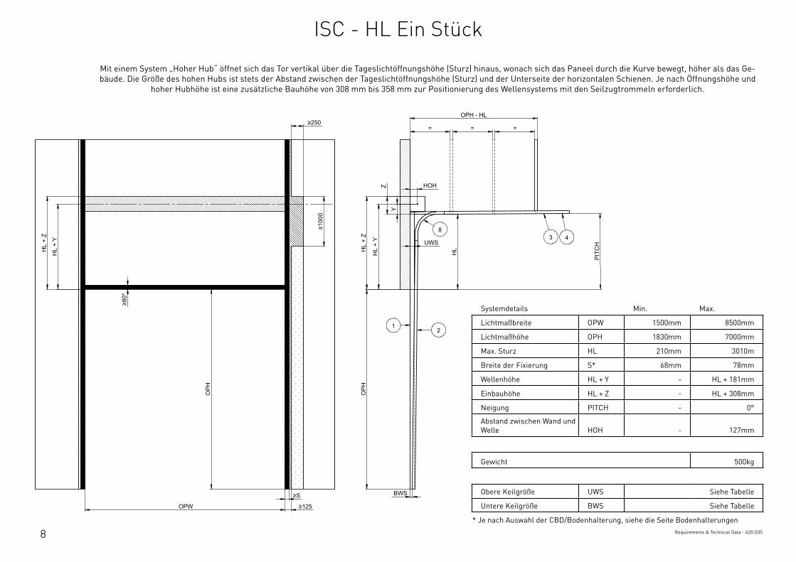
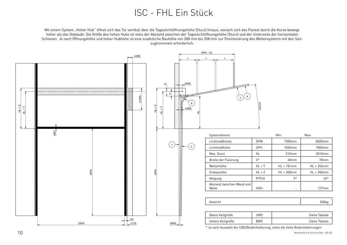
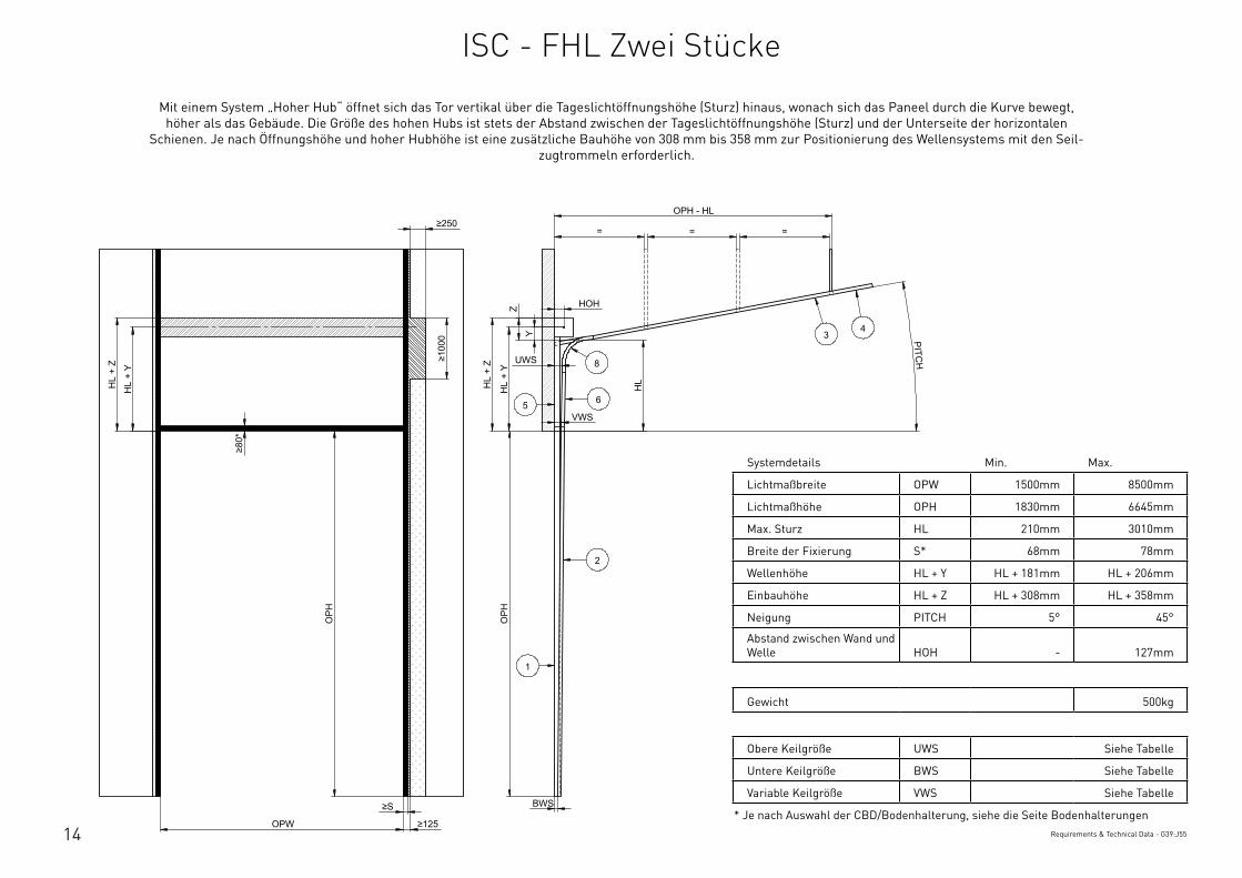
Mit einem System „Hoher Hub“ öffnet sich das Tor vertikal uber die Tageslichtöffnungshöhe (Sturz) hinaus, wonach sich das Paneel durch die Kurve bewegt, höher als das Ge-bäude. Die Größe des hohen Hubs ist stets der Abstand zwischen der Tageslichtöffnungshöhe (Sturz) und der Unterseite der horizontalen Schienen. Je nach Öffnungshöhe und
hoher Hubhöhe ist eine zusätzliche Bauhöhe von 308 mm bis 358 mm zur Positionierung des Wellensystems mit den Seilzugtrommeln erforderlich.
ISC - HL Ein Stuck
9
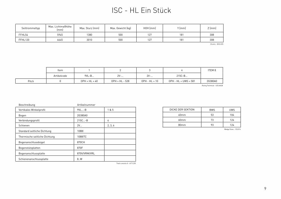
Beschreibung Artikelnummer
Vertikales Winkelprofil 9VL…-B 1 & 5
Bogen 2G380A0
Verbindungsprofil 215C…-B 4
Schienen 2V… 2, 3, 6
Standard seitliche Dichtung 1088I
Thermische seitliche Dichtung 1088ITC
Bogenanschlussbugel 870CH
Bogenstutzplatten 870F
Bogenanschlussplatte 870V/VRM/VRL
Schienenanschlussplatte 8..WTrack consist of - A17:C28
Seiltrommeltyp Max. Lichtmaßhöhe (mm) Max. Sturz (mm) Max. Gewicht (kg) HOH [mm] Y [mm] Z [mm]
FFHL54 5945 1380 500 127 181 308
FFHL120 6645 3010 500 127 181 308Drums - B32:H35
Item 1 2 3 4 ITEM 8
Artikelcode 9VL-B… 2V-… 2V-… 215C-B…
Pitch 0 OPH + HL + 40 OPH + HL - 528 OPH - HL + 10 OPH - HL + UWS + 581 2G380A0Ruling Technical - U25:AA28
DICKE DER SEKTION BWS UWS
40mm 53 104
60mm 73 124
80mm 93 124Wedge Sizes - I10:K14
ISC - HL Ein Stuck
10
Systemdetails Min. Max.
Lichtmaßbreite OPW 1500mm 8500mm
Lichtmaßhöhe OPH 1830mm 7000mm
Max. Sturz HL 210mm 3010mm
Breite der Fixierung S* 68mm 78mm
Wellenhöhe HL + Y HL + 181mm HL + 206mm
Einbauhöhe HL + Z HL + 308mm HL + 358mm
Neigung PITCH 5° 45°
Abstand zwischen Wand und Welle HOH - 127mm
Gewicht 500kg
Obere Keilgröße UWS Siehe Tabelle
Untere Keilgröße BWS Siehe Tabelle
* Je nach Auswahl der CBD/Bodenhalterung, siehe die Seite BodenhalterungenRequirements & Technical Data - G20:J35
OPH
UWS
HOH
HL
+ Y
BWS
HL
+ Z
PITCH
O
PH
OPW ≥S ≥125
≥10
00
≥80
*
HL
+ Y
HL
+ Z
OPH - HL
= = =
HL
Z
Y
≥250
12
3 4
8
This
wor
k is
cop
yrig
ht a
nd n
o pa
rt m
ay b
e re
prod
uced
, by
any
proc
ess,
nor
may
any
oth
er e
xclu
sive
righ
t be
exer
cise
d w
ithou
t the
per
mis
sion
of A
SSA
ABLO
Y.
Surface treatment:
V9_2
019_
02_2
1_dr
wRev.:Document ID
Material: General tolerance:
Volume: Mass: Surface area: Created (YYYY-MM-DD): Designed by: Drawn by: Scale: Projection:
Alternate ID415364243.14 mm³ 1:100 (A3)74721651.39 mm²415364.24 gram
ISO 8015ISO 2768-mH
1SHEET 1 OF 1Configuration:ISC-FHL-1Piece
Mit einem System „Hoher Hub“ öffnet sich das Tor vertikal uber die Tageslichtöffnungshöhe (Sturz) hinaus, wonach sich das Paneel durch die Kurve bewegt, höher als das Gebäude. Die Größe des hohen Hubs ist stets der Abstand zwischen der Tageslichtöffnungshöhe (Sturz) und der Unterseite der horizontalen
Schienen. Je nach Öffnungshöhe und hoher Hubhöhe ist eine zusätzliche Bauhöhe von 308 mm bis 358 mm zur Positionierung des Wellensystems mit den Seil-zugtrommeln erforderlich.
ISC - FHL Ein Stuck
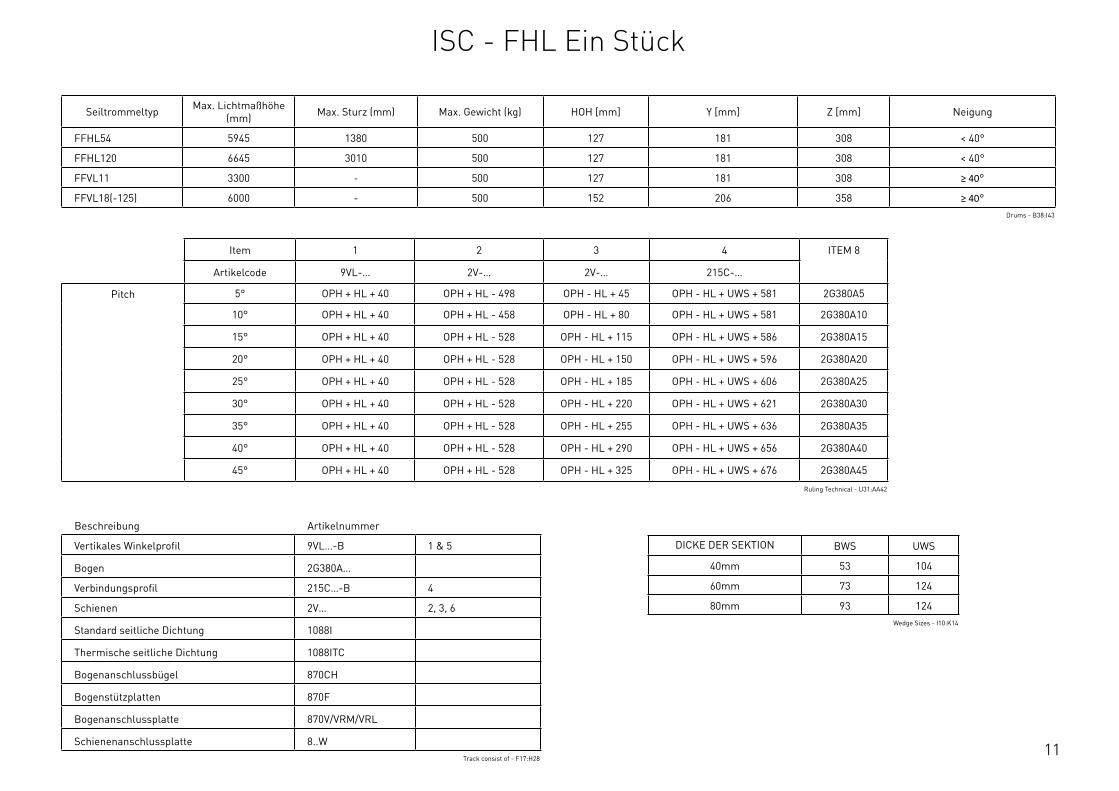
11
Beschreibung Artikelnummer
Vertikales Winkelprofil 9VL…-B 1 & 5
Bogen 2G380A…
Verbindungsprofil 215C…-B 4
Schienen 2V… 2, 3, 6
Standard seitliche Dichtung 1088I
Thermische seitliche Dichtung 1088ITC
Bogenanschlussbugel 870CH
Bogenstutzplatten 870F
Bogenanschlussplatte 870V/VRM/VRL
Schienenanschlussplatte 8..WTrack consist of - F17:H28
Seiltrommeltyp Max. Lichtmaßhöhe (mm) Max. Sturz (mm) Max. Gewicht (kg) HOH [mm] Y [mm] Z [mm] Neigung
FFHL54 5945 1380 500 127 181 308 < 40°
FFHL120 6645 3010 500 127 181 308 < 40°
FFVL11 3300 - 500 127 181 308 ≥ 40°
FFVL18(-125) 6000 - 500 152 206 358 ≥ 40°Drums - B38:I43
Item 1 2 3 4 ITEM 8
Artikelcode 9VL-… 2V-… 2V-… 215C-…
Pitch 5° OPH + HL + 40 OPH + HL - 498 OPH - HL + 45 OPH - HL + UWS + 581 2G380A5
10° OPH + HL + 40 OPH + HL - 458 OPH - HL + 80 OPH - HL + UWS + 581 2G380A10
15° OPH + HL + 40 OPH + HL - 528 OPH - HL + 115 OPH - HL + UWS + 586 2G380A15
20° OPH + HL + 40 OPH + HL - 528 OPH - HL + 150 OPH - HL + UWS + 596 2G380A20
25° OPH + HL + 40 OPH + HL - 528 OPH - HL + 185 OPH - HL + UWS + 606 2G380A25
30° OPH + HL + 40 OPH + HL - 528 OPH - HL + 220 OPH - HL + UWS + 621 2G380A30
35° OPH + HL + 40 OPH + HL - 528 OPH - HL + 255 OPH - HL + UWS + 636 2G380A35
40° OPH + HL + 40 OPH + HL - 528 OPH - HL + 290 OPH - HL + UWS + 656 2G380A40
45° OPH + HL + 40 OPH + HL - 528 OPH - HL + 325 OPH - HL + UWS + 676 2G380A45
Ruling Technical - U31:AA42
DICKE DER SEKTION BWS UWS
40mm 53 104
60mm 73 124
80mm 93 124Wedge Sizes - I10:K14
ISC - FHL Ein Stuck
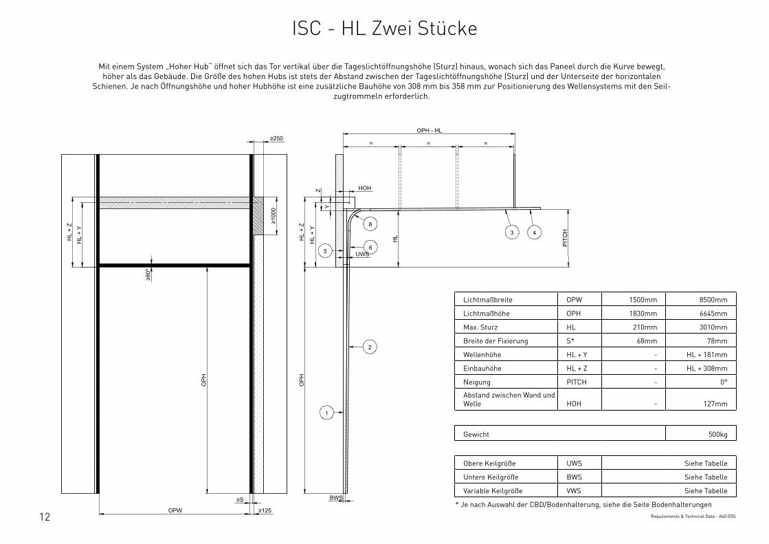
12
Lichtmaßbreite OPW 1500mm 8500mm
Lichtmaßhöhe OPH 1830mm 6645mm
Max. Sturz HL 210mm 3010mm
Breite der Fixierung S* 68mm 78mm
Wellenhöhe HL + Y - HL + 181mm
Einbauhöhe HL + Z - HL + 308mm
Neigung PITCH - 0°
Abstand zwischen Wand und Welle HOH - 127mm
Gewicht 500kg
Obere Keilgröße UWS Siehe Tabelle
Untere Keilgröße BWS Siehe Tabelle
Variable Keilgröße VWS Siehe Tabelle
* Je nach Auswahl der CBD/Bodenhalterung, siehe die Seite BodenhalterungenRequirements & Technical Data - A40:D55
OPH
UWS
HOH
HL
+ Y
BWS
HL
+ Z
PIT
CH
OPH
OPW
≥S
≥125
≥10
00
≥80
*
HL
+ Y
HL
+ Z
OPH - HL
= = =
HL
Y
Z
≥250
2
3 48
1
65
This
wor
k is
cop
yrig
ht a
nd n
o pa
rt m
ay b
e re
prod
uced
, by
any
proc
ess,
nor
may
any
oth
er e
xclu
sive
righ
t be
exer
cise
d w
ithou
t the
per
mis
sion
of A
SSA
ABLO
Y.
Surface treatment:
V9_2
019_
02_2
1_dr
wRev.:Document ID
Material: General tolerance:
Volume: Mass: Surface area: Created (YYYY-MM-DD): Designed by: Drawn by: Scale: Projection:
Alternate ID488235193.04 mm³ 1:100 (A3)89835498.33 mm²488235.19 gram
ISO 8015ISO 2768-mH
1SHEET 1 OF 1Configuration:ISC-HL-2Piece
Mit einem System „Hoher Hub“ öffnet sich das Tor vertikal uber die Tageslichtöffnungshöhe (Sturz) hinaus, wonach sich das Paneel durch die Kurve bewegt, höher als das Gebäude. Die Größe des hohen Hubs ist stets der Abstand zwischen der Tageslichtöffnungshöhe (Sturz) und der Unterseite der horizontalen
Schienen. Je nach Öffnungshöhe und hoher Hubhöhe ist eine zusätzliche Bauhöhe von 308 mm bis 358 mm zur Positionierung des Wellensystems mit den Seil-zugtrommeln erforderlich.
ISC - HL Zwei Stucke
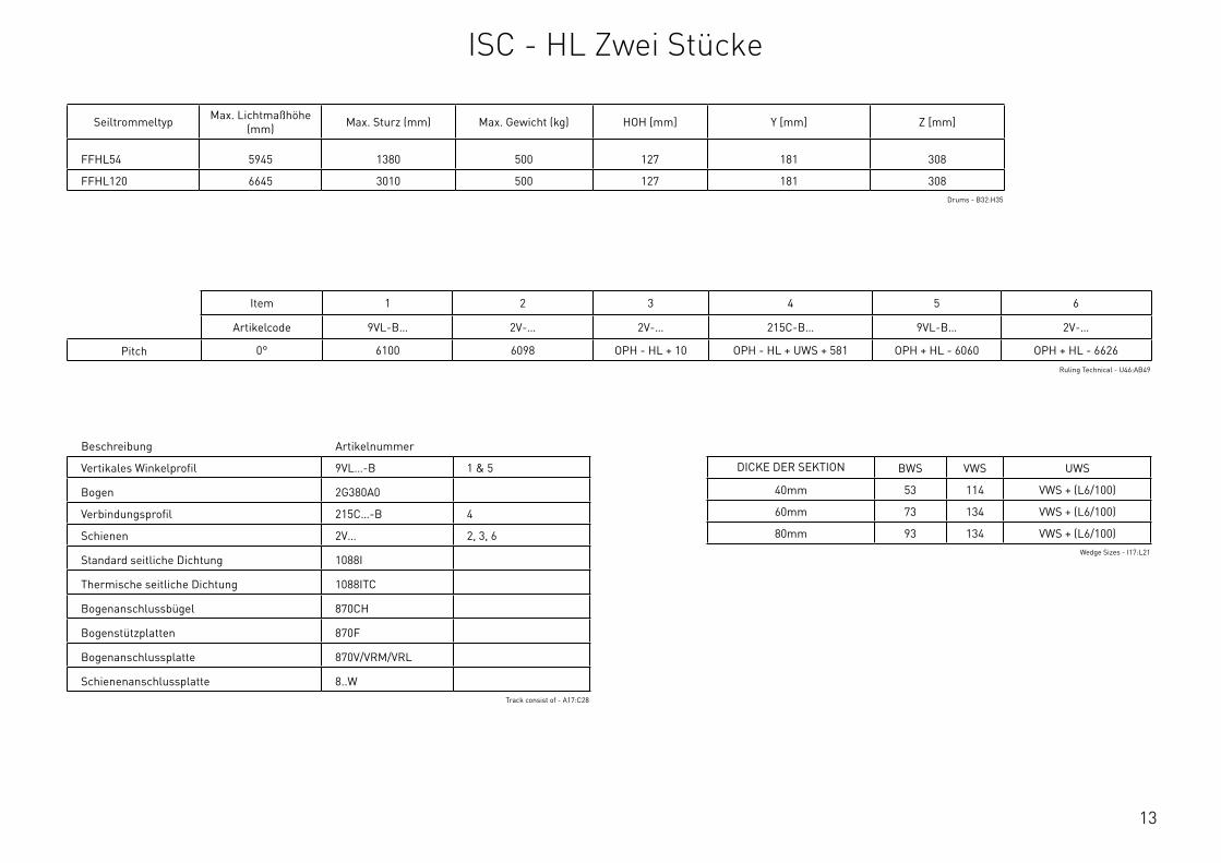
13
Beschreibung Artikelnummer
Vertikales Winkelprofil 9VL…-B 1 & 5
Bogen 2G380A0
Verbindungsprofil 215C…-B 4
Schienen 2V… 2, 3, 6
Standard seitliche Dichtung 1088I
Thermische seitliche Dichtung 1088ITC
Bogenanschlussbugel 870CH
Bogenstutzplatten 870F
Bogenanschlussplatte 870V/VRM/VRL
Schienenanschlussplatte 8..WTrack consist of - A17:C28
Seiltrommeltyp Max. Lichtmaßhöhe (mm) Max. Sturz (mm) Max. Gewicht (kg) HOH [mm] Y [mm] Z [mm]
FFHL54 5945 1380 500 127 181 308
FFHL120 6645 3010 500 127 181 308Drums - B32:H35
Item 1 2 3 4 5 6
Artikelcode 9VL-B… 2V-… 2V-… 215C-B… 9VL-B… 2V-…
Pitch 0° 6100 6098 OPH - HL + 10 OPH - HL + UWS + 581 OPH + HL - 6060 OPH + HL - 6626Ruling Technical - U46:AB49
DICKE DER SEKTION BWS VWS UWS
40mm 53 114 VWS + (L6/100)
60mm 73 134 VWS + (L6/100)
80mm 93 134 VWS + (L6/100)Wedge Sizes - I17:L21
ISC - HL Zwei Stucke
14
Systemdetails Min. Max.
Lichtmaßbreite OPW 1500mm 8500mm
Lichtmaßhöhe OPH 1830mm 6645mm
Max. Sturz HL 210mm 3010mm
Breite der Fixierung S* 68mm 78mm
Wellenhöhe HL + Y HL + 181mm HL + 206mm
Einbauhöhe HL + Z HL + 308mm HL + 358mm
Neigung PITCH 5° 45°
Abstand zwischen Wand und Welle HOH - 127mm
Gewicht 500kg
Obere Keilgröße UWS Siehe Tabelle
Untere Keilgröße BWS Siehe Tabelle
Variable Keilgröße VWS Siehe Tabelle
* Je nach Auswahl der CBD/Bodenhalterung, siehe die Seite BodenhalterungenRequirements & Technical Data - G39:J55
OPH
UWS
HOH
HL
+ Y
BWS
HL
+ Z
PITCH
O
PH
OPW
≥S
≥125
≥10
00
≥80
*
HL
+ Y
HL
+ Z
OPH - HL
= = =
HL
VWS
Z
Y
≥250
2
34
8
1
65
This
wor
k is
cop
yrig
ht a
nd n
o pa
rt m
ay b
e re
prod
uced
, by
any
proc
ess,
nor
may
any
oth
er e
xclu
sive
righ
t be
exer
cise
d w
ithou
t the
per
mis
sion
of A
SSA
ABLO
Y.
Surface treatment:
V9_2
019_
02_2
1_dr
wRev.:Document ID
Material: General tolerance:
Volume: Mass: Surface area: Created (YYYY-MM-DD): Designed by: Drawn by: Scale: Projection:
Alternate ID488036705.35 mm³ 1:100 (A3)89774518.55 mm²488036.71 gram
ISO 8015ISO 2768-mH
1SHEET 1 OF 1Configuration:ISC-FHL-2Piece
Mit einem System „Hoher Hub“ öffnet sich das Tor vertikal uber die Tageslichtöffnungshöhe (Sturz) hinaus, wonach sich das Paneel durch die Kurve bewegt, höher als das Gebäude. Die Größe des hohen Hubs ist stets der Abstand zwischen der Tageslichtöffnungshöhe (Sturz) und der Unterseite der horizontalen
Schienen. Je nach Öffnungshöhe und hoher Hubhöhe ist eine zusätzliche Bauhöhe von 308 mm bis 358 mm zur Positionierung des Wellensystems mit den Seil-zugtrommeln erforderlich.
ISC - FHL Zwei Stucke

15
Beschreibung Artikelnummer
Vertikales Winkelprofil 9VL…-B 1 & 5
Bogen 2G380A…
Verbindungsprofil 215C…-B 4
Schienen 2V… 2, 3, 6
Standard seitliche Dichtung 1088I
Thermische seitliche Dichtung 1088ITC
Bogenanschlussbugel 870CH
Bogenstutzplatten 870F
Bogenanschlussplatte 870V/VRM/VRL
Schienenanschlussplatte 8..WTrack consist of - F17:H28
Seiltrommeltyp Max. Lichtmaßhöhe (mm) Max. Sturz (mm) Max. Gewicht (kg) HOH [mm] Y [mm] Z [mm] Neigung
FFHL54 5945 1380 500 127 181 308 < 40°
FFHL120 6645 3010 500 127 181 308 < 40°
FFVL11 3300 - 500 127 181 308 ≥ 40°
FFVL18(-125) 6000 - 500 152 206 358 ≥ 40°Drums - B38:I43
Item 1 2 3 4 5 6
Artikelcode 9VL-B… 2V-… 2V-… 215C-B… 9VL-B… 2V-…
Pitch 5° 6100 6098 OPH - HL + 45 OPH - HL + UWS + 581 OPH + HL - 6060 OPH + HL - 6656
10° 6100 6098 OPH - HL + 80 OPH - HL + UWS + 581 OPH + HL - 6060 OPH + HL - 6696
15° 6100 6098 OPH - HL + 115 OPH - HL + UWS + 586 OPH + HL - 6060 OPH + HL - 6626
20° 6100 6098 OPH - HL + 150 OPH - HL + UWS + 596 OPH + HL - 6060 OPH + HL - 6626
25° 6100 6098 OPH - HL + 185 OPH - HL + UWS + 606 OPH + HL - 6060 OPH + HL - 6626
30° 6100 6098 OPH - HL + 220 OPH - HL + UWS + 621 OPH + HL - 6060 OPH + HL - 6626
35° 6100 6098 OPH - HL + 255 OPH - HL + UWS + 636 OPH + HL - 6060 OPH + HL - 6626
40° 6100 6098 OPH - HL + 290 OPH - HL + UWS + 656 OPH + HL - 6060 OPH + HL - 6626
45° 6100 6098 OPH - HL + 325 OPH - HL + UWS + 676 OPH + HL - 6060 OPH + HL - 6626
Ruling Technical - U52:AB63
DICKE DER SEKTION BWS VWS UWS
40mm 53 114 VWS + (L6/100)
60mm 73 134 VWS + (L6/100)
80mm 93 134 VWS + (L6/100)Wedge Sizes - I17:L21
ISC - FHL Zwei Stucke

16
Systemdetails Min. Max.
Lichtmaßbreite OPW 1500mm 8500mm
Lichtmaßhöhe OPH 1830mm 7000mm
Max. Sturz HL 210mm 4100mm
Breite der Fixierung S* 68mm 78mm
Wellenhöhe HL + Y - HL + 206mm
Einbauhöhe HL + Z - HL + 358mm
Neigung PITCH - 0°
Abstand zwischen Wand und Welle HOH - 127mm
Gewicht 575kg
Obere Keilgröße UWS Siehe Tabelle
Untere Keilgröße BWS Siehe Tabelle
Variable Keilgröße VWS Siehe Tabelle
* Je nach Auswahl der CBD/Bodenhalterung, siehe die Seite BodenhalterungenRequirements & Technical Data - A59:D75
OPH
UWS
HOH
HL
+ Y
BWS
HL
+ Z
PIT
CH
OPH
OPW
≥S
≥125
≥10
00
≥80
*
HL
+ Y
HL
+ Z
OPH - HL
= = =
HL
VWS
Y
Z
≥250
2
3 48
1
65
This
wor
k is
cop
yrig
ht a
nd n
o pa
rt m
ay b
e re
prod
uced
, by
any
proc
ess,
nor
may
any
oth
er e
xclu
sive
righ
t be
exer
cise
d w
ithou
t the
per
mis
sion
of A
SSA
ABLO
Y.
Surface treatment:
V9_2
019_
02_2
1_dr
wRev.:Document ID
Material: General tolerance:
Volume: Mass: Surface area: Created (YYYY-MM-DD): Designed by: Drawn by: Scale: Projection:
Alternate ID450571832.56 mm³ 1:100 (A3)82034869.87 mm²450571.83 gram
ISO 8015ISO 2768-mH
1SHEET 1 OF 1Configuration:ISC-HL-FFHL164-2Piece
Mit einem System „Hoher Hub“ öffnet sich das Tor vertikal uber die Tageslichtöffnungshöhe (Sturz) hinaus, wonach sich das Paneel durch die Kurve bewegt, höher als das Gebäude. Die Größe des hohen Hubs ist stets der Abstand zwischen der Tageslichtöffnungshöhe (Sturz) und der Unterseite der horizontalen
Schienen. Je nach Öffnungshöhe und hoher Hubhöhe ist eine zusätzliche Bauhöhe von 308 mm bis 358 mm zur Positionierung des Wellensystems mit den Seil-zugtrommeln erforderlich.
ISC - HL Zwei Stucke FFHL164
17
Beschreibung Artikelnummer
Vertikales Winkelprofil 9VL…-B 1 & 5
Bogen 2G380A0
Verbindungsprofil 215C…-B 4
Schienen 2V… 2, 3, 6
Standard seitliche Dichtung 1088I
Thermische seitliche Dichtung 1088ITC
Bogenanschlussbugel 870CH
Bogenstutzplatten 870F
Bogenanschlussplatte 870V/VRM/VRL
Schienenanschlussplatte 8..WTrack consist of - A17:C28
Seiltrommeltyp Max. Lichtmaßhöhe (mm) Max. Sturz (mm) Max. Gewicht (kg) HOH [mm] Y [mm] Z [mm]
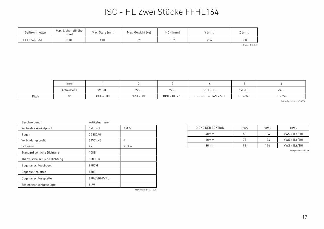
FFHL164(-125) 9881 4100 575 152 206 358Drums - B58:H60
Item 1 2 3 4 5 6
Artikelcode 9VL-B… 2V-… 2V-… 215C-B… 9VL-B… 2V-…
Pitch 0° OPH+ 300 OPH - 302 OPH - HL + 10 OPH - HL + UWS + 581 HL + 340 HL - 226Ruling Technical - U67:AB70
DICKE DER SEKTION BWS VWS UWS
40mm 53 104 VWS + (L6/60)
60mm 73 124 VWS + (L6/60)
80mm 93 124 VWS + (L6/60)Wedge Sizes - I24:L28
ISC - HL Zwei Stucke FFHL164
18
Systemdetails Min. Max.
Lichtmaßbreite OPW 1500mm 8500mm
Lichtmaßhöhe OPH 1830mm 7000mm
Max. Sturz HL 210mm 4100mm
Breite der Fixierung S* 68mm 78mm
Wellenhöhe HL + Y - HL + 206mm
Einbauhöhe HL + Z - HL + 358mm
Neigung PITCH 5° 35°
Abstand zwischen Wand und Welle HOH - 127mm
Gewicht 575kg
Obere Keilgröße UWS Siehe Tabelle
Untere Keilgröße BWS Siehe Tabelle
Variable Keilgröße VWS Siehe Tabelle
* Je nach Auswahl der CBD/Bodenhalterung, siehe die Seite BodenhalterungenRequirements & Technical Data - G59:J75
OPH
UWS
HOH
HL
+ Y
BWS
HL
+ Z
PITCH
OPH
OPW
≥S
≥125
≥10
00
≥80
*
HL
+ Y
HL
+ Z
OPH - HL
= = =
HL
VWS
Z
Y
≥250
2
3 4
8
1
65
This
wor
k is
cop
yrig
ht a
nd n
o pa
rt m
ay b
e re
prod
uced
, by
any
proc
ess,
nor
may
any
oth
er e
xclu
sive
righ
t be
exer
cise
d w
ithou
t the
per
mis
sion
of A
SSA
ABLO
Y.
Surface treatment:
V9_2
019_
02_2
1_dr
wRev.:Document ID
Material: General tolerance:
Volume: Mass: Surface area: Created (YYYY-MM-DD): Designed by: Drawn by: Scale: Projection:
Alternate ID450101481.54 mm³ 1:100 (A3)81922696.8 mm²450101.48 gram
ISO 8015ISO 2768-mH
1SHEET 1 OF 1Configuration:ISC-FHL-FFHL164-2Piece
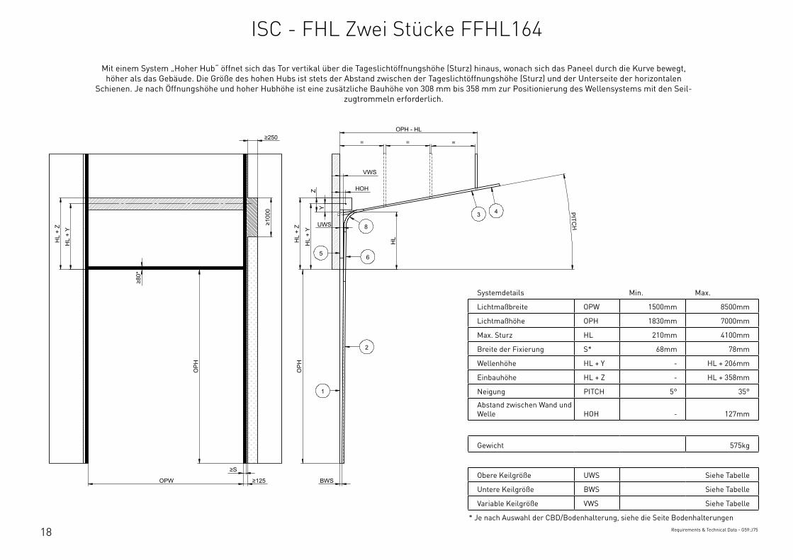
Mit einem System „Hoher Hub“ öffnet sich das Tor vertikal uber die Tageslichtöffnungshöhe (Sturz) hinaus, wonach sich das Paneel durch die Kurve bewegt, höher als das Gebäude. Die Größe des hohen Hubs ist stets der Abstand zwischen der Tageslichtöffnungshöhe (Sturz) und der Unterseite der horizontalen
Schienen. Je nach Öffnungshöhe und hoher Hubhöhe ist eine zusätzliche Bauhöhe von 308 mm bis 358 mm zur Positionierung des Wellensystems mit den Seil-zugtrommeln erforderlich.
ISC - FHL Zwei Stucke FFHL164

19
Beschreibung Artikelnummer
Vertikales Winkelprofil 9VL…-B 1 & 5
Bogen 2G380A…
Verbindungsprofil 215C…-B 4
Schienen 2V… 2, 3, 6
Standard seitliche Dichtung 1088I
Thermische seitliche Dichtung 1088ITC
Bogenanschlussbugel 870CH
Bogenstutzplatten 870F
Bogenanschlussplatte 870V/VRM/VRL
Schienenanschlussplatte 8..WTrack consist of - F17:H28
Seiltrommeltyp Max. Lichtmaßhöhe (mm) Max. Sturz (mm) Max. Gewicht (kg) HOH [mm] Y [mm] Z [mm] Neigung
FFHL164(-125) 9881 4100 575 152 206 358 < 40°Drums - B63:I65
Item 1 2 3 4 5 6
Artikelcode 9VL-B… 2V-… 2V-… 215C-B… 9VL-B… 2V-…
Pitch 5° OPH+ 300 OPH - 302 OPH - HL + 45 OPH - HL + UWS + 581 HL + 340 HL - 196
10° OPH+ 300 OPH - 302 OPH - HL + 80 OPH - HL + UWS + 581 HL + 340 HL - 156
15° OPH+ 300 OPH - 302 OPH - HL + 115 OPH - HL + UWS + 586 HL + 340 HL - 226
20° OPH+ 300 OPH - 302 OPH - HL + 150 OPH - HL + UWS + 596 HL + 340 HL - 226
25° OPH+ 300 OPH - 302 OPH - HL + 185 OPH - HL + UWS + 606 HL + 340 HL - 226
30° OPH+ 300 OPH - 302 OPH - HL + 220 OPH - HL + UWS + 621 HL + 340 HL - 226
35° OPH+ 300 OPH - 302 OPH - HL + 255 OPH - HL + UWS + 636 HL + 340 HL - 226
40° OPH+ 300 OPH - 302 OPH - HL + 290 OPH - HL + UWS + 656 HL + 340 HL - 226
45° OPH+ 300 OPH - 302 OPH - HL + 325 OPH - HL + UWS + 676 HL + 340 HL - 226
Ruling Technical - U73:AB84
DICKE DER SEKTION BWS VWS UWS
40mm 53 104 VWS + (L6/60)
60mm 73 124 VWS + (L6/60)
80mm 93 124 VWS + (L6/60)Wedge Sizes - I24:L28
ISC - FHL Zwei Stucke FFHL164
20
Systemdetails Min. Max.
Lichtmaßbreite OPW 1500mm 8500mm
Lichtmaßhöhe OPH 1830mm 3300mm
Breite der Fixierung S* 68mm 78mm
Wellenhöhe Y 127mm 152mm
Einbauhöhe Z 254mm 304mm
Obere Keilgröße UWS Siehe Tabelle
Untere Keilgröße BWS Siehe Tabelle
Gewicht 500kg
* Je nach Auswahl der CBD/Bodenhalterung, siehe die Seite BodenhalterungenRequirements & Technical Data - A79:D91
OPH
HOH
Y
BWS
Z
OPH
OPW ≥S ≥125
≥80
≥250
≥10
00
UWS
(2 x
OPH
) + 3
00
(2 x
OPH
) + 3
00 +
Y
(2 x
OPH
) + 3
00 +
Z 2
1
This
wor
k is
cop
yrig
ht a
nd n
o pa
rt m
ay b
e re
prod
uced
, by
any
proc
ess,
nor
may
any
oth
er e
xclu
sive
righ
t be
exer
cise
d w
ithou
t the
per
mis
sion
of A
SSA
ABLO
Y.
Surface treatment:
V9_2
019_
02_2
1_dr
wRev.:Document ID
Material: General tolerance:
Volume: Mass: Surface area: Created (YYYY-MM-DD): Designed by: Drawn by: Scale: Projection:
Alternate ID531320092.93 mm³ 1:100 (A3)90915516.55 mm²531320.09 gram
ISO 8015ISO 2768-mH
1SHEET 1 OF 1Configuration:ISC-VL-1Piece
Bei einem System „Vertikaler Hub“ bewegt sich das Tor von der Tageslichtöffnungshöhe (OPH) gerade nach oben, was impliziert, dass wenigstens fur die kom-plette Torhöhe ausreichend Bauhöhe verfugbar sein muss. Das System hat keine Kurve. Bei Systemen mit vertikalem Hub hängt das komplette Torgewicht in
allen Torpositionen an den Hebeseilzugen.
ISC - VL Ein Stuck

21
Beschreibung Artikelnummer
Vertikales Winkelprofil 9VL…-B 1 & 5
Schienen 2V… 2 & 6
Standard seitliche Dichtung 1088I
Thermische seitliche Dichtung 1088ITC
Schienenanschlussplatte 8..WTrack consist of - A32:C38
Seiltrommeltyp Max. Lichtmaßhöhe (mm) Max. Gewicht (kg) HOH [mm] Y [mm] Z [mm]
FFVL11 3300 500 127 127 254
FFVL18(-125) 6000 500 152 152 304Drums - B46:G49
Item 1 2
Artikelcode 9VL-B… 2V-…
2xOPH + 300 2xOPH + 300
Ruling Technical - U107:W110
DICKE DER SEKTION BWS VWS UWS
40mm 53 131 155
60mm 73(BWS + UWS)
/ 2 min. 0,4°
80mm 93(BWS + UWS)
/ 2 min. 0,4°Wedge Sizes - I31:L35
ISC - VL Ein Stuck
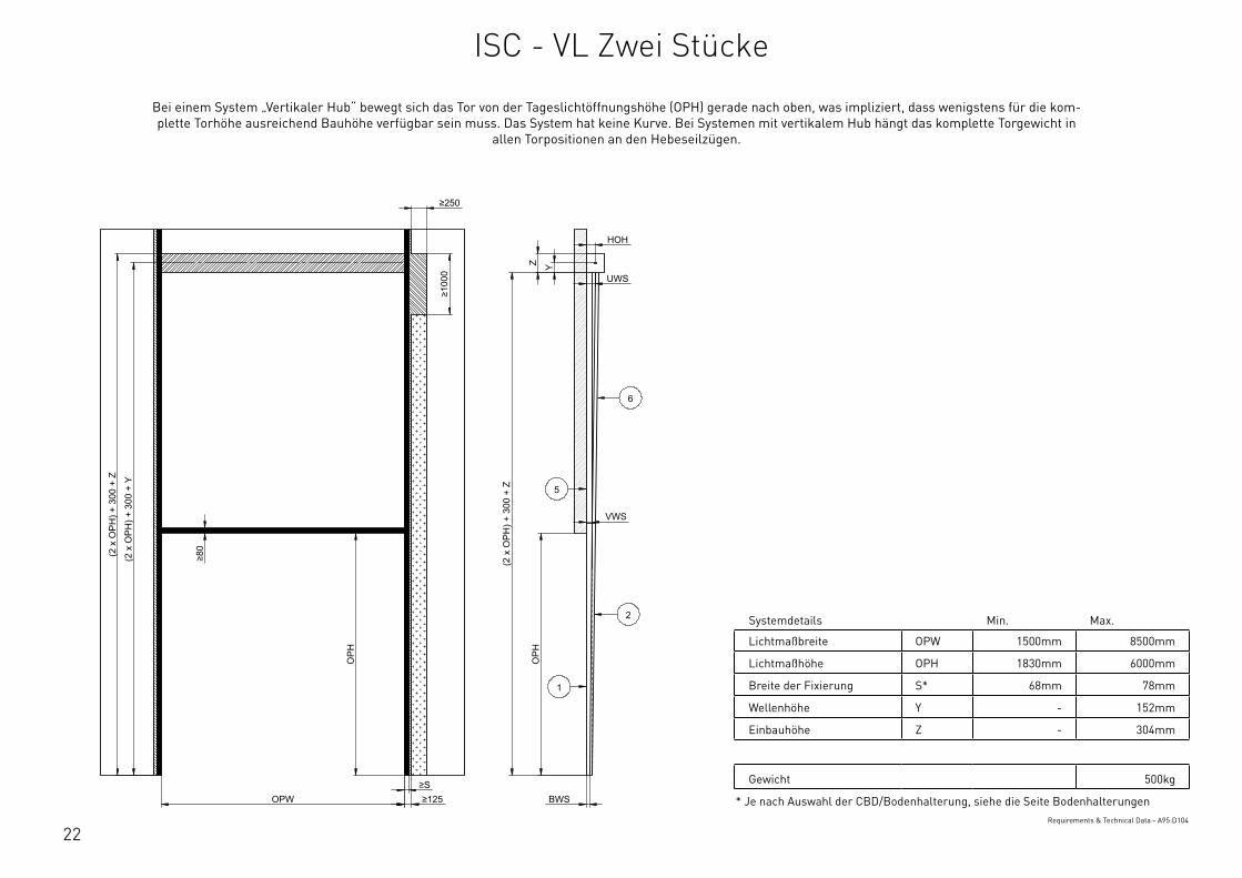
22
Systemdetails Min. Max.
Lichtmaßbreite OPW 1500mm 8500mm
Lichtmaßhöhe OPH 1830mm 6000mm
Breite der Fixierung S* 68mm 78mm
Wellenhöhe Y - 152mm
Einbauhöhe Z - 304mm
Gewicht 500kg
* Je nach Auswahl der CBD/Bodenhalterung, siehe die Seite BodenhalterungenRequirements & Technical Data - A95:D104
OPH
HOH
Y
BWS
Z
OPH
OPW ≥S ≥125
≥80
≥250
≥10
00
UWS
VWS (2
x O
PH) +
300
+ Z
(2 x
OPH
) + 3
00 +
Y
(2 x
OPH
) + 3
00 +
Z
2
1
6
5
This
wor
k is
cop
yrig
ht a
nd n
o pa
rt m
ay b
e re
prod
uced
, by
any
proc
ess,
nor
may
any
oth
er e
xclu
sive
righ
t be
exer
cise
d w
ithou
t the
per
mis
sion
of A
SSA
ABLO
Y.
Surface treatment:
V9_2
019_
02_2
1_dr
wRev.:Document ID
Material: General tolerance:
Volume: Mass: Surface area: Created (YYYY-MM-DD): Designed by: Drawn by: Scale: Projection:
Alternate ID552648112.93 mm³ 1:100 (A3)95351980.55 mm²552648.11 gram
ISO 8015ISO 2768-mH
1SHEET 1 OF 1Configuration:ISC-VL-2Piece
Bei einem System „Vertikaler Hub“ bewegt sich das Tor von der Tageslichtöffnungshöhe (OPH) gerade nach oben, was impliziert, dass wenigstens fur die kom-plette Torhöhe ausreichend Bauhöhe verfugbar sein muss. Das System hat keine Kurve. Bei Systemen mit vertikalem Hub hängt das komplette Torgewicht in
allen Torpositionen an den Hebeseilzugen.
ISC - VL Zwei Stucke
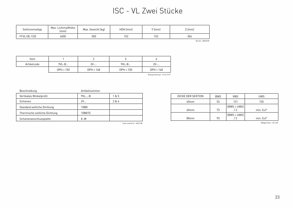
23
Beschreibung Artikelnummer
Vertikales Winkelprofil 9VL…-B 1 & 5
Schienen 2V… 2 & 6
Standard seitliche Dichtung 1088I
Thermische seitliche Dichtung 1088ITC
Schienenanschlussplatte 8..WTrack consist of - A32:C38
Seiltrommeltyp Max. Lichtmaßhöhe (mm) Max. Gewicht (kg) HOH [mm] Y [mm] Z [mm]
FFVL18(-125) 6000 500 152 152 304Drums - B68:G70
Item 1 2 5 6
Artikelcode 9VL-B… 2V-… 9VL-B… 2V-…
OPH + 150 OPH + 148 OPH + 150 OPH + 148
Ruling Technical - U114:Y117
DICKE DER SEKTION BWS VWS UWS
40mm 53 131 155
60mm 73(BWS + UWS)
/ 2 min. 0,4°
80mm 93(BWS + UWS)
/ 2 min. 0,4°Wedge Sizes - I31:L35
ISC - VL Zwei Stucke
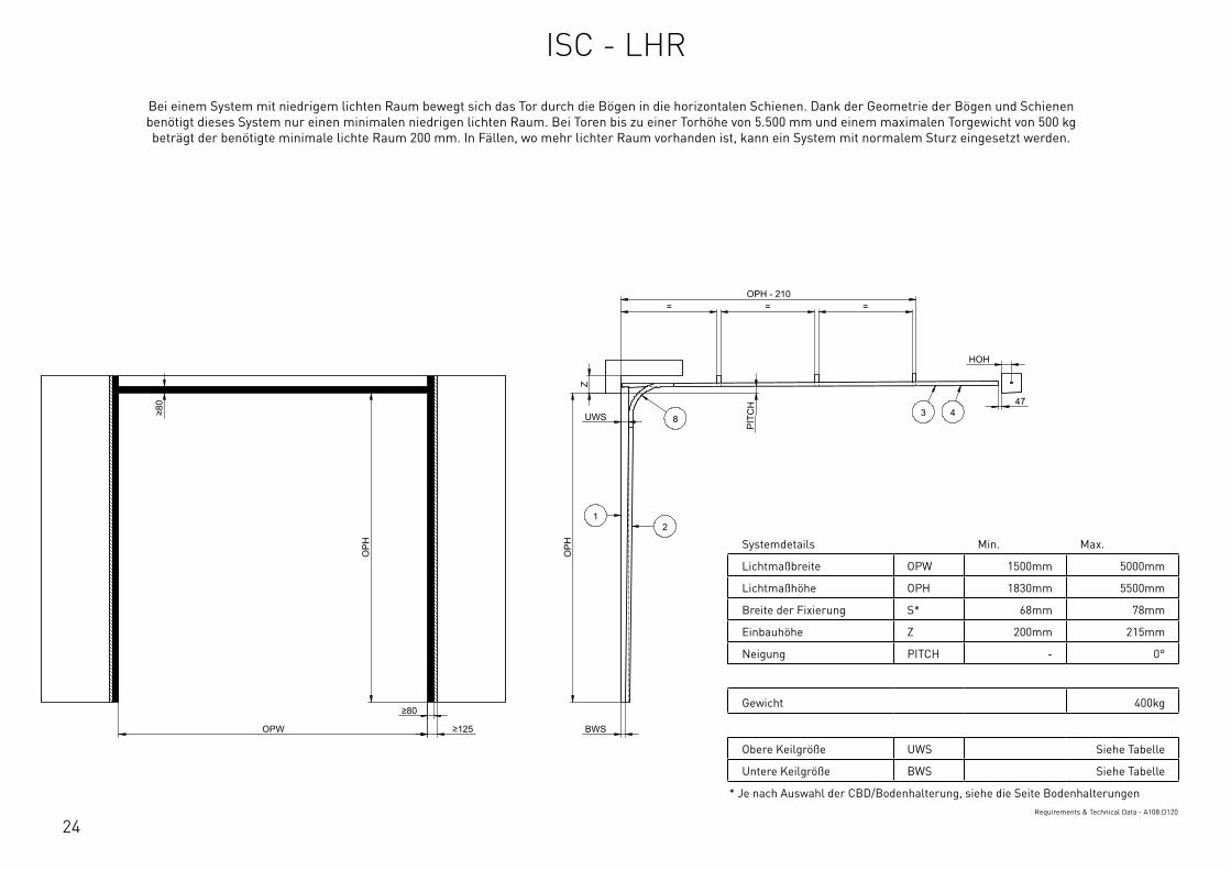
24
Systemdetails Min. Max.
Lichtmaßbreite OPW 1500mm 5000mm
Lichtmaßhöhe OPH 1830mm 5500mm
Breite der Fixierung S* 68mm 78mm
Einbauhöhe Z 200mm 215mm
Neigung PITCH - 0°
Gewicht 400kg
Obere Keilgröße UWS Siehe Tabelle
Untere Keilgröße BWS Siehe Tabelle
* Je nach Auswahl der CBD/Bodenhalterung, siehe die Seite BodenhalterungenRequirements & Technical Data - A108:D120
OPH
UWS
BWS
PIT
CH
OPW
OPH
≥80
≥80
≥125
HOH
47
= = = OPH - 210
Z
12
3 48
This
wor
k is
cop
yrig
ht a
nd n
o pa
rt m
ay b
e re
prod
uced
, by
any
proc
ess,
nor
may
any
oth
er e
xclu
sive
righ
t be
exer
cise
d w
ithou
t the
per
mis
sion
of A
SSA
ABLO
Y.
Surface treatment:
V9_2
019_
02_2
1_dr
wRev.:Document ID
Material: General tolerance:
Volume: Mass: Surface area: Created (YYYY-MM-DD): Designed by: Drawn by: Scale: Projection:
Alternate ID142976550.27 mm³ 1:100 (A3)25577248.67 mm²142976.55 gram
ISO 8015ISO 2768-mH
1SHEET 1 OF 1Configuration:ISC-LHR
Bei einem System mit niedrigem lichten Raum bewegt sich das Tor durch die Bögen in die horizontalen Schienen. Dank der Geometrie der Bögen und Schienen benötigt dieses System nur einen minimalen niedrigen lichten Raum. Bei Toren bis zu einer Torhöhe von 5.500 mm und einem maximalen Torgewicht von 500 kg beträgt der benötigte minimale lichte Raum 200 mm. In Fällen, wo mehr lichter Raum vorhanden ist, kann ein System mit normalem Sturz eingesetzt werden.
ISC - LHR
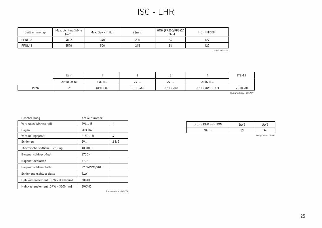
25
Seiltrommeltyp Max. Lichtmaßhöhe (mm) Max. Gewicht (kg) Z [mm] HOH (FF200/FF263/
FF375) HOH (FF600)
FFNL13 4002 340 200 86 127
FFNL18 5570 500 215 86 127Drums - B52:G55
Item 1 2 3 4 ITEM 8
Artikelcode 9VL-B… 2V-… 2V-… 215C-B…
Pitch 0° OPH + 80 OPH - 452 OPH + 200 OPH + UWS + 771 2G380A0Ruling Technical - U88:AA91
DICKE DER SEKTION BWS UWS
40mm 53 94Wedge Sizes - I38:K40
Beschreibung Artikelnummer
Vertikales Winkelprofil 9VL…-B 1
Bogen 2G380A0
Verbindungsprofil 215C…-B 4
Schienen 2V… 2 & 3
Thermische seitliche Dichtung 1088ITC
Bogenanschlussbugel 870CH
Bogenstutzplatten 870F
Bogenanschlussplatte 870V/VRM/VRL
Schienenanschlussplatte 8..W
Hohlkastenelement (OPW < 3500 mm) 60K40
Hohlkastenelement (OPW > 3500mm) 60K403Track consist of - A42:C54
ISC - LHR
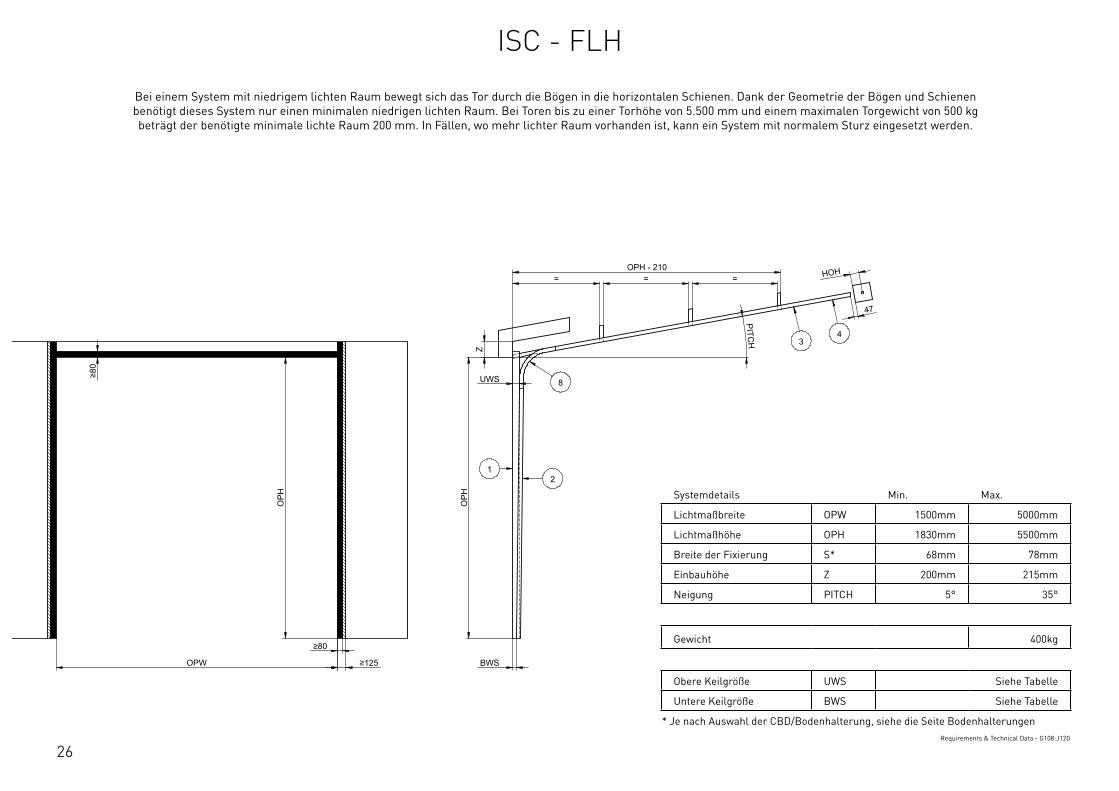
26
Systemdetails Min. Max.
Lichtmaßbreite OPW 1500mm 5000mm
Lichtmaßhöhe OPH 1830mm 5500mm
Breite der Fixierung S* 68mm 78mm
Einbauhöhe Z 200mm 215mm
Neigung PITCH 5° 35°
Gewicht 400kg
Obere Keilgröße UWS Siehe Tabelle
Untere Keilgröße BWS Siehe Tabelle
* Je nach Auswahl der CBD/Bodenhalterung, siehe die Seite BodenhalterungenRequirements & Technical Data - G108:J120
OPH
UWS
BWS
PITCH
OPW
OPH
≥80
≥80
≥125
HOH
47
= = = OPH - 210
Z
12
34
8
This
wor
k is
cop
yrig
ht a
nd n
o pa
rt m
ay b
e re
prod
uced
, by
any
proc
ess,
nor
may
any
oth
er e
xclu
sive
righ
t be
exer
cise
d w
ithou
t the
per
mis
sion
of A
SSA
ABLO
Y.
Surface treatment:
V9_2
019_
02_2
1_dr
wRev.:Document ID
Material: General tolerance:
Volume: Mass: Surface area: Created (YYYY-MM-DD): Designed by: Drawn by: Scale: Projection:
Alternate ID142758386.18 mm³ 1:100 (A3)25601845.72 mm²142758.39 gram
ISO 8015ISO 2768-mH
1SHEET 1 OF 1Configuration:ISC-FHR
Bei einem System mit niedrigem lichten Raum bewegt sich das Tor durch die Bögen in die horizontalen Schienen. Dank der Geometrie der Bögen und Schienen benötigt dieses System nur einen minimalen niedrigen lichten Raum. Bei Toren bis zu einer Torhöhe von 5.500 mm und einem maximalen Torgewicht von 500 kg beträgt der benötigte minimale lichte Raum 200 mm. In Fällen, wo mehr lichter Raum vorhanden ist, kann ein System mit normalem Sturz eingesetzt werden.
ISC - FLH
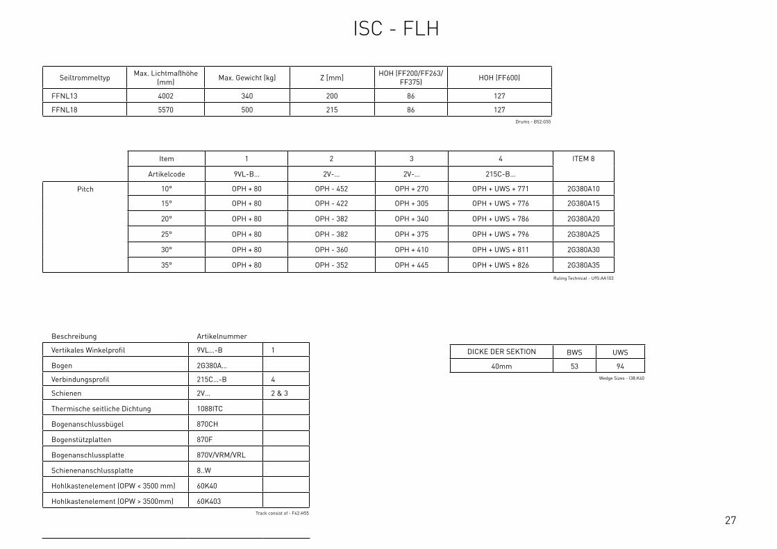
27
Seiltrommeltyp Max. Lichtmaßhöhe (mm) Max. Gewicht (kg) Z [mm] HOH (FF200/FF263/
FF375) HOH (FF600)
FFNL13 4002 340 200 86 127
FFNL18 5570 500 215 86 127Drums - B52:G55
Item 1 2 3 4 ITEM 8
Artikelcode 9VL-B… 2V-… 2V-… 215C-B…
Pitch 10° OPH + 80 OPH - 452 OPH + 270 OPH + UWS + 771 2G380A10
15° OPH + 80 OPH - 422 OPH + 305 OPH + UWS + 776 2G380A15
20° OPH + 80 OPH - 382 OPH + 340 OPH + UWS + 786 2G380A20
25° OPH + 80 OPH - 382 OPH + 375 OPH + UWS + 796 2G380A25
30° OPH + 80 OPH - 360 OPH + 410 OPH + UWS + 811 2G380A30
35° OPH + 80 OPH - 352 OPH + 445 OPH + UWS + 826 2G380A35
Ruling Technical - U95:AA103
DICKE DER SEKTION BWS UWS
40mm 53 94Wedge Sizes - I38:K40
Beschreibung Artikelnummer
Vertikales Winkelprofil 9VL…-B 1
Bogen 2G380A…
Verbindungsprofil 215C…-B 4
Schienen 2V… 2 & 3
Thermische seitliche Dichtung 1088ITC
Bogenanschlussbugel 870CH
Bogenstutzplatten 870F
Bogenanschlussplatte 870V/VRM/VRL
Schienenanschlussplatte 8..W
Hohlkastenelement (OPW < 3500 mm) 60K40
Hohlkastenelement (OPW > 3500mm) 60K403Track consist of - F42:H55
ISC - FLH
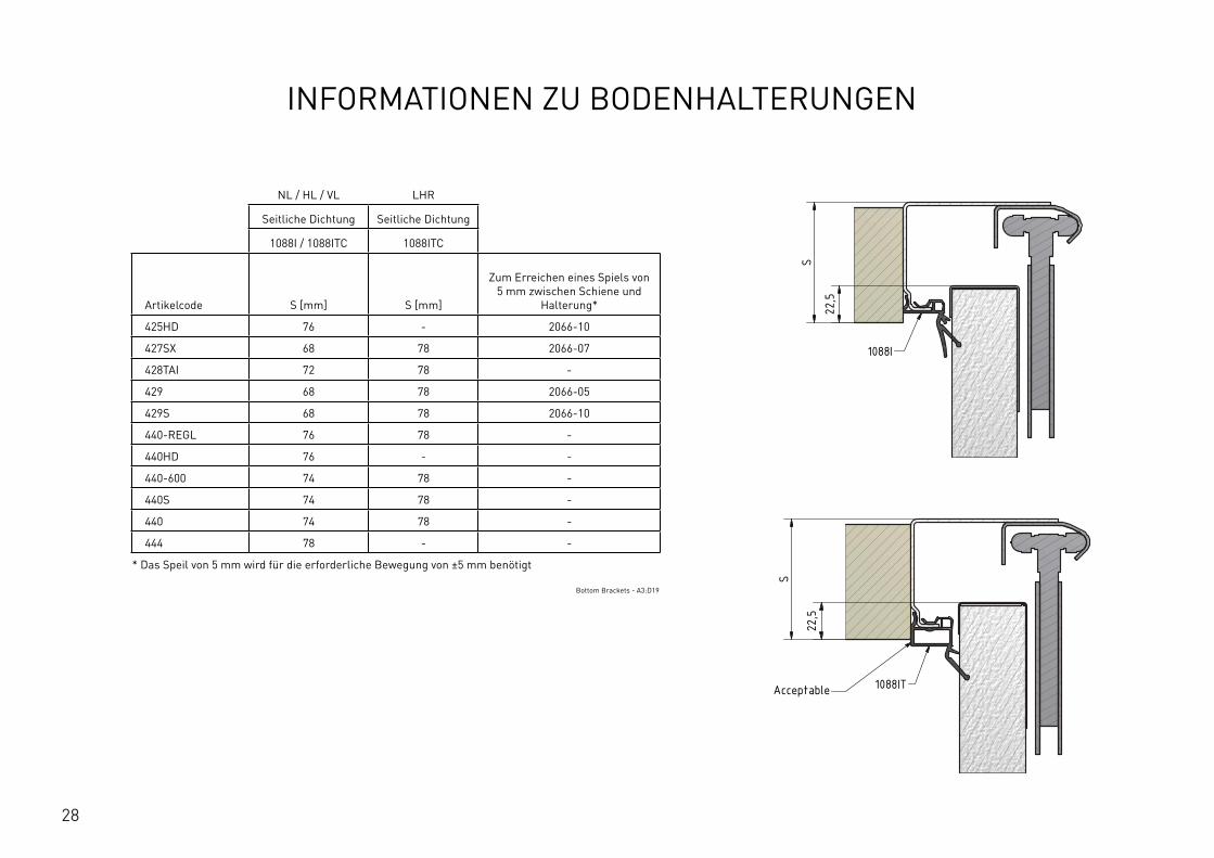
28
INFORMATIONEN ZU BODENHALTERUNGEN
NL / HL / VL LHR
Seitliche Dichtung Seitliche Dichtung
1088I / 1088ITC 1088ITC
Artikelcode S [mm] S [mm]
Zum Erreichen eines Spiels von 5 mm zwischen Schiene und
Halterung*
425HD 76 - 2066-10
427SX 68 78 2066-07
428TAI 72 78 -
429 68 78 2066-05
429S 68 78 2066-10
440-REGL 76 78 -
440HD 76 - -
440-600 74 78 -
440S 74 78 -
440 74 78 -
444 78 - -
* Das Speil von 5 mm wird fur die erforderliche Bewegung von ±5 mm benötigt
Bottom Brackets - A3:D19
E E
F F
SCALE: GENERALROUGHNESS:
PROJECTION:FORMAT: UNIT:
mmTOLERANCES UNLESS
OTHERWISE STATED Acc. To ISO 2768-cK
MATERIAL
TREATMENT
DESCRIPTION
ARTICLE CODE DRAWING NUMBER REVISION
CREATION DATE NETTO WEIGHTCREATED BY
THICKNESS
FLAT WIDTH
FLAT LENGHT
mm
mm
mm
This drawing is property ofFlexiForce
and contains confidentionalinformation.
All rights are strictly reserved.Reproduction
and use for production purposesissue to
third parties in any form whatsoever,is not permitted without written authority from the proprietors.
36 001 001 A
Position of Vertical Angle based on Side Seal and Bottom Bracket
...
JiGa 9-8-2016 538,183 kg
-
A3-
-
---
-C:\V
aultWor
kspa
ce\R
&D\T
eke n
inge
n\36
\360
0100
1\36
001 0
01\4
40 -
108
8I.ia
m
0.5-3 >3-6 >6-30 >30-120 >120-400 >400-1000 >1000-2000 >2000-4000
:
:
:
: :
: : :
: : :
±0.20 ±0.30 ±0.50 ±0.80 ±1.20 ±2.00 ±3.00 ±4.00
Nomi
nal dime
nsion
:
3
A3 Changed values in table, see excel file JiGa 20-01-2017A2 Changed values in table, see excel file JiGa 10-01-2017REV. DESCRIPTION NAME DATE
Side Seal Side Seal 1088I / 1088IT
Bottom Bracket S [mm]Technical S [mm]CommercialAdd to achieve play of 5mm between track and bracket
425HD 75,5 76 2066-10427SX 67,5 68 2066-07428TAI 72 72 -429 67,5 68 2066-05429S 67,5 68 2066-10440-REGL 75,5 76 -440HD 75,5 76 -440-600 73,5 74 -440S 73,5 74 -440 73,5 74 -444 77,5 78 -
S
22,5
1088I
22,5
S
1088ITAcceptable
The play of 5mm is needed for the required pendel of +5mm/-5mm
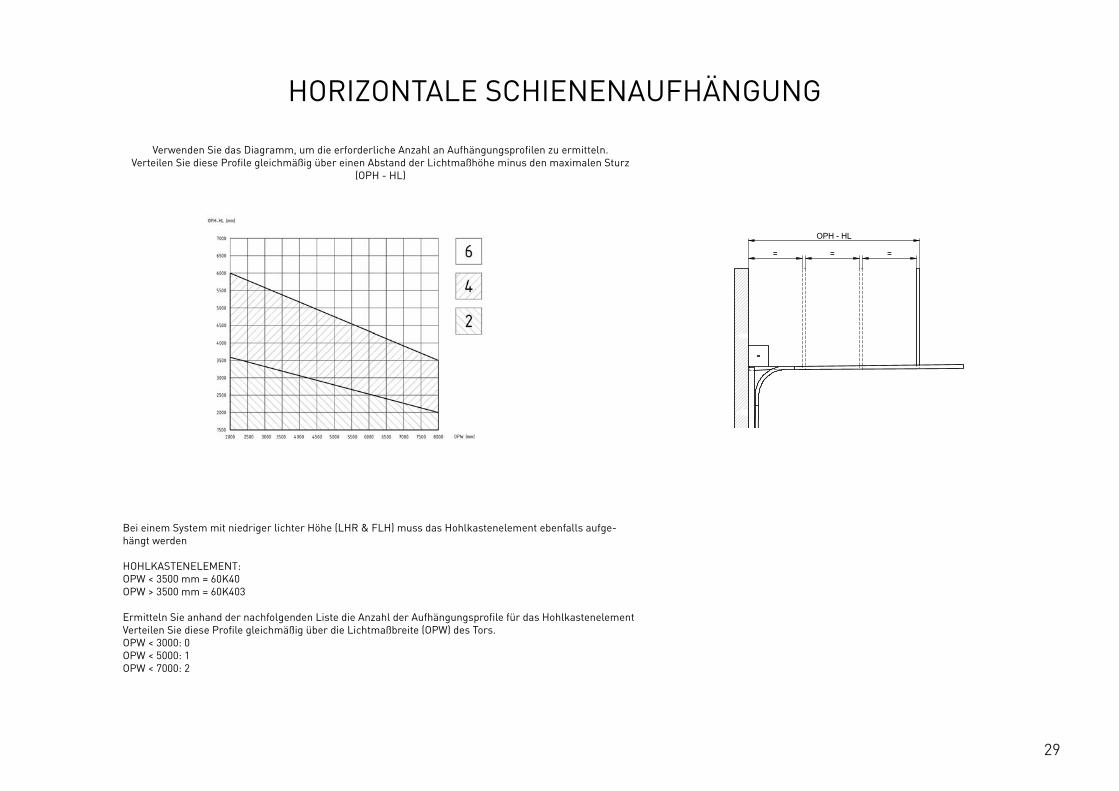
29
HORIZONTALE SCHIENENAUFHÄNGUNG
Verwenden Sie das Diagramm, um die erforderliche Anzahl an Aufhängungsprofilen zu ermitteln. Verteilen Sie diese Profile gleichmäßig uber einen Abstand der Lichtmaßhöhe minus den maximalen Sturz
(OPH - HL)
Bei einem System mit niedriger lichter Höhe (LHR & FLH) muss das Hohlkastenelement ebenfalls aufge-hängt werden HOHLKASTENELEMENT: OPW < 3500 mm = 60K40 OPW > 3500 mm = 60K403 Ermitteln Sie anhand der nachfolgenden Liste die Anzahl der Aufhängungsprofile fur das Hohlkastenelement Verteilen Sie diese Profile gleichmäßig uber die Lichtmaßbreite (OPW) des Tors. OPW < 3000: 0 OPW < 5000: 1 OPW < 7000: 2
OPH
BWS
OPH
OPW
≥S
≥125
≥10
00
≥80
*
HL
+ Y
HL
+ Z
OPH - HL
= = = ≥250
12
This
wor
k is
cop
yrig
ht a
nd n
o pa
rt m
ay b
e re
prod
uced
, by
any
proc
ess,
nor
may
any
oth
er e
xclu
sive
righ
t be
exer
cise
d w
ithou
t the
per
mis
sion
of A
SSA
ABLO
Y.
Surface treatment:
V9_2
019_
02_2
1_dr
wRev.:Document ID
Material: General tolerance:
Volume: Mass: Surface area: Created (YYYY-MM-DD): Designed by: Drawn by: Scale: Projection:
Alternate ID415397163.98 mm³ 1:100 (A3)74737484.21 mm²415397.16 gram
ISO 8015ISO 2768-mH
1SHEET 1 OF 1Configuration:ISC-HL-1Piece
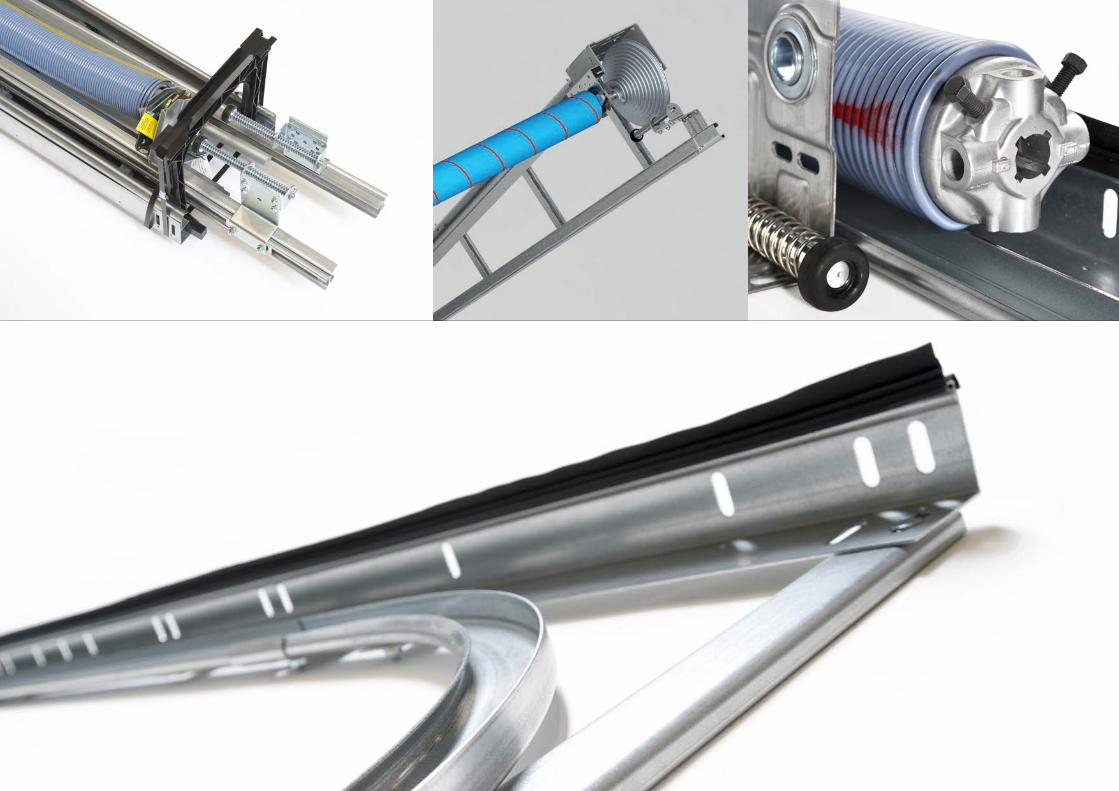
30
31
HIER FINDEN SIE UNS
FlexiForce B.V. Hanzeweg 19 3771 NG Barneveld PO Box 37 3770 AA Barneveld Niederlande +31-(0)342-427777 [email protected]
FlexiForce Hungary Kft. Medvefű str. 24 4031 Debrecen Ungarn +36-52561260 [email protected]
FlexiForce Ibérica, S.L. Apartado Correos 403 Ctra. Nacional 332, Km. 211 46780 – Oliva (Valencia) Spanien +34 96.285.82.50 [email protected]
FlexiForce Poland Sp. z o.o. Norblina 17/19 95-015 Głowno Polen +48 426500491 [email protected]
FlexiForce Italia Srl. Via deiTigli CNM 25020 Alfianello Italien +39 0309936510 [email protected]
FlexiForce Turkey Marmara Geri Donusumculer Topluİsyeri Yapı Kooperatifi Sekerpinar Mahallesi Aycicek Sokak Kapi No: 24 (245 ada, 31 parsel) 41420, Çayirova, KOCAELI / TÜRKEI +90 262 658 2058 [email protected]
www.flexiforce.com

32
GESUNDHEIT UND SICHERHEIT BEI TÜRINSTALLATIONEN!

1
TECHNISCH HANDBOEKINDUSTRIEEL ISC-HARDWARESYSTEEM
EN. 3.1
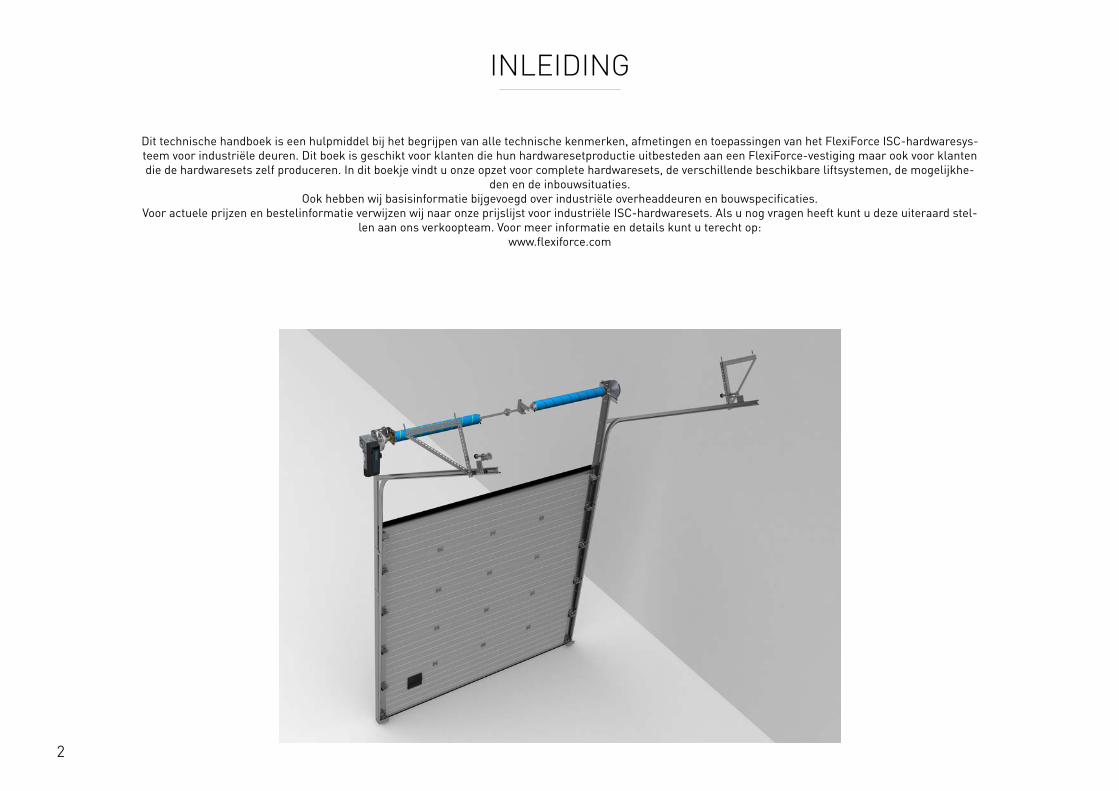
2
INLEIDING
Dit technische handboek is een hulpmiddel bij het begrijpen van alle technische kenmerken, afmetingen en toepassingen van het FlexiForce ISC-hardwaresys-teem voor industriële deuren. Dit boek is geschikt voor klanten die hun hardwaresetproductie uitbesteden aan een FlexiForce-vestiging maar ook voor klanten die de hardwaresets zelf produceren. In dit boekje vindt u onze opzet voor complete hardwaresets, de verschillende beschikbare liftsystemen, de mogelijkhe-
den en de inbouwsituaties. Ook hebben wij basisinformatie bijgevoegd over industriële overheaddeuren en bouwspecificaties.
Voor actuele prijzen en bestelinformatie verwijzen wij naar onze prijslijst voor industriële ISC-hardwaresets. Als u nog vragen heeft kunt u deze uiteraard stel-len aan ons verkoopteam. Voor meer informatie en details kunt u terecht op:
www.flexiforce.com
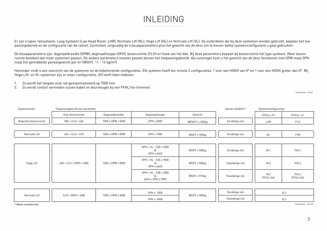
3
INLEIDING
Er zijn 4 typen railsysteem: Laag Systeem (Low Head Room, LHR), Normale Lift (NL), Hoge Lift (HL) en Verticale Lift (VL). De onderdelen die bij deze systemen worden gebruikt, bepalen het toe-passingsbereik en de configuratie van de railset. Controleer zorgvuldig de 4 bouwparameters plus het gewicht van de deur om te kiezen welke systeemconfiguratie u gaat gebruiken. De bouwparameters zijn: dagmaatbreedte (OPW), dagmaathoogte (OPH), bovenruimte (CLH) en hoek van het dak. Bij deze parameters bepaalt de bovenruimte het type systeem. Meer boven-ruimte betekent dat meer systemen passen. De andere parameters moeten passen binnen het toepassingsbereik. Als vuistregel kunt u het gewicht van de deur berekenen met OPW maal OPH maal het gemiddelde paneelgewicht per m² (WGHT: 11 - 12 kg/m²). Hieronder vindt u een overzicht van de systemen en de bijbehorende configuraties. Elk systeem heeft ten minste 2 configuraties, 1 voor een HOEK van 0° en 1 voor een HOEK groter dan 0°. Bij Hoge Lift- en VL-systemen zijn er meer configuraties. Dit heeft twee redenen: 1. Zo wordt het langste stuk rail gemaximaliseerd op 7000 mm 2. Zo wordt contact vermeden tussen kabel en deurvleugel bij een FFHL164-trommel.
Introduction - A1:A2
Systeemnaam Toepassingsbereik per parameter Aantal raildelen* Systeemconfiguraties
Vrije bovenruimte Dagmaatbreedte Dagmaathoogte Gewicht PITCH = 0° PITCH > 0°
Beperkte bovenruimte 200 < CLH < 436 1500 ≤ OPW ≤ 5000 OPH ≤ 5000 WEIGHT ≤ 400kg Eendelige rail LHR FLH
Normale Lift 436 < CLH < 518 1500 ≤ OPW ≤ 8500 OPH ≤ 7000 WGHT ≤ 700kg Eendelige rail NL FTR
Hoge Lift 438 < CLH < (OPH + 658) 1500 ≤ OPW ≤ 8500
OPH + HL - 528 ≤ 7000 &
OPH ≤ 6645WGHT ≤ 500kg Eendelige rail HL1 FHL1
OPH + HL - 528 ≥ 7000 &
OPH ≤ 6645WGHT ≤ 500kg Tweedelige rail HL2 FHL2
OPH + HL - 528 ≥ 7000 &
6645 ≤ OPH ≤ 7000WGHT ≤ 575kg Tweedelige rail HL2
(FFHL164)FHL2
(FFHL164)
Verticale Lift CLH > (OPH + 658) 1500 ≤ OPW ≤ 8500OPH ≤ 3300
WGHT ≤ 500kgEendelige rail VL1
OPH ≤ 6000 Tweedelige rail VL2
* Alleen verticale rails Introduction - A4:K17

4
Details systeem Min. Max.
Dagmaatbreedte OPW 1500mm 8500mm
Dagmaathoogte OPH 1830mm 7000mm
Bevestigingsbreedte S* 68mm 78mm
Ashoogte Y 350mm 391mm
Inbouwhoogte Z 436mm 518mm
Hoek PITCH - 0°
Afstand wand tot as HOH 111mm 127mm
Gewicht 700kg
Bovenwigmaat UWS Zie tabel
Bodemwigmaat BWS Zie tabel
* Afhankelijk van de keuze voor CBD of bodemconsoles, zie de pagina BodemconsolesRequirements & Technical Data - A2:D16
OPH
UWS
HOH
Y
BWS
Z
PIT
CH
OPH
OPW
≥S
≥125
≥10
00
≥80
*
Y Z
OPH - 210
= = = ≥250
12
3 48
This
wor
k is
cop
yrig
ht a
nd n
o pa
rt m
ay b
e re
prod
uced
, by
any
proc
ess,
nor
may
any
oth
er e
xclu
sive
righ
t be
exer
cise
d w
ithou
t the
per
mis
sion
of A
SSA
ABLO
Y.
Surface treatment:
V9_2
019_
02_2
1_dr
wRev.:Document ID
Material: General tolerance:
Volume: Mass: Surface area: Created (YYYY-MM-DD): Designed by: Drawn by: Scale: Projection:
Alternate ID289465723.43 mm³ 1:100 (A3)54462775.75 mm²289465.72 gram
ISO 8015ISO 2768-mH
1SHEET 1 OF 1Configuration:ISC-NL
Met een Normale Lift-systeem (NL) beweegt de deur door de bocht direct boven de deuropening (OPH, latei). Afhankelijk van de dagmaathoogte moet er een inbouwruimte tussen 436 mm en 518 mm beschikbaar zijn. Als er meer ruimte beschikbaar is, heeft het de voorkeur een Hoge Lift-systeem (HL)te selecteren.
Als er minder bovenruimte beschikbaar is, kan een Laag Systeem (LHR) worden geselecteerd.
ISC - NL
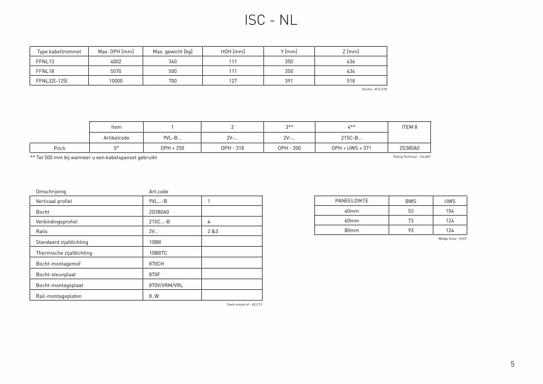
5
Details systeem Min. Max.
Dagmaatbreedte OPW 1500mm 8500mm
Dagmaathoogte OPH 1830mm 7000mm
Bevestigingsbreedte S* 68mm 78mm
Ashoogte Y 350mm 391mm
Inbouwhoogte Z 436mm 518mm
Hoek PITCH - 0°
Afstand wand tot as HOH 111mm 127mm
Gewicht 700kg
Bovenwigmaat UWS Zie tabel
Bodemwigmaat BWS Zie tabel
* Afhankelijk van de keuze voor CBD of bodemconsoles, zie de pagina BodemconsolesRequirements & Technical Data - A2:D16
Omschrijving Art.code
Verticaal profiel 9VL…-B 1
Bocht 2G380A0
Verbindingsprofiel 215C…-B 4
Rails 2V… 2 &3
Standaard zijafdichting 1088I
Thermische zijafdichting 1088ITC
Bocht-montagemof 870CH
Bocht-steunplaat 870F
Bocht-montageplaat 870V/VRM/VRL
Rail-montageplaten 8..WTrack consist of - A2:C13
Type kabeltrommel Max. OPH [mm] Max. gewicht [kg] HOH [mm] Y [mm] Z [mm]
FFNL13 4002 340 111 350 436
FFNL18 5570 500 111 350 436
FFNL32(-125) 10000 700 127 391 518Drums - B14:G18
Item 1 2 3** 4** ITEM 8
Artikelcode 9VL-B… 2V-… 2V-… 215C-B…
Pitch 0° OPH + 250 OPH - 318 OPH - 200 OPH + UWS + 371 2G380A0
** Tel 500 mm bij wanneer u een kabelspanset gebruikt Ruling Technical - U4:AA7
PANEELDIKTE BWS UWS
40mm 53 104
60mm 73 124
80mm 93 124Wedge Sizes - I3:K7
ISC - NL
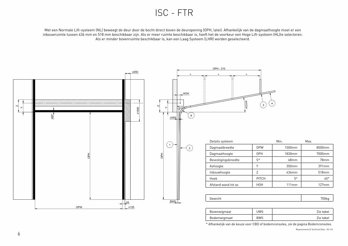
6
Details systeem Min. Max.
Dagmaatbreedte OPW 1500mm 8500mm
Dagmaathoogte OPH 1830mm 7000mm
Bevestigingsbreedte S* 68mm 78mm
Ashoogte Y 350mm 391mm
Inbouwhoogte Z 436mm 518mm
Hoek PITCH 5° 45°
Afstand wand tot as HOH 111mm 127mm
Gewicht 700kg
Bovenwigmaat UWS Zie tabel
Bodemwigmaat BWS Zie tabel
* Afhankelijk van de keuze voor CBD of bodemconsoles, zie de pagina BodemconsolesRequirements & Technical Data - G2:J16
OPH
UWS
HOH
Y
BWS
Z
PITCH
OPH
OPW
≥S
≥125
≥10
00
≥80
*
Y Z
OPH - 210
= = = ≥250
12
3 4
8
This
wor
k is
cop
yrig
ht a
nd n
o pa
rt m
ay b
e re
prod
uced
, by
any
proc
ess,
nor
may
any
oth
er e
xclu
sive
righ
t be
exer
cise
d w
ithou
t the
per
mis
sion
of A
SSA
ABLO
Y.
Surface treatment:
V9_2
019_
02_2
1_dr
wRev.:Document ID
Material: General tolerance:
Volume: Mass: Surface area: Created (YYYY-MM-DD): Designed by: Drawn by: Scale: Projection:
Alternate ID289310826.07 mm³ 1:100 (A3)54414606.92 mm²289310.83 gram
ISO 8015ISO 2768-mH
1SHEET 1 OF 1Configuration:ISC-FTR
Met een Normale Lift-systeem (NL) beweegt de deur door de bocht direct boven de deuropening (OPH, latei). Afhankelijk van de dagmaathoogte moet er een inbouwruimte tussen 436 mm en 518 mm beschikbaar zijn. Als er meer ruimte beschikbaar is, heeft het de voorkeur een Hoge Lift-systeem (HL)te selecteren.
Als er minder bovenruimte beschikbaar is, kan een Laag Systeem (LHR) worden geselecteerd.
ISC - FTR
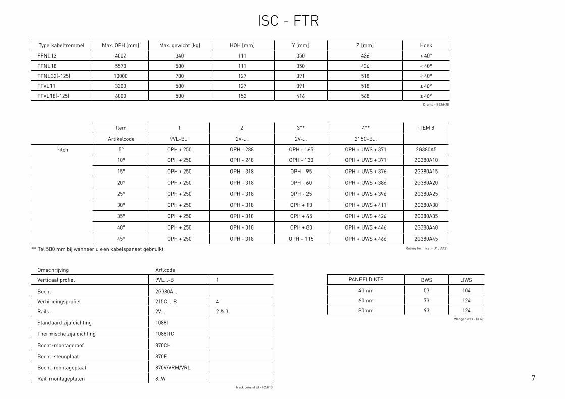
7
Omschrijving Art.code
Verticaal profiel 9VL…-B 1
Bocht 2G380A…
Verbindingsprofiel 215C…-B 4
Rails 2V… 2 & 3
Standaard zijafdichting 1088I
Thermische zijafdichting 1088ITC
Bocht-montagemof 870CH
Bocht-steunplaat 870F
Bocht-montageplaat 870V/VRM/VRL
Rail-montageplaten 8..WTrack consist of - F2:H13
Type kabeltrommel Max. OPH [mm] Max. gewicht [kg] HOH [mm] Y [mm] Z [mm] Hoek
FFNL13 4002 340 111 350 436 < 40°
FFNL18 5570 500 111 350 436 < 40°
FFNL32(-125) 10000 700 127 391 518 < 40°
FFVL11 3300 500 127 391 518 ≥ 40°
FFVL18(-125) 6000 500 152 416 568 ≥ 40°Drums - B22:H28
Item 1 2 3** 4** ITEM 8
Artikelcode 9VL-B… 2V-… 2V-… 215C-B…
Pitch 5° OPH + 250 OPH - 288 OPH - 165 OPH + UWS + 371 2G380A5
10° OPH + 250 OPH - 248 OPH - 130 OPH + UWS + 371 2G380A10
15° OPH + 250 OPH - 318 OPH - 95 OPH + UWS + 376 2G380A15
20° OPH + 250 OPH - 318 OPH - 60 OPH + UWS + 386 2G380A20
25° OPH + 250 OPH - 318 OPH - 25 OPH + UWS + 396 2G380A25
30° OPH + 250 OPH - 318 OPH + 10 OPH + UWS + 411 2G380A30
35° OPH + 250 OPH - 318 OPH + 45 OPH + UWS + 426 2G380A35
40° OPH + 250 OPH - 318 OPH + 80 OPH + UWS + 446 2G380A40
45° OPH + 250 OPH - 318 OPH + 115 OPH + UWS + 466 2G380A45
** Tel 500 mm bij wanneer u een kabelspanset gebruikt Ruling Technical - U10:AA21
PANEELDIKTE BWS UWS
40mm 53 104
60mm 73 124
80mm 93 124Wedge Sizes - I3:K7
ISC - FTR
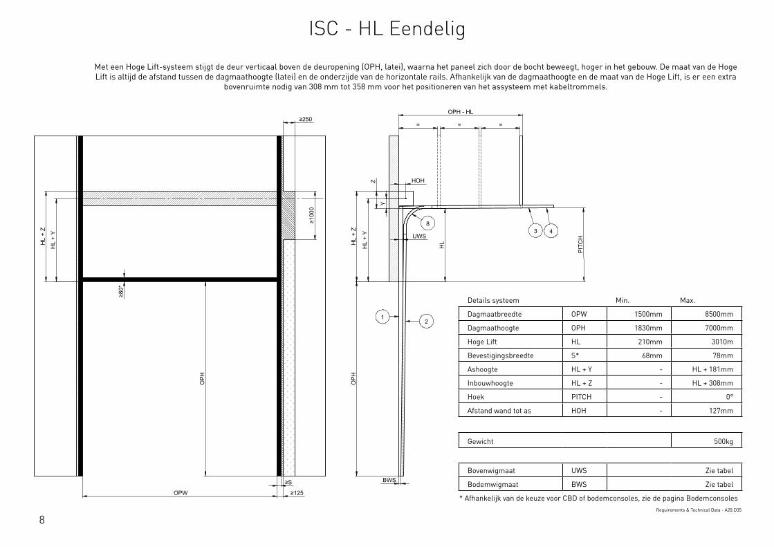
8
Details systeem Min. Max.
Dagmaatbreedte OPW 1500mm 8500mm
Dagmaathoogte OPH 1830mm 7000mm
Hoge Lift HL 210mm 3010m
Bevestigingsbreedte S* 68mm 78mm
Ashoogte HL + Y - HL + 181mm
Inbouwhoogte HL + Z - HL + 308mm
Hoek PITCH - 0°
Afstand wand tot as HOH - 127mm
Gewicht 500kg
Bovenwigmaat UWS Zie tabel
Bodemwigmaat BWS Zie tabel
* Afhankelijk van de keuze voor CBD of bodemconsoles, zie de pagina BodemconsolesRequirements & Technical Data - A20:D35
OPH
UWS
HOH
BWS
PIT
CH
OPH
OPW
≥S
≥125
≥10
00
≥80
*
HL
+ Y
HL
+ Z
OPH - HL
= = =
HL
Y
Z
≥250
HL
+ Y
HL
+ Z
12
3 48
This
wor
k is
cop
yrig
ht a
nd n
o pa
rt m
ay b
e re
prod
uced
, by
any
proc
ess,
nor
may
any
oth
er e
xclu
sive
righ
t be
exer
cise
d w
ithou
t the
per
mis
sion
of A
SSA
ABLO
Y.
Surface treatment:
V9_2
019_
02_2
1_dr
wRev.:Document ID
Material: General tolerance:
Volume: Mass: Surface area: Created (YYYY-MM-DD): Designed by: Drawn by: Scale: Projection:
Alternate ID415397163.98 mm³ 1:100 (A3)74737484.21 mm²415397.16 gram
ISO 8015ISO 2768-mH
1SHEET 1 OF 1Configuration:ISC-HL-1Piece
Met een Hoge Lift-systeem stijgt de deur verticaal boven de deuropening (OPH, latei), waarna het paneel zich door de bocht beweegt, hoger in het gebouw. De maat van de Hoge Lift is altijd de afstand tussen de dagmaathoogte (latei) en de onderzijde van de horizontale rails. Afhankelijk van de dagmaathoogte en de maat van de Hoge Lift, is er een extra
bovenruimte nodig van 308 mm tot 358 mm voor het positioneren van het assysteem met kabeltrommels.
ISC - HL Eendelig
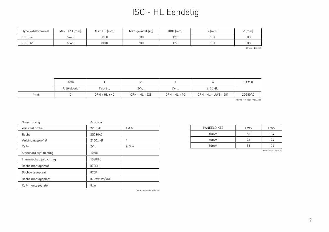
9
Omschrijving Art.code
Verticaal profiel 9VL…-B 1 & 5
Bocht 2G380A0
Verbindingsprofiel 215C…-B 4
Rails 2V… 2, 3, 6
Standaard zijafdichting 1088I
Thermische zijafdichting 1088ITC
Bocht-montagemof 870CH
Bocht-steunplaat 870F
Bocht-montageplaat 870V/VRM/VRL
Rail-montageplaten 8..WTrack consist of - A17:C28
Type kabeltrommel Max. OPH [mm] Max. HL [mm] Max. gewicht [kg] HOH [mm] Y [mm] Z [mm]
FFHL54 5945 1380 500 127 181 308
FFHL120 6645 3010 500 127 181 308Drums - B32:H35
Item 1 2 3 4 ITEM 8
Artikelcode 9VL-B… 2V-… 2V-… 215C-B…
Pitch 0 OPH + HL + 40 OPH + HL - 528 OPH - HL + 10 OPH - HL + UWS + 581 2G380A0Ruling Technical - U25:AA28
PANEELDIKTE BWS UWS
40mm 53 104
60mm 73 124
80mm 93 124Wedge Sizes - I10:K14
ISC - HL Eendelig

10
Details systeem Min. Max.
Dagmaatbreedte OPW 1500mm 8500mm
Dagmaathoogte OPH 1830mm 7000mm
Hoge Lift HL 210mm 3010mm
Bevestigingsbreedte S* 68mm 78mm
Ashoogte HL + Y HL + 181mm HL + 206mm
Inbouwhoogte HL + Z HL + 308mm HL + 358mm
Hoek PITCH 5° 45°
Afstand wand tot as HOH - 127mm
Gewicht 500kg
Bovenwigmaat UWS Zie tabel
Bodemwigmaat BWS Zie tabel
* Afhankelijk van de keuze voor CBD of bodemconsoles, zie de pagina BodemconsolesRequirements & Technical Data - G20:J35
OPH
UWS
HOH
HL
+ Y
BWS
HL
+ Z
PITCH
O
PH
OPW ≥S ≥125
≥10
00
≥80
*
HL
+ Y
HL
+ Z
OPH - HL
= = =
HL
Z
Y
≥250
12
3 4
8
This
wor
k is
cop
yrig
ht a
nd n
o pa
rt m
ay b
e re
prod
uced
, by
any
proc
ess,
nor
may
any
oth
er e
xclu
sive
righ
t be
exer
cise
d w
ithou
t the
per
mis
sion
of A
SSA
ABLO
Y.
Surface treatment:
V9_2
019_
02_2
1_dr
wRev.:Document ID
Material: General tolerance:
Volume: Mass: Surface area: Created (YYYY-MM-DD): Designed by: Drawn by: Scale: Projection:
Alternate ID415364243.14 mm³ 1:100 (A3)74721651.39 mm²415364.24 gram
ISO 8015ISO 2768-mH
1SHEET 1 OF 1Configuration:ISC-FHL-1Piece
Met een Hoge Lift-systeem stijgt de deur verticaal boven de deuropening (OPH, latei), waarna het paneel zich door de bocht beweegt, hoger in het gebouw. De maat van de Hoge Lift is altijd de afstand tussen de dagmaathoogte (latei) en de onderzijde van de horizontale rails. Afhankelijk van de dagmaathoogte en de
maat van de Hoge Lift, is er een extra bovenruimte nodig van 308 mm tot 358 mm voor het positioneren van het assysteem met kabeltrommels.
ISC - FHL Eendelig
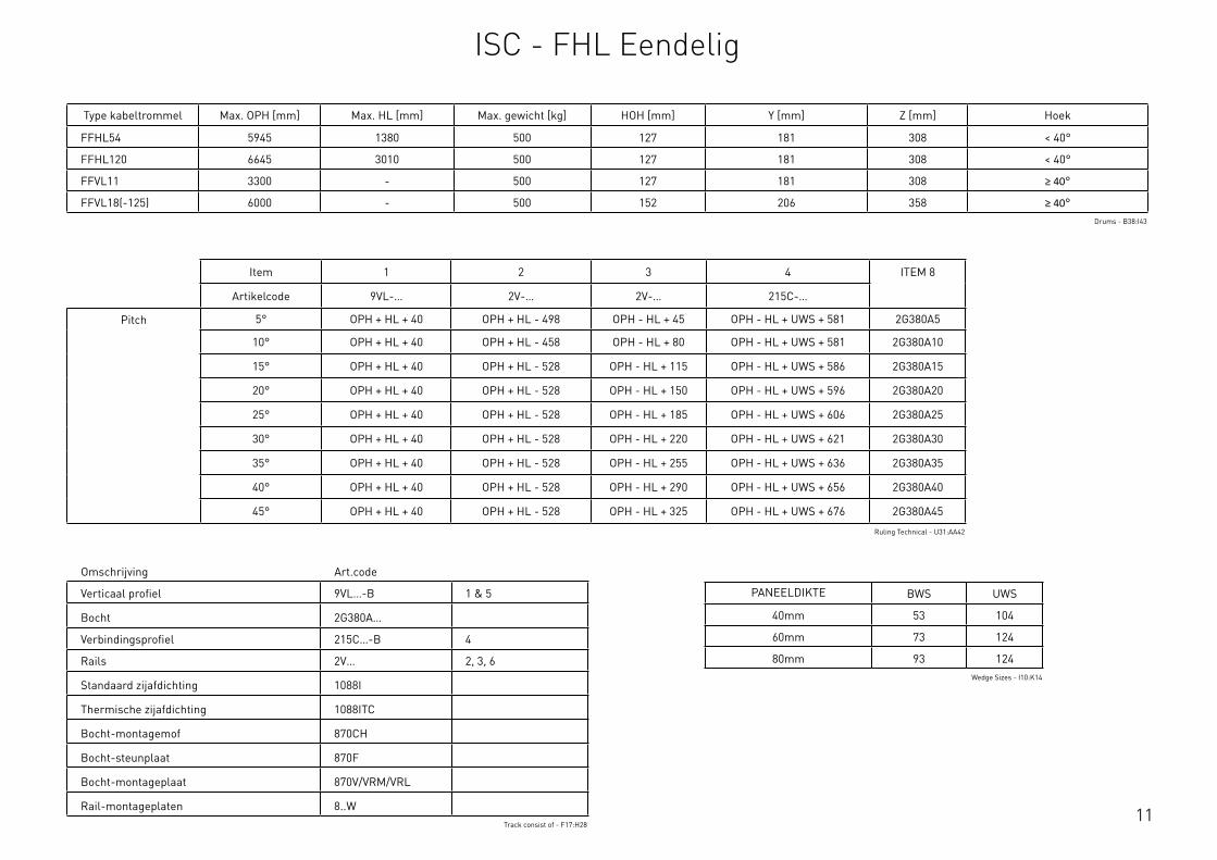
11
Omschrijving Art.code
Verticaal profiel 9VL…-B 1 & 5
Bocht 2G380A…
Verbindingsprofiel 215C…-B 4
Rails 2V… 2, 3, 6
Standaard zijafdichting 1088I
Thermische zijafdichting 1088ITC
Bocht-montagemof 870CH
Bocht-steunplaat 870F
Bocht-montageplaat 870V/VRM/VRL
Rail-montageplaten 8..WTrack consist of - F17:H28
Type kabeltrommel Max. OPH [mm] Max. HL [mm] Max. gewicht [kg] HOH [mm] Y [mm] Z [mm] Hoek
FFHL54 5945 1380 500 127 181 308 < 40°
FFHL120 6645 3010 500 127 181 308 < 40°
FFVL11 3300 - 500 127 181 308 ≥ 40°
FFVL18(-125) 6000 - 500 152 206 358 ≥ 40°Drums - B38:I43
Item 1 2 3 4 ITEM 8
Artikelcode 9VL-… 2V-… 2V-… 215C-…
Pitch 5° OPH + HL + 40 OPH + HL - 498 OPH - HL + 45 OPH - HL + UWS + 581 2G380A5
10° OPH + HL + 40 OPH + HL - 458 OPH - HL + 80 OPH - HL + UWS + 581 2G380A10
15° OPH + HL + 40 OPH + HL - 528 OPH - HL + 115 OPH - HL + UWS + 586 2G380A15
20° OPH + HL + 40 OPH + HL - 528 OPH - HL + 150 OPH - HL + UWS + 596 2G380A20
25° OPH + HL + 40 OPH + HL - 528 OPH - HL + 185 OPH - HL + UWS + 606 2G380A25
30° OPH + HL + 40 OPH + HL - 528 OPH - HL + 220 OPH - HL + UWS + 621 2G380A30
35° OPH + HL + 40 OPH + HL - 528 OPH - HL + 255 OPH - HL + UWS + 636 2G380A35
40° OPH + HL + 40 OPH + HL - 528 OPH - HL + 290 OPH - HL + UWS + 656 2G380A40
45° OPH + HL + 40 OPH + HL - 528 OPH - HL + 325 OPH - HL + UWS + 676 2G380A45
Ruling Technical - U31:AA42
PANEELDIKTE BWS UWS
40mm 53 104
60mm 73 124
80mm 93 124Wedge Sizes - I10:K14
ISC - FHL Eendelig

12
Dagmaatbreedte OPW 1500mm 8500mm
Dagmaathoogte OPH 1830mm 6645mm
Hoge Lift HL 210mm 3010mm
Bevestigingsbreedte S* 68mm 78mm
Ashoogte HL + Y - HL + 181mm
Inbouwhoogte HL + Z - HL + 308mm
Hoek PITCH - 0°
Afstand wand tot as HOH - 127mm
Gewicht 500kg
Bovenwigmaat UWS Zie tabel
Bodemwigmaat BWS Zie tabel
Variabele-wigmaat VWS Zie tabel
* Afhankelijk van de keuze voor CBD of bodemconsoles, zie de pagina BodemconsolesRequirements & Technical Data - A40:D55
OPH
UWS
HOH
HL
+ Y
BWS
HL
+ Z
PIT
CH
OPH
OPW
≥S
≥125
≥10
00
≥80
*
HL
+ Y
HL
+ Z
OPH - HL
= = =
HL
Y
Z
≥250
2
3 48
1
65
This
wor
k is
cop
yrig
ht a
nd n
o pa
rt m
ay b
e re
prod
uced
, by
any
proc
ess,
nor
may
any
oth
er e
xclu
sive
righ
t be
exer
cise
d w
ithou
t the
per
mis
sion
of A
SSA
ABLO
Y.
Surface treatment:
V9_2
019_
02_2
1_dr
wRev.:Document ID
Material: General tolerance:
Volume: Mass: Surface area: Created (YYYY-MM-DD): Designed by: Drawn by: Scale: Projection:
Alternate ID488235193.04 mm³ 1:100 (A3)89835498.33 mm²488235.19 gram
ISO 8015ISO 2768-mH
1SHEET 1 OF 1Configuration:ISC-HL-2Piece
Met een Hoge Lift-systeem stijgt de deur verticaal boven de deuropening (OPH, latei), waarna het paneel zich door de bocht beweegt, hoger in het gebouw. De maat van de Hoge Lift is altijd de afstand tussen de dagmaathoogte (latei) en de onderzijde van de horizontale rails. Afhankelijk van de dagmaathoogte en de
maat van de Hoge Lift, is er een extra bovenruimte nodig van 308 mm tot 358 mm voor het positioneren van het assysteem met kabeltrommels.
ISC - HL Tweedelig

13
Omschrijving Art.code
Verticaal profiel 9VL…-B 1 & 5
Bocht 2G380A0
Verbindingsprofiel 215C…-B 4
Rails 2V… 2, 3, 6
Standaard zijafdichting 1088I
Thermische zijafdichting 1088ITC
Bocht-montagemof 870CH
Bocht-steunplaat 870F
Bocht-montageplaat 870V/VRM/VRL
Rail-montageplaten 8..WTrack consist of - A17:C28
Type kabeltrommel Max. OPH [mm] Max. HL [mm] Max. gewicht [kg] HOH [mm] Y [mm] Z [mm]
FFHL54 5945 1380 500 127 181 308
FFHL120 6645 3010 500 127 181 308Drums - B32:H35
Item 1 2 3 4 5 6
Artikelcode 9VL-B… 2V-… 2V-… 215C-B… 9VL-B… 2V-…
Pitch 0° 6100 6098 OPH - HL + 10 OPH - HL + UWS + 581 OPH + HL - 6060 OPH + HL - 6626Ruling Technical - U46:AB49
PANEELDIKTE BWS VWS UWS
40mm 53 114 VWS + (L6/100)
60mm 73 134 VWS + (L6/100)
80mm 93 134 VWS + (L6/100)Wedge Sizes - I17:L21
ISC - HL Tweedelig
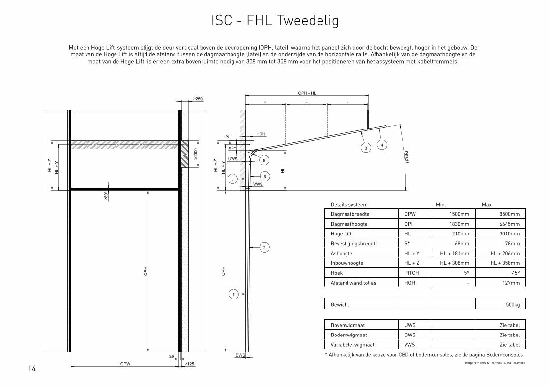
14
Details systeem Min. Max.
Dagmaatbreedte OPW 1500mm 8500mm
Dagmaathoogte OPH 1830mm 6645mm
Hoge Lift HL 210mm 3010mm
Bevestigingsbreedte S* 68mm 78mm
Ashoogte HL + Y HL + 181mm HL + 206mm
Inbouwhoogte HL + Z HL + 308mm HL + 358mm
Hoek PITCH 5° 45°
Afstand wand tot as HOH - 127mm
Gewicht 500kg
Bovenwigmaat UWS Zie tabel
Bodemwigmaat BWS Zie tabel
Variabele-wigmaat VWS Zie tabel
* Afhankelijk van de keuze voor CBD of bodemconsoles, zie de pagina BodemconsolesRequirements & Technical Data - G39:J55
OPH
UWS
HOH
HL
+ Y
BWS
HL
+ Z
PITCH
O
PH
OPW
≥S
≥125
≥10
00
≥80
*
HL
+ Y
HL
+ Z
OPH - HL
= = =
HL
VWS
Z
Y
≥250
2
34
8
1
65
This
wor
k is
cop
yrig
ht a
nd n
o pa
rt m
ay b
e re
prod
uced
, by
any
proc
ess,
nor
may
any
oth
er e
xclu
sive
righ
t be
exer
cise
d w
ithou
t the
per
mis
sion
of A
SSA
ABLO
Y.
Surface treatment:
V9_2
019_
02_2
1_dr
wRev.:Document ID
Material: General tolerance:
Volume: Mass: Surface area: Created (YYYY-MM-DD): Designed by: Drawn by: Scale: Projection:
Alternate ID488036705.35 mm³ 1:100 (A3)89774518.55 mm²488036.71 gram
ISO 8015ISO 2768-mH
1SHEET 1 OF 1Configuration:ISC-FHL-2Piece
Met een Hoge Lift-systeem stijgt de deur verticaal boven de deuropening (OPH, latei), waarna het paneel zich door de bocht beweegt, hoger in het gebouw. De maat van de Hoge Lift is altijd de afstand tussen de dagmaathoogte (latei) en de onderzijde van de horizontale rails. Afhankelijk van de dagmaathoogte en de
maat van de Hoge Lift, is er een extra bovenruimte nodig van 308 mm tot 358 mm voor het positioneren van het assysteem met kabeltrommels.
ISC - FHL Tweedelig

15
Omschrijving Art.code
Verticaal profiel 9VL…-B 1 & 5
Bocht 2G380A…
Verbindingsprofiel 215C…-B 4
Rails 2V… 2, 3, 6
Standaard zijafdichting 1088I
Thermische zijafdichting 1088ITC
Bocht-montagemof 870CH
Bocht-steunplaat 870F
Bocht-montageplaat 870V/VRM/VRL
Rail-montageplaten 8..WTrack consist of - F17:H28
Type kabeltrommel Max. OPH [mm] Max. HL [mm] Max. gewicht [kg] HOH [mm] Y [mm] Z [mm] Hoek
FFHL54 5945 1380 500 127 181 308 < 40°
FFHL120 6645 3010 500 127 181 308 < 40°
FFVL11 3300 - 500 127 181 308 ≥ 40°
FFVL18(-125) 6000 - 500 152 206 358 ≥ 40°Drums - B38:I43
Item 1 2 3 4 5 6
Artikelcode 9VL-B… 2V-… 2V-… 215C-B… 9VL-B… 2V-…
Pitch 5° 6100 6098 OPH - HL + 45 OPH - HL + UWS + 581 OPH + HL - 6060 OPH + HL - 6656
10° 6100 6098 OPH - HL + 80 OPH - HL + UWS + 581 OPH + HL - 6060 OPH + HL - 6696
15° 6100 6098 OPH - HL + 115 OPH - HL + UWS + 586 OPH + HL - 6060 OPH + HL - 6626
20° 6100 6098 OPH - HL + 150 OPH - HL + UWS + 596 OPH + HL - 6060 OPH + HL - 6626
25° 6100 6098 OPH - HL + 185 OPH - HL + UWS + 606 OPH + HL - 6060 OPH + HL - 6626
30° 6100 6098 OPH - HL + 220 OPH - HL + UWS + 621 OPH + HL - 6060 OPH + HL - 6626
35° 6100 6098 OPH - HL + 255 OPH - HL + UWS + 636 OPH + HL - 6060 OPH + HL - 6626
40° 6100 6098 OPH - HL + 290 OPH - HL + UWS + 656 OPH + HL - 6060 OPH + HL - 6626
45° 6100 6098 OPH - HL + 325 OPH - HL + UWS + 676 OPH + HL - 6060 OPH + HL - 6626
Ruling Technical - U52:AB63
PANEELDIKTE BWS VWS UWS
40mm 53 114 VWS + (L6/100)
60mm 73 134 VWS + (L6/100)
80mm 93 134 VWS + (L6/100)Wedge Sizes - I17:L21
ISC - FHL Tweedelig
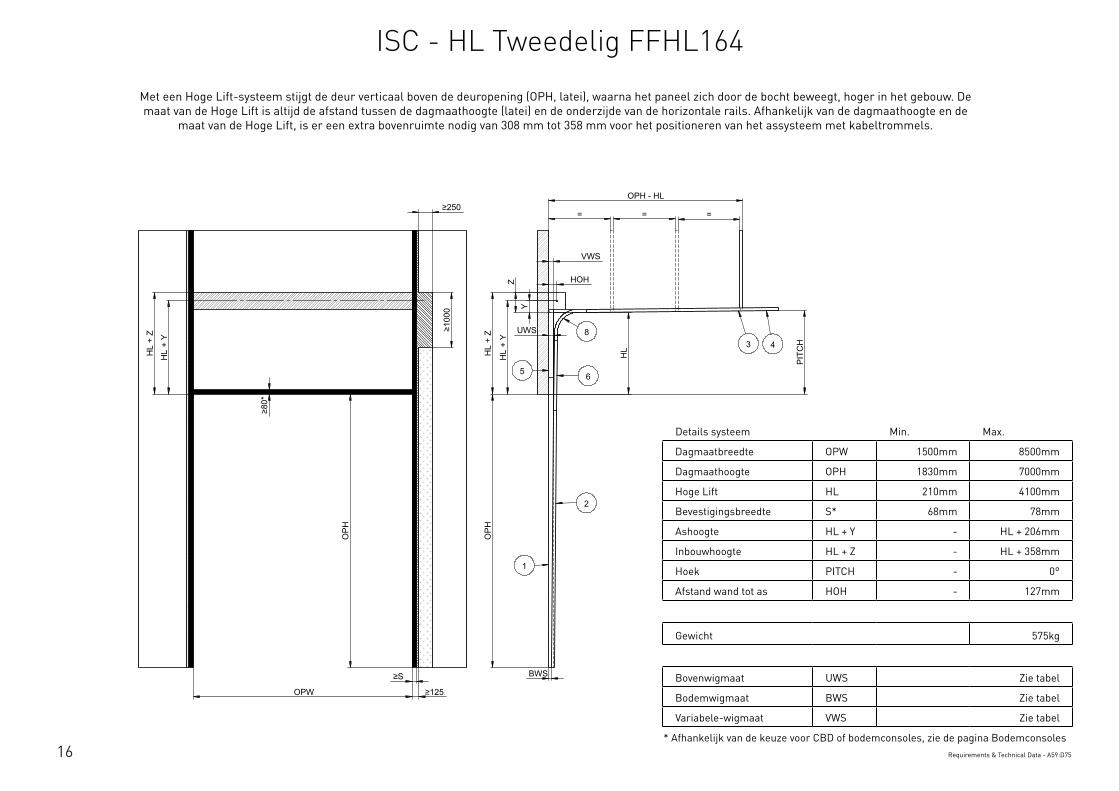
16
Details systeem Min. Max.
Dagmaatbreedte OPW 1500mm 8500mm
Dagmaathoogte OPH 1830mm 7000mm
Hoge Lift HL 210mm 4100mm
Bevestigingsbreedte S* 68mm 78mm
Ashoogte HL + Y - HL + 206mm
Inbouwhoogte HL + Z - HL + 358mm
Hoek PITCH - 0°
Afstand wand tot as HOH - 127mm
Gewicht 575kg
Bovenwigmaat UWS Zie tabel
Bodemwigmaat BWS Zie tabel
Variabele-wigmaat VWS Zie tabel
* Afhankelijk van de keuze voor CBD of bodemconsoles, zie de pagina BodemconsolesRequirements & Technical Data - A59:D75
OPH
UWS
HOH
HL
+ Y
BWS
HL
+ Z
PIT
CH
OPH
OPW
≥S
≥125
≥10
00
≥80
*
HL
+ Y
HL
+ Z
OPH - HL
= = =
HL
VWS
Y
Z
≥250
2
3 48
1
65
This
wor
k is
cop
yrig
ht a
nd n
o pa
rt m
ay b
e re
prod
uced
, by
any
proc
ess,
nor
may
any
oth
er e
xclu
sive
righ
t be
exer
cise
d w
ithou
t the
per
mis
sion
of A
SSA
ABLO
Y.
Surface treatment:
V9_2
019_
02_2
1_dr
wRev.:Document ID
Material: General tolerance:
Volume: Mass: Surface area: Created (YYYY-MM-DD): Designed by: Drawn by: Scale: Projection:
Alternate ID450571832.56 mm³ 1:100 (A3)82034869.87 mm²450571.83 gram
ISO 8015ISO 2768-mH
1SHEET 1 OF 1Configuration:ISC-HL-FFHL164-2Piece
Met een Hoge Lift-systeem stijgt de deur verticaal boven de deuropening (OPH, latei), waarna het paneel zich door de bocht beweegt, hoger in het gebouw. De maat van de Hoge Lift is altijd de afstand tussen de dagmaathoogte (latei) en de onderzijde van de horizontale rails. Afhankelijk van de dagmaathoogte en de
maat van de Hoge Lift, is er een extra bovenruimte nodig van 308 mm tot 358 mm voor het positioneren van het assysteem met kabeltrommels.
ISC - HL Tweedelig FFHL164
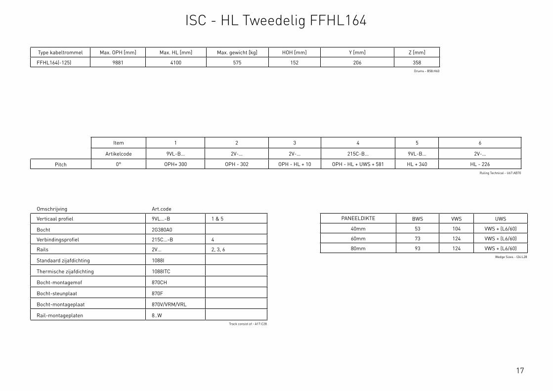
17
Omschrijving Art.code
Verticaal profiel 9VL…-B 1 & 5
Bocht 2G380A0
Verbindingsprofiel 215C…-B 4
Rails 2V… 2, 3, 6
Standaard zijafdichting 1088I
Thermische zijafdichting 1088ITC
Bocht-montagemof 870CH
Bocht-steunplaat 870F
Bocht-montageplaat 870V/VRM/VRL
Rail-montageplaten 8..WTrack consist of - A17:C28
Type kabeltrommel Max. OPH [mm] Max. HL [mm] Max. gewicht [kg] HOH [mm] Y [mm] Z [mm]
FFHL164(-125) 9881 4100 575 152 206 358Drums - B58:H60
Item 1 2 3 4 5 6
Artikelcode 9VL-B… 2V-… 2V-… 215C-B… 9VL-B… 2V-…
Pitch 0° OPH+ 300 OPH - 302 OPH - HL + 10 OPH - HL + UWS + 581 HL + 340 HL - 226Ruling Technical - U67:AB70
PANEELDIKTE BWS VWS UWS
40mm 53 104 VWS + (L6/60)
60mm 73 124 VWS + (L6/60)
80mm 93 124 VWS + (L6/60)Wedge Sizes - I24:L28
ISC - HL Tweedelig FFHL164
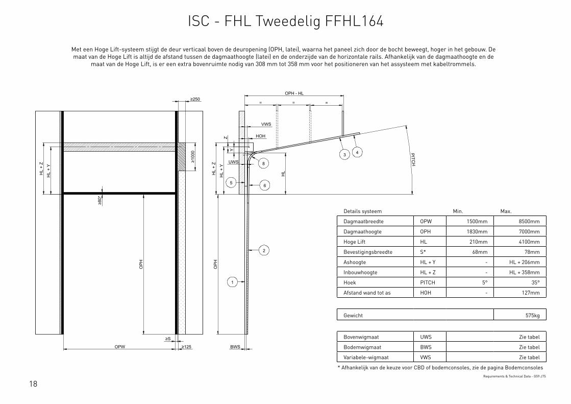
18
Details systeem Min. Max.
Dagmaatbreedte OPW 1500mm 8500mm
Dagmaathoogte OPH 1830mm 7000mm
Hoge Lift HL 210mm 4100mm
Bevestigingsbreedte S* 68mm 78mm
Ashoogte HL + Y - HL + 206mm
Inbouwhoogte HL + Z - HL + 358mm
Hoek PITCH 5° 35°
Afstand wand tot as HOH - 127mm
Gewicht 575kg
Bovenwigmaat UWS Zie tabel
Bodemwigmaat BWS Zie tabel
Variabele-wigmaat VWS Zie tabel
* Afhankelijk van de keuze voor CBD of bodemconsoles, zie de pagina BodemconsolesRequirements & Technical Data - G59:J75
OPH
UWS
HOH
HL
+ Y
BWS
HL
+ Z
PITCH
OPH
OPW
≥S
≥125
≥10
00
≥80
*
HL
+ Y
HL
+ Z
OPH - HL
= = =
HL
VWS
Z
Y
≥250
2
3 4
8
1
65
This
wor
k is
cop
yrig
ht a
nd n
o pa
rt m
ay b
e re
prod
uced
, by
any
proc
ess,
nor
may
any
oth
er e
xclu
sive
righ
t be
exer
cise
d w
ithou
t the
per
mis
sion
of A
SSA
ABLO
Y.
Surface treatment:
V9_2
019_
02_2
1_dr
wRev.:Document ID
Material: General tolerance:
Volume: Mass: Surface area: Created (YYYY-MM-DD): Designed by: Drawn by: Scale: Projection:
Alternate ID450101481.54 mm³ 1:100 (A3)81922696.8 mm²450101.48 gram
ISO 8015ISO 2768-mH
1SHEET 1 OF 1Configuration:ISC-FHL-FFHL164-2Piece
Met een Hoge Lift-systeem stijgt de deur verticaal boven de deuropening (OPH, latei), waarna het paneel zich door de bocht beweegt, hoger in het gebouw. De maat van de Hoge Lift is altijd de afstand tussen de dagmaathoogte (latei) en de onderzijde van de horizontale rails. Afhankelijk van de dagmaathoogte en de
maat van de Hoge Lift, is er een extra bovenruimte nodig van 308 mm tot 358 mm voor het positioneren van het assysteem met kabeltrommels.
ISC - FHL Tweedelig FFHL164

19
Omschrijving Art.code
Verticaal profiel 9VL…-B 1 & 5
Bocht 2G380A…
Verbindingsprofiel 215C…-B 4
Rails 2V… 2, 3, 6
Standaard zijafdichting 1088I
Thermische zijafdichting 1088ITC
Bocht-montagemof 870CH
Bocht-steunplaat 870F
Bocht-montageplaat 870V/VRM/VRL
Rail-montageplaten 8..WTrack consist of - F17:H28
Type kabeltrommel Max. OPH [mm] Max. HL [mm] Max. gewicht [kg] HOH [mm] Y [mm] Z [mm] Hoek
FFHL164(-125) 9881 4100 575 152 206 358 < 40°Drums - B63:I65
Item 1 2 3 4 5 6
Artikelcode 9VL-B… 2V-… 2V-… 215C-B… 9VL-B… 2V-…
Pitch 5° OPH+ 300 OPH - 302 OPH - HL + 45 OPH - HL + UWS + 581 HL + 340 HL - 196
10° OPH+ 300 OPH - 302 OPH - HL + 80 OPH - HL + UWS + 581 HL + 340 HL - 156
15° OPH+ 300 OPH - 302 OPH - HL + 115 OPH - HL + UWS + 586 HL + 340 HL - 226
20° OPH+ 300 OPH - 302 OPH - HL + 150 OPH - HL + UWS + 596 HL + 340 HL - 226
25° OPH+ 300 OPH - 302 OPH - HL + 185 OPH - HL + UWS + 606 HL + 340 HL - 226
30° OPH+ 300 OPH - 302 OPH - HL + 220 OPH - HL + UWS + 621 HL + 340 HL - 226
35° OPH+ 300 OPH - 302 OPH - HL + 255 OPH - HL + UWS + 636 HL + 340 HL - 226
40° OPH+ 300 OPH - 302 OPH - HL + 290 OPH - HL + UWS + 656 HL + 340 HL - 226
45° OPH+ 300 OPH - 302 OPH - HL + 325 OPH - HL + UWS + 676 HL + 340 HL - 226
Ruling Technical - U73:AB84
PANEELDIKTE BWS VWS UWS
40mm 53 104 VWS + (L6/60)
60mm 73 124 VWS + (L6/60)
80mm 93 124 VWS + (L6/60)Wedge Sizes - I24:L28
ISC - FHL Tweedelig FFHL164

20
Details systeem Min. Max.
Dagmaatbreedte OPW 1500mm 8500mm
Dagmaathoogte OPH 1830mm 3300mm
Bevestigingsbreedte S* 68mm 78mm
Ashoogte Y 127mm 152mm
Inbouwhoogte Z 254mm 304mm
Bovenwigmaat UWS Zie tabel
Bodemwigmaat BWS Zie tabel
Gewicht 500kg
* Afhankelijk van de keuze voor CBD of bodemconsoles, zie de pagina BodemconsolesRequirements & Technical Data - A79:D91
OPH
HOH
Y
BWS
Z
OPH
OPW ≥S ≥125
≥80
≥250
≥10
00
UWS
(2 x
OPH
) + 3
00
(2 x
OPH
) + 3
00 +
Y
(2 x
OPH
) + 3
00 +
Z 2
1
This
wor
k is
cop
yrig
ht a
nd n
o pa
rt m
ay b
e re
prod
uced
, by
any
proc
ess,
nor
may
any
oth
er e
xclu
sive
righ
t be
exer
cise
d w
ithou
t the
per
mis
sion
of A
SSA
ABLO
Y.
Surface treatment:
V9_2
019_
02_2
1_dr
wRev.:Document ID
Material: General tolerance:
Volume: Mass: Surface area: Created (YYYY-MM-DD): Designed by: Drawn by: Scale: Projection:
Alternate ID531320092.93 mm³ 1:100 (A3)90915516.55 mm²531320.09 gram
ISO 8015ISO 2768-mH
1SHEET 1 OF 1Configuration:ISC-VL-1Piece
Met een Verticale Lift-systeem beweegt de deur recht omhoog vanaf de deuropening (OPH, latei), wat betekent dat er voldoende bovenruimte beschikbaar moet zijn voor ten minste de hele deurhoogte. Het systeem heeft geen bocht. Bij Verticale Lift-systemen hangt het volledige deurgewicht in de hefkabels, in iedere
stand van de deur.
ISC - VL Eendelig
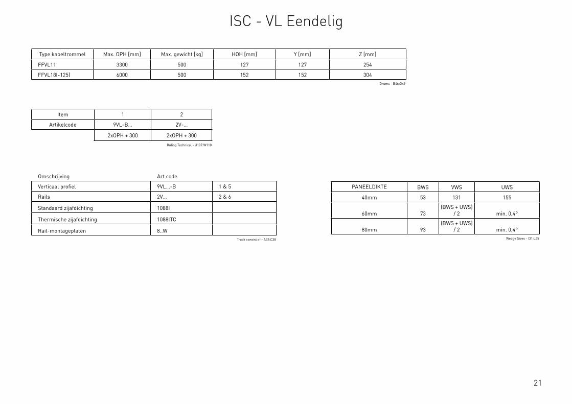
21
Omschrijving Art.code
Verticaal profiel 9VL…-B 1 & 5
Rails 2V… 2 & 6
Standaard zijafdichting 1088I
Thermische zijafdichting 1088ITC
Rail-montageplaten 8..WTrack consist of - A32:C38
Type kabeltrommel Max. OPH [mm] Max. gewicht [kg] HOH [mm] Y [mm] Z [mm]
FFVL11 3300 500 127 127 254
FFVL18(-125) 6000 500 152 152 304Drums - B46:G49
Item 1 2
Artikelcode 9VL-B… 2V-…
2xOPH + 300 2xOPH + 300
Ruling Technical - U107:W110
PANEELDIKTE BWS VWS UWS
40mm 53 131 155
60mm 73(BWS + UWS)
/ 2 min. 0,4°
80mm 93(BWS + UWS)
/ 2 min. 0,4°Wedge Sizes - I31:L35
ISC - VL Eendelig
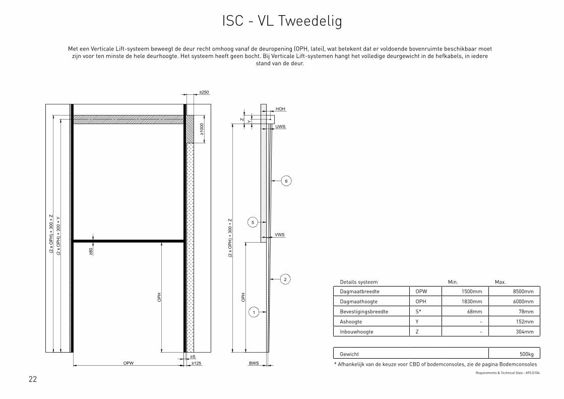
22
Details systeem Min. Max.
Dagmaatbreedte OPW 1500mm 8500mm
Dagmaathoogte OPH 1830mm 6000mm
Bevestigingsbreedte S* 68mm 78mm
Ashoogte Y - 152mm
Inbouwhoogte Z - 304mm
Gewicht 500kg
* Afhankelijk van de keuze voor CBD of bodemconsoles, zie de pagina BodemconsolesRequirements & Technical Data - A95:D104
OPH
HOH
Y
BWS
Z
OPH
OPW ≥S ≥125
≥80
≥250
≥10
00
UWS
VWS (2
x O
PH) +
300
+ Z
(2 x
OPH
) + 3
00 +
Y
(2 x
OPH
) + 3
00 +
Z
2
1
6
5
This
wor
k is
cop
yrig
ht a
nd n
o pa
rt m
ay b
e re
prod
uced
, by
any
proc
ess,
nor
may
any
oth
er e
xclu
sive
righ
t be
exer
cise
d w
ithou
t the
per
mis
sion
of A
SSA
ABLO
Y.
Surface treatment:
V9_2
019_
02_2
1_dr
wRev.:Document ID
Material: General tolerance:
Volume: Mass: Surface area: Created (YYYY-MM-DD): Designed by: Drawn by: Scale: Projection:
Alternate ID552648112.93 mm³ 1:100 (A3)95351980.55 mm²552648.11 gram
ISO 8015ISO 2768-mH
1SHEET 1 OF 1Configuration:ISC-VL-2Piece
Met een Verticale Lift-systeem beweegt de deur recht omhoog vanaf de deuropening (OPH, latei), wat betekent dat er voldoende bovenruimte beschikbaar moet zijn voor ten minste de hele deurhoogte. Het systeem heeft geen bocht. Bij Verticale Lift-systemen hangt het volledige deurgewicht in de hefkabels, in iedere
stand van de deur.
ISC - VL Tweedelig
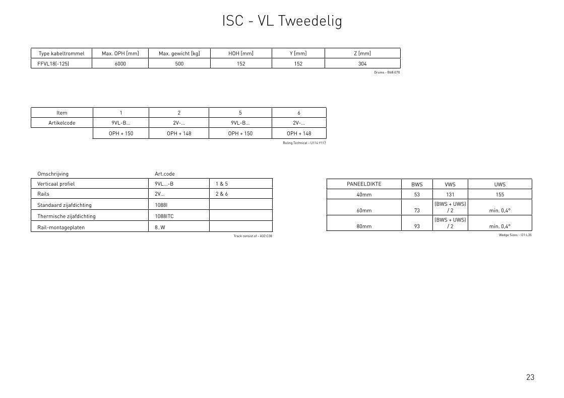
23
Omschrijving Art.code
Verticaal profiel 9VL…-B 1 & 5
Rails 2V… 2 & 6
Standaard zijafdichting 1088I
Thermische zijafdichting 1088ITC
Rail-montageplaten 8..WTrack consist of - A32:C38
Type kabeltrommel Max. OPH [mm] Max. gewicht [kg] HOH [mm] Y [mm] Z [mm]
FFVL18(-125) 6000 500 152 152 304Drums - B68:G70
Item 1 2 5 6
Artikelcode 9VL-B… 2V-… 9VL-B… 2V-…
OPH + 150 OPH + 148 OPH + 150 OPH + 148
Ruling Technical - U114:Y117
PANEELDIKTE BWS VWS UWS
40mm 53 131 155
60mm 73(BWS + UWS)
/ 2 min. 0,4°
80mm 93(BWS + UWS)
/ 2 min. 0,4°Wedge Sizes - I31:L35
ISC - VL Tweedelig
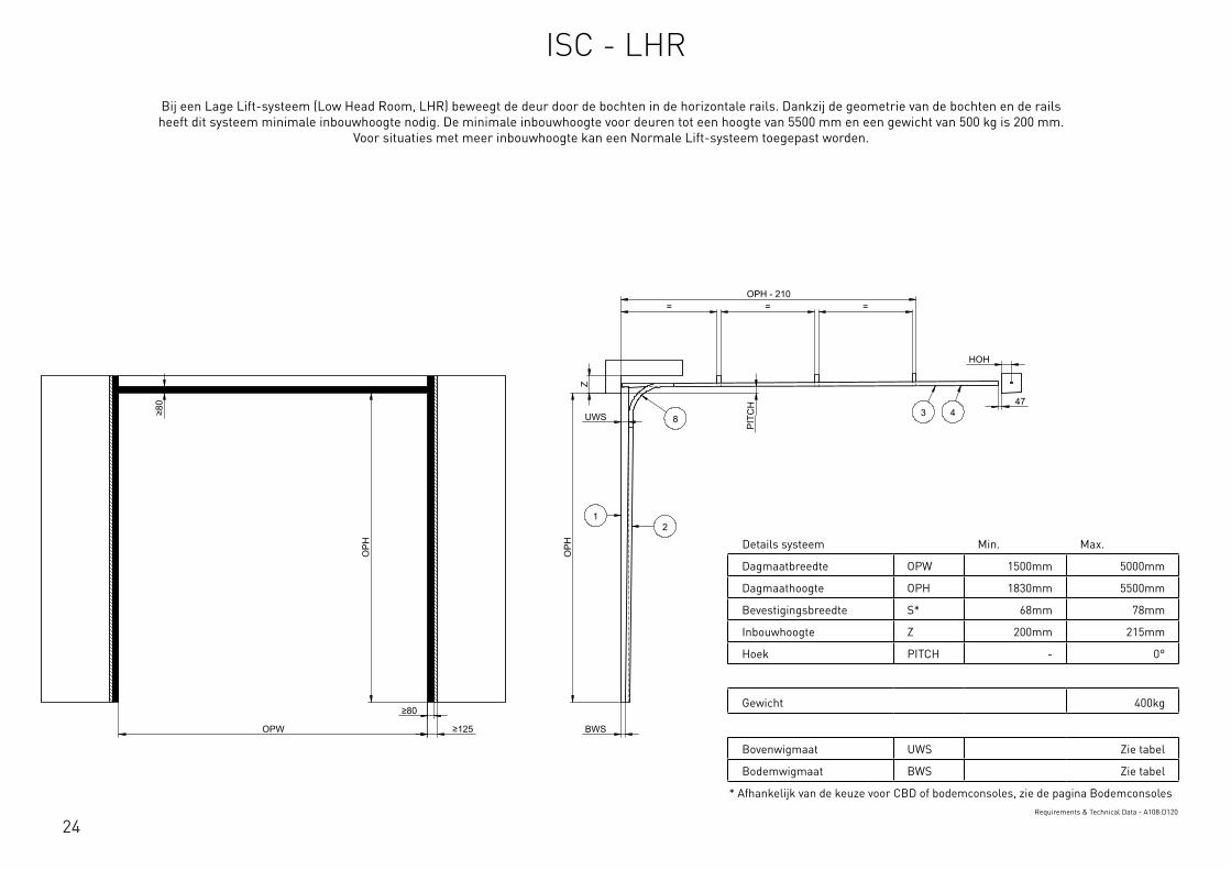
24
Details systeem Min. Max.
Dagmaatbreedte OPW 1500mm 5000mm
Dagmaathoogte OPH 1830mm 5500mm
Bevestigingsbreedte S* 68mm 78mm
Inbouwhoogte Z 200mm 215mm
Hoek PITCH - 0°
Gewicht 400kg
Bovenwigmaat UWS Zie tabel
Bodemwigmaat BWS Zie tabel
* Afhankelijk van de keuze voor CBD of bodemconsoles, zie de pagina BodemconsolesRequirements & Technical Data - A108:D120
OPH
UWS
BWS
PIT
CH
OPW
OPH
≥80
≥80
≥125
HOH
47
= = = OPH - 210
Z
12
3 48
This
wor
k is
cop
yrig
ht a
nd n
o pa
rt m
ay b
e re
prod
uced
, by
any
proc
ess,
nor
may
any
oth
er e
xclu
sive
righ
t be
exer
cise
d w
ithou
t the
per
mis
sion
of A
SSA
ABLO
Y.
Surface treatment:
V9_2
019_
02_2
1_dr
wRev.:Document ID
Material: General tolerance:
Volume: Mass: Surface area: Created (YYYY-MM-DD): Designed by: Drawn by: Scale: Projection:
Alternate ID142976550.27 mm³ 1:100 (A3)25577248.67 mm²142976.55 gram
ISO 8015ISO 2768-mH
1SHEET 1 OF 1Configuration:ISC-LHR
Bij een Lage Lift-systeem (Low Head Room, LHR) beweegt de deur door de bochten in de horizontale rails. Dankzij de geometrie van de bochten en de rails heeft dit systeem minimale inbouwhoogte nodig. De minimale inbouwhoogte voor deuren tot een hoogte van 5500 mm en een gewicht van 500 kg is 200 mm.
Voor situaties met meer inbouwhoogte kan een Normale Lift-systeem toegepast worden.
ISC - LHR
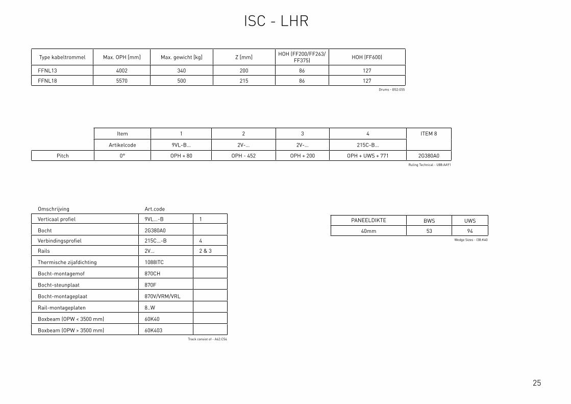
25
Type kabeltrommel Max. OPH [mm] Max. gewicht [kg] Z [mm] HOH (FF200/FF263/FF375) HOH (FF600)
FFNL13 4002 340 200 86 127
FFNL18 5570 500 215 86 127Drums - B52:G55
Item 1 2 3 4 ITEM 8
Artikelcode 9VL-B… 2V-… 2V-… 215C-B…
Pitch 0° OPH + 80 OPH - 452 OPH + 200 OPH + UWS + 771 2G380A0Ruling Technical - U88:AA91
PANEELDIKTE BWS UWS
40mm 53 94Wedge Sizes - I38:K40
Omschrijving Art.code
Verticaal profiel 9VL…-B 1
Bocht 2G380A0
Verbindingsprofiel 215C…-B 4
Rails 2V… 2 & 3
Thermische zijafdichting 1088ITC
Bocht-montagemof 870CH
Bocht-steunplaat 870F
Bocht-montageplaat 870V/VRM/VRL
Rail-montageplaten 8..W
Boxbeam (OPW < 3500 mm) 60K40
Boxbeam (OPW > 3500 mm) 60K403Track consist of - A42:C54
ISC - LHR

26
Details systeem Min. Max.
Dagmaatbreedte OPW 1500mm 5000mm
Dagmaathoogte OPH 1830mm 5500mm
Bevestigingsbreedte S* 68mm 78mm
Inbouwhoogte Z 200mm 215mm
Hoek PITCH 5° 35°
Gewicht 400kg
Bovenwigmaat UWS Zie tabel
Bodemwigmaat BWS Zie tabel
* Afhankelijk van de keuze voor CBD of bodemconsoles, zie de pagina BodemconsolesRequirements & Technical Data - G108:J120
OPH
UWS
BWS
PITCH
OPW
OPH
≥80
≥80
≥125
HOH
47
= = = OPH - 210
Z
12
34
8
This
wor
k is
cop
yrig
ht a
nd n
o pa
rt m
ay b
e re
prod
uced
, by
any
proc
ess,
nor
may
any
oth
er e
xclu
sive
righ
t be
exer
cise
d w
ithou
t the
per
mis
sion
of A
SSA
ABLO
Y.
Surface treatment:
V9_2
019_
02_2
1_dr
wRev.:Document ID
Material: General tolerance:
Volume: Mass: Surface area: Created (YYYY-MM-DD): Designed by: Drawn by: Scale: Projection:
Alternate ID142758386.18 mm³ 1:100 (A3)25601845.72 mm²142758.39 gram
ISO 8015ISO 2768-mH
1SHEET 1 OF 1Configuration:ISC-FHR
Bij een Lage Lift-systeem (Low Head Room, LHR) beweegt de deur door de bochten in de horizontale rails. Dankzij de geometrie van de bochten en de rails heeft dit systeem minimale inbouwhoogte nodig. De minimale inbouwhoogte voor deuren tot een hoogte van 5500 mm en een gewicht van 500 kg is 200 mm.
Voor situaties met meer inbouwhoogte kan een Normale Lift-systeem toegepast worden.
ISC - FLH
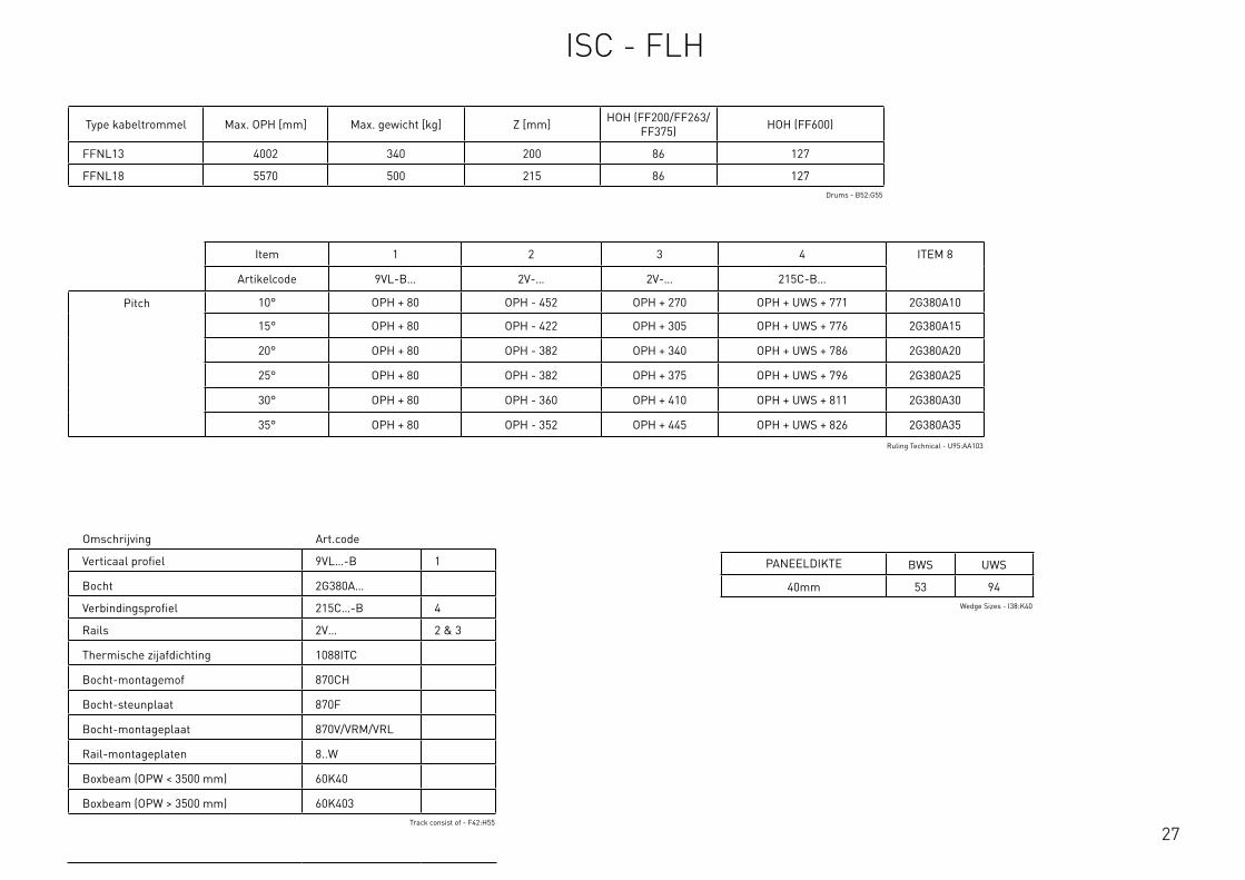
27
Type kabeltrommel Max. OPH [mm] Max. gewicht [kg] Z [mm] HOH (FF200/FF263/FF375) HOH (FF600)
FFNL13 4002 340 200 86 127
FFNL18 5570 500 215 86 127Drums - B52:G55
Item 1 2 3 4 ITEM 8
Artikelcode 9VL-B… 2V-… 2V-… 215C-B…
Pitch 10° OPH + 80 OPH - 452 OPH + 270 OPH + UWS + 771 2G380A10
15° OPH + 80 OPH - 422 OPH + 305 OPH + UWS + 776 2G380A15
20° OPH + 80 OPH - 382 OPH + 340 OPH + UWS + 786 2G380A20
25° OPH + 80 OPH - 382 OPH + 375 OPH + UWS + 796 2G380A25
30° OPH + 80 OPH - 360 OPH + 410 OPH + UWS + 811 2G380A30
35° OPH + 80 OPH - 352 OPH + 445 OPH + UWS + 826 2G380A35
Ruling Technical - U95:AA103
PANEELDIKTE BWS UWS
40mm 53 94Wedge Sizes - I38:K40
Omschrijving Art.code
Verticaal profiel 9VL…-B 1
Bocht 2G380A…
Verbindingsprofiel 215C…-B 4
Rails 2V… 2 & 3
Thermische zijafdichting 1088ITC
Bocht-montagemof 870CH
Bocht-steunplaat 870F
Bocht-montageplaat 870V/VRM/VRL
Rail-montageplaten 8..W
Boxbeam (OPW < 3500 mm) 60K40
Boxbeam (OPW > 3500 mm) 60K403Track consist of - F42:H55
ISC - FLH
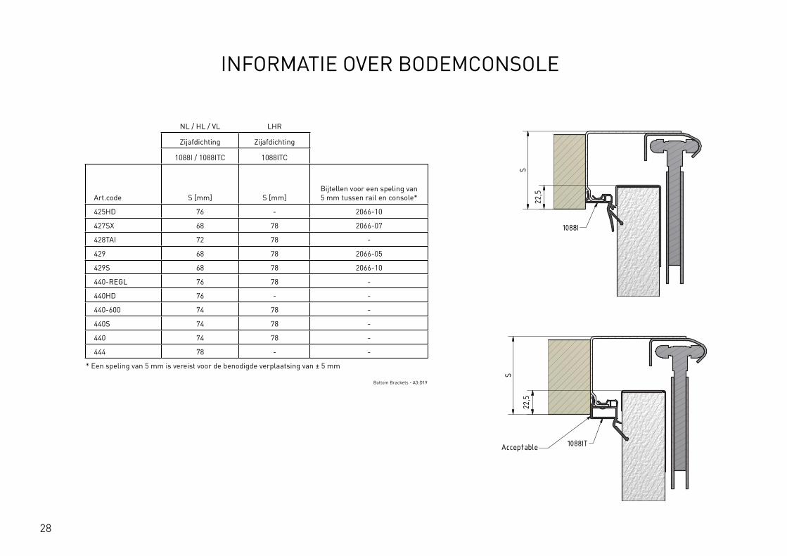
28
INFORMATIE OVER BODEMCONSOLE
NL / HL / VL LHR
Zijafdichting Zijafdichting
1088I / 1088ITC 1088ITC
Art.code S [mm] S [mm]Bijtellen voor een speling van 5 mm tussen rail en console*
425HD 76 - 2066-10
427SX 68 78 2066-07
428TAI 72 78 -
429 68 78 2066-05
429S 68 78 2066-10
440-REGL 76 78 -
440HD 76 - -
440-600 74 78 -
440S 74 78 -
440 74 78 -
444 78 - -
* Een speling van 5 mm is vereist voor de benodigde verplaatsing van ± 5 mm
Bottom Brackets - A3:D19
E E
F F
SCALE: GENERALROUGHNESS:
PROJECTION:FORMAT: UNIT:
mmTOLERANCES UNLESS
OTHERWISE STATED Acc. To ISO 2768-cK
MATERIAL
TREATMENT
DESCRIPTION
ARTICLE CODE DRAWING NUMBER REVISION
CREATION DATE NETTO WEIGHTCREATED BY
THICKNESS
FLAT WIDTH
FLAT LENGHT
mm
mm
mm
This drawing is property ofFlexiForce
and contains confidentionalinformation.
All rights are strictly reserved.Reproduction
and use for production purposesissue to
third parties in any form whatsoever,is not permitted without written authority from the proprietors.
36 001 001 A
Position of Vertical Angle based on Side Seal and Bottom Bracket
...
JiGa 9-8-2016 538,183 kg
-
A3-
-
---
-C:\V
aultWor
kspa
ce\R
&D\T
eke n
inge
n\36
\360
0100
1\36
001 0
01\4
40 -
108
8I.ia
m
0.5-3 >3-6 >6-30 >30-120 >120-400 >400-1000 >1000-2000 >2000-4000
:
:
:
: :
: : :
: : :
±0.20 ±0.30 ±0.50 ±0.80 ±1.20 ±2.00 ±3.00 ±4.00
Nomi
nal dime
nsion
:
3
A3 Changed values in table, see excel file JiGa 20-01-2017A2 Changed values in table, see excel file JiGa 10-01-2017REV. DESCRIPTION NAME DATE
Side Seal Side Seal 1088I / 1088IT
Bottom Bracket S [mm]Technical S [mm]CommercialAdd to achieve play of 5mm between track and bracket
425HD 75,5 76 2066-10427SX 67,5 68 2066-07428TAI 72 72 -429 67,5 68 2066-05429S 67,5 68 2066-10440-REGL 75,5 76 -440HD 75,5 76 -440-600 73,5 74 -440S 73,5 74 -440 73,5 74 -444 77,5 78 -
S
22,5
1088I
22,5
S
1088ITAcceptable
The play of 5mm is needed for the required pendel of +5mm/-5mm
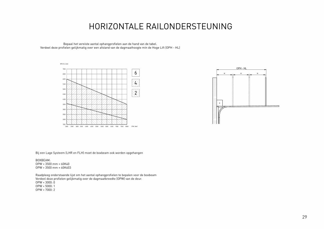
29
HORIZONTALE RAILONDERSTEUNING
Bepaal het vereiste aantal ophangprofielen aan de hand van de tabel. Verdeel deze profielen gelijkmatig over een afstand van de dagmaathoogte min de Hoge Lift (OPH - HL)
Bij een Lage Systeem (LHR en FLH) moet de boxbeam ook worden opgehangen BOXBEAM: OPW < 3500 mm = 60K40 OPW > 3500 mm = 60K403 Raadpleeg onderstaande lijst om het aantal ophangprofielen te bepalen voor de boxbeam Verdeel deze profielen gelijkmatig over de dagmaatbreedte (OPW) van de deur. OPW < 3000: 0 OPW < 5000: 1 OPW < 7000: 2
OPH
BWS
OPH
OPW
≥S
≥125
≥10
00
≥80
*
HL
+ Y
HL
+ Z
OPH - HL
= = = ≥250
12
This
wor
k is
cop
yrig
ht a
nd n
o pa
rt m
ay b
e re
prod
uced
, by
any
proc
ess,
nor
may
any
oth
er e
xclu
sive
righ
t be
exer
cise
d w
ithou
t the
per
mis
sion
of A
SSA
ABLO
Y.
Surface treatment:
V9_2
019_
02_2
1_dr
wRev.:Document ID
Material: General tolerance:
Volume: Mass: Surface area: Created (YYYY-MM-DD): Designed by: Drawn by: Scale: Projection:
Alternate ID415397163.98 mm³ 1:100 (A3)74737484.21 mm²415397.16 gram
ISO 8015ISO 2768-mH
1SHEET 1 OF 1Configuration:ISC-HL-1Piece

30
31
WAAR U ONS KUNT VINDEN
FlexiForce B.V. Hanzeweg 19 3771 NG Barneveld PO Box 37 3770 AA Barneveld Nederland +31-(0)342-427777 [email protected]
FlexiForce Hungary Kft. Medvefű str. 24 4031 Debrecen Hongarije +36-52561260 [email protected]
FlexiForce Ibérica, S.L. Apartado Correos 403 Ctra. Nacional 332, Km. 211 46780 – Oliva (Valencia) Spanje +34 96.285.82.50 [email protected]
FlexiForce Poland Sp. z o.o. Norblina 17/19 95-015 Głowno Polen +48 426500491 [email protected]
FlexiForce Italia Srl. Via dei Tigli CNM 25020 Alfianello Italië +39 0309936510 [email protected]
FlexiForce Turkey Marmara Geri Donusumculer Toplu İsyeri Yapı Kooperatifi Sekerpinar Mahallesi Aycicek Sokak Kapi No: 24 (245 ada, 31 parsel) 41420, Çayirova, KOCAELI / TURKIJE +90 262 658 2058 [email protected]
www.flexiforce.com
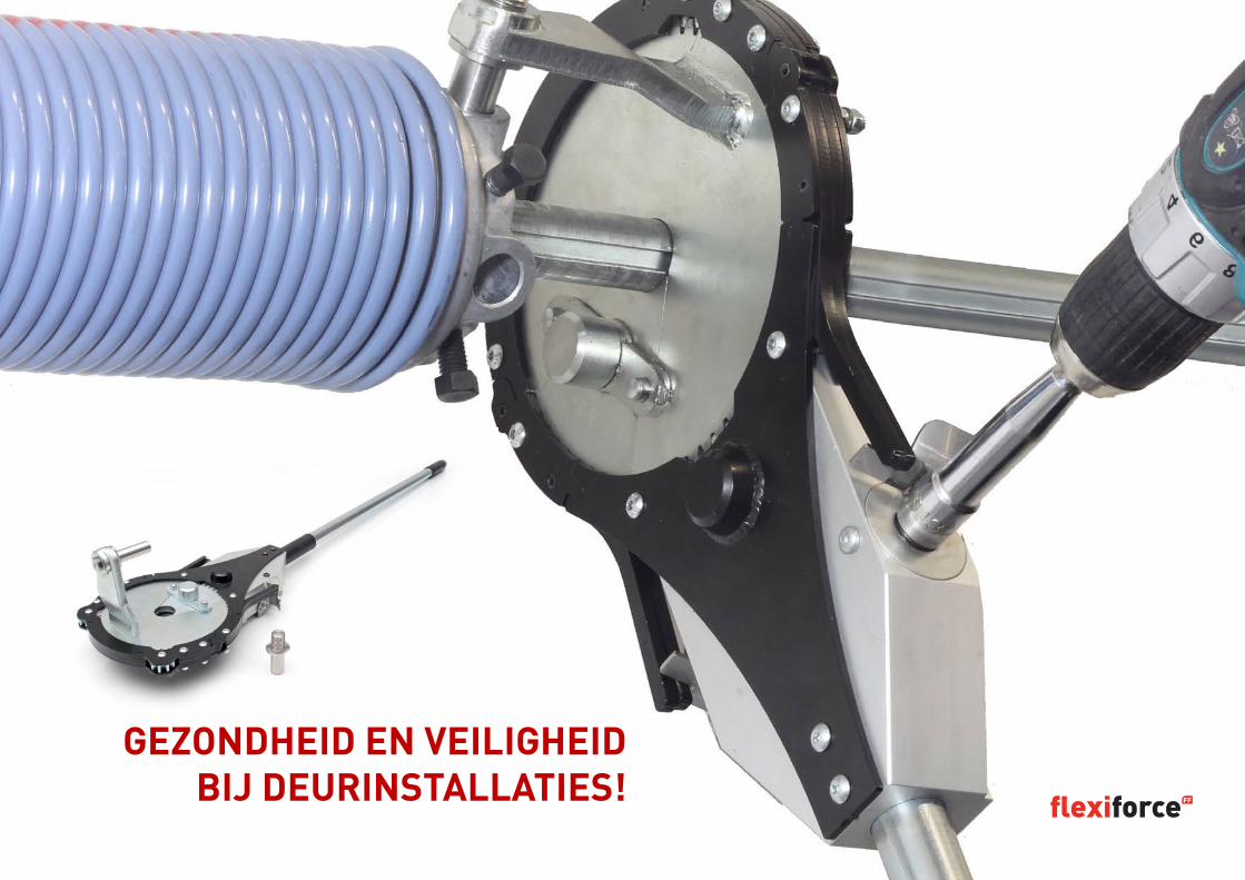
32
GEZONDHEID EN VEILIGHEID BIJ DEURINSTALLATIES!
1
NOTICE TECHNIQUEISC SYSTÈME QUINCAILLERIE INDUSTRIEL
FR. 3.1

2
INTRODUCTION
Cette notice technique est un outil d’assistance à la compréhension de toutes les fonctionnalités, dimensions et applications du FlexiForce ISC Système Quin-caillerie pour des portes industrielles. Pour des clients qui fabriquent leurs propres kits de quincaillerie, mais aussi pour des clients qui commandent des kits
tout prêts chez FlexiForce. Dans cette brochure vous trouverez une description de notre système, les différents systèmes de levage, les possibilités et pose en situations.
Des explications de base sur les portes sectionnelles industrielles et spécifications de construction ont été ajoutées. Pour les prix actuels et informations pour commander des kits nous vous prions de consulter la liste de prix ISC Système de Quincaillerie Industrielle. Si jamais il vous reste des questions, n’hésitez pas à contacter notre équipe de vente pour assistance ou trouvez plus d’information sur : www.flexifore.com
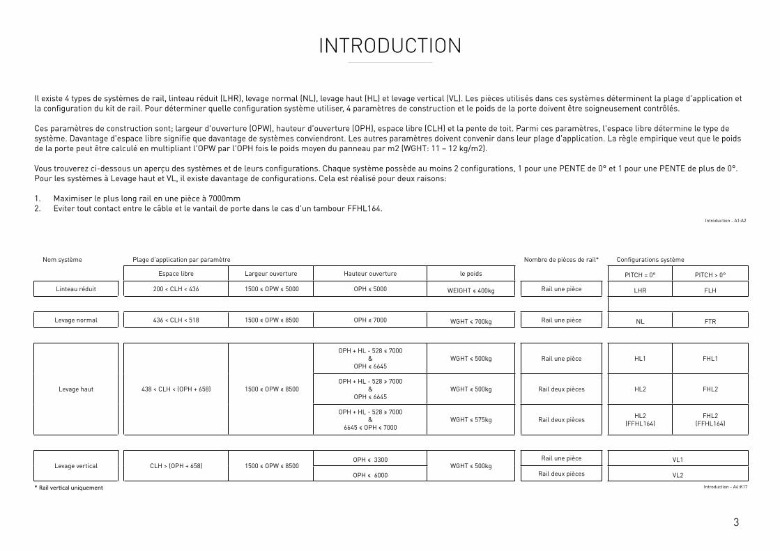
3
INTRODUCTION
Il existe 4 types de systèmes de rail, linteau réduit (LHR), levage normal (NL), levage haut (HL) et levage vertical (VL). Les pièces utilisés dans ces systèmes déterminent la plage d'application et la configuration du kit de rail. Pour déterminer quelle configuration système utiliser, 4 paramètres de construction et le poids de la porte doivent être soigneusement contrôlés. Ces paramètres de construction sont; largeur d'ouverture (OPW), hauteur d'ouverture (OPH), espace libre (CLH) et la pente de toit. Parmi ces paramètres, l'espace libre détermine le type de système. Davantage d'espace libre signifie que davantage de systèmes conviendront. Les autres paramètres doivent convenir dans leur plage d'application. La règle empirique veut que le poids de la porte peut être calculé en multipliant l'OPW par l'OPH fois le poids moyen du panneau par m2 (WGHT: 11 – 12 kg/m2). Vous trouverez ci-dessous un aperçu des systèmes et de leurs configurations. Chaque système possède au moins 2 configurations, 1 pour une PENTE de 0° et 1 pour une PENTE de plus de 0°. Pour les systèmes à Levage haut et VL, il existe davantage de configurations. Cela est réalisé pour deux raisons: 1. Maximiser le plus long rail en une pièce à 7000mm 2. Eviter tout contact entre le câble et le vantail de porte dans le cas d'un tambour FFHL164.
Introduction - A1:A2
Nom système Plage d’application par paramètre Nombre de pièces de rail* Configurations système
Espace libre Largeur ouverture Hauteur ouverture le poids PITCH = 0° PITCH > 0°
Linteau réduit 200 < CLH < 436 1500 ≤ OPW ≤ 5000 OPH ≤ 5000 WEIGHT ≤ 400kg Rail une pièce LHR FLH
Levage normal 436 < CLH < 518 1500 ≤ OPW ≤ 8500 OPH ≤ 7000 WGHT ≤ 700kg Rail une pièce NL FTR
Levage haut 438 < CLH < (OPH + 658) 1500 ≤ OPW ≤ 8500
OPH + HL - 528 ≤ 7000 &
OPH ≤ 6645WGHT ≤ 500kg Rail une pièce HL1 FHL1
OPH + HL - 528 ≥ 7000 &
OPH ≤ 6645WGHT ≤ 500kg Rail deux pièces HL2 FHL2
OPH + HL - 528 ≥ 7000 &
6645 ≤ OPH ≤ 7000WGHT ≤ 575kg Rail deux pièces HL2
(FFHL164)FHL2
(FFHL164)
Levage vertical CLH > (OPH + 658) 1500 ≤ OPW ≤ 8500OPH ≤ 3300
WGHT ≤ 500kgRail une pièce VL1
OPH ≤ 6000 Rail deux pièces VL2
* Rail vertical uniquement Introduction - A4:K17
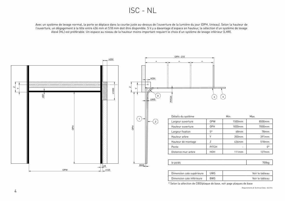
4
Détails du système Min. Max.
Largeur ouverture OPW 1500mm 8500mm
Hauteur ouverture OPH 1830mm 7000mm
Largeur fixation S* 68mm 78mm
Hauteur arbre Y 350mm 391mm
Hauteur de montage Z 436mm 518mm
Pente PITCH - 0°
Distance mur-arbre HOH 111mm 127mm
le poids 700kg
Dimension cale supérieure UWS Voir le tableau
Dimension cale inférieure BWS Voir le tableau
* Selon la sélection de CBD/plaque de base, voir page plaques de baseRequirements & Technical Data - A2:D16
OPH
UWS
HOH
Y
BWS
Z
PIT
CH
OPH
OPW
≥S
≥125
≥10
00
≥80
*
Y Z
OPH - 210
= = = ≥250
12
3 48
This
wor
k is
cop
yrig
ht a
nd n
o pa
rt m
ay b
e re
prod
uced
, by
any
proc
ess,
nor
may
any
oth
er e
xclu
sive
righ
t be
exer
cise
d w
ithou
t the
per
mis
sion
of A
SSA
ABLO
Y.
Surface treatment:
V9_2
019_
02_2
1_dr
wRev.:Document ID
Material: General tolerance:
Volume: Mass: Surface area: Created (YYYY-MM-DD): Designed by: Drawn by: Scale: Projection:
Alternate ID289465723.43 mm³ 1:100 (A3)54462775.75 mm²289465.72 gram
ISO 8015ISO 2768-mH
1SHEET 1 OF 1Configuration:ISC-NL
Avec un système de levage normal, la porte se déplace dans la courbe juste au-dessus de l’ouverture de la lumière du jour (OPH, linteau). Selon la hauteur de l’ouverture, un dégagement à la tête entre 436 mm et 518 mm doit être disponible. S’il y a davantage d’espace en hauteur, la sélection d’un système de levage
élevé (HL) est préférable. Un espace au niveau de la hauteur moins important requiert le choix d’un système de levage inférieur (LHR).
ISC - NL
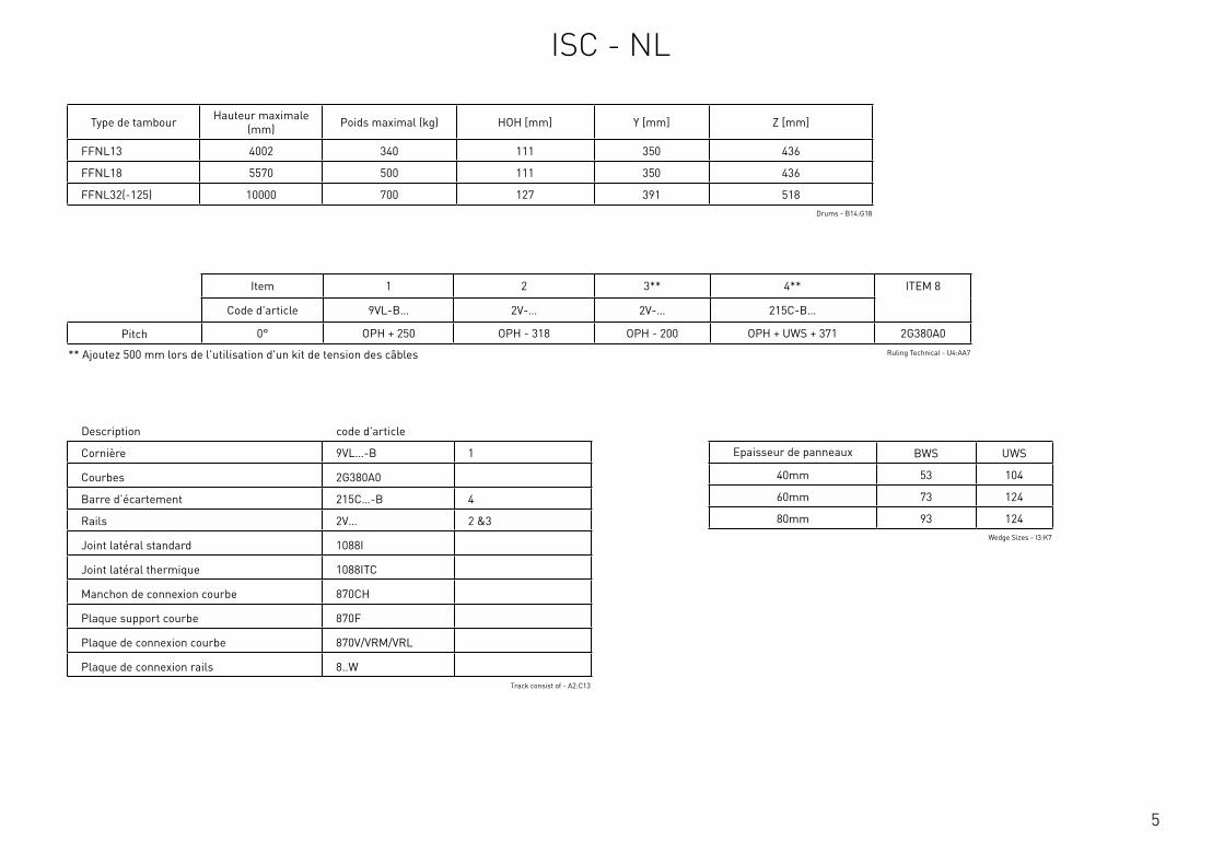
5
Détails du système Min. Max.
Largeur ouverture OPW 1500mm 8500mm
Hauteur ouverture OPH 1830mm 7000mm
Largeur fixation S* 68mm 78mm
Hauteur arbre Y 350mm 391mm
Hauteur de montage Z 436mm 518mm
Pente PITCH - 0°
Distance mur-arbre HOH 111mm 127mm
le poids 700kg
Dimension cale supérieure UWS Voir le tableau
Dimension cale inférieure BWS Voir le tableau
* Selon la sélection de CBD/plaque de base, voir page plaques de baseRequirements & Technical Data - A2:D16
Description code d'article
Cornière 9VL…-B 1
Courbes 2G380A0
Barre d’écartement 215C…-B 4
Rails 2V… 2 &3
Joint latéral standard 1088I
Joint latéral thermique 1088ITC
Manchon de connexion courbe 870CH
Plaque support courbe 870F
Plaque de connexion courbe 870V/VRM/VRL
Plaque de connexion rails 8..WTrack consist of - A2:C13
Type de tambour Hauteur maximale (mm) Poids maximal (kg) HOH [mm] Y [mm] Z [mm]
FFNL13 4002 340 111 350 436
FFNL18 5570 500 111 350 436
FFNL32(-125) 10000 700 127 391 518Drums - B14:G18
Item 1 2 3** 4** ITEM 8
Code d'article 9VL-B… 2V-… 2V-… 215C-B…
Pitch 0° OPH + 250 OPH - 318 OPH - 200 OPH + UWS + 371 2G380A0
** Ajoutez 500 mm lors de l'utilisation d'un kit de tension des câbles Ruling Technical - U4:AA7
Epaisseur de panneaux BWS UWS
40mm 53 104
60mm 73 124
80mm 93 124Wedge Sizes - I3:K7
ISC - NL
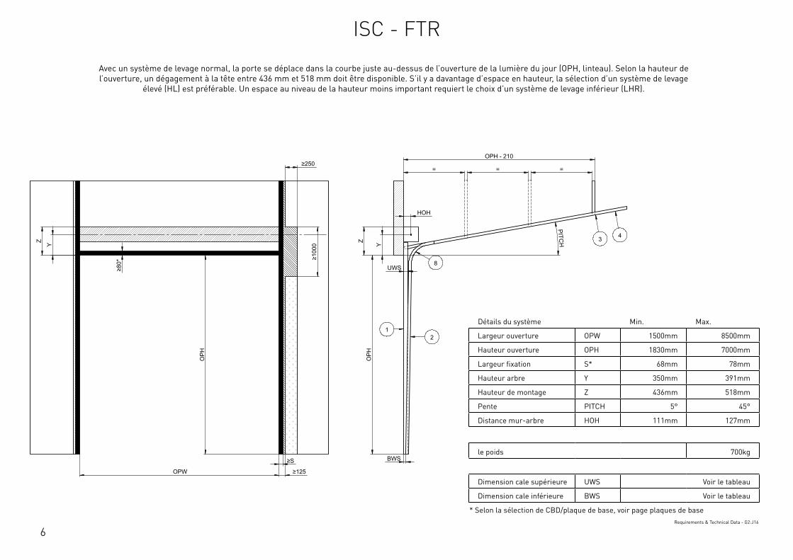
6
Détails du système Min. Max.
Largeur ouverture OPW 1500mm 8500mm
Hauteur ouverture OPH 1830mm 7000mm
Largeur fixation S* 68mm 78mm
Hauteur arbre Y 350mm 391mm
Hauteur de montage Z 436mm 518mm
Pente PITCH 5° 45°
Distance mur-arbre HOH 111mm 127mm
le poids 700kg
Dimension cale supérieure UWS Voir le tableau
Dimension cale inférieure BWS Voir le tableau
* Selon la sélection de CBD/plaque de base, voir page plaques de baseRequirements & Technical Data - G2:J16
OPH
UWS
HOH
Y
BWS
Z
PITCH
OPH
OPW
≥S
≥125
≥10
00
≥80
*
Y Z
OPH - 210
= = = ≥250
12
3 4
8
This
wor
k is
cop
yrig
ht a
nd n
o pa
rt m
ay b
e re
prod
uced
, by
any
proc
ess,
nor
may
any
oth
er e
xclu
sive
righ
t be
exer
cise
d w
ithou
t the
per
mis
sion
of A
SSA
ABLO
Y.
Surface treatment:
V9_2
019_
02_2
1_dr
wRev.:Document ID
Material: General tolerance:
Volume: Mass: Surface area: Created (YYYY-MM-DD): Designed by: Drawn by: Scale: Projection:
Alternate ID289310826.07 mm³ 1:100 (A3)54414606.92 mm²289310.83 gram
ISO 8015ISO 2768-mH
1SHEET 1 OF 1Configuration:ISC-FTR
Avec un système de levage normal, la porte se déplace dans la courbe juste au-dessus de l’ouverture de la lumière du jour (OPH, linteau). Selon la hauteur de l’ouverture, un dégagement à la tête entre 436 mm et 518 mm doit être disponible. S’il y a davantage d’espace en hauteur, la sélection d’un système de levage
élevé (HL) est préférable. Un espace au niveau de la hauteur moins important requiert le choix d’un système de levage inférieur (LHR).
ISC - FTR
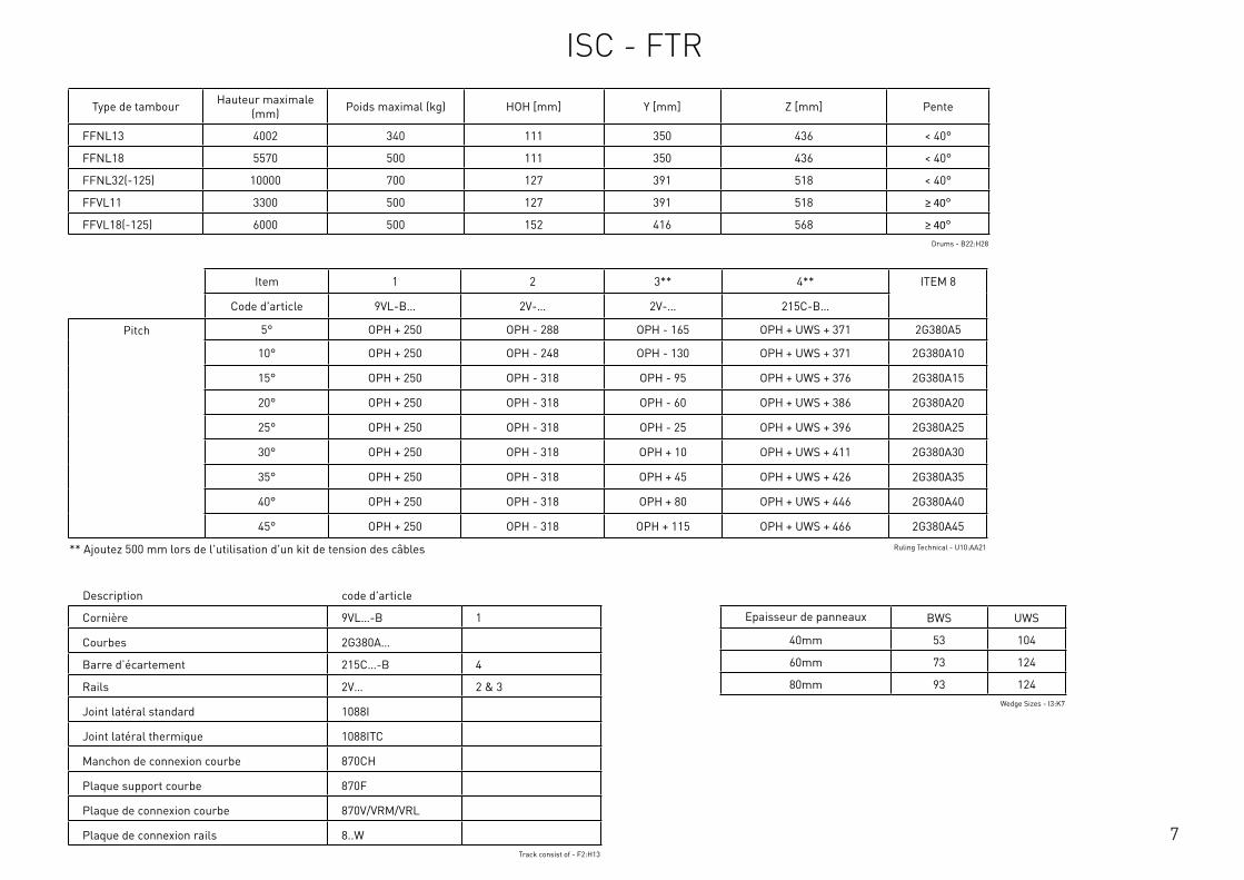
7
Description code d'article
Cornière 9VL…-B 1
Courbes 2G380A…
Barre d’écartement 215C…-B 4
Rails 2V… 2 & 3
Joint latéral standard 1088I
Joint latéral thermique 1088ITC
Manchon de connexion courbe 870CH
Plaque support courbe 870F
Plaque de connexion courbe 870V/VRM/VRL
Plaque de connexion rails 8..WTrack consist of - F2:H13
Type de tambour Hauteur maximale (mm) Poids maximal (kg) HOH [mm] Y [mm] Z [mm] Pente
FFNL13 4002 340 111 350 436 < 40°
FFNL18 5570 500 111 350 436 < 40°
FFNL32(-125) 10000 700 127 391 518 < 40°
FFVL11 3300 500 127 391 518 ≥ 40°
FFVL18(-125) 6000 500 152 416 568 ≥ 40°Drums - B22:H28
Item 1 2 3** 4** ITEM 8
Code d'article 9VL-B… 2V-… 2V-… 215C-B…
Pitch 5° OPH + 250 OPH - 288 OPH - 165 OPH + UWS + 371 2G380A5
10° OPH + 250 OPH - 248 OPH - 130 OPH + UWS + 371 2G380A10
15° OPH + 250 OPH - 318 OPH - 95 OPH + UWS + 376 2G380A15
20° OPH + 250 OPH - 318 OPH - 60 OPH + UWS + 386 2G380A20
25° OPH + 250 OPH - 318 OPH - 25 OPH + UWS + 396 2G380A25
30° OPH + 250 OPH - 318 OPH + 10 OPH + UWS + 411 2G380A30
35° OPH + 250 OPH - 318 OPH + 45 OPH + UWS + 426 2G380A35
40° OPH + 250 OPH - 318 OPH + 80 OPH + UWS + 446 2G380A40
45° OPH + 250 OPH - 318 OPH + 115 OPH + UWS + 466 2G380A45
** Ajoutez 500 mm lors de l'utilisation d'un kit de tension des câbles Ruling Technical - U10:AA21
Epaisseur de panneaux BWS UWS
40mm 53 104
60mm 73 124
80mm 93 124Wedge Sizes - I3:K7
ISC - FTR
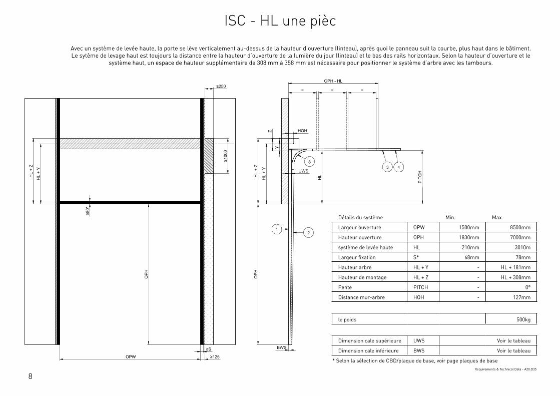
8
Détails du système Min. Max.
Largeur ouverture OPW 1500mm 8500mm
Hauteur ouverture OPH 1830mm 7000mm
système de levée haute HL 210mm 3010m
Largeur fixation S* 68mm 78mm
Hauteur arbre HL + Y - HL + 181mm
Hauteur de montage HL + Z - HL + 308mm
Pente PITCH - 0°
Distance mur-arbre HOH - 127mm
le poids 500kg
Dimension cale supérieure UWS Voir le tableau
Dimension cale inférieure BWS Voir le tableau
* Selon la sélection de CBD/plaque de base, voir page plaques de baseRequirements & Technical Data - A20:D35
OPH
UWS
HOH
BWS
PIT
CH
OPH
OPW
≥S
≥125
≥10
00
≥80
*
HL
+ Y
HL
+ Z
OPH - HL
= = =
HL
Y
Z
≥250
HL
+ Y
HL
+ Z
12
3 48
This
wor
k is
cop
yrig
ht a
nd n
o pa
rt m
ay b
e re
prod
uced
, by
any
proc
ess,
nor
may
any
oth
er e
xclu
sive
righ
t be
exer
cise
d w
ithou
t the
per
mis
sion
of A
SSA
ABLO
Y.
Surface treatment:
V9_2
019_
02_2
1_dr
wRev.:Document ID
Material: General tolerance:
Volume: Mass: Surface area: Created (YYYY-MM-DD): Designed by: Drawn by: Scale: Projection:
Alternate ID415397163.98 mm³ 1:100 (A3)74737484.21 mm²415397.16 gram
ISO 8015ISO 2768-mH
1SHEET 1 OF 1Configuration:ISC-HL-1Piece
Avec un système de levée haute, la porte se lève verticalement au-dessus de la hauteur d’ouverture (linteau), après quoi le panneau suit la courbe, plus haut dans le bâtiment. Le sytème de levage haut est toujours la distance entre la hauteur d’ouverture de la lumière du jour (linteau) et le bas des rails horizontaux. Selon la hauteur d’ouverture et le
système haut, un espace de hauteur supplémentaire de 308 mm à 358 mm est nécessaire pour positionner le système d’arbre avec les tambours.
ISC - HL une pièc
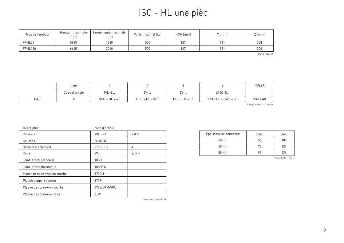
9
Description code d'article
Cornière 9VL…-B 1 & 5
Courbes 2G380A0
Barre d’écartement 215C…-B 4
Rails 2V… 2, 3, 6
Joint latéral standard 1088I
Joint latéral thermique 1088ITC
Manchon de connexion courbe 870CH
Plaque support courbe 870F
Plaque de connexion courbe 870V/VRM/VRL
Plaque de connexion rails 8..WTrack consist of - A17:C28
Type de tambour Hauteur maximale (mm)
Levée haute maximale (mm) Poids maximal (kg) HOH [mm] Y [mm] Z [mm]
FFHL54 5945 1380 500 127 181 308
FFHL120 6645 3010 500 127 181 308Drums - B32:H35
Item 1 2 3 4 ITEM 8
Code d'article 9VL-B… 2V-… 2V-… 215C-B…
Pitch 0 OPH + HL + 40 OPH + HL - 528 OPH - HL + 10 OPH - HL + UWS + 581 2G380A0Ruling Technical - U25:AA28
Epaisseur de panneaux BWS UWS
40mm 53 104
60mm 73 124
80mm 93 124Wedge Sizes - I10:K14
ISC - HL une pièc
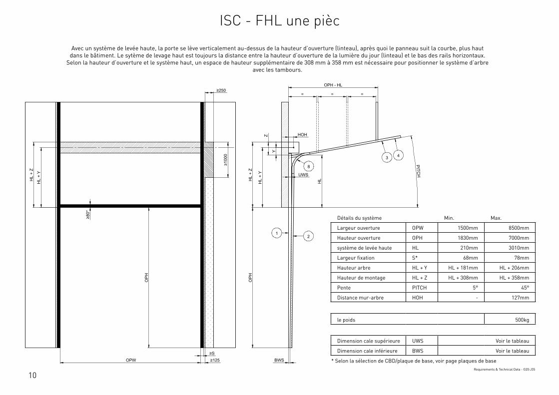
10
Détails du système Min. Max.
Largeur ouverture OPW 1500mm 8500mm
Hauteur ouverture OPH 1830mm 7000mm
système de levée haute HL 210mm 3010mm
Largeur fixation S* 68mm 78mm
Hauteur arbre HL + Y HL + 181mm HL + 206mm
Hauteur de montage HL + Z HL + 308mm HL + 358mm
Pente PITCH 5° 45°
Distance mur-arbre HOH - 127mm
le poids 500kg
Dimension cale supérieure UWS Voir le tableau
Dimension cale inférieure BWS Voir le tableau
* Selon la sélection de CBD/plaque de base, voir page plaques de baseRequirements & Technical Data - G20:J35
OPH
UWS
HOH
HL
+ Y
BWS
HL
+ Z
PITCH
O
PH
OPW ≥S ≥125
≥10
00
≥80
*
HL
+ Y
HL
+ Z
OPH - HL
= = =
HL
Z
Y
≥250
12
3 4
8
This
wor
k is
cop
yrig
ht a
nd n
o pa
rt m
ay b
e re
prod
uced
, by
any
proc
ess,
nor
may
any
oth
er e
xclu
sive
righ
t be
exer
cise
d w
ithou
t the
per
mis
sion
of A
SSA
ABLO
Y.
Surface treatment:
V9_2
019_
02_2
1_dr
wRev.:Document ID
Material: General tolerance:
Volume: Mass: Surface area: Created (YYYY-MM-DD): Designed by: Drawn by: Scale: Projection:
Alternate ID415364243.14 mm³ 1:100 (A3)74721651.39 mm²415364.24 gram
ISO 8015ISO 2768-mH
1SHEET 1 OF 1Configuration:ISC-FHL-1Piece
Avec un système de levée haute, la porte se lève verticalement au-dessus de la hauteur d’ouverture (linteau), après quoi le panneau suit la courbe, plus haut dans le bâtiment. Le sytème de levage haut est toujours la distance entre la hauteur d’ouverture de la lumière du jour (linteau) et le bas des rails horizontaux.
Selon la hauteur d’ouverture et le système haut, un espace de hauteur supplémentaire de 308 mm à 358 mm est nécessaire pour positionner le système d’arbre avec les tambours.
ISC - FHL une pièc
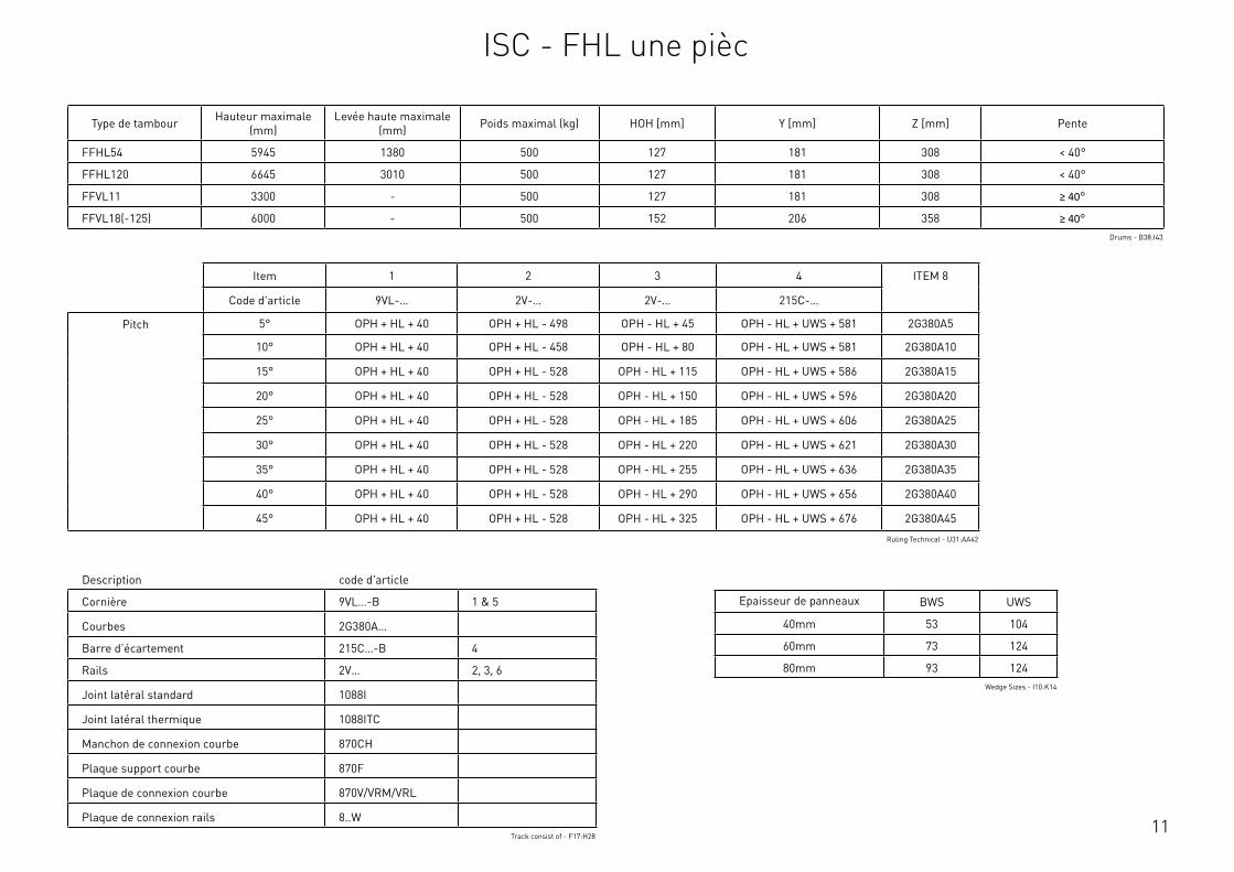
11
Description code d'article
Cornière 9VL…-B 1 & 5
Courbes 2G380A…
Barre d’écartement 215C…-B 4
Rails 2V… 2, 3, 6
Joint latéral standard 1088I
Joint latéral thermique 1088ITC
Manchon de connexion courbe 870CH
Plaque support courbe 870F
Plaque de connexion courbe 870V/VRM/VRL
Plaque de connexion rails 8..WTrack consist of - F17:H28
Type de tambour Hauteur maximale (mm)
Levée haute maximale (mm) Poids maximal (kg) HOH [mm] Y [mm] Z [mm] Pente
FFHL54 5945 1380 500 127 181 308 < 40°
FFHL120 6645 3010 500 127 181 308 < 40°
FFVL11 3300 - 500 127 181 308 ≥ 40°
FFVL18(-125) 6000 - 500 152 206 358 ≥ 40°Drums - B38:I43
Item 1 2 3 4 ITEM 8
Code d'article 9VL-… 2V-… 2V-… 215C-…
Pitch 5° OPH + HL + 40 OPH + HL - 498 OPH - HL + 45 OPH - HL + UWS + 581 2G380A5
10° OPH + HL + 40 OPH + HL - 458 OPH - HL + 80 OPH - HL + UWS + 581 2G380A10
15° OPH + HL + 40 OPH + HL - 528 OPH - HL + 115 OPH - HL + UWS + 586 2G380A15
20° OPH + HL + 40 OPH + HL - 528 OPH - HL + 150 OPH - HL + UWS + 596 2G380A20
25° OPH + HL + 40 OPH + HL - 528 OPH - HL + 185 OPH - HL + UWS + 606 2G380A25
30° OPH + HL + 40 OPH + HL - 528 OPH - HL + 220 OPH - HL + UWS + 621 2G380A30
35° OPH + HL + 40 OPH + HL - 528 OPH - HL + 255 OPH - HL + UWS + 636 2G380A35
40° OPH + HL + 40 OPH + HL - 528 OPH - HL + 290 OPH - HL + UWS + 656 2G380A40
45° OPH + HL + 40 OPH + HL - 528 OPH - HL + 325 OPH - HL + UWS + 676 2G380A45
Ruling Technical - U31:AA42
Epaisseur de panneaux BWS UWS
40mm 53 104
60mm 73 124
80mm 93 124Wedge Sizes - I10:K14
ISC - FHL une pièc
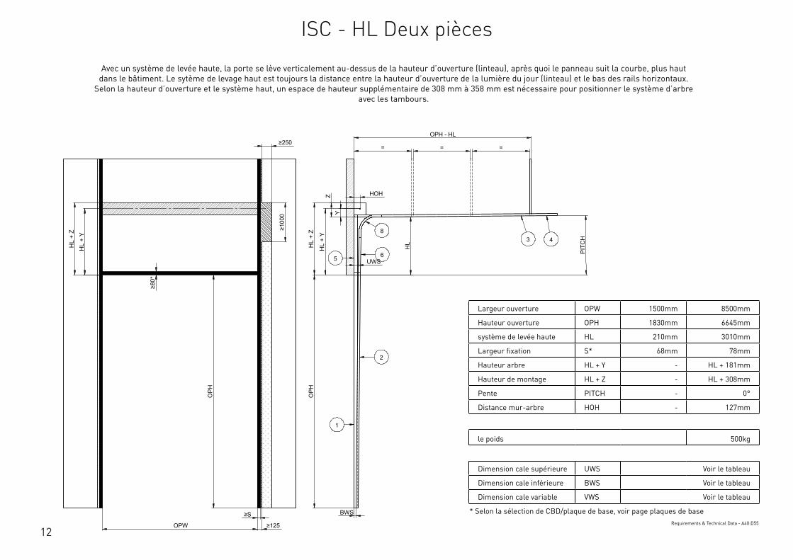
12
Largeur ouverture OPW 1500mm 8500mm
Hauteur ouverture OPH 1830mm 6645mm
système de levée haute HL 210mm 3010mm
Largeur fixation S* 68mm 78mm
Hauteur arbre HL + Y - HL + 181mm
Hauteur de montage HL + Z - HL + 308mm
Pente PITCH - 0°
Distance mur-arbre HOH - 127mm
le poids 500kg
Dimension cale supérieure UWS Voir le tableau
Dimension cale inférieure BWS Voir le tableau
Dimension cale variable VWS Voir le tableau
* Selon la sélection de CBD/plaque de base, voir page plaques de baseRequirements & Technical Data - A40:D55
OPH
UWS
HOH
HL
+ Y
BWS
HL
+ Z
PIT
CH
OPH
OPW
≥S
≥125
≥10
00
≥80
*
HL
+ Y
HL
+ Z
OPH - HL
= = =
HL
Y
Z
≥250
2
3 48
1
65
This
wor
k is
cop
yrig
ht a
nd n
o pa
rt m
ay b
e re
prod
uced
, by
any
proc
ess,
nor
may
any
oth
er e
xclu
sive
righ
t be
exer
cise
d w
ithou
t the
per
mis
sion
of A
SSA
ABLO
Y.
Surface treatment:
V9_2
019_
02_2
1_dr
wRev.:Document ID
Material: General tolerance:
Volume: Mass: Surface area: Created (YYYY-MM-DD): Designed by: Drawn by: Scale: Projection:
Alternate ID488235193.04 mm³ 1:100 (A3)89835498.33 mm²488235.19 gram
ISO 8015ISO 2768-mH
1SHEET 1 OF 1Configuration:ISC-HL-2Piece
Avec un système de levée haute, la porte se lève verticalement au-dessus de la hauteur d’ouverture (linteau), après quoi le panneau suit la courbe, plus haut dans le bâtiment. Le sytème de levage haut est toujours la distance entre la hauteur d’ouverture de la lumière du jour (linteau) et le bas des rails horizontaux.
Selon la hauteur d’ouverture et le système haut, un espace de hauteur supplémentaire de 308 mm à 358 mm est nécessaire pour positionner le système d’arbre avec les tambours.
ISC - HL Deux pièces
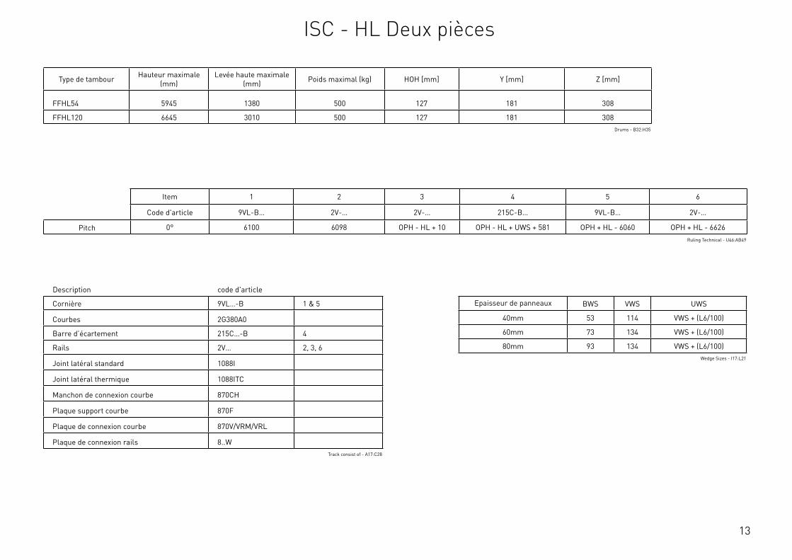
13
Description code d'article
Cornière 9VL…-B 1 & 5
Courbes 2G380A0
Barre d’écartement 215C…-B 4
Rails 2V… 2, 3, 6
Joint latéral standard 1088I
Joint latéral thermique 1088ITC
Manchon de connexion courbe 870CH
Plaque support courbe 870F
Plaque de connexion courbe 870V/VRM/VRL
Plaque de connexion rails 8..WTrack consist of - A17:C28
Type de tambour Hauteur maximale (mm)
Levée haute maximale (mm) Poids maximal (kg) HOH [mm] Y [mm] Z [mm]
FFHL54 5945 1380 500 127 181 308
FFHL120 6645 3010 500 127 181 308Drums - B32:H35
Item 1 2 3 4 5 6
Code d'article 9VL-B… 2V-… 2V-… 215C-B… 9VL-B… 2V-…
Pitch 0° 6100 6098 OPH - HL + 10 OPH - HL + UWS + 581 OPH + HL - 6060 OPH + HL - 6626Ruling Technical - U46:AB49
Epaisseur de panneaux BWS VWS UWS
40mm 53 114 VWS + (L6/100)
60mm 73 134 VWS + (L6/100)
80mm 93 134 VWS + (L6/100)Wedge Sizes - I17:L21
ISC - HL Deux pièces
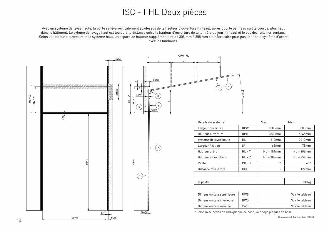
14
Détails du système Min. Max.
Largeur ouverture OPW 1500mm 8500mm
Hauteur ouverture OPH 1830mm 6645mm
système de levée haute HL 210mm 3010mm
Largeur fixation S* 68mm 78mm
Hauteur arbre HL + Y HL + 181mm HL + 206mm
Hauteur de montage HL + Z HL + 308mm HL + 358mm
Pente PITCH 5° 45°
Distance mur-arbre HOH - 127mm
le poids 500kg
Dimension cale supérieure UWS Voir le tableau
Dimension cale inférieure BWS Voir le tableau
Dimension cale variable VWS Voir le tableau
* Selon la sélection de CBD/plaque de base, voir page plaques de baseRequirements & Technical Data - G39:J55
OPH
UWS
HOH
HL
+ Y
BWS
HL
+ Z
PITCH
O
PH
OPW
≥S
≥125
≥10
00
≥80
*
HL
+ Y
HL
+ Z
OPH - HL
= = =
HL
VWS
Z
Y
≥250
2
34
8
1
65
This
wor
k is
cop
yrig
ht a
nd n
o pa
rt m
ay b
e re
prod
uced
, by
any
proc
ess,
nor
may
any
oth
er e
xclu
sive
righ
t be
exer
cise
d w
ithou
t the
per
mis
sion
of A
SSA
ABLO
Y.
Surface treatment:
V9_2
019_
02_2
1_dr
wRev.:Document ID
Material: General tolerance:
Volume: Mass: Surface area: Created (YYYY-MM-DD): Designed by: Drawn by: Scale: Projection:
Alternate ID488036705.35 mm³ 1:100 (A3)89774518.55 mm²488036.71 gram
ISO 8015ISO 2768-mH
1SHEET 1 OF 1Configuration:ISC-FHL-2Piece
Avec un système de levée haute, la porte se lève verticalement au-dessus de la hauteur d’ouverture (linteau), après quoi le panneau suit la courbe, plus haut dans le bâtiment. Le sytème de levage haut est toujours la distance entre la hauteur d’ouverture de la lumière du jour (linteau) et le bas des rails horizontaux.
Selon la hauteur d’ouverture et le système haut, un espace de hauteur supplémentaire de 308 mm à 358 mm est nécessaire pour positionner le système d’arbre avec les tambours.
ISC - FHL Deux pièces

15
Description code d'article
Cornière 9VL…-B 1 & 5
Courbes 2G380A…
Barre d’écartement 215C…-B 4
Rails 2V… 2, 3, 6
Joint latéral standard 1088I
Joint latéral thermique 1088ITC
Manchon de connexion courbe 870CH
Plaque support courbe 870F
Plaque de connexion courbe 870V/VRM/VRL
Plaque de connexion rails 8..WTrack consist of - F17:H28
Type de tambour Hauteur maximale (mm)
Levée haute maximale (mm) Poids maximal (kg) HOH [mm] Y [mm] Z [mm] Pente
FFHL54 5945 1380 500 127 181 308 < 40°
FFHL120 6645 3010 500 127 181 308 < 40°
FFVL11 3300 - 500 127 181 308 ≥ 40°
FFVL18(-125) 6000 - 500 152 206 358 ≥ 40°Drums - B38:I43
Item 1 2 3 4 5 6
Code d'article 9VL-B… 2V-… 2V-… 215C-B… 9VL-B… 2V-…
Pitch 5° 6100 6098 OPH - HL + 45 OPH - HL + UWS + 581 OPH + HL - 6060 OPH + HL - 6656
10° 6100 6098 OPH - HL + 80 OPH - HL + UWS + 581 OPH + HL - 6060 OPH + HL - 6696
15° 6100 6098 OPH - HL + 115 OPH - HL + UWS + 586 OPH + HL - 6060 OPH + HL - 6626
20° 6100 6098 OPH - HL + 150 OPH - HL + UWS + 596 OPH + HL - 6060 OPH + HL - 6626
25° 6100 6098 OPH - HL + 185 OPH - HL + UWS + 606 OPH + HL - 6060 OPH + HL - 6626
30° 6100 6098 OPH - HL + 220 OPH - HL + UWS + 621 OPH + HL - 6060 OPH + HL - 6626
35° 6100 6098 OPH - HL + 255 OPH - HL + UWS + 636 OPH + HL - 6060 OPH + HL - 6626
40° 6100 6098 OPH - HL + 290 OPH - HL + UWS + 656 OPH + HL - 6060 OPH + HL - 6626
45° 6100 6098 OPH - HL + 325 OPH - HL + UWS + 676 OPH + HL - 6060 OPH + HL - 6626
Ruling Technical - U52:AB63
Epaisseur de panneaux BWS VWS UWS
40mm 53 114 VWS + (L6/100)
60mm 73 134 VWS + (L6/100)
80mm 93 134 VWS + (L6/100)Wedge Sizes - I17:L21
ISC - FHL Deux pièces
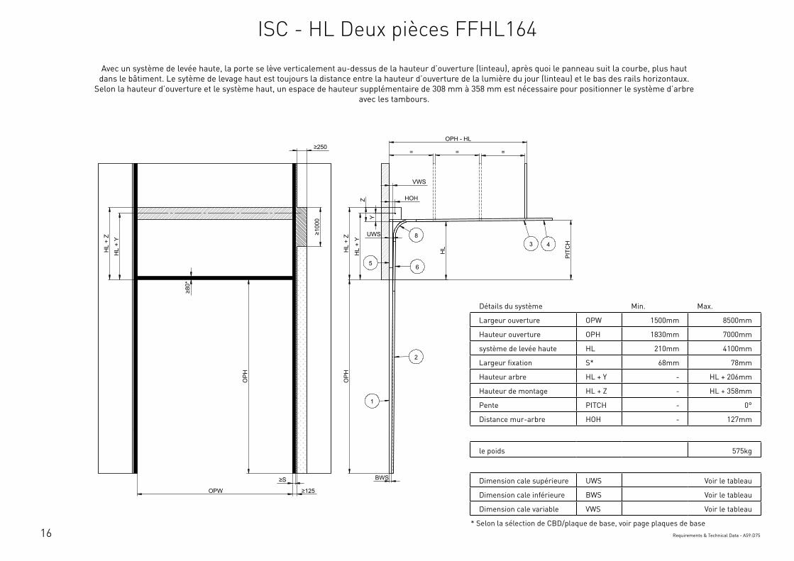
16
Détails du système Min. Max.
Largeur ouverture OPW 1500mm 8500mm
Hauteur ouverture OPH 1830mm 7000mm
système de levée haute HL 210mm 4100mm
Largeur fixation S* 68mm 78mm
Hauteur arbre HL + Y - HL + 206mm
Hauteur de montage HL + Z - HL + 358mm
Pente PITCH - 0°
Distance mur-arbre HOH - 127mm
le poids 575kg
Dimension cale supérieure UWS Voir le tableau
Dimension cale inférieure BWS Voir le tableau
Dimension cale variable VWS Voir le tableau
* Selon la sélection de CBD/plaque de base, voir page plaques de baseRequirements & Technical Data - A59:D75
OPH
UWS
HOH
HL
+ Y
BWS
HL
+ Z
PIT
CH
OPH
OPW
≥S
≥125
≥10
00
≥80
*
HL
+ Y
HL
+ Z
OPH - HL
= = =
HL
VWS
Y
Z
≥250
2
3 48
1
65
This
wor
k is
cop
yrig
ht a
nd n
o pa
rt m
ay b
e re
prod
uced
, by
any
proc
ess,
nor
may
any
oth
er e
xclu
sive
righ
t be
exer
cise
d w
ithou
t the
per
mis
sion
of A
SSA
ABLO
Y.
Surface treatment:
V9_2
019_
02_2
1_dr
wRev.:Document ID
Material: General tolerance:
Volume: Mass: Surface area: Created (YYYY-MM-DD): Designed by: Drawn by: Scale: Projection:
Alternate ID450571832.56 mm³ 1:100 (A3)82034869.87 mm²450571.83 gram
ISO 8015ISO 2768-mH
1SHEET 1 OF 1Configuration:ISC-HL-FFHL164-2Piece
Avec un système de levée haute, la porte se lève verticalement au-dessus de la hauteur d’ouverture (linteau), après quoi le panneau suit la courbe, plus haut dans le bâtiment. Le sytème de levage haut est toujours la distance entre la hauteur d’ouverture de la lumière du jour (linteau) et le bas des rails horizontaux.
Selon la hauteur d’ouverture et le système haut, un espace de hauteur supplémentaire de 308 mm à 358 mm est nécessaire pour positionner le système d’arbre avec les tambours.
ISC - HL Deux pièces FFHL164
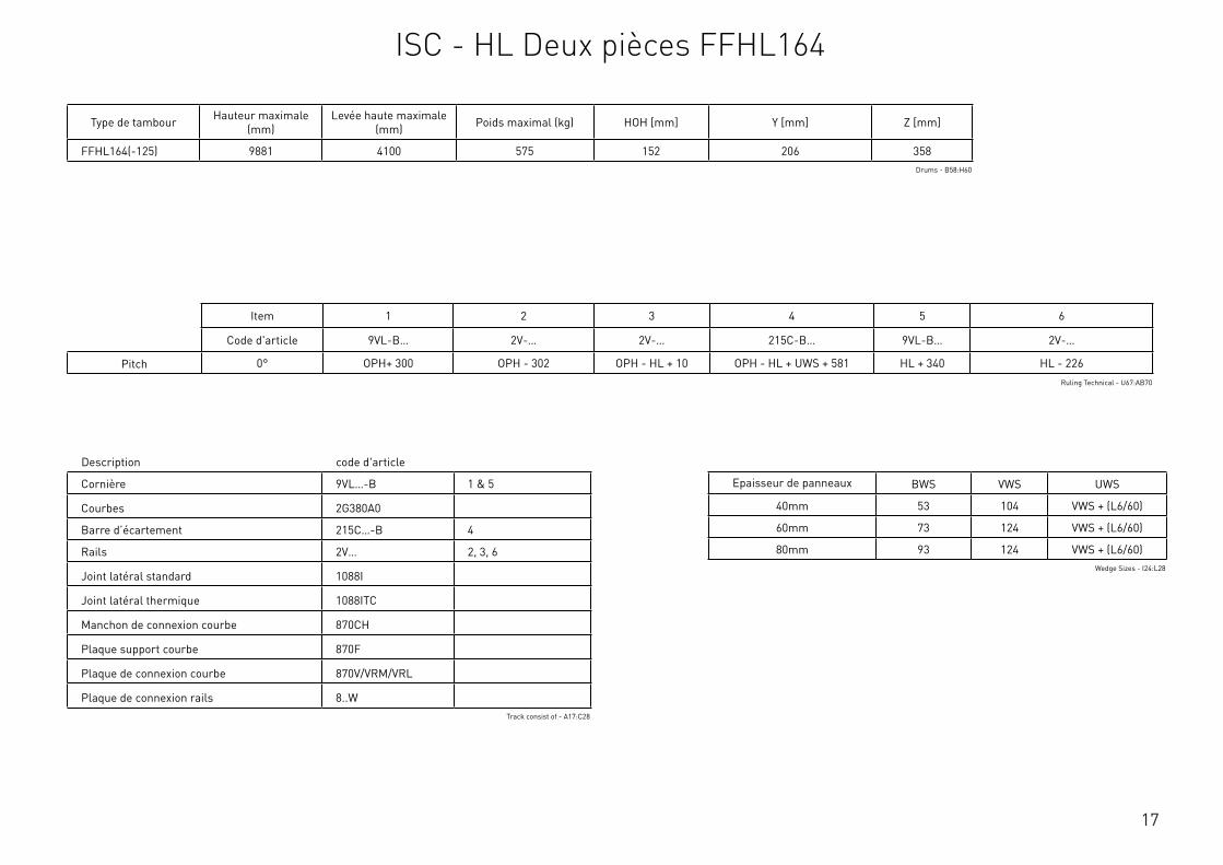
17
Description code d'article
Cornière 9VL…-B 1 & 5
Courbes 2G380A0
Barre d’écartement 215C…-B 4
Rails 2V… 2, 3, 6
Joint latéral standard 1088I
Joint latéral thermique 1088ITC
Manchon de connexion courbe 870CH
Plaque support courbe 870F
Plaque de connexion courbe 870V/VRM/VRL
Plaque de connexion rails 8..WTrack consist of - A17:C28
Type de tambour Hauteur maximale (mm)
Levée haute maximale (mm) Poids maximal (kg) HOH [mm] Y [mm] Z [mm]
FFHL164(-125) 9881 4100 575 152 206 358Drums - B58:H60
Item 1 2 3 4 5 6
Code d'article 9VL-B… 2V-… 2V-… 215C-B… 9VL-B… 2V-…
Pitch 0° OPH+ 300 OPH - 302 OPH - HL + 10 OPH - HL + UWS + 581 HL + 340 HL - 226Ruling Technical - U67:AB70
Epaisseur de panneaux BWS VWS UWS
40mm 53 104 VWS + (L6/60)
60mm 73 124 VWS + (L6/60)
80mm 93 124 VWS + (L6/60)Wedge Sizes - I24:L28
ISC - HL Deux pièces FFHL164

18
Détails du système Min. Max.
Largeur ouverture OPW 1500mm 8500mm
Hauteur ouverture OPH 1830mm 7000mm
système de levée haute HL 210mm 4100mm
Largeur fixation S* 68mm 78mm
Hauteur arbre HL + Y - HL + 206mm
Hauteur de montage HL + Z - HL + 358mm
Pente PITCH 5° 35°
Distance mur-arbre HOH - 127mm
le poids 575kg
Dimension cale supérieure UWS Voir le tableau
Dimension cale inférieure BWS Voir le tableau
Dimension cale variable VWS Voir le tableau
* Selon la sélection de CBD/plaque de base, voir page plaques de baseRequirements & Technical Data - G59:J75
OPH
UWS
HOH
HL
+ Y
BWS
HL
+ Z
PITCH
OPH
OPW
≥S
≥125
≥10
00
≥80
*
HL
+ Y
HL
+ Z
OPH - HL
= = =
HL
VWS
Z
Y
≥250
2
3 4
8
1
65
This
wor
k is
cop
yrig
ht a
nd n
o pa
rt m
ay b
e re
prod
uced
, by
any
proc
ess,
nor
may
any
oth
er e
xclu
sive
righ
t be
exer
cise
d w
ithou
t the
per
mis
sion
of A
SSA
ABLO
Y.
Surface treatment:
V9_2
019_
02_2
1_dr
wRev.:Document ID
Material: General tolerance:
Volume: Mass: Surface area: Created (YYYY-MM-DD): Designed by: Drawn by: Scale: Projection:
Alternate ID450101481.54 mm³ 1:100 (A3)81922696.8 mm²450101.48 gram
ISO 8015ISO 2768-mH
1SHEET 1 OF 1Configuration:ISC-FHL-FFHL164-2Piece
Avec un système de levée haute, la porte se lève verticalement au-dessus de la hauteur d’ouverture (linteau), après quoi le panneau suit la courbe, plus haut dans le bâtiment. Le sytème de levage haut est toujours la distance entre la hauteur d’ouverture de la lumière du jour (linteau) et le bas des rails horizontaux.
Selon la hauteur d’ouverture et le système haut, un espace de hauteur supplémentaire de 308 mm à 358 mm est nécessaire pour positionner le système d’arbre avec les tambours.
ISC - FHL Deux pièces FFHL164
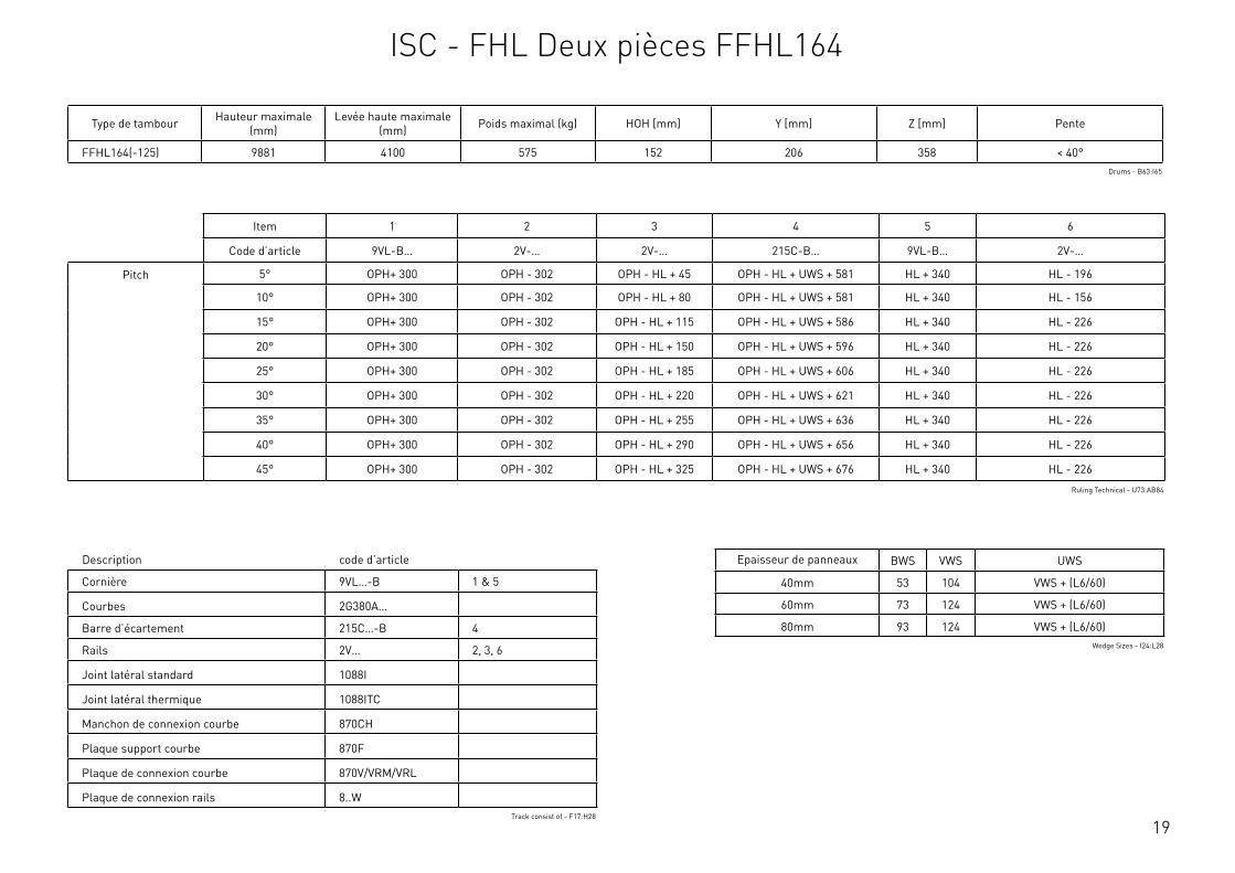
19
Description code d’article
Cornière 9VL…-B 1 & 5
Courbes 2G380A…
Barre d’écartement 215C…-B 4
Rails 2V… 2, 3, 6
Joint latéral standard 1088I
Joint latéral thermique 1088ITC
Manchon de connexion courbe 870CH
Plaque support courbe 870F
Plaque de connexion courbe 870V/VRM/VRL
Plaque de connexion rails 8..WTrack consist of - F17:H28
Type de tambour Hauteur maximale (mm)
Levée haute maximale (mm) Poids maximal (kg) HOH [mm] Y [mm] Z [mm] Pente
FFHL164(-125) 9881 4100 575 152 206 358 < 40°Drums - B63:I65
Item 1 2 3 4 5 6
Code d’article 9VL-B… 2V-… 2V-… 215C-B… 9VL-B… 2V-…
Pitch 5° OPH+ 300 OPH - 302 OPH - HL + 45 OPH - HL + UWS + 581 HL + 340 HL - 196
10° OPH+ 300 OPH - 302 OPH - HL + 80 OPH - HL + UWS + 581 HL + 340 HL - 156
15° OPH+ 300 OPH - 302 OPH - HL + 115 OPH - HL + UWS + 586 HL + 340 HL - 226
20° OPH+ 300 OPH - 302 OPH - HL + 150 OPH - HL + UWS + 596 HL + 340 HL - 226
25° OPH+ 300 OPH - 302 OPH - HL + 185 OPH - HL + UWS + 606 HL + 340 HL - 226
30° OPH+ 300 OPH - 302 OPH - HL + 220 OPH - HL + UWS + 621 HL + 340 HL - 226
35° OPH+ 300 OPH - 302 OPH - HL + 255 OPH - HL + UWS + 636 HL + 340 HL - 226
40° OPH+ 300 OPH - 302 OPH - HL + 290 OPH - HL + UWS + 656 HL + 340 HL - 226
45° OPH+ 300 OPH - 302 OPH - HL + 325 OPH - HL + UWS + 676 HL + 340 HL - 226
Ruling Technical - U73:AB84
Epaisseur de panneaux BWS VWS UWS
40mm 53 104 VWS + (L6/60)
60mm 73 124 VWS + (L6/60)
80mm 93 124 VWS + (L6/60)Wedge Sizes - I24:L28
ISC - FHL Deux pièces FFHL164
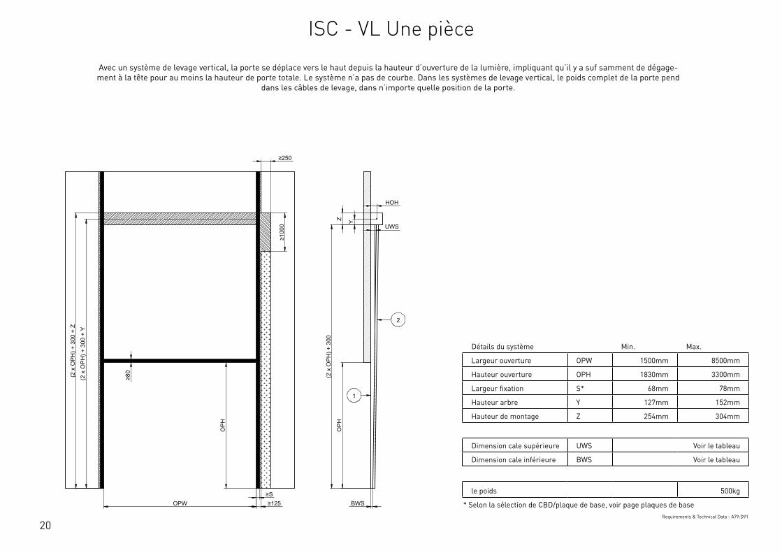
20
Détails du système Min. Max.
Largeur ouverture OPW 1500mm 8500mm
Hauteur ouverture OPH 1830mm 3300mm
Largeur fixation S* 68mm 78mm
Hauteur arbre Y 127mm 152mm
Hauteur de montage Z 254mm 304mm
Dimension cale supérieure UWS Voir le tableau
Dimension cale inférieure BWS Voir le tableau
le poids 500kg
* Selon la sélection de CBD/plaque de base, voir page plaques de baseRequirements & Technical Data - A79:D91
OPH
HOH
Y
BWS
Z
OPH
OPW ≥S ≥125
≥80
≥250
≥10
00
UWS
(2 x
OPH
) + 3
00
(2 x
OPH
) + 3
00 +
Y
(2 x
OPH
) + 3
00 +
Z 2
1
This
wor
k is
cop
yrig
ht a
nd n
o pa
rt m
ay b
e re
prod
uced
, by
any
proc
ess,
nor
may
any
oth
er e
xclu
sive
righ
t be
exer
cise
d w
ithou
t the
per
mis
sion
of A
SSA
ABLO
Y.
Surface treatment:
V9_2
019_
02_2
1_dr
wRev.:Document ID
Material: General tolerance:
Volume: Mass: Surface area: Created (YYYY-MM-DD): Designed by: Drawn by: Scale: Projection:
Alternate ID531320092.93 mm³ 1:100 (A3)90915516.55 mm²531320.09 gram
ISO 8015ISO 2768-mH
1SHEET 1 OF 1Configuration:ISC-VL-1Piece
Avec un système de levage vertical, la porte se déplace vers le haut depuis la hauteur d’ouverture de la lumière, impliquant qu’il y a suf samment de dégage-ment à la tête pour au moins la hauteur de porte totale. Le système n’a pas de courbe. Dans les systèmes de levage vertical, le poids complet de la porte pend
dans les câbles de levage, dans n’importe quelle position de la porte.
ISC - VL Une pièce
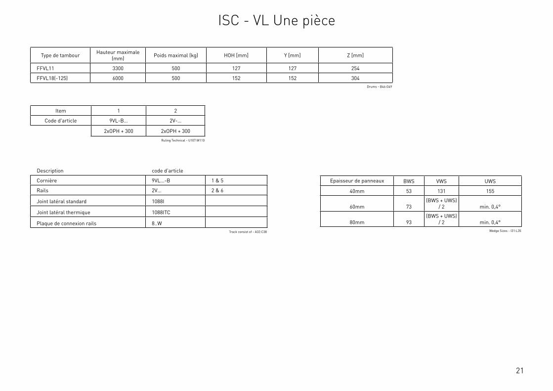
21
Description code d'article
Cornière 9VL…-B 1 & 5
Rails 2V… 2 & 6
Joint latéral standard 1088I
Joint latéral thermique 1088ITC
Plaque de connexion rails 8..WTrack consist of - A32:C38
Type de tambour Hauteur maximale (mm) Poids maximal (kg) HOH [mm] Y [mm] Z [mm]
FFVL11 3300 500 127 127 254
FFVL18(-125) 6000 500 152 152 304Drums - B46:G49
Item 1 2
Code d'article 9VL-B… 2V-…
2xOPH + 300 2xOPH + 300
Ruling Technical - U107:W110
Epaisseur de panneaux BWS VWS UWS
40mm 53 131 155
60mm 73(BWS + UWS)
/ 2 min. 0,4°
80mm 93(BWS + UWS)
/ 2 min. 0,4°Wedge Sizes - I31:L35
ISC - VL Une pièce

22
Détails du système Min. Max.
Largeur ouverture OPW 1500mm 8500mm
Hauteur ouverture OPH 1830mm 6000mm
Largeur fixation S* 68mm 78mm
Hauteur arbre Y - 152mm
Hauteur de montage Z - 304mm
le poids 500kg
* Selon la sélection de CBD/plaque de base, voir page plaques de baseRequirements & Technical Data - A95:D104
OPH
HOH
Y
BWS
Z
OPH
OPW ≥S ≥125
≥80
≥250
≥10
00
UWS
VWS (2
x O
PH) +
300
+ Z
(2 x
OPH
) + 3
00 +
Y
(2 x
OPH
) + 3
00 +
Z
2
1
6
5
This
wor
k is
cop
yrig
ht a
nd n
o pa
rt m
ay b
e re
prod
uced
, by
any
proc
ess,
nor
may
any
oth
er e
xclu
sive
righ
t be
exer
cise
d w
ithou
t the
per
mis
sion
of A
SSA
ABLO
Y.
Surface treatment:
V9_2
019_
02_2
1_dr
wRev.:Document ID
Material: General tolerance:
Volume: Mass: Surface area: Created (YYYY-MM-DD): Designed by: Drawn by: Scale: Projection:
Alternate ID552648112.93 mm³ 1:100 (A3)95351980.55 mm²552648.11 gram
ISO 8015ISO 2768-mH
1SHEET 1 OF 1Configuration:ISC-VL-2Piece
Avec un système de levage vertical, la porte se déplace vers le haut depuis la hauteur d’ouverture de la lumière, impliquant qu’il y a suf samment de dégage-ment à la tête pour au moins la hauteur de porte totale. Le système n’a pas de courbe. Dans les systèmes de levage vertical, le poids complet de la porte pend
dans les câbles de levage, dans n’importe quelle position de la porte.
ISC - VL Deux pièces

23
Description code d'article
Cornière 9VL…-B 1 & 5
Rails 2V… 2 & 6
Joint latéral standard 1088I
Joint latéral thermique 1088ITC
Plaque de connexion rails 8..WTrack consist of - A32:C38
Type de tambour Hauteur maximale (mm) Poids maximal (kg) HOH [mm] Y [mm] Z [mm]
FFVL18(-125) 6000 500 152 152 304Drums - B68:G70
Item 1 2 5 6
Code d'article 9VL-B… 2V-… 9VL-B… 2V-…
OPH + 150 OPH + 148 OPH + 150 OPH + 148
Ruling Technical - U114:Y117
Epaisseur de panneaux BWS VWS UWS
40mm 53 131 155
60mm 73(BWS + UWS)
/ 2 min. 0,4°
80mm 93(BWS + UWS)
/ 2 min. 0,4°Wedge Sizes - I31:L35
ISC - VL Deux pièces
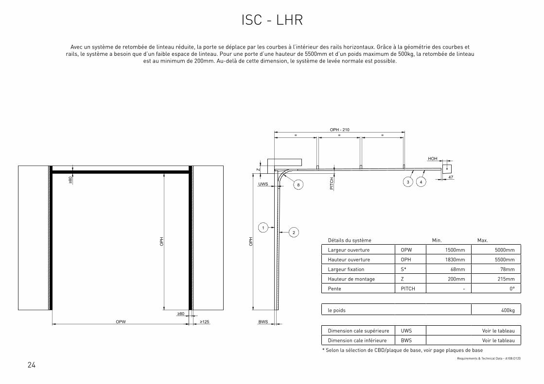
24
Détails du système Min. Max.
Largeur ouverture OPW 1500mm 5000mm
Hauteur ouverture OPH 1830mm 5500mm
Largeur fixation S* 68mm 78mm
Hauteur de montage Z 200mm 215mm
Pente PITCH - 0°
le poids 400kg
Dimension cale supérieure UWS Voir le tableau
Dimension cale inférieure BWS Voir le tableau
* Selon la sélection de CBD/plaque de base, voir page plaques de baseRequirements & Technical Data - A108:D120
OPH
UWS
BWS
PIT
CH
OPW
OPH
≥80
≥80
≥125
HOH
47
= = = OPH - 210
Z
12
3 48
This
wor
k is
cop
yrig
ht a
nd n
o pa
rt m
ay b
e re
prod
uced
, by
any
proc
ess,
nor
may
any
oth
er e
xclu
sive
righ
t be
exer
cise
d w
ithou
t the
per
mis
sion
of A
SSA
ABLO
Y.
Surface treatment:
V9_2
019_
02_2
1_dr
wRev.:Document ID
Material: General tolerance:
Volume: Mass: Surface area: Created (YYYY-MM-DD): Designed by: Drawn by: Scale: Projection:
Alternate ID142976550.27 mm³ 1:100 (A3)25577248.67 mm²142976.55 gram
ISO 8015ISO 2768-mH
1SHEET 1 OF 1Configuration:ISC-LHR
Avec un système de retombée de linteau réduite, la porte se déplace par les courbes à l’intérieur des rails horizontaux. Grâce à la géométrie des courbes et rails, le système a besoin que d’un faible espace de linteau. Pour une porte d’une hauteur de 5500mm et d’un poids maximum de 500kg, la retombée de linteau
est au minimum de 200mm. Au-delà de cette dimension, le système de levée normale est possible.
ISC - LHR
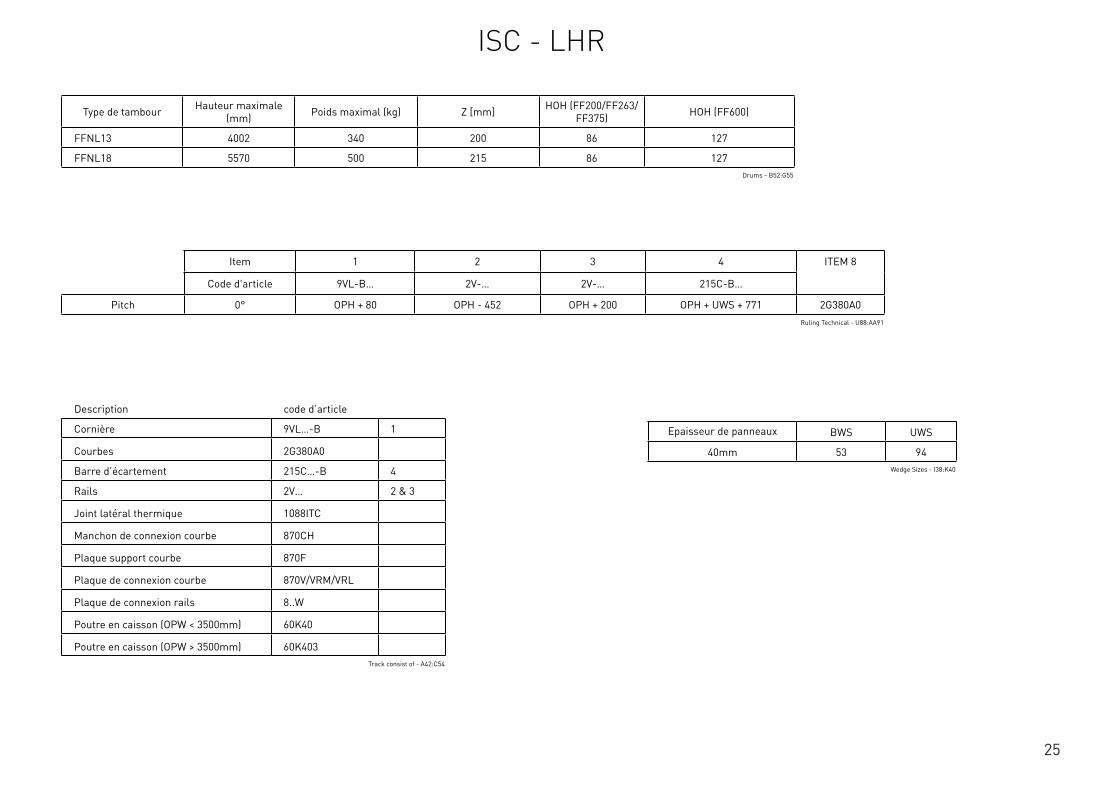
25
Type de tambour Hauteur maximale (mm) Poids maximal (kg) Z [mm] HOH (FF200/FF263/
FF375) HOH (FF600)
FFNL13 4002 340 200 86 127
FFNL18 5570 500 215 86 127Drums - B52:G55
Item 1 2 3 4 ITEM 8
Code d'article 9VL-B… 2V-… 2V-… 215C-B…
Pitch 0° OPH + 80 OPH - 452 OPH + 200 OPH + UWS + 771 2G380A0Ruling Technical - U88:AA91
Epaisseur de panneaux BWS UWS
40mm 53 94Wedge Sizes - I38:K40
Description code d’article
Cornière 9VL…-B 1
Courbes 2G380A0
Barre d’écartement 215C…-B 4
Rails 2V… 2 & 3
Joint latéral thermique 1088ITC
Manchon de connexion courbe 870CH
Plaque support courbe 870F
Plaque de connexion courbe 870V/VRM/VRL
Plaque de connexion rails 8..W
Poutre en caisson (OPW < 3500mm) 60K40
Poutre en caisson (OPW > 3500mm) 60K403Track consist of - A42:C54
ISC - LHR

26
Détails du système Min. Max.
Largeur ouverture OPW 1500mm 5000mm
Hauteur ouverture OPH 1830mm 5500mm
Largeur fixation S* 68mm 78mm
Hauteur de montage Z 200mm 215mm
Pente PITCH 5° 35°
le poids 400kg
Dimension cale supérieure UWS Voir le tableau
Dimension cale inférieure BWS Voir le tableau
* Selon la sélection de CBD/plaque de base, voir page plaques de baseRequirements & Technical Data - G108:J120
OPH
UWS
BWS
PITCH
OPW
OPH
≥80
≥80
≥125
HOH
47
= = = OPH - 210
Z
12
34
8
This
wor
k is
cop
yrig
ht a
nd n
o pa
rt m
ay b
e re
prod
uced
, by
any
proc
ess,
nor
may
any
oth
er e
xclu
sive
righ
t be
exer
cise
d w
ithou
t the
per
mis
sion
of A
SSA
ABLO
Y.
Surface treatment:
V9_2
019_
02_2
1_dr
wRev.:Document ID
Material: General tolerance:
Volume: Mass: Surface area: Created (YYYY-MM-DD): Designed by: Drawn by: Scale: Projection:
Alternate ID142758386.18 mm³ 1:100 (A3)25601845.72 mm²142758.39 gram
ISO 8015ISO 2768-mH
1SHEET 1 OF 1Configuration:ISC-FHR
Avec un système de retombée de linteau réduite, la porte se déplace par les courbes à l’intérieur des rails horizontaux. Grâce à la géométrie des courbes et rails, le système a besoin que d’un faible espace de linteau. Pour une porte d’une hauteur de 5500mm et d’un poids maximum de 500kg, la retombée de linteau
est au minimum de 200mm. Au-delà de cette dimension, le système de levée normale est possible.
ISC - FLH

27
Type de tambour Hauteur maximale (mm) Poids maximal (kg) Z [mm] HOH (FF200/FF263/
FF375) HOH (FF600)
FFNL13 4002 340 200 86 127
FFNL18 5570 500 215 86 127Drums - B52:G55
Item 1 2 3 4 ITEM 8
Code d'article 9VL-B… 2V-… 2V-… 215C-B…
Pitch 10° OPH + 80 OPH - 452 OPH + 270 OPH + UWS + 771 2G380A10
15° OPH + 80 OPH - 422 OPH + 305 OPH + UWS + 776 2G380A15
20° OPH + 80 OPH - 382 OPH + 340 OPH + UWS + 786 2G380A20
25° OPH + 80 OPH - 382 OPH + 375 OPH + UWS + 796 2G380A25
30° OPH + 80 OPH - 360 OPH + 410 OPH + UWS + 811 2G380A30
35° OPH + 80 OPH - 352 OPH + 445 OPH + UWS + 826 2G380A35
Ruling Technical - U95:AA103
Epaisseur de panneaux BWS UWS
40mm 53 94Wedge Sizes - I38:K40
Description code d'article
Cornière 9VL…-B 1
Courbes 2G380A…
Barre d’écartement 215C…-B 4
Rails 2V… 2 & 3
Joint latéral thermique 1088ITC
Manchon de connexion courbe 870CH
Plaque support courbe 870F
Plaque de connexion courbe 870V/VRM/VRL
Plaque de connexion rails 8..W
Poutre en caisson (OPW < 3500mm) 60K40
Poutre en caisson (OPW > 3500mm) 60K403Track consist of - F42:H55
ISC - FLH

28
INFORMATIONS SUR LE SUPPORT INFÉRIEUR
NL / HL / VL LHR
Joint latéral Joint latéral
1088I / 1088ITC 1088ITC
code d’article S [mm] S [mm]Ajoutez pour obtenir un jeu de 5
mm entre le rail et le galet*
425HD 76 - 2066-10
427SX 68 78 2066-07
428TAI 72 78 -
429 68 78 2066-05
429S 68 78 2066-10
440-REGL 76 78 -
440HD 76 - -
440-600 74 78 -
440S 74 78 -
440 74 78 -
444 78 - -
*Le jeu de 5 mm est nécessaire pour le mouvement requis de ±5 mm
Bottom Brackets - A3:D19
E E
F F
SCALE: GENERALROUGHNESS:
PROJECTION:FORMAT: UNIT:
mmTOLERANCES UNLESS
OTHERWISE STATED Acc. To ISO 2768-cK
MATERIAL
TREATMENT
DESCRIPTION
ARTICLE CODE DRAWING NUMBER REVISION
CREATION DATE NETTO WEIGHTCREATED BY
THICKNESS
FLAT WIDTH
FLAT LENGHT
mm
mm
mm
This drawing is property ofFlexiForce
and contains confidentionalinformation.
All rights are strictly reserved.Reproduction
and use for production purposesissue to
third parties in any form whatsoever,is not permitted without written authority from the proprietors.
36 001 001 A
Position of Vertical Angle based on Side Seal and Bottom Bracket
...
JiGa 9-8-2016 538,183 kg
-
A3-
-
---
-C:\V
aultWor
kspa
ce\R
&D\T
eke n
inge
n\36
\360
0100
1\36
001 0
01\4
40 -
108
8I.ia
m
0.5-3 >3-6 >6-30 >30-120 >120-400 >400-1000 >1000-2000 >2000-4000
:
:
:
: :
: : :
: : :
±0.20 ±0.30 ±0.50 ±0.80 ±1.20 ±2.00 ±3.00 ±4.00
Nomi
nal dime
nsion
:
3
A3 Changed values in table, see excel file JiGa 20-01-2017A2 Changed values in table, see excel file JiGa 10-01-2017REV. DESCRIPTION NAME DATE
Side Seal Side Seal 1088I / 1088IT
Bottom Bracket S [mm]Technical S [mm]CommercialAdd to achieve play of 5mm between track and bracket
425HD 75,5 76 2066-10427SX 67,5 68 2066-07428TAI 72 72 -429 67,5 68 2066-05429S 67,5 68 2066-10440-REGL 75,5 76 -440HD 75,5 76 -440-600 73,5 74 -440S 73,5 74 -440 73,5 74 -444 77,5 78 -
S
22,5
1088I
22,5
S
1088ITAcceptable
The play of 5mm is needed for the required pendel of +5mm/-5mm

29
Suspension de rails horizontaux
Utilisez le tableau pour déterminer le nombre requis de profilés de suspension. Distribuez ces profilés uniformément sur une distance de la Hauteur de l’ouverture moins le Lecage haut
(OPH - HL)
Dans le cas d’un système à linteau réduit (LHR & FLH), la poutre en caisson doit être suspendues également POUTRE EN CAISSON: OPW < 3500mm = 60K40 OPW > 3500mm = 60K403 Voir la liste ci-dessous pour déterminer le nombre de profilés de suspension pour la poutre en caisson Distribuez ces profilés uniformément sur la largeur d’ouverture (OPW) de la porte. OPW < 3000: 0 OPW < 5000: 1 OPW < 7000: 2
OPH
BWS
OPH
OPW
≥S
≥125
≥10
00
≥80
*
HL
+ Y
HL
+ Z
OPH - HL
= = = ≥250
12
This
wor
k is
cop
yrig
ht a
nd n
o pa
rt m
ay b
e re
prod
uced
, by
any
proc
ess,
nor
may
any
oth
er e
xclu
sive
righ
t be
exer
cise
d w
ithou
t the
per
mis
sion
of A
SSA
ABLO
Y.
Surface treatment:
V9_2
019_
02_2
1_dr
wRev.:Document ID
Material: General tolerance:
Volume: Mass: Surface area: Created (YYYY-MM-DD): Designed by: Drawn by: Scale: Projection:
Alternate ID415397163.98 mm³ 1:100 (A3)74737484.21 mm²415397.16 gram
ISO 8015ISO 2768-mH
1SHEET 1 OF 1Configuration:ISC-HL-1Piece

30

31
OÙ NOUS TROUVER
FlexiForce B.V. Hanzeweg 19 3771 NG Barneveld PO Box 37 3770 AA Barneveld Pays-Bas +31-(0)342-427777 [email protected]
FlexiForce Hungary Kft. Medvefű str. 24 4031 Debrecen Hongrie +36-52561260 [email protected]
FlexiForce Ibérica, S.L. ApartadoCorreos 403 Ctra. Nacional 332, Km. 211 46780 – Oliva (Valence) Espagne +34 96.285.82.50 [email protected]
FlexiForce Poland Sp. z o.o. Norblina 17/19 95-015 Głowno Pologne +48 426500491 [email protected]
FlexiForce Italia Srl. Via deiTigli CNM 25020 Alfianello Italie +39 0309936510 [email protected]
FlexiForce Turkey Marmara Geri Donusumculer- TopluİsyeriYapıKooperatifi SekerpinarMahallesi AycicekSokakKapi No: 24 (245 ada, 31 parsel) 41420, Çayirova, KOCAELI / TURQUIE +90 262 658 2058 [email protected]
www.flexiforce.com

32
SANTÉ ET SÉCURITÉ AUX INSTALLATIONS DE PORTE!

1
PODRĘCZNIK TECHNICZNYPRZEMYSŁOWY SYSTEM KONSTRUKCYJNY ISC
PL. 3.1

2
WSTĘP
Podręcznik techniczny służy pomocą w zrozumieniu budowy, zawiera szczegóły konstrukcyjne i wymiary przemysłowych systemów prowadzeń ISC FlexiForce dla bram sekcyjnych. Przeznaczony jest nie tylko dla firm samodzielnie produkujących bramy ale także dla tych którzy zlecają ich wykonanie w jednym z od-
działow FlexiForce. W podręczniku tym znajdują się opisy i szczegóły montażu kompletnych zestawów montażowych do budowy bram. Obejmują one wszystkie systemy prowadzeń i wszelkie sytuacje montażowe. Dodane zostały podstawowe informacje o bramach przemysłowych i specyfikacje budowlane.
Aktualne ceny i sposób składania zamówień można znaleźć w oddzielnie opublikowanym Cenniku zestawów montażowych ISC. Odpowiedzi na wszelkie pytania i sugestie oraz wsparcie można uzyskać od właściwych przedstawicieli handlowych , a także na:
www.flexiforce.com
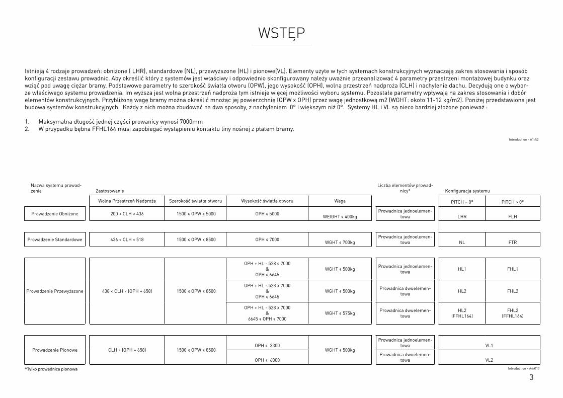
3
WSTĘP
Istnieją 4 rodzaje prowadzeń: obniżone ( LHR), standardowe (NL), przewyższone (HL) i pionowe(VL). Elementy użyte w tych systemach konstrukcyjnych wyznaczają zakres stosowania i sposób konfiguracji zestawu prowadnic. Aby określić który z systemów jest właściwy i odpowiednio skonfigurowany należy uważnie przeanalizować 4 parametry przestrzeni montażowej budynku oraz wziąć pod uwagę ciężar bramy. Podstawowe parametry to szerokość światła otworu (OPW), jego wysokość (OPH), wolna przestrzeń nadproża (CLH) i nachylenie dachu. Decydują one o wybor-ze właściwego systemu prowadzenia. Im wyższa jest wolna przestrzeń nadproża tym istnieje więcej możliwości wyboru systemu. Pozostałe parametry wpływają na zakres stosowania i dobór elementów konstrukcyjnych. Przybliżoną wagę bramy można określić mnożąc jej powierzchnię (OPW x OPH) przez wagę jednostkową m2 (WGHT: około 11-12 kg/m2). Poniżej przedstawiona jest budowa systemów konstrukcyjnych. Każdy z nich można zbudować na dwa sposoby, z nachyleniem 0° i większym niż 0°. Systemy HL i VL są nieco bardziej złożone ponieważ : 1. Maksymalna długość jednej części prowanicy wynosi 7000mm 2. W przypadku bębna FFHL164 musi zapobiegać wystąpieniu kontaktu liny nośnej z płatem bramy.
Introduction - A1:A2
Nazwa systemu prowad-zenia Zastosowanie
Liczba elementów prowad-nicy* Konfiguracja systemu
Wolna Przestrzeń Nadproża Szerokość światła otworu Wysokość światła otworu Waga PITCH = 0° PITCH > 0°
Prowadzenie Obniżone 200 < CLH < 436 1500 ≤ OPW ≤ 5000 OPH ≤ 5000 WEIGHT ≤ 400kgProwadnica jednoelemen-
towa LHR FLH
Prowadzenie Standardowe 436 < CLH < 518 1500 ≤ OPW ≤ 8500 OPH ≤ 7000 WGHT ≤ 700kgProwadnica jednoelemen-
towa NL FTR
Prowadzenie Przewyższone 438 < CLH < (OPH + 658) 1500 ≤ OPW ≤ 8500
OPH + HL - 528 ≤ 7000 &
OPH ≤ 6645WGHT ≤ 500kg Prowadnica jednoelemen-
towa HL1 FHL1
OPH + HL - 528 ≥ 7000 &
OPH ≤ 6645WGHT ≤ 500kg Prowadnica dwuelemen-
towa HL2 FHL2
OPH + HL - 528 ≥ 7000 &
6645 ≤ OPH ≤ 7000WGHT ≤ 575kg Prowadnica dwuelemen-
towaHL2
(FFHL164)FHL2
(FFHL164)
Prowadzenie Pionowe CLH > (OPH + 658) 1500 ≤ OPW ≤ 8500OPH ≤ 3300
WGHT ≤ 500kg
Prowadnica jednoelemen-towa VL1
OPH ≤ 6000Prowadnica dwuelemen-
towa VL2
*Tylko prowadnica pionowa Introduction - A4:K17
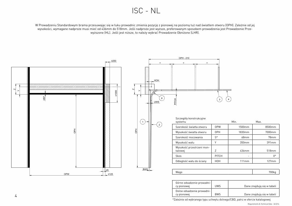
4
Szczegóły konstrukcyjne systemu Min. Max.
Szerokość światła otworu OPW 1500mm 8500mm
Wysokość światła otworu OPH 1830mm 7000mm
Szerokość mocowania S* 68mm 78mm
Wysokość wału Y 350mm 391mm
Wysokość przestrzeni mon-tażowej Z 436mm 518mm
Skos PITCH - 0°
Odległość wału do ściany HOH 111mm 127mm
Waga 700kg
Górne odsadzenie prowadni-cy pionowej UWS Dane znajdują się w tabeli
Dolne odsadzenie prowadni-cy pionowej BWS Dane znajdują się w tabeli
*Zależnie od wybranego typu uchwytu dolnego/CBD, patrz w ofercie katalogowejRequirements & Technical Data - A2:D16
OPH
UWS
HOH
Y
BWS
Z
PIT
CH
OPH
OPW
≥S
≥125
≥10
00
≥80
*
Y Z
OPH - 210
= = = ≥250
12
3 48
This
wor
k is
cop
yrig
ht a
nd n
o pa
rt m
ay b
e re
prod
uced
, by
any
proc
ess,
nor
may
any
oth
er e
xclu
sive
righ
t be
exer
cise
d w
ithou
t the
per
mis
sion
of A
SSA
ABLO
Y.
Surface treatment:
V9_2
019_
02_2
1_dr
wRev.:Document ID
Material: General tolerance:
Volume: Mass: Surface area: Created (YYYY-MM-DD): Designed by: Drawn by: Scale: Projection:
Alternate ID289465723.43 mm³ 1:100 (A3)54462775.75 mm²289465.72 gram
ISO 8015ISO 2768-mH
1SHEET 1 OF 1Configuration:ISC-NL
W Prowadzeniu Standardowym brama przesuwając się w łuku prowadnic zmienia pozycję z pionowej na poziomą tuż nad światłem otworu (OPH). Zależnie od jej wysokości, wymagane nadproże musi mieć od 436mm do 518mm. Jeśli nadproże jest wyższe, preferowanym sposobem prowadzenia jest Prowadzenie Prze-
wyższone (HL). Jeśli jest niższe, to należy wybrać Prowadzenie Obniżone (LHR).
ISC - NL
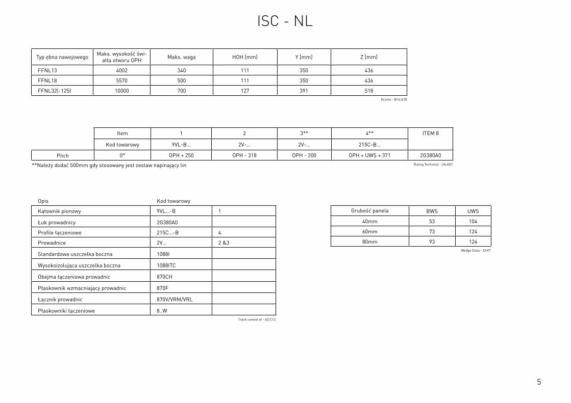
5
Szczegóły konstrukcyjne systemu Min. Max.
Szerokość światła otworu OPW 1500mm 8500mm
Wysokość światła otworu OPH 1830mm 7000mm
Szerokość mocowania S* 68mm 78mm
Wysokość wału Y 350mm 391mm
Wysokość przestrzeni mon-tażowej Z 436mm 518mm
Skos PITCH - 0°
Odległość wału do ściany HOH 111mm 127mm
Waga 700kg
Górne odsadzenie prowadni-cy pionowej UWS Dane znajdują się w tabeli
Dolne odsadzenie prowadni-cy pionowej BWS Dane znajdują się w tabeli
*Zależnie od wybranego typu uchwytu dolnego/CBD, patrz w ofercie katalogowejRequirements & Technical Data - A2:D16
Opis Kod towarowy
Kątownik pionowy 9VL…-B 1
Łuk prowadnicy 2G380A0
Profile łączeniowe 215C…-B 4
Prowadnice 2V… 2 &3
Standardowa uszczelka boczna 1088I
Wysokoizolująca uszczelka boczna 1088ITC
Obejma łączeniowa prowadnic 870CH
Płaskownik wzmacniający prowadnic 870F
Łącznik prowadnic 870V/VRM/VRL
Płaskowniki łączeniowe 8..WTrack consist of - A2:C13
Typ ębna nawojowego Maks. wysokość świ-atła otworu OPH Maks. waga HOH [mm] Y [mm] Z [mm]
FFNL13 4002 340 111 350 436
FFNL18 5570 500 111 350 436
FFNL32(-125) 10000 700 127 391 518Drums - B14:G18
Item 1 2 3** 4** ITEM 8
Kod towarowy 9VL-B… 2V-… 2V-… 215C-B…
Pitch 0° OPH + 250 OPH - 318 OPH - 200 OPH + UWS + 371 2G380A0
**Należy dodać 500mm gdy stosowany jest zestaw napinający lin Ruling Technical - U4:AA7
Grubość panela BWS UWS
40mm 53 104
60mm 73 124
80mm 93 124Wedge Sizes - I3:K7
ISC - NL
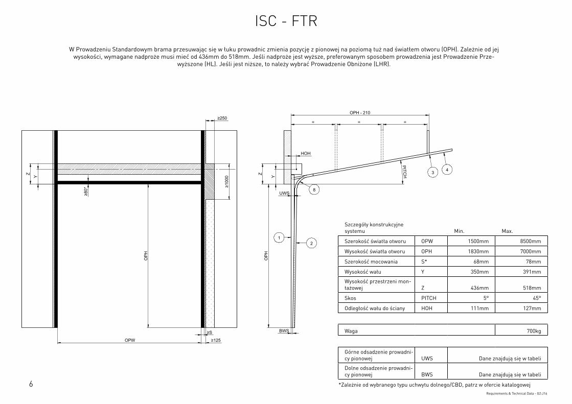
6
Szczegóły konstrukcyjne systemu Min. Max.
Szerokość światła otworu OPW 1500mm 8500mm
Wysokość światła otworu OPH 1830mm 7000mm
Szerokość mocowania S* 68mm 78mm
Wysokość wału Y 350mm 391mm
Wysokość przestrzeni mon-tażowej Z 436mm 518mm
Skos PITCH 5° 45°
Odległość wału do ściany HOH 111mm 127mm
Waga 700kg
Górne odsadzenie prowadni-cy pionowej UWS Dane znajdują się w tabeli
Dolne odsadzenie prowadni-cy pionowej BWS Dane znajdują się w tabeli
*Zależnie od wybranego typu uchwytu dolnego/CBD, patrz w ofercie katalogowejRequirements & Technical Data - G2:J16
OPH
UWS
HOH
Y
BWS
Z
PITCH
OPH
OPW
≥S
≥125
≥10
00
≥80
*
Y Z
OPH - 210
= = = ≥250
12
3 4
8
This
wor
k is
cop
yrig
ht a
nd n
o pa
rt m
ay b
e re
prod
uced
, by
any
proc
ess,
nor
may
any
oth
er e
xclu
sive
righ
t be
exer
cise
d w
ithou
t the
per
mis
sion
of A
SSA
ABLO
Y.
Surface treatment:
V9_2
019_
02_2
1_dr
wRev.:Document ID
Material: General tolerance:
Volume: Mass: Surface area: Created (YYYY-MM-DD): Designed by: Drawn by: Scale: Projection:
Alternate ID289310826.07 mm³ 1:100 (A3)54414606.92 mm²289310.83 gram
ISO 8015ISO 2768-mH
1SHEET 1 OF 1Configuration:ISC-FTR
W Prowadzeniu Standardowym brama przesuwając się w łuku prowadnic zmienia pozycję z pionowej na poziomą tuż nad światłem otworu (OPH). Zależnie od jej wysokości, wymagane nadproże musi mieć od 436mm do 518mm. Jeśli nadproże jest wyższe, preferowanym sposobem prowadzenia jest Prowadzenie Prze-
wyższone (HL). Jeśli jest niższe, to należy wybrać Prowadzenie Obniżone (LHR).
ISC - FTR
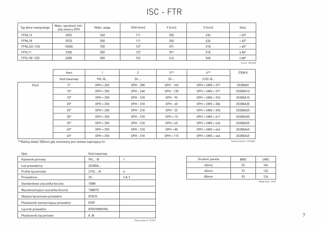
7
Opis Kod towarowy
Kątownik pionowy 9VL…-B 1
Łuk prowadnicy 2G380A…
Profile łączeniowe 215C…-B 4
Prowadnice 2V… 2 & 3
Standardowa uszczelka boczna 1088I
Wysokoizolująca uszczelka boczna 1088ITC
Obejma łączeniowa prowadnic 870CH
Płaskownik wzmacniający prowadnic 870F
Łącznik prowadnic 870V/VRM/VRL
Płaskowniki łączeniowe 8..WTrack consist of - F2:H13
Typ ębna nawojowego Maks. wysokość świ-atła otworu OPH Maks. waga HOH [mm] Y [mm] Z [mm] Skos
FFNL13 4002 340 111 350 436 < 40°
FFNL18 5570 500 111 350 436 < 40°
FFNL32(-125) 10000 700 127 391 518 < 40°
FFVL11 3300 500 127 391 518 ≥ 40°
FFVL18(-125) 6000 500 152 416 568 ≥ 40°Drums - B22:H28
Item 1 2 3** 4** ITEM 8
Kod towarowy 9VL-B… 2V-… 2V-… 215C-B…
Pitch 5° OPH + 250 OPH - 288 OPH - 165 OPH + UWS + 371 2G380A5
10° OPH + 250 OPH - 248 OPH - 130 OPH + UWS + 371 2G380A10
15° OPH + 250 OPH - 318 OPH - 95 OPH + UWS + 376 2G380A15
20° OPH + 250 OPH - 318 OPH - 60 OPH + UWS + 386 2G380A20
25° OPH + 250 OPH - 318 OPH - 25 OPH + UWS + 396 2G380A25
30° OPH + 250 OPH - 318 OPH + 10 OPH + UWS + 411 2G380A30
35° OPH + 250 OPH - 318 OPH + 45 OPH + UWS + 426 2G380A35
40° OPH + 250 OPH - 318 OPH + 80 OPH + UWS + 446 2G380A40
45° OPH + 250 OPH - 318 OPH + 115 OPH + UWS + 466 2G380A45
**Należy dodać 500mm gdy stosowany jest zestaw napinający lin Ruling Technical - U10:AA21
Grubość panela BWS UWS
40mm 53 104
60mm 73 124
80mm 93 124Wedge Sizes - I3:K7
ISC - FTR
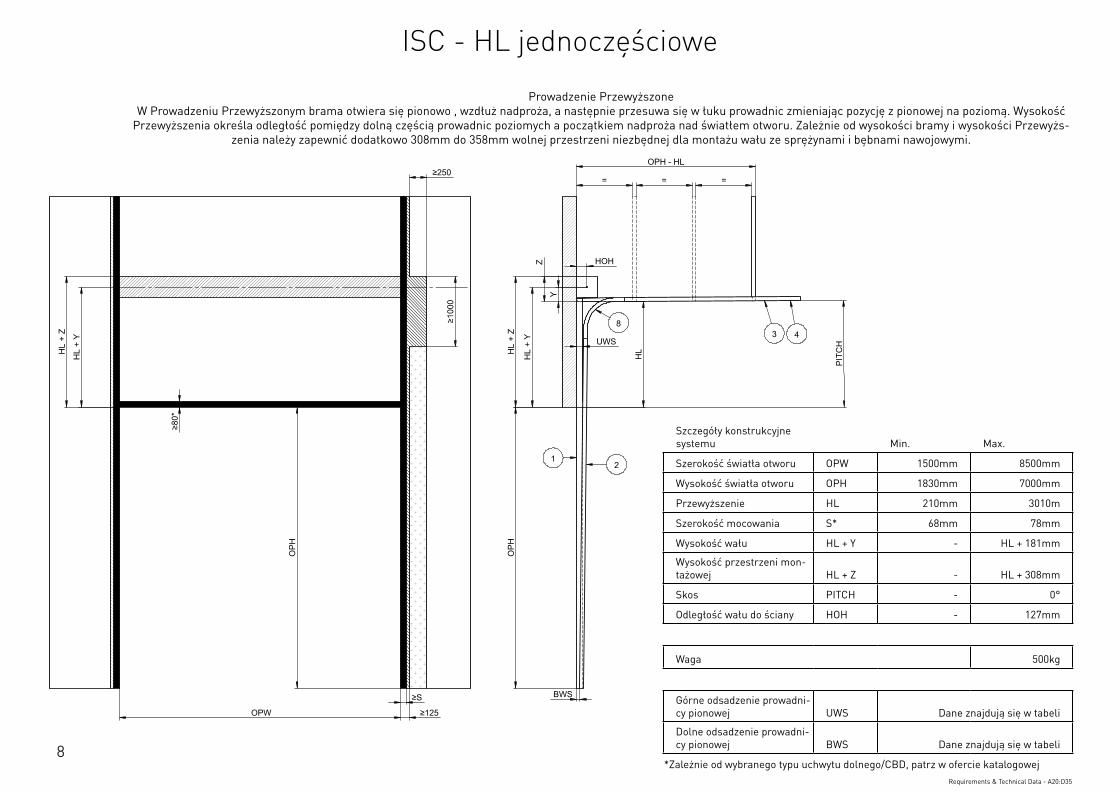
8
Szczegóły konstrukcyjne systemu Min. Max.
Szerokość światła otworu OPW 1500mm 8500mm
Wysokość światła otworu OPH 1830mm 7000mm
Przewyższenie HL 210mm 3010m
Szerokość mocowania S* 68mm 78mm
Wysokość wału HL + Y - HL + 181mm
Wysokość przestrzeni mon-tażowej HL + Z - HL + 308mm
Skos PITCH - 0°
Odległość wału do ściany HOH - 127mm
Waga 500kg
Górne odsadzenie prowadni-cy pionowej UWS Dane znajdują się w tabeli
Dolne odsadzenie prowadni-cy pionowej BWS Dane znajdują się w tabeli
*Zależnie od wybranego typu uchwytu dolnego/CBD, patrz w ofercie katalogowejRequirements & Technical Data - A20:D35
OPH
UWS
HOH
BWS
PIT
CH
OPH
OPW
≥S
≥125
≥10
00
≥80
*
HL
+ Y
HL
+ Z
OPH - HL
= = =
HL
Y
Z
≥250
HL
+ Y
HL
+ Z
12
3 48
This
wor
k is
cop
yrig
ht a
nd n
o pa
rt m
ay b
e re
prod
uced
, by
any
proc
ess,
nor
may
any
oth
er e
xclu
sive
righ
t be
exer
cise
d w
ithou
t the
per
mis
sion
of A
SSA
ABLO
Y.
Surface treatment:
V9_2
019_
02_2
1_dr
wRev.:Document ID
Material: General tolerance:
Volume: Mass: Surface area: Created (YYYY-MM-DD): Designed by: Drawn by: Scale: Projection:
Alternate ID415397163.98 mm³ 1:100 (A3)74737484.21 mm²415397.16 gram
ISO 8015ISO 2768-mH
1SHEET 1 OF 1Configuration:ISC-HL-1Piece
Prowadzenie Przewyższone W Prowadzeniu Przewyższonym brama otwiera się pionowo , wzdłuż nadproża, a następnie przesuwa się w łuku prowadnic zmieniając pozycję z pionowej na poziomą. Wysokość
Przewyższenia określa odległość pomiędzy dolną częścią prowadnic poziomych a początkiem nadproża nad światłem otworu. Zależnie od wysokości bramy i wysokości Przewyżs-zenia należy zapewnić dodatkowo 308mm do 358mm wolnej przestrzeni niezbędnej dla montażu wału ze sprężynami i bębnami nawojowymi.
ISC - HL jednoczęściowe
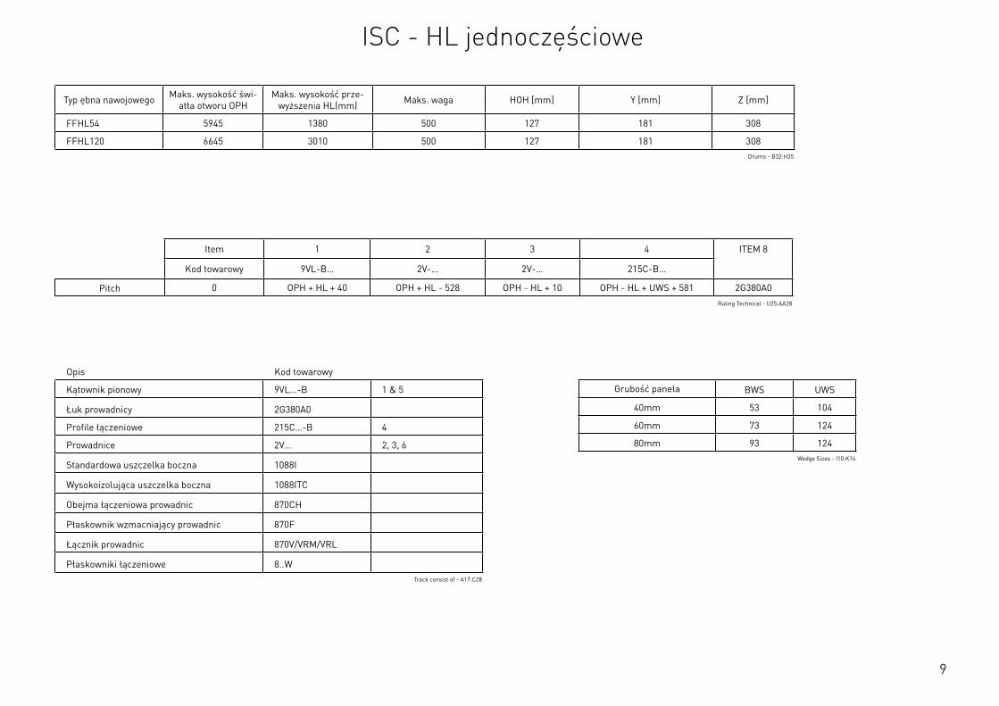
9
Opis Kod towarowy
Kątownik pionowy 9VL…-B 1 & 5
Łuk prowadnicy 2G380A0
Profile łączeniowe 215C…-B 4
Prowadnice 2V… 2, 3, 6
Standardowa uszczelka boczna 1088I
Wysokoizolująca uszczelka boczna 1088ITC
Obejma łączeniowa prowadnic 870CH
Płaskownik wzmacniający prowadnic 870F
Łącznik prowadnic 870V/VRM/VRL
Płaskowniki łączeniowe 8..WTrack consist of - A17:C28
Typ ębna nawojowego Maks. wysokość świ-atła otworu OPH
Maks. wysokość prze-wyższenia HL(mm) Maks. waga HOH [mm] Y [mm] Z [mm]
FFHL54 5945 1380 500 127 181 308
FFHL120 6645 3010 500 127 181 308Drums - B32:H35
Item 1 2 3 4 ITEM 8
Kod towarowy 9VL-B… 2V-… 2V-… 215C-B…
Pitch 0 OPH + HL + 40 OPH + HL - 528 OPH - HL + 10 OPH - HL + UWS + 581 2G380A0Ruling Technical - U25:AA28
Grubość panela BWS UWS
40mm 53 104
60mm 73 124
80mm 93 124Wedge Sizes - I10:K14
ISC - HL jednoczęściowe
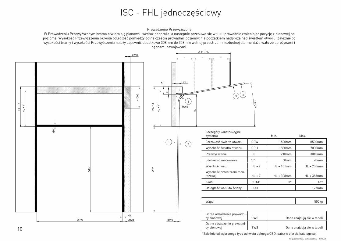
10
Szczegóły konstrukcyjne systemu Min. Max.
Szerokość światła otworu OPW 1500mm 8500mm
Wysokość światła otworu OPH 1830mm 7000mm
Przewyższenie HL 210mm 3010mm
Szerokość mocowania S* 68mm 78mm
Wysokość wału HL + Y HL + 181mm HL + 206mm
Wysokość przestrzeni mon-tażowej HL + Z HL + 308mm HL + 358mm
Skos PITCH 5° 45°
Odległość wału do ściany HOH - 127mm
Waga 500kg
Górne odsadzenie prowadni-cy pionowej UWS Dane znajdują się w tabeli
Dolne odsadzenie prowadni-cy pionowej BWS Dane znajdują się w tabeli
*Zależnie od wybranego typu uchwytu dolnego/CBD, patrz w ofercie katalogowejRequirements & Technical Data - G20:J35
OPH
UWS
HOH
HL
+ Y
BWS
HL
+ Z
PITCH
O
PH
OPW ≥S ≥125
≥10
00
≥80
*
HL
+ Y
HL
+ Z
OPH - HL
= = =
HL
Z
Y
≥250
12
3 4
8
This
wor
k is
cop
yrig
ht a
nd n
o pa
rt m
ay b
e re
prod
uced
, by
any
proc
ess,
nor
may
any
oth
er e
xclu
sive
righ
t be
exer
cise
d w
ithou
t the
per
mis
sion
of A
SSA
ABLO
Y.
Surface treatment:
V9_2
019_
02_2
1_dr
wRev.:Document ID
Material: General tolerance:
Volume: Mass: Surface area: Created (YYYY-MM-DD): Designed by: Drawn by: Scale: Projection:
Alternate ID415364243.14 mm³ 1:100 (A3)74721651.39 mm²415364.24 gram
ISO 8015ISO 2768-mH
1SHEET 1 OF 1Configuration:ISC-FHL-1Piece
Prowadzenie Przewyższone W Prowadzeniu Przewyższonym brama otwiera się pionowo , wzdłuż nadproża, a następnie przesuwa się w łuku prowadnic zmieniając pozycję z pionowej na
poziomą. Wysokość Przewyższenia określa odległość pomiędzy dolną częścią prowadnic poziomych a początkiem nadproża nad światłem otworu. Zależnie od wysokości bramy i wysokości Przewyższenia należy zapewnić dodatkowo 308mm do 358mm wolnej przestrzeni niezbędnej dla montażu wału ze sprężynami i
bębnami nawojowymi.
ISC - FHL jednoczęściowy
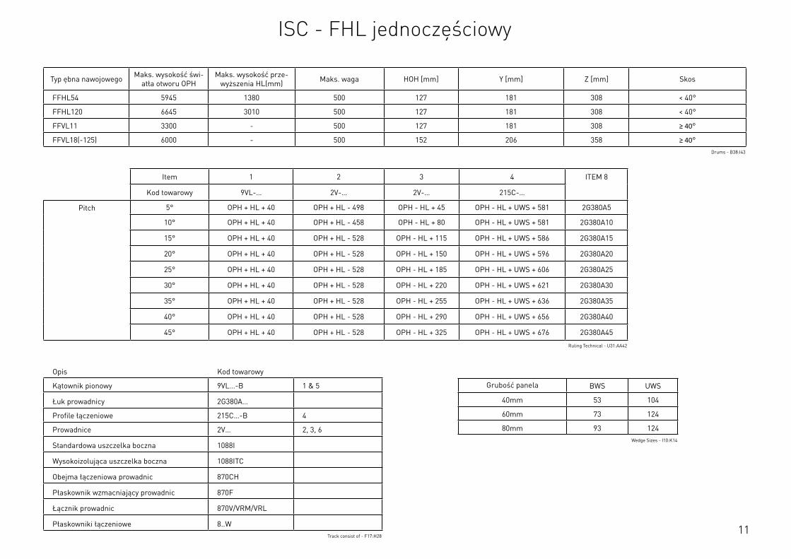
11
Opis Kod towarowy
Kątownik pionowy 9VL…-B 1 & 5
Łuk prowadnicy 2G380A…
Profile łączeniowe 215C…-B 4
Prowadnice 2V… 2, 3, 6
Standardowa uszczelka boczna 1088I
Wysokoizolująca uszczelka boczna 1088ITC
Obejma łączeniowa prowadnic 870CH
Płaskownik wzmacniający prowadnic 870F
Łącznik prowadnic 870V/VRM/VRL
Płaskowniki łączeniowe 8..WTrack consist of - F17:H28
Typ ębna nawojowego Maks. wysokość świ-atła otworu OPH
Maks. wysokość prze-wyższenia HL(mm) Maks. waga HOH [mm] Y [mm] Z [mm] Skos
FFHL54 5945 1380 500 127 181 308 < 40°
FFHL120 6645 3010 500 127 181 308 < 40°
FFVL11 3300 - 500 127 181 308 ≥ 40°
FFVL18(-125) 6000 - 500 152 206 358 ≥ 40°Drums - B38:I43
Item 1 2 3 4 ITEM 8
Kod towarowy 9VL-… 2V-… 2V-… 215C-…
Pitch 5° OPH + HL + 40 OPH + HL - 498 OPH - HL + 45 OPH - HL + UWS + 581 2G380A5
10° OPH + HL + 40 OPH + HL - 458 OPH - HL + 80 OPH - HL + UWS + 581 2G380A10
15° OPH + HL + 40 OPH + HL - 528 OPH - HL + 115 OPH - HL + UWS + 586 2G380A15
20° OPH + HL + 40 OPH + HL - 528 OPH - HL + 150 OPH - HL + UWS + 596 2G380A20
25° OPH + HL + 40 OPH + HL - 528 OPH - HL + 185 OPH - HL + UWS + 606 2G380A25
30° OPH + HL + 40 OPH + HL - 528 OPH - HL + 220 OPH - HL + UWS + 621 2G380A30
35° OPH + HL + 40 OPH + HL - 528 OPH - HL + 255 OPH - HL + UWS + 636 2G380A35
40° OPH + HL + 40 OPH + HL - 528 OPH - HL + 290 OPH - HL + UWS + 656 2G380A40
45° OPH + HL + 40 OPH + HL - 528 OPH - HL + 325 OPH - HL + UWS + 676 2G380A45
Ruling Technical - U31:AA42
Grubość panela BWS UWS
40mm 53 104
60mm 73 124
80mm 93 124Wedge Sizes - I10:K14
ISC - FHL jednoczęściowy
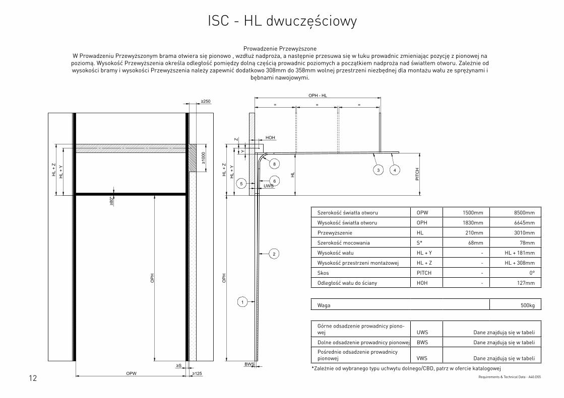
12
Szerokość światła otworu OPW 1500mm 8500mm
Wysokość światła otworu OPH 1830mm 6645mm
Przewyższenie HL 210mm 3010mm
Szerokość mocowania S* 68mm 78mm
Wysokość wału HL + Y - HL + 181mm
Wysokość przestrzeni montażowej HL + Z - HL + 308mm
Skos PITCH - 0°
Odległość wału do ściany HOH - 127mm
Waga 500kg
Górne odsadzenie prowadnicy piono-wej UWS Dane znajdują się w tabeli
Dolne odsadzenie prowadnicy pionowej BWS Dane znajdują się w tabeli
Pośrednie odsadzenie prowadnicy pionowej VWS Dane znajdują się w tabeli
*Zależnie od wybranego typu uchwytu dolnego/CBD, patrz w ofercie katalogowejRequirements & Technical Data - A40:D55
OPH
UWS
HOH
HL
+ Y
BWS
HL
+ Z
PIT
CH
OPH
OPW
≥S
≥125
≥10
00
≥80
*
HL
+ Y
HL
+ Z
OPH - HL
= = =
HL
Y
Z
≥250
2
3 48
1
65
This
wor
k is
cop
yrig
ht a
nd n
o pa
rt m
ay b
e re
prod
uced
, by
any
proc
ess,
nor
may
any
oth
er e
xclu
sive
righ
t be
exer
cise
d w
ithou
t the
per
mis
sion
of A
SSA
ABLO
Y.
Surface treatment:
V9_2
019_
02_2
1_dr
wRev.:Document ID
Material: General tolerance:
Volume: Mass: Surface area: Created (YYYY-MM-DD): Designed by: Drawn by: Scale: Projection:
Alternate ID488235193.04 mm³ 1:100 (A3)89835498.33 mm²488235.19 gram
ISO 8015ISO 2768-mH
1SHEET 1 OF 1Configuration:ISC-HL-2Piece
Prowadzenie Przewyższone W Prowadzeniu Przewyższonym brama otwiera się pionowo , wzdłuż nadproża, a następnie przesuwa się w łuku prowadnic zmieniając pozycję z pionowej na
poziomą. Wysokość Przewyższenia określa odległość pomiędzy dolną częścią prowadnic poziomych a początkiem nadproża nad światłem otworu. Zależnie od wysokości bramy i wysokości Przewyższenia należy zapewnić dodatkowo 308mm do 358mm wolnej przestrzeni niezbędnej dla montażu wału ze sprężynami i
bębnami nawojowymi.
ISC - HL dwuczęściowy
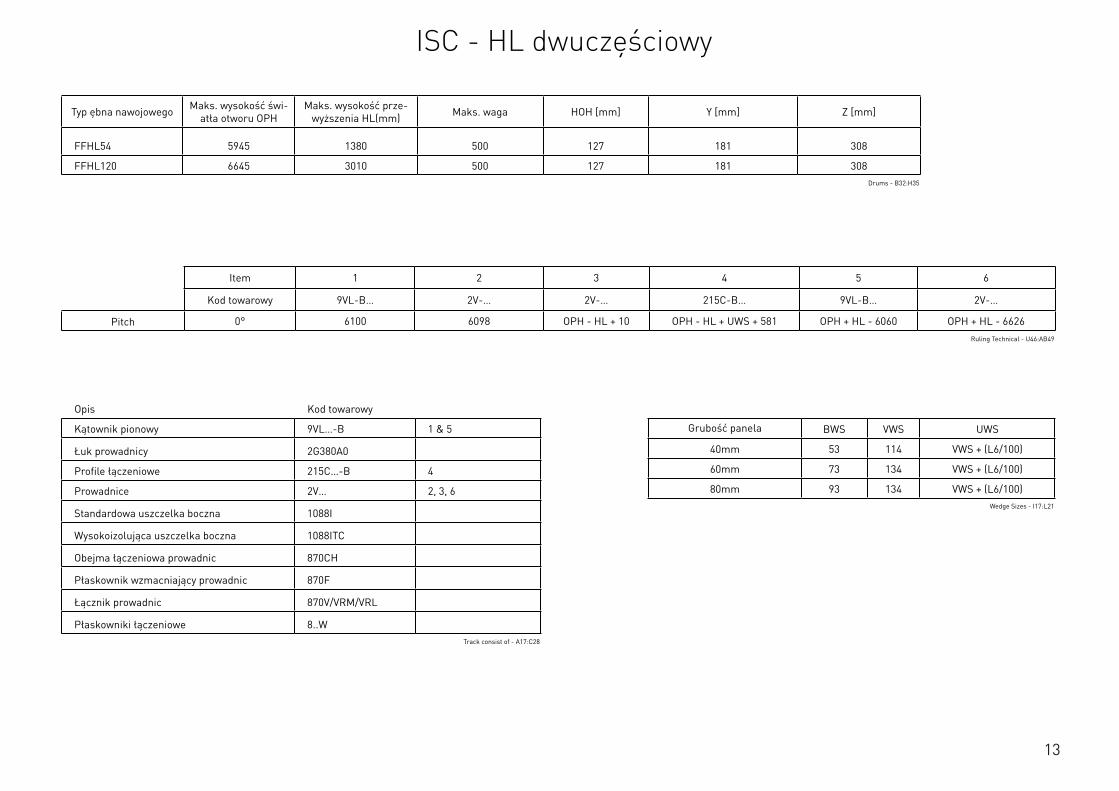
13
Szerokość światła otworu OPW 1500mm 8500mm
Wysokość światła otworu OPH 1830mm 6645mm
Przewyższenie HL 210mm 3010mm
Szerokość mocowania S* 68mm 78mm
Wysokość wału HL + Y - HL + 181mm
Wysokość przestrzeni montażowej HL + Z - HL + 308mm
Skos PITCH - 0°
Odległość wału do ściany HOH - 127mm
Waga 500kg
Górne odsadzenie prowadnicy piono-wej UWS Dane znajdują się w tabeli
Dolne odsadzenie prowadnicy pionowej BWS Dane znajdują się w tabeli
Pośrednie odsadzenie prowadnicy pionowej VWS Dane znajdują się w tabeli
*Zależnie od wybranego typu uchwytu dolnego/CBD, patrz w ofercie katalogowejRequirements & Technical Data - A40:D55
Opis Kod towarowy
Kątownik pionowy 9VL…-B 1 & 5
Łuk prowadnicy 2G380A0
Profile łączeniowe 215C…-B 4
Prowadnice 2V… 2, 3, 6
Standardowa uszczelka boczna 1088I
Wysokoizolująca uszczelka boczna 1088ITC
Obejma łączeniowa prowadnic 870CH
Płaskownik wzmacniający prowadnic 870F
Łącznik prowadnic 870V/VRM/VRL
Płaskowniki łączeniowe 8..WTrack consist of - A17:C28
Typ ębna nawojowego Maks. wysokość świ-atła otworu OPH
Maks. wysokość prze-wyższenia HL(mm) Maks. waga HOH [mm] Y [mm] Z [mm]
FFHL54 5945 1380 500 127 181 308
FFHL120 6645 3010 500 127 181 308Drums - B32:H35
Item 1 2 3 4 5 6
Kod towarowy 9VL-B… 2V-… 2V-… 215C-B… 9VL-B… 2V-…
Pitch 0° 6100 6098 OPH - HL + 10 OPH - HL + UWS + 581 OPH + HL - 6060 OPH + HL - 6626Ruling Technical - U46:AB49
Grubość panela BWS VWS UWS
40mm 53 114 VWS + (L6/100)
60mm 73 134 VWS + (L6/100)
80mm 93 134 VWS + (L6/100)Wedge Sizes - I17:L21
ISC - HL dwuczęściowy
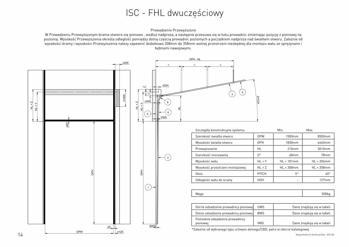
14
Szczegóły konstrukcyjne systemu Min. Max.
Szerokość światła otworu OPW 1500mm 8500mm
Wysokość światła otworu OPH 1830mm 6645mm
Przewyższenie HL 210mm 3010mm
Szerokość mocowania S* 68mm 78mm
Wysokość wału HL + Y HL + 181mm HL + 206mm
Wysokość przestrzeni montażowej HL + Z HL + 308mm HL + 358mm
Skos PITCH 5° 45°
Odległość wału do ściany HOH - 127mm
Waga 500kg
Górne odsadzenie prowadnicy pionowej UWS Dane znajdują się w tabeli
Dolne odsadzenie prowadnicy pionowej BWS Dane znajdują się w tabeli
Pośrednie odsadzenie prowadnicy pionowej VWS Dane znajdują się w tabeli
*Zależnie od wybranego typu uchwytu dolnego/CBD, patrz w ofercie katalogowejRequirements & Technical Data - G39:J55
OPH
UWS
HOH
HL
+ Y
BWS
HL
+ Z
PITCH
O
PH
OPW
≥S
≥125
≥10
00
≥80
*
HL
+ Y
HL
+ Z
OPH - HL
= = =
HL
VWS
Z
Y
≥250
2
34
8
1
65
This
wor
k is
cop
yrig
ht a
nd n
o pa
rt m
ay b
e re
prod
uced
, by
any
proc
ess,
nor
may
any
oth
er e
xclu
sive
righ
t be
exer
cise
d w
ithou
t the
per
mis
sion
of A
SSA
ABLO
Y.
Surface treatment:
V9_2
019_
02_2
1_dr
wRev.:Document ID
Material: General tolerance:
Volume: Mass: Surface area: Created (YYYY-MM-DD): Designed by: Drawn by: Scale: Projection:
Alternate ID488036705.35 mm³ 1:100 (A3)89774518.55 mm²488036.71 gram
ISO 8015ISO 2768-mH
1SHEET 1 OF 1Configuration:ISC-FHL-2Piece
Prowadzenie Przewyższone W Prowadzeniu Przewyższonym brama otwiera się pionowo , wzdłuż nadproża, a następnie przesuwa się w łuku prowadnic zmieniając pozycję z pionowej na
poziomą. Wysokość Przewyższenia określa odległość pomiędzy dolną częścią prowadnic poziomych a początkiem nadproża nad światłem otworu. Zależnie od wysokości bramy i wysokości Przewyższenia należy zapewnić dodatkowo 308mm do 358mm wolnej przestrzeni niezbędnej dla montażu wału ze sprężynami i
bębnami nawojowymi.
ISC - FHL dwuczęściowy
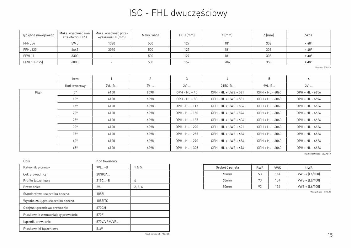
15
Opis Kod towarowy
Kątownik pionowy 9VL…-B 1 & 5
Łuk prowadnicy 2G380A…
Profile łączeniowe 215C…-B 4
Prowadnice 2V… 2, 3, 6
Standardowa uszczelka boczna 1088I
Wysokoizolująca uszczelka boczna 1088ITC
Obejma łączeniowa prowadnic 870CH
Płaskownik wzmacniający prowadnic 870F
Łącznik prowadnic 870V/VRM/VRL
Płaskowniki łączeniowe 8..WTrack consist of - F17:H28
Typ ębna nawojowego Maks. wysokość świ-atła otworu OPH
Maks. wysokość prze-wyższenia HL(mm) Maks. waga HOH [mm] Y [mm] Z [mm] Skos
FFHL54 5945 1380 500 127 181 308 < 40°
FFHL120 6645 3010 500 127 181 308 < 40°
FFVL11 3300 - 500 127 181 308 ≥ 40°
FFVL18(-125) 6000 - 500 152 206 358 ≥ 40°Drums - B38:I43
Item 1 2 3 4 5 6
Kod towarowy 9VL-B… 2V-… 2V-… 215C-B… 9VL-B… 2V-…
Pitch 5° 6100 6098 OPH - HL + 45 OPH - HL + UWS + 581 OPH + HL - 6060 OPH + HL - 6656
10° 6100 6098 OPH - HL + 80 OPH - HL + UWS + 581 OPH + HL - 6060 OPH + HL - 6696
15° 6100 6098 OPH - HL + 115 OPH - HL + UWS + 586 OPH + HL - 6060 OPH + HL - 6626
20° 6100 6098 OPH - HL + 150 OPH - HL + UWS + 596 OPH + HL - 6060 OPH + HL - 6626
25° 6100 6098 OPH - HL + 185 OPH - HL + UWS + 606 OPH + HL - 6060 OPH + HL - 6626
30° 6100 6098 OPH - HL + 220 OPH - HL + UWS + 621 OPH + HL - 6060 OPH + HL - 6626
35° 6100 6098 OPH - HL + 255 OPH - HL + UWS + 636 OPH + HL - 6060 OPH + HL - 6626
40° 6100 6098 OPH - HL + 290 OPH - HL + UWS + 656 OPH + HL - 6060 OPH + HL - 6626
45° 6100 6098 OPH - HL + 325 OPH - HL + UWS + 676 OPH + HL - 6060 OPH + HL - 6626
Ruling Technical - U52:AB63
Grubość panela BWS VWS UWS
40mm 53 114 VWS + (L6/100)
60mm 73 134 VWS + (L6/100)
80mm 93 134 VWS + (L6/100)Wedge Sizes - I17:L21
ISC - FHL dwuczęściowy
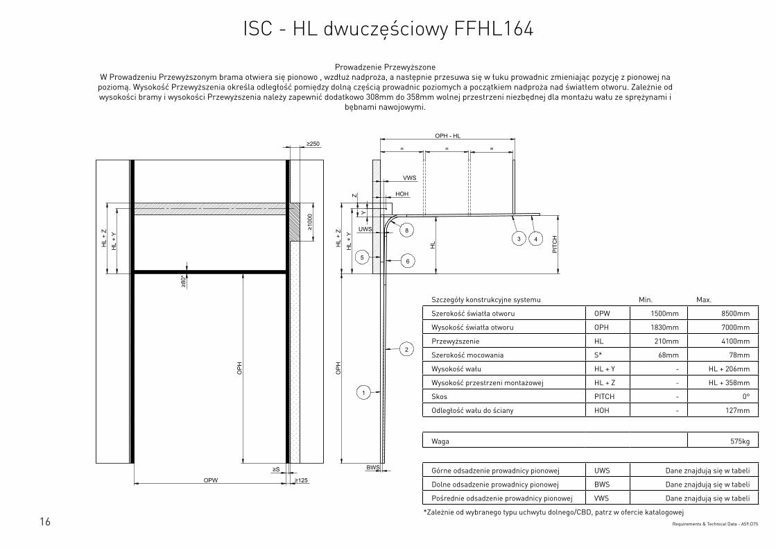
16
Szczegóły konstrukcyjne systemu Min. Max.
Szerokość światła otworu OPW 1500mm 8500mm
Wysokość światła otworu OPH 1830mm 7000mm
Przewyższenie HL 210mm 4100mm
Szerokość mocowania S* 68mm 78mm
Wysokość wału HL + Y - HL + 206mm
Wysokość przestrzeni montażowej HL + Z - HL + 358mm
Skos PITCH - 0°
Odległość wału do ściany HOH - 127mm
Waga 575kg
Górne odsadzenie prowadnicy pionowej UWS Dane znajdują się w tabeli
Dolne odsadzenie prowadnicy pionowej BWS Dane znajdują się w tabeli
Pośrednie odsadzenie prowadnicy pionowej VWS Dane znajdują się w tabeli
*Zależnie od wybranego typu uchwytu dolnego/CBD, patrz w ofercie katalogowejRequirements & Technical Data - A59:D75
OPH
UWS
HOH
HL
+ Y
BWS
HL
+ Z
PIT
CH
OPH
OPW
≥S
≥125
≥10
00
≥80
*
HL
+ Y
HL
+ Z
OPH - HL
= = =
HL
VWS
Y
Z
≥250
2
3 48
1
65
This
wor
k is
cop
yrig
ht a
nd n
o pa
rt m
ay b
e re
prod
uced
, by
any
proc
ess,
nor
may
any
oth
er e
xclu
sive
righ
t be
exer
cise
d w
ithou
t the
per
mis
sion
of A
SSA
ABLO
Y.
Surface treatment:
V9_2
019_
02_2
1_dr
wRev.:Document ID
Material: General tolerance:
Volume: Mass: Surface area: Created (YYYY-MM-DD): Designed by: Drawn by: Scale: Projection:
Alternate ID450571832.56 mm³ 1:100 (A3)82034869.87 mm²450571.83 gram
ISO 8015ISO 2768-mH
1SHEET 1 OF 1Configuration:ISC-HL-FFHL164-2Piece
Prowadzenie Przewyższone W Prowadzeniu Przewyższonym brama otwiera się pionowo , wzdłuż nadproża, a następnie przesuwa się w łuku prowadnic zmieniając pozycję z pionowej na
poziomą. Wysokość Przewyższenia określa odległość pomiędzy dolną częścią prowadnic poziomych a początkiem nadproża nad światłem otworu. Zależnie od wysokości bramy i wysokości Przewyższenia należy zapewnić dodatkowo 308mm do 358mm wolnej przestrzeni niezbędnej dla montażu wału ze sprężynami i
bębnami nawojowymi.
ISC - HL dwuczęściowy FFHL164
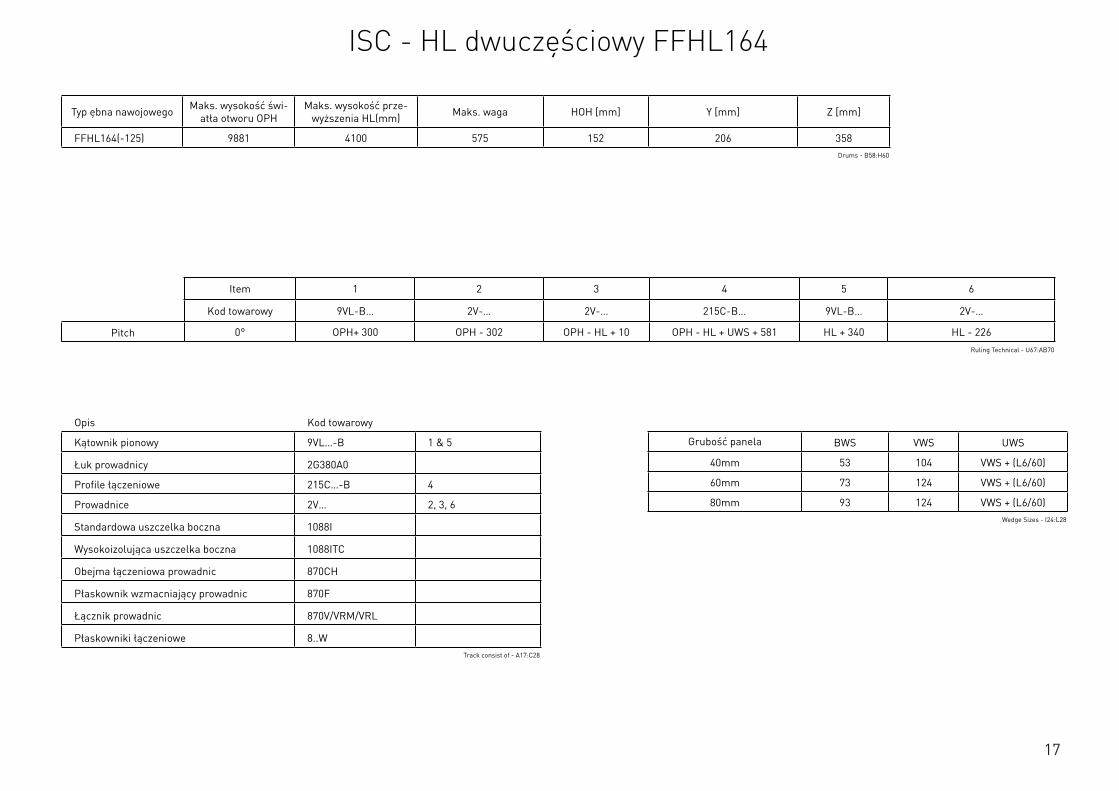
17
Szczegóły konstrukcyjne systemu Min. Max.
Szerokość światła otworu OPW 1500mm 8500mm
Wysokość światła otworu OPH 1830mm 7000mm
Przewyższenie HL 210mm 4100mm
Szerokość mocowania S* 68mm 78mm
Wysokość wału HL + Y - HL + 206mm
Wysokość przestrzeni montażowej HL + Z - HL + 358mm
Skos PITCH - 0°
Odległość wału do ściany HOH - 127mm
Waga 575kg
Górne odsadzenie prowadnicy pionowej UWS Dane znajdują się w tabeli
Dolne odsadzenie prowadnicy pionowej BWS Dane znajdują się w tabeli
Pośrednie odsadzenie prowadnicy pionowej VWS Dane znajdują się w tabeli
*Zależnie od wybranego typu uchwytu dolnego/CBD, patrz w ofercie katalogowejRequirements & Technical Data - A59:D75
Opis Kod towarowy
Kątownik pionowy 9VL…-B 1 & 5
Łuk prowadnicy 2G380A0
Profile łączeniowe 215C…-B 4
Prowadnice 2V… 2, 3, 6
Standardowa uszczelka boczna 1088I
Wysokoizolująca uszczelka boczna 1088ITC
Obejma łączeniowa prowadnic 870CH
Płaskownik wzmacniający prowadnic 870F
Łącznik prowadnic 870V/VRM/VRL
Płaskowniki łączeniowe 8..WTrack consist of - A17:C28
Typ ębna nawojowego Maks. wysokość świ-atła otworu OPH
Maks. wysokość prze-wyższenia HL(mm) Maks. waga HOH [mm] Y [mm] Z [mm]
FFHL164(-125) 9881 4100 575 152 206 358Drums - B58:H60
Item 1 2 3 4 5 6
Kod towarowy 9VL-B… 2V-… 2V-… 215C-B… 9VL-B… 2V-…
Pitch 0° OPH+ 300 OPH - 302 OPH - HL + 10 OPH - HL + UWS + 581 HL + 340 HL - 226Ruling Technical - U67:AB70
Grubość panela BWS VWS UWS
40mm 53 104 VWS + (L6/60)
60mm 73 124 VWS + (L6/60)
80mm 93 124 VWS + (L6/60)Wedge Sizes - I24:L28
ISC - HL dwuczęściowy FFHL164
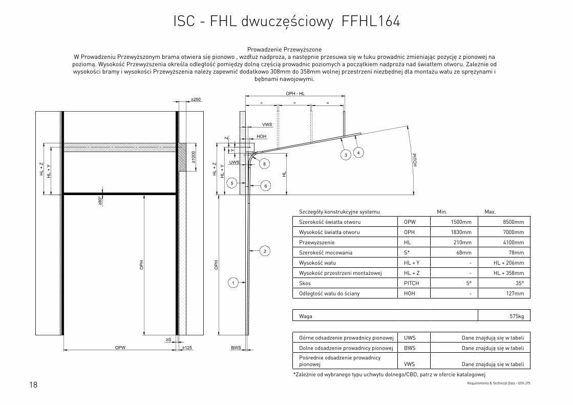
18
Szczegóły konstrukcyjne systemu Min. Max.
Szerokość światła otworu OPW 1500mm 8500mm
Wysokość światła otworu OPH 1830mm 7000mm
Przewyższenie HL 210mm 4100mm
Szerokość mocowania S* 68mm 78mm
Wysokość wału HL + Y - HL + 206mm
Wysokość przestrzeni montażowej HL + Z - HL + 358mm
Skos PITCH 5° 35°
Odległość wału do ściany HOH - 127mm
Waga 575kg
Górne odsadzenie prowadnicy pionowej UWS Dane znajdują się w tabeli
Dolne odsadzenie prowadnicy pionowej BWS Dane znajdują się w tabeli
Pośrednie odsadzenie prowadnicy pionowej VWS Dane znajdują się w tabeli
*Zależnie od wybranego typu uchwytu dolnego/CBD, patrz w ofercie katalogowejRequirements & Technical Data - G59:J75
OPH
UWS
HOH
HL
+ Y
BWS
HL
+ Z
PITCH
OPH
OPW
≥S
≥125
≥10
00
≥80
*
HL
+ Y
HL
+ Z
OPH - HL
= = =
HL
VWS
Z
Y
≥250
2
3 4
8
1
65
This
wor
k is
cop
yrig
ht a
nd n
o pa
rt m
ay b
e re
prod
uced
, by
any
proc
ess,
nor
may
any
oth
er e
xclu
sive
righ
t be
exer
cise
d w
ithou
t the
per
mis
sion
of A
SSA
ABLO
Y.
Surface treatment:
V9_2
019_
02_2
1_dr
wRev.:Document ID
Material: General tolerance:
Volume: Mass: Surface area: Created (YYYY-MM-DD): Designed by: Drawn by: Scale: Projection:
Alternate ID450101481.54 mm³ 1:100 (A3)81922696.8 mm²450101.48 gram
ISO 8015ISO 2768-mH
1SHEET 1 OF 1Configuration:ISC-FHL-FFHL164-2Piece
Prowadzenie Przewyższone W Prowadzeniu Przewyższonym brama otwiera się pionowo , wzdłuż nadproża, a następnie przesuwa się w łuku prowadnic zmieniając pozycję z pionowej na
poziomą. Wysokość Przewyższenia określa odległość pomiędzy dolną częścią prowadnic poziomych a początkiem nadproża nad światłem otworu. Zależnie od wysokości bramy i wysokości Przewyższenia należy zapewnić dodatkowo 308mm do 358mm wolnej przestrzeni niezbędnej dla montażu wału ze sprężynami i
bębnami nawojowymi.
ISC - FHL dwuczęściowy FFHL164
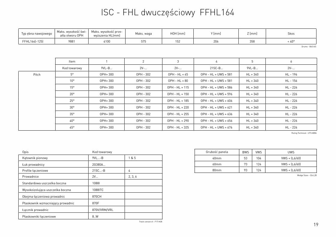
19
Opis Kod towarowy
Kątownik pionowy 9VL…-B 1 & 5
Łuk prowadnicy 2G380A…
Profile łączeniowe 215C…-B 4
Prowadnice 2V… 2, 3, 6
Standardowa uszczelka boczna 1088I
Wysokoizolująca uszczelka boczna 1088ITC
Obejma łączeniowa prowadnic 870CH
Płaskownik wzmacniający prowadnic 870F
Łącznik prowadnic 870V/VRM/VRL
Płaskowniki łączeniowe 8..WTrack consist of - F17:H28
Typ ębna nawojowego Maks. wysokość świ-atła otworu OPH
Maks. wysokość prze-wyższenia HL(mm) Maks. waga HOH [mm] Y [mm] Z [mm] Skos
FFHL164(-125) 9881 4100 575 152 206 358 < 40°Drums - B63:I65
Item 1 2 3 4 5 6
Kod towarowy 9VL-B… 2V-… 2V-… 215C-B… 9VL-B… 2V-…
Pitch 5° OPH+ 300 OPH - 302 OPH - HL + 45 OPH - HL + UWS + 581 HL + 340 HL - 196
10° OPH+ 300 OPH - 302 OPH - HL + 80 OPH - HL + UWS + 581 HL + 340 HL - 156
15° OPH+ 300 OPH - 302 OPH - HL + 115 OPH - HL + UWS + 586 HL + 340 HL - 226
20° OPH+ 300 OPH - 302 OPH - HL + 150 OPH - HL + UWS + 596 HL + 340 HL - 226
25° OPH+ 300 OPH - 302 OPH - HL + 185 OPH - HL + UWS + 606 HL + 340 HL - 226
30° OPH+ 300 OPH - 302 OPH - HL + 220 OPH - HL + UWS + 621 HL + 340 HL - 226
35° OPH+ 300 OPH - 302 OPH - HL + 255 OPH - HL + UWS + 636 HL + 340 HL - 226
40° OPH+ 300 OPH - 302 OPH - HL + 290 OPH - HL + UWS + 656 HL + 340 HL - 226
45° OPH+ 300 OPH - 302 OPH - HL + 325 OPH - HL + UWS + 676 HL + 340 HL - 226
Ruling Technical - U73:AB84
Grubość panela BWS VWS UWS
40mm 53 104 VWS + (L6/60)
60mm 73 124 VWS + (L6/60)
80mm 93 124 VWS + (L6/60)Wedge Sizes - I24:L28
ISC - FHL dwuczęściowy FFHL164
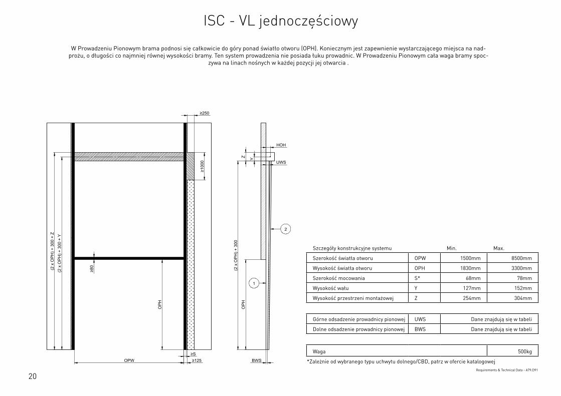
20
Szczegóły konstrukcyjne systemu Min. Max.
Szerokość światła otworu OPW 1500mm 8500mm
Wysokość światła otworu OPH 1830mm 3300mm
Szerokość mocowania S* 68mm 78mm
Wysokość wału Y 127mm 152mm
Wysokość przestrzeni montażowej Z 254mm 304mm
Górne odsadzenie prowadnicy pionowej UWS Dane znajdują się w tabeli
Dolne odsadzenie prowadnicy pionowej BWS Dane znajdują się w tabeli
Waga 500kg
*Zależnie od wybranego typu uchwytu dolnego/CBD, patrz w ofercie katalogowejRequirements & Technical Data - A79:D91
OPH
HOH
Y
BWS
Z
OPH
OPW ≥S ≥125
≥80
≥250
≥10
00
UWS
(2 x
OPH
) + 3
00
(2 x
OPH
) + 3
00 +
Y
(2 x
OPH
) + 3
00 +
Z 2
1
This
wor
k is
cop
yrig
ht a
nd n
o pa
rt m
ay b
e re
prod
uced
, by
any
proc
ess,
nor
may
any
oth
er e
xclu
sive
righ
t be
exer
cise
d w
ithou
t the
per
mis
sion
of A
SSA
ABLO
Y.
Surface treatment:
V9_2
019_
02_2
1_dr
wRev.:Document ID
Material: General tolerance:
Volume: Mass: Surface area: Created (YYYY-MM-DD): Designed by: Drawn by: Scale: Projection:
Alternate ID531320092.93 mm³ 1:100 (A3)90915516.55 mm²531320.09 gram
ISO 8015ISO 2768-mH
1SHEET 1 OF 1Configuration:ISC-VL-1Piece
W Prowadzeniu Pionowym brama podnosi się całkowicie do góry ponad światło otworu (OPH). Koniecznym jest zapewnienie wystarczającego miejsca na nad-prożu, o długości co najmniej równej wysokości bramy. Ten system prowadzenia nie posiada łuku prowadnic. W Prowadzeniu Pionowym cała waga bramy spoc-
zywa na linach nośnych w każdej pozycji jej otwarcia .
ISC - VL jednoczęściowy
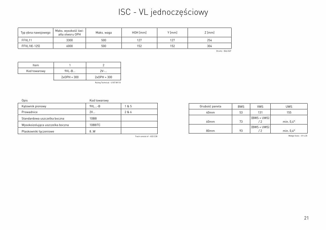
21
Opis Kod towarowy
Kątownik pionowy 9VL…-B 1 & 5
Prowadnice 2V… 2 & 6
Standardowa uszczelka boczna 1088I
Wysokoizolująca uszczelka boczna 1088ITC
Płaskowniki łączeniowe 8..WTrack consist of - A32:C38
Typ ębna nawojowego Maks. wysokość świ-atła otworu OPH Maks. waga HOH [mm] Y [mm] Z [mm]
FFVL11 3300 500 127 127 254
FFVL18(-125) 6000 500 152 152 304Drums - B46:G49
Item 1 2
Kod towarowy 9VL-B… 2V-…
2xOPH + 300 2xOPH + 300
Ruling Technical - U107:W110
Grubość panela BWS VWS UWS
40mm 53 131 155
60mm 73(BWS + UWS)
/ 2 min. 0,4°
80mm 93(BWS + UWS)
/ 2 min. 0,4°Wedge Sizes - I31:L35
ISC - VL jednoczęściowy
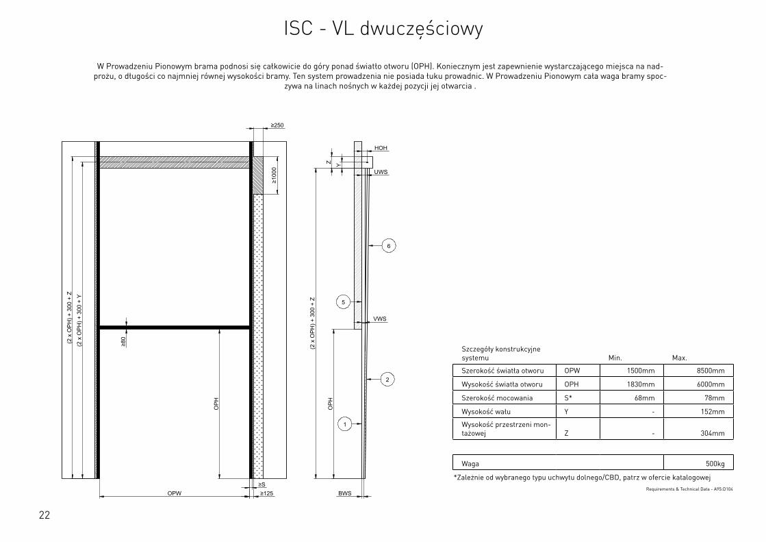
22
Szczegóły konstrukcyjne systemu Min. Max.
Szerokość światła otworu OPW 1500mm 8500mm
Wysokość światła otworu OPH 1830mm 6000mm
Szerokość mocowania S* 68mm 78mm
Wysokość wału Y - 152mm
Wysokość przestrzeni mon-tażowej Z - 304mm
Waga 500kg
*Zależnie od wybranego typu uchwytu dolnego/CBD, patrz w ofercie katalogowejRequirements & Technical Data - A95:D104
OPH
HOH
Y
BWS
Z
OPH
OPW ≥S ≥125
≥80
≥250
≥10
00
UWS
VWS (2
x O
PH) +
300
+ Z
(2 x
OPH
) + 3
00 +
Y
(2 x
OPH
) + 3
00 +
Z
2
1
6
5
This
wor
k is
cop
yrig
ht a
nd n
o pa
rt m
ay b
e re
prod
uced
, by
any
proc
ess,
nor
may
any
oth
er e
xclu
sive
righ
t be
exer
cise
d w
ithou
t the
per
mis
sion
of A
SSA
ABLO
Y.
Surface treatment:
V9_2
019_
02_2
1_dr
wRev.:Document ID
Material: General tolerance:
Volume: Mass: Surface area: Created (YYYY-MM-DD): Designed by: Drawn by: Scale: Projection:
Alternate ID552648112.93 mm³ 1:100 (A3)95351980.55 mm²552648.11 gram
ISO 8015ISO 2768-mH
1SHEET 1 OF 1Configuration:ISC-VL-2Piece
W Prowadzeniu Pionowym brama podnosi się całkowicie do góry ponad światło otworu (OPH). Koniecznym jest zapewnienie wystarczającego miejsca na nad-prożu, o długości co najmniej równej wysokości bramy. Ten system prowadzenia nie posiada łuku prowadnic. W Prowadzeniu Pionowym cała waga bramy spoc-
zywa na linach nośnych w każdej pozycji jej otwarcia .
ISC - VL dwuczęściowy
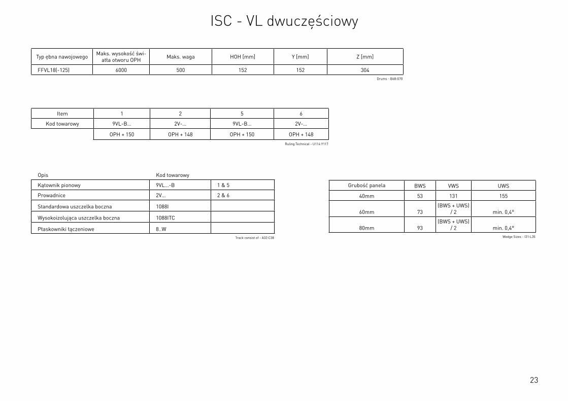
23
Opis Kod towarowy
Kątownik pionowy 9VL…-B 1 & 5
Prowadnice 2V… 2 & 6
Standardowa uszczelka boczna 1088I
Wysokoizolująca uszczelka boczna 1088ITC
Płaskowniki łączeniowe 8..WTrack consist of - A32:C38
Typ ębna nawojowego Maks. wysokość świ-atła otworu OPH Maks. waga HOH [mm] Y [mm] Z [mm]
FFVL18(-125) 6000 500 152 152 304Drums - B68:G70
Item 1 2 5 6
Kod towarowy 9VL-B… 2V-… 9VL-B… 2V-…
OPH + 150 OPH + 148 OPH + 150 OPH + 148
Ruling Technical - U114:Y117
Grubość panela BWS VWS UWS
40mm 53 131 155
60mm 73(BWS + UWS)
/ 2 min. 0,4°
80mm 93(BWS + UWS)
/ 2 min. 0,4°Wedge Sizes - I31:L35
ISC - VL dwuczęściowy
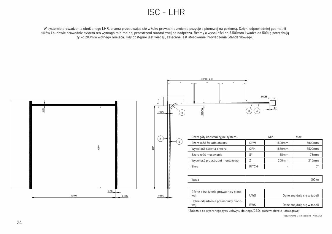
24
Szczegóły konstrukcyjne systemu Min. Max.
Szerokość światła otworu OPW 1500mm 5000mm
Wysokość światła otworu OPH 1830mm 5500mm
Szerokość mocowania S* 68mm 78mm
Wysokość przestrzeni montażowej Z 200mm 215mm
Skos PITCH - 0°
Waga 400kg
Górne odsadzenie prowadnicy piono-wej UWS Dane znajdują się w tabeli
Dolne odsadzenie prowadnicy piono-wej BWS Dane znajdują się w tabeli
*Zależnie od wybranego typu uchwytu dolnego/CBD, patrz w ofercie katalogowejRequirements & Technical Data - A108:D120
OPH
UWS
BWS
PIT
CH
OPW
OPH
≥80
≥80
≥125
HOH
47
= = = OPH - 210
Z
12
3 48
This
wor
k is
cop
yrig
ht a
nd n
o pa
rt m
ay b
e re
prod
uced
, by
any
proc
ess,
nor
may
any
oth
er e
xclu
sive
righ
t be
exer
cise
d w
ithou
t the
per
mis
sion
of A
SSA
ABLO
Y.
Surface treatment:
V9_2
019_
02_2
1_dr
wRev.:Document ID
Material: General tolerance:
Volume: Mass: Surface area: Created (YYYY-MM-DD): Designed by: Drawn by: Scale: Projection:
Alternate ID142976550.27 mm³ 1:100 (A3)25577248.67 mm²142976.55 gram
ISO 8015ISO 2768-mH
1SHEET 1 OF 1Configuration:ISC-LHR
W systemie prowadzenia obniżonego LHR, brama przesuwając się w łuku prowadnic zmienia pozycję z pionowej na poziomą. Dzięki odpowiedniej geometrii łuków i budowie prowadnic system ten wymaga minimalnej przestrzeni montażowej na nadprożu. Bramy o wysokości do 5.500mm i wadze do 500kg potrzebują
tylko 200mm wolnego miejsca. Gdy dostępne jest więcej , zalecane jest stosowanie Prowadzenia Standardowego.
ISC - LHR
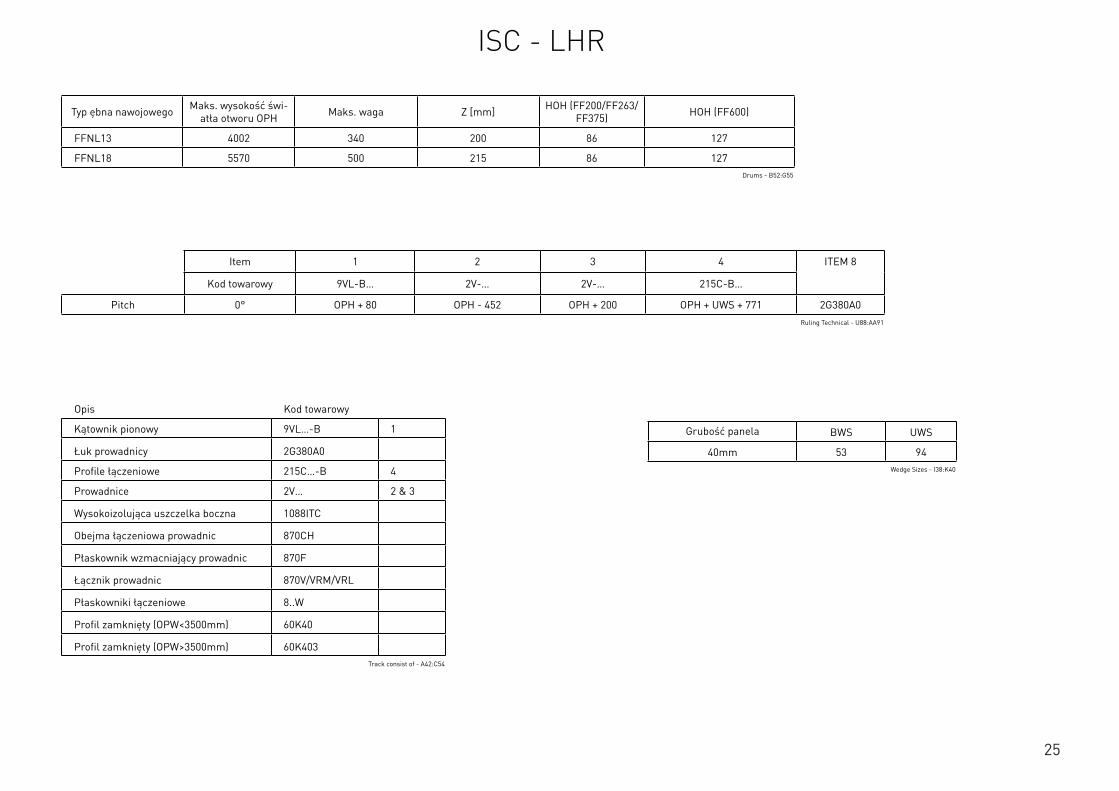
25
Szczegóły konstrukcyjne systemu Min. Max.
Szerokość światła otworu OPW 1500mm 5000mm
Wysokość światła otworu OPH 1830mm 5500mm
Szerokość mocowania S* 68mm 78mm
Wysokość przestrzeni montażowej Z 200mm 215mm
Skos PITCH - 0°
Waga 400kg
Górne odsadzenie prowadnicy piono-wej UWS Dane znajdują się w tabeli
Dolne odsadzenie prowadnicy piono-wej BWS Dane znajdują się w tabeli
*Zależnie od wybranego typu uchwytu dolnego/CBD, patrz w ofercie katalogowejRequirements & Technical Data - A108:D120
Typ ębna nawojowego Maks. wysokość świ-atła otworu OPH Maks. waga Z [mm] HOH (FF200/FF263/
FF375) HOH (FF600)
FFNL13 4002 340 200 86 127
FFNL18 5570 500 215 86 127Drums - B52:G55
Item 1 2 3 4 ITEM 8
Kod towarowy 9VL-B… 2V-… 2V-… 215C-B…
Pitch 0° OPH + 80 OPH - 452 OPH + 200 OPH + UWS + 771 2G380A0Ruling Technical - U88:AA91
Grubość panela BWS UWS
40mm 53 94Wedge Sizes - I38:K40
Opis Kod towarowy
Kątownik pionowy 9VL…-B 1
Łuk prowadnicy 2G380A0
Profile łączeniowe 215C…-B 4
Prowadnice 2V… 2 & 3
Wysokoizolująca uszczelka boczna 1088ITC
Obejma łączeniowa prowadnic 870CH
Płaskownik wzmacniający prowadnic 870F
Łącznik prowadnic 870V/VRM/VRL
Płaskowniki łączeniowe 8..W
Profil zamknięty (OPW<3500mm) 60K40
Profil zamknięty (OPW>3500mm) 60K403Track consist of - A42:C54
ISC - LHR
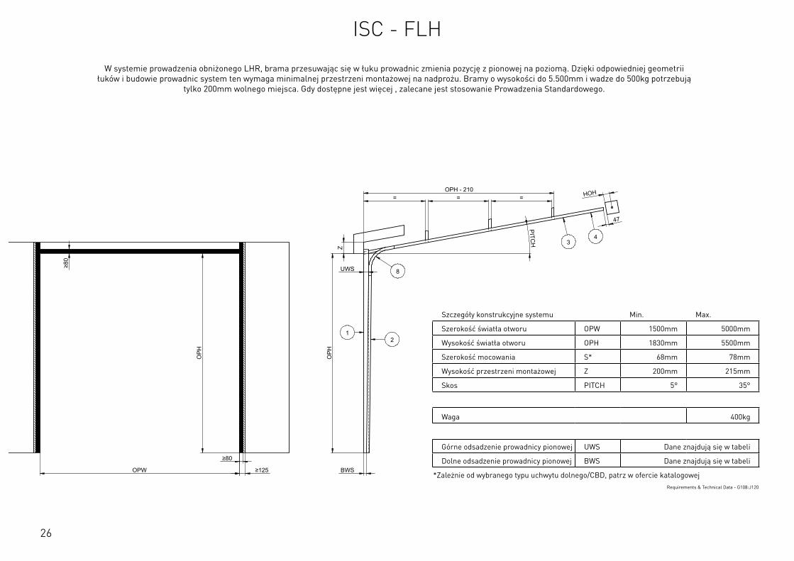
26
Szczegóły konstrukcyjne systemu Min. Max.
Szerokość światła otworu OPW 1500mm 5000mm
Wysokość światła otworu OPH 1830mm 5500mm
Szerokość mocowania S* 68mm 78mm
Wysokość przestrzeni montażowej Z 200mm 215mm
Skos PITCH 5° 35°
Waga 400kg
Górne odsadzenie prowadnicy pionowej UWS Dane znajdują się w tabeli
Dolne odsadzenie prowadnicy pionowej BWS Dane znajdują się w tabeli
*Zależnie od wybranego typu uchwytu dolnego/CBD, patrz w ofercie katalogowejRequirements & Technical Data - G108:J120
OPH
UWS
BWS
PITCH
OPW
OPH
≥80
≥80
≥125
HOH
47
= = = OPH - 210
Z
12
34
8
This
wor
k is
cop
yrig
ht a
nd n
o pa
rt m
ay b
e re
prod
uced
, by
any
proc
ess,
nor
may
any
oth
er e
xclu
sive
righ
t be
exer
cise
d w
ithou
t the
per
mis
sion
of A
SSA
ABLO
Y.
Surface treatment:
V9_2
019_
02_2
1_dr
wRev.:Document ID
Material: General tolerance:
Volume: Mass: Surface area: Created (YYYY-MM-DD): Designed by: Drawn by: Scale: Projection:
Alternate ID142758386.18 mm³ 1:100 (A3)25601845.72 mm²142758.39 gram
ISO 8015ISO 2768-mH
1SHEET 1 OF 1Configuration:ISC-FHR
W systemie prowadzenia obniżonego LHR, brama przesuwając się w łuku prowadnic zmienia pozycję z pionowej na poziomą. Dzięki odpowiedniej geometrii łuków i budowie prowadnic system ten wymaga minimalnej przestrzeni montażowej na nadprożu. Bramy o wysokości do 5.500mm i wadze do 500kg potrzebują
tylko 200mm wolnego miejsca. Gdy dostępne jest więcej , zalecane jest stosowanie Prowadzenia Standardowego.
ISC - FLH
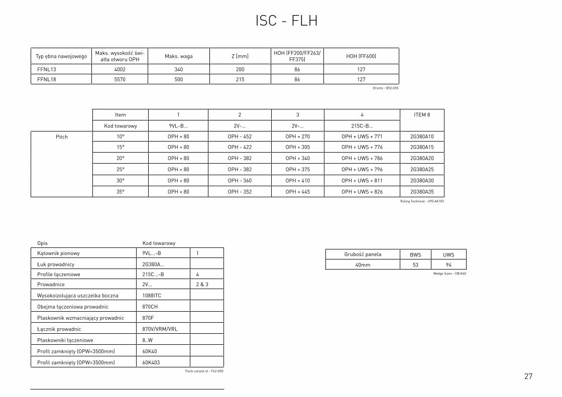
27
Typ ębna nawojowego Maks. wysokość świ-atła otworu OPH Maks. waga Z [mm] HOH (FF200/FF263/
FF375) HOH (FF600)
FFNL13 4002 340 200 86 127
FFNL18 5570 500 215 86 127Drums - B52:G55
Item 1 2 3 4 ITEM 8
Kod towarowy 9VL-B… 2V-… 2V-… 215C-B…
Pitch 10° OPH + 80 OPH - 452 OPH + 270 OPH + UWS + 771 2G380A10
15° OPH + 80 OPH - 422 OPH + 305 OPH + UWS + 776 2G380A15
20° OPH + 80 OPH - 382 OPH + 340 OPH + UWS + 786 2G380A20
25° OPH + 80 OPH - 382 OPH + 375 OPH + UWS + 796 2G380A25
30° OPH + 80 OPH - 360 OPH + 410 OPH + UWS + 811 2G380A30
35° OPH + 80 OPH - 352 OPH + 445 OPH + UWS + 826 2G380A35
Ruling Technical - U95:AA103
Grubość panela BWS UWS
40mm 53 94Wedge Sizes - I38:K40
Opis Kod towarowy
Kątownik pionowy 9VL…-B 1
Łuk prowadnicy 2G380A…
Profile łączeniowe 215C…-B 4
Prowadnice 2V… 2 & 3
Wysokoizolująca uszczelka boczna 1088ITC
Obejma łączeniowa prowadnic 870CH
Płaskownik wzmacniający prowadnic 870F
Łącznik prowadnic 870V/VRM/VRL
Płaskowniki łączeniowe 8..W
Profil zamknięty (OPW<3500mm) 60K40
Profil zamknięty (OPW>3500mm) 60K403Track consist of - F42:H55
ISC - FLH

28
INFORMACJE DOTYCZĄCE UCHWYTU DOLNEGO
NL / HL / VL LHR
Uszczelka boczna Uszczelka boczna
1088I / 1088ITC 1088ITC
Kod towarowy S [mm] S [mm]Dodane aby uzyskać 5mm luzu
pomiędzy prowadnicą i uchwytem*
425HD 76 - 2066-10
427SX 68 78 2066-07
428TAI 72 78 -
429 68 78 2066-05
429S 68 78 2066-10
440-REGL 76 78 -
440HD 76 - -
440-600 74 78 -
440S 74 78 -
440 74 78 -
444 78 - -
*Luz 5mm jest niezbędny aby możliwy był ruch ±5mm
Bottom Brackets - A3:D19
E E
F F
SCALE: GENERALROUGHNESS:
PROJECTION:FORMAT: UNIT:
mmTOLERANCES UNLESS
OTHERWISE STATED Acc. To ISO 2768-cK
MATERIAL
TREATMENT
DESCRIPTION
ARTICLE CODE DRAWING NUMBER REVISION
CREATION DATE NETTO WEIGHTCREATED BY
THICKNESS
FLAT WIDTH
FLAT LENGHT
mm
mm
mm
This drawing is property ofFlexiForce
and contains confidentionalinformation.
All rights are strictly reserved.Reproduction
and use for production purposesissue to
third parties in any form whatsoever,is not permitted without written authority from the proprietors.
36 001 001 A
Position of Vertical Angle based on Side Seal and Bottom Bracket
...
JiGa 9-8-2016 538,183 kg
-
A3-
-
---
-C:\V
aultWor
kspa
ce\R
&D\T
eke n
inge
n\36
\360
0100
1\36
001 0
01\4
40 -
108
8I.ia
m
0.5-3 >3-6 >6-30 >30-120 >120-400 >400-1000 >1000-2000 >2000-4000
:
:
:
: :
: : :
: : :
±0.20 ±0.30 ±0.50 ±0.80 ±1.20 ±2.00 ±3.00 ±4.00
Nomi
nal dime
nsion
:
3
A3 Changed values in table, see excel file JiGa 20-01-2017A2 Changed values in table, see excel file JiGa 10-01-2017REV. DESCRIPTION NAME DATE
Side Seal Side Seal 1088I / 1088IT
Bottom Bracket S [mm]Technical S [mm]CommercialAdd to achieve play of 5mm between track and bracket
425HD 75,5 76 2066-10427SX 67,5 68 2066-07428TAI 72 72 -429 67,5 68 2066-05429S 67,5 68 2066-10440-REGL 75,5 76 -440HD 75,5 76 -440-600 73,5 74 -440S 73,5 74 -440 73,5 74 -444 77,5 78 -
S
22,5
1088I
22,5
S
1088ITAcceptable
The play of 5mm is needed for the required pendel of +5mm/-5mm
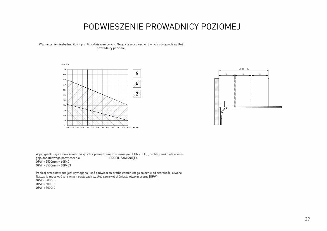
29
PODWIESZENIE PROWADNICY POZIOMEJ
Wyznaczenie niezbędnej ilości profili podwieszeniowych. Nelęży je mocować w równych odstępach wzdłuż prowadnicy poziomej
W przypadku systemów konstrukcyjnych z prowadzeniem obniżonym ( LHR i FLH) , profile zamknięte wyma-gają dodatkowego podwieszenia. PROFIL ZAMKNIĘTY: OPW < 3500mm = 60K40 OPW > 3500mm = 60K403 Poniżej przedstawiona jest wymagana ilość podwieszeń profila zamkniętego zależnie od szerokości otworu. Należy je mocować w równych odstępach wzdłuż szerokości światła otworu bramy (OPW). OPW < 3000: 0 OPW < 5000: 1 OPW < 7000: 2
OPH
BWS
OPH
OPW
≥S
≥125
≥10
00
≥80
*
HL
+ Y
HL
+ Z
OPH - HL
= = = ≥250
12
This
wor
k is
cop
yrig
ht a
nd n
o pa
rt m
ay b
e re
prod
uced
, by
any
proc
ess,
nor
may
any
oth
er e
xclu
sive
righ
t be
exer
cise
d w
ithou
t the
per
mis
sion
of A
SSA
ABLO
Y.
Surface treatment:
V9_2
019_
02_2
1_dr
wRev.:Document ID
Material: General tolerance:
Volume: Mass: Surface area: Created (YYYY-MM-DD): Designed by: Drawn by: Scale: Projection:
Alternate ID415397163.98 mm³ 1:100 (A3)74737484.21 mm²415397.16 gram
ISO 8015ISO 2768-mH
1SHEET 1 OF 1Configuration:ISC-HL-1Piece
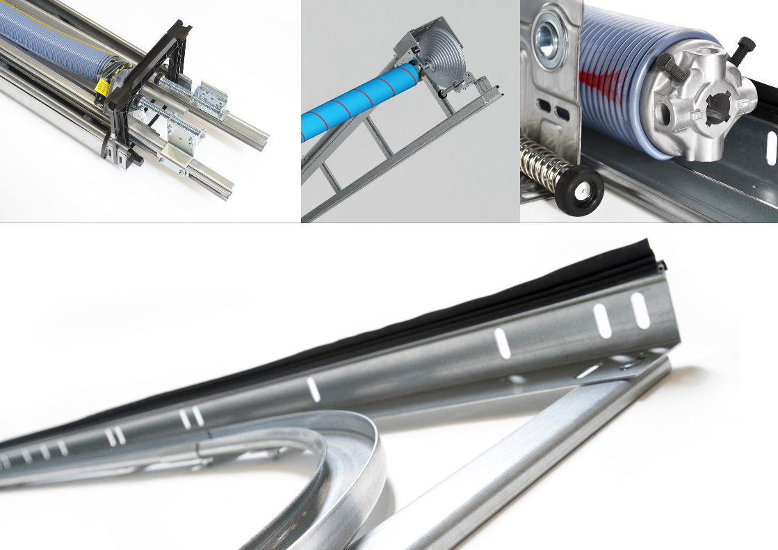
30

31
MIEJSCA GDZIE MOŻNA NAS ZNALEŹĆ
FlexiForce B.V. Hanzeweg 19 3771 NG Barneveld PO Box 37 3770 AA Barneveld Pays-Bas +31-(0)342-427777 [email protected]
FlexiForce Hungary Kft. Medvefű str. 24 4031 Debrecen Hongrie +36-52561260 [email protected]
FlexiForce Ibérica, S.L. ApartadoCorreos 403 Ctra. Nacional 332, Km. 211 46780 – Oliva (Valence) Espagne +34 96.285.82.50 [email protected]
FlexiForce Poland Sp. z o.o. Norblina 17/19 95-015 Głowno Pologne +48 426500491 [email protected]
FlexiForce Italia Srl. Via deiTigli CNM 25020 Alfianello Italie +39 0309936510 [email protected]
FlexiForce Turkey Marmara Geri Donusumculer- TopluİsyeriYapıKooperatifi SekerpinarMahallesi AycicekSokakKapi No: 24 (245 ada, 31 parsel) 41420, Çayirova, KOCAELI / TURQUIE +90 262 658 2058 [email protected]
www.flexiforce.com
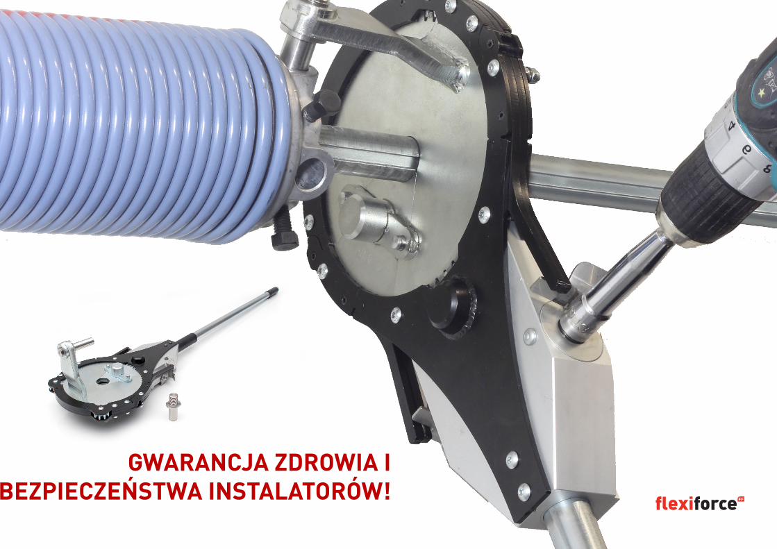
32
GWARANCJA ZDROWIA I BEZPIECZEŃSTWA INSTALATORÓW!

![BWS Newsletter no 12 - British Wittgenstein Society · 2015. 10. 13. · From: British Wittgenstein Society [bws@herts.ac.uk ] Subject: Newsletter no.12 Sponsored by Shell BWS website](https://img.pdfslide.us/doc/110x75/600e5a9f5606de1b613d0610/bws-newsletter-no-12-british-wittgenstein-society-2015-10-13-from-british.jpg)