Embed Size (px)
Citation preview
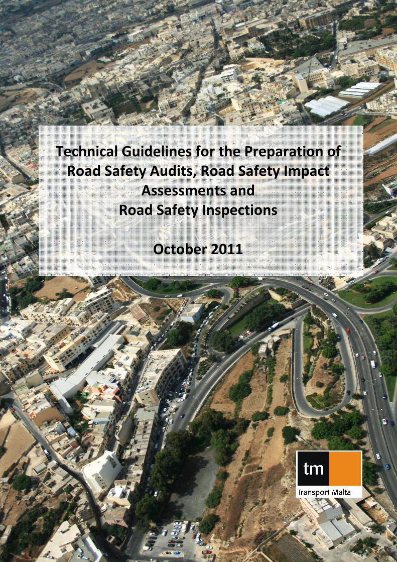
Technical Guidelines for the Preparation of
Road Safety Audits, Road Safety Impact
Assessments and
Road Safety Inspections
October 2011


Technical Guidelines for the Preparation of
Road Safety Audits, Road Safety Impact
Assessments and
Road Safety Inspections
October 2011
Cover photo credit: Peter Paul Barbara
1 October 2011 Version 1.3


Transport Malta October 2011
Technical Guidelines for the Preparation of Road Safety Audits,
Road Safety Impact Assessments and Road Safety Inspections
Contents
Foreword ................................................................................................................................... 1
1. Road Safety Impact Assessment for Infrastructural Projects....................................... 3
1.1 Impact Assessment Team ........................................................................................... 4
1.2 Impact Assessment Team Training, Skills and Experience .......................................... 4
1.3 Impact Assessment Brief............................................................................................. 5
1.4 Elements of a Road Safety Impact Assessment .......................................................... 5
1.4.1 Problem Definition ........................................................................................ 5
1.4.2 Current Situation and future ‘DO SOMETHING’ Scenario ............................. 6
1.5 Road Safety Objectives ............................................................................................... 8
1.6 Analysis of impacts on road safety of the proposed alternatives............................... 8
1.7 Comparison of Alternatives including Cost-Benefit Analysis .................................... 10
1.8 Presentation of the Range of Possible Solutions ...................................................... 11
2. Road Safety Audits for Infrastructural Projects.......................................................... 13
2.1 Stages of a Safety Audit ............................................................................................ 14
2.2 Audit Shelf Life .......................................................................................................... 15
2.3 Audit Team................................................................................................................ 15
2.4 Audit Team Training, Skills and Experience .............................................................. 15
2.5 Audit Brief ................................................................................................................. 16
2.6 Structure and Content of the Road Safety Audit Report .......................................... 16
2.7 Safety Audit Draft Design Stage 1 ............................................................................ 18
2.7.1 Audit Items to be checked........................................................................... 18
2.8 Safety Audit Detailed Design Stage 2........................................................................ 20
2.8.1 Information Required for the Audit ............................................................ 20
2.8.2 Audit Items to be checked........................................................................... 20
2.9 Road Safety Audit during Pre-Opening Stage 3 ........................................................ 26
2.9.1 Audit Items to be checked........................................................................... 26
2.10 Road Safety Audit Early Operation Stage 4 (Optional) ............................................. 29
2.10.1 Audit Items to be checked........................................................................... 29
2.11 Exception Report....................................................................................................... 33
3. Ranking of High Accident Concentration Sections and Network Safety Ranking ...... 35
3.1 Identification of Road Sections with a High Accident Concentration ....................... 36
3.2 Analysis of Accident BlackSpots ................................................................................ 37
3.3 Accident Types .......................................................................................................... 38
3.4 Collision Investigation ............................................................................................... 39
3.5 Detailed Accident Analysis ........................................................................................ 41
3.6 Parameters for Safety Evaluation ............................................................................. 41
Transport Malta October 2011
Technical Guidelines for the Preparation of Road Safety Audits,
Road Safety Impact Assessments and Road Safety Inspections
3.7 Design and Implementation of Remedial Measures................................................. 42
3.8 Traffic Calming .......................................................................................................... 43
4. Road Safety Inspections ............................................................................................. 45
4.1 STEP 1: Scheduling of inspections............................................................................. 46
4.2 STEP 2: Preparation for the Inspection Visit ............................................................. 46
4.3 STEP 3: Road Safety Inspection Visit ......................................................................... 46
4.4 STEP 4: Communication of Observations.................................................................. 47
4.5 STEP 5: Examination of the Inspection Report.......................................................... 48
4.6 STEP 6: Report of the Overseeing Authority ............................................................. 48
4.7 Monitoring and Evaluation ....................................................................................... 48
Annex 1: First Year Rate of Return (FYRR)............................................................................... 51
Annex 2: Example of an Exception Report .............................................................................. 52
Annex 3: Road Accidents Typology Catalogue ........................................................................ 59
Annex 4: Signs and Symbols Used In Collision Diagrams ........................................................ 60
Annex 5: Vehicle Movement Codes Used In New Zealand ..................................................... 61
Annex 6: Possible Links among Accidents Types, Cause Of Accident and Lead Deficiency .... 62
Annex 7: Comparative Testing................................................................................................. 66
Annex 8: Toolbox for Road Safety Interventions..................................................................... 74
Annex 9: Toolbox for Speed Control Measures....................................................................... 82
Annex 10: Checklist for Road Safety Inspections .................................................................... 92
References............................................................................................................................. 111

Transport Malta October 2011
Technical Guidelines for the Preparation of Road Safety Audits,
Road Safety Impact Assessments and Road Safety Inspections
List of Tables
Table 1 : Possible Accident Reduction in Relation to Specific Interventions ............................ 8 Table 2 : Cost per Accident by Road Type and Severity .......................................................... 11 Table 3 : The Weighting used for the Ranking of Accident Locations..................................... 37 Table 4 : Comparative Testing - Poisson Test.......................................................................... 66 Table 5 : CHi-Square (x
2) Test Example.................................................................................... 73
Table 6 : Pedestrian Crossing Characteristics.......................................................................... 75 Table 7 : Recommended Widths for Cycle Routes .................................................................. 78 Table 8 : Spacing of Yellow Bar Markings on the road ............................................................ 85 Table 9 : Checklist for Road Safety Inspection ........................................................................ 92
List of Figures
Figure 1 : Road Accidents Typology Catalogue........................................................................ 59 Figure 2 : Signs and Symbols in Collision Diagrams................................................................. 60 Figure 3 : Vehicle Movement Codes used in New Zealand ..................................................... 61 Figure 4 : Poisson Probabilities - Single Factor Values ............................................................ 67 Figure 5 : Poisson Probabilities - Cumulative Factor Values ................................................... 70 Figure 6 : The CHi2 Distribution............................................................................................... 73 Figure 7 : Raised Zebra Crossing.............................................................................................. 76 Figure 8 : Road Markings / Approach to School ...................................................................... 76 Figure 9 : Pedestrian U-Bar...................................................................................................... 77 Figure 10 : Pedestrian Railing .................................................................................................. 77 Figure 11 : Pedestrian Footways Emblem ............................................................................... 77 Figure 12 : Typical Signage Layout for Cycle Routes ............................................................... 79 Figure 13 : One – Way or Restricted Access Sign .................................................................... 80 Figure 14 : Rumble Strips......................................................................................................... 81 Figure 15 : Speed Limit Signage............................................................................................... 83 Figure 16 : Speed Limit Road Markings ................................................................................... 83 Figure 17 : Dragon's Teeth Road Markings.............................................................................. 84 Figure 18 : Yellow Bar Markings .............................................................................................. 85 Figure 19 : Specifications for Round-Topped Road Hump ...................................................... 86 Figure 20 : Line Markings and Signage for Round-Topped Road Hump................................. 86 Figure 21 : Build Outs .............................................................................................................. 87 Figure 22 : Chicanes................................................................................................................. 88 Figure 23 : Speed Cushions...................................................................................................... 89 Figure 24 : Lane Narrowing - Hatching.................................................................................... 90 Figure 25 : Lane Narrowing - Pinch Point ................................................................................ 90 Figure 26 : Gateway including Hatching, Anti-Skid Material, Speed Limit and Central Island 91 Figure 27 : Gateway including Hatching, Dragons' Teeth, Speed Limit,.................................. 91 Figure 28 : Gateway including Road Narrowing, ..................................................................... 91

Transport Malta October 2011
Technical Guidelines for the Preparation of Road Safety Audits,
Road Safety Impact Assessments and Road Safety Inspections
Transport Malta 1 October 2011
Technical Guidelines for the Preparation of Road Safety Audits,
Road Safety Impact Assessments and Road Safety Inspections
Foreword
In the White Paper on European Transport Policy for 2010 and in its Communication
on a European Road Safety Action Programme of June 2003, the European
Commission announced that it would take the initiative on road infrastructure safety
and subsequently the European Parliament invited the Commission to provide
guidelines for high-risk spot management and road safety audits.
Directive 2008/96/EC of the European Parliament and of the Council of 19 November
2008 on Road Infrastructure Safety Management has the objective to ensure that
safety is integrated in all phases of planning, design and operation of road
infrastructure in the Trans-European Road Network (TEN-T).
The Directive requires all Member States to undertake Road Safety Audits, Road
Safety Impact Assessments, Road Safety Inspections and high frequency Collision
Investigations on the TEN-T roads.
The directive sets out four areas of analysis in relation to existing roads and new
roads. Network Safety Ranking and Road Safety Inspections are targeted at the
existing TEN-T road network whilst Road Safety Impact Assessments and Road Safety
Audits are targeted at new TEN-T roads.
The Directive also requires that Member States to ensure a training curriculum for
road safety auditors. Transport Malta has worked with TMS Consultancy to develop
this syllabus. Member States are also to ensure that road safety auditors undergo
initial training resulting in an award of a Certificate of Competence followed by
periodic training courses.
The date identified by the Directive for the transposition of the directive into
national law was 19th
December 2010. This was transposed and now is part of S.L.
499.57 New Roads and Road Works Regulations since Training Curricula and Auditing
Guidelines were required to be in place by 19th
December 2011. Safety Audits need
to be undertaken by qualified auditors by 19th
December 2013.
Integrated Transport Strategy Directorate
Transport Malta
October 2011

Transport Malta 2 October 2011
Technical Guidelines for the Preparation of Road Safety Audits,
Road Safety Impact Assessments and Road Safety Inspections

Transport Malta 3 October 2011
Technical Guidelines for the Preparation of Road Safety Audits,
Road Safety Impact Assessments and Road Safety Inspections
1. Road Safety Impact Assessment for Infrastructural Projects
Directive 2008/96/EC and S.L. 499.57 define a Road Safety Impact Assessment as a
strategic comparative analysis of the impact of a new road or a substantial
modification to the existing network on the safety performance of the road network.
Road Safety Impact Assessment is to be carried out at the initial planning stage and
the results are to be considered during the planning process. Where changes are
required, the impact assessment shall indicate the road safety considerations which
contribute to the specific remedial intervention and provide for the analysis of
different alternative through a cost-benefit analysis.
It is important to be able to ascertain the impact of road safety which results from
the construction of new roads or when carrying out substantial modifications to the
existing road network. Such also applies to other schemes or developments which
have a considerable impact on the traffic patterns. (Wegman et al., 1994)
The scenario method is used to undertake a Safety Impact Assessment. The first part
is to analyse the base line which is the existing road network, the existing traffic
patterns and the accident data. (Wegman et al., 1994) The road network is to be
perceived as being made up of different types of roads with different characteristics
and with junctions and links between junctions. For every section, there are specific
traffic volumes and accident data. Alternative scenario s to this existing situation are
the changes to be studied in the impact assessment in relation to the physical
infrastructure and the resulting traffic volumes in the future. (Wegman et al., 1994)
The second part is to interpret these changes in relation to their impacts on the
number of accidents and injuries. (Wegman et al., 1994) Such is carried out through
the analysis of quantitative indicators of risk, taken as being injury accident rates per
million vehicle km for each type of road. (European Transport Safety Council, 1997)
The third part is to establish the cost-effectiveness of the schemes as part of the
road safety impact assessments. Such may sometimes be difficult to quantify
accurately. The costs of the projects or works being undertaken on the road network
might not be too difficult to quantify however the benefits require an estimate to be
made of the difference in accident costs occurring on the proposed schemes
compared with the existing scenario and other possible alternative schemes.
(European Transport Safety Council, 1997)
If the entity or person overseeing a project considers it unnecessary for a Road
Safety Impact Assessment to be applied to a specific Road Upgrading or Re-Design
scheme, approval must be obtained from the Integrated Transport Strategy
Directorate (ITSD) of Transport Malta (TM). The request for this exemption must be
supported by clear reasons why the impact assessment is not necessary. An
exemption will only be approved when in the opinion of ITSD the effect of the
proposed works on the existing road network would be minimal.

Transport Malta 4 October 2011
Technical Guidelines for the Preparation of Road Safety Audits,
Road Safety Impact Assessments and Road Safety Inspections
The scope of the Road Safety Impact Assessment does not include health and safety
legislation in relation to the construction, maintenance and use of such road.
The Road Safety Impact Assessment considers only road safety matters and it is not a
check of the design standards and nor does it consider structural safety.
1.1 Impact Assessment Team
The Impact Assessment Team needs to be independent of the Design Team but may
be or form part of the Audit Team.
Impact Assessment Team needs to have the necessary training, skills and experience
to be accepted for carrying out a Safety Audit.
The Road Safety Impact Assessment Team shall consist of one Impact Assessment
Team Leader and at least one Impact Assessment Team member to enable
discussion of problems and recommendations and to maximize the potential to
identify problems. A maximum of two Impact Assessment Team Observers may join
the team to gain experience in carrying out Road Safety Impact Assessments.
1.2 Impact Assessment Team Training, Skills and Experience
The Impact Assessment Team leader requires to have a minimum of four years
Accident Investigation or Road Safety Engineering Experience, would have attended
at least 10 days of formal Accident Investigation or Road Safety Engineering Training
and demonstrate a minimum of two days of Continuous Personal Development in
the field of Accident Investigation or Road safety Engineering in the past twenty-four
months.
The Impact Assessment Team Member requires to have a minimum of two years
Accident Investigation or Road Safety Engineering Experience, would have attended
at least 10 days of formal Accident Investigation or Road Safety Engineering Training
and demonstrate a minimum of two days of Continuous Personal Development in
the field of Accident Investigation or Road safety Engineering in the past twenty-four
months.
The Impact Assessment Team Observer requires to have a minimum of one year
Accident Investigation or Road Safety Engineering Experience, would have attended
at least 10 days of formal Accident Investigation or Road Safety Engineering Training.
The Impact Assessment Team might need to consider the appointment of Special
Advisors in the case of complex signal controlled junctions, road design, traffic
management or maintenance works. The Advisor would not be a member of the
Impact Assessment team but would advise the team on matters related to his/her
specialization.

Transport Malta 5 October 2011
Technical Guidelines for the Preparation of Road Safety Audits,
Road Safety Impact Assessments and Road Safety Inspections
1.3 Impact Assessment Brief
The Design Team is responsible for the preparation of an Impact Assessment Brief.
The Safety Impact Assessment Brief is to include all the information necessary for
enable an efficient and effective Road Safety Impact Assessment to be carried out.
The Impact Assessment brief should include the:
• All drawings of the proposed scheme showing the full geographical extent of
the scheme and any adjacent areas
• Details of any departures and relaxation from design standards
• General scheme details including the purpose of the scheme, speed limits,
traffic flows, forecasted flows, queue lengths, non-motorised user flows and
desire lines and details of any environmental constraints.
• Any special factors which may affect road safety such as the location of
schools, emergency access points.
• The previous 36-month accident data in the form of stick diagrams and
interpreted listings. The accident data should be for the extent of the
scheme and for adjacent roads.
If the Impact Assessment Team considers that the Impact Assessment brief does not
contain all the information required for the purpose then requests for further
information are to be submitted to the Design Team. Any information requested but
not provided by the Design Team should be identified in the Impact Assessment
Report.
1.4 Elements of a Road Safety Impact Assessment
1.4.1 Problem Definition
A full description is to be provided of what is aimed for with the proposed activity,
the activity itself and the manner in which it will be carried out as well as a
description of the alternatives to this activity which should reasonably betaken into
consideration. (Wegman et al. 1994) The alternatives to be described should
include those which enable realization of the best options available for the
improvement of road safety. (Wegman et al. 1994) This is to describe which
problem areas, developments and prognoses have led to the proposed activity,
hence the infrastructural changes, and which problems will be solved. (Wegman et
al. 1994)
The extent of the assessment depends on the scale of the proposed schemes:
- small-scale schemes where the impact of change can usually be expected to be
confined largely within the scheme itself
- for larger schemes, the impact on accident occurrence can be expected to be
felt over a larger part of the road network. (European Transport Safety Council,
1997)

Transport Malta 6 October 2011
Technical Guidelines for the Preparation of Road Safety Audits,
Road Safety Impact Assessments and Road Safety Inspections
and is defined by considering different road types, the corresponding values of
relevant safety indicators and the forecast traffic volumes, the impact on accident
occurrence can be estimated for different alternatives. (European Transport Safety
Council, 1997)
1.4.2 Current Situation and future ‘DO SOMETHING’ Scenario
STEP 1: Categorising a road network
(Wegman et al. 1994)
The following road characteristics are to be defined:
• Number of carriageways
• Number of lanes per carriageway
• Number of directions per carriageway
• Existence of parallel facilities
• Type of road users
• Vehicle type classification
The road type is to be defined based on the above criteria for road types outside
urban areas:
• Arterial/distributor roads with three or more lanes per carriageway
• Arterial/distributor roads with two or more lanes per carriageway
• Arterial/distributor roads with dual carriageway
• Arterial/distributor roads with one carriageway
• All purpose road with dual carriageway
• All purpose road with one carriageway
• All purpose road with one carriageway, two lanes
• All purpose road with one carriageway, one lane
The road type is to be defined based on the above criteria for road types inside
urban areas:
• Dual carriageway, two directions, two parallel facilities
• Dual carriageway, two directions, one parallel facility
• Dual carriageway, two directions, no parallel facilities
• One carriageway, two directions, two parallel facilities
• One carriageway, two directions, one parallel facilities
• One carriageway, two directions, no parallel facility
• One carriageway, one direction, two parallel facilities
• One carriageway, one direction, one parallel facility
• One carriageway, one direction, no parallel facilities
STEP 2: Road Safety Indicators per Type of Road
(Wegman et al. 1994)

Transport Malta 7 October 2011
Technical Guidelines for the Preparation of Road Safety Audits,
Road Safety Impact Assessments and Road Safety Inspections
Per type of road the following variables have to be measured to estimate the road
safety indicators:
• Road length
• Number of injury accidents
• Number of casualties
• Number of fatalities
The recommended road safety indicators to be used are:
• Number of injury accidents per kilometer per year per road type
• Number of casualties per injury accident
• Number of fatalities per 100 casualties.
STEP 3: Development of Road Safety Indicators
1.28 The reduction in the number of casualties could be explained partly by the
fact that road traffic has become safer over the years and also by the
increasing proportion of kilometers traveled on roads with low accident
rates. (Wegman et al. 1994) However since such cannot be estimated, it is
accepted that road safety indicators per road type are not constant over the
years but it is assumed that the reduction in fatality and injury rates will be
the same for all road types.
STEP 4: Traffic Volumes
1.29 Traffic count surveys need to be carried out for the road types as established
in STEP 1 above and be categorized by type of vehicles. Speed surveys would
also be beneficial for the assessment.
STEP 5: Accident Statistics
1.30 Based on the accident statistics database, the accidents information is to be
classified and sorted out by location, age group, day of week, time of day,
type of road user.
STEP 6: Estimation of Road Safety Indicators
1.32 Based on the traffic volumes estimated in STEP 6 the estimations for the
number of injury accidents per km in relation to AADT flows is taken from the
following graphs which are based on the relationship between traffic volumes
and accidents expressed as follows (Elvik and Vaa, 2004):
A = a x Qb
Where
A : number of accidents
Q: measure of traffic volume
a, b : constants

Transport Malta 8 October 2011
Technical Guidelines for the Preparation of Road Safety Audits,
Road Safety Impact Assessments and Road Safety Inspections
The above equation means that there is a nearly linear relationship between the
frequency of accidents and the traffic volume (PIARC, 2007) at least within the
intervals of the usual traffic volumes. Based on this relationship it can be said that
increased traffic volumes are basically connected with increasing accident numbers
and vice versa. The EuroRap programme uses the accident rate in order to assess
the safety level of roads.
Accident Rate = Number of Accidents for one year x 100,000,000
365 x AADT x length of road
STEP 7: Assessment of Road Safety Impact between the Current Situation and ‘DO
SOMETHING’ Scenario
The results of the two scenarios are compared with each other and these results will
subsequently be compared with the results for the alternative scenarios.
1.5 Road Safety Objectives
The Road Safety Impact Assessment shall indicate the road safety considerations
which contribute to the choice of the proposed alternatives (Moning, 2008)
The Road Safety Impact assessment shall further provide the relevant information
necessary for a cost benefit analysis of the different options assessed (Moning, 2008)
1.6 Analysis of impacts on road safety of the proposed alternatives
The impacts are to be assessed for:
• Each intervention of the proposed alternatives as per Table 1
• Assessment of impact of any changes of route choice and traffic distribution
patterns.
Table 1 : Possible Accident Reduction in Relation to Specific Interventions
Road Safety Problem Possible Intervention Possible Accident
Reduction Road side Obstacles Hit
Loss of Control
Drowsiness
Apply paint or reflectors
Road edge markings
Safe Parking Areas
Removal of obstacles
Delineators
Improve lighting levels
Installation of guard rails
10% fatalities
10% fatalities
10% fatalities
10% fatalities
10% fatalities
15% fatalities and 90% cross-
over accidents
15% fatalities and 90% cross-

Transport Malta 9 October 2011
Technical Guidelines for the Preparation of Road Safety Audits,
Road Safety Impact Assessments and Road Safety Inspections
Road Safety Problem Possible Intervention Possible Accident
Reduction
Installation of crash barriers
Installation of crash cushions
Fatigue/Alcohol Education
Campaigns
Guardrails along embankments
Clear recovery zones
over accidents
15% fatalities and 90% cross-
over accidents
15% fatalities and 90% cross-
over accidents
15% fatalities and 90% cross-
over accidents
40-50% collision reductions
10-40% collision reductions
Wet Road Skidding Installation of anti-skid 40-45% of total injuries
80% of wet accidents
Night-time Improve street lighting levels 15-30% in urban areas
50% in rural areas
Pedestrians at junctions Pedestrian stage in signals
Refuge islands
Prohibit parking
Improve street lighting
40%
Pedestrians not at a junction Construct footways
Install designated crossings
Pedestrian fencing or barriers
Traffic calming
Restrict vehicle access
40%
40%
20%
60%
60%
Speed Enforcement
Traffic Calming
Turning Traffic at Junctions Channelisation
Signals or roundabout
Improved signage
Clear obstructions
Improve surface
Provide turning lane
Create one-way street
Restrict turns
Improve street lighting level
Install cameras
Rumble bars/yellow bar
markings
30%
30-50%
10%
10%
60%
40%
40%
40%
40%
40%
35%
Overshoots from minor road Traffic islands 10%

Transport Malta 10 October 2011
Technical Guidelines for the Preparation of Road Safety Audits,
Road Safety Impact Assessments and Road Safety Inspections
Road Safety Problem Possible Intervention Possible Accident
Reduction Overshoots from roundabouts Chevrons and warning signs
Rumble bars/yellow bar
markings
50%
50%
Sight restrictions at junction Removal of vegetation
Relocation of accesses
Realignment of oblique angled
junctions
Improve vertical profile
Remove sight obstacles
10-60%
10-60%
10-60%
10-60%
0-5% collision reductions
Overtaking Double centre lines
Restrictive signs
Central median
Construct dual carriageway
50%
50%
50%
Loss of control on bends Chevron signs
Advisory speed sign
Improve super-elevation or
alignment
Improve skid resistance
Guard rails
50-80%
50-80%
60-80%
60-80%
60-80%
Horizontal curves Uniform vertical signs and
horizontal markers with
retroreflective materials
50%
Urban areas Gateway treatment
Correcting incorrect signs
75%
5-10% collision reductions
Intersections Change of the intersection
layout and the installation of
traffic signals
48%
M. Goodge, 2009
S.V. Gomez, 2005
TMS Consultancy, 2011
1.7 Comparison of Alternatives including Cost-Benefit Analysis
The likely cost-effectiveness of a Safety Impact Assessment is based on the costs for
carrying out the assessment in relation to the potential prevention of
injuries/fatalities and any changes to the route patterns. (European Transport Safety
Council, 1997)
The cost-benefit anaylsis is based on the accident reduction estimates in relation to
the costs of accidents and casualties which are estimated as:

Transport Malta 11 October 2011
Technical Guidelines for the Preparation of Road Safety Audits,
Road Safety Impact Assessments and Road Safety Inspections
Table 2 : Cost per Accident by Road Type and Severity
Accident Severity (Euros) Road Category
Fatal Serious Slight
Non Built-up areas 1,122,000 138,900 10,500
Built-up areas1 729,300 90,285 6,825
(Bickel et al, 2006)
Given that this data is not currently available for Malta, it is recommended that the
accident costs are based on the above values for Spain because the monthly
minimum wage for Spain is very similar to that of Malta being 633.30Euros and
634.75Euros respectively. (FedEE, 2009)
It is recommended that for calculation purposes, an average cost per accident is
taken for any junction or link across the Maltese Islands for one year as follows:
Average cost per accident in a non built-up area
= {(a.1122000)+(b.138900)+(c.10500)}/(a+b+c)
Average cost per accident in a built-up area
= {(a.729300)+(b.90285)+(c.6825}/(a+b+c)
Where:
X: previous year
a: number of fatalities in year X
b: number of grevious injuries in year X
c: number of slight injuries in year X
With the forecasted data and the information provided above, the cost benefit
analysis is then calculated is ‘First Year Rate of Return’ (FYRR) method. This is the
monetary value of the espected accident savings in the first year of operation of the
proposed or alternative scheme, expressed as a percentage of the total cost of the
scheme. (Goodge, 2009) Refer to Annex 1 for a worked example.
FYRR (%) = annual collision savings x 100
Cost of scheme
1.8 Presentation of the Range of Possible Solutions
The presentation of the range of possible solutions is to be based on the following:
1 The average cost of an injury collision for built-up areas is taken to be 35% less than that for a non-
built-up area. (TMS, 2011)

Transport Malta 12 October 2011
Technical Guidelines for the Preparation of Road Safety Audits,
Road Safety Impact Assessments and Road Safety Inspections
• Offer a supported overview of all possible alternatives which can be
considered in the final decision
• A guidance towards the optimum concrete and operational description of
the objectives
• Considers all reasonable alternatives
• Outlines any uncertainties
• Leads to an evaluation plan.

Transport Malta 13 October 2011
Technical Guidelines for the Preparation of Road Safety Audits,
Road Safety Impact Assessments and Road Safety Inspections
2. Road Safety Audits for Infrastructural Projects
LN 34 of 2011 defines a Road Safety Audit as an independent detailed systematic and
technical safety check relating to the design characteristics of a road infrastructure
project and covering all stages from planning to early operation. For the TEN-T
roads, Road Safety Audits are mandatory for all improvement schemes and are
recommended as good practice on other roads.
Road Safety Audits are intended to ensure that operational road safety criteria are
implemented during the design and operational phase of a project to ensure that the
frequency and severity of accidents are kept to a minimum, to consider the safety of
all road users especially vulnerable road users and to improve the awareness of safe
design practices.
Road Safety has always been one of the important aspects during the preparation of
upgrading schemes however there have been occasions where the details of the
design were the cause of accidents on newly operational stretches of roads. Design
Teams do not necessary consist of Road safety Engineering professionals and thus
they may not fully comprehend the nature of accident causation. (The Highways
Agency et al, 2003)
This guidance document sets out the procedures required to implement Road Safety
Audits on the road network irrespective of the procurement method. (The Highways
Agency et al, 2003) Maintenance works which involve same replacement or
refurbishing of existing road features are excluded from the scope of the Safety
Audit.
If the entity or person overseeing a project considers it unnecessary for a Road
Safety Audit to be applied to a specific Road Upgrading or Re-Design scheme,
approval must be obtained from the Integrated Transport Strategy Directorate (ITSD)
of Transport Malta (TM). The request for this exemption must be supported by clear
reasons why the audit is not necessary. (The Highways Agency et al, 2003) An
exemption will only be approved when in the opinion of ITSD the effect of the
proposed works on the existing road network would be minimal. (The Highways
Agency et al, 2003)
The scope of the Road Safety Audit does not include health and safety legislation in
relation to the construction, maintenance and use of such road.
The Road Safety Audit considers only road safety matters and it is not a check of the
design standards and nor does it consider structural safety. (The Highways Agency et
al, 2003)

Transport Malta 14 October 2011
Technical Guidelines for the Preparation of Road Safety Audits,
Road Safety Impact Assessments and Road Safety Inspections
2.1 Stages of a Safety Audit
The Road Safety Audit consists of four Stages namely:
• STAGE 1: Completion of Draft Design Stage
• STAGE 2: Completion of Detailed Design Stage
• STAGE 3: Pre-Opening Stage
• STAGE 4: Early Operation (Optional)
STAGE 1: Completion of Draft Design Stage
Stage 1 Road safety Audit will be carried out when the preliminary designs have been
completed and prior to planning consent. This is the last opportunity where land
requirements may be increased and hence it is important that road safety issues
which may effect expropriation, licences or easements are addressed. (The
Highways Agency et al, 2003)
At Stage 1 of the Road Safety Audit all the Audit Team Members shall visit together
the locations where permanent change to the existing arterial and distributor road
layout or characteristics will be effected or where schemes on adjacent road will
affect the arterial and distributor road network. (The Highways Agency et al, 2003)
STAGE 2: Completion of Detailed Design Stage
At Stage 2 the Road Safety Audit is focused on the more detailed aspects of the
Upgrading Schemes and the assessment will include the layout of junctions, position
of signage and line markings, lighting levels. (The Highways Agency et al, 2003)
Stage 2 will also review the issues highlighted in the Stage 1 of the Audit Report and
any Exception Report and Feedback Report.
At Stage 2 of the Road Safety Audit all the Audit Team Members shall visit together
the locations where permanent change to the existing arterial and distributor road
layout or characteristics will be effected or where schemes on adjacent road will
affect the arterial and distributor road network. (The Highways Agency et al, 2003)
Stage 3: Pre-Opening Stage
The audit is to be carried out when the road works related to the upgrading or re-
design schemes have been completed and before the road is open to the public to
minimise the risk potential of road users and to facilitate the assessment process for
the Audit Team. (The Highways Agency et al, 2003)
The Audit Team will carry out site visits during the daytime and during the night-time
and assess the potential hazards. (The Highways Agency et al, 2003)

Transport Malta 15 October 2011
Technical Guidelines for the Preparation of Road Safety Audits,
Road Safety Impact Assessments and Road Safety Inspections
The auditors are also to take into consideration the effects of different weather
conditions which might not be manifested during the site visit. (The Highways
Agency et al, 2003)
The auditors are to review the Stage 2 Audit Report and Exception Report.
Stage 4: Early Operation
The audit is to be carried out within three years of operation.
An analysis of the accident data should be carried out and compared with the data of
previous years. The accident monitoring reports should identify road safety
problems indicated by the analysis of the data and any further observations during
the site visits. The report should make a recommendation for remedial measures
where necessary. (The Highways Agency et al, 2003)
2.2 Audit Shelf Life
Stage 1 and Stage 2 Audits will be carried out again should the scheme design change
or if the original audit is more than 3 years old.
If during the construction phase, the scheme design is changed, Audit Stage 2 needs
to be resubmitted.
2.3 Audit Team
The Audit Team needs to be independent of the Design Team. (The Highways
Agency et al, 2003)
The Audit Team needs to have the necessary training, skills and experience to be
accepted for carrying out a Safety Audit. (The Highways Agency et al, 2003)
The Road Safety Audit team shall consist of one Audit Team Leader and at least one
Audit Team member to enable discussion of problems and recommendations and to
maximize the potential to identify problems. A maximum of two Audit team
Observers may joint the team to gain experience in carrying out Road safety Audits.
(The Highways Agency et al, 2003)
2.4 Audit Team Training, Skills and Experience
The Audit Team leader requires to have a minimum of four years Accident
Investigation or Road Safety Engineering Experience, would have completed a
minimum of five Road Safety Audits, would have attended at least 10 days of formal
Accident Investigation or Road Safety Engineering Training (The Highways Agency et
al, 2003) and demonstrate a minimum of two days of Continuous Personal
Transport Malta 16 October 2011
Technical Guidelines for the Preparation of Road Safety Audits,
Road Safety Impact Assessments and Road Safety Inspections
Development in the field of Road Safety Audit, Accident Investigation or Road safety
Engineering in the past twenty-four months.
The Audit Team Member requires to have a minimum of two years Accident
Investigation or Road Safety Engineering Experience, would have completed a
minimum of five Road Safety Audits, would have attended at least 10 days of formal
Accident Investigation or Road Safety Engineering Training (The Highways Agency et
al, 2003) and demonstrate a minimum of two days of Continuous Personal
Development in the field of Road Safety Audit, Accident Investigation or Road safety
Engineering in the past twenty-four months.
The Audit Team Observer requires to have a minimum of one year Accident
Investigation or Road Safety Engineering Experience would have completed a
minimum of five Road Safety Audits, would have attended at least 10 days of formal
Accident Investigation or Road Safety Engineering Training (The Highways Agency et
al, 2003).
The Audit Team might need to consider the appointment of Special Advisors in the
case of complex signal controlled junctions, road design, traffic management or
maintenance works. The Advisor would not be a member of the Audit team but
would advise the team on matters related to his/her specialization.
2.5 Audit Brief
The Design Team is responsible for the preparation of an Audit Brief.
The Safety Audit Brief is to include all the information necessary for enable an
efficient and effective Road Safety Audit to be carried out. (The Highways Agency et
al, 2003)
If the Audit Team considers that the Audit Brief does not contain all the information
required for the purpose then requests for further information are to be submitted
to the Design Team. Any information requested but not provided by the Design
Team should be identified in the Audit Report.
2.6 Structure and Content of the Road Safety Audit Report
Title Page
This should include:
(i) a report title giving the name of the project, together with the stage of
construction or rehabilitation at which the RSA is being undertaken (Asian
Development Bank, 2003); and

Transport Malta 17 October 2011
Technical Guidelines for the Preparation of Road Safety Audits,
Road Safety Impact Assessments and Road Safety Inspections
(ii) names of the auditor or audit team and date when the audit was carried
out.
Background Information
This should include (Asian Development Bank, 2003):
(i) the introductory statement outlining the content, a description of the
scheme, who requested the audit, and when it was done;
(ii) details of names and qualifications of the Road Safety Audit team;
(iii) details of when and where the Road Safety Audit was carried out;
(iv) names of who attended site visits, the date and time of the visit and the
site and weather conditions during the site visit;
(v) a list of supportive materials made available such as plans, etc. (this could
be referred to and listed as an appendix).
(vi) location plan
Findings and Recommendations
For each location along the route that was identified as having potential hazards, the
following needs to be provided (Asian Development Bank, 2003):
(i) Location: outline the exact road name or junction reference
(ii) Summary: state the type of accident risk
(iii) Problem description: briefly outlines what safety problem was found
at that point from the site visit and review of plans/ materials; this could be in
the form of statements cross-referenced to annotated plans; it could also be
supported by photographs or sketches; and
(iv) Recommendations, if any, for any corrective action (these should be
clearly and uniquely numbered for easy future cross-referencing and
referral).
Formal Auditor’s Statement
This section consists of a signed and dated statement by the auditor or the team of
auditors indicating completion of the audit. (Asian Development Bank, 2003)
It is important to note that recommendations made at each earlier stage of an audit
(Stage 1, Stage 2, etc.) are reviewed at the start of each subsequent stage to ensure
that the safety issue or problem raised previously has been addressed. It is therefore

Transport Malta 18 October 2011
Technical Guidelines for the Preparation of Road Safety Audits,
Road Safety Impact Assessments and Road Safety Inspections
imperative that each “problem description” and “recommendation” have a unique
number for easier referencing between documents. It may also be convenient to use
the same headings and items as used in relevant checklists for each stage of the
Road Safety Audit. (Asian Development Bank, 2003)
2.7 Safety Audit Draft Design Stage 1
(Asian Development Bank, 2003)
Information Required for the Audit
• Planning and route adoption reports on which the preliminary design has
been based
• Traffic reports containing existing and predicted traffic flows, including design
flows for all movements at intersections and interchanges
• Preliminary layout plans, cross-sections, grade lines, etc. to be audited
• Departure from standard specifications.
2.7.1 Audit Items to be checked
(Asian Development Bank, 2003)
Design Criteria: criteria are appropriate to the functional class of road, the nature of
the topography, and the volume and type of traffic.
Cross-Section:
• Adequacy of lane widths, shoulders, roadside clearances, width of medians
and separators, including the provision of adequate right-of-way width for
grading, verges, footpaths etc.
• That, if special lanes or carriageways are required for motorcycles, of
bicycles, the width are adequate
• For consistency of the cross-section along the route
• The accommodation of drainage, ducting, signing, fencing, lighting,
pedestrian and cycle routes.
Horizontal and Vertical Alignment
• The design speed of horizontal curves
• For any substandard curves
• That vertical alignment standard is consistent and coordinated with
horizontal alignment
• Adequacy of stopping sight distance, and availability of overtaking sight
distance
• For unsatisfactory combinations of vertical and horizontal alignment, this
may mislead drivers in respect to overtaking or the direction of the route
ahead.
Interchanges and Intersections
• The appropriateness of type of interchanges or intersection
• The adequacy of the layout from a capacity viewpoint
• The design of any necessary acceleration/deceleration lanes

Transport Malta 19 October 2011
Technical Guidelines for the Preparation of Road Safety Audits,
Road Safety Impact Assessments and Road Safety Inspections
• The achievement of various sight distance criteria, including approach sight
distance, entering or crossing sight distance, safe intersection sight distance
to queued vehicles, sight distance for pedestrians, sight distance at
interchange entry and exit ramp noses
• That the layout caters adequately for large vehicles and for public transport
vehicles and for public transport vehicles where applicable; the need /
provision of specific safety-related features, e.g., median barriers, street
lighting
• That the specific needs of particular road users, such as motorcyclists,
bicyclists, and pedestrians, have been considered and any action required at
the detailed design stage has been noted
Access Control/Provisions
• The appropriateness of access control, particularly in the vicinity of
interchanges and intersections
• Where access is restricted, check the suitability and adequacy of alternative
access, particularly to large traffic generators
• Where pedestrian access is restricted, check that the need for appropriate
fencing is noted for action at the detailed design stage
Major Land Use Developments
• Consider the road safety implementations of major land use developments
adjacent to highways
• The adequacy of access and egress arrangements, e.g., avoidance of entry
and exist driveways too close to interchanges and intersection and the
avoidance of queues from driveways extending onto the highway
• The layout of driveways and type of traffic control are appropriate to the
function of the highway; that the needs for pedestrians and public transport
access to the development have been identified and provided for
• The adequacy of “off-street” parking, and the provision of parking controls on
the highway
Development of Major Projects
• That the development strategy takes account of traffic safety requirements
• The arrangement and sitting of access points, avoiding locations of poor sight
distance, locations complicated by busy intersections and restricted
alignment standards
• For unexpected changes in geometric standards, and situations that are likely
to result in the unexpected onset of traffic congestion
Road Signs, Carriageway Markings and Lighting
• Check if any sign gantries are required
• Lighting is provided and new lighting has been provided as necessary to
support the new scheme
• Location of lighting poles and sign poles
• Design of road markings is to be checked.

Transport Malta 20 October 2011
Technical Guidelines for the Preparation of Road Safety Audits,
Road Safety Impact Assessments and Road Safety Inspections
2.8 Safety Audit Detailed Design Stage 2
(Asian Development Bank, 2003)
2.8.1 Information Required for the Audit
• Audit report and decisions on earlier stage audits
• Any departure from standards
• Collision details
• Site plan showing road network and general topographic details in the region
of the project
• Statement of the design criteria
• Relevant traffic demand information
• Horizontal and vertical alignment plans
• Cross-sections
• Grading and drainage plans showing the location and general details of
drainage structures
• Bridge layout plans including cross-sections and details of barrier systems
• Interchange and/or intersection layouts traffic signal layouts and design
information
• Traffic signing and road marking plans
• Street lighting layouts and design information
• Landscaping and beautification plans and tree planting details
• Plans showing relevant overhead services/utilities
2.8.2 Audit Items to be checked
(Asian Development Bank, 2003)
General Items
• Design criteria
• Consistency among the items relevant to road safety
• Route planning and location
• Aspects that have adverse safety implications, or previous decisions that
have placed constraints to the detailed design that may lead to
unsatisfactory safety performance
• Adequacy of reservation width to achieve a safe cross-section, considering
the needs of all road users
• Appropriateness of the proposed access control
Details of the Proposed Design Strategy
• Proposed speed limit
• Vehicle type restrictions
• Proposed segregation of vulnerable road users
• On-street parking provisions/restrictions
• Turn restrictions
• Special provisions for pedestrians and/or bicyclists

Transport Malta 21 October 2011
Technical Guidelines for the Preparation of Road Safety Audits,
Road Safety Impact Assessments and Road Safety Inspections
• Special provisions for motorcyclists
• Special provisions for trucks and/or buses
• Provision of "motorist facilities" such as rest and service areas, laybys, etc.
Climatic and weather implications
• Wet weather and flooding effects
• High winds
• Fog-prone areas
Geometric Design Elements: Horizontal alignment in respect to
• Correct choice and application of design speed
• Consistency of horizontal alignment along the route
• "Substandard"curves
• Provision of transition curves (spirals) where appropriate
• Horizontal alignment at the "interface" between the proposed construction
and the existing road network
Geometric Design Elements: Vertical alignment in respect to
• Consistency along the route
• Sight distance.
Combination of horizontal and vertical alignment
• Adequacy of stopping sight distance
• The achievement of overtaking sight distance
• The achievement of approach sight distance at intersections
• Adequacy of sight distance at locations where there is a discontinuity in the
cross-section standard
Gradients
• Sections with steep downgrades
• Sharp curves on steep downgrades, check adequacy of super elevation rate
to achieve appropriate design speed
• Sections with steep upgrades and the need for "slow vehicle" provisions
Cross-Section
• Number and width of traffic lanes, width of shoulders or emergency stopping
lanes
• Median width (where applicable)
• Batter heights and slopes and guardrail requirement
• Use of correct types of kerbs (avoid barrier kerbs)
• The provision of footpaths
• Clearances to barriers and barrier types
• Appropriate transitions at locations where the cross-section changes
significantly
• Special provisions needed for vulnerable road users such as pedestrians,
bicyclists, motorcyclists
• Differences in level between the roadways of divided roads at intersections
or access driveways.

Transport Malta 22 October 2011
Technical Guidelines for the Preparation of Road Safety Audits,
Road Safety Impact Assessments and Road Safety Inspections
Interchanges and Intersections
• General layout logic
• Visibility and sight distance
Sight distance criteria applicable at intersections
• Approach sight distance
• Entering or crossing sight distance
• Safe intersection sight distance
• Sight distance to queued vehicles
• Sight lines and visibility to traffic signals and signs
• Sight distance to exit nose
• Sight distance to the entry and merge area
Auxiliary lanes and lane continuity
• Protection for turning vehicles at important intersections
• Avoidance of trap lane arrangements
Island size and shape
• Traffic islands should be large enough to be easily visible;
• Traffic Islands should cater adequately for any traffic signs, signals, street
lights and provide adequate refuge for pedestrians
• Shape of the islands should guide vehicles into the correct travel path
• Approach noses should be properly offset from the edge of traffic lanes
• At roundabouts, check the shape and positioning of the approach deflection
islands to ensure control of entry speed
• Turning roadway widths to provide adequately for large/ heavy vehicles
turning at low speed
Kerb type
• Incorrect kerb usage may constitute a hazard to road users, particularly
motorcyclists
Provisions for Pedestrians
• Lack of provision of footpaths and kerb ramps at crossing points
• Adequate area/width for medians and roadway separators, including
pedestrian refuge islands
Signals, signs, lighting, and other road furniture are not to be placed in vulnerable
locations such as at the nose of traffic islands and should not obstruct normal
pedestrian movements
Vehicle parking and bus stops
• Identify the need for parking restrictions and check that proposed bus
shelters and "waiting" buses will not obstruct
sight lines important for the safe and efficient operation of the intersection.
• Check that where on-street parking is to be provided, parking
maneuvers will not interfere with traffic moving through the intersection.

Transport Malta 23 October 2011
Technical Guidelines for the Preparation of Road Safety Audits,
Road Safety Impact Assessments and Road Safety Inspections
• Identify sites where stationary buses at bus stops will interfere with the
movement of other traffic.
Property access points
• To check for likely unexpected traffic conflicts or otherwise hazardous traffic
conflicts.
Traffic Signal Installations
• Traffic signals proposed only where they are warranted
• Proposed signal phasing provides adequately for the required traffic (and
pedestrian) movements
• No unexpected conflict situations arise in the signal phasing, and that special
phases for right turn movements are provided where justified
• Required intergreen time for each phase change is sufficient to allow safe
operation
• The number and location of signal heads and posts ensure that each
separately controlled vehicle movement has at least two (and preferably
three or four) signal heads controlling it and that minimum visibility
requirements are met
• Adequate clearances are provided between the face of kerb and the signal
head not located in islands and medians too small or narrow to afford the
equipment adequate protection from vehicle impacts
• The correct signal size and brightness are provided and that back plates are
provided
• Pedestrian signal displays and associated "call buttons" are provided at sites
where it is expected that pedestrians will cross signal-controlled roadways.
Traffic Signs
• Traffic signing provides positive guidance rather than abstract and indefinite
information
• Necessary regulatory signs are provided and properly positioned to control,
both legally and practically, the movement of traffic along or across the
roadway
• Appropriate warning signs are shown on the traffic signing plans
• Any unnecessary warning signs are identified and removed
• Proposed direction and guide signing (consider "unfamiliar drivers")
• Letter/legend size is adequate to enable drivers to read the information
displayed in the time available
• Positioning of proposed direction signs will enable drivers to take any
necessary action safely
• Appropriate reflectorisation is specified or that internal or external lighting
of the signs is required
• Provision of overhead (e.g. gantry-mounted) signs where complex multilane
roadway layouts require vehicles to get into specific lanes to reach particular
destinations
• Positioning of signs does not obstruct sight lines at intersections and on the
inside of curves
Transport Malta 24 October 2011
Technical Guidelines for the Preparation of Road Safety Audits,
Road Safety Impact Assessments and Road Safety Inspections
• Positioning of signs and selection of the type of signposts prevent these
structures themselves from being a significant roadside hazard
Road Marking and Delineation
• The correct type of longitudinal line markings, in terms of line pattern and
width, is shown on the relevant plans
• Lines are properly positioned to guide vehicles in respect to the correct use
of various traffic lanes and to effectively designate locations of merge and
diverge situations, shoulders, and emergency stopping lanes
• For any case of discontinuity in "through" traffic lanes and any unavoidable
and inadequately signed "trap" lanes or other illogical lane marking
arrangement
• All horizontal and/or vertical curves on two-lane two-way roadways, at
which overtaking sight distance is not achieved, are shown to be properly
marked with double (barrier) lines and identify lane marking arrangements
that may confuse or be unexpected by drivers
• Double (barrier) lines are shown to be marked at any horizontal and/or
vertical curves on two-lane two-way roadways at which overtaking sight
distance is restricted, in accordance with appropriate guidelines
• Closely spaced short lengths of barrier lining, which may lead drivers into
unsafe overtaking maneuvers, are identified
• Approach hazard markings are shown on plans at the approach end of traffic
islands, medians, and separating islands and in the exit ramp areas
• The correct positioning of all transverse lines such as "stop" lines, holding (or
"give way") lines, and pedestrian crossing lines
• Retroreflective road markings are specified to enhance nighttime visibility
• Retro-reflective pavement markers or road studs are specified to
supplement surface markings where there is a need for longer distance
visibility at night and more effective pavement delineation
Audit of Street Lighting Design
• The extent of street lighting is appropriate to traffic safety needs of road
users and identify situations where unlit short lengths of roadway are mixed
with lit sections
• The standard of lighting including uniformity and possible "glare" effects is
appropriate to the needs of the traffic situation
• Lighting transitions are provided where street lighting ends
• Lighting poles themselves do not constitute a roadside hazard
• Lighting poles do not significantly obstruct driver sight lines
Audit of Roadside Safety Provisions
• The provision of a "clear zone"
• The use of frangible types of road furniture
• Guardrail provisions and design details
• Minimum length of guardrail required to ensure that it functions properly
• Guardrail positioning relative to kerbs and objects being protected
• Bridge ends and guardrail to bridge rail transitions
• Barriers and railings on bridges and elevated roadways

Transport Malta 25 October 2011
Technical Guidelines for the Preparation of Road Safety Audits,
Road Safety Impact Assessments and Road Safety Inspections
• Landscaping and beautification
• Other roadside hazards
• Safety treatment of uneven rock cut batters
• Roadways close to permanent deep water such as rivers
• Lakes or seashore slopes close to the traffic lanes
• Horizontal rails in pedestrian fencing close to roadways
Provisions for Pedestrians
• Lack of footpaths or locations where footpaths are obstructed by posts and
other road furniture
• Lack of kerb ramps or "dropped kerbs" at crossing points particularly at
signalized intersections
• Lack of specific crossing facilities such as signalized crossings, refuge island,
zebra crossings, or grade separations where warranted
• Lack of specific pedestrian signal heads and signal phasing at locations where
there is significant nighttime pedestrian activity
• Insufficient space for pedestrian refuge on traffic islands, medians, etc.
• Traffic management and devices to enable pedestrians to cross wide
roadways with continuous uninterrupted traffic flows
Provision for Motorcycles
• Horizontal and vertical alignment and sight distances, appropriate to the
expected operating speed
• Cross-section standards, which provide adequate width of lanes or roadway
for motorcyclists
• Appropriate clearances to roadside objects, merge and diverge areas
• Clear designation of priority between conflicting streams of traffic at
junctions
• Adequate line and pavement marking to ensure an orderly flow of vehicles
and good delineation of the route ahead
• Appropriate regulatory, warning, and direction signing with legibility and sign
positioning
• Appropriate types of guardrails or barriers
• Provisions such as fully paved shoulders or special treatments at signalized
intersections
Provisions for Cyclists
• Lack of cycle lanes or where cycle lanes are obstructed by posts and other
road furniture
• Lack of cycle lane particularly on the approach to and at signalized
intersections
• Lack of cycle parking
• Cycle lane design at intersections
• Lighting levels at cycle lanes

Transport Malta 26 October 2011
Technical Guidelines for the Preparation of Road Safety Audits,
Road Safety Impact Assessments and Road Safety Inspections
2.9 Road Safety Audit during Pre-Opening Stage 3
2.9.1 Audit Items to be checked
General Grading, Alignment, and Cross-Section
• As-built drawings
• Sight distance (e.g., stopping sight distance) over crests, across the inside of
horizontal curves, and on the approaches to intersections and at "entry" and
"exit" ramps at interchanges
• Combinations of horizontal and vertical alignment resulting in areas of
"hidden pavement" that may confuse a driver as to the direction of the route
ahead or small depressions that may hide a vehicle momentarily in a
potentially hazardous overtaking situation
• The general need for provision of guardrails at embankments and steep side
slopes
Road Layout Features
• Departure or relaxation of standard specifications
• The general alignment geometry, particularly in respect to sight distance
• The width of roadways (number of lanes), shoulder parking lane width,
widths of median and dividers, and the size of traffic islands
• The layout of channelizing islands and medians at intersections, as seen from
a driver's perspective
• The provision of appropriate clearances and offset at the approach noses of
traffic islands, medians, and other dividers
• The type of kerb being constructed (e.g., the incorrect use of barrier kerbs)
• The alignment of tapers into and out of auxiliary lanes and the voidance of
"trap" lane situations
• The location and treatment of pedestrian walkways and standing areas
Traffic Signs
• The overall traffic signing strategy on the plans and on-site
• Regulatory and warning sign provisions and placement
• Type, size (letter height), amount, and arrangement of legend on traffic signs
and the adequacy of their legibility distance
• Types of reflective sheeting, colors, grade, etc. on traffic signs
• The correct positioning of direction and other guide signs
• Obstruction to the visibility of traffic signs by other road furniture items
• The obstruction of essential sight lines by poorly located traffic signs
• The mounting structure of traffic signs (do not create a roadside hazard)
• General structural adequacy of traffic signs mounted over the roadway
• The need for protection of gantry columns with guard-railing
• The adequacy of the mounting height of traffic signs

Transport Malta 27 October 2011
Technical Guidelines for the Preparation of Road Safety Audits,
Road Safety Impact Assessments and Road Safety Inspections
• The adequacy of clearance under traffic signboards, particularly where
mounted over footpaths and the avoidance of sharp edges or corners that
could be a danger to pedestrians, pedal cyclists, or motorcyclists
• The need for provision of and arrangement of external lighting for
"overhead" signs
Road Marking
• Review the type, location, and arrangement of road markings, both on
construction plans and during site inspections.
• Correct use of the different types of lines to designate (to road users) the
required traffic management requirements at particular locations
• Appropriate positioning of stop/give way lines at intersections
• The provision of raised retro-reflective pavement markers (or road studs),
where considered necessary for safe traffic operation
• The correct provision of "arrow" pavement markings, required to designate
traffic lanes that are restricted to particular traffic movements
Roadside Safety Features
• The provision of guardrail or other barrier at hazardous fixed roadside
hazards
• The type of guardrail or barrier, and the adequacy of its length in relation to
the length of the hazard
• Structural adequacy of the guardrail, e.g., height of the railing, post spacing,
rail overlap, etc.
• Location of the guardrail or barrier relative to the hazard, e.g., clearance
allowed for deflection during an impact
• Treatment of the approach end of a guardrail or barrier, end anchorage, etc.
• The type of bridge barrier or railing system appropriate to the situation and
that allows no horizontal rails to protrude beyond the end posts
• The need for higher-than-normal barrier height on bridges over or close
beside a busy roadway below and that the type and height of the railing are
adequate to restrain a vehicle from going over the top
• The avoidance of kerbs directly in front of barrier or guardrail systems, or
where it is unavoidable, the position of kerb relative to the face of the
barrier or guardrail
• The type of median barrier, where applicable, and the treatment of its ends
• The provision and treatment of guardrail or barrier at fixed hazards such as
rigid posts, poles, or bridge piers located in a narrow median or road divider
• The correct treatment of lighting poles placed within a median barrier
• The treatment of other narrow isolated hazards such as bridge piers and
overhead sign gantry columns
• Measures ensuring that the item cannot be relocated out of the hazardous
area
- Guardrail protection of the item
- The provision of a suitable "impact attenuator" or "crash cushion" to
reduce the severity of likely impacts
- The treatment of culvert ends and other drainage structures that they do
not create hazards

Transport Malta 28 October 2011
Technical Guidelines for the Preparation of Road Safety Audits,
Road Safety Impact Assessments and Road Safety Inspections
Landscaping
• Trees and other plantations or landscaping features obstructing sightlines
– Stopping sight distance or overtaking sight distance (where
applicable), particularly across the inside of curves
– Sight lines to the "exit" nose and at "entry" at interchanges,
particularly where the approach to them is on the inside of curved
alignment
– Various sight distance criteria at intersections, including signalized
intersections and roundabouts
• The sight line across a median, required by the drivers of vehicles making a
"right turn" at an intersection or a "U" turn median opening for this purpose
• Sight lines between pedestrians and vehicular traffic, where pedestrians are
expected to cross a roadway at a grade, whether signalized or not
• Sight lines of vehicle drivers (including motorcyclists and pedal cyclists) to
traffic signals and traffic signs
• Trees and landscaping as potential roadside hazard
• The species of trees and the expected "mature" trunk size of trees planted
within the "clear zone"
• Effect of trees on street lighting
• The positioning of trees relative to the lighting poles, their expected canopy
height and spread of foliage relative to mounting height of the luminaire and
its "outreach"
• Foliage likely to overhang the traffic lanes and infringe the vertical and
horizontal clearances for large high vehicles
• Planting of large trees too close behind semi-rigid guardrail such as "W"
beam and flexible systems such as "wire rope" types, allowing insufficient
clearance for the expected deflection of the barrier during an impact
Condition of Pavements
• If joints appear to have excessive bleeding or low skid resistance
• If surface changes occur at locations where they could adversely effect the
stability of a motorcycle
Pedestrians and Cyclists
• Provision of guard-rails, fencing where required
• Provision of cycle lanes and footways
• Provision at crossings:
- visibility
- signs
- surfacing
- other guard-rails
- drop kerbs or flush surfaces
- tactile paving

Transport Malta 29 October 2011
Technical Guidelines for the Preparation of Road Safety Audits,
Road Safety Impact Assessments and Road Safety Inspections
2.10 Road Safety Audit Early Operation Stage 4 (Optional)
(Asian Development Bank, 2003)
2.10.1 Audit Items to be checked
Vertical and Horizontal Alignment
• General alignment standard
– Check for consistency throughout the route, note any location where
alignment standard changes abruptly and is not as expected by drivers
• Substandard curves
– Identify any curve with a speed value of more than 10 kilometers
(km)/hour(h) below the 85th percentile approach speed; note any evidence
of vehicles running off the roadway
• Inadequate sight distance
– Check and record any location with inadequate stopping sight distance
– Check and record any location with inadequate overtaking sight distance at
which "double lines" have been marked
Cross-Section
• Note any location where the cross-section standard changes abruptly along
the route, or is otherwise inconsistent with driver expectations
• Identify any locations where the capacity of the roadway is restricted
• Note locations of regular traffic congestion
• Note any absence of provisions protecting turning vehicles at intersections
• Note any locations with inadequate shoulder width; check that the correct
type of kerb has been used and note any location where speeds are greater
than 50 km/h and barrier kerb has been used
• Check that the cross-section provides adequately for "vulnerable road users"
– Pedestrians: have paved footpaths, adequate refuge width on median
and islands, and proper ramps up and down kerbs, where there is regular
pedestrian traffic
– Cyclists: segregated areas (e.g., paved shoulders) where numbers are
significant
– Motorcyclists: segregated lanes (paved shoulders), separate roadways,
where warranted by demand
• Lack of access control: Identify any location where the cross-section does not
allow the development of appropriate access control
Intersections
• Sight distances
– Check that the sight distances are appropriate for speed limits
– Approach (stopping) sight distance
– Entering sight distance
– Safe intersection sight distance

Transport Malta 30 October 2011
Technical Guidelines for the Preparation of Road Safety Audits,
Road Safety Impact Assessments and Road Safety Inspections
General Layout Features
• That the general layout of the intersection caters safely for all road users
(pedestrian, bicycles, motorcycles)
• That the layout is logical for various traffic movements, that it correctly
favors the major traffic movement
• For any lack of auxiliary (turning) lanes
• For any discontinuity of "through" traffic lanes for any instance where
"through" vehicles have to change lanes to continue on through an
intersection
• For the occurrence of "trap" lanes, i.e., where a "through" lane is suddenly
marked, or aligned, as a lane for traffic turning off a roadway
• Any location where the length and width of the "right turn" merge is
substandard and instances where pedestrian movements across the
continuous traffic flow movement are not properly catered for
• For operational problems at roundabouts, e.g., inadequate deflection (and
speed reduction) of traffic at entry point, high vehicle speeds within the
roundabout, inadequate width of entry or circulating roadway, etc.
• For situations where channelization islands are too small to be easily seen by
drivers, or for pedestrian refuge or for protecting traffic signs, signals, and
other road furniture
• That barrier kerbs are not used where traffic speeds are likely to be greater
than 50 km/h
Traffic Signal Installations
• That traffic signals are provided only where warranted for safe, efficient, and
equitable management of traffic flow along and across arterial roads and for
the safe crossing pedestrians
• That the provision, location, and spacing of traffic signals reflect a sensible
traffic management strategy along the route
• That signals installed are operating effectively and efficiently
• For any location where there is inadequate signal hardware (signal faces etc.)
to safely control various traffic movements, bearing in mind the need for
some redundancy to cater for failed light globes, etc.
• That the signal hardware and phasing provides adequately for pedestrians;
specific signal faces and phasing should always be provided for pedestrians in
urban and other built-up areas
• The positioning and visibility of signal faces and record instances where
visibility of signals is obstructed by tree foliage, traffic signs, etc., or where
approach roadways are more than three lanes wide, overhead signal faces
are not provided
Street Lightning
• That street lightning is provided on arterial roads and highways in cities,
towns, and other “built-up” areas, particularly where there are pedestrians
and parking along the road
• That where lightning is installed, it is of an appropriate standard, consistent
with the needs of the location, pedestrians, and other factors

Transport Malta 31 October 2011
Technical Guidelines for the Preparation of Road Safety Audits,
Road Safety Impact Assessments and Road Safety Inspections
• Locations where the street lightning poles constitute a hazard to traffic, e.g.,
on small islands, noses of medians, on the outside of sharp curves, etc.
• For situations where street lightning poles could be eliminated by joint
sharing of traffic signal pedestals and electric power poles
• That the arrangement of street lights enhances route guidance rather than
confuse the driver’s ability to see the direction of the route ahead
Traffic Signing
• For cases of unauthorized traffic signs and use of nonstandard signs (color
and shape)
• The location and spacing of signs and note locations where there are too
many signs, or the signs are too close together
• That traffic signs are clearly visible and are prominently displayed to the
intended road users For instances where the legibility of the information on
traffic signs is inadequate, bearing in mind the speed of vehicles and the
amount of information displayed
• For instances where signs contain too much information to be capable of
being read by drivers traveling at normal operating speed
• The effectiveness of traffic signs by observing them at night and identifying
any lack of reflectorization
• The type of signposts used and record situations where sign posts constitute
a fixed roadside hazard or where the use of frangible signposts should be
considered
• For cases where there is a lack of clearance to traffic signs
• For situations where traffic signs themselves are obstructing essential "lines
of sight" for drivers and pedestrians
Regulatory and Warning Signs
• The appropriate regulatory signs are provided where necessary
• Warning signs have been used only where they are required
Guide and Direction Signs
• That guide and direction signing has been done on a systematic route or
regional strategy, that it is logical and meets needs of unfamiliar drivers
• That all important intersections are provided with
– Advance direction signs
– Intersection direction signs
– Reassurance (distance) signs
• That these signs are correctly positioned to allow the required action to be
taken by the intended drivers
• Inconsistencies in destination names on consecutive signs
• For instances of poor legibility and poor arrangement of information on signs
Pavement Marking
• The general adequacy and visibility of pavement marking, both at night and
in wet weather That the correct type of line marking has been used in the
various situations, e.g., "continuity lines" at merge and diverge sections,
"double (barrier) lines" where overtaking is to be prohibited, etc.

Transport Malta 32 October 2011
Technical Guidelines for the Preparation of Road Safety Audits,
Road Safety Impact Assessments and Road Safety Inspections
• For any discontinuities in "through traffic lane" marking and the existence of
any "trap" lanes
• For any deficiency in the delineation of merge and diverge areas, including
situations where through traffic may inadvertently lead into auxiliary and
turn lanes
• For locations where there is a lack of hazard marking at approach ends of
islands and medians, etc.
• For locations where auxiliary "turn lanes" have been designated with
appropriate pavement arrows and locations where the wrong type of arrow
has been used
• For locations where pavement arrows and other markings are confusing to
drivers, particularly where "old incorrect" markings have not been properly
removed
• That the positioning of "stop" lines and "holding" lines are appropriate
• The justification for any yellow bar marking and record locations where it is
inappropriately used (such markings should be rarely used)
• The effectiveness of road markings at night and in wet weather, consider the
need for retro-reflective pavement markers or road studs to supplement line
and hazard makings; identify inadequate provision of these devices and in
the use of nonstandard arrangements of them
Roadside Safety and Landscaping
• The "clear zone width" generally available along both sides of the road, and
comment on this aspect in the report
• The "fixed roadside objects" that occur within the "clear zone width" and
comment on the need to treat them in the interests of road safety
• The provision of guardrail along the road, consider whether it is really
justified and identify locations where it is not justified and locations where it
has not been provided where it is warranted
• That the correct treatment has been applied to the ends of guardrail sections,
including "soft" end treatments, end anchorage, and approach end flaring
• For the adequacy of "bridge railing" systems on all bridges. Take particular
note of inadequate railings that will not restrain an impacting vehicle—this is
often the case with bridges
• The treatment of "approach guardrail" to bridges; record situations, where
there is no "strong" anchorage of the approach guardrail to the bridge railing
system and/or no proper transition of the rigidity of flexible or semi-rigid
approach guardrail as it approaches and meets the rigid bridge railing
• That ends of median barriers are properly treated to reduce the severity of
possible end collisions; identify the need for "crash cushions" or other impact
attenuation devices
• The extent to which trees and other vegetation obstruct driver and
pedestrian sight lines, which are essential for safe traffic operation
• The existence of poles of various kinds along the road and comment on
whether some or many can be removed, relocated to less hazardous
positions
• The degree of hazard associated with large trees, boulders, etc. and whether
these can be treated to improve roadside safety

Transport Malta 33 October 2011
Technical Guidelines for the Preparation of Road Safety Audits,
Road Safety Impact Assessments and Road Safety Inspections
General Traffic Management Items
• To see what, if any, special provisions have been made for motorcycles and
comment on the need for the provision of such improvements as "paved
shoulders," "segregated motorcycle lanes," or "separated motorcycle
roadways" in accordance with any adopted warrants, guides, and practices
• The degree of safety afforded to pedestrians, particularly school children, and
record instances where there is a need for special provisions to be made
• The adequacy and credibility of existing speed limits and comment if they are
not appropriate to the traffic situation and the nature of abutting
development or are otherwise unrealistic in the view of most motorists
• The effectiveness of speed limit signing: consider the need for more
prominent signing of the start of "restricted" speed zones and for "reminder
signs" within the speed zone, particularly near intersections where large
numbers of vehicles enter the road in question from side roads
• Substandard curves and low speed curved sections of the road; consider the
need for "positive" advice to motorists about the safe travel speed and
consider the need for "advisory curve speed" signing
• The need at substandard curves, for other delineation improvements such as
the provision of "guide post" delineation, the placement of "chevron
alignment" signs, and the use of retro-reflective road studs The degree of
safety afforded to all road users in town centers, particularly where highways
pass through shopping centers or near schools, record the need for "traffic
calming" techniques to improve safety in these sensitive locations
• The availability of overtaking opportunities along the route as a whole and
comment on the need of specific "overtaking lanes" at regular intervals along
two-lane undivided roads, particularly where traffic flows are high in hilly
terrain
• Consider the need for rest areas and other roadside stopping places, e.g.,
truck stops, scenic viewpoints, wayside picnic areas, etc., and note any
current "unofficial" places where vehicles stop and the degree of hazard that
this involves
• The existence of roadside stalls and other roadside business activities within
the "right of way" of the road; comment on the relative safety of these and
the possible need for formal parking arrangements and other regulatory
controls The safety of bus stop locations and provisions for buses to stand
clear of traffic lanes; also the need for a street light at these locations for the
security and safety of bus patrons
• For any special problems and requirements that may be necessary to improve
safety during "festive season" and holiday periods, when traffic demands are
heavy and most drivers are relatively unfamiliar with the road
2.11 Exception Report
The Exception Report is a report prepared by the Project Manager of the overseeing
authority on each recommendation in the Audit Report proposing that the

Transport Malta 34 October 2011
Technical Guidelines for the Preparation of Road Safety Audits,
Road Safety Impact Assessments and Road Safety Inspections
recommended measures are not implemented (Design Manual for Roads and
Bridges, 2003).
The overseeing authority has the responsibility to ensure that all problems raised by
the Audit Team are considered (Design Manual for Roads and Bridges, 2003). The
overseeing authority may wish to consult the Design Team at this stage (Design
Manual for Roads and Bridges, 2003). If the overseeing authority considers any
problem raised to be insignificant or that the recommendations made are not
adequate given the economic and environmental constraints, the overseeing
authority prepares an Exception Report giving reasons and proposing alternative
solutions (Design Manual for Roads and Bridges, 2003). If there is more than one
exception then each exception is to be considered and approved separately (Design
Manual for Roads and Bridges, 2003).
The overseeing authority will provide copies of each approved Exception Report to
the Design Team and the Audit Team Leader for action and information respectively
(Design Manual for Roads and Bridges, 2003).
Through the construction period following the Stage 2 Audit Report , the Design
Team is to keep the overseeing authority informed of all the design changes that are
required so that any need for a further Stage 2 Audit can be identified (Design
Manual for Roads and Bridges, 2005).
The overseeing authority is responsible for initiating immediate action on all
recommendations in the Audit Report and on all approved Exception Reports (Design
Manual for Roads and Bridges, 2005). Refer to Annex 2 for an example of an
Exception Report.

Transport Malta 35 October 2011
Technical Guidelines for the Preparation of Road Safety Audits,
Road Safety Impact Assessments and Road Safety Inspections
3. Ranking of High Accident Concentration Sections and
Network Safety Ranking
Directive 2008/96/EC of the European Parliament and of the Council of 19 November
2008 on Road Infrastructure Safety Management was transposed into national
legislation LN 34 of 2011 New Roads and Road Works Regulations 2011 where
Network Safety Ranking and Ranking of High Accident Concentration Sections are
defined as follows:
• Network Safety Ranking: a method of identifying, analysing and classifying
parts of the existing road network according to their potential for safety
development and accident cost savings;
• Ranking of High Accident Concentration Sections: a method to identify,
analyse and rank sections of the road network which have been in operation
for more than three years and upon which a large number of fatal accidents
in proportion to the traffic flow have occurred.
Malta has the following obligations:
• The ranking of high accidents sections and network safety ranking every
three years
• To maintain records of all fatal collisions
• To carry out site visits by qualified staff
• To target remedial measures on a cost/benefit basis.
The identification of hazardous road sections, the careful analysis of accident data
and the subsequent design of remedial measures have resulted in considerable
safety benefits. The effectiveness of this approach can be further maximized by
having a strategic programme of remedial measures based on national accident
reduction targets. (Asian Development Bank, 1998)
The stages of the process to improve and address hazard locations on the road
network are as follows (Asian Development Bank, 1998):
• A correct accident database
• Establishing a hazard location improvement programme
• Accident analysis to identify black spots
• Design of remedial measures
• Implementation of remedial measures
• Monitoring the effectiveness of the implemented remedial measures.

Transport Malta 36 October 2011
Technical Guidelines for the Preparation of Road Safety Audits,
Road Safety Impact Assessments and Road Safety Inspections
3.1 Identification of Road Sections with a High Accident
Concentration
The number of road accidents increases as the number of vehicles on the road
increase (Asian Development Bank, 1998). Accidents typically can cost a country 2 %
of its gross domestic product and such can be improved by establishing a system to
reduce accidents (Asian Development Bank, 1998). The most effective methodology
is to establish a system based on research and a realistic approach for long-term
accident reduction targets supported by the appropriate institutional arrangements
and annual budgets (Asian Development Bank, 1998).
Accidents on the road network have resulted to be clustered at specific locations and
are not generally randomly distributed (Asian Development Bank, 1998). The study
of accidents at such clustered locations may yield accident patterns and trends or
engineering features which, with the adequate upgrading measure, could prevent a
repeat of such accident.
The reporting by the police and the accuracy of the police report will ensure the
determination of where accidents cluster and will thus enable the preparation of a
priority list of hazardous locations which require an intervention. This is carried out
by ranking accident locations by actual accident numbers, injury accident numbers or
a weighting system to take account of the severity (Asian Development Bank, 1998).
Further analysis will be required those accident types which would respond to
specific remedial interventions since not all identified accident blackspots would
have easily determining patterns which can be improved (Asian Development Bank,
1998).
An accident blackspot is defined in road safety management as a place where
accidents are concentrated (World Road Association PIARC Technical Committee,
2007). Without the exact location of a road accident, engineers are not able to locate
and effectively address the accident blackspots on their road network. Inaccurate
localisations results in misguided identifications and result in the loss of financial
means and time. The effective evaluation of implemented remedial measures can
also be impaired (World Road Association PIARC Technical Committee, 2007).
The actual determination of a ‘BLACKSPOT’ depends on local conditions. In
determining such location is it important to use the same time duration and to be
consistent in the section of length of road to establish the cluster within the same
road classification (Asian Development Bank, 1998). In the United Kingdom, an
accident black spot for treatment are as follows (M. Goodge, 2009):
• Urban junctions with more than 5 injury accidents in previous 3 years;
• Rural junctions with more than 5 injury accidents in previous 5 years;
• Any rural bend with more than 3 wet skid accidents in last year;
• Any residential area with more than 3 pedestrian injury accidents in
previous year.

Transport Malta 37 October 2011
Technical Guidelines for the Preparation of Road Safety Audits,
Road Safety Impact Assessments and Road Safety Inspections
3.2 Analysis of Accident BlackSpots
Accident Reduction strategies at Accident Blackspot locations are classified as
follows:
• Black spot: addressing specific types of accidents at a specific location
where many accidents occur (Asian Development Bank, 1998)
• Mass action plans: identification of sites with a common accident
problem and apply a tried and tested remedial measure or scheme
(Asian Development Bank, 1998)
• Route Action Plans: identify a route with a high accident rate and
apply a tried and tested remedial measure or scheme (Asian
Development Bank, 1998)
• Area-Wide Schemes: apply various measures or schemes across a
village (Asian Development Bank, 1998).
At the early stages of the identification and action process to address accident
locations, black spot programmes are generally adopted followed by mass action
plans, route action plans and area-wide schemes (Asian Development Bank, 1998).
When the accident locations for investigation and analysis have been determined,
the investigation is carried out based on the following (Asian Development Bank,
1998):
• A preliminary analysis of the accident data is carried out to establish
the accident types, conditions and criteria. Collision Diagrams are a
useful tool. Refer ANNEX 3. (Asian Development Bank, 1998).
• A site investigation is carried out by accident investigators to establish
the exact conditions at the location (Asian Development Bank, 1998).
• A detailed Accident Analysis is carried out (Asian Development Bank,
1998).
The accident ranking is carried out for single sites and/or for links as follows:
• Single Sites and Junctions
- collision numbers for the past three years
- and/or weighting of Killed and Seriously Injured (KSi) Casualties
- and/or weighting of Vulnerable Road Users (VRU)
• Links
- collisions/km for the past three years
- and/or weighting of Killed and Seriously Injured (KSi) Casualties
- and/or weighting of Vulnerable Road Users (VRU)
- and/or collision rates (collisions per 10 million vehicle km)
Table 3 : The Weighting used for the Ranking of Accident Locations
Type of Injury Weighting
Fatal 5
Grievous 5
Slight 1

Transport Malta 38 October 2011
Technical Guidelines for the Preparation of Road Safety Audits,
Road Safety Impact Assessments and Road Safety Inspections
3.3 Accident Types
The accident type outlines the maneuvers or conflict situations which result in an
accident. The conflict situation which resulted in an accident determines the
accident type (World Road Association PIARC Technical Committee, 2007).
The classification of accidents according to common features into several groups
facilitates and defines the investigation process (World Road Association PIARC
Technical Committee, 2007). Hence, in accident analysis, groups of accidents are
identified and assessed according to their occurrence and the types of collision
(World Road Association PIARC Technical Committee, 2007). The following is a non-
exhaustive list of examples of accident types used in Germany. Refer ANNEX 3.
(World Road Association PIARC Technical Committee, 2007):
• Driving Accident (World Road Association PIARC Technical
Committee, 2007)
An accident in which the driver loses control of the vehicle because he
or she was driving at a speed which was inappropriate for the layout,
the cross-section, the incline or the conditions of the road, or because
he or she did not realise how the road was laid out or that there was a
change in the cross-section until it was too late. Driving accidents are
not always “one-party accidents” in which the vehicle leaves the road.
They can also result in a collision with other road users.
• Turning-off Accident (World Road Association PIARC Technical
Committee, 2007)
Turning-off accidents are those triggered by a conflict between a
vehicle turning off a road user traveling in the same or the opposite
direction. This can happen at junctions and intersections with roads,
at field tracks or cycle tracks, or at entrances to properties/car parks.
• Turning-into/Crossing Accident (World Road Association PIARC
Technical Committee, 2007)
An accident triggered by conflict between a vehicle which is obliged to
give way, turning into a road or crossing the path of other traffic, and
a vehicle which has right of way, is referred to as a “turning-
into/crossing accident”. This can happen at junctions and
intersections with roads, field/cycle tracks or at entrances to
properties/car parks.
• Crossing-over Accident (World Road Association PIARC Technical
Committee, 2007)
An accident is triggered by conflict between a pedestrian crossing the
road, and a vehicle, provided the vehicle had not just turned off a
road. This rule applies irrespective of whether the accident occurred
at a site without any special pedestrian-crossing facilities or at a zebra
crossing, a light-controlled crossing or similar installation.
Transport Malta 39 October 2011
Technical Guidelines for the Preparation of Road Safety Audits,
Road Safety Impact Assessments and Road Safety Inspections
• Accident caused by Stopping/Parking (World Road Association PIARC
Technical Committee, 2007)
An “accident caused by stopping/parking” is an accident triggered by
conflict between a vehicle in moving traffic and a vehicle which is
parked (parking) or has stopped (is stopping) on the road. Such
accidents include accidents in which the moving traffic conflicted with
a vehicle maneuvering into/out of a parking position. It does not
matter whether stopping/parking was permitted.
• Accident in longitudinal traffic (World Road Association PIARC
Technical Committee, 2007)
An “accident in longitudinal traffic” is an accident triggered by a
conflict between road users moving in the same or opposite
directions, provided the conflict is not the result of a maneuvers the
corresponds to another accident type.
• Other Accidents (World Road Association PIARC Technical Committee,
2007)
These accidents are all those which cannot be assigned to any other
accident type. The basic groups are subsequently divided according to
the relevant conflict events into more detailed categories, using the
graphical symbols for easier understanding as listed in Annex 4 and
Annex 5 which show the Signs and Symbols used in Collision Diagrams
and the Vehicle Movement Codes respectively.
3.4 Collision Investigation
The minimum amount of data required to ensure that road engineers have the
necessary information for basic accident investigation is as follows (World Road
Association PIARC Technical Committee, 2007):
• Police sketch
• Turning movement of road users
• Road surface condition
• Lighting conditions
• Accident identification
(accident reference number given by Malta Police)
• Time, date and day of week
• Location
• Accident type
• Number and Type of Vehicles involved
• Accident fatalities and/or injuries within 24 hour/30days
• Any damages to property.
This accident information enables a basic evaluation of the level of safety of the road
is relation to other road or sections (World Road Association PIARC Technical
Committee, 2007). The information provides the road engineer the necessary data
to identify locations which have higher accident frequencies, and provides basic data

Transport Malta 40 October 2011
Technical Guidelines for the Preparation of Road Safety Audits,
Road Safety Impact Assessments and Road Safety Inspections
of the possible accident causation factors (World Road Association PIARC Technical
Committee, 2007).
The following data provides accident investigators with the road infrastructure
information required for the specific accident location. Such data still needs to be
supported by a site investigation which may evidence other factors and criteria
which might not have been obvious from the accident data desk study analysis
(World Road Association PIARC Technical Committee, 2007).
It is also encouraged to use control data to make comparisons between light and
dark, wet and dry and before and after scenarios to determine the probability that
an accident occurs under such conditions due to random fluctuation. It is to be
noted that the size of the control data is to be at least 10 times the number in the
sample and be locally representative. Refer to Annex 7.
The set of data can include features as follows (World Road Association PIARC
Technical Committee, 2007):
• Road description
(tangential section, type of intersection, road number, road category,
cross section…)
• Specific places/objects
(Pedestrian crossing, rail crossing, bridge, tunnel, bus/tram stop, parking
place, petrol station…)
• Road alignment
(evident deficiency or not, slope, narrowing…)
• Road surface
(type, permanent state, actual conditions)
• Road signing and marking
(availability, condition, location, …)
• Road obstacles
(tree, column, bridge…)
• Visibility conditions
(clear, limited by alignment, vegetation, obstacles…)
• Weather condition
(dry, fog, rain, …)
• Traffic control
(traffic lights, road signs, policeman)
• Position of accident
(travel direction of involved participants, locations – traffic lane, shoulder,
roadside, …)
• Main causes of accident
(speeding, overtaking, right of way …)
The acquisition of other vehicle and driver specific data is desirable within the
parameters permissible by law according to the Data Protection Act. Such data
includes road and traffic data to enable a more detailed and precise investigation as
follows (World Road Association PIARC Technical Committee, 2007):
• The driver (category of licence, sex, age, nationality)

Transport Malta 41 October 2011
Technical Guidelines for the Preparation of Road Safety Audits,
Road Safety Impact Assessments and Road Safety Inspections
• Impairment of the driver (alcohol, drugs, others…)
• Condition of the driver (alert, tired, impulsive, sudden indisposition,
suicidal, …)
• Use of restraint devices (helmets, safety belt, child seat…)
• Condition of the pedestrian (alert, impaired by alcohol/drugs, …)
• Behavior of the pedestrian (proper, faulty, poor estimation of vehicle
movement, sudden entry to the road…)
• Brand make of vehicle
• Vehicle operator (private, commercial, public transport…)
• Year of production of the vehicle.
3.5 Detailed Accident Analysis
The basis for the accident analysis is the accident type classification made according
to the road accident typology (World Road Association PIARC Technical Committee,
2007). It is also necessary to involve other characteristics in the analysis as follows
(World Road Association PIARC Technical Committee, 2007):
• Increased road accidents in wet conditions (or other difficult adhesion
conditions),
• Increased road accidents at night or dusk,
• Accidents that involve only certain vehicle types (exclusively or
predominantly motorcycles, heavy vehicles, busses,…)
• Accidents that occur during a certain time period (e.g. at darkness, dusk,
in winter, summer, at sunrise, sunset, on a certain day of the week, etc.).
When the collision diagrams have been prepared, a detailed site inspection at the
accident site and the monitoring of traffic are important (World Road Association
PIARC Technical Committee, 2007). The amassing of accident types reduces the
range of possible road defects which the engineer must focus on during the site
inspection (World Road Association PIARC Technical Committee, 2007).
3.6 Parameters for Safety Evaluation
The amount and level of severity of road accidents on sections of the road network
depend on average daily traffic volumes and the traffic composition, the design
features (cross section, junction type and form, and alignment), the roadside
furnishings (roadside design, traffic sign, protective facilities, traffic installations and
markings), the road condition (structure and surface condition), and the roadside
environment (lateral obstacles) (World Road Association PIARC Technical
Committee, 2007). The level of safety of the road section is defined by the accident
rate and accident cost (World Road Association PIARC Technical Committee, 2007).
The Accident Rates is defined as the average number of accidents along a road
section with a ‘kilometrage’ of 1 million vehicle km (World Road Association PIARC
Technical Committee, 2007). The Accident Cost Rate is defined as the corresponding
average costs to the economy as a whole, as the result of road accidents which have
occurred along this road section with a ‘kilometrage’ of 1000 vehicle km (World Road
Association PIARC Technical Committee, 2007).

Transport Malta 42 October 2011
Technical Guidelines for the Preparation of Road Safety Audits,
Road Safety Impact Assessments and Road Safety Inspections
3.7 Design and Implementation of Remedial Measures
The main aim to design remedial measures is to address the principle accident cause
and avoid a repeat of such. Such remedial measures may include (Asian
Development Bank, 1998):
• Addressing the conflict points which are the cause of the accident
problem
• Improving the road conditions to improve the awareness of road users
• Reducing speeds to reduce the accident risk and the accident severity.
Annex 4 lists typical accident causation factors with proven remedial measures which
have shown to be effective in developing and industrialised countries (Asian
Development Bank, 1998).
Further remedial measures which may be applied in urban areas are (Asian
Development Bank, 1998 and Directive 2008/96/EC):
• Turning prohibitions, channelisation or protected turning maneuvers
• Traffic signals, roundabouts or revised priority intersections
• Refuges, pedestrian crossings, over- and under-passes, upgrading of
existing infrastructure
• Segregated cycle lanes or creating of cycle lanes
• Parking restrictions or controls
• Speed limits and/or enforcement
• Traffic calming
• removing or protecting fixed roadside obstacles
• reducing speed limits and intensifying local speed enforcement
• improving visibility under different weather and light condition
• improving safety condition of roadside equipment such as road restraint
systems
• improving coherence, visibility, readability and position of road markings
(incl. application of rumble strips), signs and signals
• protecting against rock falling
• improving grip/roughness of pavements
• redesigning road restraint systems
• providing and improving median protection
• changing the overtaking layout
• improving junctions, including road/rail level crossings
• changing alignment
• changing width of road, adding hard shoulders
• installing traffic management and control systems
• reducing potential conflict with vulnerable road users
• upgrading the road to current design standards
• restoring or replacing pavements
• using intelligent road signs

Transport Malta 43 October 2011
Technical Guidelines for the Preparation of Road Safety Audits,
Road Safety Impact Assessments and Road Safety Inspections
• improving intelligent transport systems and telematics services for
interoperability, emeregency and signage purposes.
3.8 Traffic Calming
Traffic calming is an important aspect in accident remedial measures and it results in
both environmental and accident reduction improvements (Asian Development
Bank, 1998).
Traffic Calming is defined as the improvements of the traffic scenario through a
reduction in speeds and possibly a reduction in vehicular traffic volumes, especially
in urban areas, with a particular focus on vulnerable road users (Asian Development
Bank, 1998).
Research has shown that when pedestrians are traveling at a specific speed (Asian
Development Bank, 1998):
• 95% survive at speeds up to 32 km/h
• 55% survive at speeds up to 48 km/h
• 15% survive at speeds up to 65 km/h.
The use of traffic calming measures to manage and reduce speeds can have a
marked effect in reducing accident severity. Annex 8 and Annex 9 list the most
commonly used speed management and traffic calming measures.
Traffic Calming is effective for area-wide schemes especially in urban areas (Asian
Development Bank, 1998). However, traffic calming is also increasingly being used
on rural roads especially on the approaches to urban areas (Asian Development
Bank, 1998).
The use of Traffic Calming measures is one way of addressing the increased road
safety issues that occur when major road are upgraded (Asian Development Bank,
1998). Vehicle speeds tend to increase substantially with the result of increased
death and injury accidents (Asian Development Bank, 1998).

Transport Malta 44 October 2011
Technical Guidelines for the Preparation of Road Safety Audits,
Road Safety Impact Assessments and Road Safety Inspections
Transport Malta 45 October 2011
Technical Guidelines for the Preparation of Road Safety Audits,
Road Safety Impact Assessments and Road Safety Inspections
4. Road Safety Inspections
Maltese Legislation LN 34 of 2011 defines a Road Safety Inspection as an ordinary
periodical verification of the characteristics and defects that require maintenance
works for reasons of safety.
The aim of the Road Safety inspection is to highlight the particularities of a specific
road and/or junctions, the surrounding area and the environment that can influence
road user behaviour or affect his passive safety and thus have adverse impacts on
road safety (Demarche ISRI, 2008). The Road Safety Inspection is pro-active, trying
to prevent accidents through the identification of safety deficiencies for remedial
action rather than responding to recorded crashes.
The Road Safety Inspection applies to existing roads and it differs from a Road Safety
Audit which is usually carried out on a new project or the redevelopment of an
existing road (Demarche ISRI, 2008) or where there is the potential risk of an
accident occurring. Such inspection is separate from the operating visit made by
assigned maintenance groups which is usually related to the deterioration of the
carriageway, related installations, restraint systems, signs, etc.
The objective of the approach is to provide the entity responsible for road safety
with a tool to improve the safety on the roads by developing structured vigilance
(Demarche ISRI, 2008). The approach is preventive, simple and practical, recurrent
and systematic and at the initiative of and for the benefit of the entity responsible
(Demarche ISRI, 2008) and framework of such inspections is based on:
• An inspection being carried out every 3-5 years on the national road network
• Inspections in road works
• Inspection Team is to be headed by trained personnel
• A formal report is to be prepared.
The Irish Road Safety Inspection Draft Procedures define the Road Safety Inspections
as a systematic, on site review, conducted by road safety experts, of an existing road
or section of road to identify hazardous conditions, faults and deficiencies that may
lead to serious accidents. Road Safety Inspections are seen as part of the overall
Road Safety Management process (TMS Consultancy, 2011).
The Road Safety Inspection procedure follows the following steps (Demarche ISRI,
2008):
• STEP 1: Scheduling of inspections
• STEP 2: Preparation of the inspection visit
• STEP 3: road safety inspection visit
• STEP 4: communication of observations
• STEP 5: examination of inspection report
• STEP 6: report of the overseeing authority
• STEP 7: monitoring and evaluation

Transport Malta 46 October 2011
Technical Guidelines for the Preparation of Road Safety Audits,
Road Safety Impact Assessments and Road Safety Inspections
4.1 STEP 1: Scheduling of inspections
The Road Safety Inspection Team determines the inspections required based on a
schedule of works or the team may be requested by the overseeing authority to
carry out such inspection for a specific section of road.
The itinerary for a Road Safety Inspection is to include (Demarche ISRI, 2008):
• The exact extent of the road section where the inspection is to be carried out
• The period when the inspection is to be carried out taking into account
school times, building sites, traffic peak hour, etc.
• Any necessary measures to be taken for inspector safety
• Documents required for the inspection including maps, traffic information,
road status, etc.
• Vehicle and equipment required.
4.2 STEP 2: Preparation for the Inspection Visit
An appreciative amount of time is required for the proper preparation for the site
visit and reporting.
A layout plan is to be prepared to ensure that local features are well reported. Other
specific data is also to be available including:
• Traffic flow and percentages of heavy vehicles
• Status of the road
• Any special events occurring or road works planned.
The inspection visit is prepared by the Road Safety Inspection Team and the
inspectors need to (Demarche ISRI, 2008):
• Plan in detail and define the extent of the inspections
• Check the safety equipment: car equipped with flashing light, high visibility
safety clothing and a hazard triangle
• Procure the logistics resources: digital camera, report templates,
geographical map of area, mobile phone.
4.3 STEP 3: Road Safety Inspection Visit
The inspection visit is intended to identify the most important aspects concerning
road safety criteria in relation to the infrastructure, the environment, signage and
road markings and consistency of these criteria in relation to road usage (Demarche
ISRI, 2008). The visit is not intended to be exhaustive and does not need to make
reference to standards or regulations (Demarche ISRI, 2008).
The checklist outlining the criteria which serve as a basis for evaluating the safety of
a road is attached in Annex 10.

Transport Malta 47 October 2011
Technical Guidelines for the Preparation of Road Safety Audits,
Road Safety Impact Assessments and Road Safety Inspections
Profile of the Road Safety Inspector
The Road Safety Inspectors need to be familiar with the roads and with road
infrastructure safety to be in a position to identify shortcomings (Demarche ISRI,
2008). Inspectors need to have qualifying training to learn about the methodology
to be used and to focus on the challenges of the approach (Demarche ISRI, 2008).
The training is not designed to have an inspector being a road safety specialist and
nor to have the inspector seeking out non-compliance with regulations (Demarche
ISRI, 2008).
Procedure
The inspector is to note any circumstances as guided by the checklist (Refer Annex
10). Inspection visits are carried out by car (Demarche ISRI, 2008). Stops may be
required at specific locations for the taking of photographs, making observations,
noting, etc… Inspectors may need to re-trace their steps to note further details
(Demarche ISRI, 2008). It is important that during the inspection, each type of road
users with their specific field of visions and trajectory, be considered and examined
by the inspectors (Demarche ISRI, 2008).
During the Road Safety Inspection, the inspector needs to (Demarche ISRI, 2008):
• Move within the traffic flow to record information correctly
• Use the equipment and information at his disposal
• Stop when necessary
• Avoid inspections in bad weather, at peak traffic flow times and during
special events.
4.4 STEP 4: Communication of Observations
Following the site inspection, the Road Safety Inspectors prepare a report for the
entire inspection. The report comprises three main sections including maps
(Demarche ISRI, 2008):
• PART 1: Includes details of the road inspected, the Site Inspection Team, dates,
time and conditions during the inspection visit.
• PART 2: Description of the road safety hazards identified including photos and
comments on the reason why such conditions pose a hazard to users. Conditions
are reported in the direction of travel from the start of the site extents.
Conditions noted during the Night Inspection are also included. Certain road
safety scenarios might require an analysis of the accidents on the specific section
inspected from reports prepared by the police.
• PART 3: Summary of report findings and recommendations.
• Annexes to include photos, diagrams and maps as required.

Transport Malta 48 October 2011
Technical Guidelines for the Preparation of Road Safety Audits,
Road Safety Impact Assessments and Road Safety Inspections
4.5 STEP 5: Examination of the Inspection Report
The Inspection Report serves as the basis for the preparation of an Action Plan to
implement the recommendations of the Inspection Report.
Evaluation of the Site Inspection Report
The evaluation consists of (Demarche ISRI, 2008):
• Examination of the comments and recommendations in the Site Inspection
Report
• Verifying any questionable statements and/or recommendations
• Structuring comments with respect to the site.
To verify certain statements or parts of the Inspection Report, a second site visit
might be required and the findings be discussed with the Road Safety Inspection
Team.
4.6 STEP 6: Report of the Overseeing Authority
On the basis of the conclusions of the Site Inspection Report, the overseeing
authority will strive to provide an appropriate response to each section of such
report leading to a plan of action.
The plan of action is to be scheduled taking into account interconnecting issues as
follows (Demarche ISRI, 2008):
• Deadlines for each stage of implementation
• Scheduling of any additional site visits required
• Classification of measures based on safety impact being addressed
• Classification of measures based on the responsibility for the action especially
in the case of local council roads
• Classification of actions into categories namely actions of:
- normal maintenance
- actions requiring a brief site study
- actions requiring specific financing and re-design
- actions which do not require a follow-up.
4.7 Monitoring and Evaluation
The monitoring of the Site Inspection Report and action taken is to be followed up by
(Demarche ISRI, 2008):
• the scheduling of site inspections with the objective of repeating the
inspections every three years
• the review of the implementation of the site inspection visits

Transport Malta 49 October 2011
Technical Guidelines for the Preparation of Road Safety Audits,
Road Safety Impact Assessments and Road Safety Inspections
• scheduling of remedial measures.
The Road Safety Inspections are evaluated in relation to (Demarche ISRI, 2008):
• the improved knowledge of the overseeing authority as a result of the
inspections carried out
• development of road safety monitoring by the overseeing authority
• improvement and maintenance of the road safety on the roads inspected.

Transport Malta 50 October 2011
Technical Guidelines for the Preparation of Road Safety Audits,
Road Safety Impact Assessments and Road Safety Inspections

Transport Malta 51 October 2011
Technical Guidelines for the Preparation of Road Safety Audits,
Road Safety Impact Assessments and Road Safety Inspections
Annex 1: First Year Rate of Return (FYRR)
Worked Example:
A junction is being analysed. The accidents for a period of 3 years were assessed.
There were a total of 14 accidents in 4 years. The junction will cost 30,000Euros to
be upgraded. If the average cost per accidents per year is 35,842 Euros and the
proposed scheme will reduce accidents by 50%, what is the first year rate of return?
50% accident reduction of a total of 14 accidents = 7
Cost of 7 accidents = 7 x 35842 = 250,894Euros
FYRR (%) = annual collision savings x 100
Cost of scheme
= (250894 x 100) / (30000 x 4)
= 209%
Result:
• For each 1 euro spent to upgrade the junction, you get 2.09Euros savings
• For a FYRR of 209%, the scheme will pay for itself within 6 months
Note:
• For a FYRR of 100%, the scheme would pay for itself within 1 year
• For a FYRR of 50%, the scheme would pay for itself within 2 years

Transport Malta 52 October 2011
Technical Guidelines for the Preparation of Road Safety Audits,
Road Safety Impact Assessments and Road Safety Inspections
Annex 2: Example of an Exception Report

Transport Malta 53 October 2011
Technical Guidelines for the Preparation of Road Safety Audits,
Road Safety Impact Assessments and Road Safety Inspections

Transport Malta 54 October 2011
Technical Guidelines for the Preparation of Road Safety Audits,
Road Safety Impact Assessments and Road Safety Inspections

Transport Malta 55 October 2011
Technical Guidelines for the Preparation of Road Safety Audits,
Road Safety Impact Assessments and Road Safety Inspections

Transport Malta 56 October 2011
Technical Guidelines for the Preparation of Road Safety Audits,
Road Safety Impact Assessments and Road Safety Inspections

Transport Malta 57 October 2011
Technical Guidelines for the Preparation of Road Safety Audits,
Road Safety Impact Assessments and Road Safety Inspections
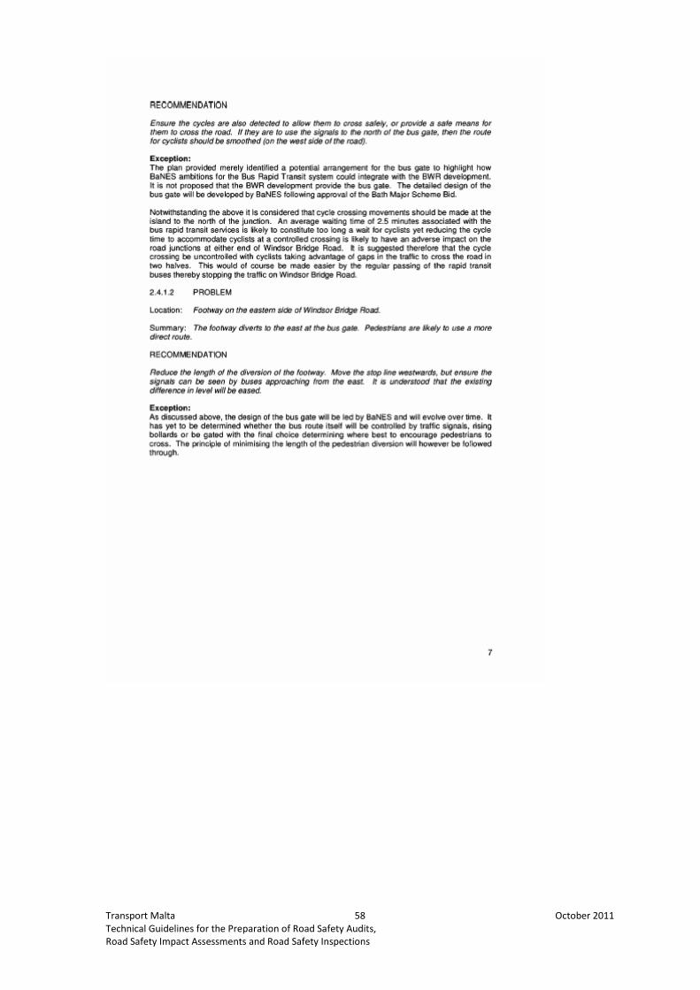
Transport Malta 58 October 2011
Technical Guidelines for the Preparation of Road Safety Audits,
Road Safety Impact Assessments and Road Safety Inspections

Transport Malta 59 October 2011
Technical Guidelines for the Preparation of Road Safety Audits,
Road Safety Impact Assessments and Road Safety Inspections
Annex 3: Road Accidents Typology Catalogue
(World Road Association PIARC Technical Committee, 2007)
Figure 1 : Road Accidents Typology Catalogue

Transport Malta 60 October 2011
Technical Guidelines for the Preparation of Road Safety Audits,
Road Safety Impact Assessments and Road Safety Inspections
Annex 4: Signs and Symbols Used In Collision Diagrams
(Asian Development Bank, 1998)
Figure 2 : Signs and Symbols in Collision Diagrams

Transport Malta 61 October 2011
Technical Guidelines for the Preparation of Road Safety Audits,
Road Safety Impact Assessments and Road Safety Inspections
Annex 5: Vehicle Movement Codes Used In New Zealand
(World Road Association PIARC Technical Committee, 2007)
Figure 3 : Vehicle Movement Codes used in New Zealand

Transport Malta 62 October 2011
Technical Guidelines for the Preparation of Road Safety Audits,
Road Safety Impact Assessments and Road Safety Inspections
Annex 6: Possible Links among Accidents Types, Cause Of
Accident and Lead Deficiency
(World Road Association PIARC Technical Committee, 2007)
Type Group 0
Personal road accidents
Major Accidents Causes
Speeding
Road Deficiency
Non-homogeneous roadways, sudden changes in road arrangements, sudden
changes in road alignment, poor optical alignment, inappropriate road cross-section,
sudden change of road surface, poor quality of road surface.
Potential Improvements Measures
Removal of non-homogeneous road sections, improved optical parameters of
horizontal curves, corrected road cross-section, reconstruction of road surfaces,
speed reduction measures, appropriate road signing and marking.
Type Group 1
Road accidents of vehicles driving in the same direction outside of junctions
Major Accidents Causes
Speeding
Road Deficiency
Major difference in vehicle speeds, short following distances between vehicles,
inappropriate horizontal and vertical road alignment, poor distance estimation, poor
road surface.
Potential Improvements Measures
Construction measures to reduce speed, road reconstruction, reconstruction of road
surface, appropriate road signing and marking.
Type Group 2
Road accidents of oncoming vehicles outside of intersections
Major Accident Causes
Speeding, illegal or inadvisable overtaking.
Road Deficiency
Non-homogeneous road, optical illusions, poor distance estimation, inappropriate
road signing and marking.

Transport Malta 63 October 2011
Technical Guidelines for the Preparation of Road Safety Audits,
Road Safety Impact Assessments and Road Safety Inspections
Potential Improvements Measures
Construction measures to reduce speeds, road reconstruction (greater visual
distance of oncoming vehicles in horizontal curves), reconstruction of road surface,
appropriate road signing and marking.
Type Group 3
Road accidents of vehicles entering junction from the same corridor.
Major Accident Causes
High speed of vehicles entering junctions, insufficient lane width distance between
vehicles, blind angles.
Road Deficiency
Inappropriate junction layouts, ambiguous channelization – inappropriate guidance
in junctions, single-track vehicles (motorcycles, ect.) overtaking in junctions.
Potential Improvement Measures
Easily decipherable junction layouts, consistent road marking and signing with
conspicuous design information, or construction measures (e.g. traffic islands)
delineating vehicle paths.
Type Group 4
Road accidents of vehicles entering intersections from opposite corridors.
Major Accident Causes
Failure to give way to oncoming vehicles, psychological pressure on drivers,
erroneous speed and distance estimations of incoming vehicles.
Road Deficiency
Inappropriate intersections layout, ambiguous channelisation – inappropriate
guidance information.
Potential Improvement Measures
More decipherable junction layout, consistent road marking delineating vehicle
paths, installation of turning lanes (particularly for left turning), traffic signal
installation.
Type Group 5
Road accidents of vehicles entering junction form neighbouring corridors.
Major Accident Causes
The high speed of vehicles entering intersections, insufficient sight distance, effects
of psychological rights of way, failure to comply with traffic light signals in traffic-
controlled intersections.
Road Deficiency
Inappropriate intersection layout, contradiction between actual and psychological
right of way, obstacles in sight triangles, poor intersections lightning, ambiguous

Transport Malta 64 October 2011
Technical Guidelines for the Preparation of Road Safety Audits,
Road Safety Impact Assessments and Road Safety Inspections
channelization – inappropriate guidance at intersections, obscured road signs,
insufficient visibility of road signs.
Potential Improvement Measures
More conspicuous intersection layout, consistent road marking or construction
measures (e.g. traffic islands) delineating vehicle paths, installations of clear road
signing and marking.
Type Group 6
Accidents between vehicles and pedestrians.
Major Accident Causes
Failure of drivers or pedestrians to comply with traffic light signals, insufficient
optical contact, disrespect for pedestrian rights of way, forcing the right of way
inappropriately.
Road Deficiency
Insufficient layout of pedestrian pavement and crossings, insufficient separation of
pedestrians from motorised traffic, missing pavement width, missing refuge islands.
Potential Improvements Measures
Sensible layout of pedestrian pavements and crossings at heavy pedestrian traffic
sites, installation of refuge islands to protect pedestrians, construction measures to
improve visibility, traffic calming at the perimeters of pedestrian zones.
Type Group 7
Road accidents with standing parked vehicles.
Major Accident Causes
Driver inattention, inappropriate location of parking sites and their exists.
Roar Deficiency
Inappropriate widths of road shoulders and parking lanes, inappropriate location of
parking site exits, poor cycle lane geometry.
Potential Improvement Measures
Better separation of moving and standing vehicles, minimized number of parking site
exists and their concentration on single collector roads.
Type Group 8
Road accidents with animals and rail vehicles.
Major Accident Causes
Failure to apply with warning light signals announcing oncoming rail vehicles.
Road Deficiency
Existence of crossing at grade on roads with high traffic volumes, insufficient sight
distances, faulty warning light signals, insufficient fencing to prevent animals from
the road.

Transport Malta 65 October 2011
Technical Guidelines for the Preparation of Road Safety Audits,
Road Safety Impact Assessments and Road Safety Inspections
Potential Improvement Measures
Building of grade-separated crossing of roads and railways, upgrading technological
equipment at railways crossing, improved sight distance, installation of fences along
roads at sites of higher animal traffic, building bio-corridors.

Transport Malta 66 October 2011
Technical Guidelines for the Preparation of Road Safety Audits,
Road Safety Impact Assessments and Road Safety Inspections
Annex 7: Comparative Testing
As adapted from the TMS Consultancy Course Notes for Road Safety Engineering and
Road Safety Audit
Poisson Test
Example: Table 4 : Comparative Testing - Poisson Test
Year Number of Accidents
1 1
2 0
3 5
Long Term Average (μ) = (1 + 0 + 5)/3 = 2
What is the likelihood of getting 5 collisions when the long term average is 2 ?
• Go to the Poisson Tables – Single Factor Values
• Go to the column where μ = 2 and take the value for the x = 5
• From tables, the chance of 5 collisions occurring is 0.0361 = 3.6%
What is the likelihood of getting 5 or more collisions ?
• Go to the Poisson Tables – Cumulative Factor Values
• Go to the column where μ = 2 and take the value for the x = 5
• From tables, the chance of getting 5 or more collisions is 0.0526 = 5.26%
Significance Level Confidence Level % Interpretation
1 99 Highly acceptable
5 95 Acceptable
10 90 Fair
20 80 Indicative
Result:
• There is a 3.6% likelihood of having 5 collisions purely by chance
• There is a 96.4% confidence that there is a real change in the collision at this
location which value is interpreted as being an acceptable level of
confidence.
• There is a 5.26% likelihood of having 5 or more collisions purely by chance
• There is a 94.74% confidence that there is a real change in the collision at
this location which value is interpreted as being an acceptable level of
confidence.

Transport Malta 67 October 2011
Technical Guidelines for the Preparation of Road Safety Audits,
Road Safety Impact Assessments and Road Safety Inspections
Figure 4 : Poisson Probabilities - Single Factor Values

Transport Malta 68 October 2011
Technical Guidelines for the Preparation of Road Safety Audits,
Road Safety Impact Assessments and Road Safety Inspections
Figure 4: Poisson Probabilities – Single Factor Values (cont)

Transport Malta 69 October 2011
Technical Guidelines for the Preparation of Road Safety Audits,
Road Safety Impact Assessments and Road Safety Inspections
Figure 4: Poisson Probabilities – Single Factor Values (cont)

Transport Malta 70 October 2011
Technical Guidelines for the Preparation of Road Safety Audits,
Road Safety Impact Assessments and Road Safety Inspections
Figure 5 : Poisson Probabilities - Cumulative Factor Values

Transport Malta 71 October 2011
Technical Guidelines for the Preparation of Road Safety Audits,
Road Safety Impact Assessments and Road Safety Inspections
Figure 5: Poisson Probabilities – Cumulative Factor Values (cont)

Transport Malta 72 October 2011
Technical Guidelines for the Preparation of Road Safety Audits,
Road Safety Impact Assessments and Road Safety Inspections
Figure 5: Poisson Probabilities – Cumulative Factor Values (cont)

Transport Malta 73 October 2011
Technical Guidelines for the Preparation of Road Safety Audits,
Road Safety Impact Assessments and Road Safety Inspections
Chi-Square (x2) Test
Example: Table 5 : CHi-Square (x
2) Test Example
Site Control Total
Dark 10 a 70 c 80 g
Light 5 b 165 d 170 h
Total 15 e 235 f 250 N
x2 = [ (|ad - bc| - N/2)
2 N ] / efgh = 7.2
What is the probability that an accident occurs in the dark due to random
fluctuation ?
• Go to the Chi 2 Distribution Tables
• For a value of v = 1, find the closest value of x2 = 7.2
• Read off the probability value α = between 0.01 and 0.005, hence between
1% and 0.5%
Result:
• The probability that there is an accident occurring during the dark due to
random fluctuation is less than 1%
• There is a 99% of a real difference is risk between site and control and this
value is interpreted as being a highly acceptable level of confidence.
Figure 6 : The CHi2 Distribution
Transport Malta 74 October 2011
Technical Guidelines for the Preparation of Road Safety Audits,
Road Safety Impact Assessments and Road Safety Inspections
Annex 8: Toolbox for Road Safety Interventions
- Pedestrian Crossing and Raised Pedestrian Crossing
- School Ahead Warning Signs and Road Markings
- Pedestrian Railings and U-Bars
- Pedestrian Footways
- Cycle Lanes
- Provision for Alighting/Boarding
- One-Ways and Access Restrictions
- Traffic Mirrors
- Rumble Strips

Transport Malta 75 October 2011
Technical Guidelines for the Preparation of Road Safety Audits,
Road Safety Impact Assessments and Road Safety Inspections
Pedestrian Crossing and Raised Pedestrian Crossing
Aims of Measure:
To improve road safety by provide a safe crossing area
Implementation of Measure:
• identification of the road crossing based on a pedestrian behavioral setting
survey
• implementation of the pedestrian crossing including all signage and
carriageway markings as per standard specifications
• the measure may include pedestrian railings as required
• anti-skid material may be applied on the immediate approach to the
pedestrian crossing
• The types of pedestrian crossings used are as follows, thus:
Table 6 : Pedestrian Crossing Characteristics
Type of Crossing Characteristics
Zebra • Path across a road where pedestrians may cross;
• Marked with black and white stripes;
• White zig-zag lines for 15metres before the crossing;
• Give-way line at 1000mm from the crossing;
• Black and white poles with flashing orange beacons (Belisha);
• Minimum of 200metres between successive crossings;
• For 50km/h road speed the minimum visibility is 65m;
• For 65km/h road speed the minimum visibility is 100m;
• For 80km/h road speed the minimum visibility is 150m;
• For road widths greater than 11m, a refuge island should be constructed and must include
a lighted bollard at each end;
• A staggered refuge layout is optional where the carriageway is between 11m – 15m wide,
but is essential for carriageways greater than 15m;
• On roads with a speed greater than 55km/h, additional primary signals should be
provided.
Pelican • Signal-controlled crossing;
• Operated by pedestrians;
• White zig-zag lines for 15metres before the crossing;
• Minimum of 200metres between successive crossings;
• For 50km/h road speed the minimum visibility is 65m;
• For 65km/h road speed the minimum visibility is 100m;
• For 80km/h road speed the minimum visibility is 150m;
• For road widths greater than 11m, a refuge island should be constructed and must include
a lighted bollard at each end;
• A staggered refuge layout is optional where the carriageway is between 11m – 15m wide,
but is essential for carriageways greater than 15m;
• On roads with a speed greater than 55km/h, additional primary signals should be
provided.

Transport Malta 76 October 2011
Technical Guidelines for the Preparation of Road Safety Audits,
Road Safety Impact Assessments and Road Safety Inspections
Figure 7 : Raised Zebra Crossing
Warning Signs and Road Markings
Aims of Measure:
To improve road safety by providing advance warning signs and road markings to
vehicular drivers on the approach to hazardous locations
Implementation of Measure:
• identification of the hazardous location
• determination of the location of the appropriate signage road markings
SIGN
Figure 8 : Road Markings / Approach to School
Pedestrian Railings and U-Bars
Aims of Measure:
To improve road safety by implementing measures which guide pedestrians to
specific safe locations.
Implementation of Measure:
• identification of potential hazardous locations based on a pedestrian
behavioral settings survey
• identification of location/s for the implementation of the pedestrian
railings/U-Bars and their extent
• implementation of measure
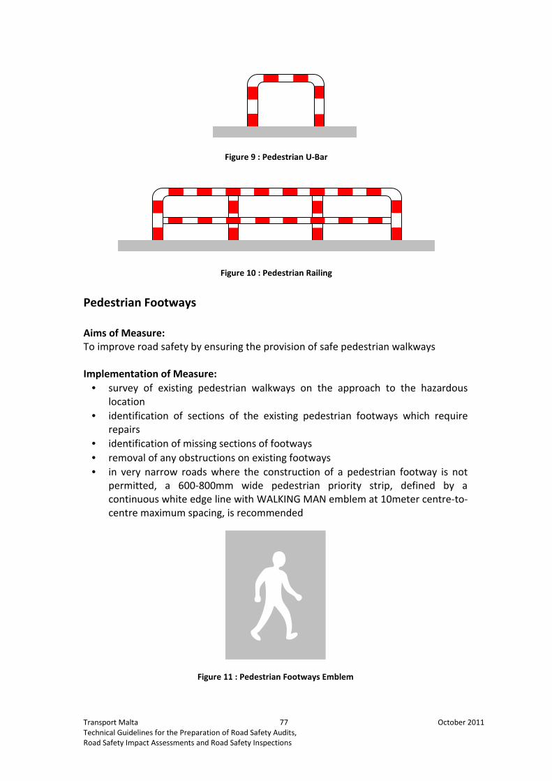
Transport Malta 77 October 2011
Technical Guidelines for the Preparation of Road Safety Audits,
Road Safety Impact Assessments and Road Safety Inspections
Figure 9 : Pedestrian U-Bar
Figure 10 : Pedestrian Railing
Pedestrian Footways
Aims of Measure:
To improve road safety by ensuring the provision of safe pedestrian walkways
Implementation of Measure:
• survey of existing pedestrian walkways on the approach to the hazardous
location
• identification of sections of the existing pedestrian footways which require
repairs
• identification of missing sections of footways
• removal of any obstructions on existing footways
• in very narrow roads where the construction of a pedestrian footway is not
permitted, a 600-800mm wide pedestrian priority strip, defined by a
continuous white edge line with WALKING MAN emblem at 10meter centre-to-
centre maximum spacing, is recommended
Figure 11 : Pedestrian Footways Emblem

Transport Malta 78 October 2011
Technical Guidelines for the Preparation of Road Safety Audits,
Road Safety Impact Assessments and Road Safety Inspections
Cycle Lanes
Aims of Measure:
To improve road safety by ensuring the provision of cycle lanes
Implementation of Measure:
• implementation of modal choice survey
• analysis of modal choice survey
• identify the roads used for cycling
• identification of sections of the existing approach roads where it is safe to
include a cycle lane
• identification of any necessary repair works to the road surface
• implementation of cycle lane
General Criteria for Route Selection and Planning
The selection of the cycle route depends on various factors and based on the
following analysis, thus:
• Identification of bicycle trip generation within a 5 –10km circuit;
• The linking of scenic, recreational and functional potential of the route to
promote its use in the broadest sense;
• Identification of routes that are free from heavy traffic and are well surfaced;
• Identification of parking areas, both for passenger vehicles and for bicycles,
along the route;
• Identification of areas with climate extremes, such as wing traps;
• Mapping and investigating the route conditions, including:
- Uphill gradients/distance ratios;
- Potential for uninterrupted cycle routes;
- Available width to accommodate the cycle route and all necessary
signage, lighting and resting areas;
- Identification of nodes of vehicular conflict and physical barriers.
Recommended Widths for Cycle Routes
The following table outlines the recommended width for various classification and
usage of cycle routes, hence:
Table 7 : Recommended Widths for Cycle Routes
ROUTE WIDTH
(metres)
Cycle Lanes
One Way 1.00-2.00
Two Way 1.50-3.60
Design Elements
The main points of design are as follows, thus:
• Surface materials are to be durable and easy to maintain;
• The pavement and bikeway is to have positive drainage with a minimum of
2% cross-slope. All drainage structures are to be located off the cyclepath;

Transport Malta 79 October 2011
Technical Guidelines for the Preparation of Road Safety Audits,
Road Safety Impact Assessments and Road Safety Inspections
• Traffic control/ information systems facilitate the use of the cyclepath. These
include signage and pavement markings and are to be as follows, thus:
- Sign posts are to be set-back a minimum of 900mm from the edge of
the path and any bottom sign edge should be set at 1.5 – 2.1metres
above the finished level of the path to allow for adequate visibility;
- Signage is to be kept at a minimum;
- Signs are to be used to mark out and delineate routes, to regulate
the path usage, and provide all necessary safety/approach warnings.
• Adequate lighting and street furniture is to be installed along the paths and at
intersections. The criteria are as follows:
- Lighting is to be from 6 – 10 lux;
- The location of lighting and street furniture is to be according to a
fixed design to act as embellishment;
- All street furniture is to be set-back from the cycle path so as to
prevent points of conflict.
Figure 12 : Typical Signage Layout for Cycle Routes
One-Ways and Access Restrictions
Aims of Measure:
To improve road safety by managing the traffic volumes and direction on the road
network
Implementation of Measure:
• survey of existing traffic patterns and traffic volumes
in the area

Transport Malta 80 October 2011
Technical Guidelines for the Preparation of Road Safety Audits,
Road Safety Impact Assessments and Road Safety Inspections
• identification of streets which can be made one-way
• identification of streets which may be closed off for
vehicular traffic
• identification of adequate alternative routes to
support one-way systems and/or road closures
• identification of any necessary upgrading measures
at junctions to support one-way systems and/or road
closures
• re-design and implementation of road signage to
support one-way systems and/or road closures
• a road closure is not recommended if such would
result in traffic circulation problems in the locality
since such would create other road safety hazards in
itself
Figure 13 : One – Way or Restricted Access Sign
Traffic Mirrors
Aims of Measure:
To improve road safety by improving visibility lines
Implementation of Measure:
• analysis of existing traffic patterns in the area
• analysis of visibility lines at sensitive locations
• identification of locations where traffic mirrors are required
• the placing of the traffic mirror is not to create prejudice is created to third
party rights
• The mirror is to be located at the standard height in relation to the finished
footway level
• The mirror is to be angled such that appropriate and maximum visibility is
obtained

Transport Malta 81 October 2011
Technical Guidelines for the Preparation of Road Safety Audits,
Road Safety Impact Assessments and Road Safety Inspections
Rumble Strips
Aims of Measure:
To alert the driver that he is approaching a traffic sensitive area
Implementation of Measure:
• survey of existing traffic patterns and traffic volumes in the area
• identification of locations where rumble strips can be effective
• Rumble strips are to be located at 200m on the approach to the traffic
sensitive area;
• the length of the rumble strips depends on the width of the road;
• for the safety of cyclists, a clear gap of 75mm-1000mm is to be left between
the rumble strips and the footway;
• for rumble strips sited 200m away from a residential area, they are not to
exceed 10mm in height and no vertical face is to exceed 6mm in height;
• for rumble strips sited within a residential area, they are not to exceed 5mm
in height and no vertical face is to exceed 4mm in height;
Figure 14 : Rumble Strips

Transport Malta 82 October 2011
Technical Guidelines for the Preparation of Road Safety Audits,
Road Safety Impact Assessments and Road Safety Inspections
Annex 9: Toolbox for Speed Control Measures
- Speed Limit
- Dragons’ Teeth
- Yellow Bar Markings
- Round Topped Road Humps
- Road Thumps
- Build-outs/Pinch Points
- Chicanes
- Mini Roundabout and Traffic Islands
- Speed Cushions
- Lane Narrowing
- Gateways

Transport Malta 83 October 2011
Technical Guidelines for the Preparation of Road Safety Audits,
Road Safety Impact Assessments and Road Safety Inspections
Traffic Calming: Speed Limit
Aims of Measure:
To improve road safety by reducing the vehicle speeds
Implementation of Measure:
• identification of the main school routes and the extent of the area of
influence
• determination of the revised speed limit
• implementation of SPEED LIMIT sign, repeater signs and the corresponding
END OF SPEED LIMIT sign
• implementation of speed roundels
• implementation of REDUCE SPEED NOW signs
• SLOW road markings
Figure 15 : Speed Limit Signage
Figure 16 : Speed Limit Road Markings

Transport Malta 84 October 2011
Technical Guidelines for the Preparation of Road Safety Audits,
Road Safety Impact Assessments and Road Safety Inspections
DRAGONS’ TEETH
Aims of Measure:
To reduce the speed of vehicles proceeding towards speed sensitive areas
Implementation of Measure:
• identification of the speed sensitive locations
• implementation of Dragons’ Teeth road markings
• complement speed reduction measures
• may be used a part of a gateway design
• the dimensions of the Dragons’ Teeth have a width of 750mm and they
increase in height in the direction of traffic from 600mm to 1000mm but
retain the centre-to-centre spacing of 1500mm
Figure 17 : Dragon's Teeth Road Markings
MINI ROUNDABOUTS AND TRAFFIC ISLANDS
Aims of Measure:
To reduce vehicular speeds and to regularise and manage vehicle movements.
Implementation of Measures according to standard specifications:
• measure can be implemented on straight roads to break up the road into
sections
• measure can be implemented at T-junctions, Y-junctions and at crossroads
• the mini roundabout, with a diameter not exceeding a maximum of
4.0meters, may be either painted or constructed as a mountable round area
with a crest height not exceeding a maximum of 100mm
• the mini roundabout is recommended for locations where the external
diameter does not exceed 28meters

Transport Malta 85 October 2011
Technical Guidelines for the Preparation of Road Safety Audits,
Road Safety Impact Assessments and Road Safety Inspections
YELLOW BAR MARKINGS
Aims of Measure:
To reduce the speed of vehicles proceeding towards speed sensitive areas
Implementation of Measure:
• identification of the speed sensitive locations
• implementation of Yellow Bar Markings
• complement speed reduction measures
• may be used a part of a gateway design
• the Bar Markings have a width of 200mm and their centre-to-centre spacing
decreases in the direction of traffic
Table 8 : Spacing of Yellow Bar Markings on the road
Bar
No
Distance
from D1
(m)
Bar
No
Distance
from D1
(m)
Bar
No
Distance
from D1
(m)
Bar
No
Distance
from D1
(m)
Bar
No
Distance
from D1
(m)
D1 0.00 D21 60.10 D41 133.75 D61 224.70 D81 338.15
D2 2.75 D22 63.45 D42 137.85 D62 229.80 D82 344.65
D3 5.50 D23 66.80 D43 142.00 D63 234.90 D83 351.35
D4 8.25 D24 70.15 D44 146.15 D64 240.10 D84 358.30
D5
11.05 D25 73.60 D45 150.40 D65 245.40 D85 365.50
D6 13.90 D26 77.05 D46 154.65 D66 250.70 D86 373.20
D7 16.80 D27 80.55 D47 158.95 D67 256.10 D87 380.90
D8 19.70 D28 84.10 D48 163.35 D68 261.50 D88 388.60
D9 22.60 D29 87.65 D49 167.75 D69 267.00 D89 396.25
D10 25.55
D30 91.30 D50 172.25 D70 272.60 D90 403.95
D11 28.55 D31 94.95 D51 176.75 D71 278.20
D12 31.60 D32 98.65 D52 181.30 D72 283.90
D13 34.65 D33 102.40 D53 185.95 D73 289.60
D14 37.70 D34 106.15 D54 190.60 D74 295.45
D15 40.80
D35 110.00 D55 195.35 D75 301.30
D16 43.95 D36 113.85 D56 200.10 D76 307.25
D17 47.15 D37 117.75 D57 204.90 D77 313.30
D18 50.35 D38 121.70 D58 209.80 D78 319.35
D19 53.55 D39 125.65 D59 214.70 D79 325.55
D20 56.80 D40 129.70 D60 219.70 D80 331.75
Figure 18 : Yellow Bar Markings

Transport Malta 86 October 2011
Technical Guidelines for the Preparation of Road Safety Audits,
Road Safety Impact Assessments and Road Safety Inspections
ROUND TOPPED ROAD HUMPS
Aims of Measure:
To reduce the speed of vehicles proceeding towards speed sensitive areas
Implementation of Measure:
• identification of the speed sensitive locations
• implementation of Round Topped Road Hump
• complement speed reduction measures
• for two-way roads, the road hump should not be implemented within the
15m distance from the corner
• for one-way roads, the road hump should not be implemented within the 5m
distance from the corner
• if the street is a bus route, the crest of the hump is not to exceed 50mm
• if the street is not a bus route, the crest of the hump is not to exceed 100mm
• the hump width is to be 3.7m
• the hump is not to impede or obstruct access to garages
• adequate width is to be allowed between the edge of the carriageway and
the edge of the hump to permit unimpeded flow of rainwater drainage
Figure 19 : Specifications for Round-Topped Road Hump
Figure 20 : Line Markings and Signage for Round-Topped Road Hump

Transport Malta 87 October 2011
Technical Guidelines for the Preparation of Road Safety Audits,
Road Safety Impact Assessments and Road Safety Inspections
BUILD-OUTS/PINCH POINTS
Aims of Measure:
To reduce vehicular speeds
Implementation of Measure:
• narrowing of the road
• re-organisation of on-street parking
• may include a pedestrian crossing
• identification of the speed sensitive locations
• implementation of the pinch point/build-outs
• complement speed reduction measures
• effective road width to be determined depending on the road classification
• the pinch point/build-out is not to impede or obstruct access to garages
• the pinch point/build-out is to permit unimpeded flow of rainwater drainage
• may include soft landscaping not exceeding 50mm in height
• may include a raised pedestrian crossing depending on the location of the
measure and the vehicle flow direction of the road
Figure 21 : Build Outs

Transport Malta 88 October 2011
Technical Guidelines for the Preparation of Road Safety Audits,
Road Safety Impact Assessments and Road Safety Inspections
CHICANES
Aims of Measure:
To reduce vehicular speeds
Implementation of Measure:
• identification of the speed sensitive locations
• implementation of the pinch point/build-outs
• complement speed reduction measures
• effective road width to be determined depending on the road classification
• the pinch point/build-out is not to impede or obstruct access to garages
• the pinch point/build-out is to permit unimpeded flow of rainwater drainage
• may include soft landscaping not exceeding 50mm in height
• may include a deflection in the road alignment
• narrowing of the road
• on-street parking arrangements with the chicane will depend on the
dimensions of the chicane, the 85th
percentile vehicle speed and the traffic
volumes
Figure 22 : Chicanes

Transport Malta 89 October 2011
Technical Guidelines for the Preparation of Road Safety Audits,
Road Safety Impact Assessments and Road Safety Inspections
SPEED CUSHIONS
Aims of Measure:
To reduce vehicular speeds of passenger cars
Implementation of Measure:
• the speed cushions are to be constructed as per dimensions outlined in the
illustration
• the distance between the speed cushions is such that the axle of the
passenger vehicle is effected by the cushions however, the wider axle of
heavy vehicles and public transport vehicles is not effected
Figure 23 : Speed Cushions
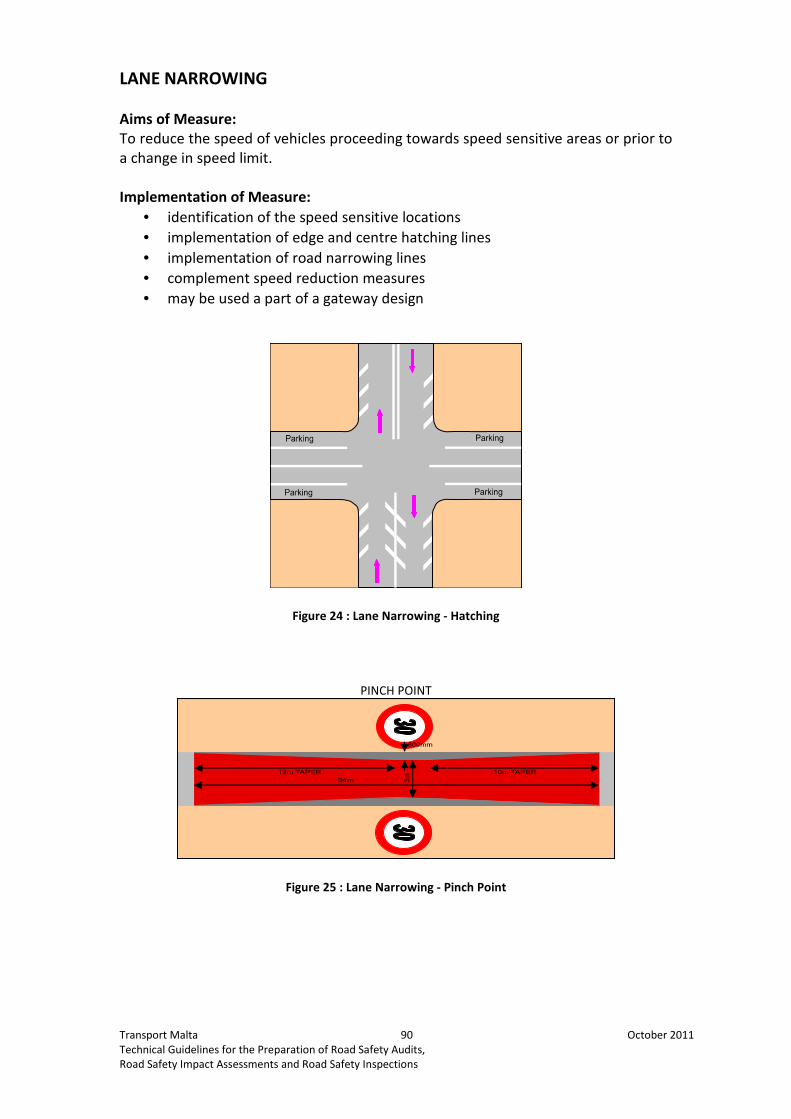
Transport Malta 90 October 2011
Technical Guidelines for the Preparation of Road Safety Audits,
Road Safety Impact Assessments and Road Safety Inspections
LANE NARROWING
Aims of Measure:
To reduce the speed of vehicles proceeding towards speed sensitive areas or prior to
a change in speed limit.
Implementation of Measure:
• identification of the speed sensitive locations
• implementation of edge and centre hatching lines
• implementation of road narrowing lines
• complement speed reduction measures
• may be used a part of a gateway design
Figure 24 : Lane Narrowing - Hatching
PINCH POINT
Figure 25 : Lane Narrowing - Pinch Point

Transport Malta 91 October 2011
Technical Guidelines for the Preparation of Road Safety Audits,
Road Safety Impact Assessments and Road Safety Inspections
GATEWAYS
Aims of Measure:
To reduce the speed of vehicles proceeding towards speed sensitive areas or prior to
a change in speed limit.
Implementation of Measure:
• identification of the 85th
percentile speed of the road
• identification of location for gateway
• recommended for implementation on arterial and distributor roads, roads
with linking functions and roads within the village which have high traffic
volumes
• gateways are a combination of road safety measures complementing each
other for maximum effectiveness
Figure 26 : Gateway including Hatching, Anti-Skid Material, Speed Limit and Central Island
Figure 27 : Gateway including Hatching, Dragons' Teeth, Speed Limit,
Rumble Strips and Central Island
Figure 28 : Gateway including Road Narrowing,
Anti-Skid Material and Speed Limit

Transport Malta 92 October 2011
Technical Guidelines for the Preparation of Road Safety Audits,
Road Safety Impact Assessments and Road Safety Inspections
Annex 10: Checklist for Road Safety Inspections
(TMS Consultancy, 2011)
Table 9 : Checklist for Road Safety Inspection
Characterisation No. Question Yes
�
No
�
Comments
0 Have eventual final audit
result from previous audit
phase been taken into
consideration?
1 Are there any issues from
accident date if available?
2 Are there specific traffic
composition characteristics to
be taken into consideration?
3 Are special measures required
for particular groups e.g. for
young people, older people,
sick people, physically
handicapped, hearing-
impaired or blind people?
4 Is the design of the road
according to its function and
hierarchy in the network?
5 Are there build up areas with
mixed traffic?
6 Is access to abutting
properties and agriculture
appropriate for road safety?
7 Are there any parallel ways to
be used by cats and farm
equipment?
1. Function,
operating elements
and surroundings
8 Do we realize the change of
functions and characteristics
early enough?
100km/h > 300 m ahead
80km/h > 200 m ahead
50 km/h > 150 m ahead
9 Are there anywhere
accumulations of events such
as curves + hilltops +
Intersection etc?
10 Are transitions installed
between different functions
and road characteristics?
11 Are there traffic islands and
lane shifts at the entrance of
villages and towns
12 Are speed limits and traffic
calming measures in villages

Transport Malta 93 October 2011
Technical Guidelines for the Preparation of Road Safety Audits,
Road Safety Impact Assessments and Road Safety Inspections
Characterisation No. Question Yes
�
No
�
Comments
and towns required and
applied in the same way?
13 Can road maintenance service
vehicles be parked safely?
14 Is stopping sight distance
guaranteed along the entire
section?
100 km/h > 185 m for trucks
80 km/h > 130m for trucks
60 km/h > 85m for trucks
15 Is the landscaping work
finished?
16 Are all fixed or painted
obstacles that can be
dangerous placed outside the
safety zone? 100 km/h >9m
80km/h > 6 m
60km/h > 3 m (away from
skidding cars?)
17 Is the transition from a built-
up to a rural road or from an
Illuminated to a not
Illuminated road appropriately
designed (village/town
outskirts)?
18 Is the end of the construction
area away from critical points,
e.g. summits, downgrades,
curves, areas with restricted
sight distance or distractions?
1 Is the cross section
appropriate to the function?
2 Does the road surface provide
the required grip over the long
term where small radii occur
(e.g. also on ramps)?
3 Are there any doubts
regarding the surface grip
because of excess bleeding or
polished components?
4 Is the surface even and free
from grooves?
5 Is the surface free from short
or long waves?
6 Is there sufficient drainage for
the road and its surroundings?
2. Cross Section
7 Is there sufficient
cross/diagonal fall ?
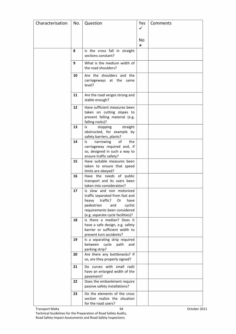
Transport Malta 94 October 2011
Technical Guidelines for the Preparation of Road Safety Audits,
Road Safety Impact Assessments and Road Safety Inspections
Characterisation No. Question Yes
�
No
�
Comments
8 Is the cross fall in straight
sections constant?
9 What is the medium width of
the road shoulders?
10 Are the shoulders and the
carriageways at the same
level?
11 Are the road verges strong and
stable enough?
12 Have sufficient measures been
taken on cutting slopes to
prevent falling material (e.g.
falling rocks)?
13 Is stopping straight
obstructed, for example by
safety barriers, plants?
14 Is narrowing of the
carriageway required and, if
so, designed in such a way to
ensure traffic safety?
15 Have suitable measures been
taken to ensure that speed
limits are obeyed?
16 Have the needs of public
transport and its users been
taken into consideration?
17 Is slow and non motorized
traffic separated from fast and
heavy traffic? Or have
pedestrian and cyclist
requirements been considered
(e.g. separate cycle facilities)?
18 Is there a median? Does it
have a safe design, e.g. safety
barrier or sufficient width to
prevent turn accidents?
19 Is a separating strip required
between cycle path and
parking strip?
20 Are there any bottlenecks? If
so, are they properly signed?
21 Do curves with small radii
have an enlarged width of the
pavement?
22 Does the embankment require
passive safety installations?
23 Do the elements of the cross
section realize the situation
for the road users?

Transport Malta 95 October 2011
Technical Guidelines for the Preparation of Road Safety Audits,
Road Safety Impact Assessments and Road Safety Inspections
Characterisation No. Question Yes
�
No
�
Comments
1 Is the existing speed limit
adequate for the horizontal
and vertical elements of the
alignment?
Alignment
2 Is sight obstructed, for
example by safety barriers,
fences, road equipment,
parking areas, traffic signs,
landscaping/ greenery, bridge
abutments, buildings?
4 Is visibility in curves ensured?
5 Is the super elevation in curves
sufficient
6 Are there sufficient overtaking
possibilities
7 Has the uphill sector a passing
lane for overtaking slow
traffic?
8 Has the passing lane a
sufficient length in order to
ensure that the vehicle can
overtake and return safety?
9 Are there hidden dips in the
vertical alignment?
10 Is the alignment consistent
and easily recognized by the
road users? Or full of surprises
for the drivers?
11 Are changes (surprises)
indicated by the transitions
like signing, points of fixation?
12 Are the outside of the curves
framed parallel and
consistent?
13 Are the insides of the curves
free from side obstructions?
14 Are there optical illusions ?
1 Are the intersections
perpendicular?
2 Is the main direction clearly
recognizable? And if so, is the
right of way clearly
recognizable?
4. Intersections
4.1 Geometry
And lay out
3 Are the movements guided
clearly and easily to
understand? Are traffic flows
guided by marking?

Transport Malta 96 October 2011
Technical Guidelines for the Preparation of Road Safety Audits,
Road Safety Impact Assessments and Road Safety Inspections
Characterisation No. Question Yes
�
No
�
Comments
4 Are the auxiliary lanes or
tapers for turning movements
large enough?
5 Is the intersection fully visible
and recognizable in time from
all approaches for different
driver eye heights of: Cars,
trucks, motorcycles, bicycles,
etc; and are the required sight
triangles clear?
6 Does the ambient lighting
present any special
requirements?
7 Is sight obstructed, for
example by safety barriers,
fences, road equipment,
parking areas, traffic signs,
landscaping/greenery, bridge
abutments, buildings?
8 Are type and designs of the
intersections suitable for the
function and traffic volume of
the intersecting roads?
(Separate answers for each
intersection?)
9 A pedestrian/cyclist routing at
the intersections adapted to
the actual conditions and
clearly marked and
signposted?
10 Are all approaches equipped
with pedestrian and cycle
crossing?
11 Has right of way been
specified and clarified at cycle
crossings, in particular for
cycle paths that are set back?
12 Is the transition safely
designed if footpaths end on
an intersection or road or are
directed across the road?
13 Are stop lines for motorists
further back for the benefit of
cyclists?
14 Have suitable measures been
taken to ensure that speed
limits are obeyed?
15 Are there no-stopping zones?
16 Is a reduction in speed
required in the direction of the
intersection? And are there

Transport Malta 97 October 2011
Technical Guidelines for the Preparation of Road Safety Audits,
Road Safety Impact Assessments and Road Safety Inspections
Characterisation No. Question Yes
�
No
�
Comments
transitions for speed
reductions on the minor road?
17 Does the obligation to yield
right of way need to
reinforced (e.g. using
repetition?)
18 Are pedestrian crossings
clearly marked? Is each
section equipped with signals
(including railway structures)?
19 Are the crossings for
pedestrian and cyclists
provided with low kerbs?
20 Should turns be prohibited
(block diversions)?
21 Are the type of spacing of
different crossing installations
coordinated (e.g. traffic
signals, zebra crossings)?
22 Is right of way clearly defined
at points where cyclists come
into contact with each other
or with motorized traffic?
23 Are refuges large and wide
enough for crossing
pedestrians and cyclists to
stand and wait?
24 Are the islands above the level
of the carriageway?
25 Are the islands made only by
markings?
26 Are the islands clearly visible
and of a suitable design?
27 Is there a danger of
underestimating speed and
overestimating distance of
crossing vehicles?
28 Are all approaches to
roundabouts perpendicular
and radial to the center?
29 Is the central island of the
round about shaped as a hill?
30 Is the through – visibility
effectively stopped by the
roundabout and the hill?
Roundabouts
31 Is the central island of the
roundabout free from fixed
obstacles which could be
reached by vehicles?

Transport Malta 98 October 2011
Technical Guidelines for the Preparation of Road Safety Audits,
Road Safety Impact Assessments and Road Safety Inspections
Characterisation No. Question Yes
�
No
�
Comments
1 Is the stopping line correlated
with the traffic signal so that
the signal can be seen?
2 Have any turning movements
been excluded from signal
control? If so, is the traffic
management safe?
3 Are traffic signals easily
recognizable?
4 Have cyclists requirements
been considered (e.g. route
through the intersection)?
5 Are stop lines for the
motorists further back for the
benefit of cyclists?
6 Are all the approaches
equipped with pedestrian and
cycle crossings?
4.2 Traffic signals
7 Are pedestrian crossings
clearly constructed? Is each
section equipped with signals
(including railway structures)?
8 Are exclusive green phases
provided for pedestrians and
cyclists where necessary?
9 Can pedestrians cross the road
in one go? Is the green time
sufficient?
10 If there is no exclusive
pedestrian interval provided?
11 Are phase offsets required for
pedestrians and cyclists within
the cycle?
12 Are separate signals provided
for cyclists? (Are the signal
aspects correctly located for
cyclists? Avoid protected turn
phases/risk of cyclists crossing
on red)
13 Is the maximum delay
reasonable for cyclists? Are
cyclists partly or totally
removed from signal control?
14 Are the type and spacing of
different crossing installations
coordinated (e.g. traffic
signals, zebra crossing)?
15 Are the signals are effected at
dawn/dusk by direct sunlight?

Transport Malta 99 October 2011
Technical Guidelines for the Preparation of Road Safety Audits,
Road Safety Impact Assessments and Road Safety Inspections
Characterisation No. Question Yes
�
No
�
Comments
16 Are advanced warnings
provided for traffic signals that
cannot be seen in time?
17 Have the location for the
signals been selected correctly
(additional signals, etc.)?
18 Are secondary signals
provided as necessary?
19 Does the existing road lighting
lead to conflicts in recognizing
the yellow indication (sodium
discharge lamps)?
20 Is access from abutting
properties affected and, if
necessary, included in signal
control?
21 Are perspectives that appear
to be continuous (passage
effect) interrupted by
highlighting the nearest
signals ?
23 Are the traffic signals properly
situated so that they can
distinguished by each
particular traffic flow?
24 Are there any additional signs
correlated with the traffic
signals to show the direction
to which that traffic signal is
referring to?
25 Is the visibility of the traffic
signal ensured on a sunny
day?
26 Is the stopping line correlated
with the traffic signal so that
the signal can be seen?
27 Are the signals covered
/obstructed (e.g. by traffic
signs, lightning masts, plants,
traffic jams)?
1
Are service and rest areas and
parking facilities on both sides
of the road? In case not, are
there left turn lanes?
2 Are there deceleration and
acceleration lanes at the
entrance and exit?
5. Services
5.1 Services and
rest areas
3 Are the dimensions of the
parking areas sufficient for
parking for passenger vehicles,
trucks and buses?

Transport Malta 100 October 2011
Technical Guidelines for the Preparation of Road Safety Audits,
Road Safety Impact Assessments and Road Safety Inspections
Characterisation No. Question Yes
�
No
�
Comments
4 Is the layout of the service or
rest area appropriate for the
different traffic movements?
And if so, is layout suitable in
access areas to and from
property?
5 Is the layout in such a way that
vehicles are running at the
appropriate speed?
6 Are non-stopping zones
provided as necessary?
7 Are the dimensions of the
parking areas sufficient for
parking for passenger vehicles,
trucks and buses?
8 Are parking areas easily
accessible and do they provide
sufficient maneuvering space?
9 Are there any pedestrian
facilities? And if so, are they of
a safe design?
10 Do users feel safe and secure?
11 Have measures been taken to
ensure safe access for rescue
vehicles/maintenance vehicles
fire service?
12 Are sufficient parking areas
provided to minimize illegal
parking on footpaths, cycle
facilities, and on the
carriageway with
corresponding preventative
measures been taken?
13 Are loading areas provided
next to the road where it is
unavoidable?
14 Is it possible to enter and
leave parking areas safely?
15 Is sight obstructed by parking
areas or by illegally parked
vehicles?
5.2 Public Transport 1 Are bus lanes separated from
the vehicle traffic?
6. Needs of
vulnerable Road
Users
6.1 At Public
transport stops
1 Are stops easily and safely
accessible to pedestrians and
are the pedestrians crossings
the rear of the bus stops?

Transport Malta 101 October 2011
Technical Guidelines for the Preparation of Road Safety Audits,
Road Safety Impact Assessments and Road Safety Inspections
Characterisation No. Question Yes
�
No
�
Comments
2 Are the bus stops signposted
and detectable by the drivers?
Is reconcilability guaranteed?
3 Are the bus stops situated
outside of the carriageways
where appropriate?
4 Are areas for waiting
pedestrians and large enough?
5 Are the queuing areas for
waiting passengers sufficient?
6 Is sight obstructed , for
example by safety barriers,
fences, road equipment,
parking areas, traffic signs,
landscaping/greenery, bridge
abutments, buildings?
7 Is cyclist routing safely
designed in the area near
public transport stops?
8 Is lighting required? And if so,
is it appropriately designed?
6.2 Other needs of
pedestrian and
cyclists
1 Are the pedestrian crossings
located where most required
by pedestrian traffic?
3 Have pedestrian crossings
been appointed in such a way
that collective use is
guaranteed and the road will
be not crossed at other
points?
4 Is there a risk of pedestrian
underpasses and bridges being
bypassed? Are suitable
measures in place?
5 Are further crossing aids
required?
6 Are areas for waiting
pedestrians and cyclists
sufficient?
7 Are refuges large and wide
enough for crossing
pedestrians and cyclists to
stand and wait?
10 Is a two-way visual contact
ensured between pedestrians
and motorist?
11 Have cyclists requirements
been considered (e.g. route
across central refuges,
bottlenecks)?

Transport Malta 102 October 2011
Technical Guidelines for the Preparation of Road Safety Audits,
Road Safety Impact Assessments and Road Safety Inspections
Characterisation No. Question Yes
�
No
�
Comments
12 Has priority been giving to
cyclists over other traffic
where necessary?
13 Is the visibility for motorized
traffic adequate to see cyclists
along the road?
14 Are parked vehicles
obstructing the visibility of the
road users regarding cyclists?
15 Are points where cyclists cross
intersecting roads provided
with low curbstones?
16 Are the pedestrian ways
physically separated by kerb
stones, barriers or greenery?
17 Is there a speed limit? And if
so, is it respected by the
drivers?
18 Are there traffic islands at the
entrances of these areas?
19 Are the pedestrian crossings
signposted and detectable by
the drivers?
20 Have pedestrian crossings
been placed in a way that
collective use is guaranteed
and the road will not be
crossed at other points?
21 Are the islands clearly visible
and properly placed?
22 Is lightning provided where
necessary?
6.3 Needs of
Motorcyclists
1 Are motorbikes a remarkable
percentage of the traffic?
2 Have devices or objects that
might destabilize a motorcycle
been avoided on the road
surface?
3 Is the road side clear of
obstructions where
motorcyclists may lean into
curves?
4 Will warning or delineation be
adequate for motorbikes?
5 Have barrier kerbs been
avoided in high speed areas?
6 In areas more likely to have
motorcyclists run off the road
is the roadside forgiving or

Transport Malta 103 October 2011
Technical Guidelines for the Preparation of Road Safety Audits,
Road Safety Impact Assessments and Road Safety Inspections
Characterisation No. Question Yes
�
No
�
Comments
safety shielded?
1 Have appropriate speed limits
been signed appropriately
(start, end, height, location)?
7. Traffic signing,
marking, lightning
7.1 Signing 2 Are there speed limitations of
70/60/50 km/h ahead of
intersections and build up
areas?
3 Is the visibility of the road
course assisted by edge
delineation?
4 Is sight obstructed by the
traffic or by the signs?
5 Is prohibition of overtaking for
trucks, buses, etc.
appropriately designed and
located? Are there warning
signs ahead of the intersection
prohibiting overtaking?
6 Can the signs be clearly
recognized and read (size of
signs)? And do the signs
conform to the conventions of
Vienna and Geneva?
7 Are there more than 2
different traffic signs at one
place and are all traffic signs
necessary?
8 Is a reduction in speed, when
approaching the intersection
,assigned to the correct place
and property designed?
9 Is signing logical and
consistent? Does it show the
right of way clearly?
10 Is signing for service and rest
areas clear?
11 Have variable direction signing
or traffic control systems been
installed and are fully
functional?

Transport Malta 104 October 2011
Technical Guidelines for the Preparation of Road Safety Audits,
Road Safety Impact Assessments and Road Safety Inspections
Characterisation No. Question Yes
�
No
�
Comments
12 Is pedestrian/cyclists routing
at intersections adapted to the
actual conditions and clearly
signposted?
13 Are the installations shared by
pedestrians and cyclists,
including underpasses and
bridges, properly signposted?
14 Is right of way clearly defined
at points where cyclists come
into contact with each other
or with motorized traffic?
15 Is it clear to the motorist
whether he is crossing a one-
way or two-way cycle path?
16 Are advanced warning in place
for features that cannot be
seen in time?
17 Could greenery lead to safety
problems if the vegetation
grows (e.g. as a result of
covered road signs)?
18 Are signs located in such a way
as to avoid restricting visibility
from approaches or
intersecting roads?
19 Is the roundabout fully visible
and recognizable from all
approaches and are the
markings and signs clear and
unambiguous?
20 Are signs retro reflecting or
are they illuminated at night?
In daylight and darkness, are
signs satisfactory regarding
visibility?
21 Are the additional information
panels uniform?
22 Are there misunderstanding or
misguiding traffic signs or
additional information panels?
23 Is readability ensured at the
required distance? Are there
background problems?

Transport Malta 105 October 2011
Technical Guidelines for the Preparation of Road Safety Audits,
Road Safety Impact Assessments and Road Safety Inspections
Characterisation No. Question Yes
�
No
�
Comments
24 Have signs been located above
the carriageways where
needed?
25 Do the signs have a dimension
according to the type of road?
26 Are the signs provided with
protective edges?
27 Are the signs at a uniform
position, compared to the
pavement?
28 Is the vertical signing properly
placed and complete?
29 Are the sign masts and
foundations sufficiently
protected against collisions?
30 Do the traffic signs, including
their supports, have a
sufficient passive safety by:
low mass or/ and Break away
structure or/and Are they
beyond the safety zone?
Passive safety Installations?
31 Do delineators have a break
away structure?
32 Do all signs and markings
correspond without any
contradictions?
7.2 Markings 1 Are the road markings clear
and recognizable?
2 Have old markings signs been
completely removed
(phantom markings)?
3 Have any turning movements
been excluded from signal
control? If so, are markings
clear for turning motorists?

Transport Malta 106 October 2011
Technical Guidelines for the Preparation of Road Safety Audits,
Road Safety Impact Assessments and Road Safety Inspections
Characterisation No. Question Yes
�
No
�
Comments
4 Are the markings in a parallel
line to the edge of the road
surface?
5 Is right of way clearly defined
at points where cyclists come
into contact with each other
or with motorized traffic?
7 Is it clear to the motorist
whether he is crossing a one-
way or two-way cycle path?
8 Are stop lines for motorists
further back for the benefit of
cyclists?
9 Is pedestrian/cyclist routing at
intersections adapted to the
actual conditions and clearly
marked and signposted?
10 Are the markings appropriate
for the function and category
of the road?
11 Are the markings likely to be
effective under all expected
conditions (day, night, wet,
dry, fog, rising and setting
sun)?
12 Are the markings according to
the pedestrian/cyclist traffic
flow?
13 Is the obligation to yield right
of way enforced by markings
according to the one enforced
by signing?
73. Lighting 1 Is the road sufficiently
illuminated?
2 Is the stationary lightning
appropriate?
3 Is the lightning of special
situations (transitions zones,
changes in cross section)
suitably designed?

Transport Malta 107 October 2011
Technical Guidelines for the Preparation of Road Safety Audits,
Road Safety Impact Assessments and Road Safety Inspections
Characterisation No. Question Yes
�
No
�
Comments
4 Do remaining unlit areas
present potential problems?
5 Does the existing road lighting
lead to conflicts in recognizing
the yellow indication (sodium
discharge lamps)?
7 Does lightning need to
changed so that crossing
pedestrians are clearly visible?
8 Is contrast lightning required
at the intersection?
9 Does the ambient lightning
present any special
requirements?
11 Can the stationary lighting
cause problems in recognizing
the traffic signs or the
alignment of the road?
12 Are the lightning masts
situated outside of the safety
zone or properly protected?
13 Is stationary lighting at
intersections/service and rest
areas property situated?
14 In the areas where is no
stationary lightning, are there
any potential dangers?
1 Are there any features within
the safety zone
100 km/h > 9m
80 km/h > 6 m
60 km/h > 3m
2 Are antidazzle screens
provided as required?
3 Has suitable road equipment
(fog warning signs, etc.) been
installed and is it fully
functional?
8. Road side
features and
passive safety
Installations
8.1 Other road
equipment
4 Are the emergency telephones
in appropriate and safe
positions with regard to

Transport Malta 108 October 2011
Technical Guidelines for the Preparation of Road Safety Audits,
Road Safety Impact Assessments and Road Safety Inspections
Characterisation No. Question Yes
�
No
�
Comments
traffic?
5 Is the beginning and end of
game fencing correctly
determined?
6 Is sight obstructed, for
example by safety barriers,
fences, road equipment,
advertising billboards, and
traffic signs?
7 Have sufficient measures been
taken on cutting slopes to
prevent falling material (e.g.
falling rocks)?
8.2 Plantings 1 Is there any vegetation along
the road?
2 Are there trees?
3 Are tree trunks free of scars
from accidents?
4 Does any greenery or will the
growth of greenery lead to
future safety problems?
5 Does the greenery and type of
planting preclude irritations to
the road users (e.g.
alignment)?
6 Is sight obstructed by the
planting? Is good visibility
ensured at the intersection?
7 Is visual contact motorist-
pedestrian-cyclist restricted by
greenery?
8 Does vegetation protected the
road from natural disasters
like land slides etc?
9 Is the vegetation along the
road old and could lead to
safety problems?
10 Does road side vegetation
guide the drivers in curves
continuously?
11 Does it obstruct the visibility
on the road course?
12 Is the vegetation
monotonous? Or does it help
to avoid a monotonous
character of the road?
8.3 Civil Engineering
structures
1 Is reconcilability guaranteed?
2 Are passive safety installations
set up at the required
locations?

Transport Malta 109 October 2011
Technical Guidelines for the Preparation of Road Safety Audits,
Road Safety Impact Assessments and Road Safety Inspections
Characterisation No. Question Yes
�
No
�
Comments
3 Are parapets and overpasses
at a safe distance from the
road?
4 Have mast, abutments,
supporting walls, bridge railing
etc. been safeguarded?
5 Is lighting appropriately
designed?
6 Have cyclists’ requirements
been considered (e.g. separate
cycle facilities)?
Drainage 7 Is the drainage system in a
linear obstacle with deep
ditches in the safety zone?
8 Are the constructions of
culverts obstacle like?
8.4 other obstacles 1 What is the distance of the
road directional signage to the
pavement?
2 Are the light poles to be
considered as an obstacle
(steel, concrete construction)?
3 Are there unprotected
supports for other cables than
lighting in the obstacle-free
zone?
4 Are traffic signs (other than
road directional signs) to be
considered as dangerous
obstacles?
5 Are there unprotected
advertisement boards or other
fixed obstacles outside the
safety zones are they
available, or safeguarded?
8.6 Passive safety
installations
1 Are fixed obstacles avoidable,
set up at sufficient distances
or safeguarded (masts,
abutments, supporting walls,
bridge railing, trees etc)?
2 Have passive safety
installations been set up at the
required locations?
3 Are all road safety barriers in
place and safety located so
that they are not obstacles
themselves?
4 Is the length of any guardrail
adequate?
5 Is the guardrail correctly
installed, regarding: - End

Transport Malta 110 October 2011
Technical Guidelines for the Preparation of Road Safety Audits,
Road Safety Impact Assessments and Road Safety Inspections
Characterisation No. Question Yes
�
No
�
Comments
treatments – Anchorages, -
Post spacing, - Post depth, -
Rail overlap?
6 Are dangerous windows of
guardrails avoided?
7 Are all necessary medium
barriers in place and properly
signed or delineated?
8 Are barriers placed so that
they do not restrict visibility?

Transport Malta 111 October 2011
Technical Guidelines for the Preparation of Road Safety Audits,
Road Safety Impact Assessments and Road Safety Inspections
References
The Scottish Government, 2008. Reported Road Casualties Scotland 2008. Scotland.
European Transport Safety Council, 1997. Road Safety Audit and Road Safety Impact
Assessment. Brussels.
F.C.M. Wegman, R. Roszbach, J.A.G. Mulder, C.C. Schoon & F. Poppe, 1994. Road
Safety Impact Assessment. Leidschendam.
M. Goodge, 2009. People’s Repulblic of China: Road safety Improvement. Technical
Assistance Consultants Report. Asian Development Bank. United Kingdom.
S.V. Gomez, 2005. Low-Cost Engineering Measures for Casualty Reduction.
Application on the National Road Network. Portugal.
World Road Association PIARC Technical Committee, 2007. Road Accident
investigation Guidelines for Road Engineers.
FedEE Services Ltd., 2010. Review of Minimum Wage Rates. London.
Bickel, P. et al, 2006. HEATCO deliverable 5. Proposal for Harmonised Guidelines.
EU-Project developing harmonized European approaches for transport costing and
project assessment. Stuttgart.
Moning, H.J., 2008. Road Safety Impact Assessment – Centre for Transport and
Navigation. The Netherlands.
Department for Transport, 2001. A Road Safety Good Practice Guide. United
Kingdom
The Highways Agency, Scottish Executive, Welsh Assesmbly Government
Llywodraeth Cynulliad Cymru, The Department for Regional Development Northern
Ireland, 2003. Design Manual for Roads and Bridges. United Kingdom.
Asian Development Bank, 2003. Road Safety Audit for Road Projects. An Operational
Tool Kit. Manila
Asian Development Bank, 1998. Road Safety Guidelines for the Asian and Pacific
Region: Improvement of Hazardous Locations.
TMS Consultancy, 2011. Road Safety Engineering and Road Safety Audit. Coventry
Demarche ISRI, 2008. Road Safety Inspections – Methodological Guide. France