Embed Size (px)
Citation preview
Revised on : 23. May. 2018
SII Products
TECHNICAL GUIDE
&
PARTS CATALOGUE
Cal.NH70/71
AUTOMATIC MECHANICAL
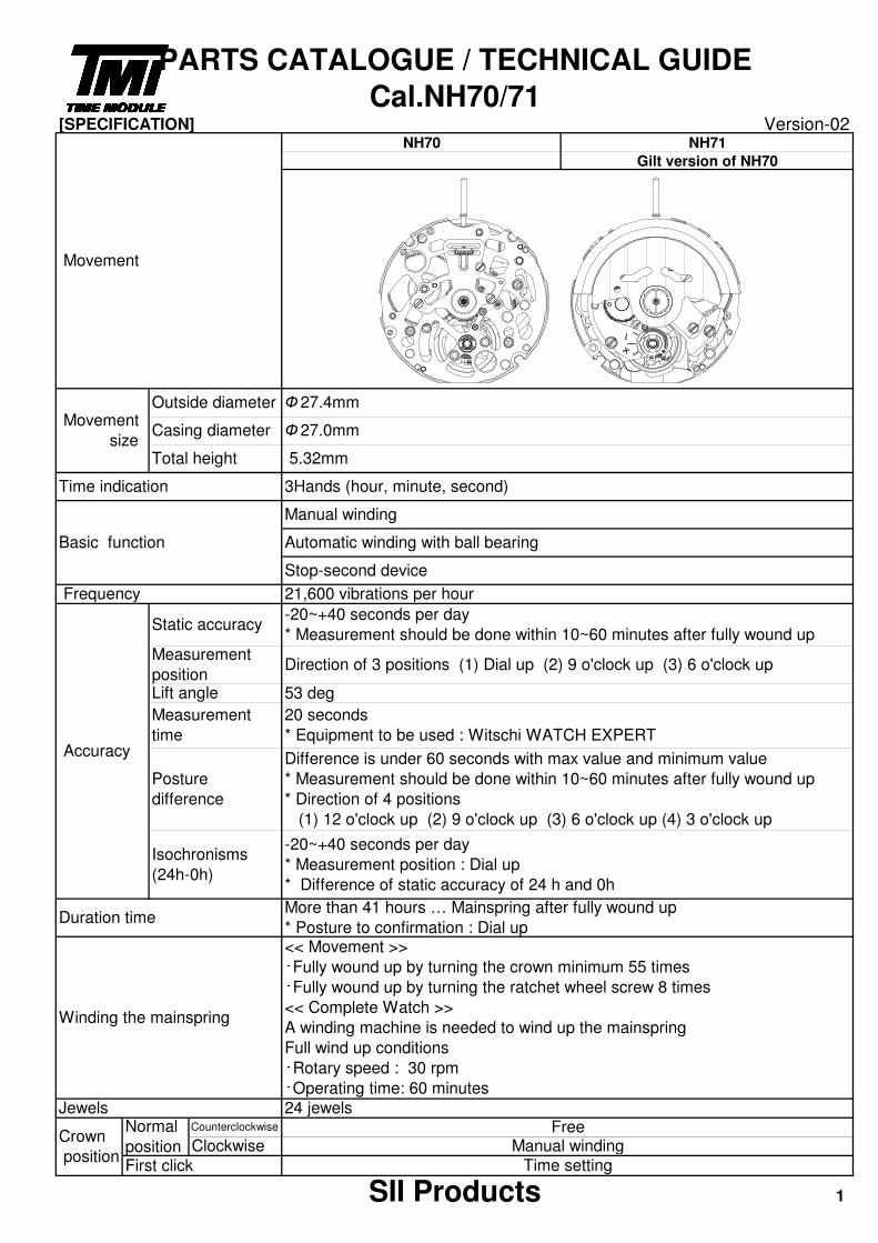
[SPECIFICATION] Version-02
SII Products 1
Time indication 3Hands (hour, minute, second)
Stop-second device
First click Time setting
Basic function
Crown
position
Normal
position
Counterclockwise FreeClockwise Manual winding
Duration timeMore than 41 hours … Mainspring after fully wound up
* Posture to confirmation : Dial up
Winding the mainspring
<< Movement >>・Fully wound up by turning the crown minimum 55 times・Fully wound up by turning the ratchet wheel screw 8 times
<< Complete Watch >>
A winding machine is needed to wind up the mainspring
Full wind up conditions・Rotary speed : 30 rpm・Operating time: 60 minutes
Jewels 24 jewels
Frequency 21,600 vibrations per hour
Accuracy
Static accuracy-20~+40 seconds per day
* Measurement should be done within 10~60 minutes after fully wound up
Measurement
positionDirection of 3 positions (1) Dial up (2) 9 o'clock up (3) 6 o'clock up
Lift angle 53 deg
Measurement
time
20 seconds
* Equipment to be used : Witschi WATCH EXPERT
Posture
difference
Difference is under 60 seconds with max value and minimum value
* Measurement should be done within 10~60 minutes after fully wound up
* Direction of 4 positions
(1) 12 o'clock up (2) 9 o'clock up (3) 6 o'clock up (4) 3 o'clock up
Isochronisms
(24h-0h)
-20~+40 seconds per day
* Measurement position : Dial up
* Difference of static accuracy of 24 h and 0h
Manual winding
Automatic winding with ball bearing
PARTS CATALOGUE / TECHNICAL GUIDE
Cal.NH70/71
Movement
Movement
size
Outside diameter Ф 27.4mm
Casing diameter Ф 27.0mm
Total height 5.32mm
NH70 NH71---- Gilt version of NH70
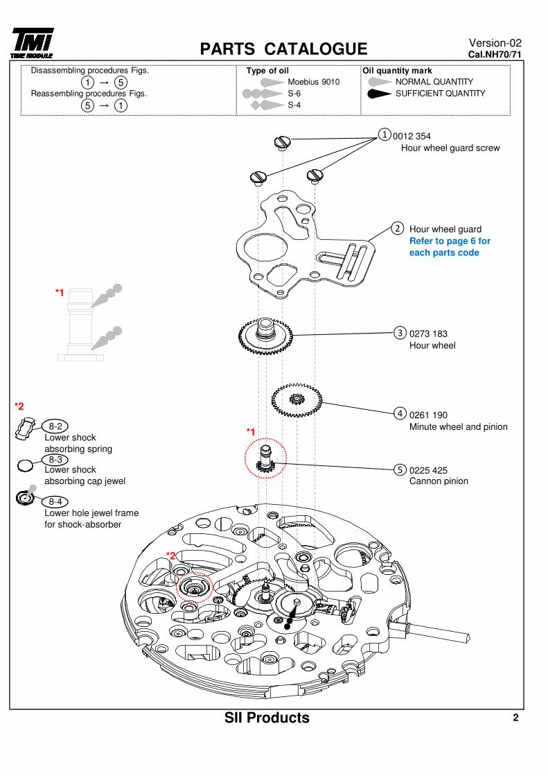
0012 354
Hour wheel guard screw
Hour wheel guard
Refer to page 6 for
each parts code
0273 183
Hour wheel
0261 190
Minute wheel and pinion
0225 425Cannon pinion
Lower hole jewel frame
for shock-absorber
SII Products 2
8-4
Lower shock
absorbing cap jewel
PARTS CATALOGUEVersion-02Cal.NH70/71
8-2
8-3
Lower shock
absorbing spring
*1
1
2
3
4
5
Type of oil Oil quantity mark
Moebius 9010 NORMAL QUANTITY
S-6 SUFFICIENT QUANTITY
S-4
Disassembling procedures Figs.
1 → 5Reassembling procedures Figs.
5 → 1
*2
*1
*2
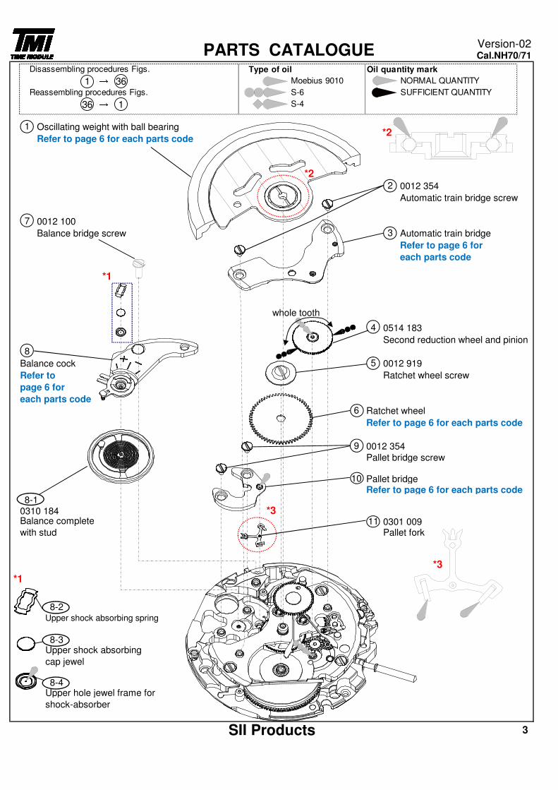
Oscillating weight with ball bearing
Refer to page 6 for each parts code
0012 354
Automatic train bridge screw
0012 100
Balance bridge screw Automatic train bridge
Refer to page 6 for
each parts code
0514 183
Second reduction wheel and pinion
Balance cock 0012 919
Refer to Ratchet wheel screw
page 6 for
each parts code
Ratchet wheel
Refer to page 6 for each parts code
0012 354
Pallet bridge screw
Pallet bridgeRefer to page 6 for each parts code
0310 1840301 009Pallet fork
3
Upper shock absorbing spring
8-3Upper shock absorbing
cap jewel
8-4
3
Upper hole jewel frame for
shock-absorber
SII Products
10
8
5
6
8-1
4
Balance complete
with stud11
8-2
9
7
PARTS CATALOGUEVersion-02Cal.NH70/71
1
2
*3
Type of oil Oil quantity mark
Moebius 9010 NORMAL QUANTITY
S-6 SUFFICIENT QUANTITY
S-436 → 1
Disassembling procedures Figs.
1 → 36Reassembling procedures Figs.
*1
*1
*2
*2
*3
whole tooth
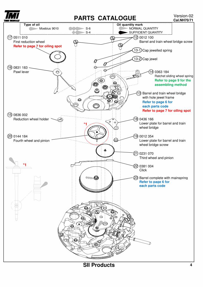
0511 010 0012 100
First reduction wheel
Refer to page 7 for oiling spot
Cap jewelled spring
Cap jewel
0831 183
Pawl lever 0363 184
Refer to page 6 for
each parts code
Refer to page 7 for oiling spot
0836 002
Reduction wheel holder 0436 166
0144 184 0012 354
Fourth wheel and pinion
0231 070
Third wheel and pinion
0381 004Click
Barrel complete with mainspringRefer to page 6 foreach parts code
4
Lower plate for barrel and train
wheel bridge screw
21
22
23
SII Products
15
18
Lower plate for barrel and train
wheel bridge
20 19
13
PARTS CATALOGUEVersion-02Cal.NH70/71
17 12
Barrel and train wheel bridge screw
13-1
13-2
16
14
Ratchet sliding wheel spring
Refer to page 9 for the
assembling method
Barrel and train wheel bridge
with hole jewel frame
Type of oil Oil quantity mark
Moebius 9010 S-6 NORMAL QUANTITY
S-4 SUFFICIENT QUANTITY
*1
*1
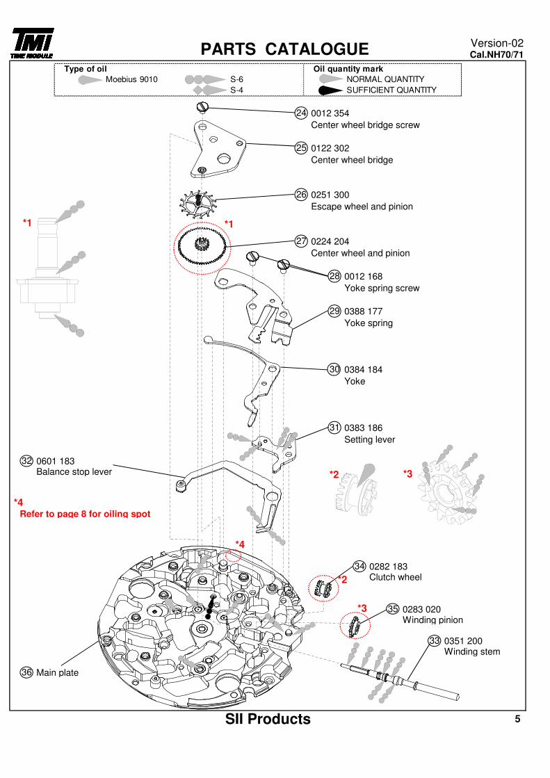
0012 354
Center wheel bridge screw
0122 302
Center wheel bridge
0251 300
Escape wheel and pinion
0224 204
Center wheel and pinion
0012 168
Yoke spring screw
0388 177
Yoke spring
0384 184
Yoke
0383 186
Setting lever
0601 183Balance stop lever
Refer to page 8 for oiling spot
0282 183Clutch wheel
0283 020Winding pinion
0351 200Winding stem
Main plate36
SII Products 5
33
35
34
32
PARTS CATALOGUEVersion-02Cal.NH70/71
24
25
26
27
28
29
30
31
Type of oil Oil quantity mark
Moebius 9010 S-6 NORMAL QUANTITY
S-4 SUFFICIENT QUANTITY
*1
*2 *3
*4
*2
*3
*4
*1
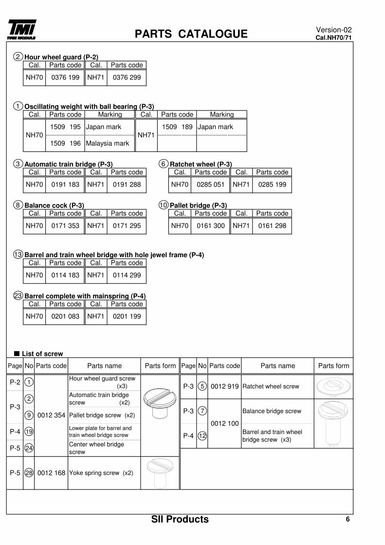
Hour wheel guard (P-2)
Oscillating weight with ball bearing (P-3)
Automatic train bridge (P-3) Ratchet wheel (P-3)
Balance cock (P-3) Pallet bridge (P-3)
Barrel and train wheel bridge with hole jewel frame (P-4)
Barrel complete with mainspring (P-4)
■■■■ List of screw
Parts code
PARTS CATALOGUEVersion-02Cal.NH70/71
SII Products 6
1509 196 Malaysia mark
PageParts form Parts form
0012 354
P-2 1Hour wheel guard screw
(x3)
Automatic train bridge
screw (x2)
NH70 0376 199 NH71 0376 299
2
Cal. Parts code Cal.
No Parts code
1
Page No Parts code Parts name
1509 195 Japan mark
Parts code Marking
P-3
2
Parts name
5 0012 919
9 Pallet bridge screw (x2)P-3 7
0012 100
Balance bridge screw
24Center wheel bridge
screw
P-4 12Barrel and train wheel
bridge screw (x3)
Ratchet wheel screwP-3
P-4 19Lower plate for barrel and
train wheel bridge screw
P-5
P-5 28 0012 168 Yoke spring screw (x2)
Marking
NH71
1509 189 Japan mark
Cal.
NH70
Cal. Parts code
NH70 0285 051 NH71
13
23
Cal. Parts code Cal. Parts code
0285 199
8 10
6
Cal. Parts code Cal. Parts codeParts code
NH70 0191 183 NH71 0191 288
3
Cal. Parts code Cal.
Parts code
NH70 0161 300 NH71 0161 298
Cal. Parts code Cal. Parts code
NH70 0171 353 NH71 0171 295
Cal. Parts code Cal.
Cal. Parts code Cal. Parts code
NH70 0114 183 NH71 0114 299
NH70 0201 083 NH71 0201 199
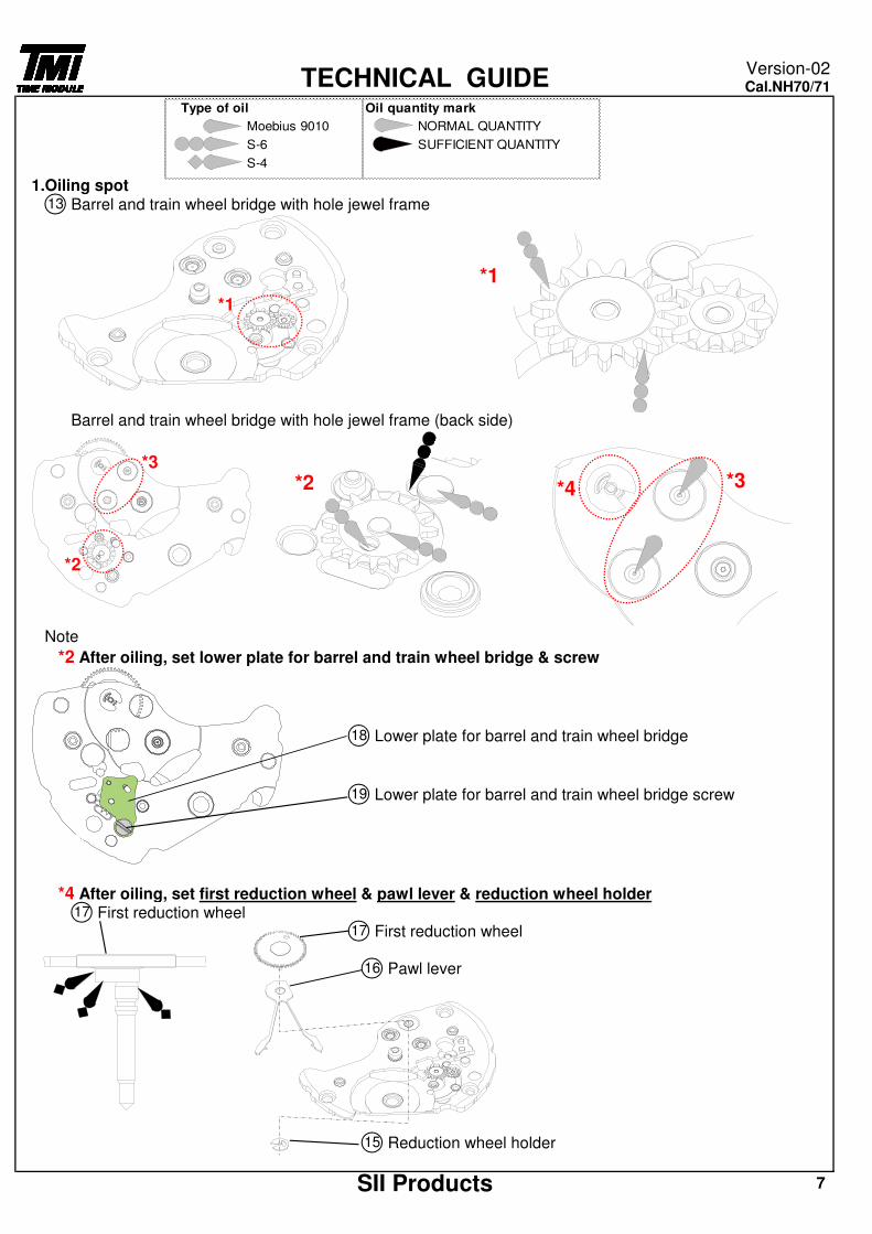
1.Oiling spotBarrel and train wheel bridge with hole jewel frame
Barrel and train wheel bridge with hole jewel frame (back side)
Note
*2 After oiling, set lower plate for barrel and train wheel bridge & screw
Lower plate for barrel and train wheel bridge
Lower plate for barrel and train wheel bridge screw
*4 After oiling, set first reduction wheel & pawl lever & reduction wheel holderFirst reduction wheel
First reduction wheel
Pawl lever
Reduction wheel holder
7
TECHNICAL GUIDEVersion-02Cal.NH70/71
13
18
19
17
17
16
15
SII Products
Type of oil Oil quantity mark
Moebius 9010 NORMAL QUANTITY
S-6 SUFFICIENT QUANTITY
S-4
*2
*3
*1
*1
*2 *3*4
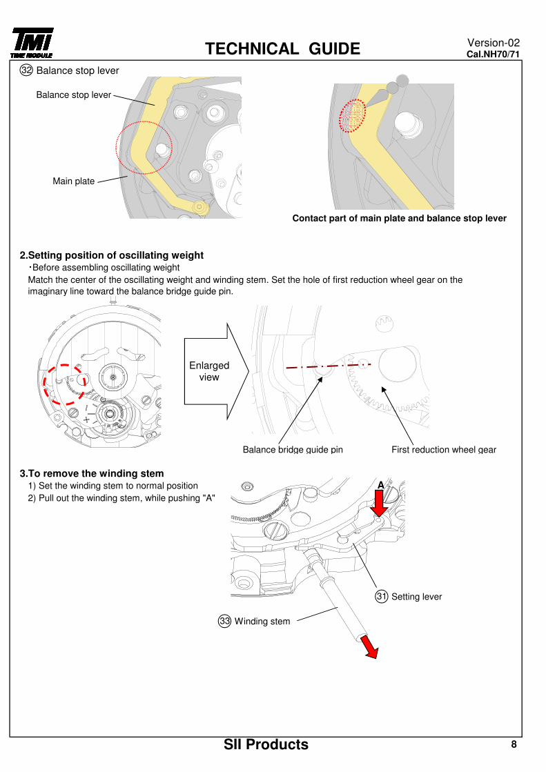
Balance stop lever
Balance stop lever
Main plate
Contact part of main plate and balance stop lever
2.Setting position of oscillating weight・Before assembling oscillating weight
Match the center of the oscillating weight and winding stem. Set the hole of first reduction wheel gear on the
imaginary line toward the balance bridge guide pin.
Balance bridge guide pin First reduction wheel gear
3.To remove the winding stem1) Set the winding stem to normal position
2) Pull out the winding stem, while pushing "A"
Setting lever
Winding stem
SII Products 8
TECHNICAL GUIDEVersion-02Cal.NH70/71
32
31
33
Enlarged view
A
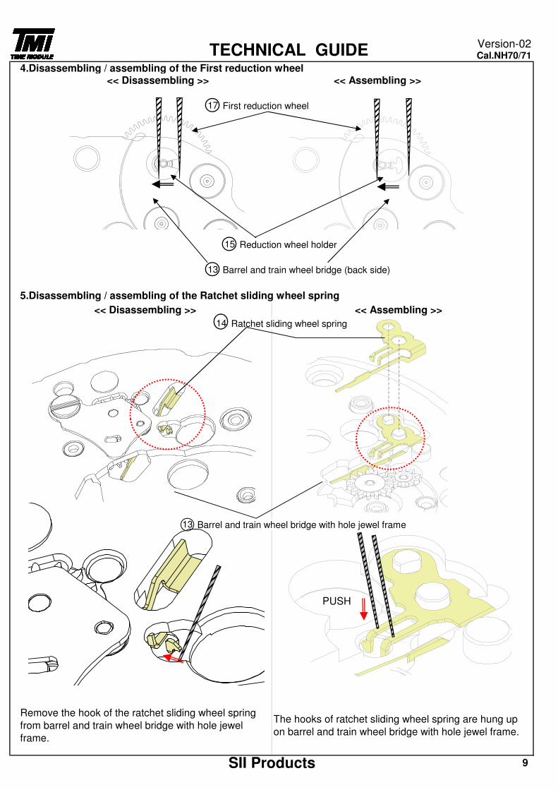
4.Disassembling / assembling of the First reduction wheel
First reduction wheel
Reduction wheel holder
Barrel and train wheel bridge (back side)
5.Disassembling / assembling of the Ratchet sliding wheel spring
Ratchet sliding wheel spring
Barrel and train wheel bridge with hole jewel frame
Remove the hook of the ratchet sliding wheel spring
from barrel and train wheel bridge with hole jewel
frame.
The hooks of ratchet sliding wheel spring are hung up
on barrel and train wheel bridge with hole jewel frame.
SII Products 9
15
13
<< Disassembling >> << Assembling >>
14
13
17
TECHNICAL GUIDEVersion-02Cal.NH70/71
<< Disassembling >> << Assembling >>
PUSH
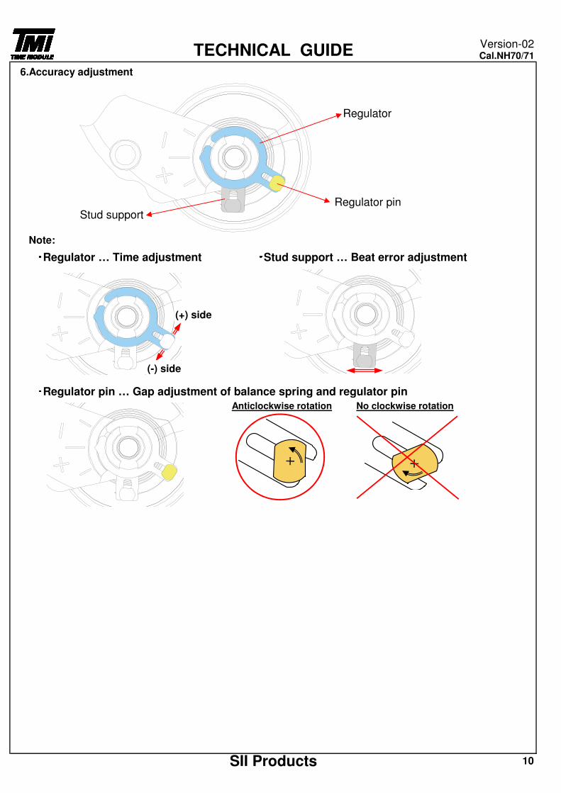
6.Accuracy adjustment
Regulator
Regulator pinStud support
Note:・・・・Regulator … Time adjustment ・・・・Stud support … Beat error adjustment
・・・・Regulator pin … Gap adjustment of balance spring and regulator pin
SII Products 10
TECHNICAL GUIDEVersion-02Cal.NH70/71
Anticlockwise rotation No clockwise rotation
(+) side
(-) side

7.To wind up the mainspring<<Movement>>
Screwdriver winding … Turn the ratchet wheel screw 8 times clockwise.
Screwdriver
Ratchet wheel screw
Ratchet wheel
8.How to attach handsPlace the movement directly on a flat metal plate or something similar to attach the hands.
We recommend the use of movement holder to attach hands. Static weighting
For hands attachment, please use a special equipment.
When the movement receives a strong shock, it may be damaged.
9.Accuracy measurement conditionStatic Accuracy : -20~+40 seconds per day
Measurement Conditions1) Measurement should be done within 10~60 minutes after fully wound up2) Lift angle : 53 deg3) Measurement position : (1) Dial up (2) 9 o'clock up (3) 6 o'clock up4) Minimum measurement Time : 20 seconds5) Stabilizing Time :
Leave the watch for at least 20 seconds to stabilize after you change its measurement position.
SII Products 11
TECHNICAL GUIDEVersion-02Cal.NH70/71
The mainspring would be fully wound up by turning the ratchet wheel screw 8 times clockwise. (Manual winding or Screwdriver)
Manual winding … Rotate crown clockwise at normal position by minimum 55 times. (Equal to ratchet wheel screw 8 times )
[ Manual winding ] [ Screwdriver winding ]
Metal plate
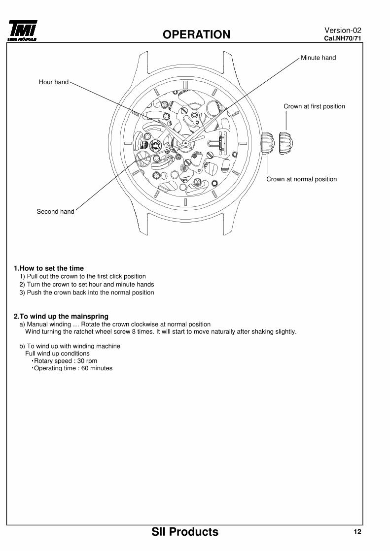
Minute hand
Hour hand
Crown at first position
Crown at normal position
Second hand
1.How to set the time1) Pull out the crown to the first click position
2) Turn the crown to set hour and minute hands
3) Push the crown back into the normal position
2.To wind up the mainspringa) Manual winding … Rotate the crown clockwise at normal position
Wind turning the ratchet wheel screw 8 times. It will start to move naturally after shaking slightly.
b) To wind up with winding machineFull wind up conditions・Rotary speed : 30 rpm・Operating time : 60 minutes
SII Products 12
OPERATIONVersion-02Cal.NH70/71