Embed Size (px)
Citation preview
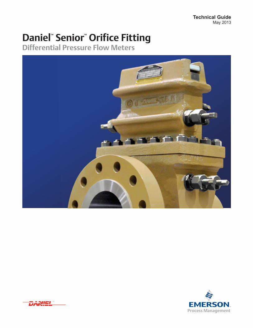
Technical GuideMay 2013
Daniel™ Senior™ Orifice Fitting Differential Pressure Flow Meters


1www.EmersonProcess.com
Technical GuideDifferential Pressure Flow Meters
Overview The Daniel Senior Orifice Fitting is a dual-chamber device that reigns as the most widely used means of measurement for natural gas. With an installed base of well over one million orifice fittings worldwide, more natural gas is measured with The Daniel Senior Orifice Fitting than any other type of device.
The Senior Orifice Fitting (Figure 1) saves users time and money by providing a fast, safe and extremely simple method of changing orifice plates under pressure without flow interruption, preventing unscheduled shutdowns. In addition, its dual-chamber design eliminates the need for costly piping bypasses or additional valves and fittings required with conventional orifice flange installations.
The Senior Orifice Fitting meets all requirements and recommendations for accurate flow measurement of gas and liquid, including AGA-3 / API 14.3 requirements, without compromise.
From duplex stainless steel fittings to carbon steel and severe service trims (Monel, Hastellloy-C and Alloy-20), Daniel delivers fittings to meet the stringent requirements of corrosive environments or specific temperature and pressure needs.
The Senior Orifice Fitting requires no beta ratio range restrictions and no added uncertainty to published values. It is available in 2" through 48" flange line sizes, up to ANSI 2500, and 10,000 psi (68958 kPa) in 3" to 6" only.
Proving its worth every day
(1) Please consult Daniel factory for severe service and other code requirements, including low -temp, high H2S, high CO2, and special applications.
(2) Hard-seat using injected grease / sealant is recommended for production applications where sand, grit and other particulate matter is present.
(3) Soft-seat, greaseless seal is not recommended / intended for production applications where sand, grit and other particulate matter is commonly present (e.g., shale gas production).
Typical Applications � Gas transmission / pipeline
� Gas distribution
� Offshore gas production and onshore, including shale
� Gas plants
� Floating Production, Storage and Offloading (FPSO)
� CO2 injection
� Bi-directional high pressure storage
Features and Benefits � Highly reliable, time proven technology
� Field-repairable, reducing downtime and costs associated with shipping to a repair site
� Available in compliance with ISO-5167, PED, NORSOK and other code standards / requirements (1)
� Corrosion resistant and other special casting materials, including Wrought Carbon Steel (WCC, WCB), Low Temperature Carbon Steel (LCC), 316 Stainless Steel and Duplex, makes this fitting suitable for sour gas service and other special applications
� Slide valve / isolation mechanism featuring a metal-to-metal seat (hard seat(2)) with injected lubricant / sealant is standard on all Daniel Senior Orifice Fittings, providing an optimal seal in the production environment where particulate matter is common
� Optional soft seat slide valve(3) (O-ring seal without lubricant) is available in 2" to 12" sizes, up to 600 ANSI, for use with gas products such as ethylene
Figure 1: Daniel Senior Orifice Fitting

2 www.EmersonProcess.com
May 2013Senior Orifice Fitting
A. Under flow conditions B. Equalize pressure 1. Open equalizer valve
Operational Sequence of Removing an Orifice Plate Under Pressure(1)
D. Bleed upper chamber and lubricate valve seat 4. Close slide valve carrier (isolation mechanism) 5. Close equalizer valve and inject sealant 6. Open bleeder valve (blow-down valve)
C. Raise orifice plate 2. Open slide valve carrier (isolation mechanism) 3. Raise plate to upper chamber
(1) CAUTION: This operational sequence is representational only and is not intended for use as a field guide to operations. NOTICE: See operation manual and always read and follow the detailed operating instructions provided with each fitting before attempting to operate.
3www.EmersonProcess.com
Technical GuideDifferential Pressure Flow Meters
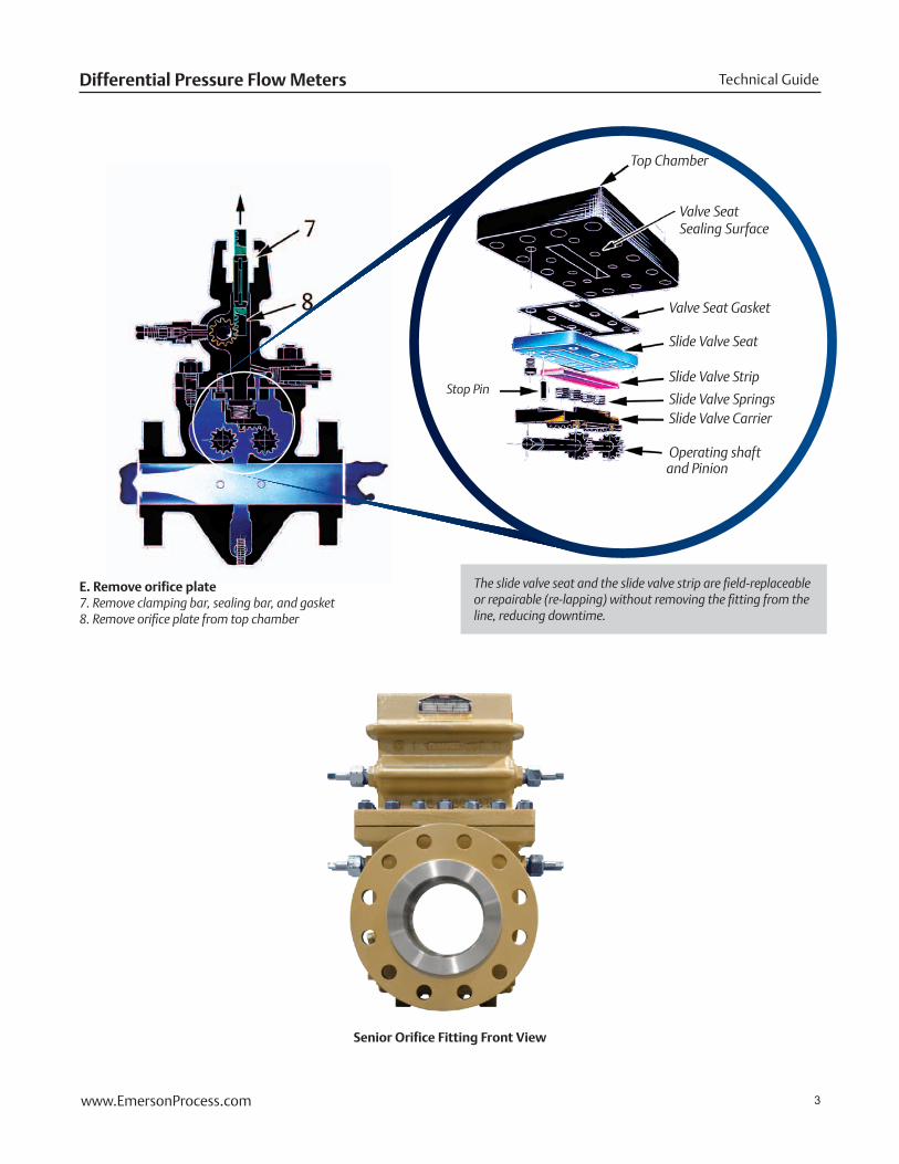
The slide valve seat and the slide valve strip are field-replaceable or repairable (re-lapping) without removing the fitting from the line, reducing downtime.
E. Remove orifice plate7. Remove clamping bar, sealing bar, and gasket8. Remove orifice plate from top chamber
Stop Pin
Valve Seat Gasket
Slide Valve Seat
Slide Valve Strip
Slide Valve SpringsSlide Valve Carrier
Operating shaft and Pinion
Senior Orifice Fitting Front View
Valve Seat Sealing Surface
Top Chamber

4 www.EmersonProcess.com
May 2013Senior Orifice Fitting
Standard Specifications(1)
(1) Please consult Daniel if your requirements are outside the specifications. Other product and material offerings may be available depending on the application.
(2) Orifice Plate Seal used may limit the service temperatures and special trims will be required for high temperature applications. Maximum temperature is contingent on limited pressure. Please consult factory.
Indicator PlatesStandard on all Senior Orifice Fittings, the indicator plate clearly shows the direction of the open and closed position of the slide valve.
Operating WrenchAn operating wrench is provided with each fitting for safe operation of the shaft and pinions, equalizer valve, grease gun, bleeder valve and clamping bar screws.
Hydrostatic Testing All Daniel Senior Orifice Fittings are hydrostatically tested to 1.5 times operating pressure.
Trim � NACE Trim (MR-0175-2002) 2" to 8" 150 to 600 ANSI
RFFN Fittings (Standard)
� A-trim 10" + and all ANSI classes 900+ (Standard)
� Other optional trims available for severe service and other code requirements (High H2S, High CO2, NORSOK, Daniel “AASG” and special applications)
Senior Orifice Fitting - FlangnekTM ConfigurationSenior Orifice Fitting - Flanged Configuration
Differential Pressure Taps Internal Tap Hole Sizes
� In accordance with API 14.3 (AGA Report #3)
� In accordance with ISO-5167 (option)
1/2" NPT Process Connection (Standard)
� In accordance with API 14.3 (standard for all)
� Flanged differential taps (option)
Telemetering Taps
� Standard on all 2 to 12 inch 600 ANSI
� Available on all other sizes and ANSI classes
Line Bore Tolerances � 2" and 3" sizes, ± .003"
� 4", 6", 8", 10" sizes, ± .004"
� 12" and 16", ± .005"
Operating Shafts � Stainless Steel, double-ended (standard)
▪ Eliminates the need to reverse shafts in the field
Application TemperatureMaximum Temperatures(2)
� 150 to 900 ANSI, -20°F to +450°F(2) (-29°C to 232°C)
� 1500 and 2500 ANSI, -20°F to +275°F (2) (-29°C to 135°C)
5www.EmersonProcess.com
Technical GuideDifferential Pressure Flow Meters
(1) NOTE: Body / Top Gasket peroxide-cured Nitrile O-ring for ANSI 1500 Orifice Fittings. Male and female gasket joint with ParkerTM seal gaskets for ANSI 2500 Orifice Fitting.
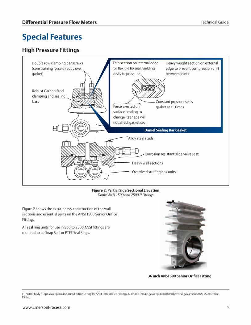
Figure 2 shows the extra-heavy construction of the wall sections and essential parts on the ANSI 1500 Senior Orifice Fitting.
All seal ring units for use in 900 to 2500 ANSI fittings are required to be Snap Seal or PTFE Seal Rings.
Thin section on internal edge for flexible lip seal, yielding easily to pressure
Heavy weight section on external edge to prevent compression drift between joints
Force exerted on surface tending to change its shape will not affect gasket seal
Constant pressure seals gasket at all times
Alloy steel studs
Corrosion resistant slide valve seat
Heavy wall sections
Oversized stuffing box units
Double row clamping bar screws (constraining force directly over gasket)
Robust Carbon Steel clamping and sealing bars
Figure 2: Partial Side Sectional ElevationDaniel ANSI 1500 and 2500(1) Fittings
Special Features
36 inch ANSI 600 Senior Orifice Fitting
High Pressure Fittings
Daniel Sealing Bar Gasket

6 www.EmersonProcess.com
May 2013Senior Orifice Fitting
Meter Tube Flange Fitting Flange
Daniel 400 and Higher ANSIDaniel 125 to 300 ANSI
Figure 3: Method of Aligning Meter Tube Flange to Orifice Fitting Flange
(1) CAUTION: This view is representational only and is not intended for use as a field guide to operations. NOTICE: See operation manual and always read and follow the detailed operating instructions provided with each fitting before attempting to operate.
(2) Slide valve / Isolation mechanism does not comply with or adhere to API 598 valve criteria. Hard seat (using sealant / lubricant) is standard on all Daniel Senior Orifice Fittings.Soft seat (O-ring seal using no grease) is available in size 2" to 12" up to 600 ANSI. Not intended for production applications.
In Daniel Senior Orifice Fittings, the slide valve seat (Part No. 18) is part of the upper chamber. The slide valve strip (Part No.3) moves underneath this seat, thereby utilizing line pressure to affect a positive seal. The slide valve strip is maintained in the “floating” position by minimum spring pressure.
Before the slide valve (Figure 4) is opened, sealant (lubricant)is injected using the grease gun (Part No. 23). Pressure is
Top Chamber
Continuous Grease Groove (Encircle Valve Opening)
Equalizer Valve (part No. 1)
Equalizer Passageways
Slide Valve Strip (Part No. 3)
Lower CompartmentClearance pad prevents slide valve from being closed until plate carrier is fully centered in the line.
Slide Valve Carrier (Part No. 17)
Slide Valve Seat (Part No. 18)
Grease Gun (Part No. 23)
Figure 4: Slide Valve / Isolation Mechanism(2)
Alignment of Meter Tube Flange to Orifice Fitting Flange
On all sizes, 300 ANSI or under, three dowel pin flange-alignment holes are drilled in the flanges.
On Daniel 400 ANSI fittings or higher, flanges are manufactured with close-tolerance, square-shouldered, large male flange-facing on fitting, and large female flange-facing on meter tube to assure proper internal alignment.
Flange gaskets are precision-cut so they will not, under compression, extend into the internal bore of fitting. Refer to Figure 3.
Slide Valve(1)
then equalized throughout the entire fitting by operation of the equalizer valve (Part No. 1). Equalized pressure on both sides of the slide valve strip allows slide valve to move freely without wear. The metal-to-metal hard seat seal (with injected sealant / lubricant) provides an optimal and reliable seal in the production environment where sand and particulate matter are common.
7www.EmersonProcess.com
Technical GuideDifferential Pressure Flow Meters
Plate AlignmentThe plate carriers in all 2" to 8" Senior Orifice Fittings are centered using a fixed three-point positioning system. This assures orifice plate concentricity in accordance with current API 14.3 (AGA Report #3) tolerances while the fitting is positioned in the vertical and horizontal planes.
The Senior Orifice Fitting is composed of two independent compartments separated by a hardened stainless steel slide valve.
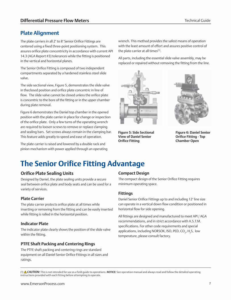
The side sectional view, Figure 5, demonstrates the slide valve in theclosed position and orifice plate concentric in line of flow. The slide valve cannot be closed unless the orifice plate is concentric to the bore of the fitting or in the upper chamber during plate removal.
Figure 6 demonstrates the Daniel top chamber in the opened position with the plate carrier in place for change or inspection of the orifice plate. Only a few turns of the operating wrench are required to loosen screws to remove or replace clamping and sealing bars. Set screws always remain in the clamping bar. This feature adds greatly to speed and ease of operation.
The plate carrier is raised and lowered by a double rack and pinion mechanism with power applied through an operating
wrench. This method provides the safest means of operation with the least amount of effort and assures positive control of the plate carrier at all times(1).
All parts, including the essential slide valve assembly, may be replaced or repaired without removing the fitting from the line.
Orifice Plate Sealing UnitsDesigned by Daniel, the plate sealing units provide a secure seal between orifice plate and body seats and can be used for a variety of services.
Plate Carrier The plate carrier protects orifice plate at all times while inserting or removing from the fitting and can be easily inserted while fitting is rolled in the horizontal position.
Indicator PlateThe indicator plate clearly shows the position of the slide valve within the fitting.
PTFE Shaft Packing and Centering RingsThe PTFE shaft packing and centering rings are standard equipment on all Daniel Senior Orifice Fittings in all sizes and ratings.
Compact DesignThe compact design of the Senior Orifice Fitting requires minimum operating space.
FittingsDaniel Senior Orifice Fittings up to and including 12" line size can operate in a vertical down flow condition or positioned in horizontal flow for side opening.
All fittings are designed and manufactured to meet API / AGA recommendations, and in strict accordance with A.S.T.M. specifications. For other code requirements and special applications, including NORSOK, ISO, PED, CO2, H2S, low temperature, please consult factory.
The Senior Orifice Fitting Advantage
(1) CAUTION: This is not intended for use as a field guide to operations. NOTICE: See operation manual and always read and follow the detailed operating instructions provided with each fitting before attempting to operate.
Figure 5: Side Sectional View of Daniel Senior Orifice Fitting
Figure 6: Daniel Senior Orifice Fitting - Top Chamber Open
8 www.EmersonProcess.com
May 2013Senior Orifice Fitting
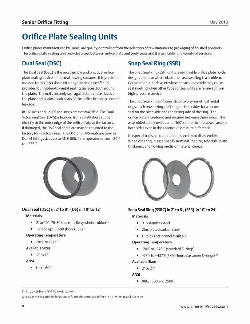
Orifice Plate Sealing UnitsOrifice plates manufactured by Daniel are quality-controlled from the selection of raw materials to packaging of finished products. The orifice plate sealing unit provides a seal between orifice plate and body seats and it is available for a variety of services.
Dual Seal (DSC) The Dual Seal (DSC) is the most simple and practical orifice plate sealing device for normal flowing streams. It is precision molded from 70-80 shore nitrile synthetic rubber(1) and provides four rubber-to-metal sealing surfaces 360° around the plate. The units securely seal against both outer faces of the plate and against both seats of the orifice fitting to prevent leakage.
In 16" sizes and up, DS seal rings are not available. The Dual Vulcanized Seal (DVS) is bonded from 80-90 shore rubber directly to the outer edge of the orifice plate at the factory. If damaged, the DVS seal and plate may be returned to the factory for revulcanizing. The DSC and DVS seals are used in Daniel fittings sizes up to ANSI 600, in temperatures from -20°F to +275°F.
Snap Seal Ring (SSR)The Snap Seal Ring (SSR) unit is a removable orifice plate holder designed for use where elastomer seal swelling is a problem. Certain media, such as ethylene or carbon dioxide may cause seal swelling when other types of seal units are removed from high-pressure service.
The Snap Seal Ring unit consists of two symmetrical metal rings, each one having an O-ring on both sides for a secure seal on the plate side and the fitting side of the ring. The orifice plate is centered and secured between these rings. The assembled unit provides a full 360° rubber-to-metal seal around both sides even in the absence of pressure differential.
No special tools are required for assembly or disassembly. When ordering, please specify nominal line size, schedule, plate thickness, and flowing media or material choice.
Snap Seal Ring (SSRC) in 2" to 8", (SSR) in 10" to 24"
Materials
� 316 stainless steel
� Zinc-plated carbon steel
� Duplex and Inconel available
Operating Temperature
� -20°F to +275°F (standard O-rings)
� -67°F to +437°F (FKM Fluoroelastomer O-rings)(2)
Available Sizes
� 2" to 24"
ANSI
� 900, 1500 and 2500
Dual Seal (DSC) in 2" to 8", (DS) in 10" to 12"
Materials
� 2" to 10": 70-80 shore nitrile synthetic rubber(1)
� 12" and up: 80-90 shore rubber
Operating Temperature
� -20°F to +275°F
Available Sizes
� 2" to 12"
ANSI
� Up to 600
(1) Also available in FKM Fluoroelastomor.
(2) FKM is the designation for a class of fluoroelastomers as defined in ASTM D1418 and ISO 1629.
9www.EmersonProcess.com
Technical GuideDifferential Pressure Flow Meters
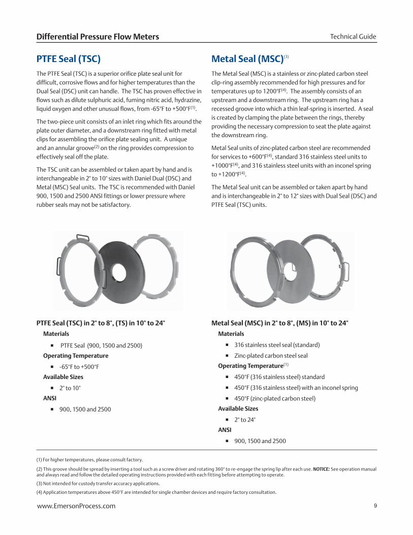
PTFE Seal (TSC)The PTFE Seal (TSC) is a superior orifice plate seal unit for difficult, corrosive flows and for higher temperatures than the Dual Seal (DSC) unit can handle. The TSC has proven effective in flows such as dilute sulphuric acid, fuming nitric acid, hydrazine, liquid oxygen and other unusual flows, from -65°F to +500°F(1).
The two-piece unit consists of an inlet ring which fits around the plate outer diameter, and a downstream ring fitted with metal clips for assembling the orifice plate sealing unit. A unique and an annular groove(2) on the ring provides compression to effectively seal off the plate.
The TSC unit can be assembled or taken apart by hand and is interchangeable in 2" to 10" sizes with Daniel Dual (DSC) and Metal (MSC) Seal units. The TSC is recommended with Daniel 900, 1500 and 2500 ANSI fittings or lower pressure where rubber seals may not be satisfactory.
Metal Seal (MSC)(3)
The Metal Seal (MSC) is a stainless or zinc-plated carbon steel clip-ring assembly recommended for high pressures and for temperatures up to 1200°F(4). The assembly consists of an upstream and a downstream ring. The upstream ring has a recessed groove into which a thin leaf-spring is inserted. A seal is created by clamping the plate between the rings, thereby providing the necessary compression to seat the plate against the downstream ring.
Metal Seal units of zinc-plated carbon steel are recommended for services to +600°F(4), standard 316 stainless steel units to +1000°F(4), and 316 stainless steel units with an inconel spring to +1200°F(4).
The Metal Seal unit can be assembled or taken apart by hand and is interchangeable in 2" to 12" sizes with Dual Seal (DSC) and PTFE Seal (TSC) units.
PTFE Seal (TSC) in 2" to 8", (TS) in 10" to 24"
Materials
� PTFE Seal (900, 1500 and 2500)
Operating Temperature
� -65°F to +500°F
Available Sizes
� 2" to 10"
ANSI
� 900, 1500 and 2500
Metal Seal (MSC) in 2" to 8", (MS) in 10" to 24"
Materials
� 316 stainless steel seal (standard)
� Zinc-plated carbon steel seal
Operating Temperature(1)
� 450°F (316 stainless steel) standard
� 450°F (316 stainless steel) with an inconel spring
� 450°F (zinc-plated carbon steel)
Available Sizes
� 2" to 24"
ANSI
� 900, 1500 and 2500
(1) For higher temperatures, please consult factory.
(2) This groove should be spread by inserting a tool such as a screw driver and rotating 360° to re-engage the spring lip after each use. NOTICE: See operation manual and always read and follow the detailed operating instructions provided with each fitting before attempting to operate.
(3) Not intended for custody transfer accuracy applications.
(4) Application temperatures above 450°F are intended for single chamber devices and require factory consultation.
10 www.EmersonProcess.com
May 2013Senior Orifice Fitting
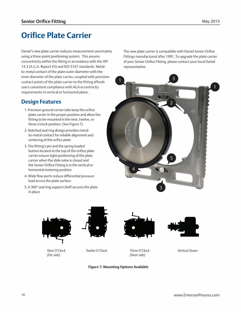
Daniel’s new plate carrier reduces measurement uncertainty using a three-point positioning system. This assures concentricity within the fitting in accordance with the API 14.3 (A.G.A. Report #3) and ISO-5167 standards. Metal-to-metal contact of the plate outer diameter with the inner diameter of the plate carrier, coupled with precision contact points of the plate carrier to the fitting affords users consistent compliance with AGA eccentricity requirements in vertical or horizontal plane.
Design Features1. Precision ground corner tabs keep the orifice
plate carrier in the proper position and allow the fitting to be mounted in the nine, twelve, or three o’clock position. (See Figure 7)
2. Notched seal ring design provides metal-to-metal contact for reliable alignment and centering of the orifice plate
3. The fitting’s pin and the spring loaded button located at the top of the orifice plate carrier ensure tight positioning of the plate carrier when the slide valve is closed and the Senior Orifice Fitting is in the vertical or horizontal metering position
4. Wide flow ports reduce differential pressure load across the plate surface
5. A 360° seal ring support shelf secures the plate in place
Orifice Plate Carrier
The new plate carrier is compatible with Daniel Senior Orifice Fittings manufactured after 1991. To upgrade the plate carrier of your Senior Orifice Fitting, please contact your local Daniel representative.
3
5
2
4
1
31
Figure 7: Mounting Options Available
Nine O’Clock(Far side)
Twelve O’Clock Three O’Clock(Near side)
Vertical Down
11www.EmersonProcess.com
Technical GuideDifferential Pressure Flow Meters
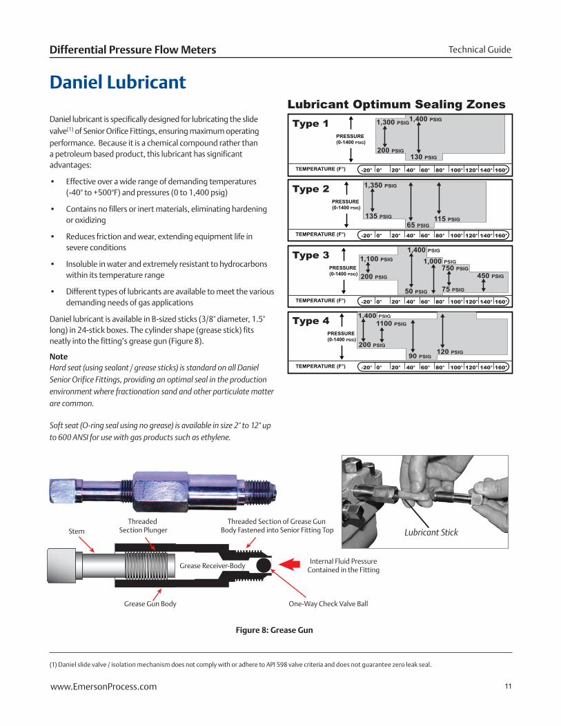
Daniel Lubricant
TEMPERATURE (F°)
1,300 PSIG
200 PSIG
1,400 PSIG
130 PSIG
0°-20° 40° 60° 80° 100° 120° 140° 160°20°
PRESSURE (0-1400 PSIG)
Type 1
TEMPERATURE (F°) 0°-20° 40° 60° 80° 100° 120° 140° 160°20°
PRESSURE (0-1400 PSIG)
Type 2 1,350 PSIG
135 PSIG
65 PSIG115 PSIG
TEMPERATURE (F°) 0°-20° 40° 60° 80° 100° 120° 140° 160°20°
PRESSURE (0-1400 PSIG)
Type 3 1,100 PSIG 1,000 PSIG750 PSIG
200 PSIG
1,400 PSIG
50 PSIG 75 PSIG
450 PSIG
TEMPERATURE (F°) 0°-20° 40° 60° 80° 100° 120° 140° 160°20°
PRESSURE (0-1400 PSIG)
Type 4 1100 PSIG
200 PSIG
1,400 PSIG
90 PSIG120 PSIG
Lubricant Optimum Sealing Zones
Lubricant Stick
Daniel lubricant is specifically designed for lubricating the slide valve(1) of Senior Orifice Fittings, ensuring maximum operating performance. Because it is a chemical compound rather than a petroleum based product, this lubricant has significant advantages:
• Effective over a wide range of demanding temperatures (-40° to +500°F) and pressures (0 to 1,400 psig)
• Contains no fillers or inert materials, eliminating hardening or oxidizing
• Reduces friction and wear, extending equipment life in severe conditions
• Insoluble in water and extremely resistant to hydrocarbons within its temperature range
• Different types of lubricants are available to meet the various demanding needs of gas applications
Daniel lubricant is available in B-sized sticks (3/8" diameter, 1.5" long) in 24-stick boxes. The cylinder shape (grease stick) fits neatly into the fitting’s grease gun (Figure 8).
NoteHard seat (using sealant / grease sticks) is standard on all Daniel Senior Orifice Fittings, providing an optimal seal in the production environment where fractionation sand and other particulate matter are common.
Soft seat (O-ring seal using no grease) is available in size 2" to 12" up to 600 ANSI for use with gas products such as ethylene.
Figure 8: Grease Gun
StemThreaded
Section PlungerThreaded Section of Grease Gun
Body Fastened into Senior Fitting Top
Grease Gun Body
Internal Fluid PressureContained in the FittingGrease Receiver-Body
One-Way Check Valve Ball
(1) Daniel slide valve / isolation mechanism does not comply with or adhere to API 598 valve criteria and does not guarantee zero leak seal.
12 www.EmersonProcess.com
May 2013Senior Orifice Fitting
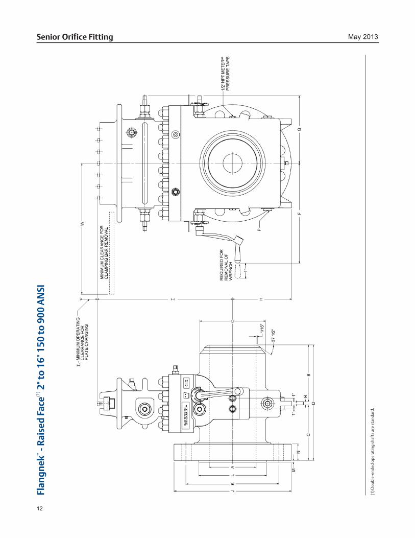
Flan
gn
ek™
- R
aise
d F
ace(1
) 2" t
o 1
6" 1
50 to
900
AN
SI
(1) D
oub
le-e
nded
op
erat
ing
shaf
ts a
re s
tand
ard.

13www.EmersonProcess.com
Technical GuideDifferential Pressure Flow Meters
Standard Trim(2)
Diameter Internal Line Bore
Upstream Face of Orifice Plate to Face of End
Downstream Face of Orifice Plate to Face of End
Overall Face to Face
Operating Clearance from Center
Body Clearance from Center
Clearance to Bottom
Centerline to Top
Clearance for Plate Changing
Diameter of Flange
Diameter of Bolt Circle
Diameter of Raised Face +.005 -.005
Height of Raised Face
Flange Thickness
Bolts / Studs per Flange
Flange Bolts / Studs Diameter
Bolt Length of Bolts/Studs with 2 Hex Nuts
Diameter of Hub at Point of Welding
Size of Drain Plugs(1)
Orifice Plate Thickness
Weight (lb)
Minimum Clearance for Clamping Bar Removal
SIZE
AB
CD
FG
HI
I1J
KL
MN
OP
RW
Cat
alo
g N
o. 0
11-D
anie
l 2-1
6" F
lan
gn
ek-R
aise
d F
ace
150
AN
SIN
AC
E2"
*5
5/1
65
5/1
610
5/8
13
7
414
66
4 3
/4
3 5
/8
1/1
6 1
1/16
4 5
/8
3 1
/4
2.37
5 1
/2
1/8
10
09
NA
CE
3"*
6 1
5/16
6 1
5/16
14
14
85
157
7 1
/2
6 5
1/1
6 7
/8
4 5
/8
3 3
/4
3.50
0 1
/2
1/8
14
011
NA
CE
4"*
6 9
/16
6 9
/16
13 1
/4
15
96
168
9 7
1/2
6
3/1
6 1
/16
7/8
8
5/8
3
3/4
4.
500
3/4
1
/8
185
13N
AC
E6"
*7
15/
167
15/
1616
16
10
719
1011
9
1/2
8
1/2
1
/16
15/
168
3/4
4
6.62
5 3
/4
1/8
26
516
NA
CE
8"*
8 5
/8
8 5
/8
17 1
/2
17
119
2212
13 1
/2
11 3
/4
10 5
/8
1/1
61
1/1
68
3/4
4
1/4
8.
625
3/4
1
/4
345
19A
10"
*6
3/8
6
3/8
13
18
12
825
1416
14
1/4
12
3/4
1
/16
1 1
/8
12 7
/8
4 3
/4
10.7
50 3
/4
1/4
46
522
A12
"*
7 3
/8
6 3
/8
14
19
1310
2816
19
17
15
1/1
61
3/1
612
7/8
4
3/4
12
.750
3/4
1
/4
655
25A
14"
*7
3/8
7
3/8
15
21
15
1132
1821
18
3/4
16
1/4
1
/16
1 5
/16
121
1/8
5
1/2
14
.00
0 3
/4
1/4
94
529
A16
"*
7 7
/16
7 7
/16
15 1
/4
24
1812
3620
23 1
/2
24 1
/4
18 1
/2
1/1
61
7/1
616
1 5
1/2
16
.00
0 3
/4
3/8
1,25
534
Cat
alo
g N
o. 0
13-D
anie
l 2-1
6" F
lan
gn
ek-R
aise
d F
ace
300
AN
SIN
AC
E2"
*5
5/1
65
5/1
610
5/8
13
7
414
66
1/2
5
3 5
/8
1/1
6 1
3/16
8 5
/8
3 1
/2
2.37
5 1
/2
1/8
10
09
NA
CE
3"*
6 1
5/16
6 1
5/16
14
14
85
157
8 1
/4
6 5
/8
5 1
/16
1 1
/16
8 3
/4
4 1
/4
3.50
0 1
/2
1/8
15
011
NA
CE
4"*
6 9/
166
9/1
613
1/4
15
9
616
810
7
1/8
6
3/8
1
/16
1 3
/16
8 3
/4
4 1
/2
4.50
0 3
/4
1/8
20
013
NA
CE
6"*
7 1
5/16
7 1
5/16
16
16
107
1910
12 1
/2 1
0 5
/8
8 1
/2
1/1
61
3/8
12
3/4
4
3/4
6.
625
3/4
1
/8
330
16N
AC
E8"
*8
5/8
8 5
/8
17 1
/2
17
119
2212
15
13
10 5
/8
1/1
61
9/1
612
7/8
5
1/2
8.
625
3/4
1
/4
480
19A
10"
*8
1/8
7 1
/8
15 1
/2
18
129
2514
17 1
/2
15 1
/4
12 3
/4
1/1
61
13/
1616
1 6
1/4
10
.750
3/4
1
/4
615
22A
12"
*8
7/8
7 7
/8
17
19
1311
2816
20 1
/2
17 3
/4
15
1/1
61
15/
1616
1 1
/8
6 3
/4
12.7
50 3
/4
1/4
1,
110
26A
14"
*9
3/8
9 3
/8
19
21
1512
3218
23 2
0 1
/4
16 1
/4
1/1
62
1/1
620
1 1
/8
7 14
.00
0 3
/4
1/4
1,1
0529
A16
"*
8 5
/16
7 7
/16
16
24
1813
3620
25 1
/2 2
2 1
/2
18 1
/2
1/1
62
3/1
620
1 1
/4
7 3
/4
16.0
00
3/4
3/
8 1,
590
34
Cat
alo
g N
o. 0
15-D
anie
l 2-1
6" F
lan
gn
ek-R
aise
d F
ace
600
AN
SIN
AC
E2"
*5
5/1
65
5/1
610
5/8
13
7
414
66
5 3
5/8
1
/4
1 8
5/8
4
1/4
2.
375
1/2
1
/8
105
9N
AC
E3"
*6
15/
166
15/
1614
14
8
515
78
1/4
6
5/8
5
1/4
1
1/4
8
3/4
5
3.50
0 1
/2
1/8
16
011
NA
CE
4"*
6 9
/16
6 9
/16
13 1
/4
15
96
168
10 3
/4
8 1
/2
6 1
6/85
1/4
1
1/2
8
7/8
5
3/4
4.
500
3/4
1
/8
265
13N
AC
E6"
*7
15/
167
15/
1616
16
10
719
1014
11
1/2
8
1/2
1
/4
1 7
/8
121
6 3
/4
6.62
5 3
/4
1/8
40
016
NA
CE
8"*
8 5
/8
8 5
/8
17 1
/2
17
119
2212
16 1
/2
13 3
/4
10 5
/8
1/4
2
3/1
612
1 1
/8
7 3
/4
8.62
5 3
/4
1/4
59
519
A10
"*
9 8
17 1
/4
18
1210
2514
20
17
12 3
/4
1/4
2
1/2
16
1 1
/4
8 1
/2
10.7
50 3
/4
1/4
74
522
A12
"*
9 1
3/16
8 1
3/16
18 7
/8
20
1411
2816
22
19 1
/4
15
1/4
2
5/8
20
1 1
/4
8 3
/4
12.7
50 3
/4
1/4
1,2
1526
A14
"*
10 1
/4
10 1
/4
20 1
/8
21
1512
3218
23 3
/4 2
0 3
/4
16 1
/4
1/4
2
3/4
20
1 3
/8
9 1
/2
14.0
00
3/4
1
/4 1
,475
29A
16"
*10
5/8
10
5/8
21
5/8
24
18
1436
2027
23
3/4
18
1/2
1
/4
3 20
1 1
/2 1
0 1
/4
16.0
00
3/4
3/
8 2,
315
36
Cat
alo
g N
o. 0
16-D
anie
l 2-1
6" F
lan
gn
ek-R
aise
d F
ace
900
AN
SI (u
se P
TFE
Seal
Rin
g o
r SS
R o
nly
)A
2"*
6 1
5/16
6 1
5/16
14
13
75
146
8 1
/2
6 1
/2
3 5
/8
1/4
1
1/2
8
7/8
5
3/4
2.
375
1/2
1
/8
205
11A
3"*
6 1
5/16
6 1
5/16
14
14
85
157
9 1
/2
7 1
/2
5 1
/4
1 1
/2
8 7
/8
5 3
/4
3.50
0 1
/2
1/8
21
511
A4"
*7
13/
167
1/1
615
15
9
616
811
1/2
9
1/4
6
16/
85 1
/4
1 3
/4
81
1/8
6
3/4
4.
500
3/4
1
/8
300
13A
6"*
8 9
/16
7 1
5/16
16 5
/8
16
108
1910
15
12 1
/2
8 1
/2
1/4
2
3/1
612
1 1
/8
7 3
/4
6.62
5 3
/4
1/8
49
016
A8"
*9
1/1
69
1/1
618
5/8
17
11
1022
1218
1/2
15
1/2
10
5/8
1
/4
2 1
/2
121
3/8
8
3/4
8.
625
3/4
1
/4 1
,095
20A
10"
*10
13/
1610
13/
1621
7/8
19
13
1125
1421
1/2
18
1/2
12
3/4
1
/4
2 3
/4
161
3/8
9
1/4
10
.750
3/4
1
/4 1
,555
26A
12"
*11
9/1
611
9/1
623
3/8
21
15
1228
1624
21
15
1
/4
3 1
/8
201
3/8
10
12
.750
3/4
1
/4 1
,935
28A
14"
*11
1/1
611
1/1
622
3/8
22
16
1332
1825
1/4
22
16
1/4
1
/4
3 3
/8
201
1/2
10
1/2
14
.00
0 3
/4
1/4
2,1
1529
A16
"*
9 1
3/16
12 1
/2 2
2 1
1/16
26
2014
3620
27 3
/4
24 1
/4
18 1
/2
1/4
3
1/2
20
1 3
/4
11
16.3
15 3
/4
3/8
CF
36
(1) F
lang
ed p
roce
ss c
onne
ctio
ns a
vaila
ble.
(2) P
leas
e co
nsul
t Dan
iel f
acto
ry o
r rep
rese
ntat
ive
for o
ther
trim
s av
aila
ble
for s
ever
e se
rvic
e an
d ot
her c
ode
requ
irem
ents
, inc
ludi
ng lo
w-t
empe
ratu
re, h
igh
H2S,
Hig
h C
O2, N
OR
SOK
, ISO
516
7, P
ED, D
anie
l “A
ASG
”, a
nd s
peci
al a
pplic
atio
ns.
14 www.EmersonProcess.com
May 2013Senior Orifice Fitting
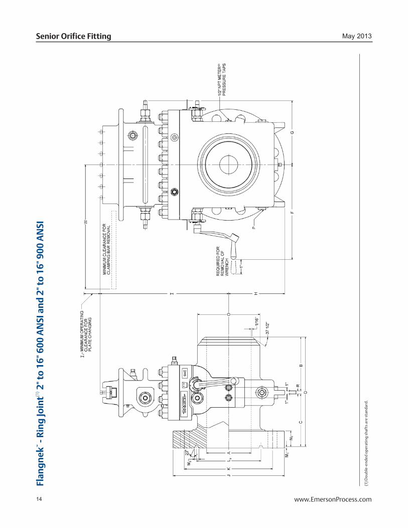
Flan
gn
ek™
- R
ing
Join
t(1) 2
" to
16"
600
AN
SI a
nd
2" t
o 1
6" 9
00 A
NSI
(1) D
oub
le-e
nded
op
erat
ing
shaf
ts a
re s
tand
ard.
15www.EmersonProcess.com
Technical GuideDifferential Pressure Flow Meters
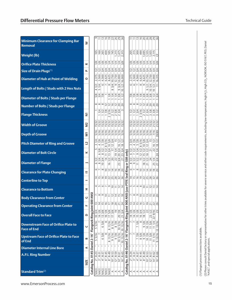
Standard Trim(2)
A.P.I. Ring Number
Diameter Internal Line Bore
Upstream Face of Orifice Plate to Face of End
Downstream Face of Orifice Plate to Face of End
Overall Face to Face
Operating Clearance from Center
Body Clearance from Center
Clearance to Bottom
Centerline to Top
Clearance for Plate Changing
Diameter of Flange
Diameter of Bolt Circle
Pitch Diameter of Ring and Groove
Depth of Groove
Width of Groove
Flange Thickness
Number of Bolts / Studs per Flange
Diameter of Bolts / Studs per Flange
Length of Bolts / Studs with 2 Hex Nuts
Diameter of Hub at Point of Welding
Size of Drain Plugs(1)
Orifice Plate Thickness
Weight (lb)
Minimum Clearance for Clamping Bar Removal
SIZE
AB
CD
FG
HI
I1J
KL2
M1
M2
N1
OP
RW
Cat
alo
g N
o. 0
145-
Dan
iel 2
-16"
Fla
ng
nek
-Rin
g Jo
int
600
AN
SIN
AC
E2"
R-23
*5
5/1
65
5/1
610
3/4
13
74
146
6 1
/2
5 3
1/4
5
/16
15/
321
8 5
/8
4 1
/2
2.37
5 1
/2
1/8
10
59
NA
CE
3"R-
31*
7 7
14 1
/8
148
515
78
1/4
6
5/8
4
7/8
5
/16
15/
321
1/4
8
3/4
5
1/4
3.
500
1/2
1
/8
160
11N
AC
E4"
R-37
*6
5/8
6
5/8
13
3/8
15
96
168
10 3
/4
8 1
/2
5 7
/8
5/1
6 1
5/32
1 1
/2
8 7
/8
6 4.
500
3/4
1
/8
265
13N
AC
E6"
R-45
*8
8 16
1/8
16
107
1910
14
11 1
/2
8 5
/16
5/1
6 1
5/32
1 7
/8
121
7 6.
625
3/4
1
/8
400
16N
AC
E8"
R-49
*8
11/
168
11/
1617
5/8
17
119
2212
16 1
/2
13 3
/4 1
0 5
/8
5/1
6 1
5/32
2 3
/16
121
1/8
8
8.62
5 3
/4
1/4
59
519
A10
"R-
53*
9 1
/16
8 1
/16
17 3
/8
1812
1025
1420
17
12
3/4
5
/16
15/
322
1/2
16
1 1
/4
8 3
/4
10.7
50 3
/4
1/4
74
522
A12
"R-
59*
9 7
/8
8 7
/8
19
2014
1128
1622
19
1/4
15
5
/16
15/
322
5/8
12
1 1
/4
9 12
.750
3/4
1
/4
1,21
526
A14
"R-
61*
10 5
/16
10 5
/16
20 7
/8
2115
1232
1823
3/4
20
3/4
16
1/2
5
/16
15/
322
3/4
20
1 3
/8
9 3
/4 1
4.0
00
3/4
1
/4
1,47
529
A16
"R-
65*
10 1
1/16
10 1
1/16
21 3
/4
2418
1436
2027
23
3/4
18
1/2
5
/16
15/
323
201
1/2
10
1/2
16.
00
0 3
/4
3/8
2,
315
36
Cat
alo
g N
o. 0
146-
Dan
iel 2
-16"
Fla
ng
nek
-Rin
g Jo
int
900
AN
SI (u
se P
TFE
Seal
Rin
g o
r SS
R o
nly
)A
2"R-
24*
7 7
14 1
/8
137
514
68
1/2
6
1/2
3
3/4
5
/16
15/
321
1/2
8
7/8
6
2.37
5 1
/2
1/8
20
511
A3"
R-31
*7
7 14
1/8
14
85
157
9 1
/2
7 1
/2
4 7
/8
5/1
6 1
5/32
1 1
/2
8 7
/8
6 3.
500
1/2
1
/8
215
11A
4"R-
37*
7 7
/8
7 1
/8
15 1
/8
159
616
811
1/2
9
1/4
5
7/8
5
/16
15/
321
3/4
8
1 1
/8
7 4.
500
3/4
1
/8
300
13A
6"R-
45*
8 5
/8
8 16
3/4
16
108
1910
15
12 1
/2
8 5
/16
5/1
6 1
5/32
2 3
/16
121
1/8
8
6.62
5 3
/4
1/8
49
016
A8"
R-49
*9
1/8
9
1/8
18
1/2
17
1110
2212
18 1
/2
15 1
/2 1
0 5
/8
5/1
6 1
5/32
2 1
/2
121
3/8
9
8.62
5 3
/4
1/4
1,
095
20A
10"
R-53
*10
7/8
10
7/8
22
19
1311
2514
21 1
/2
18 1
/2
12 3
/4
5/1
6 1
5/32
2 3
/4
161
3/8
9
1/2
10
.750
3/4
1
/4
1,55
526
A12
"R-
57*
11 5
/8
11 5
/8
23 1
/2
2115
1228
1624
21
15
5
/16
15/
323
1/8
20
1 3
/8
10 1
/4
12.7
50 3
/4
1/4
1,
935
28A
14"
R-62
*11
1/1
611
1/4
22
9/1
622
1613
3218
25 1
/4
22
16 1
/2
7/1
6 2
1/32
3 3
/8
201
1/2
10
1/2
14.
00
0 3
/4
1/4
2,
115
29A
16"
R-66
*9
13/
1612
13/
1623
26
2014
3620
27 3
/4
24 1
/4
18 1
/2
39/
89 2
1/32
3 1
/2
201
3/4
11
16
.315
3/4
3
/8
CF
36
(1
) Fla
nged
pro
cess
con
nect
ions
ava
ilabl
e.
(2) P
leas
e co
nsul
t Dan
iel f
acto
ry o
r rep
rese
ntat
ive
for o
ther
trim
s av
aila
ble
for s
ever
e se
rvic
e an
d ot
her c
ode
requ
irem
ents
, inc
ludi
ng lo
w-t
empe
ratu
re, h
igh
H2S,
Hig
h C
O2, N
OR
SOK
, ISO
516
7, P
ED, D
anie
l “A
ASG
”, a
nd s
peci
al a
pplic
atio
ns.

16 www.EmersonProcess.com
May 2013Senior Orifice Fitting
Flan
gn
ek™
- R
aise
d F
ace(1
) 2" t
o 1
6" 1
500
AN
SI a
nd
2" t
o 1
2" 2
500
AN
SI
(1) D
oub
le-e
nded
op
erat
ing
shaf
ts a
re s
tand
ard.
17www.EmersonProcess.com
Technical GuideDifferential Pressure Flow Meters
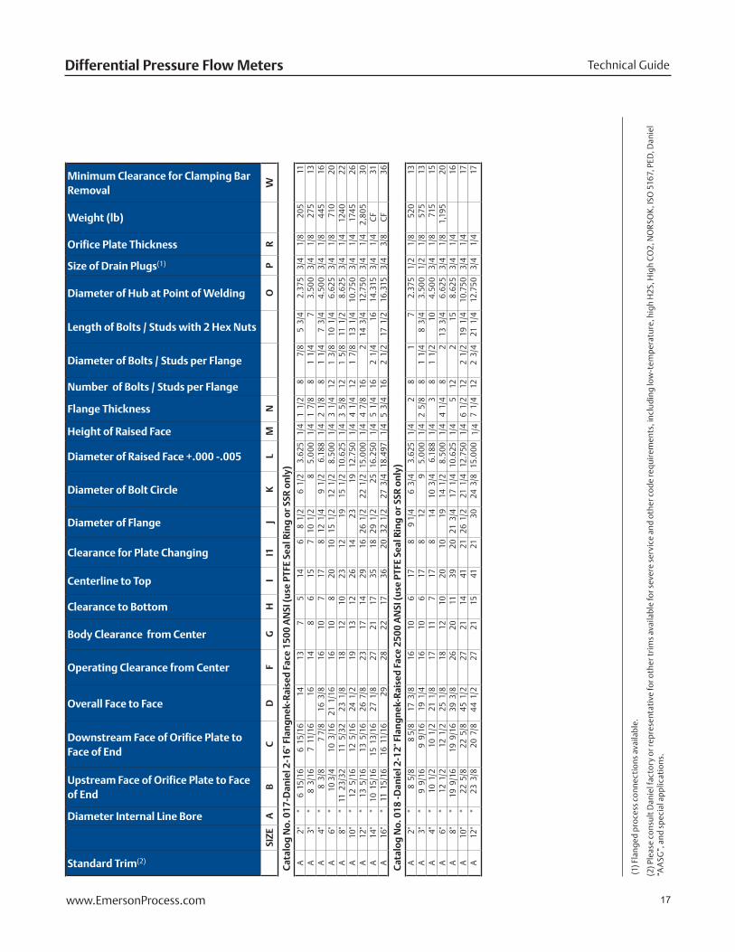
Standard Trim(2)
Diameter Internal Line Bore
Upstream Face of Orifice Plate to Face of End
Downstream Face of Orifice Plate to Face of End
Overall Face to Face
Operating Clearance from Center
Body Clearance from Center
Clearance to Bottom
Centerline to Top
Clearance for Plate Changing
Diameter of Flange
Diameter of Bolt Circle
Diameter of Raised Face +.000 -.005
Height of Raised Face
Flange Thickness
Number of Bolts / Studs per Flange
Diameter of Bolts / Studs per Flange
Length of Bolts / Studs with 2 Hex Nuts
Diameter of Hub at Point of Welding
Size of Drain Plugs(1)
Orifice Plate Thickness
Weight (lb)
Minimum Clearance for Clamping Bar Removal
SIZE
AB
CD
FG
HI
I1J
KL
MN
OP
RW
Cat
alo
g N
o. 0
17-D
anie
l 2-1
6" F
lan
gn
ek-R
aise
d F
ace
1500
AN
SI (u
se P
TFE
Seal
Rin
g o
r SS
R o
nly
)A
2"*
6 1
5/16
6 1
5/16
14
137
514
68
1/2
6
1/2
3.
625
1/4
1
1/2
8
7/8
5
3/4
2.
375
3/4
1
/8
205
11A
3"*
8 3
/16
7 1
1/16
16
148
615
710
1/2
8
5.0
00
1/4
1
7/8
8
1 1
/4
7 3.
500
3/4
1
/8
275
13A
4"*
8 3
/8
7 7/
8 16
3/8
16
107
178
12 1
/4
9 1
/2
6.18
8 1
/4
2 1
/8
81
1/4
7
3/4
4.
500
3/4
1
/8
445
16A
6"*
10 3
/4
10 3
/16
21 1
/16
1610
820
1015
1/2
12
1/2
8.
500
1/4
3
1/4
12
1 3
/8
10 1
/4
6.62
5 3
/4
1/8
71
020
A8"
*11
23/
3211
5/3
223
1/8
18
1210
2312
19
15 1
/2
10.6
25 1
/4
3 5
/8
121
5/8
11
1/2
8.
625
3/4
1
/4
1240
22A
10"
*12
5/1
612
5/1
624
1/2
19
1312
2614
23
19
12.7
50 1
/4
4 1
/4
121
7/8
13
1/4
10
.750
3/4
1
/4
1745
26A
12"
*13
5/1
613
5/1
626
7/8
23
1714
2916
26 1
/2
22 1
/2
15.0
00
1/4
4
7/8
16
2 14
3/4
12
.750
3/4
1
/4
2,80
530
A14
"*
10 1
5/16
15 1
3/16
27 1
/8
2721
1735
1829
1/2
25
16
.250
1/4
5
1/4
16
2 1
/4
16
14.3
15 3
/4
1/4
C
F31
A16
"*
11 1
5/16
16 1
1/16
29
2822
1736
2032
1/2
27
3/4
18
.497
1/4
5
3/4
16
2 1
/2
17 1
/2
16.3
15 3
/4
3/8
C
F36
Cat
alo
g N
o. 0
18 -D
anie
l 2-1
2" F
lan
gn
ek-R
aise
d F
ace
2500
AN
SI (u
se P
TFE
Seal
Rin
g o
r SS
R o
nly
)A
2"*
8 5
/8
8 5/
8 17
3/8
16
106
178
9 1/
4 6
3/4
3.
625
1/4
2
81
7 2.
375
1/2
1
/8
520
13A
3"*
9 9
/16
9 9
/16
19 1
/4
1610
617
812
9
5.0
00
1/4
2
5/8
8
1 1
/4
8 3
/4
3.50
0 1
/2
1/8
57
513
A4"
*10
1/2
10
1/2
21
1/8
17
117
178
14
10 3
/4
6.18
8 1
/4
3 8
1 1
/2
10
4.50
0 3
/4
1/8
71
515
A6"
*12
1/2
12
1/2
25
1/8
18
1210
2010
19
14 1
/2
8.50
0 1
/4
4 1
/4
82
13 3
/4
6.62
5 3
/4
1/8
1,
195
20A
8"*
19 9
/16
19 9
/16
39 3
/8
2620
1139
2021
3/4
17
1/4
10
.625
1/4
5
122
15
8.62
5 3
/4
1/4
16
A10
"*
22 5
/8
22 5
/8
45 1
/2
2721
1441
2126
1/2
21
1/4
12
.750
1/4
6
1/2
12
2 1
/2
19 1
/4
10.7
50 3
/4
1/4
17
A12
"*
23 3
/8
20 7
/8
44
1/2
27
2115
4121
30
24 3
/8
15.0
00
1/4
7
1/4
12
2 3
/4
21 1
/4
12.7
50 3
/4
1/4
17
(1) F
lang
ed p
roce
ss c
onne
ctio
ns a
vaila
ble.
(2) P
leas
e co
nsul
t Dan
iel f
acto
ry o
r rep
rese
ntat
ive
for o
ther
trim
s av
aila
ble
for s
ever
e se
rvic
e an
d ot
her c
ode
requ
irem
ents
, inc
ludi
ng lo
w-t
empe
ratu
re, h
igh
H2S
, Hig
h C
O2,
NO
RSO
K, I
SO 5
167,
PED
, Dan
iel
“AA
SG”,
and
spe
cial
app
licat
ions
.
18 www.EmersonProcess.com
May 2013Senior Orifice Fitting
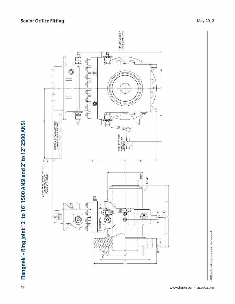
Flan
gn
ek™
- R
ing
Join
t(1) 2
" to
16"
150
0 A
NSI
an
d 2
" to
12"
250
0 A
NSI
(1) D
oub
le-e
nded
op
erat
ing
shaf
ts a
re s
tand
ard.
19www.EmersonProcess.com
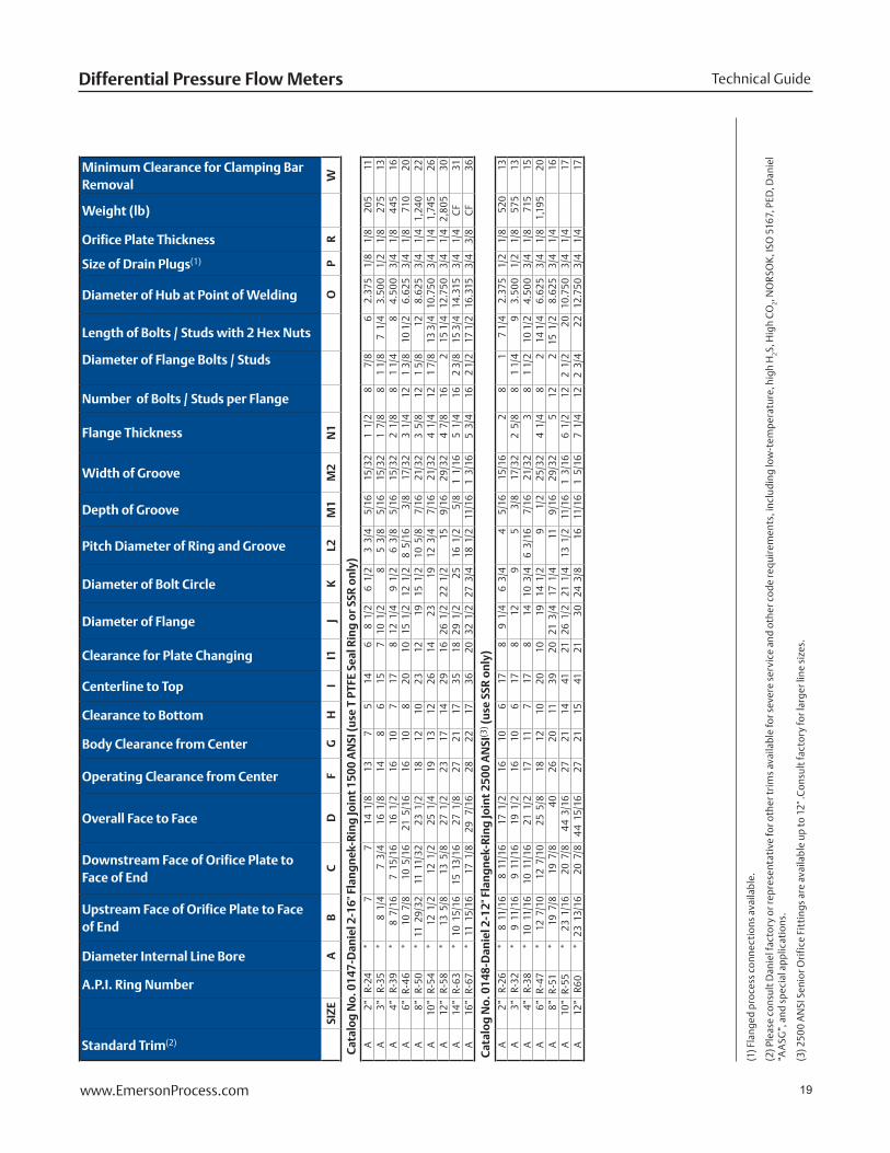
Technical GuideDifferential Pressure Flow Meters
Standard Trim(2)
A.P.I. Ring Number
Diameter Internal Line Bore
Upstream Face of Orifice Plate to Face of End
Downstream Face of Orifice Plate to Face of End
Overall Face to Face
Operating Clearance from Center
Body Clearance from Center
Clearance to Bottom
Centerline to Top
Clearance for Plate Changing
Diameter of Flange
Diameter of Bolt Circle
Pitch Diameter of Ring and Groove
Depth of Groove
Width of Groove
Flange Thickness
Number of Bolts / Studs per Flange
Diameter of Flange Bolts / Studs
Length of Bolts / Studs with 2 Hex Nuts
Diameter of Hub at Point of Welding
Size of Drain Plugs(1)
Orifice Plate Thickness
Weight (lb)
Minimum Clearance for Clamping Bar Removal
SIZE
AB
CD
FG
HI
I1J
KL2
M1
M2
N1
OP
RW
Cat
alo
g N
o. 0
147-
Dan
iel 2
-16"
Fla
ng
nek
-Rin
g Jo
int
1500
AN
SI (u
se T
PTF
E Se
al R
ing
or
SSR
on
ly)
A2”
R-24
*7
7 14
1/8
13
75
146
8 1
/2
6 1
/2
3 3
/4
5/1
6 1
5/32
1 1
/2
8 7
/8
6 2.
375
1/8
1
/8
205
11A
3”R-
35*
8 1
/4
7 3
/4
16 1
/8
148
615
710
1/2
8
5 3
/8
5/1
6 1
5/32
1 7
/8
81
1/8
7 1
/4
3.50
0 1
/2
1/8
27
513
A4”
R-39
*8
7/1
67
15/
1616
1/2
16
107
178
12 1
/4
9 1
/2
6 3
/8
5/1
6 1
5/32
2 1
/8
81
1/4
8 4.
500
3/4
1
/8
445
16A
6”R-
46*
10 7
/8
10 5
/16
21 5
/16
1610
820
1015
1/2
12
1/2
8
5/1
6 3
/8
17/
323
1/4
12
1 3/
8 10
1/2
6.
625
3/4
1
/8
710
20A
8”R-
50*
11 2
9/32
11 1
1/32
23 1
/2
1812
1023
1219
15
1/2
10
5/8
7
/16
21/
323
5/8
12
1 5/
8 12
8.
625
3/4
1
/4
1,24
022
A10
”R-
54*
12 1
/2
12 1
/2
25 1
/4
1913
1226
1423
19
12
3/4
7
/16
21/
324
1/4
12
1 7/
8 13
3/4
10
.750
3/4
1
/4
1,74
526
A12
”R-
58*
13 5
/8
13 5
/8
27 1
/2
2317
1429
1626
1/2
22
1/2
15
9
/16
29/
324
7/8
16
2 15
1/4
12
.750
3/4
1
/4
2,80
530
A14
”R-
63*
10 1
5/16
15 1
3/16
27 1
/8
2721
1735
1829
1/2
25
16
1/2
5
/8
1 1
/16
5 1
/4
162
3/8
15 3
/4
14.3
15 3
/4
1/4
C
F31
A16
”R-
67*
11 1
5/16
17 1
/8
29
7/16
2822
1736
2032
1/2
27
3/4
18
1/2
1
1/16
1 3
/16
5 3
/4
162
1/2
17 1
/2
16.3
15 3
/4
3/8
C
F36
Cat
alo
g N
o. 0
148-
Dan
iel 2
-12"
Fla
ng
nek
-Rin
g Jo
int
2500
AN
SI(3
) (u
se S
SR o
nly
)A
2”R-
26*
8 1
1/16
8 1
1/16
17 1
/2
1610
617
89
1/4
6
3/4
4
5/1
6 1
5/16
2 8
1 7
1/4
2.37
5 1
/2
1/8
52
013
A3”
R-32
*9
11/
169
11/
1619
1/2
16
106
178
12
9 5
3/8
1
7/32
2 5
/8
81
1/4
9 3.
500
1/2
1
/8
575
13A
4”R-
38*
10 1
1/16
10 1
1/16
21 1
/2
1711
717
814
10
3/4
6
3/1
6 7
/16
21/
323
81
1/2
10 1
/2
4.50
0 3
/4
1/8
71
515
A6”
R-47
*12
7/1
012
7/1
025
5/8
18
1210
2010
19
14 1
/2
9 1
/2
25/
324
1/4
8
2 14
1/4
6.
625
3/4
1
/8
1,19
520
A8”
R-51
*19
7/8
19
7/8
40
26
2011
3920
21 3
/4
17 1
/4
11
9/1
6 2
9/32
5 12
2 15
1/2
8.
625
3/4
1
/4
16A
10”
R-55
*23
1/1
620
7/8
4
4 3
/16
2721
1441
2126
1/2
21
1/4
13
1/2
1
1/16
1 3
/16
6 1
/2
122
1/2
20
10
.750
3/4
1
/4
17A
12”
R60
*23
13/
1620
7/8
4
4 1
5/16
2721
1541
2130
24
3/8
16
1
1/16
1 5
/16
7 1
/4
122
3/4
22
12
.750
3/4
1
/4
17
(1
) Fla
nged
pro
cess
con
nect
ions
ava
ilabl
e.
(2) P
leas
e co
nsul
t Dan
iel f
acto
ry o
r rep
rese
ntat
ive
for o
ther
trim
s av
aila
ble
for s
ever
e se
rvic
e an
d ot
her c
ode
requ
irem
ents
, inc
ludi
ng lo
w-t
empe
ratu
re, h
igh
H2S,
Hig
h C
O2, N
OR
SOK
, ISO
516
7, P
ED, D
anie
l “A
ASG
”, a
nd s
peci
al a
pplic
atio
ns.
(3) 2
500
AN
SI S
enio
r Ori
fice
Fit
ting
s ar
e av
aila
ble
up to
12"
.Con
sult
fact
ory
for l
arge
r lin
e si
zes.

20 www.EmersonProcess.com
May 2013Senior Orifice Fitting
Flan
ged
- R
aise
d F
ace(1
) 10"
to 1
6" 1
50 to
600
AN
SI 2
" to
16"
900
AN
SI
(1) D
oubl
e-en
ded
oper
atin
g sh
afts
are
sta
ndar
d.

21www.EmersonProcess.com
Technical GuideDifferential Pressure Flow Meters
Standard Trim(2)
Diameter Internal Line Bore
Upstream Face of Orifice Plate to Face of End
Downstream Face of Orifice Plate to Face of End
Overall Face to Face
Operating Clearance from Center
Body Clearance from Center
Clearance to Bottom
Centerline to Top
Clearance for Plate Changing
Diameter of Flange
Diameter of Bolt Circle
Diameter of Raised Face +.005 -.005
Height of Raised Face
Flange Thickness
Number of Bolts / Studs per Flange
Diameter of Flange Bolts/Studs
Length of Bolts / Studs with 2 Hex Nuts
Size of Drain Plugs(1)
Orifice Plate Thickness
Weight (lb)
Minimum Clearance for Clamping Bar Removal
SIZE
AB
CD
FG
HI
I1J
KL
MN
PR
W
Cat
alo
g N
o. 1
01-D
anie
l 10-
16" F
lan
ged
-Rai
sed
Fac
e 15
0 A
NSI
A10
"*
6 3
/8
6 3
/8
13
1812
825
13 1
/8
16
14 1
/4
12 3
/4
1/1
61
1/8
12
7/8
4
3/4
3
/4
1/4
51
022
A12
"*
7 3
/8
6 3
/8
14
1913
1029
15
19
17
15
1/1
61
3/1
612
7/8
4
3/4
3
/4
1/4
72
026
A14
"*
7 3
/8
7 3
/8
15
2115
1132
17 9
/16
21
18 3
/4
16 1
/4
1/1
61
5/1
612
1 5
1/2
3
/4
1/4
1,
030
29A
16"
*8
3/1
67
7/1
616
24
1812
3619
1/2
23
1/2
21
1/4
18
1/2
1
/16
1 7
/16
161
5 1
/2
3/4
3
/8
1,35
034
Cat
alo
g N
o. 1
03-D
anie
l 10-
16" F
lan
ged
-Rai
sed
Fac
e 30
0 A
NSI
A10
"*
8 1
/8
7 1
/8
15 1
/2
1812
925
13 1
/8
17 1
/2
15 1
/4
12 3
/4
1/1
61
13/
1616
1 6
1/4
3
/4
1/4
69
522
A12
"*
8 7
/8
7 7
/8
17
1913
1129
15 2
0 1
/2
17 3
/4
15
1/1
61
15/
1616
1 1
/8
6 3
/4
3/4
1
/4
1,22
526
A14
"*
9 3
/8
9 3
/8
19
2115
1232
17 9
/16
23
20 1
/4
16 1
/4
1/1
62
1/1
620
1 1
/8
7 3
/4
1/4
1,
270
29A
16"
*9
1/1
68
5/1
617
3/4
24
1813
3619
1/2
25
1/2
22
1/2
18
1/2
1
/16
2 3
/16
201
1/4
7
3/4
3
/4
3/8
1,
810
34
Cat
alo
g N
o. 1
05-D
anie
l 10-
16" F
lan
ged
-Rai
sed
Fac
e 60
0 A
NSI
A10
"*
9 8
17 1
/4
1812
1025
13 1
/8
20
17
12 3
/4
1/4
2
1/2
16
1 1
/4
8 1
/2
3/4
1
/4
920
22A
12"
*9
13/
168
1/1
618
7/8
20
1411
2915
22
19
1/4
15
1
/4
2 5
/8
201
1/4
8
3/4
3
/4
1/4
1,
430
26A
14"
*10
1/4
10
1/2
20
3/4
21
1512
3217
9/1
623
3/4
20
3/4
16
1/4
1
/4
2 3
/4
201
3/8
9
1/2
3
/4
1/4
1,
735
29A
16"
*10
5/8
10
5/8
21
5/8
24
1814
3619
1/2
27
23
3/4
18
1/2
1
/4
3 20
1 1
/2
10 1
/4
3/4
3
/8
2,68
036
Cat
alo
g N
o. 1
06-D
anie
l 2-1
6" F
lan
ged
-Rai
sed
Fac
e 90
0 A
NSI
(use
PTF
E Se
al R
ing
or
SSR
on
ly)
A2"
*6
15/
166
15/
1614
13
75
145
9/1
68
1/2
6
1/2
3
5/8
1
/4
1 1
/2
8 7
/8
5 3
/4
1/2
1
/8
230
11A
3"*
6 1
5/16
6 1
5/16
14
148
515
6 1
/16
9 1
/2
7 1
/2
5 1
/4
1 1
/2
8 7
/8
5 3
/4
1/2
1
/8
245
11A
4"*
7 1
3/16
7 1
/16
15
159
616
7 11
1/2
9
1/4
6
3/1
6 1
/4
1 3
/4
81
1/8
6
3/4
3
/4
1/8
35
513
A6"
*8
9/1
67
15/
1616
5/8
16
108
198
15
12 1
/2
8 1
/2
1/4
2
3/1
612
1 1
/8
7 3
/4
3/4
1
/8
600
16A
8"*
9 1
/16
9 1
/16
18 3
/8
1711
1022
11
18 1
/2
15 1
/2
10 5
/8
1/4
2
1/2
12
1 3
/8
8 3
/4
3/4
1
/4
1,26
520
A10
"*
10 1
3/16
10 1
3/16
21 7
/8
1913
1125
13 1
/8
21 1
/2
18 1
/2
12 3
/4
1/4
2
3/4
16
1 3
/8
9 1
/4
3/4
1
/4
1,80
026
A12
"*
11 9
/16
11 9
/16
23 3
/8
2115
1229
15
24
21
15
1/4
3
1/8
20
1 3
/8
10
3/4
1
/4
2,26
028
A14
"*
11 1
/16
11 1
/16
22 3
/8
2317
1332
17 9
/16
25 1
/4
22
16 3
/4
1/4
3
3/8
20
1 1
/2
10 1
/2
3/4
1
/4
2,49
529
A16
"*
12 1
1/16
12 1
1/16
25 3
/8
2418
1437
19 1
/2 2
7 3
/4
24 1
/4
18 1
/2
1/4
3
1/2
20
1 3
/4
11
3/4
3
/8
4,69
336
(1
) Fla
nged
pro
cess
con
nect
ions
ava
ilabl
e.
(2) P
leas
e co
nsul
t Dan
iel f
acto
ry o
r rep
rese
ntat
ive
for o
ther
trim
s av
aila
ble
for s
ever
e se
rvic
e an
d ot
her c
ode
requ
irem
ents
, inc
ludi
ng lo
w-t
empe
ratu
re, h
igh
H2S,
Hig
h C
O2, N
OR
SOK
, ISO
516
7, P
ED, D
anie
l “A
ASG
”, a
nd s
peci
al a
pplic
atio
ns.
22 www.EmersonProcess.com
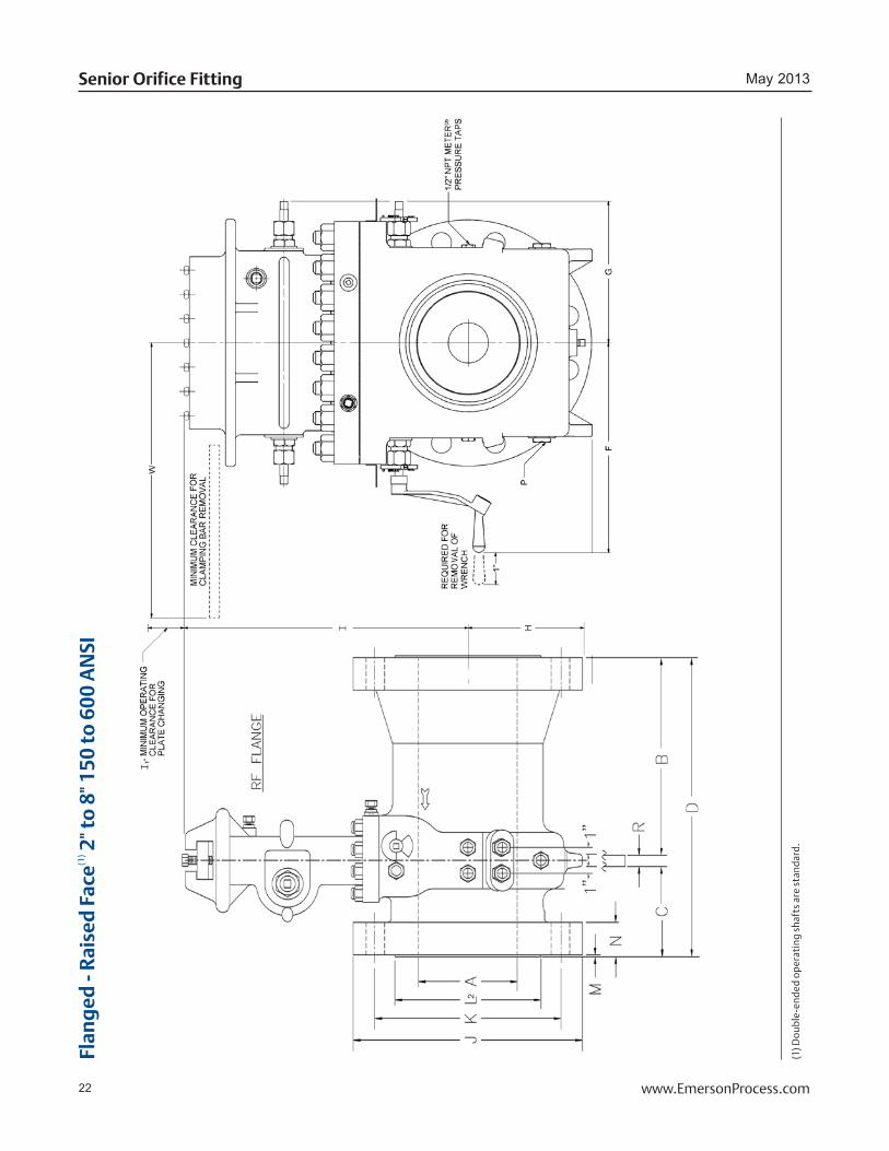
May 2013Senior Orifice Fitting
Flan
ged
- R
aise
d F
ace(1
) 2" t
o 8
" 150
to 6
00 A
NSI
(1) D
oubl
e-en
ded
oper
atin
g sh
afts
are
sta
ndar
d.

23www.EmersonProcess.com
Technical GuideDifferential Pressure Flow Meters
Standard Trim(3)
Diameter Internal Line Bore
Upstream Face of Orifice Plate to Face of End
Downstream Face of Orifice Plate to Face of End(2)
Overall Face to Face(2)
Operating Clearance from Center
Body Clearance from Center
Clearance to Bottom
Centerline to Top
Clearance for Plate Changing
Diameter of Flange
Diameter of Bolt Circle
Diameter of Raised Face +.005 -.005
Height of Raised Face
Flange Thickness
Number of Bolts / Studs per Flange
Diameter of Flange Bolts / Studs
Length of Bolts / Studs with 2 Hex Nuts
Size of Drain Plugs(1)
Orifice Plate Thickness
Weight (lb)
Minimum Clearance for Clamping Bar Removal
SIZE
AB
CD
FG
HI
I1J
KL
MN
PR
W
Cat
alo
g N
o. 1
01-D
anie
l 2-8
" Fla
ng
ed-R
aise
d F
ace
150
AN
SIN
AC
E2"
*7
13/
165
5/1
613
1/8
13
74
145
9/1
66
4 3
/4
3 5
/8
1/1
6 1
1/16
4 5
/8
3 1
/4
1/2
1
/8
105
9N
AC
E3"
*11
3/8
5 3
/816
3/4
148
515
6 1
/16
7 1
/2
6 5
1/1
6 7
/8
4 5
/8
3 3
/4
1/2
1
/8
150
11N
AC
E4"
*10
3/8
5 1
/216
1/4
159
616
7 9
7 1
/2
6 3
/16
1/1
6 7
/8
8 5
/8
3 3
/4
3/4
1
/8
245
13N
AC
E6"
*13
7/8
5 5
/819
1/2
16
107
198
11
9 1
/2
8 1
/2
1/1
6 1
5/16
8 3
/4
4 3
/4
1/8
28
516
NA
CE
8"*
15 1
/46
1/4
21 1
/2
1711
922
11
13 1
/2
11 3
/4
10 5
/8
1/1
61
1/1
68
3/4
4
1/4
3
/4
1/4
37
519
Cat
alo
g N
o. 1
03-D
anie
l 2-8
" Fla
ng
ed-R
aise
d F
ace
300
AN
SIN
AC
E2"
*8
1/1
65
5/1
613
3/8
137
414
5 9
/16
6 1
/2
5 3
5/8
1
/16
13/
168
5/8
3
1/2
1
/2
1/8
11
09
NA
CE
3"*
11 9
/16
5 9
/16
17 1
/814
85
156
1/1
68
1/4
6
5/8
5
1/1
61
1/1
68
3/4
4
1/4
1
/2
1/8
16
511
NA
CE
4"*
10 1
5/16
5 1
1/16
16 5
/815
96
167
10
7 1
/8
6 3
/16
1/1
61
3/1
68
3/4
4
1/2
3
/4
1/8
22
013
NA
CE
6"*
12 7
/87
19 7
/816
107
198
12 1
/2
10 5
/8
8 1
/2
1/1
61
3/8
12
3/4
5
3/4
1
/8
370
16N
AC
E8"
*14
1/2
721
1/2
1711
922
11
15
13
10 5
/8
1/1
61
9/1
612
7/8
5
1/2
3
/4
1/4
54
019
Cat
alo
g N
o. 1
05-D
anie
l 2-8
" Fla
ng
ed-R
aise
d F
ace
600
AN
SIN
AC
E2"
*8
7/1
65
5/1
613
3/4
137
414
5 9
/16
6 5
3 5
/8
1/4
1
8 5
/8
4 1
/4
1/2
1
/8
115
9N
AC
E3"
*10
1/2
717
1/2
14
85
156
1/1
68
1/4
6
5/8
5
1/4
1
1/4
8
3/4
5
1/2
1
/8
175
11N
AC
E4"
*10
7/8
6 5
/817
1/2
159
616
7 10
3/4
8
1/2
6
3/1
6 1
/4
1 1
/2
8 7
/8
5 3
/4
3/4
1
/8
300
13N
AC
E6"
*12
7/8
820
7/8
1610
719
8 14
11
1/2
8
1/2
1
/4
1 7
/8
121
6 3
/4
3/4
1
/8
480
16N
AC
E8"
*14
1/4
8 3
/423
1711
922
11
16 1
/2
13 3
/4
10 5
/8
1/4
2
3/1
612
1 1/
8 7
3/4
3
/4
1/4
71
019
(1
) Fla
nged
pro
cess
con
nect
ions
ava
ilabl
e.
(2) T
he fl
ange
-by-
flan
ge (F
x F
) con
figu
rati
on o
f the
2" t
o 8"
Sen
ior O
rifi
ce F
itti
ngs
has
chan
ged.
Thi
s ch
ange
app
lies
to A
NSI
cla
sses
150
to 6
00
only
. Th
e fl
ange
-by-
flan
ge c
onfi
gura
tion
has
bee
n re
plac
ed
wit
h a
rais
ed-f
ace
or ri
ng-t
ype-
join
t Fla
ngne
k (R
FFN
or R
TJ F
N) c
onfi
gura
tion
feat
urin
g a
flan
ge w
elde
d to
the
upst
ream
sid
e (i
nlet
)of t
he F
lang
nek
fitt
ing.
Thi
s m
eans
the
face
-to
-fac
e di
men
sion
s ar
e lo
nger
th
an p
revi
ous
vers
ions
and
will
not
retr
ofit
into
the
void
of a
ny o
ld s
tyle
F x
F S
enio
r Ori
fice
Fit
ting
pur
chas
ed p
rior
to A
ugus
t 201
2. T
o re
plac
e di
scon
tinu
ed F
x F
mod
els,
exi
stin
g pi
ping
mus
t be
mod
ifie
d to
ac
com
mod
ate
the
adde
d le
ngth
.
(3) P
leas
e co
nsul
t Dan
iel f
acto
ry o
r rep
rese
ntat
ive
for o
ther
trim
s av
aila
ble
for s
ever
e se
rvic
e an
d ot
her c
ode
requ
irem
ents
, inc
ludi
ng lo
w-t
empe
ratu
re, h
igh
H2S,
Hig
h C
O2, N
OR
SOK
, ISO
516
7, P
ED, D
anie
l “A
ASG
”, a
nd s
peci
al a
pplic
atio
ns.
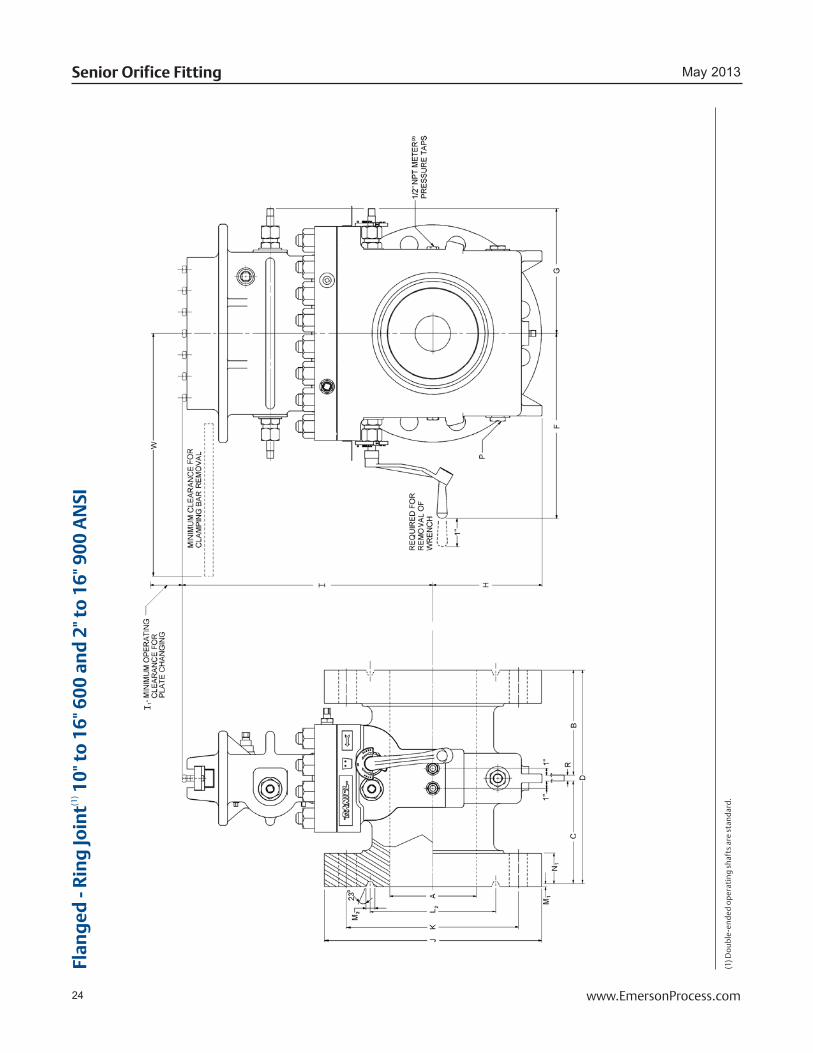
24 www.EmersonProcess.com
May 2013Senior Orifice Fitting
Flan
ged
- R
ing
Join
t(1) 1
0" to
16"
600
an
d 2
" to
16"
900
AN
SI
(1) D
oub
le-e
nded
op
erat
ing
shaf
ts a
re s
tand
ard.
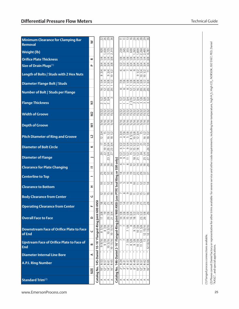
25www.EmersonProcess.com
Technical GuideDifferential Pressure Flow Meters
Standard Trim(2)
A.P.I. Ring Number
Diameter Internal Line Bore
Upstream Face of Orifice Plate to Face of End
Downstream Face of Orifice Plate to Face of End
Overall Face to Face
Operating Clearance from Center
Body Clearance from Center
Clearance to Bottom
Centerline to Top
Clearance for Plate Changing
Diameter of Flange
Diameter of Bolt Circle
Pitch Diameter of Ring and Groove
Depth of Groove
Width of Groove
Flange Thickness
Number of Bolt / Studs per Flange
Diameter Flange Bolt / Studs
Length of Bolts / Studs with 2 Hex Nuts
Size of Drain Plugs(1)
Orifice Plate Thickness
Weight (lb)
Minimum Clearance for Clamping Bar Removal
SIZE
AB
CD
FG
HI
I1J
KL2
M1
M2
N1
PR
W
Cat
alo
g N
o. 1
45-D
anie
l 10-
16" F
lan
ged
-Rin
g Jo
int
600
AN
SIA
10"
R-53
*9
9/1
68
1/1
617
3/8
18
1210
2514
20
17
12 3
/4
5/1
6 1
5/32
2 1
/2
161
1/4
8
3/4
3
/4
1/4
920
22A
12"
R-57
*9
7/8
8
7/8
19
20
1411
2916
22
19 1
/4
15
5/1
6 1
5/32
2 5
/8
121
1/4
9
3/4
1/
4 1,
430
26A
14"
R-61
*10
5/1
610
5/1
620
7/8
21
1512
3218
23 3
/4 2
0 3
/4
16 1
/2
5/1
6 1
5/32
2 3
/4
201
3/8
9
3/4
3
/4
1/4
1,73
529
A16
"R-
65*
10 1
1/16
10 1
1/16
21 3
/4
2418
1436
2027
23
3/4
18
1/2
5
/16
15/
323
201
1/2
10
1/2
3
/8
3/8
2,31
536
Cat
alo
g N
o. 1
46-D
anie
l 2-1
6" F
lan
ged
-Rin
g Jo
int
900
AN
SI (u
se P
TFE
Seal
Rin
g o
r SS
R o
nly
)A
2"R-
24*
7 7
14 1
/8
137
514
68
1/2
6
1/2
3
3/4
5
/16
15/
321
1/2
8
7/8
6
1/2
1/
8 23
011
A3"
R-31
*7
7 14
1/8
14
85
157
9 1
/2
7 1
/2
4 7
/8
5/1
6 1
5/32
1 1
/2
8 7
/8
6 1
/2
1/8
245
11A
4"R-
37*
7 7
/8
7 1
/8
15 1
/8
159
616
811
1/2
9
1/4
5
7/8
5
/16
15/
321
3/4
8
1 1
/8
7 3
/4
1/8
355
13A
6"R-
45*
8 5
/8
8 16
3/4
16
108
1910
15
12 1
/2
8 5
/16
5/1
6 1
5/32
2 3
/16
121
1/8
8
3/4
1/
8 60
016
A8"
R-49
*9
1/8
9
1/8
18
1/2
17
1110
2212
18 1
/2
15 1
/2
10 5
/8
5/1
6 1
5/32
2 1
/2
121
3/8
9
3/4
1/
4 1,
265
20A
10"
R-53
*10
7/8
10
7/8
22
19
1311
2514
21 1
/2
18 1
/2
12 3
/4
5/1
6 1
5/32
2 3
/4
161
3/8
9
1/2
3
/4
1/4
1,80
026
A12
"R-
57*
11 5
/8
11 5
/8
23 1
/2
2115
1229
1624
21
15
5
/16
15/
323
1/8
20
1 3
/8
10 1
/4
3/4
1/
4 2,
260
28A
14"
R-62
*13
12
15/
1626
1/8
23
1713
3218
25 1
/4
22
16 1
/2
7/1
6 1
5/32
3 3
/8
201
1/2
10
1/2
3
/4
1/4
2,49
529
A16
"R-
66*
12 1
3/16
12 1
3/16
26
2418
1437
2027
3/4
24
1/4
18
1/2
7/
16 2
1/32
3 1
/2
201
3/4
11
3
/4
3/8
4,78
136
(1
) Fla
nged
pro
cess
con
nect
ions
ava
ilabl
e.
(2) P
leas
e co
nsul
t Dan
iel f
acto
ry o
r rep
rese
ntat
ive
for o
ther
trim
s av
aila
ble
for s
ever
e se
rvic
e an
d ot
her c
ode
requ
irem
ents
, inc
ludi
ng lo
w-t
empe
ratu
re, h
igh
H2S,
Hig
h C
O2, N
OR
SOK
, ISO
516
7, P
ED, D
anie
l “A
ASG
”, a
nd s
peci
al a
pplic
atio
ns.

26 www.EmersonProcess.com
May 2013Senior Orifice Fitting
Flan
ged
- R
ing
Join
t(1) 2
" to
8" 6
00 A
NSI
(1) D
oub
le-e
nded
op
erat
ing
shaf
ts a
re s
tand
ard.
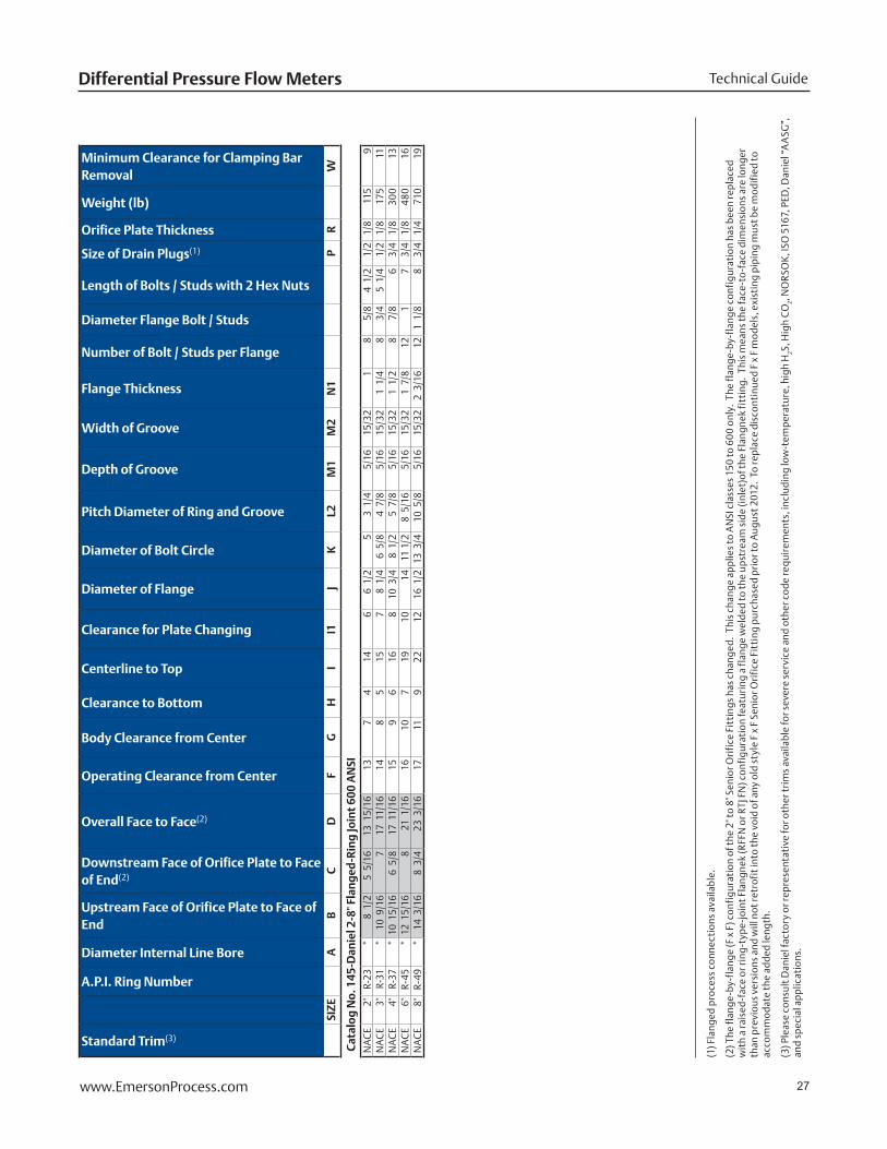
27www.EmersonProcess.com
Technical GuideDifferential Pressure Flow Meters
Standard Trim(3)
A.P.I. Ring Number
Diameter Internal Line Bore
Upstream Face of Orifice Plate to Face of End
Downstream Face of Orifice Plate to Face of End(2)
Overall Face to Face(2)
Operating Clearance from Center
Body Clearance from Center
Clearance to Bottom
Centerline to Top
Clearance for Plate Changing
Diameter of Flange
Diameter of Bolt Circle
Pitch Diameter of Ring and Groove
Depth of Groove
Width of Groove
Flange Thickness
Number of Bolt / Studs per Flange
Diameter Flange Bolt / Studs
Length of Bolts / Studs with 2 Hex Nuts
Size of Drain Plugs(1)
Orifice Plate Thickness
Weight (lb)
Minimum Clearance for Clamping Bar Removal
SIZE
AB
CD
FG
HI
I1J
KL2
M1
M2
N1
PR
W
Cat
alo
g N
o. 1
45-D
anie
l 2-8
" Fla
ng
ed-R
ing
Join
t 60
0 A
NSI
NA
CE
2"R-
23*
8 1
/2
5 5
/16
13 1
5/16
137
414
66
1/2
5
3 1
/4
5/1
6 1
5/32
1 8
5/8
4
1/2
1
/2
1/8
115
9N
AC
E3"
R-31
*10
9/1
67
17 1
1/16
148
515
78
1/4
6
5/8
4
7/8
5
/16
15/
321
1/4
8
3/4
5
1/4
1
/2
1/8
175
11N
AC
E4"
R-37
*10
15/
166
5/8
17
11/
1615
96
168
10 3
/4
8 1
/2
5 7
/8
5/1
6 1
5/32
1 1
/2
8 7
/8
6 3
/4
1/8
300
13N
AC
E6"
R-45
*12
15/
168
21 1
/16
1610
719
1014
11
1/2
8
5/1
6 5
/16
15/
321
7/8
12
1 7
3/4
1/
8 48
016
NA
CE
8"R-
49*
14 3
/16
8 3
/4
23 3
/16
1711
922
1216
1/2
13
3/4
10
5/8
5
/16
15/
322
3/1
612
1 1
/8
8 3
/4
1/4
710
19
(1
) Fla
nged
pro
cess
con
nect
ions
ava
ilabl
e.
(2) T
he fl
ange
-by-
flan
ge (F
x F
) con
figu
rati
on o
f the
2" t
o 8"
Sen
ior O
rifi
ce F
itti
ngs
has
chan
ged.
Thi
s ch
ange
app
lies
to A
NSI
cla
sses
150
to 6
00
only
. Th
e fl
ange
-by-
flan
ge c
onfi
gura
tion
has
bee
n re
plac
ed
wit
h a
rais
ed-f
ace
or ri
ng-t
ype-
join
t Fla
ngne
k (R
FFN
or R
TJ F
N) c
onfi
gura
tion
feat
urin
g a
flan
ge w
elde
d to
the
upst
ream
sid
e (i
nlet
)of t
he F
lang
nek
fitt
ing.
Thi
s m
eans
the
face
-to
-fac
e di
men
sion
s ar
e lo
nger
th
an p
revi
ous
vers
ions
and
will
not
retr
ofit
into
the
void
of a
ny o
ld s
tyle
F x
F S
enio
r Ori
fice
Fit
ting
pur
chas
ed p
rior
to A
ugus
t 201
2. T
o re
plac
e di
scon
tinu
ed F
x F
mod
els,
exi
stin
g pi
ping
mus
t be
mod
ifie
d to
ac
com
mod
ate
the
adde
d le
ngth
.
(3) P
leas
e co
nsul
t Dan
iel f
acto
ry o
r rep
rese
ntat
ive
for o
ther
trim
s av
aila
ble
for s
ever
e se
rvic
e an
d ot
her c
ode
requ
irem
ents
, inc
ludi
ng lo
w-t
empe
ratu
re, h
igh
H2S,
Hig
h C
O2, N
OR
SOK
, ISO
516
7, P
ED, D
anie
l “A
ASG
”,
and
spec
ial a
pplic
atio
ns.
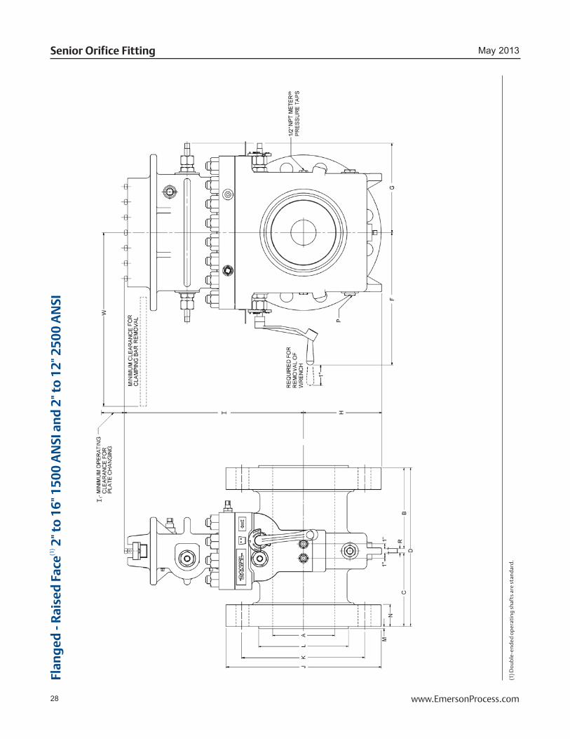
28 www.EmersonProcess.com
May 2013Senior Orifice Fitting
Flan
ged
- R
aise
d F
ace(1
) 2" t
o 1
6" 1
500
AN
SI a
nd
2" t
o 1
2" 2
500
AN
SI
(1) D
oub
le-e
nded
op
erat
ing
shaf
ts a
re s
tand
ard.

29www.EmersonProcess.com
Technical GuideDifferential Pressure Flow Meters
Standard Trim(2)
Diameter Internal Line Bore
Upstream Face of Orifice Plate to Face of End
Downstream Face of Orifice Plate to Face of End
Overall Face to Face
Operating Clearance from Center
Body Clearance from Center
Clearance to Bottom
Centerline to Top
Clearance for Plate Changing
Diameter of Flange
Diameter of Bolt Circle
Diameter of Raised Face +.000 -.005
Height of Raised Face
Flange Thickness
Number of Bolts / Studs per Flange
Diameter of Flange Bolts / Studs
Length of Bolts / Studs with 2 Hex Nuts
Size of Drain Plugs(1)
Orifice Plate Thickness
Weight (lb)
Minimum Clearance for Clamping Bar Removal
SIZE
AB
CD
FG
HI
I1J
KL
MN
PR
W
Cat
alo
g N
o. 1
07-D
anie
l 2-1
6" F
lan
ged
-Rai
sed
Fac
e 15
00 A
NSI
(use
PTF
E Se
al R
ing
or
SSR
on
ly)
A2"
*6
15/
166
15/
1614
13
75
146
8 1
/2
6 1
/2
3 5
/8
1/4
1
1/2
8
7/8
5
3/4
1
/2
1/8
23
011
A3"
*8
3/1
67
11/
1616
14
86
157
10 1
/2
8 5
1/4
1
7/8
8
1 1
/8
7 1
/2
1/8
27
513
A4"
*8
3/8
7
7/8
16
3/8
16
107
178
12 1
/4
9 1
/2
6 3
/16
1/4
2
1/8
8
1 1
/4
7 3
/4
3/4
1
/8
520
16A
6"*
10 3
/4
10 3
/16
21 1
/16
1610
820
1015
1/2
12
1/2
8
1/2
1
/4
3 1
/4
121
3/8
10
1/4
3
/4
1/8
87
520
A8"
*11
23/
3211
5/3
223
1/8
18
1210
2312
19
15 1
/2
10 5
/8
1/4
3
5/8
12
1 5
/8
11 1
/2
3/4
1
/4
1,50
022
A10
"*
12 5
/16
12 5
/16
24 7
/8
1913
1226
1423
19
12
3/4
1
/4
4 1
/4
121
7/8
13
1/2
3
/4
1/4
2,
180
26A
12"
*13
5/1
613
5/1
626
7/8
23
1714
2916
26 1
/2
22 1
/2
15
1/4
4
7/8
16
2 14
3/4
3
/4
1/4
3,
470
30A
14"
*10
15/
1615
13/
1627
1/8
27
2117
3518
29 1
/2
25
16 1
/4
1/4
5
1/4
16
2 1
/4
16
3/4
1
/4
CF
31A
16"
*16
7/1
616
11/
1633
3/4
28
2217
3620
32 1
/2
27 3
/4
18 1
/2
1/4
5
3/4
16
2 1
/2
17 1
/2
3/4
3
/8
CF
36
Cat
alo
g N
o. 1
08-D
anie
l 2-1
2" F
lan
ged
-Rai
sed
Fac
e 25
00 A
NSI
(use
SN
C o
nly
)A
2"*
8 5
/8
8 5
/8
17 3
/8
1610
617
89
1/4
6 3
/4
3 5
/8
1/4
2
81
7 1
/2
1/8
56
013
A3"
*9
9/1
69
9/1
619
1/4
16
106
178
12
9 5
1/4
2
5/8
8
1 1
/4
8 3
/4
1/2
1
/8
660
13A
4"*
10 1
/2
10 1
/2
21 1
/8
1711
717
814
10
3/4
6
3/1
6 1
/4
3 8
1 1
/2
10
3/4
1
/8
840
15A
6"*
12 1
/2
12 1
/2
25 1
/8
1812
1020
1019
14
1/2
8
1/2
1
/4
4 1
/4
82
13 3
/4
3/4
1
/8
1,52
020
A8"
*19
9/
1619
9/1
639
3/8
26
2011
3920
21 3
/4
17 1
/4
10 5
/8
1/4
5
122
15
3/4
1
/4
16A
10"
*22
5/
8 22
5/8
45
1/2
27
2114
4121
26 1
/2
21 1
/4
12 3
/4
1/4
6
1/2
12
2 1
/2
19 1
/4
3/4
1
/4
17A
12"
*23
3/
8 23
3/8
47
27
2115
4121
30
24 3
/8
15
1/4
7
1/4
12
2 3
/4
21 1
/4
3/4
1
/4
17
(1
) Fla
nged
pro
cess
con
nect
ions
ava
ilabl
e.
(2) P
leas
e co
nsul
t Dan
iel f
acto
ry o
r rep
rese
ntat
ive
for o
ther
trim
s av
aila
ble
for s
ever
e se
rvic
e an
d ot
her c
ode
requ
irem
ents
, inc
ludi
ng lo
w-t
empe
ratu
re, h
igh
H2S,
Hig
h C
O2, N
OR
SOK
, ISO
516
7, P
ED, D
anie
l “A
ASG
”,
and
spec
ial a
pplic
atio
ns.
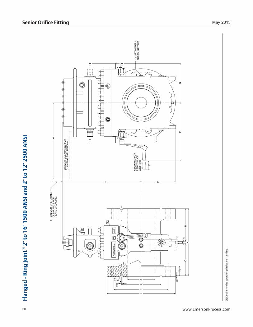
30 www.EmersonProcess.com
May 2013Senior Orifice Fitting
Flan
ged
- R
ing
Join
t(1) 2
" to
16"
150
0 A
NSI
an
d 2
" to
12"
250
0 A
NSI
(1) D
oub
le-e
nded
op
erat
ing
shaf
ts a
re s
tand
ard.
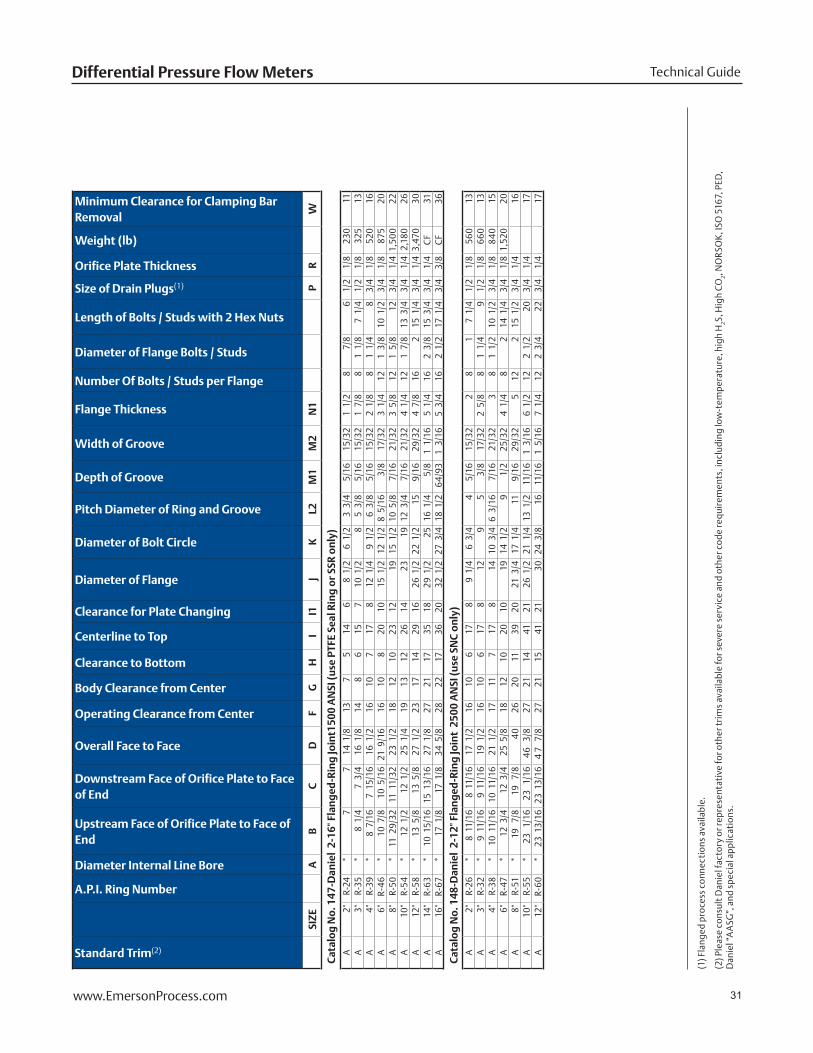
31www.EmersonProcess.com
Technical GuideDifferential Pressure Flow Meters
Standard Trim(2)
A.P.I. Ring Number
Diameter Internal Line Bore
Upstream Face of Orifice Plate to Face of End
Downstream Face of Orifice Plate to Face of End
Overall Face to Face
Operating Clearance from Center
Body Clearance from Center
Clearance to Bottom
Centerline to Top
Clearance for Plate Changing
Diameter of Flange
Diameter of Bolt Circle
Pitch Diameter of Ring and Groove
Depth of Groove
Width of Groove
Flange Thickness
Number Of Bolts / Studs per Flange
Diameter of Flange Bolts / Studs
Length of Bolts / Studs with 2 Hex Nuts
Size of Drain Plugs(1)
Orifice Plate Thickness
Weight (lb)
Minimum Clearance for Clamping Bar Removal
SIZE
AB
CD
FG
HI
I1J
KL2
M1
M2
N1
PR
W
Cat
alo
g N
o. 1
47-D
anie
l 2-
16" F
lan
ged
-Rin
g Jo
int1
500
AN
SI (u
se P
TFE
Seal
Rin
g o
r SS
R o
nly
)A
2"R-
24*
7 7
14 1
/8
137
514
68
1/2
6
1/2
3
3/4
5
/16
15/
321
1/2
8
7/8
6
1/2
1
/8
230
11A
3"R-
35*
8 1
/4
7 3
/4
16 1
/8
148
615
710
1/2
8
5 3
/8
5/1
6 1
5/32
1 7
/8
81
1/8
7
1/4
1
/2
1/8
32
513
A4"
R-39
*8
7/1
67
15/
1616
1/2
16
107
178
12 1
/4
9 1
/2
6 3
/8
5/1
6 1
5/32
2 1
/8
81
1/4
8
3/4
1
/8
520
16A
6"R-
46*
10 7
/8
10 5
/16
21 9
/16
1610
820
1015
1/2
12
1/2
8
5/1
6 3
/8
17/
323
1/4
12
1 3
/8
10 1
/2
3/4
1
/8
875
20A
8"R-
50*
11 2
9/32
11 1
1/32
23 1
/2
1812
1023
1219
15
1/2
10
5/8
7
/16
21/
323
5/8
12
1 5
/8
12
3/4
1
/4 1
,50
022
A10
"R-
54*
12 1
/2
12 1
/2
25 1
/4
1913
1226
1423
19
12
3/4
7
/16
21/
324
1/4
12
1 7
/8
13 3
/4
3/4
1
/4 2
,180
26A
12"
R-58
*13
5/8
13
5/8
27
1/2
23
1714
2916
26 1
/2
22 1
/2
15
9/1
6 2
9/32
4 7
/8
162
15 1
/4
3/4
1
/4 3
,470
30A
14"
R-63
*10
15/
1615
13/
1627
1/8
27
2117
3518
29 1
/2
25
16 1
/4
5/8
1
1/1
65
1/4
16
2 3
/8
15 3
/4
3/4
1
/4
CF
31A
16"
R-67
*17
1/8
17
1/8
34
5/8
28
2217
3620
32 1
/2
27 3
/4
18 1
/2
64/
931
3/1
65
3/4
16
2 1
/2
17 1
/4
3/4
3
/8
CF
36
Cat
alo
g N
o. 1
48-D
anie
l 2-
12" F
lan
ged
-Rin
g Jo
int
250
0 A
NSI
(use
SN
C o
nly
)A
2"R-
26*
8 1
1/16
8 1
1/16
17 1
/2
1610
617
89
1/4
6
3/4
4
5/1
6 1
5/32
2 8
1 7
1/4
1
/2
1/8
56
013
A3"
R-32
*9
11/
169
11/
1619
1/2
16
106
178
12
9 5
3/8
1
7/32
2 5
/8
81
1/4
9
1/2
1
/8
660
13A
4"R-
38*
10 1
1/16
10 1
1/16
21 1
/2
1711
717
814
10
3/4
6
3/1
6 7
/16
21/
323
81
1/2
10
1/2
3
/4
1/8
84
015
A6"
R-47
*12
3/4
12
3/4
25
5/8
18
1210
2010
19
14 1
/2
9 1
/2
25/
324
1/4
8
2 14
1/4
3
/4
1/8
1,5
2020
A8"
R-51
*19
7/
8 19
7/
8 40
26
2011
3920
21 3
/4
17 1
/4
11
9/1
6 2
9/32
5 12
2 15
1/2
3
/4
1/4
16
A10
"R-
55*
23
1/16
23
1/16
46
3/8
2721
1441
2126
1/2
21
1/4
13
1/2
1
1/16
1 3
/16
6 1
/2
122
1/2
20
3
/4
1/4
17
A12
"R-
60*
23 1
3/16
23 1
3/16
4 7
7/8
27
2115
4121
30
24 3
/8
16
11/
161
5/1
67
1/4
12
2 3
/4
22
3/4
1
/4
17
(1
) Fla
nged
pro
cess
con
nect
ions
ava
ilabl
e.
(2) P
leas
e co
nsul
t Dan
iel f
acto
ry o
r rep
rese
ntat
ive
for o
ther
trim
s av
aila
ble
for s
ever
e se
rvic
e an
d ot
her c
ode
requ
irem
ents
, inc
ludi
ng lo
w-t
empe
ratu
re, h
igh
H2S,
Hig
h C
O2, N
OR
SOK
, ISO
516
7, P
ED,
Dan
iel “
AA
SG”,
and
spe
cial
app
licat
ions
.

32 www.EmersonProcess.com
May 2013Senior Orifice Fitting
DanielTM SeniorTM Orifice Fitting Selection Matrix
6
BASIC TYPE / PRIMARY FUNCTIONNominal line size 6"Internal diameter 6.065
Fitting StyleRaised Face Flangnek 01Raised Face Flanged 10Ring Joint Flangnek 014Ring Joint Flanged 14
ANSI150# 1300# 3600# 5900# 61500# 72500# 8
Orifice Plate SealsRemovable Dual Seal*(up to 12") DSCDual Volcanized Seal*(16" and up) 3DVSRemovable PTFE Seal (up to 24") TSCRemovable Metal Seal (up to 24") MSCRemovable Snap Seal*(up to 20") SNC
Internal trim materialStandard ASour Gas / Corrosive Service AASGNACE (standard 2" to 8") 150 - 600 ANSI NACE
When ordering, please specify: Catalog Number, Plate Material, Plate Bore(s) and Quantity.
Note: All products and components are subject to change without notice in a continuing effort of product improvement.


©2013 Daniel Measurement and Control, Inc. All Rights Reserved. Unauthorized duplication in whole or in part is prohibited. Printed in the USA. DAN-SOF-TECH-GUIDE-0513
Daniel Measurement and Control, Inc. (“Daniel”) is an Emerson Process Management business unit. The Daniel name and logo are trademarks of Daniel Industries, Inc. The Emerson logo is a trademark and service mark of Emerson Electric Co. Parker is a trademark of Parker Hannifin Corporation.
Emerson Process Management
Daniel Measurement and Control, Inc. North America / Latin America: Headquarters USA - Houston, Texas T +1.713.467.6000 USA Toll Free 1.888.FLOW.001
www.Daniel.com
Europe: Stirling, Scotland, UK T +44.1786.433400 Middle East, Africa: Dubai, UAE T +971.4.811.8100 Asia Pacific: Singapore T +65.6777.8211
Scan with your smart phone for more information