Embed Size (px)
Citation preview

246646-YTG-E-1006
FOR DISTRIBUTION USE ONLY - NOT TO B
HIGH EFFICIENCY
SINGLE PACKAGE AIR CONDITIONERS AND
SINGLE PACKAGE GAS/ELECTRIC UNITSDH 078, 090, 102, 120 and 150
6-1/2, 7-1/2, 8-1/2, 10 and 12-1/2 NOMINAL TONS
10.0-11.5 EER
TECHNICALGUIDE TECHNICALGUIDE
�
� �
DESCRIPTIONASHRAE 90.1 COMPLIANT
YORK® Predator® units are convertible single packages with a common footprint cabinet and common roof curb for all 6-1/2 through 12-1/2 ton models. All units have two compressors with independent refrigeration circuits to provide 2 stages of cooling. The units were designed for light commercial applications and can be easily installed on a roof curb, slab, or frame.
All Predator® units are self-contained and assembled on rigid full perimeter base rails allowing for 3-way forklift access and overhead rigging. Every unit is completely charged, wired, piped, and tested at the factory to provide a quick and easy field installation.
All units are convertible between side and down airflow. Inde-pendent economizer designs are used on side and down dis-charge applications, as well as all tonnage sizes.
Predator® units are available in the following configurations: cooling only, cooling with electric heat, and cooling with gas heat. Electric heaters are available as factory-installed options or field-installed accessories.
Tested in accordance with:
E USED AT POINT OF RETAIL SALE

246646-YTG-E-1006
TABLE OF CONTENTSDESCRIPTION . . . . . . . . . . . . . . . . . . . . . . . . . . . . . . . . . . . 1FEATURES . . . . . . . . . . . . . . . . . . . . . . . . . . . . . . . . . . . . . 3FACTORY INSTALLED OPTIONS . . . . . . . . . . . . . . . . . . . 5FIELD INSTALLED ACCESSORIES . . . . . . . . . . . . . . . . . 6NOMENCLATURE . . . . . . . . . . . . . . . . . . . . . . . . . . . . . . . 10GUIDE SPECIFICATIONS . . . . . . . . . . . . . . . . . . . . . . . . . 46
LIST OF FIGURES
Fig. # Pg. #
1 PREDATOR® COMPONENT LOCATION(DH120 SHOWN) . . . . . . . . . . . . . . . . . . . . . . . . . . . . . . . 3
2 UNIT 4 POINT LOAD . . . . . . . . . . . . . . . . . . . . . . . . . . . 353 UNIT CENTER OF GRAVITY . . . . . . . . . . . . . . . . . . . . . 354 UNIT 6 POINT LOAD . . . . . . . . . . . . . . . . . . . . . . . . . . . 355 UNIT DIMENSIONS . . . . . . . . . . . . . . . . . . . . . . . . . . . . 366 PREDATOR® ROOF CURB DIMENSIONS . . . . . . . . . . 377 SUNLINE™ TO PREDATOR® TRANSITION ROOF
CURBS . . . . . . . . . . . . . . . . . . . . . . . . . . . . . . . . . . . . . . 378 BOTTOM DUCT OPENINGS . . . . . . . . . . . . . . . . . . . . . . 389 REAR DUCT DIMENSIONS . . . . . . . . . . . . . . . . . . . . . . 3810 DOWNFLOW ECONOMIZER HOOD DETAIL . . . . . . . . 3911 FACTORY INSTALLED DOWNFLOW ECONOMIZER . . 4012 FIELD INSTALLED DOWNFLOW ECONOMIZER W/
POWER EXHAUST . . . . . . . . . . . . . . . . . . . . . . . . . . . . . 4013 FIELD INSTALLED HORIZONTAL ECONOMIZER W/
POWER EXHAUST . . . . . . . . . . . . . . . . . . . . . . . . . . . . . 4114 SLAB ECONOMIZER DOWNFLOW W/POWER
EXHAUST . . . . . . . . . . . . . . . . . . . . . . . . . . . . . . . . . . . . 4115 SLAB ECONOMIZER END RETURN W/POWER
EXHAUST . . . . . . . . . . . . . . . . . . . . . . . . . . . . . . . . . . . . 4216 COOLING UNIT WITH GAS HEAT WIRING 230 VOLT
DIAGRAM . . . . . . . . . . . . . . . . . . . . . . . . . . . . . . . . . . . . 4317 COOLING UNIT WITH/WITHOUT ELECTRIC HEAT
WIRING DIAGRAM . . . . . . . . . . . . . . . . . . . . . . . . . . . . . 4418 COOLING UNIT WITH GAS HEAT WIRING 460, 575 VOLT
50 HZ DIAGRAM . . . . . . . . . . . . . . . . . . . . . . . . . . . . . . . 45
LIST OF TABLES
Tbl. # Pg. #
1 ACCESSORIES . . . . . . . . . . . . . . . . . . . . . . . . . . . . . . . . . 82 DH PHYSICAL DATA . . . . . . . . . . . . . . . . . . . . . . . . . . . 113 DH CAPACITY RATINGS . . . . . . . . . . . . . . . . . . . . . . . . 124 UNIT VOLTAGE LIMITATIONS . . . . . . . . . . . . . . . . . . . . 125 COOLING CAPACITY DH078 (6-1/2 TON) UNIT . . . . . . 136 COOLING CAPACITY DH090 (7-1/2 TON) UNIT . . . . . . 147 COOLING CAPACITY DH102 (8-1/2 TON) UNIT . . . . . . 158 COOLING CAPACITY DH120 (10 TON) UNIT . . . . . . . . 169 COOLING CAPACITY DH150 (12-1/2 TON) UNIT . . . . . 1710 ELECTRICAL DATA DH078 (6-1/2 TON) HIGH
EFFICIENCY W/O PWRD CONVENIENCE OUTLET . . . 18
Tbl. # Pg. #
11 ELECTRICAL DATA DH078 (6-1/2 TON) HIGH EFFICIENCY WITH PWRD CONVENIENCE OUTLET . 18
12 ELECTRICAL DATA DH090 (7-1/2 TON) HIGH EFFICIENCY W/O PWRD CONVENIENCE OUTLET . . 19
13 ELECTRICAL DATA DH090 (7-1/2 TON) HIGH EFFICIENCY WITH PWRD CONVENIENCE OUTLET . 19
14 ELECTRICAL DATA DH102 (8-1/2 TON) HIGH EFFICIENCY W/O PWRD CONVENIENCE OUTLET . . 20
15 ELECTRICAL DATA DH102 (8-1/2 TON) HIGH EFFICIENCY WITH PWRD CONVENIENCE OUTLET . 20
16 ELECTRICAL DATA DH120 (10 TON) HIGH EFFICIENCY W/O PWRD CONVENIENCE OUTLET . . . . . . . . . . . . . 21
17 ELECTRICAL DATA DH120 (10 TON) HIGH EFFICIENCY WITH PWRD CONVENIENCE OUTLET . . . . . . . . . . . . 21
18 ELECTRICAL DATA DH150 (12-1/2 TON) HIGH EFFICIENCY W/O PWRD CONVENIENCE OUTLET . . 22
19 ELECTRICAL DATA DH150 (12-1/2 TON) HIGH EFFICIENCY W/PWRD CONVENIENCE OUTLET . . . . 22
20 ELECTRIC HEAT MULTIPLIERS . . . . . . . . . . . . . . . . . . 2221 DH078 (6-1/2) SIDE SHOT BLOWER
PERFORMANCE . . . . . . . . . . . . . . . . . . . . . . . . . . . . . . 2322 DH090 (7-1/2 TON) SIDE SHOT BLOWER
PERFORMANCE . . . . . . . . . . . . . . . . . . . . . . . . . . . . . . 2423 DH102 (8-1/2 TON) SIDE SHOT BLOWER
PERFORMANCE . . . . . . . . . . . . . . . . . . . . . . . . . . . . . . 2524 DH120 (10 TON) SIDE SHOT BLOWER
PERFORMANCE . . . . . . . . . . . . . . . . . . . . . . . . . . . . . . 2625 DH150 (12-1/2 TON) SIDE SHOT BLOWER
PERFORMANCE . . . . . . . . . . . . . . . . . . . . . . . . . . . . . . 2726 DH078 (6-1/2 TON) DOWN SHOT BLOWER
PERFORMANCE . . . . . . . . . . . . . . . . . . . . . . . . . . . . . . 2827 DH090 (7-1/2 TON) DOWN SHOT BLOWER
PERFORMANCE . . . . . . . . . . . . . . . . . . . . . . . . . . . . . . 2928 DH102 (8-1/2 TON) DOWN SHOT BLOWER
PERFORMANCE . . . . . . . . . . . . . . . . . . . . . . . . . . . . . . 3029 DH120 (10 TON) DOWN SHOT BLOWER
PERFORMANCE . . . . . . . . . . . . . . . . . . . . . . . . . . . . . . 3130 DH150 (12-1/2 TON) DOWN SHOT BLOWER
PERFORMANCE . . . . . . . . . . . . . . . . . . . . . . . . . . . . . . 3231 ADDITIONAL STATIC RESISTANCE DH120 AND 150 . 3332 ADDITIONAL STATIC RESISTANCE DH078, 090, 102 . 3333 ELECTRIC HEAT MINIMUM SUPPLY AIR CFM . . . . . . 3434 INDOOR BLOWER SPECIFICATIONS . . . . . . . . . . . . . 3435 POWER EXHAUST SPECIFICATIONS . . . . . . . . . . . . . 3436 4 POINT LOAD WEIGHT . . . . . . . . . . . . . . . . . . . . . . . . 3537 6 POINT LOAD WEIGHT . . . . . . . . . . . . . . . . . . . . . . . . 3538 UNIT WEIGHT . . . . . . . . . . . . . . . . . . . . . . . . . . . . . . . . 3539 UNIT HEIGHT . . . . . . . . . . . . . . . . . . . . . . . . . . . . . . . . . 3640 UNIT CLEARANCES . . . . . . . . . . . . . . . . . . . . . . . . . . . 3641 ECONOMIZER USAGE . . . . . . . . . . . . . . . . . . . . . . . . . 39
2 Unitary Products Group
246646-YTG-E-1006
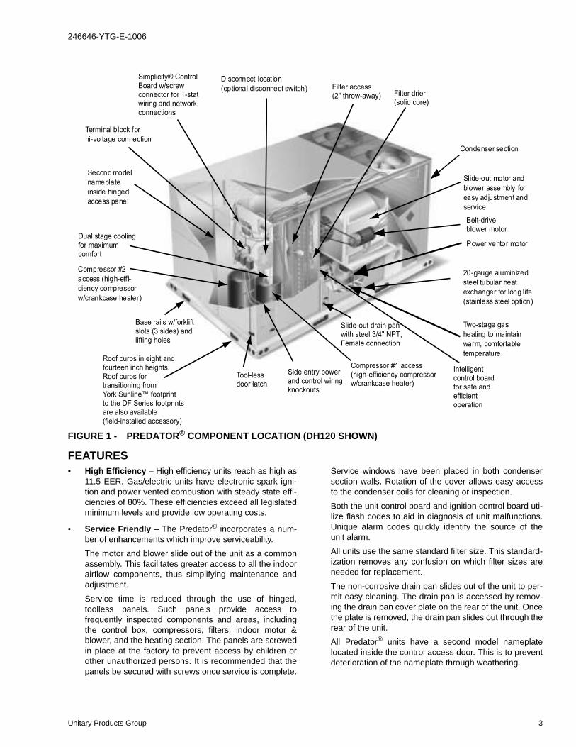
FEATURES• High Efficiency – High efficiency units reach as high as
11.5 EER. Gas/electric units have electronic spark igni-tion and power vented combustion with steady state effi-ciencies of 80%. These efficiencies exceed all legislatedminimum levels and provide low operating costs.
• Service Friendly – The Predator® incorporates a num-ber of enhancements which improve serviceability.
The motor and blower slide out of the unit as a commonassembly. This facilitates greater access to all the indoorairflow components, thus simplifying maintenance andadjustment.
Service time is reduced through the use of hinged,toolless panels. Such panels provide access tofrequently inspected components and areas, includingthe control box, compressors, filters, indoor motor &blower, and the heating section. The panels are screwedin place at the factory to prevent access by children orother unauthorized persons. It is recommended that thepanels be secured with screws once service is complete.
Service windows have been placed in both condensersection walls. Rotation of the cover allows easy accessto the condenser coils for cleaning or inspection.
Both the unit control board and ignition control board uti-lize flash codes to aid in diagnosis of unit malfunctions.Unique alarm codes quickly identify the source of theunit alarm.
All units use the same standard filter size. This standard-ization removes any confusion on which filter sizes areneeded for replacement.
The non-corrosive drain pan slides out of the unit to per-mit easy cleaning. The drain pan is accessed by remov-ing the drain pan cover plate on the rear of the unit. Oncethe plate is removed, the drain pan slides out through therear of the unit.
All Predator® units have a second model nameplatelocated inside the control access door. This is to preventdeterioration of the nameplate through weathering.
FIGURE 1 - PREDATOR® COMPONENT LOCATION (DH120 SHOWN)
Unitary Products Group 3

246646-YTG-E-1006
• Environmentally Aware – For improved Indoor AirQuality, foil faced insulation is used exclusively through-out the units.
• Balanced Heating – The Predator® offers “Ultimate Heat-ing Comfort” with a balance between 1st and 2nd stagegas heating. The first stage of a gas heat Predator® unitprovides 60% of the heating capacity. Balanced heatingallows the unit to better maintain desired temperatures.
• Convertible Airflow Design – The side duct openingsare covered when they leave the factory. If a side supply/return is desired, the installer simply removes the twoside duct covers from the outside of the unit and installsthem over the down shot openings. No panel cutting isrequired. Convertible airflow design allows maximumfield flexibility and minimum inventory.
• System Protection - Suction line freezestats are supplied on all units to protect against loss of charge and coil frost-ing when the economizer operates at low outdoor air tem-peratures while the compressors are running. Every unit has solid-core liquid line filter-driers and high and low-pressure switches. Internal compressor protection is stan-dard on all compressors. Crankcase heaters are standard on reciprocating compressors. Scroll compressors do not require crankcase heaters. Phase Monitors are standard on units with scroll compressors. This accessory monitors the incoming power to the unit and protects the unit from phase loss and reversed phase rotation.
• Advanced Controls - Simplicity™ control boards havestandardized a number of features previously availableonly as options or by utilizing additional controls.• Low Ambient - An integrated low-ambient control
allows all units to operate in the cooling mode downto 0°F outdoor ambient without additional assistance.Optionally, the control board can be programmed tolockout the compressors when the outdoor air tem-perature is low or when free cooling is available.
• Anti-Short Cycle Protection - To aid compressorlife, an anti-short cycle delay is incorporated into thestandard controls. Compressor reliability is furtherensured by programmable minimum run times. Fortesting, the anti-short cycle delay can be temporarilyoverridden with the push of a button.
• Fan Delays - Fan on and fan off delays are fully pro-grammable. Furthermore, the heating and coolingfan delay times are independent of one another. Allunits are programmed with default values basedupon their configuration of cooling and heat.
• Safety Monitoring - The control board monitors thehigh and low-pressure switches, the freezestats, thegas valve, if applicable, and the temperature limitswitch on gas and electric heat units. The unit con-trol board will alarm on ignition failures, compressorlockouts and repeated limit switch trips.
• Nuisance Trip Protection and Strikes - To preventnuisance trouble calls, the control board uses a“three times, you’re out” philosophy. The high and
low-pressure switches and the freezestats must tripthree times within two hours before the unit controlboard will lock out the associated compressor.
• On Board Diagnostics - Each alarm will energize atrouble light on the thermostat, if so equipped, andflash an alarm code on the control board LED. Eachhigh and low-pressure switch alarm as well as eachfreezestat alarm has its own flash code. The controlboard saves the five most recent alarms in memory,and these alarms can be reviewed at any time.Alarms and programmed values are retainedthrough the loss of power.
• Reliable – From the beginning – All units undergo com-puter automated testing before they leave the factory.Units are tested for refrigerant charge and pressure, unitamperage, and 100% functionality. For the long term –All Predator® units are painted with a long lasting, pow-der paint that stands up over the life of the unit. The paintused has been proven by a 1000 hour salt spray test.
• Flexible Placement – All models and configurationsshare the same cabinet/footprint and thus the same roofcurb. You have the flexibility to set one curb and choosethe correct tonnage size and heating option after theinternal loads have been determined.To further simplify planning and installation, Predator®
cabinets are designed to fit your roof. With the optionalroof curb, the unit ductwork is designed to fit around 24”on-center joists or between 48” on-center joists.The drain pan can be rotated to drain to either the frontor the rear of the unit. Additionally, the drain pan can befitted to drain through the roof curb. As it is sometimesdifficult to have a level installation, the drain pan featuresa generous slope to ensure proper drainage.
• Full Perimeter Base Rails – The permanently attachedbase rails provide a solid foundation for the entire unit andprotect the unit during shipment. The rails offer forkliftaccess from 3 sides, and rigging holes are available so thatan overhead crane can be used to place the units on a roof.
• Easy Installation – Gas and electric utility knockouts aresupplied in the unit underside as well as the side of the unit.A clearly identified location is provided to mount a field sup-plied electrical disconnect switch. Utility connections can bemade quickly and with a minimum amount of field labor.All units are shipped with 2” throw-away filters installed.
• Wide Range of Indoor Airflows – All indoor fan motorsare belt-drive type providing maximum flexibility to han-dle most airflow requirements. For high static applica-tions, factory installed alternate indoor fan motors areavailable. With the optional indoor fan motor, all units cansupply nominal airflow at a minimum of 1.5” ESP.
• Warranty - All models include a 1-year limited warrantyon the complete unit. Compressors and electric heaterelements each carry a 5-year warranty. Aluminized steeland stainless steel tubular heat exchangers carry a 10-year warranty.
4 Unitary Products Group

246646-YTG-E-1006
FACTORY INSTALLED OPTIONSYORK® offers several equipment options factory installed, for the Predator® line.
• Optional Factory Installed Economizers - Predator unitsoffer a variety of optional factory installed economizers withlow leak dampers. The outdoor air enthalpy sensor enableseconomizer operation if the outdoor enthalpy is less thanthe setpoint of the economizer logic module. See Table 41to determine the correct economizer for your application.• Downflow Economizer - (With barometric relief) -
The economizer is provided with a single enthalpyinput. The economizer is 2% low leakage type, and isshipped installed and wired. The installer needs onlyto assemble and mount the outdoor air hood (Pro-vided). The economizer has spring return, fully modu-lating damper actuators and is capable of introducingup to 100% outdoor air. As the outdoor air intakedampers open, the return air dampers close. Thechangeover from mechanical refrigeration to econo-mizer operation is regulated by the standard singleenthalpy input. There is an optional input dual drybulb available. To meet regulated air standards, theeconomizer control accepts an optional CO2 input fordemand ventilation. With single enthalpy input, theeconomizer control monitors outdoor air. The dualenthalpy kit provides a second input used to monitorthe return air. With a dual input kit installed, the econ-omizer control compares the values of the twoenthalpy or temperature inputs and positions thedampers to provide the maximum efficiency possible.
• Horizontal Economizer - (Without barometricrelief) - All features of the downflow economizerexist except you must order the duct mount baro-metric relief separately. You must order a 1EH0408if you are installing a power exhaust. You canorder a 1RD0411 Barometric Relief for horizontalflow economizers only.
• BAS Ready Economizer -(With barometric relief) -The economizer is provided with a Belimo actuatorthat requires a 0-10V DC input from an externalsource (i.e., field installed building automation systemcontroller). Power exhaust options are available. Theeconomizer is 2% low leakage type with spring returnand fully modulating dampers capable of introducingup to 100% outside air. Also include 2” pleated filters.
• Slab Economizer for Energy Recovery Ventilators-(With barometric relief and Fresh Air Hood) - Theeconomizer is provided with a single enthalpy input.The economizer is 2% low leakage type, and isshipped installed and wired. The economizer hasspring return, fully modulating damper actuators and iscapable of introducing up to 100% outdoor air. As theoutdoor air intake dampers open, the return air damp-ers close. The changeover from mechanical refrigera-tion to economizer operation is regulated by thestandard single enthalpy input. There is an optionalinput dual dry bulb available. To meet regulated airstandards, the economizer control accepts an optionalCO2 input for demand ventilation.With single enthalpy
input, the economizer control monitors outdoor air. Thedual enthalpy kit provides a second input used to mon-itor the return air. With a dual input kit installed, theeconomizer control compares the values of the twoenthalpy or temperature inputs and positions thedampers to provide the maximum efficiency possible.
• Power Exhaust (Downflow only) - This accessory installs in the unit with a down flow economizer.
• Motorized Outdoor Air Damper - The motorized out-door air damper includes a slide-in/plug-in damper assembly with an outdoor air hood and filters. The out-door air dampers open to the preset position when the indoor fan motor is energized. The damper has a range of 0% to 100% outdoor air entry. Factory installed option or field installed accessory.
• Alternate Indoor Blower Motor - For applications with high static restrictions, units are offered with optional indoor motors that provide higher static output and/or higher airflow, depending upon the installer’s needs.
• Aluminized Steel Gas Heat Exchanger - For applica-tions in non-corrosive environments.
• Stainless Steel Gas Heat Exchanger - For applications in corrosive environments, this option provides a full stainless steel heat exchanger assembly.
• Stainless Steel Drain Pan - An optional rust-proof stain-less steel drain pan is available to provide years of trou-ble-free operation in corrosive environments.
• Electric Heaters - The electric heaters range from 9kW to 54kW and are available in all the voltage options of the base units. All heaters are dual staged. All heaters are intended for single point power supply.
• Disconnect Switch - For gas heat units and cooling units with electric heat, a HACR breaker sized to the unit is provided. For cooling only units, a switch sized to the largest electric heat available for the particular unit is provided. Factory installed option only.
• Convenience Outlet - (Non-Powered/Powered) - This option locates a 120V single-phase GFCI outlet with cover, on the corner of the unit housing adjacent to the compressors. The “Non-powered” option requires the installer to provide the 120V single-phase power source and wiring. The “Powered” option is powered by a step-down transformer in the unit. Factory installed option only.
• Smoke Detectors - The smoke detectors stop operation of the unit by interrupting power to the control board if smoke is detected within the air compartment. Available for both the supply and/or return air.
Factory installed smoke detectors in the return air,may be subjected to freezing temperatures during"off" times due to out side air infiltration. Thesesmoke detectors have an operational limit of 32 °Fto 131°F. Smoke detectors installed in areas thatcould be out side those limitations will have to bemoved to prevent having false alarms.
Unitary Products Group 5

246646-YTG-E-1006
• Phase Monitors - Designed to prevent unit damage. The phase monitor will shut the unit down in an out-of phase condition. (Standard on units with Scroll Compressors.)
• Coil Guard - Customers can purchase a coil guard kit to protect the condenser coil from damage. Additionally, this kit stops animals and foreign objects from entering the space between the inner condenser coil and the main cabinet. This is not a hail guard kit.
• Dirty Filter Switch - This kit includes a differential pres-sure switch that energizes the fault light on the unit ther-mostat, indicating that there is an abnormally high pressure drop across the filters. Factory installed option or field installed accessory.
• Technicoat Condenser Coils - The condenser coils are coated with a phenolic coating for protection against cor-rosion due to harsh environments.
• Technicoat Evaporator Coil - The evaporator coils are coated with a phenolic coating for protection against cor-rosion due to harsh environments.
• BAS - Building Automation System Controls Simplic-ity™ INTELLI-Comfort™ Control - The York® Simplic-ity™ INTELLI-Comfort™ control is factory installed. Itincludes a supply air sensor, a return air sensor, and anoutside air sensor. There are provisions for a fieldinstalled dirty filter indicator switch, an air-proving switch,an Outside Air Humidity sensor, a Return Air Humiditysensor, an Inside IAQ sensor, and an Outside Air IAQsensor. Construction mode operation, 365-day real timeclock with 7 day programming plus holiday scheduling isbuilt-in. Two different modes of demand ventilation areachieved through the INTELLI-Comfort™ using CO2sensors. It uses an inside CO2 sensor to performDemand Ventilation. It can also use an Outside CO2 sen-sor to perform Differential Demand Ventilation. It uses aPatented Comfort Ventilation algorithm to provide com-fortable ventilation air temperature. The patented econo-mizer-loading algorithm will protect the equipment whenharsh operating conditions exist. Humidity in the occu-pied space or return duct can be monitored and con-trolled via humidity sensors and the on-board connectionfor hot gas re-heat system. It uses the INTELLI-Start™algorithm to maximize energy savings by recovering thebuilding from the Unoccupied Setpoints to the OccupiedSetpoints just in time for the Occupied Time Period tobegin. The Simplicity™ INTELLI-Comfort™ balancesspace temperature, ventilation air temperature, CO2 andhumidity for ultimate comfort.
• Simplicity™ INTELLI-Comfort™ with ModLINCControl - The York® Simplicity™ INTELLI-Comfort™with ModLINC control is factory installed. It includes allthe features of the INTELLI-Comfort™ control with anadditional control to translate communications fromMODBUS to the BACnet MSTP protocol.
• Novar® BAS Control - The Novar® ETC-3 buildingautomation system controller is factory installed. Incudes
supply air sensor, return air sensor, dirty filter indicatorswitch, and air proving switch.
• Johnson Controls BAS Control - The Johnson ControlYK-UNT-1126 building automation system controller isfactory installed. Includes supply air sensor, return airsensor, dirty filter indicator switch, and air proving switch.
• CPC BAS Control - The Computer Process ControlsModel 810-3060 ARTC Advanced Rooftop building auto-mation system controller is factory installed. Includessupply air sensor, return air sensor, dirty filter indicatorswitch and air proving switch.
• Honeywell BAS Control - The Honeywell W7750Cbuilding automation system controller is factory installed.Includes air supply sensor, return air sensor, dirty filterindicator switch, and air proving switch.
FIELD INSTALLED ACCESSORIESYORK® offers several equipment accessories for field instal-lation, for the Predator® line.
• Downflow Economizer - (With barometric relief) - The economizer is provided with a single enthalpy input. The economizer is 2% low leakage type. The economizer has spring return, fully modulating damper actuators and is capable of introducing up to 100% outdoor air. As the outdoor air intake dampers open, the return air dampers close. The changeover from mechanical refrigeration to economizer operation is regulated by the standard single enthalpy input. There is an optional input dual dry bulb available. To meet regulated air standards, the econo-mizer control accepts an optional CO2 input for demand ventilation. With single enthalpy input, the economizer control monitors outdoor air. The dual enthalpy kit pro-vides a second input used to monitor the return air. With a dual input kit installed, the economizer control com-pares the values of the two enthalpy or temperature inputs and positions the dampers to provide the maxi-mum efficiency possible
• Horizontal Economizer - (Without barometric relief) - All features of the downflow economizer exist except you must order the duct mount barometric relief separately. You must order a 1EH0408 if you are installing a power exhaust. You can order a 1RD0411 Barometric Relief for horizontal flow economizer.
• Slab Economizer for Energy Recovery Ventilator- (Without barometric relief or Fresh Air Hood) - The economizer is provided with a single enthalpy input. The economizer is 2% low leakage type. The economizer has spring return, fully modulating damper actuators and is capable of introducing up to 100% outdoor air. As the outdoor air intake dampers open, the return air dampers close. The changeover from mechanical refrigeration to economizer operation is regulated by the standard single enthalpy input. There is an optional input dual dry bulb available. To meet regulated air standards, the econo-mizer control accepts an optional CO2 input for demand
6 Unitary Products Group

246646-YTG-E-1006
ventilation.With single enthalpy input, the economizer control monitors outdoor air. The dual enthalpy kit pro-vides a second input used to monitor the return air. With a dual input kit installed, the economizer control com-pares the values of the two enthalpy or temperature inputs and positions the dampers to provide the maxi-mum efficiency possible.
You can order 1EH0409 Barometric Relief/FA Hoodfor field installations without an ERV.
• Dual Enthalpy Control, Accessory - This kit contains the required components to convert a single enthalpy economizer to dual enthalpy.
• Barometric Relief Damper - Zero to 100% capacity barometric relief dampers for use with horizontal flow, or field installed slab economizers.
• Power Exhaust - This accessory installs in the unit with a down flow economizer. Power exhaust plugs into the connector in the unit bulkhead. You must purchase 1EH0408 barometric relief when applying to a hori-zontal flow application.
• Manual Outdoor Air Damper - Like the motorized out-door air damper, each manual outdoor air damper includes a slide-in damper assembly with an outdoor air hood and filters. Customers have a choice of dampers with ranges of 0% to 100% or 0% to 35% outdoor air entry.
• Motorized Outdoor Air Damper - The motorized out-door air damper includes a slide-in/plug-in damper assembly with an outdoor air hood and filters. The out-door air dampers open to the preset position when the indoor fan motor is energized. The damper has a range of 0% to 100% outdoor air entry. Factory installed option or field installed accessory.
• Smoke Detectors - The smoke detectors stop operation of the unit by interrupting power to the control board if smoke is detected within the air compartment.
• CO2 Sensor - Senses CO2 levels and automatically overrides the economizer when levels rise above the preset limits.
• Dirty Filter Switch - This kit includes a differential pres-sure switch that energizes the fault light on the unit ther-mostat, indicating that there is an abnormally high pressure drop across the filters.
• Coil Guard - Field installed decorative wire coil guard.
• Hail Guard - This kit includes a sloped hood which installs over the outside condenser coil and prevents damage to the coil fins from hail strikes. Field installed accessory only.
• Flue Exhaust Extension Kit - In locations with wind or weather conditions which may interfere with proper exhausting of furnace combustion products, this kit can be installed to prevent the flue exhaust from entering nearby fresh air intakes.
• -60°F Gas Heat Kit - For installations which require gas heat units to perform in low ambient temperatures, a gas section heating kit is available. This kit provides electric heat in the gas heat controls section to ensure the gas valve and controls will continue to function properly at extremely low temperatures.
• Gas Heat High Altitude Kit - This kit converts a gas heat unit to operate at high altitudes, 2,000 to 6,000 feet. Conversion kits are available for natural gas and pro-pane.
• Gas Heat Propane Conversion Kit - This kit converts a gas-fired heater from natural gas to propane. It contains the main burner orifices and gas valve replacement springs.
• Gas Piping Kit - Contains pipe nipples, fittings and gas cock required for gas supply connection with external shut off.
• Electric Heaters - The electric heaters range from 9 kW to 54kW and are available in all the voltage options of the base units. All heaters are dual staged. Cooling units include an adapter panel for easy installation of the elec-tric heaters. Necessary hardware and connectors are included with the heaters. All heaters are intended for single point power supply.
• Low Limit / Compressor Lockout Kit
1. Compressor Lockout (CLO): To prevent mechani-cal (compressorized) operation of the unit during cold outdoor conditions where there is a risk of returning liquid refrigerant back to the compressors.
2. Low Limit Control (LLC): To prevent the supply air from dropping below a specified setpoint by utilizing the units first stage heating means when there is a demand for cooling during cold outside conditions.
• Metal Frame Filter Kit - Metal frame with polyester filter medium.
• Permanent Filters - Permanent filters are available.
• Roof Curbs - The roof curbs have insulated decks and are shipped disassembled The roof curbs are available in 8” and 14” heights. For applications with security con-cerns, burglar bars are available for the duct openings of the roof curbs.
• Roof Curb Transition - Single Piece Adapter (10” High) - Roof curbs for transitioning from Sunline™ units to Predator® units. Fits 7.5 to 12.5 Sunline™ roof curbs only.
• Burglar Bars - Mount in the supply and return openings to prevent entry into the duct work.
• Thermostat - The units are designed to operate with 24- volt electronic and electro-mechanical thermostats. All units (with or without an economizer) operate with two-stage heat/two-stage cool or two-stage cooling only ther-mostats, depending upon unit configuration.
Unitary Products Group 7
246646-YTG-E-1006
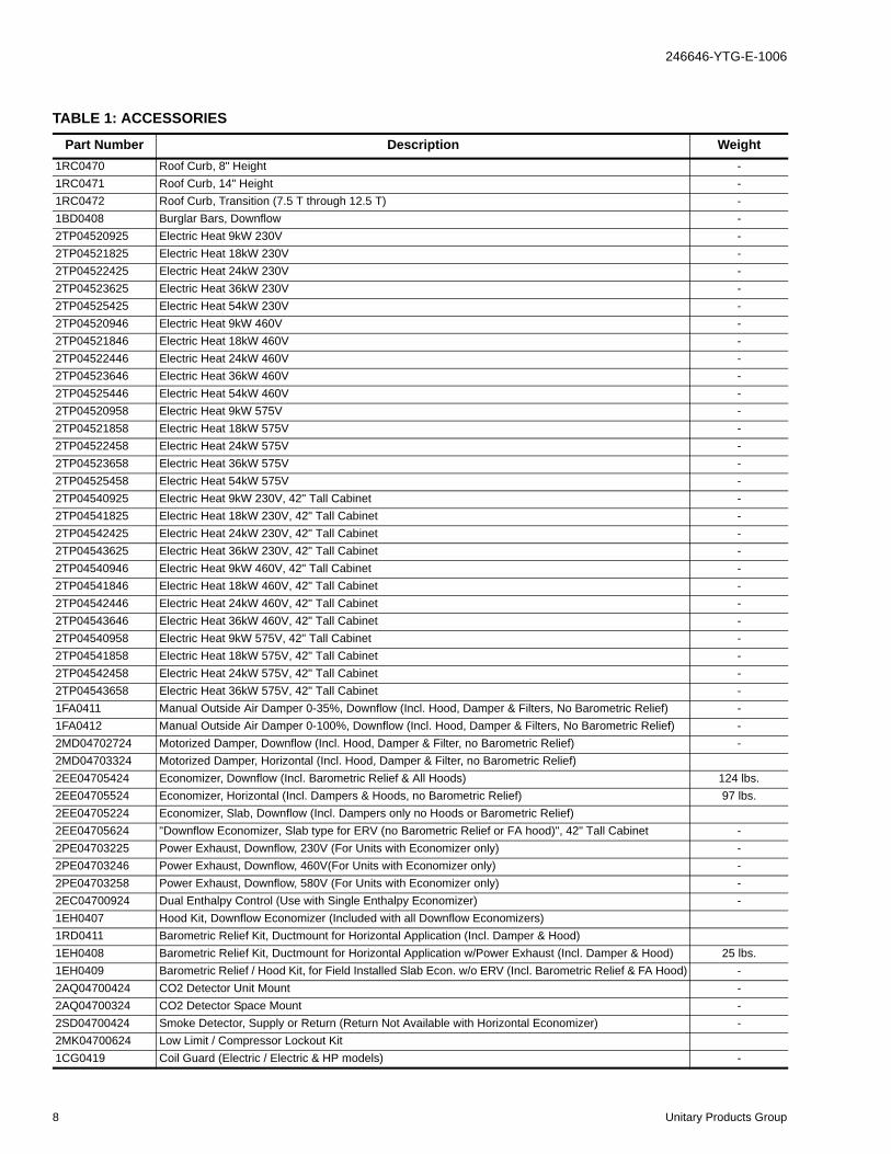
TABLE 1: ACCESSORIES
Part Number Description Weight1RC0470 Roof Curb, 8" Height -1RC0471 Roof Curb, 14" Height -1RC0472 Roof Curb, Transition (7.5 T through 12.5 T) -1BD0408 Burglar Bars, Downflow -2TP04520925 Electric Heat 9kW 230V -2TP04521825 Electric Heat 18kW 230V -2TP04522425 Electric Heat 24kW 230V -2TP04523625 Electric Heat 36kW 230V -2TP04525425 Electric Heat 54kW 230V -2TP04520946 Electric Heat 9kW 460V -2TP04521846 Electric Heat 18kW 460V -2TP04522446 Electric Heat 24kW 460V -2TP04523646 Electric Heat 36kW 460V -2TP04525446 Electric Heat 54kW 460V -2TP04520958 Electric Heat 9kW 575V -2TP04521858 Electric Heat 18kW 575V -2TP04522458 Electric Heat 24kW 575V -2TP04523658 Electric Heat 36kW 575V -2TP04525458 Electric Heat 54kW 575V -2TP04540925 Electric Heat 9kW 230V, 42" Tall Cabinet -2TP04541825 Electric Heat 18kW 230V, 42" Tall Cabinet -2TP04542425 Electric Heat 24kW 230V, 42" Tall Cabinet -2TP04543625 Electric Heat 36kW 230V, 42" Tall Cabinet -2TP04540946 Electric Heat 9kW 460V, 42" Tall Cabinet -2TP04541846 Electric Heat 18kW 460V, 42" Tall Cabinet -2TP04542446 Electric Heat 24kW 460V, 42" Tall Cabinet -2TP04543646 Electric Heat 36kW 460V, 42" Tall Cabinet -2TP04540958 Electric Heat 9kW 575V, 42" Tall Cabinet -2TP04541858 Electric Heat 18kW 575V, 42" Tall Cabinet -2TP04542458 Electric Heat 24kW 575V, 42" Tall Cabinet -2TP04543658 Electric Heat 36kW 575V, 42" Tall Cabinet -1FA0411 Manual Outside Air Damper 0-35%, Downflow (Incl. Hood, Damper & Filters, No Barometric Relief) -1FA0412 Manual Outside Air Damper 0-100%, Downflow (Incl. Hood, Damper & Filters, No Barometric Relief) -2MD04702724 Motorized Damper, Downflow (Incl. Hood, Damper & Filter, no Barometric Relief) -2MD04703324 Motorized Damper, Horizontal (Incl. Hood, Damper & Filter, no Barometric Relief)2EE04705424 Economizer, Downflow (Incl. Barometric Relief & All Hoods) 124 lbs.2EE04705524 Economizer, Horizontal (Incl. Dampers & Hoods, no Barometric Relief) 97 lbs.2EE04705224 Economizer, Slab, Downflow (Incl. Dampers only no Hoods or Barometric Relief)2EE04705624 "Downflow Economizer, Slab type for ERV (no Barometric Relief or FA hood)", 42" Tall Cabinet -2PE04703225 Power Exhaust, Downflow, 230V (For Units with Economizer only) -2PE04703246 Power Exhaust, Downflow, 460V(For Units with Economizer only) -2PE04703258 Power Exhaust, Downflow, 580V (For Units with Economizer only) -2EC04700924 Dual Enthalpy Control (Use with Single Enthalpy Economizer) -1EH0407 Hood Kit, Downflow Economizer (Included with all Downflow Economizers)1RD0411 Barometric Relief Kit, Ductmount for Horizontal Application (Incl. Damper & Hood)1EH0408 Barometric Relief Kit, Ductmount for Horizontal Application w/Power Exhaust (Incl. Damper & Hood) 25 lbs.1EH0409 Barometric Relief / Hood Kit, for Field Installed Slab Econ. w/o ERV (Incl. Barometric Relief & FA Hood) -2AQ04700424 CO2 Detector Unit Mount -2AQ04700324 CO2 Detector Space Mount -2SD04700424 Smoke Detector, Supply or Return (Return Not Available with Horizontal Economizer) -2MK04700624 Low Limit / Compressor Lockout Kit1CG0419 Coil Guard (Electric / Electric & HP models) -
8 Unitary Products Group
246646-YTG-E-1006
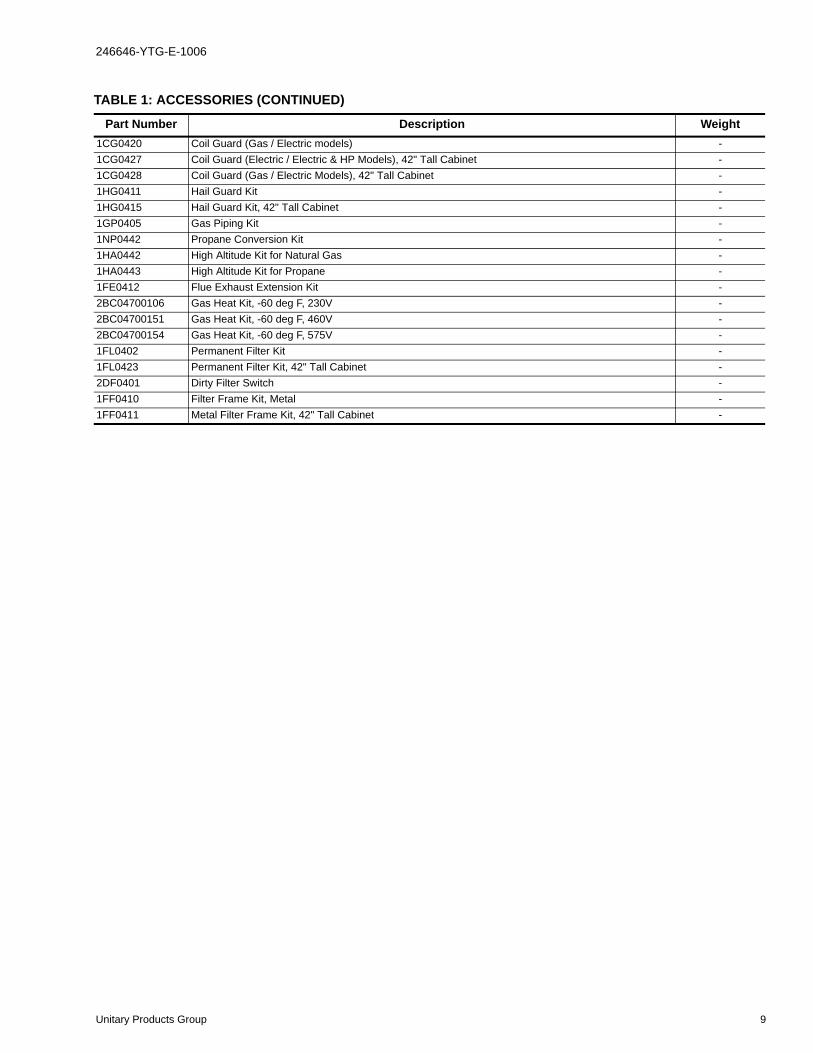
1CG0420 Coil Guard (Gas / Electric models) -1CG0427 Coil Guard (Electric / Electric & HP Models), 42" Tall Cabinet -1CG0428 Coil Guard (Gas / Electric Models), 42" Tall Cabinet -1HG0411 Hail Guard Kit -1HG0415 Hail Guard Kit, 42" Tall Cabinet -1GP0405 Gas Piping Kit -1NP0442 Propane Conversion Kit -1HA0442 High Altitude Kit for Natural Gas -1HA0443 High Altitude Kit for Propane -1FE0412 Flue Exhaust Extension Kit -2BC04700106 Gas Heat Kit, -60 deg F, 230V -2BC04700151 Gas Heat Kit, -60 deg F, 460V -2BC04700154 Gas Heat Kit, -60 deg F, 575V -1FL0402 Permanent Filter Kit -1FL0423 Permanent Filter Kit, 42" Tall Cabinet -2DF0401 Dirty Filter Switch -1FF0410 Filter Frame Kit, Metal -1FF0411 Metal Filter Frame Kit, 42" Tall Cabinet -
TABLE 1: ACCESSORIES (CONTINUED)
Part Number Description Weight
Unitary Products Group 9

246646-YTG-E-1006
NOMENCLATURE
D M 090 N10 A 2 A AA 3 0 1 2 4 A
D = A/C, Single Pkg., R-22
Product Category
A = Std. Motor
Airflow
B = Std. Motor/Econo./Barometric Relief (Downflow
Only)
C = Std. Motor/Econo./Power Exhaust (Downflow Only)D = Std. Motor/Motorized Damper (Downflow Only)
E = Std. Motor/Horizontal Economizer (No Baro.)
F = Std. Motor/Slab Econo./Power Exhaust
(Downflow Only)
G = Std. Motor/Slab Econo./Barometric Relief
(Downflow Only)
N = Hi Static Mtr.
P = Hi Static Mtr./Econo./Barometric Relief
(Downflow Only)
Q = Hi Static Mtr./Econo./Power Exhaust
(Downflow Only)
R = Hi Static Mtr./Motorized Damper (Downflow Only)
S = Hi Static Mtr./Horizontal Economizer (No Baro.)
T = Hi Static Mtr./Slab Econo./Power Exhaust
(Downflow Only)
U = Hi Static Mtr./Slab Econo./Barometric Relief
(Downflow only)
3 = Third Generation
Product Generation
4 = Fourth Generation
5 = Fifth Generation
6 = Sixth Generation
C00 = Cooling Only. No heat installed
Heat Type and Nominal Heat Capacity
N10 = 100 MBH Output Aluminized Steel
N15 = 150 MBH Output Aluminized Steel
N20 = 200 MBH Output Aluminized Steel
S10 = 100 MBH Output Stainless Steel
S15 = 150 MBH Output Stainless Steel
S20 = 200 MBH Output Stainless Steel
E09 = 9 KW
E18 = 18 KW
E24 = 24 KW
E36 = 36 KW
E54 = 54 KW
Gas Heat Options
Electric Heat Options
078 = 6.5 Ton
Nominal Cooling Capacity
090 = 7.5 Ton
102 = 8.5 Ton
120 = 10.0 Ton
150 = 12.5 Ton
Product Identifier
M = 9.0 EER A/C
H = 11.0+ EER A/C
Voltage
2 = 208/230-3-60
3 = 380-3-60
4 = 460-3-60
5 = 575-3-60
Product Style
A = Style A
B = Style B
C = Style C
A = No Options Installed
Installation Options
B = Option 1
C = Option 2
D = Options 1 & 2
E = Option 3
F = Option 4
G = Options 1 & 3
H = Options 1 & 4
J = Options 1, 2 & 3
K = Options 1, 2, & 4
L = Options 1,3 & 4
M = Options 1, 2, 3, & 4
N = Options 2 & 3
P = Options 2 & 4
Q = Options 2, 3, & 4
R = Options 3 & 4
S = Option 5
T = Options 1 & 5
U = Options 1, 3, & 5
V = Options 1, 4, & 5
W = Options 1, 3, 4, & 5
X = Options 3 & 5
Y = Options 4 & 5
Z = Options 3, 4 & 5
1 = Disconnect
2 = Non-Pwr'd Conv. Outlet
3 = Smoke Detector S.A.
4 = Smoke Detector R.A.
5 = Pwr'd Conv. Outlet
Options
SS Drain Pan
Configuration Options (not required for all units)
These four digits will not be assigned until a quote is requested, or an order placed.
CPC Controller, DFS, APS
Johnson Controller, DFS, APS
Honeywell Controller, DFS, APS
Novar Controller, DFS, APS
Simplicity IntelliComfort Controller
Simplicity IntelliComfort Controller w/ModLinc
2" Pleated filters
BAS Ready Unit with Belimo Economizer
Shipping Bag
Any Combination of Additional Options that Don’t Have an Option Code Pre-assigned
AA = None
AB = Phase Monitor
AC = Coil Guard
AD = Dirty Filter Switch
AE = Phase Monitor & Coil Guard
AF = Phase Monitor & Dirty Filter Switch
AG = Coil Guard & Dirty Filter Switch
AH = Phase Monitor, Coil Guard & Dirty Filter Switch
Additional Options
RC = Coil Guard, Shipping Bag & American Flag
TA = Technicoat Condenser Coil
TJ = Technicoat Evaporator Coil
TS = Technicoat Evaporator & Condenser Coils
6.5-12.5 Ton York® Model Number Nomenclature
ZZ = If desired option combination is not listed above, ZZ will be assigned and configuration options will be
located in digits 15-18.
10 Unitary Products Group

246646-YTG-E-1006
TABLE 2: DH PHYSICAL DATA
ComponentModels
078 090 102 120 150
EvaporatorBlower
Blower, Centrifugal (Dia. X Wd. in.) 12 x 12 12 x 12 12 X 12 15 x 15 15 x 15
Motor, Standard (HP) 1-1/2 2 3 2 3
Motor, Optional (HP) 2 3 3 3 5
EvaporatorCoil
Rows 3 3 3 4 4
Fins per Inch 15 15 15 15 15
Height (in.) 32 32 32 40 40
Face Area (ft.2 each) 10.67 10.67 10.67 13.2 13.2
CondenserFan
(2 per Unit)
Propeller Dia. (in., each) 24 24 24 24 24
Motor (HP, each) 1/3 1/3 1/3 3/4 3/4
CFM, Nominal (each) 3400 3400 3400 4400 4400
CondenserCoil
(2 per unit)
Rows (each)Sys 1: 2 Row
2 2 2 2Sys 2: 1 Row
Fins per Inch 20 20 20 20 20
Height (in., each) 36 36 36 44 44
Face Area (ft.2 each) 12 12 12 14.5 14.5
RefrigerantCharge
System 1 (lb./oz.) 8/0 8/12 9/8 12/0 9/14
System 2 (lb./oz.) 4/12 9/0 8/2 11/0 9/4
CompressorsQuantity 2 2 2 2 2
Type Recip. Recip Recip. Recip Scroll
Air FiltersSize (Wd. x Ht. x
Thickness in.) 25x16x2 25x16x2 25x16x2 25x20x2 25x20x2
Number Per Unit 4 4 4 4 4
Unitary Products Group 11

246646-YTG-E-1006
TABLE 3: DH CAPACITY RATINGS
Size(Tons) Model
Cooling CapacityARI Ratings1
CFMSound Rating(dB)2
NominalElectric
HeatCapacity3
(kW)
Gas Heat Capacity GasLineSize
(in. OD)MBH EER IPLV Input(MBH)
Output(MBH)
SeasonalEfficiency
(%)
Temp.Rise (°F)
078(6-1/2)
CoolingOnly
75 11.5 11.90 2421 84
- - - - - -
ElectricHeat
9, 18, 24,36 - - - - -
Gas Heat - 120 96 80 20-50 3/4
Gas Heat - 180 144 80 35-65 3/4
090(7-1/2)
CoolingOnly
89 11.5 12.0 3000 84
- - - - - -
ElectricHeat 18, 36 - - - - -
Gas Heat - 120 96 80 15-45 3/4
Gas Heat - 180 144 80 30-60 3/4
102(8-1/2)
CoolingOnly
99 11.0 11.50 2692 84
- - - - - -
ElectricHeat
9, 18, 24,36 - - - - -
Gas Heat - 120 96 80 15-45 3/4
Gas Heat - 180 144 80 30-60 3/4
120(10)
CoolingOnly
115 11.0 11.70 3840 90
- - - - - -
ElectricHeat
18, 24, 36,54 - - - - -
Gas Heat - 180 144 80 20-50 3/4
Gas Heat - 240 192 80 35-65 3/4
150(12-1/2)
CoolingOnly
146 10.0 10.70 4100 90
- - - - - -
ElectricHeat
18, 24, 36,54 - - - - -
Gas Heat - 180 144 80 10-40 3/4
Gas Heat - 240 192 80 25-55 3/4
1 Rated at 95°F ambient 80°F dry bulb and 67°F wet bulb.2 Rated in accordance with ARI 270 standard.3 See Table 20.
TABLE 4: UNIT VOLTAGE LIMITATIONSPOWER RATING MIN. MAX.
208/230-3-60 187 252
460-3-60 432 504
575-3-60 540 630
12 Unitary Products Group
246646-YTG-E-1006
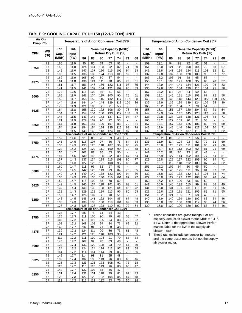
TABLE 9: COOLING CAPACITY DH150 (12-1/2 TON) UNITAir On
Evap. Coil Temperature of Air on Condenser Coil 85°F Temperature of Air on Condenser Coil 95°F
CFM WB(°F)
Tot.Cap.*(MBH)
Tot.Input†(kW)
Sensible Capacity (MBH)*Return Dry Bulb (°F)
Tot.Cap.*(MBH)
Tot.Input†(kW)
Sensible Capacity (MBH)*Return Dry Bulb (°F)
86 83 80 77 74 71 68 86 83 80 77 74 71 68
375072 165 11.9 95 85 74 63 52 - - 159 13.1 94 83 72 62 51 - -67 158 11.8 124 114 103 92 82 71 60 151 13.0 121 111 100 89 79 68 5762 148 11.6 147 137 126 115 105 94 83 141 12.8 141 135 124 113 103 92 8157 138 11.5 138 135 124 113 103 92 81 132 12.8 132 130 120 109 98 87 77
437572 169 11.9 105 92 80 67 54 - - 163 13.2 103 91 78 65 53 - -67 161 11.8 136 124 111 98 86 73 61 155 13.1 133 121 108 95 83 70 5762 151 11.7 151 146 136 123 111 98 85 144 12.9 144 141 134 121 109 96 8357 141 11.5 141 139 134 121 109 96 83 135 12.8 135 134 129 116 104 91 78
500072 172 12.0 115 100 86 71 56 - - 167 13.2 113 98 84 69 55 - -67 165 11.9 148 134 119 105 90 76 61 159 13.1 145 131 116 101 87 72 5862 155 11.7 155 155 146 132 117 102 88 148 12.9 148 148 144 129 115 100 8557 144 11.6 144 144 144 129 115 100 86 139 12.9 139 139 139 124 109 95 80
562572 172 11.9 121 105 88 71 55 - - 166 13.2 120 104 87 70 54 - -67 164 11.8 156 139 122 106 89 73 56 158 13.1 151 137 120 104 87 71 5462 154 11.7 154 154 150 133 117 100 83 147 12.9 147 147 145 128 112 95 7857 143 11.5 143 143 143 127 110 94 77 138 12.8 138 138 138 121 104 88 71
625072 171 11.9 127 109 90 72 53 - - 165 13.2 127 109 90 71 53 - -67 164 11.8 163 144 126 107 88 70 51 157 13.1 157 143 125 106 88 69 5062 154 11.6 154 154 154 135 116 98 79 146 12.9 146 146 146 127 108 90 7157 143 11.5 143 143 143 124 106 87 68 137 12.8 137 137 137 118 99 81 62
Temperature of Air on Condenser Coil 105°F Temperature of Air on Condenser Coil 115°F
375072 152 14.6 91 80 70 59 48 - - 145 16.2 88 78 67 56 46 - -67 143 14.5 118 107 97 86 75 64 54 135 15.9 114 104 93 82 72 61 5062 133 14.3 133 128 118 107 96 86 75 125 15.8 125 122 111 101 90 79 6857 124 14.2 124 122 111 100 90 79 68 116 15.7 116 113 103 92 81 71 60
437572 156 14.7 101 88 76 63 50 - - 149 16.2 99 86 73 61 48 - -67 147 14.5 130 118 105 92 80 67 54 138 15.9 127 114 102 89 77 64 5162 137 14.3 137 134 128 115 103 90 77 129 15.8 129 127 122 109 96 84 7157 127 14.3 127 126 121 108 95 83 70 119 15.7 119 118 112 100 87 75 62
500072 160 14.7 111 96 82 67 53 - - 153 16.2 109 94 80 65 50 - -67 150 14.5 142 128 113 99 84 70 55 142 15.9 140 125 111 96 81 67 5262 140 14.4 140 140 138 123 109 94 80 132 15.8 132 132 132 118 103 88 7457 130 14.3 130 130 130 116 101 87 72 122 15.8 122 122 122 108 93 78 64
562572 159 14.7 118 102 85 68 52 - - 152 16.2 116 100 83 66 50 - -67 149 14.5 145 134 118 101 85 68 51 141 15.9 140 132 115 99 82 66 4962 139 14.4 139 139 138 121 105 88 72 131 15.8 131 131 131 115 98 81 6557 129 14.3 129 129 129 113 96 80 63 121 15.8 121 121 121 105 88 71 55
625072 158 14.7 126 107 88 70 51 - - 151 16.2 124 105 87 68 49 - -67 148 14.5 148 141 122 104 85 67 48 140 15.9 140 139 120 102 83 64 4662 138 14.3 138 138 138 119 101 82 63 130 15.8 130 130 130 112 93 74 5657 128 14.3 128 128 128 110 91 72 54 120 15.8 120 120 120 102 83 64 46
Temperature of Air on Condenser Coil 125°F
375072 138 17.7 86 75 64 54 43 - -67 126 17.3 111 100 90 79 68 58 4762 118 17.2 118 116 105 94 83 73 6257 108 17.2 108 105 94 84 73 62 52
437572 142 17.7 96 84 71 58 46 - -67 130 17.3 124 111 99 86 73 61 4862 121 17.2 121 120 116 103 90 78 6557 111 17.2 111 109 104 91 79 66 54
500072 146 17.7 107 92 78 63 48 - -67 133 17.4 133 122 108 93 79 64 5062 124 17.2 124 124 124 112 97 83 6857 114 17.2 114 114 114 99 85 70 56
562572 145 17.7 114 98 81 65 48 - -67 132 17.4 132 130 113 96 80 63 4662 123 17.3 123 123 123 108 91 75 5857 113 17.2 113 113 113 96 80 63 47
625072 144 17.7 122 103 85 66 47 - -67 131 17.4 131 131 118 99 81 62 4362 122 17.3 122 122 122 104 85 67 4857 112 17.2 112 112 112 93 75 56 38
* These capacities are gross ratings. For net capacity, deduct air blower motor, MBH = 3.415 x kW. Refer to the appropriate Blower Perfor-mance Table for the kW of the supply air blower motor.
† These ratings include condenser fan motors and the compressor motors but not the supply air blower motor.
Unitary Products Group 17

246646-YTG-E-1006
NOTE: Electric heaters are rated at nominal voltage. Use this table to determine the electric heat capacity for heaters supplied at lower voltages.
NOTES FOR TABLES 21 THROUGH TABLE 30:• Blower performance includes dry coil and 2” throwaway
filters.
• Blower performance for gas heat includes the maximumnumber of heat tubes available for each tonnage.
ESP (External Static Pressure) given is that available for the supply and return air duct system. All internal resistances have been deducted from the total static pressure of the blower.
TABLE 18: ELECTRICAL DATA DH150 (12-1/2 TON) HIGH EFFICIENCY W/O PWRD CONVENIENCE OUTLET
RLA LRA FLA 3 5 3 5 3 5 3 5 3 5
ea. ea. ea. HP HP HP HP HP HP HP HP HP HP
None -- -- 60.4 65.6 65.9 71.1 70 80 80 90
2TP04521825 13.5 37.5 60.5 67.0 67.3 73.8 70 80 80 90
2TP04522425 18 50.0 76.1 82.6 83.0 89.5 80 90 90 90
2TP04523625 25.5 70.8 102.1 108.6 109.0 115.5 110 110 110 125
2TP04525425 40.6 112.7 154.5 161.0 161.4 167.9 175 175 175 175
None -- -- 60.4 65.6 65.9 71.1 70 80 80 90
2TP04521825 18 43.3 67.8 74.3 74.6 81.1 70 80 80 90
2TP04522425 24 57.7 85.8 92.3 92.7 99.2 90 100 100 100
2TP04523625 34 81.8 115.9 122.4 122.7 129.2 125 125 125 150
2TP04525425 129.9 143.5 150.0 150.4 156.9 175 175 175 175
None -- -- 29.9 32.7 32.1 34.9 35 40 40 40
2TP04521846 18 22.6 33.7 37.2 36.4 39.9 35 40 40 40
2TP04522446 24 30.1 42.7 46.2 45.5 49 45 50 50 50
2TP04523646 34 42.7 57.7 61.2 60.5 64 60 70 70 70
2TP04525446 54 67.8 71.6 75.1 74.3 77.8 80 90 80 90
None -- -- 23.8 25.7 25.6 27.5 30 30 30 35
2TP04521858 18 18.1 26.8 29.2 29 31.4 30 30 30 35
2TP04522458 24 24.1 34 36.4 36.2 38.6 35 40 40 40
2TP04523658 34 34.1 46 48.4 48.3 50.6 50 50 50 60
2TP04525458 54 54.2 57.1 59.5 59.3 61.7 70 70 70 70
*
Pwr
Exh
MotorElectric Heater
Model No.
Actual
KW
0.0
5.5 0.0
1.6 5.3 8.1 2.2 0.0
3.5 10.9 16.118.9 146.0
9.5 73.0
10.9 16.1 5.5 0.0
Maximum HACR breaker of the same AMP size is applicable.
7.6 58.4 1.3 4.1 6.0 1.8
MCA
w/Power
Exhaust
(Amps)
Max
Fuse*
Size
(Amps)
Max Fuse* Size
w/Power
Exhaust
(Amps)
FLA
Pwr
Conv
OutletHeater
Amps
Min. Circuit
Ampacity
(Amps)
FLA
208 18.9 146.0 3.5
230
460
575
Voltage
CompressorsOD Fan
Motors
Supply
Blower
Motor FLA
54
TABLE 19: ELECTRICAL DATA DH150 (12-1/2 TON) HIGH EFFICIENCY W/PWRD CONVENIENCE OUTLET
RLA LRA FLA 3 5 3 5 3 5 3 5 3 5
ea. ea. ea. HP HP HP HP HP HP HP HP HP HP
None -- -- 70.4 75.6 75.9 81.1 80 90 90 100
2TP04521825 13.5 37.5 73.0 79.5 79.8 86.3 80 90 90 100
2TP04522425 18 50.0 88.6 95.1 95.5 102.0 90 100 100 110
2TP04523625 25.5 70.8 114.6 121.1 121.5 128.0 125 125 125 150
2TP04525425 40.6 112.7 167.0 173.5 173.9 180.4 175 175 175 200
None -- -- 70.4 75.6 75.9 81.1 80 90 90 100
2TP04521825 18 43.3 80.3 86.8 87.1 93.6 90 90 90 100
2TP04522425 24 57.7 98.3 104.8 105.2 111.7 100 110 110 125
2TP04523625 34 81.8 128.4 134.9 135.2 141.7 150 150 150 150
2TP04525425 129.9 156.0 162.5 162.9 169.4 175 175 175 175
None -- -- 34.9 37.7 37.1 39.9 40 45 45 45
2TP04521846 18 22.6 39.9 43.4 42.7 46.2 40 45 45 50
2TP04522446 24 30.1 49 52.5 51.7 55.2 50 60 60 60
2TP04523646 34 42.7 64 67.5 66.7 70.2 70 70 70 80
2TP04525446 54 67.8 77.8 81.3 80.6 84.1 90 90 90 90
None -- -- 27.8 29.7 29.6 31.5 35 35 35 35
2TP04521858 18 18.1 31.8 34.2 34 36.4 35 35 35 40
2TP04522458 24 24.1 39 41.4 41.2 43.6 40 45 45 45
2TP04523658 34 34.1 51 53.4 53.3 55.6 60 60 60 60
2TP04525458 54 54.2 62.1 64.5 64.3 66.7 70 70 70 70
*
2.2 5.0
7.6 58.4 1.3 4.1 6.0 1.8 4.0
9.5
3.5 10.9 16.1 5.5 10.0
3.5 10.9 16.1 5.5 10.0
73.0 1.6 5.3 8.1460
Maximum HACR breaker of the same AMP size is applicable.
575
Min. Circuit
Ampacity
(Amps)
MCA
w/Power
Exhaust
(Amps)
Max
Fuse*
Size
(Amps)
Max Fuse* Size
w/Power
Exhaust
(Amps)
Heater
Amps
FLA
208
230
CompressorsOD Fan
Motors
18.9 146.0
18.9 146.0
VoltageElectric Heater
Model No.
Actual
KW
Supply
Blower
Motor FLA
Pwr
Exh
Motor
FLA
Pwr
Conv
Outlet
54
TABLE 20: ELECTRIC HEAT MULTIPLIERSVOLTAGE
kW Cap. MultiplierNOMINAL RATING
240208 0.75
230 0.92
480 460 0.92
600 575 0.92
22 Unitary Products Group

246646-YTG-E-1006
TAB
LE 2
5: D
H15
0 (1
2-1/
2 TO
N) S
IDE
SHO
T B
LOW
ER P
ERFO
RM
AN
CE
CFM
Exte
rnal
Sta
tic P
ress
ure
0.2
0.4
0.6
0.8
1.0
1.2
1.4
1.6
1.8
2.0
RP
MBH
PW
atts
RPM
BHP
Wat
tsR
PM
BHP
Wat
tsR
PMBH
PW
atts
RPM
BH
PW
atts
RP
MBH
PW
atts
RPM
BHP
Wat
tsR
PMB
HP
Wat
tsR
PMBH
PW
atts
RP
MBH
PW
atts
3700
----
----
----
----
----
----
----
----
----
874
1.93
1801
927
2.04
1906
984
2.27
2113
1037
2.41
2245
1089
2.57
2399
1138
2.68
2499
1178
2.82
2628
3800
----
----
----
----
----
----
840
1.82
1699
888
2.01
1871
941
2.14
1993
997
2.36
2202
1048
2.50
2334
1099
2.67
2485
1146
2.77
2586
1186
2.93
2728
3900
----
----
----
----
----
----
855
1.92
1786
903
2.09
1947
954
2.24
2085
1009
2.46
2295
1060
2.60
2427
1109
2.76
2576
1155
2.88
2680
1195
3.04
2834
4000
----
----
----
----
----
----
870
2.01
1877
917
2.18
2028
968
2.34
2182
1022
2.57
2392
1071
2.71
2524
1120
2.87
2672
1163
2.98
2780
1204
3.16
2947
4100
----
----
----
----
----
----
885
2.12
1973
932
2.27
2115
982
2.45
2283
1035
2.68
2494
1083
2.82
2626
1130
2.98
2774
1171
3.10
2887
1212
3.29
3066
4200
----
----
----
834
2.11
1970
900
2.22
2072
946
2.37
2207
996
2.56
2390
1048
2.79
2601
1094
2.93
2733
1140
3.09
2881
1179
3.22
3000
1221
3.42
3192
4300
----
----
----
851
2.19
2042
915
2.33
2175
961
2.47
2305
1009
2.68
2501
1061
2.91
2712
1106
3.05
2844
1150
3.21
2993
1188
3.35
3119
1230
3.57
3324
4400
----
----
----
868
2.28
2121
931
2.45
2283
975
2.58
2409
1023
2.81
2616
1074
3.03
2828
1117
3.18
2960
1160
3.34
3111
1196
3.48
3245
1239
3.71
3462
4500
822
2.13
1990
885
2.37
2208
946
2.57
2395
990
2.70
2518
1037
2.94
2736
1087
3.16
2948
1129
3.30
3080
1171
3.47
3234
1204
3.62
3377
1247
3.87
3607
4600
838
2.23
2083
901
2.47
2301
961
2.69
2511
1004
2.82
2633
1051
3.07
2862
1099
3.30
3072
1141
3.44
3204
1181
3.61
3362
1212
3.77
3515
1256
4.03
3758
4700
854
2.34
2184
918
2.58
2401
976
2.82
2631
1019
2.95
2753
1064
3.21
2991
1112
3.43
3201
1152
3.58
3333
1191
3.75
3496
1221
3.93
3659
1265
4.20
3916
4800
870
2.46
2291
935
2.69
2508
991
2.96
2755
1033
3.09
2879
1078
3.35
3126
1125
3.58
3335
1164
3.72
3467
1201
3.90
3635
1229
4.09
3810
1273
4.38
4080
4900
887
2.58
2406
952
2.81
2622
1007
3.09
2883
1048
3.23
3011
1092
3.50
3265
1138
3.73
3473
1175
3.87
3605
1211
4.05
3779
1237
4.26
3967
1282
4.56
4250
5000
903
2.71
2527
968
2.94
2744
1022
3.24
3016
1062
3.38
3148
1105
3.66
3409
1151
3.88
3616
1187
4.02
3748
1222
4.21
3929
1245
4.43
4131
1291
4.75
4427
5100
919
2.85
2656
985
3.08
2872
1037
3.38
3152
1077
3.53
3291
1119
3.82
3558
1164
4.04
3763
1198
4.18
3895
1232
4.38
4083
1254
4.61
4301
1300
4.95
4610
5200
936
2.99
2791
1002
3.23
3007
1052
3.53
3293
1091
3.69
3439
1133
3.98
3711
1177
4.20
3914
1210
4.34
4046
1242
4.55
4244
1262
4.80
4477
1308
5.15
4800
5300
952
3.15
2934
1018
3.38
3149
1067
3.69
3438
1106
3.85
3593
1147
4.15
3869
1189
4.37
4070
1221
4.51
4202
1252
4.73
4409
1270
5.00
4660
1317
5.36
4996
5400
968
3.31
3083
1035
3.54
3298
1083
3.85
3587
1120
4.03
3753
1160
4.33
4032
1202
4.54
4231
1233
4.68
4363
1262
4.91
4580
1278
5.20
4848
----
----
----
5500
984
3.48
3240
1052
3.71
3455
1098
4.01
3740
1135
4.20
3918
1174
4.51
4200
1215
4.72
4396
1244
4.86
4528
1273
5.10
4757
1286
5.41
5044
----
----
----
5600
1001
3.65
3403
1069
3.88
3618
1113
4.18
3897
1149
4.39
4089
1188
4.69
4372
1228
4.90
4566
1256
5.04
4698
1283
5.30
4938
----
----
----
----
----
----
5700
1017
3.83
3574
1085
4.06
3788
1128
4.35
4058
1164
4.58
4265
1201
4.88
4549
1241
5.08
4740
1267
5.23
4872
1293
5.50
5125
----
----
----
----
----
----
5800
1033
4.02
3751
1102
4.25
3965
1143
4.53
4224
1178
4.77
4447
1215
5.07
4731
1254
5.28
4918
1279
5.42
5050
----
----
----
----
----
----
----
----
----
5900
1050
4.22
3936
1119
4.45
4149
1159
4.71
4393
1193
4.97
4635
1229
5.27
4917
1267
5.47
5101
----
----
----
----
----
----
----
----
----
----
----
----
6000
1066
4.43
4127
1136
4.66
4341
1174
4.90
4567
1207
5.18
4828
1243
5.48
5108
----
----
----
----
----
----
----
----
----
----
----
----
----
----
----
6100
1082
4.64
4326
1152
4.87
4539
1189
5.09
4745
1222
5.39
5027
----
----
----
----
----
----
----
----
----
----
----
----
----
----
----
----
----
----
6200
1098
4.86
4531
1169
5.09
4744
1204
5.29
4927
1236
5.61
5231
----
----
----
----
----
----
----
----
----
----
----
----
----
----
----
----
----
----
Hig
h H
orse
pow
er O
ptio
n R
equi
red
Unitary Products Group 27
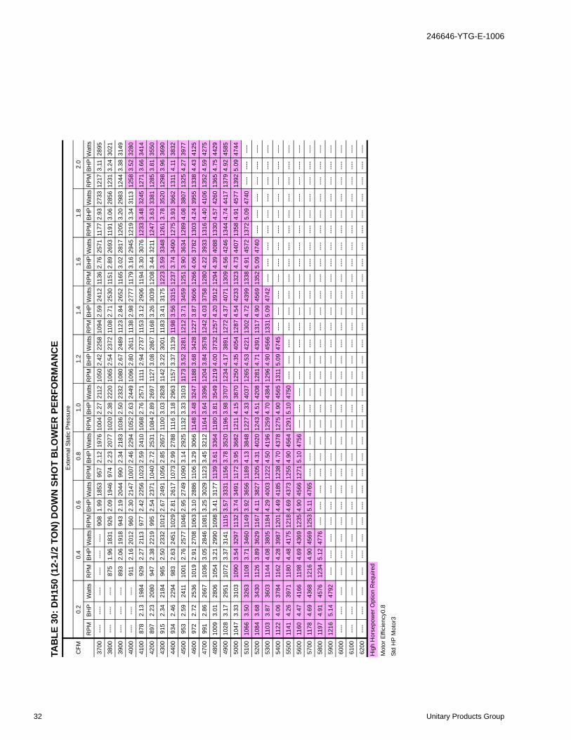
246646-YTG-E-1006
TAB
LE 3
0: D
H15
0 (1
2-1/
2 TO
N) D
OW
N S
HO
T B
LOW
ER P
ERFO
RM
AN
CE
CFM
Ext
erna
l Sta
tic P
ress
ure
0.2
0.4
0.6
0.8
1.0
1.2
1.4
1.6
1.8
2.0
RP
MB
HP
Wat
tsR
PM
BH
PW
atts
RP
MB
HP
Wat
tsR
PM
BH
PW
atts
RP
MB
HP
Wat
tsR
PM
BH
PW
atts
RP
MB
HP
Wat
tsR
PM
BH
PW
atts
RP
MB
HP
Wat
tsR
PM
BH
PW
atts
3700
----
----
----
----
----
----
908
1.99
1853
957
2.12
1976
1004
2.27
2112
1050
2.42
2258
1094
2.59
2412
1136
2.76
2571
1177
2.93
2733
1217
3.11
2895
3800
----
----
----
875
1.96
1831
926
2.09
1946
974
2.23
2077
1020
2.38
2220
1065
2.54
2372
1108
2.71
2530
1151
2.89
2693
1191
3.06
2856
1231
3.24
3021
3900
----
----
----
893
2.06
1918
943
2.19
2044
990
2.34
2183
1036
2.50
2332
1080
2.67
2489
1123
2.84
2652
1165
3.02
2817
1205
3.20
2983
1244
3.38
3149
4000
----
----
----
911
2.16
2012
960
2.30
2147
1007
2.46
2294
1052
2.63
2449
1096
2.80
2611
1138
2.98
2777
1179
3.16
2945
1219
3.34
3113
1258
3.52
3280
4100
878
2.13
1984
929
2.27
2113
977
2.42
2256
1023
2.59
2410
1068
2.76
2571
1111
2.94
2737
1153
3.12
2906
1194
3.30
3076
1233
3.48
3245
1271
3.66
3414
4200
897
2.23
2080
947
2.38
2219
995
2.54
2371
1040
2.72
2531
1084
2.89
2697
1127
3.08
2867
1168
3.26
3039
1208
3.44
3211
1247
3.63
3381
1285
3.81
3550
4300
915
2.34
2184
965
2.50
2332
1012
2.67
2491
1056
2.85
2657
1100
3.03
2828
1142
3.22
3001
1183
3.41
3175
1223
3.59
3348
1261
3.78
3520
1298
3.96
3690
4400
934
2.46
2294
983
2.63
2451
1029
2.81
2617
1073
2.99
2788
1116
3.18
2963
1157
3.37
3139
1198
3.56
3315
1237
3.74
3490
1275
3.93
3662
1311
4.11
3832
4500
953
2.59
2411
1001
2.76
2577
1046
2.95
2749
1090
3.14
2925
1132
3.33
3103
1173
3.52
3281
1212
3.71
3459
1251
3.90
3634
1289
4.08
3807
1325
4.27
3977
4600
972
2.72
2536
1019
2.91
2708
1063
3.10
2886
1106
3.29
3066
1148
3.48
3247
1188
3.68
3428
1227
3.87
3606
1266
4.06
3782
1303
4.24
3955
1338
4.43
4125
4700
991
2.86
2667
1036
3.05
2846
1081
3.25
3029
1123
3.45
3212
1164
3.64
3396
1204
3.84
3578
1242
4.03
3758
1280
4.22
3933
1316
4.40
4106
1352
4.59
4275
4800
1009
3.01
2806
1054
3.21
2990
1098
3.41
3177
1139
3.61
3364
1180
3.81
3549
1219
4.00
3732
1257
4.20
3912
1294
4.39
4088
1330
4.57
4260
1365
4.75
4429
4900
1028
3.17
2951
1072
3.37
3141
1115
3.57
3331
1156
3.78
3520
1196
3.98
3707
1234
4.17
3891
1272
4.37
4071
1309
4.56
4246
1344
4.74
4417
1379
4.92
4585
5000
1047
3.33
3103
1090
3.54
3297
1132
3.74
3491
1172
3.95
3682
1211
4.15
3870
1250
4.35
4054
1287
4.54
4233
1323
4.73
4407
1358
4.91
4577
1392
5.09
4744
5100
1066
3.50
3263
1108
3.71
3460
1149
3.92
3656
1189
4.13
3848
1227
4.33
4037
1265
4.53
4221
1302
4.72
4399
1338
4.91
4572
1372
5.09
4740
----
----
----
5200
1084
3.68
3430
1126
3.89
3629
1167
4.11
3827
1205
4.31
4020
1243
4.51
4208
1281
4.71
4391
1317
4.90
4569
1352
5.09
4740
----
----
----
----
----
----
5300
1103
3.87
3603
1144
4.08
3805
1184
4.29
4003
1222
4.50
4196
1259
4.70
4384
1296
4.90
4566
1331
5.09
4742
----
----
----
----
----
----
----
----
----
5400
1122
4.06
3784
1162
4.28
3987
1201
4.49
4185
1238
4.70
4378
1275
4.90
4565
1311
5.09
4745
----
----
----
----
----
----
----
----
----
----
----
----
5500
1141
4.26
3971
1180
4.48
4175
1218
4.69
4373
1255
4.90
4564
1291
5.10
4750
----
----
----
----
----
----
----
----
----
----
----
----
----
----
----
5600
1160
4.47
4166
1198
4.69
4369
1235
4.90
4566
1271
5.10
4756
----
----
----
----
----
----
----
----
----
----
----
----
----
----
----
----
----
----
5700
1178
4.69
4368
1216
4.90
4569
1253
5.11
4765
----
----
----
----
----
----
----
----
----
----
----
----
----
----
----
----
----
----
----
----
----
5800
1197
4.91
4576
1234
5.12
4776
----
----
----
----
----
----
----
----
----
----
----
----
----
----
----
----
----
----
----
----
----
----
----
----
5900
1216
5.14
4792
----
----
----
----
----
----
----
----
----
----
----
----
----
----
----
----
----
----
----
----
----
----
----
----
----
----
----
6000
----
----
----
----
----
----
----
----
----
----
----
----
----
----
----
----
----
----
----
----
----
----
----
----
----
----
----
----
----
----
6100
----
----
----
----
----
----
----
----
----
----
----
----
----
----
----
----
----
----
----
----
----
----
----
----
----
----
----
----
----
----
6200
----
----
----
----
----
----
----
----
----
----
----
----
----
----
----
----
----
----
----
----
----
----
----
----
----
----
----
----
----
----
Hig
h H
orse
pow
er O
ptio
n R
equi
red
Mot
or E
ffici
ency
0.8
Std
HP
Mot
or3
32 Unitary Products Group

246646-YTG-E-1006
TABLE 31: ADDITIONAL STATIC RESISTANCE DH120 AND 150
CFM Cooling Only1 Economizer2 3Electric Heat KW2
9 18 24 36 541900 0.06 0.02 0.05 0.06 0.07 0.08 0.102100 0.07 0.02 0.06 0.07 0.08 0.09 0.112300 0.08 0.02 0.07 0.08 0.09 0.10 0.132500 0.09 0.02 0.08 0.09 0.10 0.11 0.142700 0.11 0.03 0.09 0.10 0.12 0.13 0.162900 0.12 0.03 0.10 0.11 0.13 0.14 0.183100 0.14 0.03 0.12 0.13 0.15 0.16 0.203300 0.16 0.03 0.13 0.14 0.17 0.18 0.223500 0.18 0.04 0.15 0.16 0.19 0.20 0.243700 0.20 0.04 0.17 0.18 0.21 0.22 0.263900 0.23 0.04 0.19 0.20 0.23 0.24 0.284100 0.25 0.04 0.21 0.22 0.25 0.26 0.314300 0.28 0.05 0.23 0.24 0.28 0.29 0.344500 0.30 0.05 0.25 0.26 0.30 0.31 0.374700 0.33 0.05 0.28 0.29 0.33 0.34 0.404900 0.36 0.05 0.30 0.31 0.35 0.37 0.435100 0.39 0.06 0.33 0.34 0.38 0.40 0.465300 0.42 0.06 0.35 0.37 0.41 0.43 0.495500 0.45 0.06 0.38 0.40 0.44 0.46 0.535700 0.48 0.06 0.41 0.43 0.47 0.49 0.565900 0.52 0.07 0.44 0.46 0.50 0.53 0.596100 0.56 0.07 0.47 0.49 0.53 0.56 0.626300 0.60 0.07 0.50 0.53 0.56 0.59 0.65
1 Add these resistance values to the available static resistance in the respective Blower Performance Tables.2 Deduct these resistance values from the available external static pressure shown in the respective Blower Performance Table.3 The pressure drop through the economizer is greater for 100% outdoor air than for 100% return air. If the resistance of the return
air duct system is less than 0.25 IWG, the unit will deliver less CFM during full economizer operation.
TABLE 32: ADDITIONAL STATIC RESISTANCE DH078, 090, 102
CFM Cooling Only1 Economizer2 3Electric Heat KW2
9 18 24 36 541900 -0.004 0.07 0.05 0.06 0.07 0.08 0.102100 0.01 0.09 0.06 0.07 0.08 0.09 0.112300 0.01 0.11 0.07 0.08 0.09 0.10 0.132500 0.02 0.13 0.08 0.09 0.10 0.11 0.142700 0.03 0.16 0.09 0.10 0.12 0.13 0.162900 0.04 0.18 0.10 0.11 0.13 0.14 0.183100 0.05 0.20 0.12 0.13 0.15 0.16 0.203300 0.06 0.22 0.13 0.14 0.17 0.18 0.223500 0.07 0.24 0.15 0.16 0.19 0.20 0.243700 0.08 0.27 0.17 0.18 0.21 0.22 0.263900 0.09 0.29 0.19 0.20 0.23 0.24 0.284100 0.09 0.31 0.21 0.22 0.25 0.26 0.314300 0.10 0.33 0.23 0.24 0.28 0.29 0.34
1 Deduct these resistance values to the available static resistance in the respective Blower Performance Tables.2 Deduct these resistance values from the available external static pressure shown in the respective Blower Performance Table.3 The pressure drop through the economizer is greater for 100% outdoor air than for 100% return air. If the resistance of the return
air duct system is less than 0.25 IWG, the unit will deliver less CFM during full economizer operation.
Unitary Products Group 33
246646-YTG-E-1006
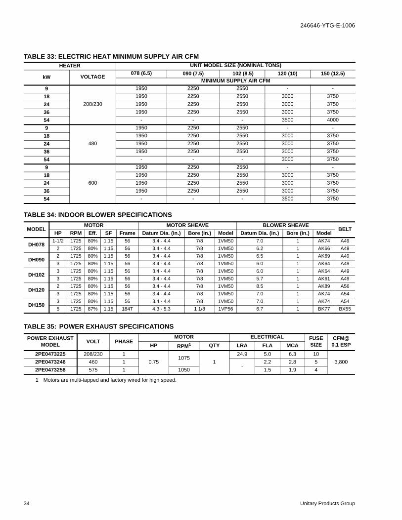
TABLE 33: ELECTRIC HEAT MINIMUM SUPPLY AIR CFMHEATER UNIT MODEL SIZE (NOMINAL TONS)
kW VOLTAGE 078 (6.5) 090 (7.5) 102 (8.5) 120 (10) 150 (12.5)MINIMUM SUPPLY AIR CFM
9
208/230
1950 2250 2550 - -18 1950 2250 2550 3000 375024 1950 2250 2550 3000 375036 1950 2250 2550 3000 375054 - - - 3500 40009
480
1950 2250 2550 - -18 1950 2250 2550 3000 375024 1950 2250 2550 3000 375036 1950 2250 2550 3000 375054 - - - 3000 37509
600
1950 2250 2550 - -18 1950 2250 2550 3000 375024 1950 2250 2550 3000 375036 1950 2250 2550 3000 375054 - - - 3500 3750
TABLE 34: INDOOR BLOWER SPECIFICATIONS
MODELMOTOR MOTOR SHEAVE BLOWER SHEAVE
BELTHP RPM Eff. SF Frame Datum Dia. (in.) Bore (in.) Model Datum Dia. (in.) Bore (in.) Model
DH0781-1/2 1725 80% 1.15 56 3.4 - 4.4 7/8 1VM50 7.0 1 AK74 A49
2 1725 80% 1.15 56 3.4 - 4.4 7/8 1VM50 6.2 1 AK66 A49
DH0902 1725 80% 1.15 56 3.4 - 4.4 7/8 1VM50 6.5 1 AK69 A493 1725 80% 1.15 56 3.4 - 4.4 7/8 1VM50 6.0 1 AK64 A49
DH1023 1725 80% 1.15 56 3.4 - 4.4 7/8 1VM50 6.0 1 AK64 A493 1725 80% 1.15 56 3.4 - 4.4 7/8 1VM50 5.7 1 AK61 A49
DH1202 1725 80% 1.15 56 3.4 - 4.4 7/8 1VM50 8.5 1 AK89 A563 1725 80% 1.15 56 3.4 - 4.4 7/8 1VM50 7.0 1 AK74 A54
DH1503 1725 80% 1.15 56 3.4 - 4.4 7/8 1VM50 7.0 1 AK74 A545 1725 87% 1.15 184T 4.3 - 5.3 1 1/8 1VP56 6.7 1 BK77 BX55
TABLE 35: POWER EXHAUST SPECIFICATIONSPOWER EXHAUST
MODEL VOLT PHASEMOTOR ELECTRICAL FUSE
SIZECFM@ 0.1 ESPHP RPM1 QTY LRA FLA MCA
2PE0473225 208/230 10.75
10751
24.9 5.0 6.3 103,8002PE0473246 460 1
-2.2 2.8 5
2PE0473258 575 1 1050 1.5 1.9 4
1 Motors are multi-tapped and factory wired for high speed.
34 Unitary Products Group

246646-YTG-E-1006
FIGURE 3 - UNIT CENTER OF GRAVITY
FIGURE 2 - UNIT 4 POINT LOAD
TABLE 36: 4 POINT LOAD WEIGHT
ModelLocation (lbs.)
A B C DDH078 197 147 230 309DH090 199 148 232 311DH102 201 150 234 315DH120 265 226 330 386DH150 263 224 327 383
Unit Model Number X Y
DH078 38 23
DH090 38 23
DH102 38 23
DH120 47 1/2 25 1/2
DH150 47 1/2 25 1/2
D
A
CBLEFT
FRONT
XY
LEFTFRONT
FIGURE 4 - UNIT 6 POINT LOAD
TABLE 37: 6 POINT LOAD WEIGHT
ModelLocations (lbs.)
A B C D E FDH078 138 113 93 146 176 216DH090 139 113 94 147 178 218DH102 141 115 95 149 180 221DH120 181 163 147 214 237 264DH150 180 161 146 213 235 262
TABLE 38: UNIT WEIGHT
Model Shipping Weight (lbs.)
Operating Weight (lbs.)
DH078 888 883DH090 895 890DH102 905 900DH120 1212 1207DH150 1202 1197
W/ECON. 85 84W/PE 150 148
W/ELECT. HEAT1
1 54 KW Heater
49 49
W/GAS HEAT2
2 8 Tube Heat Exchanger
110 110
D
A
C
B
E
F
LEFT
FRONT
Unitary Products Group 35

246646-YTG-E-1006
FIGURE 5 - UNIT DIMENSIONS
See DetailA
For BaserailDimensionsSee Detail B
8927
59
4-1/4
6-3/16
17-3/16
24-3/16
30-3/16
ConveniencePower OutletEntryØ 7/8
PowerEntry
Ø 2-1/2
30-11/32
ControlEntryØ 7/8
PowerEntry
Ø 2-1/2
LEFT
FRONTFor DrainDimensionsSee Detail C
11-1/2
X
TABLE 39: UNIT HEIGHTUnit Model Number X
DH078 42DH090 42DH102 42DH120 50 3/4DH150 50 3/4
TABLE 40: UNIT CLEARANCESTop1
1 Units must be installed outdoors. Overhanging structure or shrubs should not obstruct condenser air discharge outlet.
72” Right 12”
Front 36” Left 36”
Rear2
2 To remove the slide-out drain pan, a rear clearance of 60” is required. If space is unavailable, the drain pan can be removed through the front by separating the corner wall.
36” Bottom3
3 Units may be installed on combustible floors made from wood or class A, B or C roof covering materials.
0”
� � � � �� �
� � �� � � � � � �
� � � � � � � � � � � � � � � � � � � � � � � � � �
� � � � � � � � � � DETAIL A
� � � � �
� � ! � � �
" � � � #DETAIL B
� � � � #
DETAIL C
36 Unitary Products Group

246646-YTG-E-1006
FIGURE 6 - PREDATOR® ROOF CURB DIMENSIONS
# � � � � � �
� $ � � � "
� $
" $
" $
# $ � � � #
�
" � % & � '
� ( ) * + � % , - � - , � . � * ( - , /
� 0 1 � / , ) ) 0 / � ) , � % � 0 (
� ( ) * + � % , - � - , � . � * ( - , /
� 0 ( - , ( ) , / � ) , � % � 0 (
2 / 0 ( %
/ � � 3 %
) * � � + &
/ , % * / (
FIGURE 7 - SUNLINE™ TO PREDATOR® TRANSITION ROOF CURBS
� � � � #
! �
� $ � � � "� $ � � � "
� � � � � �
� ! � � � �
� $
" � �
" � # $ � � � #
" � % & �
2 / 0 ( % / � � 3 %
) * � � + &
/ , % * / (
Unitary Products Group 37
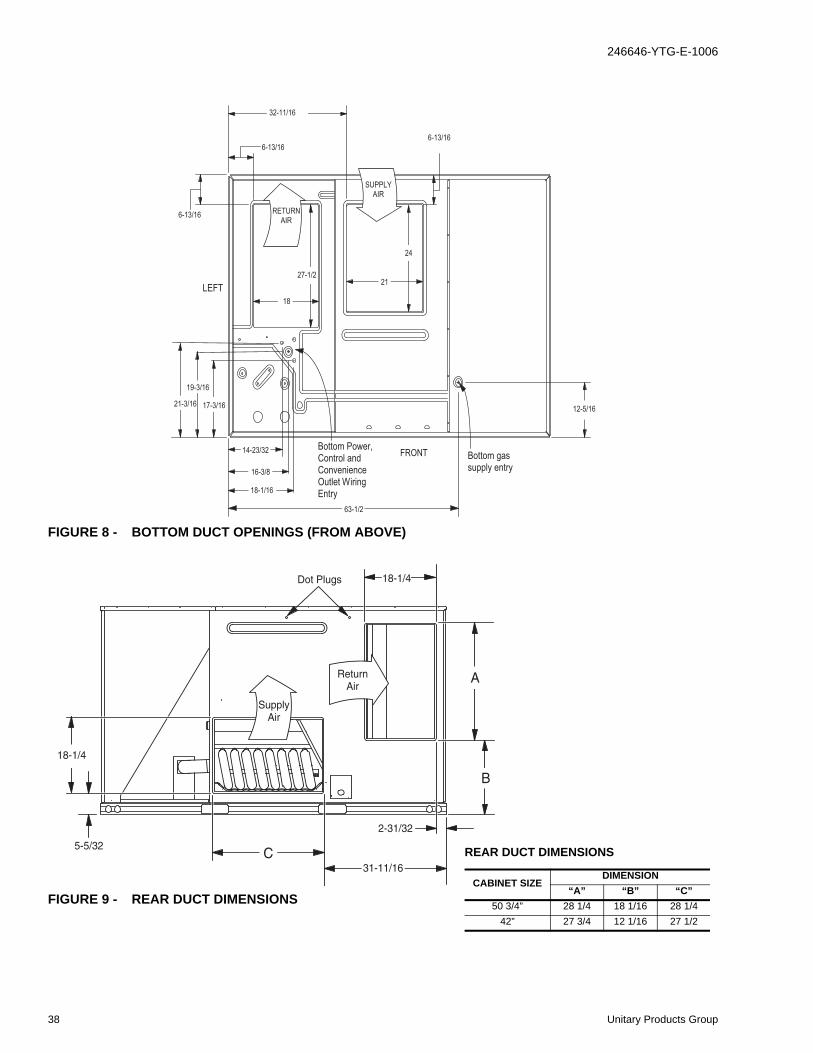
246646-YTG-E-1006
FIGURE 8 - BOTTOM DUCT OPENINGS (FROM ABOVE)
32-11/16
6-13/16
6-13/16
27-1/2
18
21-3/16
19-3/16
17-3/16
14-23/32
16-3/8
18-1/16
63-1/2
12-5/16
6-13/16
24
21LEFT
Bottom gassupply entry
Bottom Power,Control andConvenienceOutlet WiringEntry
SUPPLYAIR
RETURNAIR
FRONT
FIGURE 9 - REAR DUCT DIMENSIONS
Dot Plugs
18-1/4
5-5/32
31-11/16
2-31/32
18-1/4
ReturnAir
SupplyAir
A
B
C REAR DUCT DIMENSIONS
CABINET SIZEDIMENSION
“A” “B” “C”50 3/4” 28 1/4 18 1/16 28 1/4
42” 27 3/4 12 1/16 27 1/2
38 Unitary Products Group

246646-YTG-E-1006
FIGURE 10 -DOWNFLOW ECONOMIZER HOOD DETAIL
TABLE 41: ECONOMIZER USAGEApplication Cabinet Height Description Model
Bottom Return All Downflow economizer with barometric relief 2EE04705424
Side Return All Horizontal economizer without barometric relief 2EE047055241
1 Barometric relief must be ordered seperately and installed in duct work.
ERV or End Return42" Slab Economizer, 42” tall cabinet 2EE047056242
2 Barometric relief or fresh air hood not included. Must be ordered seperately.
50" Slab Economizer, 50” tall cabinet 2EE047052242
35 3/4
Outside Air
Intake Hood
26 25 3/430 1/426
39 1/2
or
47 1/2
Relief Hood for
Power Exhaust or
Barometric Relief
88 1/458 1/4
Unitary Products Group 39
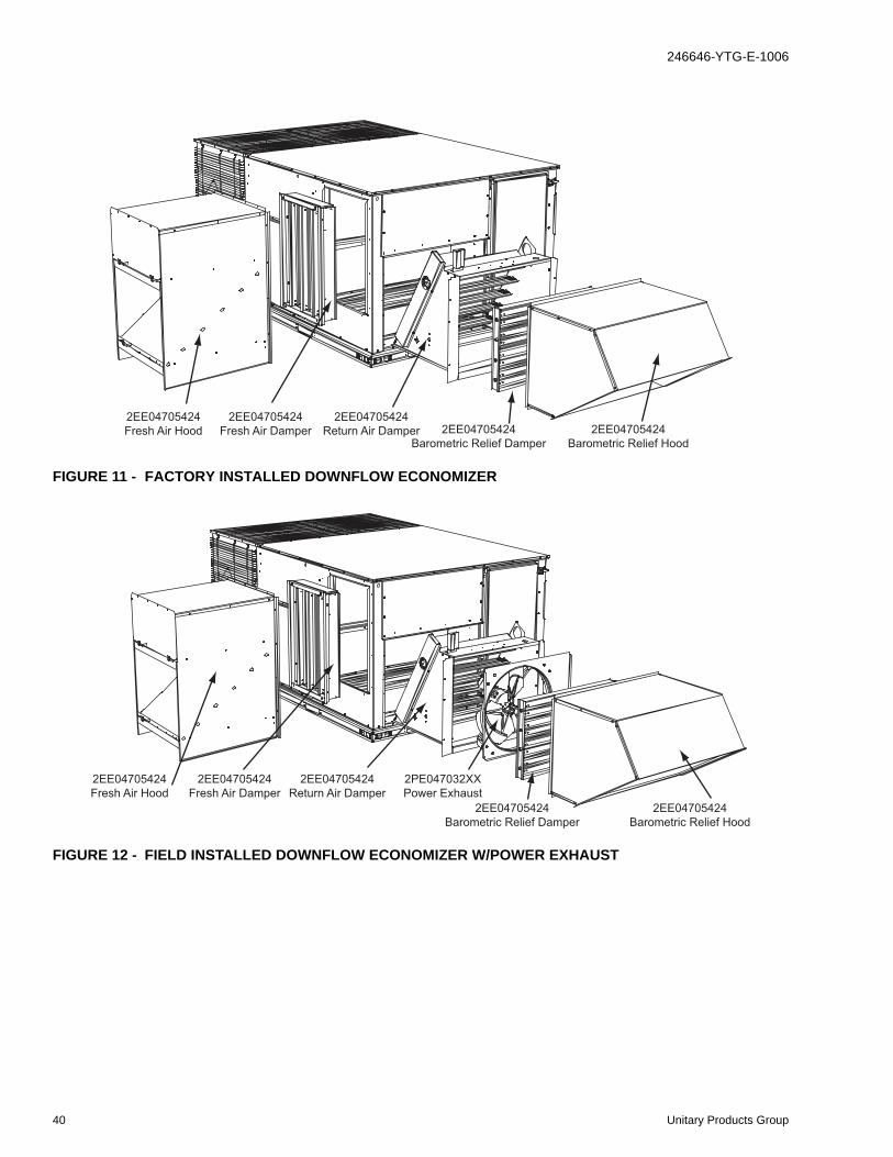
246646-YTG-E-1006
FIGURE 11 - FACTORY INSTALLED DOWNFLOW ECONOMIZER
FIGURE 12 - FIELD INSTALLED DOWNFLOW ECONOMIZER W/POWER EXHAUST
2EE04705424
Fresh Air Hood
2EE04705424
Fresh Air Damper
2EE04705424
Return Air Damper 2EE04705424
Barometric Relief Damper
2EE04705424
Barometric Relief Hood
2EE04705424
Fresh Air Hood
2EE04705424
Fresh Air Damper
2EE04705424
Return Air Damper
2PE047032XX
Power Exhaust
2EE04705424
Barometric Relief Damper
2EE04705424
Barometric Relief Hood
40 Unitary Products Group
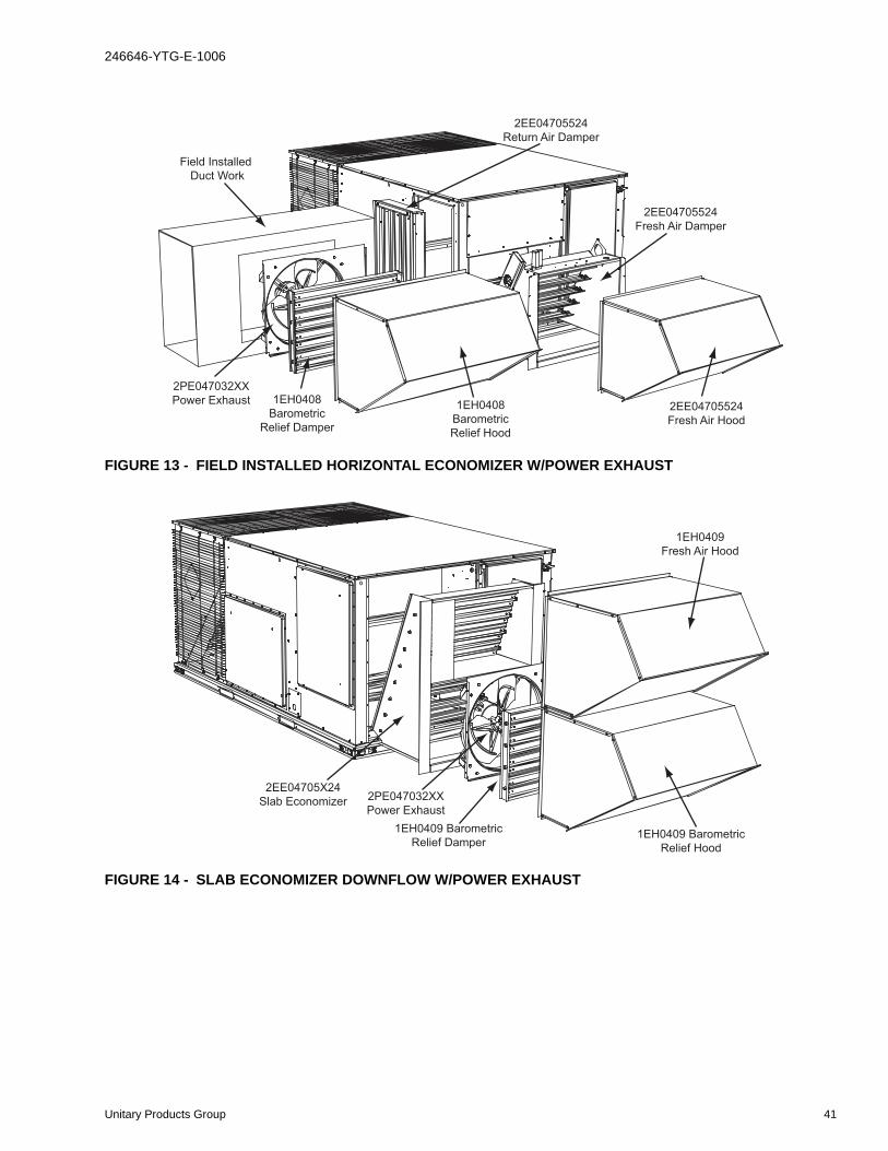
246646-YTG-E-1006
FIGURE 13 - FIELD INSTALLED HORIZONTAL ECONOMIZER W/POWER EXHAUST
FIGURE 14 - SLAB ECONOMIZER DOWNFLOW W/POWER EXHAUST
1EH0408
Barometric
Relief Hood
1EH0408
Barometric
Relief Damper
2PE047032XX
Power Exhaust2EE04705524
Fresh Air Hood
2EE04705524
Fresh Air Damper
2EE04705524
Return Air Damper
Field Installed
Duct Work
2EE04705X24
Slab Economizer 2PE047032XX
Power Exhaust
1EH0409 Barometric
Relief Damper1EH0409 Barometric
Relief Hood
1EH0409
Fresh Air Hood
Unitary Products Group 41

246646-YTG-E-1006
FIGURE 15 - SLAB ECONOMIZER END RETURN W/POWER EXHAUST
2EE04705X24
Slab Economizer
1EH0409
Barometric Relief Hood
1EH0409
Barometric Relief Damper
1EH0409
Fresh Air Hood
2PE047032XX
Power Exhaust
Field Installed
Duct Work
42 Unitary Products Group
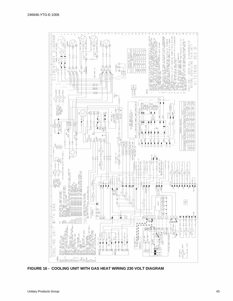
246646-YTG-E-1006
FIGURE 16 - COOLING UNIT WITH GAS HEAT WIRING 230 VOLT DIAGRAM
Unitary Products Group 43
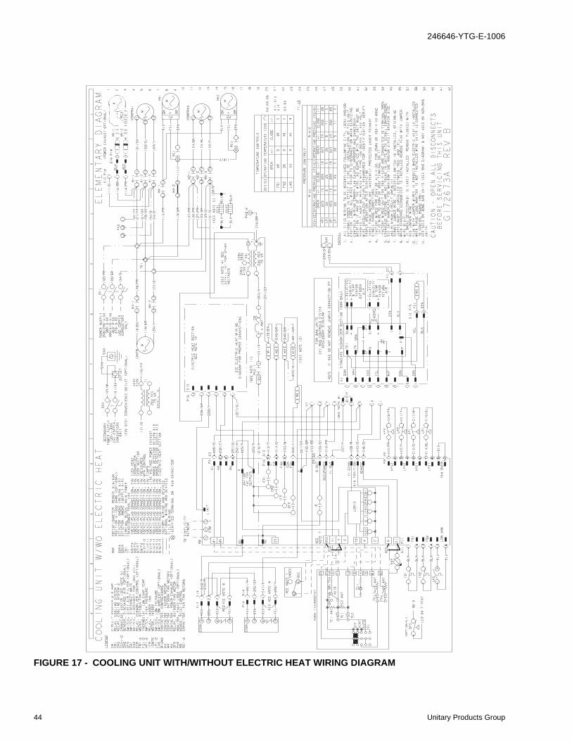
246646-YTG-E-1006
FIGURE 17 - COOLING UNIT WITH/WITHOUT ELECTRIC HEAT WIRING DIAGRAM
44 Unitary Products Group

246646-YTG-E-1006
FIGURE 18 - COOLING UNIT WITH GAS HEAT WIRING 460, 575 VOLT 50 HZ DIAGRAM
Unitary Products Group 45
246646-YTG-E-1006
GUIDE SPECIFICATIONSPREDATOR®
DH 078, 090, 102, 120 & 150, 11.5 EER
GENERAL
Units shall be manufactured by York International Unitary Products Group in an ISO 9001 certified facility. YORK® Predator® units are convertible single packages with a com-mon footprint cabinet and common roof curb for all 6-1/2 through 12-1/2 ton models. All units have two compressors with independent refrigeration circuits to provide 2 stages of cooling. The units were designed for light commercial appli-cations and can be easily installed on a roof curb, slab, or frame. All Predator® units are self-contained and assembled on rigid full perimeter base rails allowing for 3-way forklift access and overhead rigging. Every unit is completely charged, wired, piped, and tested at the factory to provide a quick and easy field installation. All units are convertible between side and down airflow. Independent economizer designs are used on side and down discharge applications, as well as all tonnage sizes. Predator® units are available in the following configurations: cooling only, cooling with electric heat, and cooling with gas heat. Electric heaters are available as factory-installed options or field-installed accessories.
DESCRIPTION
Units shall be factory assembled, single package, (Elec/Elec, Gas/Elec), designed for outdoor installation. Units shall have a minimum EER of 9.0. They shall have built in field convert-ible duct connections for down discharge supply/return or horizontal discharge supply/return and be available with fac-tory installed options or field installed accessories. The units shall be factory wired, piped and charged with R-22 refriger-ant and factory tested prior to shipment. All unit wiring shall be both numbered and color coded. The cooling performance shall be rated in accordance with DOE and ARI test proce-dures. Units shall be CSA certified to ANSI Z21.47 and UL 1995/CAN/CSA No. 236-M90 standards.
UNIT CABINET
Unit cabinet shall be constructed of G90 galvanized steel with exterior surfaces coated with a non-chalking, powder paint finish, certified at 1000 hour salt spray test per ASTM-B117 standards. Indoor blower sections shall be insulated with up to 1” thick insulation coated on the airside. Aluminum foil faced insulation shall be used in the unit’s compartments and be fastened to prevent insulation from entering the air stream. Cabinet doors shall be hinged with toolless access for easy servicing and maintenance. Full perimeter base rails shall be provided to assure reliable transit of equipment, overhead rigging, fork truck access and proper sealing on roof curb applications. Disposable 2” filters shall be furnished and be accessible through hinged access door. Fan perfor-mance measuring ports shall be provided on the outside of the cabinet to allow accurate air measurements of evaporator fan performance without removing panels or creating bypass
of the coils. Condensate pan shall be slide out design, con-structed of a non corrosive material, internally sloped and conforming to ASHRAE 62-B9 standards. Condensate con-nection shall be a minimum of ¾” I.D. female and be rigid mount connection.
INDOOR (EVAPORATOR) FAN ASSEMBLY
Fan shall be a belt drive assembly and include an adjustable pitch motor pulley. Job site selected brake horsepower shall not exceed the motors nameplate horsepower rating plus the service factor. Units shall be designed to operate within the service factor. Fan wheel shall be double inlet type with for-ward curve blades, dynamically balanced to operate smoothly throughout the entire range of operation. Airflow design shall be constant volume. Bearings shall be sealed and permanently lubricated for longer life and no mainte-nance. Entire blower assembly and motor shall be slide out design.
OUTDOOR (CONDENSER) FAN ASSEMBLY
The outdoor fans shall be of the direct drive type, discharge air vertically, have aluminum blades riveted to corrosion resistant steel spider brackets and shall be dynamically bal-anced for smooth operation. The outdoor fan motors shall have permanently lubricated bearings internally protected against overload conditions and staged independently. A cleaning window shall be provided on two sides of the units for coil cleaning.
REFRIGERANT COMPONENTS
Compressors:
A. Shall be fully hermetic type, direct drive, internally pro-tected with internal high-pressure relief and over temper-ature protection. The hermetic motor shall be suction gas cooled and have a voltage range of + or – 10% of the unit nameplate voltage.
B. Shall have internal spring isolation and sound muffling to minimize vibration and noise, and be externally isolated on a dedicated, independent mounting.
Coils:
A. Evaporator and condenser coils shall have aluminum plate fins mechanically bonded to seamless internally enhanced copper tubes with all joints brazed. Special Phenolic coating shall be available as a factory option.
B. Evaporator and condenser coils shall be of the direct expansion, draw-thru design.
46 Unitary Products Group
246646-YTG-E-1006
Refrigerant Circuit and Refrigerant Safety Components shall include:
A. Independent fixed-orifice or thermally operated expan-sion devices.
B. Solid core filter drier/strainer to eliminate any moisture or foreign matter.
C. Accessible service gage connections on both suction and discharge lines to charge, evacuate, and measure refrigerant pressure during any necessary servicing or troubleshooting, without losing charge.
D. The unit shall have two independent refrigerant circuits, equally split in 50% capacity increments.
Unit Controls:
A. Unit shall be complete with self-contained low-voltage control circuit protected by a resettable circuit breaker on the 24-volt transformer side.
B. Unit shall incorporate a lockout circuit which provides reset capability at the space thermostat or base unit should any of the following standard safety devices trip and shut off compressor:
C. Loss-of-charge/Low-pressure switch.
(1) High-pressure switch.
(2) Freeze-protection thermostat, evaporator coil. If any of the above safety devices trip, an LED (light-emitting diode) indicator shall flash a diagnostic code that indi-cates which safety switch has tripped.
D. Unit shall incorporate “AUTO RESET” compressor over temperature, over current protection.
E. Unit shall operate with conventional thermostat designs and have a low voltage terminal strip for easy hook-up.
F. Unit control board shall have on-board diagnostics and fault code display.
G. Standard controls shall include anti-short cycle and low voltage protection, and permit cooling operation down to 0 ºF.
H. Control board shall monitor each refrigerant safety switch independently.
I. Control board shall retain last 5 fault codes in non-vola-tile memory, which will not be lost in the event of a power loss.
GAS HEATING SECTION (IF EQUIPPED)
Heat exchanger and exhaust system shall be constructed of aluminized steel and shall be designed with induced draft combustion with post purge logic, energy saving direct spark ignition, and redundant main gas valve. The heat exchanger shall be of the tubular type, constructed of T1-40 aluminized steel for corrosion resistance and allowing minimum mixed air entering temperature of 40 ºF. Burners shall be of the in-
shot type, constructed of aluminum-coated steel. All gas pip-ing shall enter the unit cabinet at a single location, through either the side or bottom, without any field modifications. An integrated control board shall provide timed control of evapo-rator fan functioning and burner ignition. Heating section shall be provided with the following minimum protection:
A. Primary and auxiliary high-temperature limit switches.
B. Induced draft pressure sensor.
C. Flame roll out switch (manual reset).
D. Flame proving controls. Unit shall have two independent stages of capacity (60% 1st stage, 100% 2nd stage).
ELECTRIC HEATING SECTION (IF EQUIPPED) An electric heating section, with nickel chromium elements, shall be provided in a range of 9 thru 54 KW, offering two states of capacity all sizes. The heating section shall have a primary limit control(s) (automatic reset) to prevent the heat-ing element system from operating at an excessive tempera-ture. The Heating Section assembly shall slide out of the unit for easy maintenance and service. Units with Electric Heating Sections shall be wired for a single point power supply with branch circuit fusing (where required).
UNIT OPERATING CHARACTERISTICS
Unit shall be capable of starting and running at 125 ºF out-door temperature, exceeding maximum load criteria of ARI Standard 340/360. The compressor, with standard controls, shall be capable of operation down to 0 ºF outdoor tempera-ture. Unit shall be provided with fan time delay to prevent cold air delivery before heat exchanger warms up. (Gas heat only)
ELECTRICAL REQUIREMENTS - All unit power wiring shall enter unit cabinet at a single factory provided location and be capable of side or bottom entry to minimize roof penetrations and avoid unit field modifications. Separate side and bottom openings shall be provided for the control wiring.
STANDARD LIMITED WARRANTIES - Compressor – 5 Years, Heat Exchanger – 10 Years, Elect. Heat Elem. – 5 Years, Parts – 1 Year
FACTORY INSTALLED OPTIONAL OUTDOOR AIR (Shall be made available by either/or):
1. ELECTRONIC ENTHALPY AUTOMATIC ECONO-MIZER – Outdoor and return air dampers that are inter-locked and positioned by a fully-modulating, spring-return damper actuator. The maximum leakage rate for the outdoor air intake dampers shall not exceed 2% when dampers are fully closed and operating against a pressure differential of 0.5 IWG. A unit-mounted potenti-ometer shall be provided to adjust the outdoor and return air damper assembly to take in outdoor air to meet the minimum ventilation requirement of the conditioned space during normal operation. During economizer oper-ation, a mixed-air temperature control shall modulate the
Unitary Products Group 47

outdoor and return air damper assembly to prevent the supply air temperature from dropping below 55 ºF. Changeover from compressor to economizer operation shall be provided by an integral electronic enthalpy con-trol that feeds input into the basic module. The outdoor intake opening shall be covered with a rain hood that matches the exterior of the unit. Water eliminator/filters shall be provided. Simultaneous economizer/compressor operation is also possible. Dampers shall fully close on power loss. Available with barometric relief or power exhaust.
2. MOTORIZED OUTDOOR AIR DAMPERS – Outdoor and return air dampers that are interlocked and posi-tioned by a 2-position, spring-return damper actuator. The maximum leakage rate for the outdoor air intake dampers shall not exceed 2% when dampers are fully closed and operating against a pressure differential of 0.5 IWG. A unit-mounted potentiometer shall be provided to adjust the outdoor and return air damper assembly to take in the design CFM of outdoor air to meet the ventila-tion requirements of the conditioned space during normal operation. Whenever the indoor fan motor is energized, the dampers open up to one of two pre-selected posi-tions – regardless of the outdoor air enthalpy. Dampers return to the fully closed position when the indoor fan motor is de-energized. Dampers shall fully close on power loss.
ADDITIONAL FACTORY INSTALLED OPTIONS
• ALTERNATE INDOOR BLOWER MOTOR – For appli-cations with high restrictions, units are available withoptional indoor blower motors that provide higher staticoutput and/or higher airflow.
• CONVENIENCE OUTLET (POWERED/NON-POWERED)–Unit can be provided with an optional 120VAC GFCI outletwith cover on the corner of the unit housing the compressors.
• ELECTRIC HEAT - Electric Heaters range from 9 kW to54 kW and are available in all the voltage options of thebase unit.
• PHASE MONITOR - Designed to prevent damage in out-of-phase condition.
• COIL GUARD - Designed to prevent condenser coildamage.
• BAS CONTROLS - Include supply air sensor, return airsensor, dirty filter indicator and air proving switch.
• DIRTY FILTER SWITCH – This kit includes a differentialpressure switch that energizes the fault light on the unitthermostat, indicating that there is an abnormally high-pressure drop across the filters.
• BREAKER – An HACR breaker can be factory installedon gas heat units or cooling units with electric heat.
• DISCONNECT SWITCH - A disconnect can be factoryinstalled on a cooling only units sized for the largest elec-tric heat available.
• STAINLESS STEEL HEAT EXCHANGER – For applica-tions in a corrosive environment, this option provides afull stainless steel heat exchanger assembly.
• SMOKE DETECTOR – A smoke detector can be factorymounted and wired in the supply and/or return air com-partments.
OTHER PRE-ENGINEERED ACCESSORIES AVAILABLE
• ROOF CURB - 14” and 8” high, full perimeter knockdowncurb, with hinged design for quick assembly.
• BAROMETRIC RELIEF DAMPER – (Unit mounted –Downflow, Duct Mounted – Horizontal) – Contains a rainhood, air inlet screen, exhaust damper and mountinghardware. Used to relieve internal air pressure throughthe unit during economizer operation.
• PROPANE CONVERSION KIT – Contains new orificesand gas valve springs to convert from natural to L.P. gas.
• 60ºF GAS HEAT KIT – Provides an electric heat kit forthe gas compartment for use in extreme low ambientconditions.
• ECONOMIZER (Downflow and Horizontal flow)
• POWER EXHAUST – (Unit mount – Downflow, Ductmount – Horizontal flow)
• DUAL ENTHALPY KIT - Provides a second input toeconomizer to monitor return air.
Subject to change without notice. Printed in U.S.A. 246646-YTG-E-1006Copyright © 2006 by Unitary Products. All rights reserved. Supersedes: 246646-YTG-D-0806
Unitary 5005 NormanProducts York OKGroup Drive 73069