Embed Size (px)
Citation preview
DrillingBoring
Reaming BurnishingThreading
Specials
www.alliedmachine.com
Technical Guide Product Nomenclature

www.alliedmachine.com
North America Europe AsiaAllied Machine Allied Machine Allied Machine Europe Wohlhaupter® India
120 Deeds DriveDover, OH 44622
United States
485 West 3rd StreetDover, OH 44622
United States
93 Vantage PointPensnett EstateKingswinford
West MidlandsDY6 7FR, United Kingdom
B-23, 2nd FloorB Block Community Centre
Janakpuri, New Delhi - 110058India
ThreadMills USA™ Superion™ Wohlhaupter® GmbH4185 Crosstowne Ct #B
Evans, GA 30809United States
1285 S Patton St.Xenia, OH 45385
United States
Maybachstrasse 4Postfach 1264
72636 FrickenhausenGermany
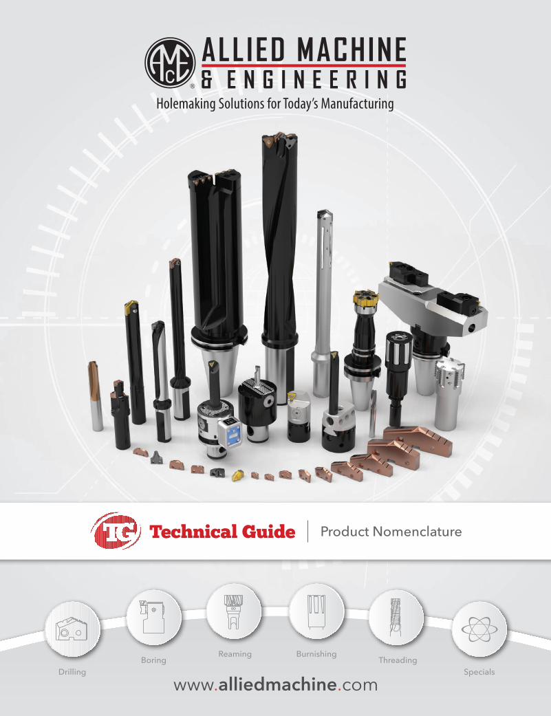
Allied Machine & Engineering is a worldwide leader in holemaking and finishing solutions. We are committed to providing practical and dependable solutions to our customers through innovative designs and superior customer and technical support.
We continue to expand our product offering in order to provide new and different solutions. With Field Sales Engineers located around the world, we position ourselves to provide technical support on site, right at your spindle.
Contents
DrillingASC 320®. . . . . . . . . . . . . . . . . . 2
GEN3SYS® XT and XT Pro. . . . . . . . . . . . . . . . . . 3
T-A® Drilling System. . . . . . . . . . . . . . . . . . 4
High Performance and Universal. . . . . . . . . . . . . . . . . . 5
APX Drill . . . . . . . . . . . . . . . . . . 6
4TEX™ Drill . . . . . . . . . . . . . . . . . . 7
Revolution Drill® & Opening Drill® . . . . . . . . . . . . . . . . . . 8
Industry SolutionsStructural Steel. . . . . . . . . . . . . . . . . . 9
AccuPort 432®. . . . . . . . . . . . . . . . . 10
ReamingALVAN® Reamers . . . . . . . . . . . . . . 11 - 13
BurnishingS.C.A.M.I.® Roller Burnishing. . . . . . . . . . . . . . . . . 14
ThreadingAccuThread™ and ThreadMills USA™. . . . . . . . . . . . . . . . . 15
Technical Guide Product Nomenclature
1

ALLIED MACHINE & ENGINEERING | NOMENCLATURE
www.alliedmachine.com | 1.330.343.4283 2
ASC 320 Solid Carbide Drills
3 60 M 07500 A21 M1 2 3 4 5 6
1. ASC 320® 2. Length 3. Style 4. Diameter 5. Substrate Geometry 6. Multi-Layer Coating
3 = Solid carbide 35 = 3.5xD E = English 07500 = 0.7500” A21 = Standard M = TiAlN
60 = 6xD (Imperial)
90 = 9xD M = Metric
ASC 320®

ALLIED MACHINE & ENGINEERING | NOMENCLATURE
www.alliedmachine.com | 1.330.343.4283 3
GEN3SYS XT Drill Inserts
7 C2 12 P - .484 CI1 2 3 4 5 6
GEN3SYS XT and XT Pro Drill Holders
HXT 03 12 S - 20 FM1 2 3 4 5 6
1. Holder 2. Length 3. Series 4. Flute
6 = XT standard holder 01 = Stub Length (standard only) 11 = 11 series 18 = 18 series S = Straight
HXT = XT Pro holder 03 = 3x Diameter 12 = 12 series 20 = 20 series H = Helical
05 = 5x Diameter 13 = 13 series 22 = 22 series C45 = Drill/Chamfer
07 = 7x Diameter 14 = 14 series 24 = 24 series (both helical and drill/chamfer options available for XT standard only)
10 = 10x Diameter (Pro only) 15 = 15 series 26 = 26 series
16 = 16 series 29 = 29 series
17 = 17 series 32 = 32 series
5. Shank Diameter 6. Shank Style
Imperial (inch) Metric (mm) F = Flanged with flat
063 = 5/8” 16 = 16mm FM = Flanged metric with flat
075 = 3/4” 20 = 20mm C = Cylindrical (no flat)
100 = 1” 25 = 25mm CM = Cylindrical metric (no flat)
125 = 1-1/4” 32 = 32mm
150 = 1-1/2” 40 = 40mm
GEN3SYS® XT and XT Pro
GEN3SYS XT Pro Drill Inserts
XT P 11 - 11.001 2 3 4
1. XT Pro Insert 2. ISO Material / Geometry 3. Series 4. Diameter (mm)
XT = XT Pro insert P = Steel 11 = 11 series 16 = 16 series 24 = 24 series For complete list of diameter ranges by series, see contents page.
K = Cast iron 12 = 12 series 17 = 17 series 26 = 26 series
N = Non-ferrous 13 = 13 series 18 = 18 series 29 = 29 series
14 = 14 series 20 = 20 series 32 = 32 series
15 = 15 series 22 = 22 series
1. XT Insert 2. Insert Material 3. Series 4. Coating
7 = XT insert C1 = C1 (K35) 11 = 11 series 16 = 16 series 24 = 24 series P = AM300®
C2 = C2 (K20) 12 = 12 series 17 = 17 series 26 = 26 series
13 = 13 series 18 = 18 series 29 = 29 series
14 = 14 series 20 = 20 series 32 = 32 series
15 = 15 series 22 = 22 series
5. Diameter 6. Geometry
0017 = Inch CI = Cast iron
.515 = Decimal LR = Low rake
13 = Metric AS = Stainless steel
ALLIED MACHINE & ENGINEERING | NOMENCLATURE
www.alliedmachine.com | 1.330.343.4283 4
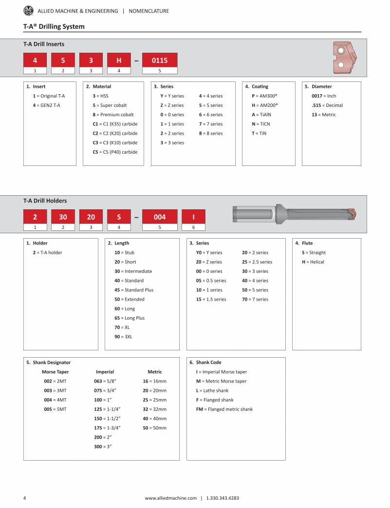
T-A® Drilling System
T-A Drill Inserts
4 5 3 H - 01151 2 3 4 5
1. Insert 2. Material
1 = Original T-A 3 = HSS
4 = GEN2 T-A 5 = Super cobalt
8 = Premium cobalt
C1 = C1 (K35) carbide
C2 = C2 (K20) carbide
C3 = C3 (K10) carbide
C5 = C5 (P40) carbide
3. Series
Y = Y series 4 = 4 series
Z = Z series 5 = 5 series
0 = 0 series 6 = 6 series
1 = 1 series 7 = 7 series
2 = 2 series 8 = 8 series
3 = 3 series
T-A Drill Holders
2 30 20 S - 004 I1 2 3 4 5 6
1. Holder 2. Length 3. Series 4. Flute
2 = T-A holder 10 = Stub Y0 = Y series 20 = 2 series S = Straight
20 = Short Z0 = Z series 25 = 2.5 series H = Helical
30 = Intermediate 00 = 0 series 30 = 3 series
40 = Standard 05 = 0.5 series 40 = 4 series
45 = Standard Plus 10 = 1 series 50 = 5 series
50 = Extended 15 = 1.5 series 70 = 7 series
60 = Long
65 = Long Plus
70 = XL
90 = 3XL
5. Shank Designator 6. Shank Code
Morse Taper Imperial Metric I = Imperial Morse taper
002 = 2MT 063 = 5/8” 16 = 16mm M = Metric Morse taper
003 = 3MT 075 = 3/4” 20 = 20mm L = Lathe shank
004 = 4MT 100 = 1” 25 = 25mm F = Flanged shank
005 = 5MT 125 = 1-1/4” 32 = 32mm FM = Flanged metric shank
150 = 1-1/2” 40 = 40mm
175 = 1-3/4” 50 = 50mm
200 = 2”
300 = 3”
4. Coating 5. Diameter
P = AM300® 0017 = Inch
H = AM200® .515 = Decimal
A = TiAlN 13 = Metric
N = TiCN
T = TiN
ALLIED MACHINE & ENGINEERING | NOMENCLATURE
www.alliedmachine.com | 1.330.343.4283 5
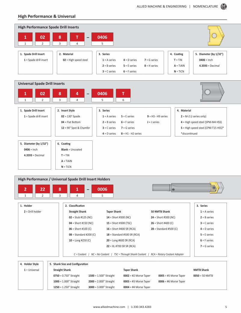
High Performance & Universal
High Performance Spade Drill Inserts
1 02 8 T - 04061 2 3 4 5
1. Spade Drill Insert 2. Material 3. Series 4. Coating 5. Diameter (by 1/32”)
1 = Spade drill insert 02 = High speed steel 1 = A series 4 = D series 7 = G series T = TiN 0406 = Inch
2 = B series 5 = E series 8 = H series A = TiAlN 4.3593 = Decimal
3 = C series 6 = F series N = TiCN
Universal Spade Drill Inserts
1 02 8 4 - 0406 T1 2 3 4 5 6
1. Spade Drill Insert 2. Insert Style 3. Series 4. Material
1 = Spade drill insert 02 = 130° Spade 1 = A series 5 = E series 9 = H3 - H9 series 2 = M-2 (J series only)
04 = Flat Bottom 2 = B series 6 = F series J = J series 4 = High speed steel (SPM-M4 HSS)
12 = 90° Spot & Chamfer 3 = C series 7 = G series 5 = High speed steel (CPM-T15 HSS)*
4 = D series 8 = H1 - H2 series *discontinued
5. Diameter (by 1/32”) 6. Coating
0406 = Inch Blank = Uncoated
4.3593 = Decimal T = TiN
A = TiAlN
N = TiCN
High Performance / Universal Spade Drill Insert Holders
2 22 8 1 - 00061 2 3 4 5
1. Holder 2. Classification 3. Series
2 = Drill holder Straight Shank Taper Shank 50 NMTB Shank 1 = A series
02 = Stub #125 (NC) 14 = Short #300 (NC) 24 = Short #300 (NC) 2 = B series
04 = Short #150 (NC) 15 = Short #300 (TSC) 26 = Short #400 (C) 3 = C series
06 = Short #100 (C) 16 = Short #400 SR (RCA) 28 = Standard #500 (C) 4 = D series
08 = Standard #200 (C) 18 = Standard #500 SR (RCA) 5 = E series
10 = Long #250 (C) 20 = Long #600 SR (RCA) 6 = F series
22 = XL #700 SR SR (RCA) 7 = G series
C = Coolant | NC = No Coolant | TSC = Through Shank Coolant | RCA = Rotary Coolant Adapter
4. Holder Style 5. Shank Size and Configuration
1 = Universal Straight Shank Taper Shank NMTB Shank
0750 = 0.750” Straight 1500 = 1.500” Straight 0002 = #2 Morse Taper 0005 = #5 Morse Taper 0050 = 50 NMTB
1000 = 1.000” Straight 2000 = 2.000” Straight 0003 = #3 Morse Taper 0006 = #6 Morse Taper
1250 = 1.250” Straight 3000 = 3.000” Straight 0004 = #4 Morse Taper
ALLIED MACHINE & ENGINEERING | NOMENCLATURE
www.alliedmachine.com | 1.330.343.4283 6
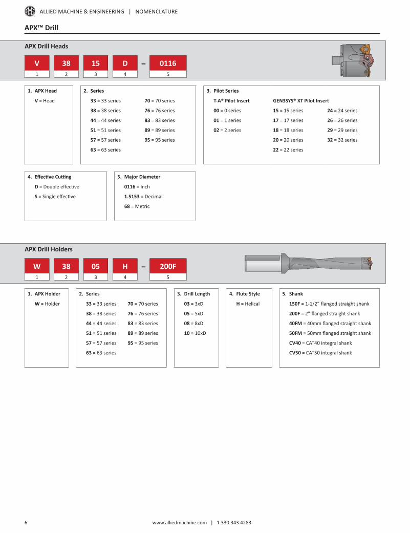
APX Drill Heads
V 38 15 D - 01161 2 3 4 5
APX™ Drill
4. Effective Cutting 5. Major Diameter
D = Double effective 0116 = Inch
S = Single effective 1.5153 = Decimal
68 = Metric
1. APX Head 2. Series
V = Head 33 = 33 series 70 = 70 series
38 = 38 series 76 = 76 series
44 = 44 series 83 = 83 series
51 = 51 series 89 = 89 series
57 = 57 series 95 = 95 series
63 = 63 series
APX Drill Holders
W 38 05 H - 200F1 2 3 4 5
1. APX Holder 2. Series 3. Drill Length 4. Flute Style 5. Shank
W = Holder 33 = 33 series 70 = 70 series 03 = 3xD H = Helical 150F = 1-1/2” flanged straight shank
38 = 38 series 76 = 76 series 05 = 5xD 200F = 2” flanged straight shank
44 = 44 series 83 = 83 series 08 = 8xD 40FM = 40mm flanged straight shank
51 = 51 series 89 = 89 series 10 = 10xD 50FM = 50mm flanged straight shank
57 = 57 series 95 = 95 series CV40 = CAT40 integral shank
63 = 63 series CV50 = CAT50 integral shank
3. Pilot Series
T-A® Pilot Insert GEN3SYS® XT Pilot Insert
00 = 0 series 15 = 15 series 24 = 24 series
01 = 1 series 17 = 17 series 26 = 26 series
02 = 2 series 18 = 18 series 29 = 29 series
20 = 20 series 32 = 32 series
22 = 22 series

ALLIED MACHINE & ENGINEERING | NOMENCLATURE
www.alliedmachine.com | 1.330.343.4283 7
4TEX Drill Holders
D4 03 1200 M - 075 F1 2 3* 4 5 6
4TEX™ Drill
5. Shank Diameter 6. Shank Style
Imperial Metric F = Imperial flanged shank
075 = .075” 20 = 20mm FM = Metric flanged shank
100 = 1.000” 25 = 25mm
125 = 1.250” 32 = 32mm
150 = 1.500” 40 = 40mm
1. Length to Diameter Ratio 2. Series 3. Diameter* 4. Diameter Style
D2 = 2xD 03 = 03 series 07 = 07 series 0750 = .075” I = Imperial
D3 = 3xD 04 = 04 series 09 = 09 series 1200 = 12mm M = Metric
D4 = 4xD 05 = 05 series 11 = 11 series
06 = 06 series 14 = 14 series
ALLIED MACHINE & ENGINEERING | NOMENCLATURE
www.alliedmachine.com | 1.330.343.4283 8
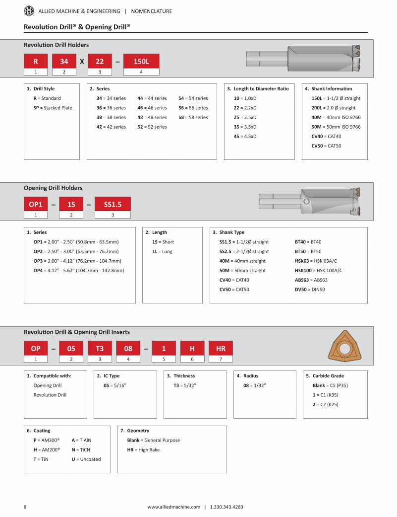
Revolution Drill Holders
R 34 X 22 - 150L1 2 3 4
1. Drill Style 2. Series
R = Standard 34 = 34 series 44 = 44 series 54 = 54 series
SP = Stacked Plate 36 = 36 series 46 = 46 series 56 = 56 series
38 = 38 series 48 = 48 series 58 = 58 series
42 = 42 series 52 = 52 series
Revolution Drill & Opening Drill Inserts
OP - 05 T3 08 - 1 H HR1 2 3 4 5 6 7
1. Compatible with: 2. IC Type 3. Thickness 4. Radius 5. Carbide Grade
Opening Drill 05 = 5/16” T3 = 5/32” 08 = 1/32” Blank = C5 (P35)
Revolution Drill 1 = C1 (K35)
2 = C2 (K25)
3. Length to Diameter Ratio 4. Shank Information
10 = 1.0xD 150L = 1-1/2 Ø straight
22 = 2.2xD 200L = 2.0 Ø straight
25 = 2.5xD 40M = 40mm ISO 9766
35 = 3.5xD 50M = 50mm ISO 9766
45 = 4.5xD CV40 = CAT40
CV50 = CAT50
Revolution Drill® & Opening Drill®
6. Coating 7. Geometry
P = AM300® A = TiAlN Blank = General Purpose
H = AM200® N = TiCN HR = High Rake
T = TiN U = Uncoated
Opening Drill Holders
OP1 - 1S - SS1.51 2 3
1. Series 2. Length 3. Shank Type
OP1 = 2.00” - 2.50” (50.8mm - 63.5mm) 1S = Short SS1.5 = 1-1/2Ø straight BT40 = BT40
OP2 = 2.50” - 3.00” (63.5mm - 76.2mm) 1L = Long SS2.5 = 2-1/2Ø straight BT50 = BT50
OP3 = 3.00” - 4.12” (76.2mm - 104.7mm) 40M = 40mm straight HSK63 = HSK 63A/C
OP4 = 4.12” - 5.62” (104.7mm - 142.8mm) 50M = 50mm straight HSK100 = HSK 100A/C
CV40 = CAT40 ABS63 = ABS63
CV50 = CAT50 DV50 = DIN50

ALLIED MACHINE & ENGINEERING | NOMENCLATURE
www.alliedmachine.com | 1.330.343.4283 9
GEN3SYS XT Pro Drill Inserts
XT ST 20 - 20.001 2 3 4
1. XT Pro Drill Insert 2. Geometry 3. Series 4. Diameter (mm)
XT = XT Pro insert ST = Structural Steel 12 = 12 series 16 = 16 series 20 = 20 series 26 = 26 series For complete list of diameter ranges by series, see contents page.
13 = 13 series 17 = 17 series 22 = 22 series 29 = 29 series
14 = 14 series 18 = 18 series 24 = 24 series 32 = 32 series
15 = 15 series
Structural Steel Solutions
GEN3SYS XT Structural Steel Drill Holders
ST 03 12 0 - 20 FM1 2 3 4 5 6
1. Holder 2. Length 3. Series 4. Body Diameter
ST = Structural holder 03 = 3x Diameter 12 = 12 series 16 = 16 series 20 = 20 series 26 = 26 series 0 = Standard
05 = 5x Diameter 13 = 13 series 17 = 17 series 22 = 22 series 29 = 29 series 5 = Oversized
07 = 7x Diameter 14 = 14 series 18 = 18 series 24 = 24 series 32 = 32 series
15 = 15 series
5. Shank Diameter 6. Shank Style
Imperial (in) Metric (mm) F = Flanged with flat
063 = 5/8” 125 = 1-1/4” 16 = 16mm 32 = 32mm FM = Flanged metric with flat
075 = 3/4” 150 = 1-1/2” 20 = 20mm 40 = 40mm C = Cylindrical (no flat)
100 = 1” 25 = 25mm CM = Cylindrical metric (no flat)
T-A Drill Inserts
4 5 3 H - 0115 - HE1 2 3 4 5 6
1. Insert 2. Material
1 = Original T-A 5 = Super cobalt
4 = GEN2 T-A C1 = C1 (K35) carbide
3. Series
0 = 0 series
1 = 1 series
2 = 2 series
3 = 3 series
4. Coating 5. Diameter 6. Geometry
H = AM200® 0017 = Inch TW = Thin Wall
A = TiAlN .515 = Decimal NP = Notch Point®
13 = Metric SS = Structural Steel
HE = High Efficiency
T-A Drill Holders
2 40 20 S - 004 IS 0601 2 3 4 5 6 7
1. Holder 2. Length 3. Series 4. Flute
2 = T-A holder 20 = Short 00 = 0 series 20 = 2 series S = Straight
40 = Standard 05 = 0.5 series 25 = 2.5 series H = Helical
50 = Extended 10 = 1 series 30 = 3 series
60 = Long 15 = 1.5 series
5. Shank 6. Shank Code 7. Minimum Insert Ø
003 = 3MT IS = Imperial Morse taperstructural steel
In increments of 1/64 of an inch
004 = 4MT
ALLIED MACHINE & ENGINEERING | NOMENCLATURE
www.alliedmachine.com | 1.330.343.4283 10
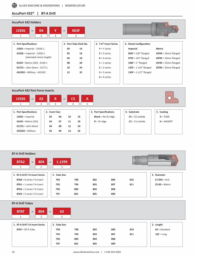
AccuPort 432® | BT-A Drill
AccuPort 432 Holders
J1926 - 04 Y - 063F1 2 3 4
1. Port Specifications 2. Port Tube Dash No. 3. T-A® Insert Series
J1926 = Imperial - J1926-1 04 14 Y = Y series
X1926 = Imperial - J1926-1 05 16 Z = Z series (extended minor length) 06 18 0 = 0 series
I6149 = Metric (ISO) - 6149-1 08 20 1 = 1 series
G1731 = John Deere - G173.1 10 24 2 = 2 series
AS5202 = Military - AS5202 12 32 3 = 3 series
4 = 4 series
4. Shank Configuration
Imperial Metric
063F = 5/8” flanged 16FM = 16mm flanged
075F = 3/4” flanged 20FM = 20mm flanged
100F = 1” flanged 25FM = 25mm flanged
125F = 1-1/4” flanged 32FM = 32mm flanged
150F = 1-1/2” flanged
AccuPort 432 Port Form Inserts
J1926 - 02 R - C5 A1 2 3 4 5
1. Port Specifications 2. Insert Size 3. Port Specifications 4. Substrate 5. Coating
J1926 = Imperial 02 06 10 16 Blank = No ID ridge C5 = C5 carbide A = TiAlN
I6149 = Metric (ISO) 03 07 11 20 R = ID ridge C3 = C3 carbide H = AM200®
G1731 = John Deere 04 08 12 24
AS5202 = Military 05 09 14 32
BT-A Drill Holders
BTA2 - 804 - 1.12991 2 3
1. BT-A Drill T-A Insert Series 2. Tube Size 3. Diameter
BTA0 = 0 series T-A insert 794 798 802 806 810 0.7344 = Inch
BTA1 = 1 series T-A insert 795 799 803 807 811 25.00 = Metric
BTA2 = 2 series T-A insert 796 800 804 808
BTA3 = 3 series T-A insert 797 801 805 809
BT-A Drill Tubes
BTAT - 804 - 631 2 3
1. BT-A Drill T-A Insert Series 2. Tube Size 3. Length
BTAT = BT-A Tube 794 798 802 806 810 63 = Standard
795 799 803 807 811 102 = Long
796 800 804 808
797 801 805 809

ALLIED MACHINE & ENGINEERING | NOMENCLATURE
www.alliedmachine.com | 1.330.343.4283 11
Monobloc Style Reamers
I 9 2440 - KL E - 006250 + 0000 - 00051 2 3 4 5 6 7
NOTE: If diameter and tolerance are specified in inch units, put an “I” at the beginning of the item number
1. Units of Measure 2. Shank Measure 3. Series
Blank = Metric diameter Blank = Metric 2440 = Short length, straight flute - no coolant
I = Inch diameter 9 = Inch 2441 = Short length, straight flute - central coolant (blind holes)
3620 = Short length, straight flute - radial coolant (through holes)
3627 = Short length, helical flute - radial coolant (through holes)
2430 = Long length, straight flute - no coolant
2431 = Long length, straight flute - central coolant (blind holes)
3610 = Long length, straight flute - radial coolant (through holes)
3617 = Long length, helical flute - radial coolant (through holes)
Reamers: Monobloc Style | Cutting Rings
4. Coating and Substrate 5. Lead-in
KL = Uncoated carbide SV = Uncoated cermet E, M, K = Left hand helical flute
KN = TiN coated carbide SN = TiN coated cermet A, F, G, L, N, T, V = Straight flute
KC = TiCN coated carbide SC = TiCN coated cermet J, W, X, Y = Straight flute with chipbreaker
KA = TiAlN coated carbide SA = TiAlN coated cermet
KK = Alcrona coated carbide SK = Alcrona coated cermet
6. Diameter 7. Tolerance*
XX.XXXX = Imperial (inch) 4 decimal places = inch tolerance
XXX.XXX = Metric (mm) 3 decimal places = mm tolerance
*The total tolerance capable is 0.0002” (0.005mm)
Cutting Rings
I - 2ANC-KT F - 019686 + 0000 - 00051 2 3 4 5
NOTE: If diameter and tolerance are specified in inch units, put an “I” at the beginning of the item number
1. Cutting Ring 2. Coating and Substrate
Blank = Metric diameter 2000-KT = Uncoated carbide 2AVC-ST = Uncoated cermet
I = Inch diameter 2TIN-KT = TiN coated carbide 2ANC-ST = TiN coated cermet
2TIC-KT = TiCN coated carbide 2ACC-ST = TiCN coated cermet
2TIA-KT = TiAlN coated carbide 2AAC-ST = TiAlN coated cermet
2TLK-KT = Alcrona coated carbide 2ALK-ST = Alcrona coated cermet
3. Lead-in 4. Diameter 5. Tolerance
E, M, K = Left hand helical flute XX.XXXX = Inch 4 decimal places = inch tolerance
A, F, G, L, N, T, V = Straight flute XXX.XXX = Metric 3 decimal places = mm tolerance
J, W, X, Y = Straight Flute with chipbreaker
*The total tolerance capable is 0.0002” (0.005mm)
ALLIED MACHINE & ENGINEERING | NOMENCLATURE
www.alliedmachine.com | 1.330.343.4283 12
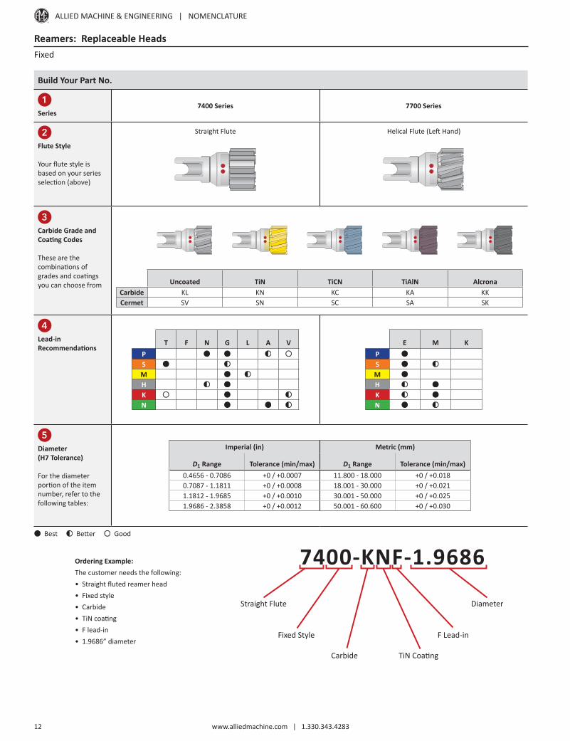
Reamers: Replaceable Heads
Build Your Part No.
1Series
7400 Series 7700 Series
2Flute Style
Your flute style is based on your series selection (above)
Straight Flute Helical Flute (Left Hand)
3Carbide Grade andCoating Codes
These are the combinations of grades and coatings you can choose from Uncoated TiN TiCN TiAlN Alcrona
Carbide KL KN KC KA KKCermet SV SN SC SA SK
4Lead-in Recommendations
T F N G L A VPSMHKN
E M KPSMHKN
5Diameter(H7 Tolerance)
For the diameter portion of the item number, refer to the following tables:
Imperial (in) Metric (mm)
D1 Range Tolerance (min/max) D1 Range Tolerance (min/max)0.4656 - 0.7086 +0 / +0.0007 11.800 - 18.000 +0 / +0.0180.7087 - 1.1811 +0 / +0.0008 18.001 - 30.000 +0 / +0.0211.1812 - 1.9685 +0 / +0.0010 30.001 - 50.000 +0 / +0.0251.9686 - 2.3858 +0 / +0.0012 50.001 - 60.600 +0 / +0.030
Ordering Example:The customer needs the following:• Straight fluted reamer head• Fixed style• Carbide• TiN coating• F lead-in• 1.9686” diameter
7400-KNF-1.9686
Straight Flute
Carbide
F Lead-in
Diameter
Fixed Style
TiN Coating
Fixed
Best Better Good
ALLIED MACHINE & ENGINEERING | NOMENCLATURE
www.alliedmachine.com | 1.330.343.4283 13
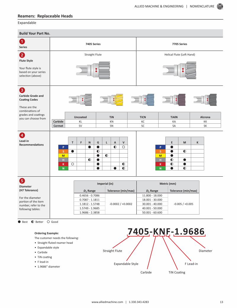
Reamers: Replaceable Heads
Build Your Part No.
1Series
7405 Series 7705 Series
2Flute Style
Your flute style is based on your series selection (above)
Straight Flute Helical Flute (Left Hand)
3Carbide Grade andCoating Codes
These are the combinations of grades and coatings you can choose from Uncoated TiN TiCN TiAlN Alcrona
Carbide KL KN KC KA KKCermet SV SN SC SA SK
4Lead-in Recommendations
T F N G L A VPSMHKN
E M KPSMHKN
5Diameter(H7 Tolerance)
For the diameter portion of the item number, refer to the following tables:
Imperial (in) Metric (mm)
D1 Range Tolerance (min/max) D1 Range Tolerance (min/max)0.4656 - 0.7086
-0.0002 / +0.0002
11.800 - 18.000
-0.005 / +0.0050.7087 - 1.1811 18.001 - 30.0001.1812 - 1.5748 30.001 - 40.0001.5749 - 1.9685 40.001 - 50.0001.9686 - 2.3858 50.001 - 60.600
Ordering Example:The customer needs the following:• Straight fluted reamer head• Expandable style• Carbide• TiN coating• F lead-in• 1.9686” diameter
7405-KNF-1.9686
Straight Flute
Carbide
F Lead-in
Diameter
Expandable Style
TiN Coating
Expandable
Best Better Good

ALLIED MACHINE & ENGINEERING | NOMENCLATURE
www.alliedmachine.com | 1.330.343.4283 14
Roller Burnishing Tools
RDK H - 2 1 0 - 004,701 2 3 4 5 6
1. Type of Burnisher 2. Series 3. Shank Type
RDK = Through holes H = H series F = F series P = P series T = T series 1 = Straight
RSK = Blind holes I = I series M = M series Q = Q series U = U series 2 = Morse Taper
K = K series N = N series R = R series
L = L series O = O series S = S series
Roller Burnishing
4. Length 5. Cage Style 6. Diameter
0 = Unlimited 0 = Standard Through Hole Tools = Minimum diameter of burnishing range
1 = Short Blind Hole Tools = Diameter to burnish
2 = Standard
3 = Long
ALLIED MACHINE & ENGINEERING | NOMENCLATURE
www.alliedmachine.com | 1.330.343.4283 15
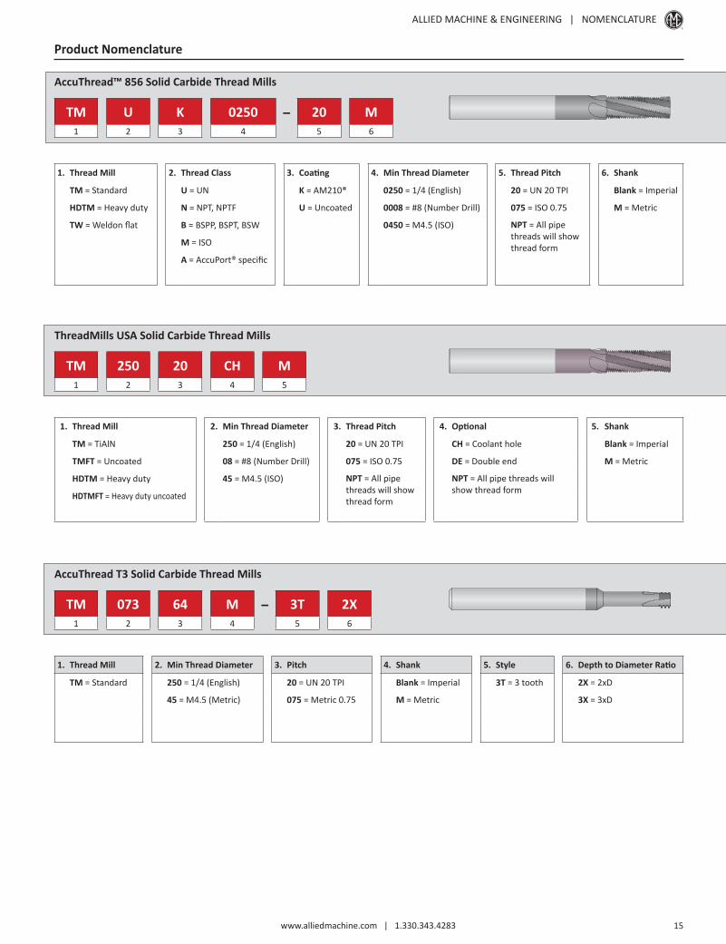
AccuThread™ 856 Solid Carbide Thread Mills
TM U K 0250 - 20 M1 2 3 4 5 6
1. Thread Mill 2. Thread Class 3. Coating 4. Min Thread Diameter 5. Thread Pitch 6. Shank
TM = Standard U = UN K = AM210® 0250 = 1/4 (English) 20 = UN 20 TPI Blank = Imperial
HDTM = Heavy duty N = NPT, NPTF U = Uncoated 0008 = #8 (Number Drill) 075 = ISO 0.75 M = Metric
TW = Weldon flat B = BSPP, BSPT, BSW 0450 = M4.5 (ISO) NPT = All pipethreads will showthread formM = ISO
A = AccuPort® specific
Product Nomenclature
ThreadMills USA Solid Carbide Thread Mills
TM 250 20 CH M1 2 3 4 5
1. Thread Mill 2. Min Thread Diameter 3. Thread Pitch 4. Optional 5. Shank
TM = TiAlN 250 = 1/4 (English) 20 = UN 20 TPI CH = Coolant hole Blank = Imperial
TMFT = Uncoated 08 = #8 (Number Drill) 075 = ISO 0.75 DE = Double end M = Metric
HDTM = Heavy duty 45 = M4.5 (ISO) NPT = All pipethreads will showthread form
NPT = All pipe threads willshow thread formHDTMFT = Heavy duty uncoated
AccuThread T3 Solid Carbide Thread Mills
TM 073 64 M - 3T 2X1 2 3 4 5 6
1. Thread Mill 2. Min Thread Diameter 3. Pitch 4. Shank 5. Style 6. Depth to Diameter Ratio
TM = Standard 250 = 1/4 (English) 20 = UN 20 TPI Blank = Imperial 3T = 3 tooth 2X = 2xD
45 = M4.5 (Metric) 075 = Metric 0.75 M = Metric 3X = 3xD

ALLIED MACHINE & ENGINEERING | NOMENCLATURE
www.alliedmachine.com | 1.330.343.4283 16
Notes

Warranty Information
Allied Machine & Engineering warrants to original equipment manufacturers, distributors, industrial and commercial users of its products that each new product manufactured or supplied by Allied Machine shall be free from defects in material and workmanship.
Allied Machine’s obligation under this warranty is limited to furnishing without additional charge a replacement or, at its option repairing or issuing credit for any product which shall within one year from the date of sale be returned freight prepaid to the plant designated by an Allied Machine representative and which upon inspection is determined by Allied Machine to be defective in materials or workmanship.
Complete information as to operating conditions, machine, set-up, and application of cutting fluid should accompany any product returned for inspection. The provisions of this warranty shall not apply to any Allied Machine products which have been subjected to misuse, improper operating conditions, machine set-up or application of cutting fluid or which have been repaired or altered if such repair or alteration in the judgment of Allied Machine would adversely affect performance of the product.
THIS WARRANTY IS IN LIEU OF ALL OTHER WARRANTIES, EXPRESS OR IMPLIED, INCLUDING ANY IMPLIED WARRANTY OF MERCHANTABILITY OR FITNESS FOR A PARTICULAR PURPOSE. Allied Machine shall have no liability or responsibility on any claim of any kind, whether in contract, tort or otherwise, for any loss or damage arising out of, connected with, or resulting from the manufacture, sale, delivery or use of any product sold hereunder, in excess of the cost of replacement or repair as provided herein.
ALL PRICES, DELIVERIES, DESIGNS, AND MATERIALS ARE SUBJECT TO CHANGE WITHOUT NOTICE.
Allied Machine & Engineering Registered to ISO 9001
10001329
United StatesAllied Machine & Engineering120 Deeds DriveDover OH 44622United States
Phone:+1.330.343.4283
Toll Free USA and Canada:800.321.5537
Fax:+1.330.602.3400
Toll Free USA and Canada:800.223.5140
Allied Machine & Engineering485 W Third StreetDover OH 44622United States
Phone:+1.330.343.4283
Toll Free USA and Canada:800.321.5537
Fax:+1.330.364.7666(Engineering Dept.)
EuropeAllied Machine & Engineering Co. (Europe) Ltd.93 Vantage PointPensnett EstateKingswinfordWest MidlandsDY6 7FR England
Phone:+44 (0) 1384.400900
Wohlhaupter GmbHMaybachstrasse 4Postfach 126472636 FrickenhausenGermany
Phone:+49 (0) 7022.408.0
Fax:+49 (0) 7022.408.212
AsiaWohlhaupter India Pvt. Ltd.B-23, 2nd FloorB Block Community CentreJanakpuri, New Delhi - 110058India
Phone:+91 (0) 11.41827044
Your local Allied Machine representative:
www.alliedmachine.comAllied Machine & Engineering is registered by DQS to ISO 9001 10001329
© 2018 Allied Machine & EngineeringAvailable Online Only: TG-NOM
Publish Date: October 2018


![Allied Telesyn Government Allied Telesyn Centrecom Manual[1]](https://img.pdfslide.us/doc/110x75/547ef4015806b5d15e8b47a8/allied-telesyn-government-allied-telesyn-centrecom-manual1.jpg)