Embed Size (px)
Citation preview
TechnicalInformation
Fieldbus Technical Information
TI 38K03A01-01E
TI 38K03A01-01E©Copyright Mar. 1998(YK)4th Edition Mar. 2012(YK)
Yokogawa Electric Corporation2-9-32, Nakacho, Musashino-shi, Tokyo, 180-8750 JapanTel.: 81-422-52-5634 Fax.: 81-422-52-9802

Blank Page
i
TI 38K03A01-01E
IntroductionFieldbus has been well-adopted among users and manufacturers of industrial automation and it is creating the digital network era in the 21st century.This document introduces users how to apply fieldbus technologies in their process control systems, along with Plant Resource Manager (PRM), Yokogawa’s plant asset management software package, for offering Yokogawa’s fieldbus solutions in the field digital era.
Document structureThis document consists of three parts as shown below and provides an overview of Yokogawa’s fieldbus solutions, and explains the benefits of adopting them. Part A: Overview of fieldbus and Yokogawa’s fieldbus-ready products A1 Progress of international standardization of fieldbus A2 Features of fieldbus A3 FOUNDATION fieldbus-compliant devices A4 Yokogawa’s fieldbus-ready host systemsPart B: Fieldbus engineering B1 Managing fieldbus engineering B2 System design considerations B3 Installation guidance B4 Starting up the system B5 System maintenancePart C: Overview of Plant Resource Manager (PRM) C1 Overview of Plant Resource Manager (PRM) C2 PRM system configuration
Mar. 30, 2012-00All Rights Reserved Copyright © 1998, Yokogawa Electric Corporation
ii
TI 38K03A01-01E
Target readership • Managers who are planning to purchase a production control system with field digital network
and a plant asset management such as PRM.
• Instrument, electric, maintenance, and computer engineers who are evaluating production control systems, fieldbus, and maintenance management systems or being involved in installations and maintenance of these systems.
Trademarks• CENTUM, Vnet/IP, and ProSafe are registered trademark of Yokogawa Electric Corporation.
• PRM is a registered trademark of Yokogawa Electric Corporation.
• STARDOM is a trademark.
• Ethernet is a registered trademark of Xerox Corporation.
• Microsoft and Windows are registered trademarks or trademarks of Microsoft Corporation in the United States and/or other countries.
• “FOUNDATION” in “FOUNDATION fieldbus” is a trademark of the Fieldbus Foundation.
• NI-FBUS Monitor is a registered trademark of National Instruments Corporation.
• HART is a registered trademark of the HART Communication Foundation.
• MAXIMO is a registered trademark of IBM.
• Other product and company names may be registered trademarks of their respective companies (™ or ® mark is not displayed).
Mar. 30, 2012-00
TocA-1
TI 38K03A01-01E
Fieldbus Technical InformationPart A Overview of Fieldbus and Yokogawa’s Fieldbus-ready Products
CONTENTS
TI 38K03A01-01E 4th Edition
Mar. 30, 2012-00
A1. Progress of international standardization of fieldbus .......................A1-1A1.1 What is fieldbus? ........................................................................................... A1-1A1.2 Standardization of fieldbus ........................................................................... A1-2A1.3 Fieldbus standard specifications ................................................................. A1-4
A2. Features of fieldbus ...............................................................................A2-1A2.1 Comparison with conventional communication ....................................... A2-2A2.2 Reduced wiring cost ...................................................................................... A2-3A2.3 Improving transmission accuracy ............................................................... A2-5A2.4 Advanced data transmission ........................................................................ A2-6A2.5 Functional distributions ................................................................................ A2-7A2.6 Interoperability ............................................................................................... A2-8
A3. FOUNDATION fieldbus-compliant devices ...................................................A3-1A3.1 Changes in transmitters ................................................................................ A3-3
A3.1.1 Accuracy improvement brought by digitalization .............................A3-4
A3.1.2 Multi-sensing function ......................................................................A3-6
A3.1.3 Multiple function sensors .................................................................A3-7
A3.2 Actuator .......................................................................................................... A3-8A3.3 Using self-diagnostics function ................................................................. A3-10
A4. Yokogawa’s fieldbus-ready host systems ...........................................A4-1A4.1 CENTUM supports fieldbus .......................................................................... A4-1A4.2 Connecting third-party devices with CENTUM systems ........................... A4-2

Blank Page
A1. Progress of international standardization of fieldbus A1-1
TI 38K03A01-01E
A1. Progress of international standardization of fieldbus
This section describes about what is fieldbus, the standardization of fieldbus, fieldbus standard specifications, and Yokogawa’s contributions in standardizing fieldbus.
A1.1 What is fieldbus?The Fieldbus Foundation defined fieldbus as “a digital, two-way, multi-drop communication link among intelligent measurement and control devices.” Fieldbus has been replacing analog 4-to-20 mA DC signal standard signals used to transmit control and measurement data between a control room and plant floors. It is one of the several local area networks dedicated for industrial automation.
Industries in the 21st century cannot survive without digital information technologies and networks. From production lines to an enterprise level, the digital communication supports all the economic and social activities. Fieldbus is at the bottom of the hierarchy and exchanges information with higher-level databases.
International Electrotechnical Commission (IEC) standardized the following seven protocols as international standards of fieldbus:
• FOUNDATION™ fieldbus and HSE
• ControlNet
• PROFIBUS and PROFInet
• P-NET
• WorldFIP
• INTERBUS
• SwiftNet
FOUNDATION fieldbus is a standard defined by the Fieldbus Foundation. Yokogawa contributed in developing the fieldbus standards being a member of the board of directors of the Fieldbus Foundation from the time it was formed.
Yokogawa considers that FOUNDATION fieldbus will be used widely for process control systems in industries. Yokogawa’s CENTUM VP and CENTUM CS 3000 integrated production control systems support FOUNDATION fieldbus.
FOUNDATION fieldbus H1 (low speed voltage mode) is called FOUNDATION fieldbus, fieldbus, H1 fieldbus, or FF-H1 in this document.
The sophisticated communication functions of fieldbus enable distribution of process control via field devices and optimize those controls by interacting with field control stations (FCSs).
Mar. 30, 2012-00
A1. Progress of international standardization of fieldbus A1-2
TI 38K03A01-01E
A1.2 Standardization of fieldbusThe international standards of Fieldbus have been unified by International Electrotechnical Commission/Technical Committee 65/Sub-Committee 65C/Working Group 6 (IEC/TC65/SC65C WG6), The International Society for Measurement & Control (ISA) SP50 Committee which defined analog 4-to-20 mA DC signal as the standard electronic instrumentation signal, and the Fieldbus Foundation.
Establishment of the Fieldbus FoundationIn August, 1992, Yokogawa organized the Interoperable Systems Project (ISP) in association with Fisher Control, Rosemount, and Siemens. In February, 1993, ISP became ISP Association. In March, 1993, World Factory Instrumentation Protocol (WorldFIP) was organized by Honeywell, Allen-Bradley, CEGELEC, Telemechanique, and several other companies.
A consensus was then obtained amongst customers that the fieldbus should conform to the internationally unified standard. In September, 1994, the ISP Association and the WorldFIP North America were merged to form the Fieldbus Foundation. Yokogawa is the board member since its establishment and has been promoting the FOUNDATION fieldbus worldwide.
Mar. 30, 2012-00
A1. Progress of international standardization of fieldbus A1-3
TI 38K03A01-01E
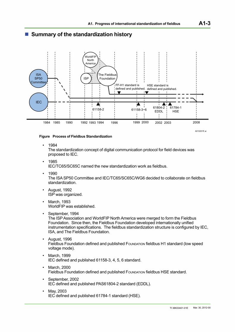
Summary of the standardization history
A010201E.ai
1985 1990 1992 1993 1994 19961984
The FieldbusFoundationISP
WorldFIPNorth
America
IEC
ISASP50
Committee
1999 2000 2002 2003 2008
61158-2 61158-3~661804-2EDDL
61784-1HSE
FF-H1 standard is defined and published.
HSE standard isdefined and published.
Figure Process of Fieldbus Standardization
• 1984 The standardization concept of digital communication protocol for field devices was proposed to IEC.
• 1985 IEC/TC65/SC65C named the new standardization work as fieldbus.
• 1990 The ISA SP50 Committee and IEC/TC65/SC65C/WG6 decided to collaborate on fieldbus standardization.
• August, 1992 ISP was organized.
• March, 1993 WorldFIP was established.
• September, 1994 The ISP Association and WorldFIP North America were merged to form the Fieldbus Foundation. Since then, the Fieldbus Foundation developed internationally unified instrumentation specifications. The fieldbus standardization structure is configured by IEC, ISA, and The Fieldbus Foundation.
• August, 1996 Fieldbus Foundation defined and published FOUNDATION fieldbus H1 standard (low speed voltage mode).
• March, 1999 IEC defined and published 61158-3, 4, 5, 6 standard.
• March, 2000 Fieldbus Foundation defined and published FOUNDATION fieldbus HSE standard.
• September, 2002 IEC defined and published PAS61804-2 standard (EDDL).
• May, 2003 IEC defined and published 61784-1 standard (HSE).
Mar. 30, 2012-00
A1. Progress of international standardization of fieldbus A1-4
TI 38K03A01-01E
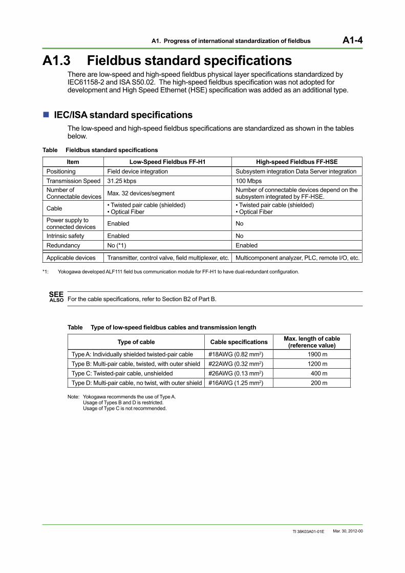
A1.3 Fieldbus standard specificationsThere are low-speed and high-speed fieldbus physical layer specifications standardized by IEC61158-2 and ISA S50.02. The high-speed fieldbus specification was not adopted for development and High Speed Ethernet (HSE) specification was added as an additional type.
IEC/ISA standard specificationsThe low-speed and high-speed fieldbus specifications are standardized as shown in the tables below.
Table Fieldbus standard specifications
Item Low-Speed Fieldbus FF-H1 High-speed Fieldbus FF-HSE Positioning Field device integration Subsystem integration Data Server integration Transmission Speed 31.25 kbps 100 Mbps Number of Connectable devices Max. 32 devices/segment Number of connectable devices depend on the
subsystem integrated by FF-HSE.
Cable • Twisted pair cable (shielded)• Optical Fiber
• Twisted pair cable (shielded) • Optical Fiber
Power supply to connected devices Enabled No
Intrinsic safety Enabled No Redundancy No (*1) Enabled
Applicable devices Transmitter, control valve, field multiplexer, etc. Multicomponent analyzer, PLC, remote I/O, etc.
*1: Yokogawa developed ALF111 field bus communication module for FF-H1 to have dual-redundant configuration.
SEE ALSO For the cable specifications, refer to Section B2 of Part B.
Table Type of low-speed fieldbus cables and transmission length
Type of cable Cable specifications Max. length of cable (reference value)
Type A: Individually shielded twisted-pair cable #18AWG (0.82 mm2) 1900 m Type B: Multi-pair cable, twisted, with outer shield #22AWG (0.32 mm2) 1200 m Type C: Twisted-pair cable, unshielded #26AWG (0.13 mm2) 400 m Type D: Multi-pair cable, no twist, with outer shield #16AWG (1.25 mm2) 200 m
Note: Yokogawa recommends the use of Type A. Usage of Types B and D is restricted. Usage of Type C is not recommended.
Mar. 30, 2012-00
A2. Features of fieldbus A2-1
TI 38K03A01-01E
A2. Features of fieldbusFieldbus is a bidirectional digital communication protocol for field devices. The fieldbus technology changed process control systems drastically and is gradually replacing the standard analog 4-to-20 mA DC signal that conventional types of field devices employ.
The FOUNDATION fieldbus has the following features :
• Costs for cables and wiring are reduced because multiple devices can be connected and multivariable transmission of device parameters is enabled on a single cable.
• A digital transmission protocol ensures accurate information processing, which enables strict quality control.
• Multiplex communications allows field devices to transmit parameters other than process variables (PVs) and manipulated variables (MVs).
• Communications among the field devices are established so that the autonomous distributed control by the field devices is enabled.
• Field devices are interoperable so that the devices from multiple vendors can be adopted.
• The interoperability provides users to select instruments from wider varieties, thus it allows an optimum system configuration.
• Integration among different systems can be established such as instrumentation and control systems, electrical equipment, factory automation (FA), building automation (BA), office automation (OA), and analyzers.
• A part of the field device adjustment and inspection works can be performed from the control room.
The rest of the pages in this section explain the advantages of the FOUNDATION fieldbus and how FOUNDATION fieldbus influences the production control systems.
Mar. 30, 2012-00
A2. Features of fieldbus A2-2
TI 38K03A01-01E
A2.1 Comparison with conventional communication
The fieldbus communication protocol is superior to analog transmissions and hybrid communications in information accuracy, transmission speed, and transmission data volume. It also offers functional superiority such as communication among field devices and bi-directional communications are established.
Analog transmissionAn analog transmission transmits information by analog 4-to-20 mA DC signal. The point-to-point topology allows only one field device to be connected to a single cable, with one-way communication. Two independent cables are required for establishing communication between a field device and a control system: one is to acquire information from the field device, and the other is to transmit control signals to the field device.
Hybrid communicationA hybrid communication transmits field device information by a combination of conventional analog 4-to-20 mA DC signal and digital signal. In addition to the analog transmission function, the field device’s span and zero-point adjustments can be remotely performed. Maintenance information such as self-diagnostics of the field device can also be obtained using a dedicated terminal.However, hybrid communication protocols have been developed independently by vendors, and the devices from different vendors are unable to exchange information with each other. It means that Yokogawa’s BRAIN system cannot exchange self-diagnostics and other device information with the third-party devices via hybrid communication method. Although the digital data communication is available with the hybrid communication, however, 4-to-20 mA DC transmission is still the dominating communication method. Therefore, the digital data communication speed of the hybrid communication is slower than that of the fieldbus communication.
Fieldbus communicationThe fieldbus communication supports fully digitalized signals unlike analog transmission or hybrid communication. It performs bi-directional communication, which allows various types and massive amounts of data transmission than analog transmission and hybrid communication.
Multiple field devices can be connected to a single fieldbus cable. Since the FOUNDATION fieldbus is internationally standardized, interoperability of field devices is guaranteed.
Fieldbus solves the problems with hybrid communications, such as slow digital transmission speeds and lack of interoperability of field devices from various vendors.
A comparison among the conventional 4-to-20 mA DC analog transmission, the hybrid communication, and the fieldbus communication protocols is as shown below.
Table Comparison of Communication Protocols
FOUNDATION fieldbus Hybrid (HART) Analog Topology Multi-drop Point-to-point Point-to-point
Transmission method Digital signal Analog 4-to-20 mA DC signal + digital signal Analog 4-to-20 mA DC signal
Transmission direction Bi-directional One-way (analog signal), Bi-directional (digital signal) One-way
Signal type Multiplex Partially multiplex Single
Mar. 30, 2012-00
A2. Features of fieldbus A2-3
TI 38K03A01-01E
A2.2 Reduced wiring costThe introduction of the fieldbus reduces wiring cost by means of multi-drop connections and multivariable transmission.
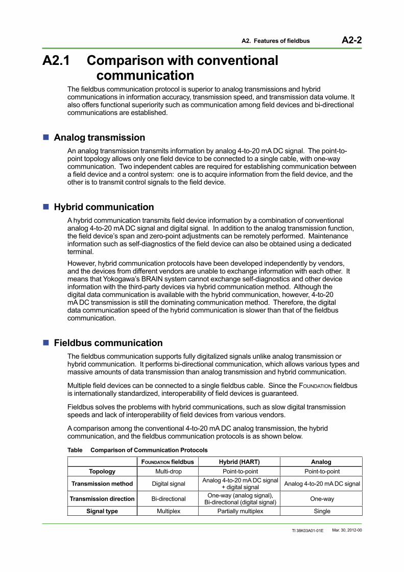
Multi-drop connectionsMulti-drop connection is to connect multiple field devices to a single cable, and the reduction of cables brings a lot of advantages. Here is an example of a multi-drop connection as shown below.
Fieldbus Multi-drop connection
Field device
To the control system
A020201E.ai
Figure Multi-drop Connections
In an analog transmission system, only one field device can be connected to a single cable that leads to a system. The multi-drop connection allows multiple field devices to be connected to a single cable. Where there is a cable already laid, additional field devices can be connected later.
In the past, the multi-drop connection of field devices was costly. With introduction of the multi-drop connection of the fieldbus communication system, more field devices can be connected to a single fieldbus without increasing the wiring cost. It gives scalability to the production control system configuration, which leads into advancement of the plant automation.
Mar. 30, 2012-00
A2. Features of fieldbus A2-4
TI 38K03A01-01E
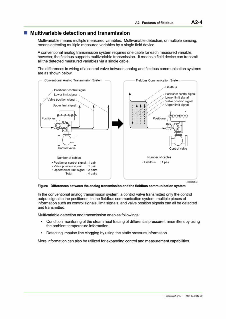
Multivariable detection and transmissionMultivariable means multiple measured variables. Multivariable detection, or multiple sensing, means detecting multiple measured variables by a single field device.
A conventional analog transmission system requires one cable for each measured variable; however, the fieldbus supports multivariable transmission. It means a field device can transmit all the detected measured variables via a single cable.
The differences in wiring of a control valve between analog and fieldbus communication systems are as shown below.
Conventional Analog Transmission System Fieldbus Communication System
Positioner Positioner
Control valve
• Positioner control signal• Valve position signal• Upper/lower limit signal Total
Control valve
Number of cables• Fieldbus : 1 pair
Number of cables
: 1 pair: 1 pair: 2 pairs: 4 pairs
A020202E.ai
Positioner control signalLower limit signalValve position signalUpper limit signal
Positioner control signalLower limit signal
Valve position signal
Upper limit signal
Fieldbus
Figure Differences between the analog transmission and the fieldbus communication system
In the conventional analog transmission system, a control valve transmitted only the control output signal to the positioner. In the fieldbus communication system, multiple pieces of information such as control signals, limit signals, and valve position signals can all be detected and transmitted.
Multivariable detection and transmission enables followings:• Condition monitoring of the steam heat tracing of differential pressure transmitters by using
the ambient temperature information.
• Detecting impulse line clogging by using the static pressure information.
More information can also be utilized for expanding control and measurement capabilities.
Mar. 30, 2012-00
A2. Features of fieldbus A2-5
TI 38K03A01-01E
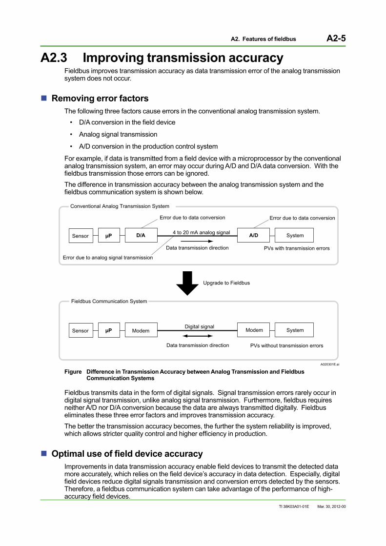
A2.3 Improving transmission accuracyFieldbus improves transmission accuracy as data transmission error of the analog transmission system does not occur.
Removing error factorsThe following three factors cause errors in the conventional analog transmission system.
• D/A conversion in the field device
• Analog signal transmission
• A/D conversion in the production control system
For example, if data is transmitted from a field device with a microprocessor by the conventional analog transmission system, an error may occur during A/D and D/A data conversion. With the fieldbus transmission those errors can be ignored.The difference in transmission accuracy between the analog transmission system and the fieldbus communication system is shown below.
Upgrade to Fieldbus
Data transmission direction
Data transmission direction
4 to 20 mA analog signal
Digital signal
PVs with transmission errors
Sensor µP ModemModem
Conventional Analog Transmission System
Fieldbus Communication System
System
PVs without transmission errors
System
Sensor µP A/DD/A
A020301E.ai
Error due to data conversionError due to data conversion
Error due to analog signal transmission
Figure Difference in Transmission Accuracy between Analog Transmission and Fieldbus Communication Systems
Fieldbus transmits data in the form of digital signals. Signal transmission errors rarely occur in digital signal transmission, unlike analog signal transmission. Furthermore, fieldbus requires neither A/D nor D/A conversion because the data are always transmitted digitally. Fieldbus eliminates these three error factors and improves transmission accuracy.The better the transmission accuracy becomes, the further the system reliability is improved, which allows stricter quality control and higher efficiency in production.
Optimal use of field device accuracyImprovements in data transmission accuracy enable field devices to transmit the detected data more accurately, which relies on the field device’s accuracy in data detection. Especially, digital field devices reduce digital signals transmission and conversion errors detected by the sensors. Therefore, a fieldbus communication system can take advantage of the performance of high-accuracy field devices.
Mar. 30, 2012-00
A2. Features of fieldbus A2-6
TI 38K03A01-01E
A2.4 Advanced data transmissionIn a fieldbus communication system, many pieces of field information as well as PVs and MVs can be exchanged in between field devices and production control systems, and among field devices. By using the fieldbus massive amounts of data can be transmitted bi-directionally, thus more advanced functionalities can be realized than the conventional analog transmission system.
Various types of data transmissionVarious types of data can be transmitted via fieldbus. The conventional analog transmission system was not capable of transmitting data other than PVs and MVs. The hybrid communication, a combination of an analog communication protocol with a digital data transmission function, enabled various types of data transmissions; however, with the following weak points:
• Slow in transmission speed.
• Only a point-to-point communication between a production control system and a field device is available.
The fieldbus solves these problems associated with the hybrid communication.• Fast in transmission speed.
• Simultaneous communication among multiple control modules; e.g. between a host systems (*1) and field devices, or among field devices.
Various types of data transmission enables advanced functionalities as follows:• Maintenance efficiency improves because the past maintenance records can be easily
obtained.
• Device management can be automated such as creating a device master list.*1: A fieldbus-communication-compliant production control system is called a host system.
Bi-directional communicationFieldbus transmits multiplexed digital information which enables bidirectional communication that has not been available with the conventional analog transmission system.
Data exchange among field devicesAutonomous distribution control is enabled by exchanging data among field devices.
Mar. 30, 2012-00
A2. Features of fieldbus A2-7
TI 38K03A01-01E
A2.5 Functional distributionsBy using the fieldbus system, an integrated production control over the entire plant or autonomous distributed control of the modules can be realized.
Field devices with advanced functionsFieldbus allows exchanging various field information used for control other than PVs and MVs.
Field devices are equipped with intelligent functions such as a computation function, which enables device (parameter) adjustments from the host system. Some of the intelligent field devices are already equipped with computation adjustment function, and more will be added to share and utilize more of the field device information.
By doing this, a field device such as a valve positioner is able to adjust valve control characteristics in the field.
Functional distributions to the fieldAutonomous distribution control progresses with the advancement of the field devices which are equipped with intelligent functions. It means some of the control functions traditionally taken cared by a production control system can now be done in the field.
The more the production control is done in the field, the functions of the host system changes respectively.
Sharing the functional roles between field devices and the host system
Along with the advancement in field device functions and the distributions in the production control functions, optimization in sharing the roles of the field devices and the host system are also changed. It means users can choose if PID function is to be installed in the field devices or in the host system, depending on the control objectives.
For instance, in a large-scale plant control system, PID function is usually provided in the host system since the loops are closely connected and scattered in a wide area. Conversely, it is in a small-scale plant with each loop is relatively independent PID function can be installed in a field device.
As for an oil refinery or a petrochemical plant, PID function is closely related to the complex production control, advanced control, optimized control, and integrated production control and management over the entire plant. Therefore, except for a few independent control loops, including the PID function in the host system is more reasonable.
Mar. 30, 2012-00
A2. Features of fieldbus A2-8
TI 38K03A01-01E
A2.6 InteroperabilityBoth conventional analog and hybrid communications can transmit multiple data per device; however, exchanging information among different device vendors has not been standardized as they use their unique protocols.
The FOUNDATION fieldbus has been standardized as an international standard and established interoperability among fieldbus devices, including the fieldbus interface card mounted on the host system. As long as fieldbus-compliant devices are applied, digital information can be exchanged among the field devices supplied by different vendors. It gives users benefits of freedom in choosing the instrumentations and production control systems from wider varieties.
The Fieldbus Foundation also prescribed a test procedure called Interoperability Test (IT) to ensure interoperability of the fieldbus devices. The Fieldbus Foundation also ensures that the fieldbus devices which passed the IT are registered to the Foundation, and published on the Fieldbus Foundation’s web site <http://www.fieldbus.org/>. Yokogawa was the world’s first vendor to register its EJA series transmitters. As of today, over 20 of Yokogawa field devices (series) are registered: vortex flowmeter, pressure transmitter, temperature transmitter, zirconia oxygen analyzer, valve positioner, multivariable flow transmitter, inductive conductivity transmitter, pH transmitter, dissolved oxygen transmitter, conductivity and resistivity transmitter, coriolis mass flowmeter, and pneumatic converter.
In September 2000, the Fieldbus Foundation started the Host Interoperability Support Test (HIST) for host systems that are able to function as part of an open, interoperable control system. Yokogawa’s CENTUM series was the world’s first system to carry out the HIST and proved its interoperability.
The HIST has evolved into the Host Profile Registration Process that the Foundation provides testing and registration for interoperable systems.
Mar. 30, 2012-00
A3. FOUNDATION fieldbus-compliant devices A3-1
TI 38K03A01-01E
A3. FOUNDATION fieldbus-compliant devicesWith an introduction of fieldbus, types and amounts of information for transmission increases drastically. Bi-directional communications in between the field devices and a host system and among the field devices is also enabled. Field devices are also enhanced their functionalities in order to make the optimum use of the fieldbus technology.
Difference between analog transmission and fieldbus communication systems
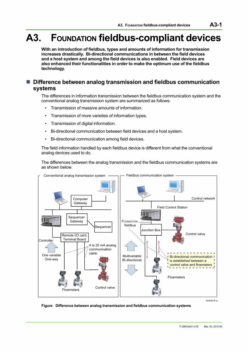
The differences in information transmission between the fieldbus communication system and the conventional analog transmission system are summarized as follows:
• Transmission of massive amounts of information.
• Transmission of more varieties of information types.
• Transmission of digital information.
• Bi-directional communication between field devices and a host system.
• Bi-directional communication among field devices.
The field information handled by each fieldbus device is different from what the conventional analog devices used to do.
The differences between the analog transmission and the fieldbus communication systems are as shown below.
A030001E.ai
Conventional analog transmission system Fieldbus communication system
ComputerGateway
SequencerGateway
SequencerFOUNDATION
fieldbusJunction Box
Field Control Station
Control network
Control valve
MultivariableBi-directional
Bi-directional communicationis established between a control valve and flowmeters
Flowmeters
One variableOne-way
4 to 20 mA analogcommunication cable
ControllerRemote I/O card,Terminal Board
Control valveFlowmeters
Figure Difference between analog transmission and fieldbus communication systems
Mar. 30, 2012-00
A3. FOUNDATION fieldbus-compliant devices A3-2
TI 38K03A01-01E
Enhancements in field devicesMore field devices with enhanced functionality have been developed in the past 10 years for the optimum use of fieldbus communication system.
For example, condition-based monitoring control and predictive maintenance of the field devices are enabled by transmitting self-diagnostic information periodically from the field devices to the host system. By exchanging PV, MV, and other data among field devices, autonomous distributed control of the multiple field devices are enabled.
When the process control system switched its main power source from pneumatic to electric, a lot of new electric field devices were released into the market. Similarly, along with the transition of communication system from the conventional analog transmission to the fieldbus, introduction of more fieldbus-compliant devices are expected.
Field devices are generally categorized into two groups: transmitters and actuators. And the fieldbus has brought about changes in both categories. All these changes are described in details in the following sections.
Mar. 30, 2012-00
A3. FOUNDATION fieldbus-compliant devices A3-3
TI 38K03A01-01E
A3.1 Changes in transmittersThe fieldbus communication system can transmit digital information via a single cable. And functional requirements of a transmitter have also been changed.
In a conventional analog transmission system, a transmitter is designed primarily to transmit process value (PV) to a production control system. This is because he analog transmission system performs one-way communication, from a field device to a production control system, or vice versa.
By using the fieldbus communication system, the amounts of information to be transmitted via a single cable increase drastically than that of a conventional analog transmission system. Bi-directional communications between the field devices and a production control system and among the field devices are established. Since the field devices transmits its digital information without converting, the information reliability also increases.
Mar. 30, 2012-00
A3. FOUNDATION fieldbus-compliant devices A3-4
TI 38K03A01-01E
A3.1.1 Accuracy improvement brought by digitalizationSince the fieldbus transmits information digitally, the field devices’ measuring data can be sent to the host system with minimum error.
Transmission accuracy improvementA transmitter with the conventional analog transmission displays its process value (PV) of the measuring range in percentage (relative value of 0 to 100 %), and convert and transmit this value to the host system in analog 4-to-20 mA DC signal. The host system converted this analog 4-to-20 mA DC signal back into the measured value before adopting it for processing. Errors are likely to occur during these signal conversions.
As for a transmitter with the fieldbus communication displays a PV as it is with engineering unit and transmits it digitally without conversion, to the host system. The host system uses the digital signal as it is transmitted. The data transmission via fieldbus does not require signal conversion, and the conversion errors of measured data during transmission can be eliminated.
The fieldbus communication provides higher data transmission accuracy compared to the analog transmission system.
Taking an example of flow measurement by using an orifice plate with a differential pressure transmitter, the difference in transmission accuracy between the analog transmission and fieldbus communication is as described below.
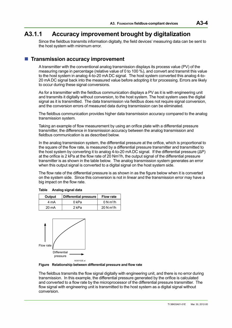
In the analog transmission system, the differential pressure at the orifice, which is proportional to the square of the flow rate, is measured by a differential pressure transmitter and transmitted to the host system by converting it to analog 4-to-20 mA DC signal. If the differential pressure (ΔP) at the orifice is 2 kPa at the flow rate of 20 Nm3/h, the output signal of the differential pressure transmitter is as shown in the table below. The analog transmission system generates an error when this output signal is converted to a digital signal on the host system side.
The flow rate of the differential pressure is as shown in as the figure below when it is converted on the system side. Since this conversion is not in linear and the transmission error may have a big impact on the flow rate.
Table Analog signal data
Output Differential pressure Flow rate 4 mA 0 kPa 0 N m3/h
20 mA 2 kPa 20 N m3/h
Differentialpressure
Flow rate
A030102E.ai
Figure Relationship between differential pressure and flow rate
The fieldbus transmits the flow signal digitally with engineering unit, and there is no error during transmission. In this example, the differential pressure generated by the orifice is calculated and converted to a flow rate by the microprocessor of the differential pressure transmitter. The flow signal with engineering unit is transmitted to the host system as a digital signal without conversion.
Mar. 30, 2012-00
A3. FOUNDATION fieldbus-compliant devices A3-5
TI 38K03A01-01E
Transmitter measuring accuracy improvementOnce the transmission accuracy is improved by the fieldbus communication, the transmitter’s measuring accuracy determines the overall accuracy of the production control system also improves.
Conventional mechanical flow meters and level meters are to be replaced by electronic flowmeters and level meters with digital technology.
The fieldbus communication transmits the measured data with engineering units, without converting regardless of the measuring range. A transmitter with a wide measuring range performs its full capacity in measurements. The wider measuring range of a transmitter may become a deterministic factor of its quality.
Mar. 30, 2012-00
A3. FOUNDATION fieldbus-compliant devices A3-6
TI 38K03A01-01E
A3.1.2 Multi-sensing functionWhen a transmitter measures several variables, it is called multi-sensing function.
In the fieldbus communication, multiple data can be transmitted via a single cable. To make the best use of this Fieldbus feature, multi-sensing transmitters have been developed.
In a conventional analog transmission, a cable per data is required for transmission of measured value. For example, a Coriolis flowmeter is capable of measuring multiple values and multiple cables are required to transmit all those data to the host system.
The fieldbus enables the Coriolis flowmeter to transmit multiple PVs via a single cable.
A lot of field devices with multi-sensing function have been developed along with the introduction of fieldbus.
For example, a differential pressure transmitter measures not only flow rates but also process pressure and ambient temperature. By combining functions of a temperature sensor for measuring the process temperature with this differential pressure transmitter, all the variables essential for process control such as flow rate, pressure, and temperature can be measured by a single device.
Here are the variables that a multi-sensing devices are capable of measuring.
Differential pressure flowmeter :Mass flow, volume flow, pressure, temperature
Magnetic flowmeter :Volume flow, conductivity, temperature
Vortex flowmeter :Mass flow, volume flow, temperature, pressure
Coriolis flowmeter :Mass flow, volume flow, density, temperature
Differential pressure level meter :Liquid level, density and specific gravity, tank internal pressure, temperature
Ultrasonic level meter :Liquid level, temperature
Temperature transmitter :Humidity, ambient temperature, vibration
pH meter :pH, temperature
Conductivity meter :Conductivity, temperature
Mar. 30, 2012-00
A3. FOUNDATION fieldbus-compliant devices A3-7
TI 38K03A01-01E
A3.1.3 Multiple function sensorsInformation other than PV can also be transmitted via fieldbus. To make the best use of this feature, a transmitter is equipped with a function to calculate and process multiple data necessary for process control. Such function of the transmitter is called “multiple function.”
The main function of a conventional analog transmitter is to measure PV at high accuracy and transmit it to the host system. A peripheral device is needed for converting the PV into the format appropriate for control.
With a multiple function transmitter, PVs are calculated and transmitted to the production control system in the format suitable for process control with engineering unit.
When the multiple function transmitter is used in combination with the aforesaid multi-sensing function, it drastically simplifies the production control system engineering.
Suppose there is a differential pressure transmitter capable of sensing flow rate, pressure, and temperature. When this transmitter is equipped with a computation function, it calculates the mass flow rate with temperature-pressure compensation based on the measured flow rate, pressure, and temperature before transmitting to the control system.
In the conventional analog transmission three devices for measuring flow rate, pressure, and temperature respectively, and an calculation unit for temperature-pressure compensation are required. A single multiple function, multiple sensing transmitter does it all in one device.
It drastically reduces the instrumentation cost and reliability degradation caused by using multiple instruments as well.
Mar. 30, 2012-00
A3. FOUNDATION fieldbus-compliant devices A3-8
TI 38K03A01-01E
A3.2 ActuatorActuators are benefited most by adopting fieldbus.This section explains. The benefits of adopting fieldbus using an example of control valve, a typical model for an actuator.
Innovations in control valve The progress in fieldbus communication technology brought drastic changes in the way of using control valves.
A control valve for a conventional analog transmission adjusted the valve positions by using a positioner referring to the manipulated value (MV) transmitted from the control system.
On the other hand, a control valve for fieldbus communication controls not only maintain the valve position but also returns the valve position data that complies with the MV back to the host system as well as to outputs limit signals to the host system. It enables to stabilize the process control without setting a valve positioner or limit switches separately.
Furthermore, these control valve and positioner for fieldbus performs modifications in characteristic and temperature compensations which have been traditionally done by the control system. It means that the control valve operation is done by monitoring the dynamic characteristics by reflecting the process status at best.
By integrating a positioner, a control valve, and a flowmeter in one device, the feedback control of the control valve, which is currently performed by the control system, can be concluded by the control valve alone.
Mar. 30, 2012-00
A3. FOUNDATION fieldbus-compliant devices A3-9
TI 38K03A01-01E
Features of fieldbus-compliant control valves• Control valve controllability is improved.
• Remote monitoring of control valve is enabled (by detecting stroke cycle and open-close time to predict clogging, sticking, leakage, and so on).
• Control valve characteristics are modified or improved.
• Control valve performance is stabilized by establishing the controllability and shutoff.
• Control valve stability is improved.
• Adjustment is made easy and control valve characteristics are stabilized.
• Control valve accessories are eliminated.
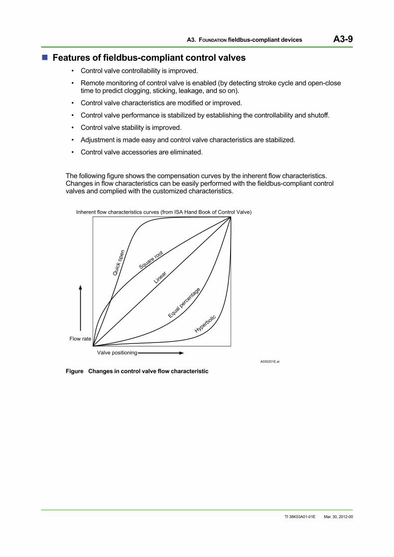
The following figure shows the compensation curves by the inherent flow characteristics. Changes in flow characteristics can be easily performed with the fieldbus-compliant control valves and complied with the customized characteristics.
Flow rate
Valve positioningA030201E.ai
Inherent flow characteristics curves (from ISA Hand Book of Control Valve)
Qui
ck o
pen
Square root
Equal
perce
ntage
Linea
r
Hyperbolic
Figure Changes in control valve flow characteristic
Mar. 30, 2012-00
A3. FOUNDATION fieldbus-compliant devices A3-10
TI 38K03A01-01E
A3.3 Using self-diagnostics functionIn the fieldbus communication field device failures can be predicted by using the self-diagnostics function.
Integration of instrumentation and self-diagnostics functionsThe conventional analog transmission handles only one signal per cable. PV or MV and self-diagnostics information are treated independently even those are from the same field device.
The fieldbus communication handles multiple signals on a single cable and PV or MV and self-diagnostics information are treated under the same condition. All the field works are integrated in a single network and the instrumentation and self-diagnostics are managed under the same environment, which is a new way of thinking the configuration.
Failure prediction functionIn the fieldbus communication, measured values are shown as read with engineering unit, which means that the slight changes in pressure and temperature other than PV can be detected with high accuracy. Fieldbus communication handles wider varieties of data. This enables the system to detect the symptoms of failures which have been not predictable.
Think of a situation that the field device’s self-diagnostics result cannot be judged as normal or abnormal. The conventional analog transmission system is only capable of sending the diagnostics result as either abnormal or normal. In such case, the host system always treats this kind of failures as abnormal, to be on the safe side of the operation. Even if the failure of the field device is a subtle one, alarms keep buzzing in the control room. However, if those minor failures of the field devices are handled as normal, alarms in the control room are drastically reduced and the symptom of more serious failures, if any, can be detected easily.
In the fieldbus communication when the self-diagnostics result cannot be judged as normal or abnormal, the device status and information can be sent to the host system. For instance, the information such as clogging and vibration which influences the measurement and control can be monitored. Through these functions, the host system is able to predict field device failures by analyzing the changes in the device status chronologically.
By using a dedicated package software, the maintenance work is made easier.
Mar. 30, 2012-00
A4. Yokogawa’s fieldbus-ready host systems A4-1
TI 38K03A01-01E
A4. Yokogawa’s fieldbus-ready host systems
A production control system, or host system, with fieldbus communication function deals with more advanced information than the control system with the conventional analog transmission. The key elements of the host system’s functions are to receive and display information, and manage historical records along with the advancement of information. This section describes how Yokogawa’s production control system supports fieldbus communication.
A4.1 CENTUM supports fieldbusCENTUM VP/CENTUM CS 3000 Integrated Production Control Systems support fieldbus communication.
The CENTUM VP/CENTUM CS 3000 systems are connected to field devices via I/O modules for 1-5 V DC, 4-20 mA, thermocouple, and resistance temperature detector, and digital inputs/outputs, and communication. The fieldbus communication module is considered as one of the I/O modules and can be used with other I/O modules for 4 - 20 mA analog transmission.
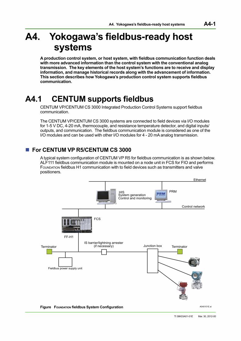
For CENTUM VP R5/CENTUM CS 3000A typical system configuration of CENTUM VP R5 for fieldbus communication is as shown below. ALF111 fieldbus communication module is mounted on a node unit in FCS for FIO and performs FOUNDATION fieldbus H1 communication with to field devices such as transmitters and valve positioners.
A040101E.ai
Control network
Terminator Terminator
Fieldbus power supply unit
IS barrier/lightning arrester (if necessary)
FF-H1
Ethernet
FCS
PRMHISSystem generationControl and monitoring
Junction box
Figure FOUNDATION fieldbus System Configuration
Mar. 30, 2012-00
A4. Yokogawa’s fieldbus-ready host systems A4-2
TI 38K03A01-01E
A4.2 Connecting third-party devices with CENTUM systems
Third-party FOUNDATION fieldbus-compliant field devices can be connected to CENTUM systems under the following conditions:
Devices must be registered to the Fieldbus FoundationThe Fieldbus Foundation prescribes the Interoperability Test (IT) procedures to ensure the field devices are interoperable. Those field devices which passed the IT are registered to the Foundation, and the information about those devices is published at the Fieldbus Foundation’s website (http://www.fieldbus.org/).The third-party field devices registered to the Fieldbus Foundation can be connected to CENTUM systems. Yokogawa recommends to use the devices registered with IT4.0 (or later version) along with the capabilities file and Device Description (DD) file. As for fieldbus accessories (e.g. cables, external bus power supply units, barriers, and arresters) which are out of scope of registration to the Fieldbus Foundation; use them in accordance with the specifications and conditions provided by the vendors. Yokogawa provides a list of fieldbus accessories under the selected equipment list. Contact Yokogawa for more information.
Devices must be used as instructedThird-party devices must be used under the conditions provided by their respective vendors for the quality, performance, and warranty of the field devices.
Devices tests must be performed by the user’s responsibilityA user is responsible for testing the third-party field devices to be used. Yokogawa, if required, provides a reference information on connecting third-party devices to CENTUM systems, for assisting users in device selection.
Yokogawa supports only fieldbus standard specifications, not vendor-specific optionsYokogawa’s host systems support information and functions that the Fieldbus Foundation defined as the standard specifications. Not all of the original functions of each vendor are supported by Yokogawa.The international standardization of the fieldbus specifications enabled operation and maintenance of field devices despite of the differences in vendors or device types. Yokogawa offers plant-wide start-up and maintenance of production control system including third-party instruments, which is to serve our customers in better ways to establish VigilanPlant, an ideal plant.
Mar. 30, 2012-00
TocB-1
TI 38K03A01-01E
Fieldbus Technical InformationPart B Fieldbus Engineering
CONTENTS
TI 38K03A01-01E 4th Edition
Mar. 30, 2012-00
B1. Managing fieldbus engineering ............................................................B1-1B1.1 Fieldbus engineering overview .................................................................... B1-1B1.2 Differences in process control system
using fieldbus and analog signal ................................................................ B1-4B1.3 Software packages for fieldbus ................................................................... B1-5
B2. System Design Considerations ............................................................B2-1B2.1 Key points in basic and overall designs ..................................................... B2-2B2.2 Key points in detail design ........................................................................... B2-3
B2.2.1 Number of field devices connected to an H1 segment ....................B2-4
B2.2.2 Fieldbus cable and wiring selections ...............................................B2-5
B2.2.3 Designing fieldbus device grouping per segment ...........................B2-7
B2.2.4 Expansion and modification of the existing system .........................B2-7
B3. Installation guidance ..............................................................................B3-1B3.1 New installation of a production control system
with fieldbus communication ....................................................................... B3-1B3.1.1 Mounting Terminators ......................................................................B3-3
B3.1.2 Cabling .............................................................................................B3-3
B3.1.3 Installation of an intrinsically safe barrier .........................................B3-3
B3.1.4 Handling the shield mesh ................................................................B3-3
B3.2 Reusing of the existing cables ..................................................................... B3-4
B4. Starting up the system ...........................................................................B4-1B4.1 Start-up tools .................................................................................................. B4-1B4.2 Techniques and expertise required for system start-up ........................... B4-2B4.3 Saving a start-up labor .................................................................................. B4-3
B5. System maintenance .............................................................................B5-1B5.1 Daily Maintenance .......................................................................................... B5-1B5.2 Maintenance and Inspection ........................................................................ B5-2B5.3 Maintenance Management (Maintenance planning, asset management, and audit trail) .................... B5-3B5.4 Evolution in Maintenance ............................................................................. B5-3

Blank Page
B1. Managing fieldbus engineering B1-1
TI 38K03A01-01E
B1. Managing fieldbus engineeringIn a production control system with the fieldbus technology, the engineering procedures are different from that with the conventional analog signals. The engineering procedures of a production control system with the FOUNDATION fieldbus H1 (31.25 kbps) is described in this section.
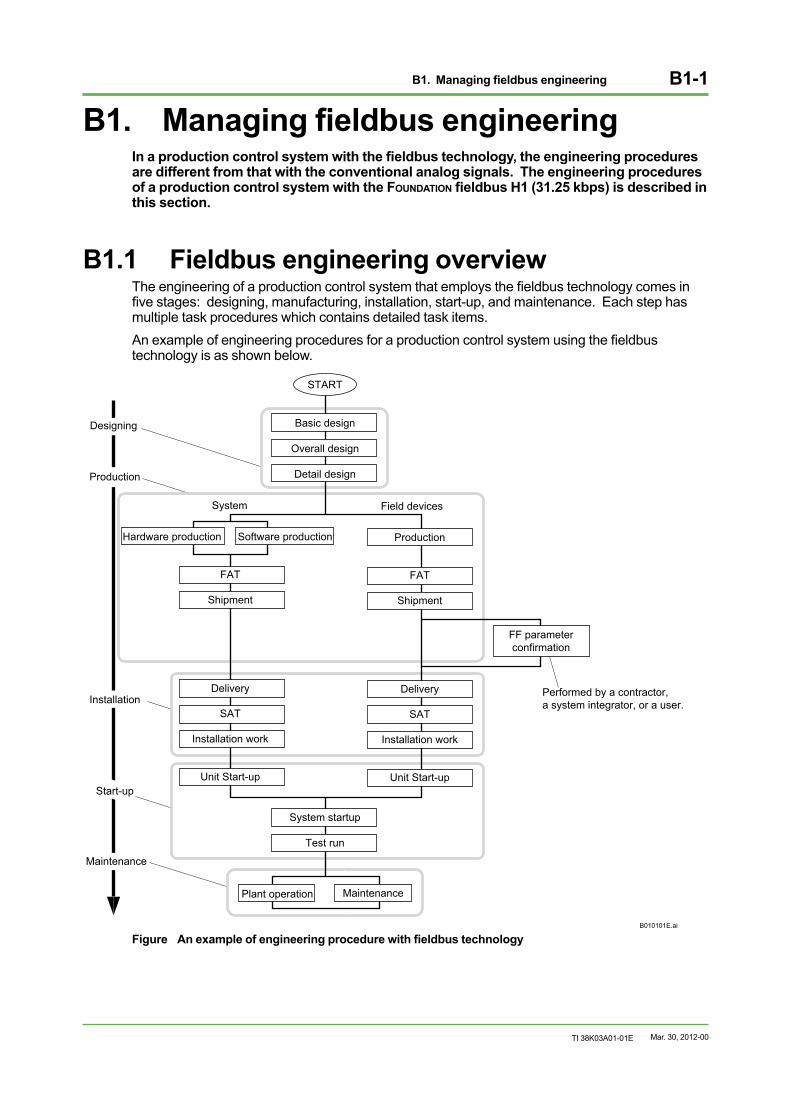
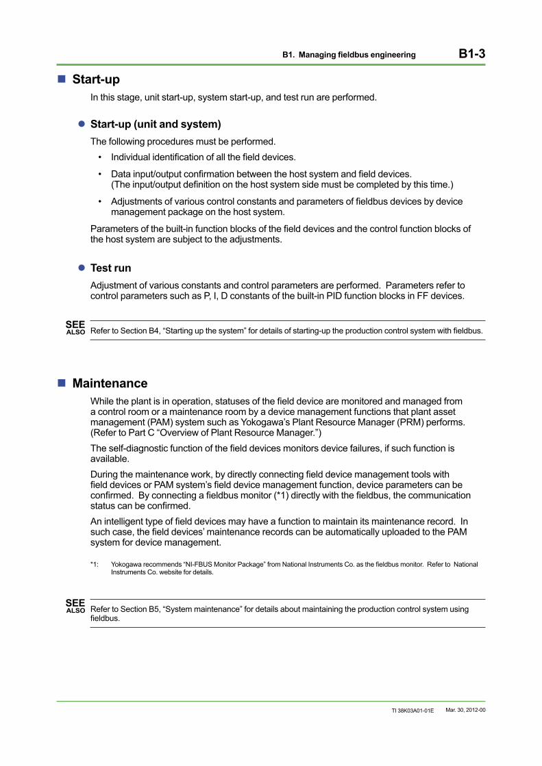
B1.1 Fieldbus engineering overviewThe engineering of a production control system that employs the fieldbus technology comes in five stages: designing, manufacturing, installation, start-up, and maintenance. Each step has multiple task procedures which contains detailed task items.An example of engineering procedures for a production control system using the fieldbus technology is as shown below.
START
Basic design
Overall design
Detail design
Hardware production
FAT
Shipment
Delivery
SAT
Installation work
Unit Start-up
Production
FAT
Shipment
Delivery
SAT
Installation work
Unit Start-up
FF parameterconfirmation
System startup
Test run
Plant operation
System Field devices
Start-up
Designing
Production
Installation
Maintenance
Performed by a contractor, a system integrator, or a user.
Maintenance
Software production
B010101E.ai
Figure An example of engineering procedure with fieldbus technology
Mar. 30, 2012-00
B1. Managing fieldbus engineering B1-2
TI 38K03A01-01E
DesigningA detailed design of the production control system is clarified through basic design, overall design, and detail design stages.
SEE ALSO Refer to Section B2, “System Design Considerations” for detailed information about designing the production
control system using fieldbus.
ManufacturingAccording to the specifications that are confirmed in the designing stage, a production control system and field devices are produced. The manufacturing and assembling are solely performed by Yokogawa, and no work done by the user.
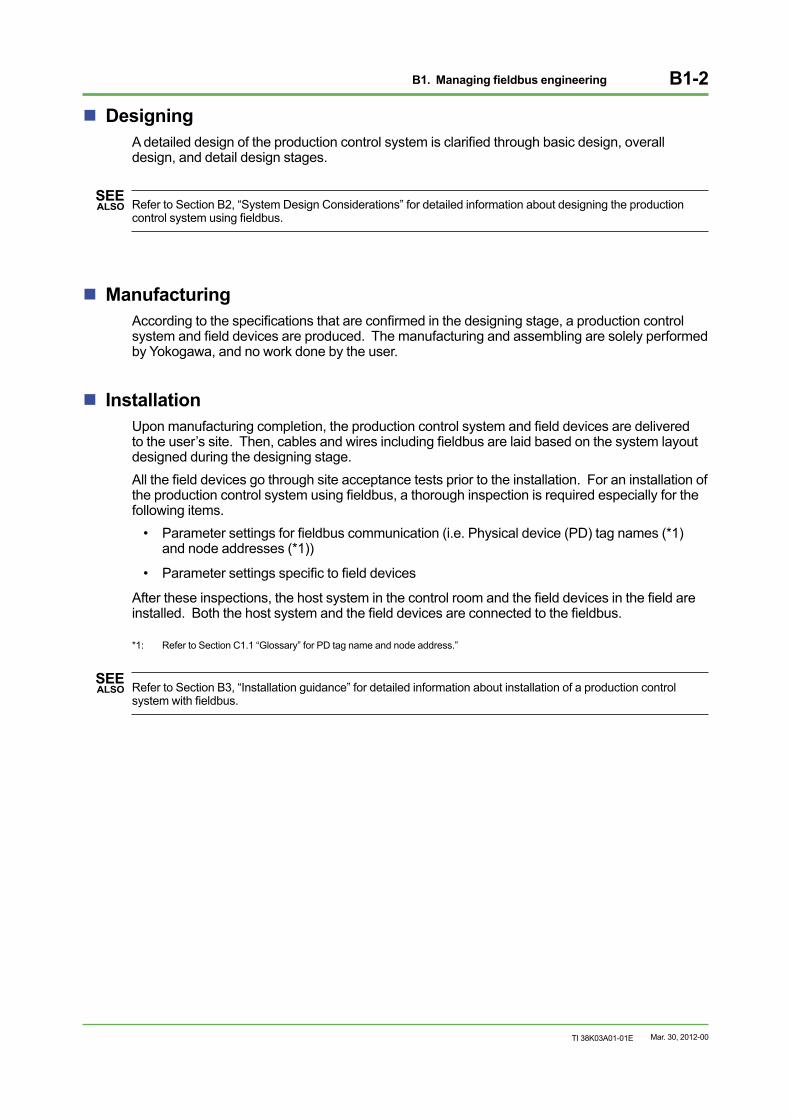
InstallationUpon manufacturing completion, the production control system and field devices are delivered to the user’s site. Then, cables and wires including fieldbus are laid based on the system layout designed during the designing stage.All the field devices go through site acceptance tests prior to the installation. For an installation of the production control system using fieldbus, a thorough inspection is required especially for the following items.
• Parameter settings for fieldbus communication (i.e. Physical device (PD) tag names (*1) and node addresses (*1))
• Parameter settings specific to field devices
After these inspections, the host system in the control room and the field devices in the field are installed. Both the host system and the field devices are connected to the fieldbus.
*1: Refer to Section C1.1 “Glossary” for PD tag name and node address.”
SEE ALSO Refer to Section B3, “Installation guidance” for detailed information about installation of a production control
system with fieldbus.
Mar. 30, 2012-00
B1. Managing fieldbus engineering B1-3
TI 38K03A01-01E
Start-upIn this stage, unit start-up, system start-up, and test run are performed.
Start-up (unit and system)The following procedures must be performed.
• Individual identification of all the field devices.
• Data input/output confirmation between the host system and field devices. (The input/output definition on the host system side must be completed by this time.)
• Adjustments of various control constants and parameters of fieldbus devices by device management package on the host system.
Parameters of the built-in function blocks of the field devices and the control function blocks of the host system are subject to the adjustments.
Test runAdjustment of various constants and control parameters are performed. Parameters refer to control parameters such as P, I, D constants of the built-in PID function blocks in FF devices.
SEE ALSO Refer to Section B4, “Starting up the system” for details of starting-up the production control system with fieldbus.
MaintenanceWhile the plant is in operation, statuses of the field device are monitored and managed from a control room or a maintenance room by a device management functions that plant asset management (PAM) system such as Yokogawa’s Plant Resource Manager (PRM) performs. (Refer to Part C “Overview of Plant Resource Manager.”)The self-diagnostic function of the field devices monitors device failures, if such function is available. During the maintenance work, by directly connecting field device management tools with field devices or PAM system’s field device management function, device parameters can be confirmed. By connecting a fieldbus monitor (*1) directly with the fieldbus, the communication status can be confirmed.An intelligent type of field devices may have a function to maintain its maintenance record. In such case, the field devices’ maintenance records can be automatically uploaded to the PAM system for device management.
*1: Yokogawa recommends “NI-FBUS Monitor Package” from National Instruments Co. as the fieldbus monitor. Refer to National Instruments Co. website for details.
SEE ALSO Refer to Section B5, “System maintenance” for details about maintaining the production control system using
fieldbus.
Mar. 30, 2012-00
B1. Managing fieldbus engineering B1-4
TI 38K03A01-01E
B1.2 Differences in process control system using fieldbus and analog signal
Production control systems with a conventional analog signals differ greatly from the one with fieldbus which additionally require parameters for fieldbus configuration definitions to be set.
Field-device-specific parameter settingA work procedure to set various FOUNDATION fieldbus function block parameters for field devices. Followings are some of the main parameters in the FOUNDATION fieldbus function block:
• Range parameters (XD_scale, OUT_scale, and engineering unit for each scale)
• Compensation parameters (Direct, indirect, indirect Sqr Root)
• Input filter process parameters (PV_FTIME)
Parameters setting for fieldbus communication and its functionsA function to set parameters related to fieldbus communication and fieldbus-related functions.Representing parameters are as shown below:
• PD tag name (*1)
• Node address (*1)
• FOUNDATION fieldbus function block definition
• Link information (i.e. connecting blocks, output parameters, etc.)
*1: Refer to Section C1.1 “Glossary” for PD tag name and node address.
Mar. 30, 2012-00
B1. Managing fieldbus engineering B1-5
TI 38K03A01-01E
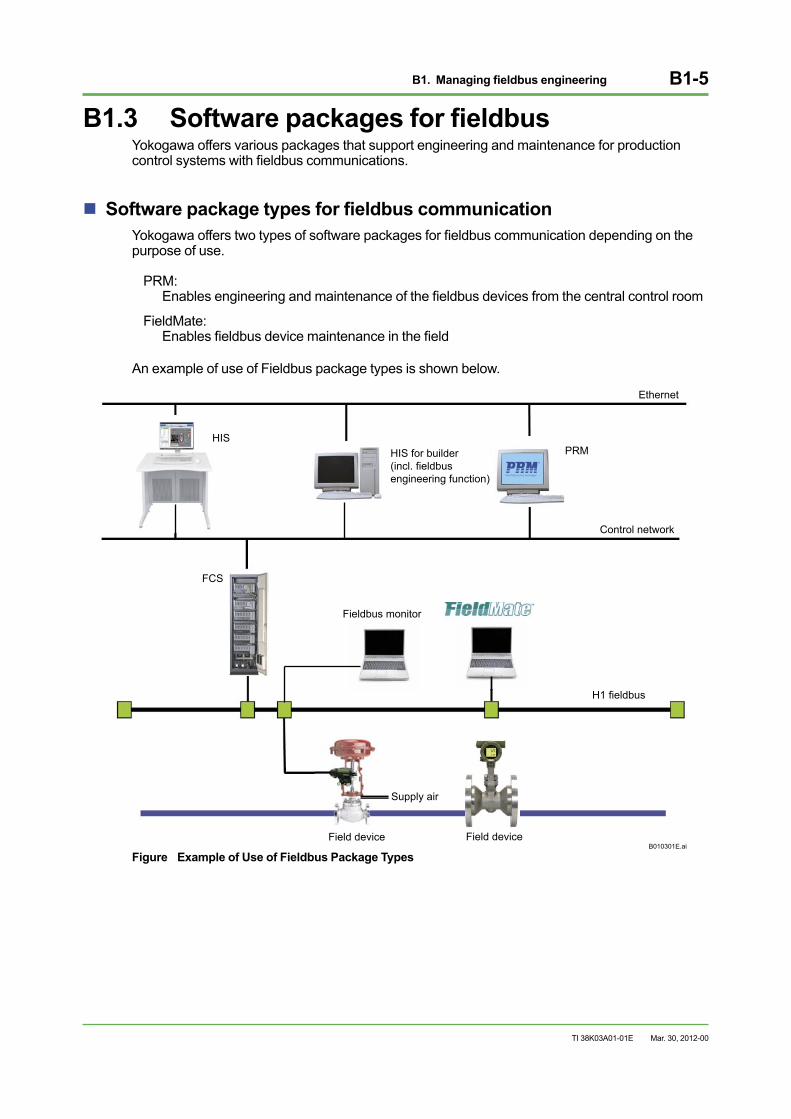
B1.3 Software packages for fieldbusYokogawa offers various packages that support engineering and maintenance for production control systems with fieldbus communications.
Software package types for fieldbus communicationYokogawa offers two types of software packages for fieldbus communication depending on the purpose of use.
PRM: Enables engineering and maintenance of the fieldbus devices from the central control room
FieldMate: Enables fieldbus device maintenance in the field
An example of use of Fieldbus package types is shown below.
B010301E.ai
Fieldbus monitor
Field device Field device
Ethernet
H1 fieldbus
Supply air
HIS for builder (incl. fieldbus engineering function)
FCS
Control network
HISPRM
Figure Example of Use of Fieldbus Package Types
Mar. 30, 2012-00
B1. Managing fieldbus engineering B1-6
TI 38K03A01-01E Mar. 30, 2012-00
Fieldbus engineering and device maintenance in the central control roomThis package is designed for fieldbus engineering and field device maintenance performed in the central control room.
• Fieldbus engineering is performed in association with a host system On top of the conventional system builder function, device registration to the fieldbus segments and FOUNDATION fieldbus block linkage are performed. Remote parameter setting (adjustment) and remote diagnosis of field devices are performed by the device management tool (DMT) or PRM.
• Parameter setting (adjustment) and diagnosis of the field devices Remote parameter setting and remote diagnosis of field devices are performed by the DMT or PRM.
Field device maintenance in the fieldBy connecting the FieldMate with the fieldbus directly, fieldbus devices’ status monitoring is enabled. Parameter setting of the field devices and operation check prior to the actual plant operation.
B2. System Design Considerations B2-1
TI 38K03A01-01E
B2. System Design ConsiderationsWhen designing a production control system with fieldbus communication protocol, sufficient knowledge on fieldbus engineering is mandatory. Key points in designing production control system with fieldbus communication are described in this section.
Importance of production control system designThe production control system design procedure must follow these steps:
• Basic design
• Overall design for common specifications
• Detail design for individual components
The basic and overall designs are done at first. In case the basic and overall designs are not clearly specified, inconsistencies or discrepancies of the specifications may occur during the individual design stage that cause reworks. The more the production control system becomes complicated, the more the basic and overall designs become important.During the detail design, the individual components are materialized based on the basic and overall designs.
Designing a production control systems with fieldbusIn designing a production control system with fieldbus communication, greater number of elements need to be considered than that with conventional analog transmissions.It does not mean that designing a process control systems with fieldbus communication is more complicated. It can start with the traditional engineering methods of designing based on the production control system with conventional analog transmissions, and add up fieldbus-related elements to it.
Mar. 30, 2012-00
B2. System Design Considerations B2-2
TI 38K03A01-01E
B2.1 Key points in basic and overall designsDuring the basic design of a production control system with fieldbus communication, it is necessary to properly consider the purpose of introducing the production control system and its installation costs. While doing the overall design, the system configuration and the scope of integration or grouping of the production control system must be carefully considered.
For basic designFollowing elements must be considered.
• Purpose of introducing a production control system
• System configuration costs (including overall installation cost)
• Delivery schedule for system configuration
• Safety policy
• Operation and monitoring
• Maintenance
For overall designFollowing elements, including common specifications among all the production control system and equipment, must be considered.
• Configuration of the production control system (both hardware and software)
• Scope and level of Integration and grouping
• System safety design and reliability improvement
• Countermeasure in case of abnormal conditions
• Interface design
• Future expansion and modifications
Mar. 30, 2012-00
B2. System Design Considerations B2-3
TI 38K03A01-01E
B2.2 Key points in detail designDuring the detail design stage, the contents of the basic design and overall design are materialized. In this section, major elements in designing individual components are described. Considerations for limitations and restrictions such as cable length, power supply capacity and so on are also important.
Scope and level of integration and grouping• Integration of control network between the production control system and other systems
• Consistency in operation styles between the production control system and other systems
• System integration through upper- and lower-level communications
• Number of connecting field devices and its grouping
• Clarifications of hardware/software configurations referring to the system configuration drawings
System safety design and reliability improvement• Device selection devices and installation in hazardous area (how to supply power to
intrinsically safe devices)
• Assignments for system functionality of I/O for fieldbus and conventional analog devices. For instance, an emergency shutdown system shall be designed using a control system with conventional analog signals.
• Selection in cable types and field devices. Providing dual-redundant configuration for FOUNDATION fieldbus power supply unit and fieldbus interface module.
• Fail-safe design, safety policy by establishing the diagnostics functions and designs
• Selections of noise resistant devices and wiring route to minimize noise (influenced by high voltage or motors)
• Selection of fieldbus accessories such as FOUNDATION fieldbus power supply units, terminators, intrinsically safe barriers and arresters.
• Designing a link master (LM) device with link active scheduler (LAS) function and a backup LM device with LAS function.
Mar. 30, 2012-00

B2. System Design Considerations B2-4
TI 38K03A01-01E
B2.2.1 Number of field devices connected to an H1 segmentThe number of field devices to be connected to an H1 segment is determined by the power supply’s electric current capacity, a macrocycle corresponding to the scan period, and fieldbus cable lengths. For the restriction in fieldbus cable length, refer to Section B2.2.2, “Fieldbus cable and wiring selections.”
By power supply capacityThe number of devices to be connected to a field bus segment is determined by the total sum of the electric current consumption. As for intrinsically safe systems, the total sum of the electric current consumption must be kept within the limit of the intrinsically safe barriers.
By macrocycle corresponding to the control scan periodThe number of field devices to be connected to an H1 segment is determined by the macrocycle corresponding to the control scan period.A macrocycle is a control or measurement scan period of which unit is 1/32 ms (1 sec = 32000 units). The scheduled control scans and communications of macrocycle is executed by the LM device with LAS function.
Mar. 30, 2012-00
B2. System Design Considerations B2-5
TI 38K03A01-01E
B2.2.2 Fieldbus cable and wiring selectionsThe fieldbus cable specifications are the important in designing fieldbus systems. Considerations to voltage drop is required.Yokogawa has been investigated in fieldbus cable specifications on various aspects. Use the cable data described in this document for reference when selecting one. Yokogawa’s recommendation is a type A cable.
Consideration to voltage drop The voltage drop limit is a margin to secure the minimum operable voltage for devices even the voltage drop in the cable resistance is deducted from the minimum power supply voltage, considering the fluctuations. Yokogawa recommends 9.5 volts or higher as an operable voltage.
Cable types and its resistanceThe typical resistances per unit length of the various cable types that can be used for Fieldbus are shown below. The following resistance values are for reference only. For actual values, contact the cable manufacturer.Type A (individually shielded twisted-pair cable) : 22 ohm/kmType B (multi-pair cable, twisted, with outer shield) : 56 ohm/kmType D (multi-pair cable, no twist, with outer shield) : 20 ohm/km
Confirm if the minimum supply voltage is secured for each fieldbus device using the below computation formula.
Minimum power supply voltage = (Resistance per unit length cable length) device’s electric current consumption + Minimum operating voltage
Wiring cable selectionsElements of noises, costs, flexibility, and explosion-proof need to be considered.
Insulating material for twisted-pair cableThe insulating material such as polyethylene is appropriate.
Bus topology and number of devices per segmentBus topology (i.e. serial, tree, or single) and maximum number of devices per segment must be considered.
Mar. 30, 2012-00
B2. System Design Considerations B2-6
TI 38K03A01-01E
Cable types and total cable lengthWhen a twisted-pair cable is used for the main line, select the cable type and total cable length carefully knowing the following limitations.The total cable length for fieldbus is as follows.
Type A (Individually-shielded twisted pair cable) : 1900 m
Type B (multi-pair cable, twisted, with outer shield) : 1200 m
Type D (multi-pair cable, no twist, with outer shield) : 200 m
Some of the type B cables attenuate signals largely. In order to secure sufficient signal amplitude, connect less than 20 field devices for a total cable length of 600 m, or 10 field devices for 1200 m.When type D cables are applied, use only up to two pairs of cables for fieldbus, and each pair must be isolated to prevent interference. When multiconductor cables are used, transmit only fieldbus or analog (including hybrid communication) signals on the same cable, and do not mix them with others.
Number of branch cables and cable total lengthWhen the tree topology is applied, the total cable length must be carefully considered in accordance with the number of spur (branch) cables (which means the number of field devices to be connected). The standard value of the total length of spur cables are defined by IEC and ISA standards (*1) as follows.
For 1 to 12 field devices : 120 m
For 13 to 14 field devices : 90 m
For 15 to 18 field devices : 60 m
For 19 to 24 field devices : 30 m
For 25 to 32 field devices : 0 m
The number of connected field devices may be smaller due to the limitations deprived from power supplies, communication performance and other conditions.
In principle, the total lengths of the spur cables must be set within the standard value of the total cable lengths as shown above. However, in some applications these maximum lengths may exceed, thus more practical spur cable length setting is required. Knowing that the IEC and ISA standard cable lengths are recommended, Yokogawa figured out the possibility of extending these length when used with Yokogawa’s CENTUM production control systems.
Type A fieldbus cable is applied.
Number of field devices per segmen : Max. 16 devices (Yokogawa assumes this is a practical number.)
Length of a spur cable : 120 m or less
Total length of spur cables : 1440 m or less
Total length of a trunk cable : 1900 m (minus) total length of spur cable, or less
There is no limitation for number of junction boxes for connecting field devices to spur cables.
*1: The standard value of the total spur cable lengths are shown in the IEC61158-2 and ISA - S50.02 Annex C (informative).
Mar. 30, 2012-00
B2. System Design Considerations B2-7
TI 38K03A01-01E Mar. 30, 2012-00
B2.2.3 Designing fieldbus device grouping per segment• Communication and control performance must be considered for transmission speed,
control cycle, communication cycle, and number of communication parameters between field devices and a production control system.
• Types and amounts of information must be sorted out (essential, expected, or nice-to-have information).
• Future expansion must be considered (i.e. reservations of spare wiring space and addition of spare devices.)
B2.2.4 Expansion and modification of the existing system• The purpose and the level of expansion must be clarified, influences to the existing system
has to be investigated, and a beneficial production control system has to be configured.
• Feasibility study or a trial test for introducing of fieldbus has to be conducted.
• An interface with the existing devices (analog/digital conversion) needs to be designed.
• Usability of the existing wiring has to be investigated.
B3. Installation guidance B3-1
TI 38K03A01-01E
B3. Installation guidanceWhen designing a production control system with fieldbus communication, a thorough understanding of the fieldbus-related installation methods is necessary. This section describes an installation guidance for a production control system fieldbus communication.
B3.1 New installation of a production control system with fieldbus communication
For wiring of a production control system with fieldbus communication in a new installation, typical system wiring configurations of “serial link type” and “tree type” are explained as below.
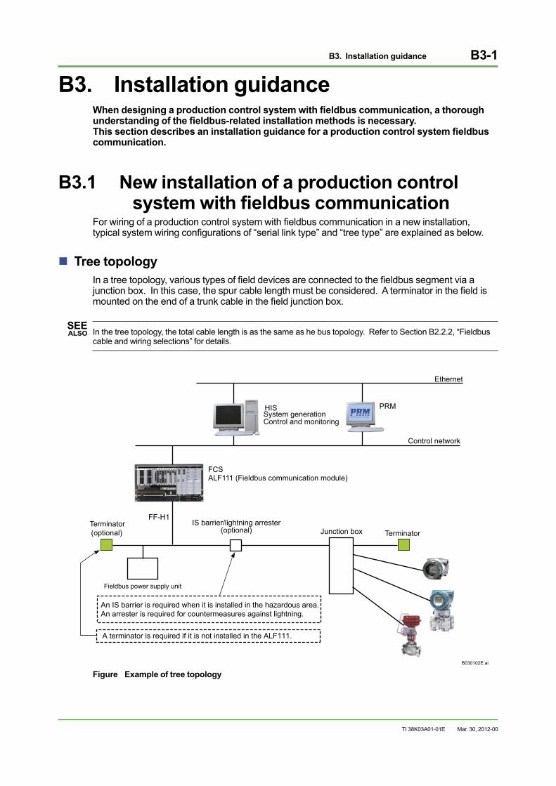
Tree topologyIn a tree topology, various types of field devices are connected to the fieldbus segment via a junction box. In this case, the spur cable length must be considered. A terminator in the field is mounted on the end of a trunk cable in the field junction box.
SEE ALSO In the tree topology, the total cable length is as the same as he bus topology. Refer to Section B2.2.2, “Fieldbus
cable and wiring selections” for details.
B030102E.ai
Terminator(optional)
Fieldbus power supply unit
IS barrier/lightning arrester (optional)
A terminator is required if it is not installed in the ALF111.
An IS barrier is required when it is installed in the hazardous area.An arrester is required for countermeasures against lightning.
ALF111 (Fieldbus communication module)
Control network
Terminator
FF-H1
Ethernet
FCS
PRMHISSystem generationControl and monitoring
Junction box
Figure Example of tree topology
Mar. 30, 2012-00
B3. Installation guidance B3-2
TI 38K03A01-01E
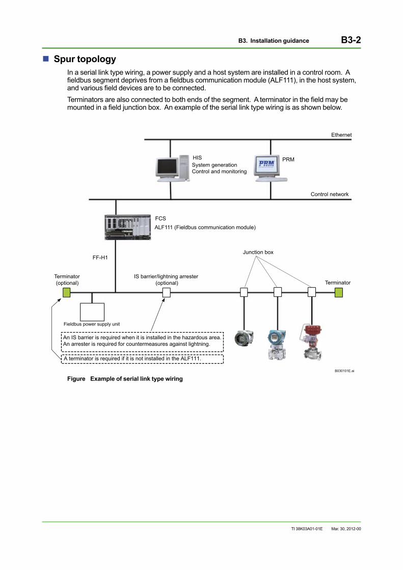
Spur topologyIn a serial link type wiring, a power supply and a host system are installed in a control room. A fieldbus segment deprives from a fieldbus communication module (ALF111), in the host system, and various field devices are to be connected.Terminators are also connected to both ends of the segment. A terminator in the field may be mounted in a field junction box. An example of the serial link type wiring is as shown below.
B030101E.ai
FCS
Control network
HIS
Terminator Terminator(optional)
Fieldbus power supply unit
IS barrier/lightning arrester (optional)
Junction boxFF-H1
Ethernet
PRMSystem generationControl and monitoring
ALF111 (Fieldbus communication module)
A terminator is required if it is not installed in the ALF111.
An IS barrier is required when it is installed in the hazardous area.An arrester is required for countermeasures against lightning.
Figure Example of serial link type wiring
Mar. 30, 2012-00
B3. Installation guidance B3-3
TI 38K03A01-01E
B3.1.1 Mounting TerminatorsTerminators must always be mounted on both ends of a trunk cable. Various types of terminators such as a field device built-in type and a stand-alone type are available in the market from various manufacturers.
B3.1.2 CablingStandard conduits are used for protection of the fieldbus cables. In case the fieldbus cable is stored in the cable rack or wiring duct, segregate those cables from other cables as much as possible, as in the same manners as when installing low-level signal cables.33Q01J10-01E).”
B3.1.3 Installation of an intrinsically safe barrierIn case an intrinsically safe application is required, intrinsically safe barriers are to be installed in a rack room nearest to the field. The cables in the hazardous and the non-hazardous areas must be wired separately.Note that the intrinsically safe barriers attenuate signals.
B3.1.4 Handling the shield meshIn case a shielded cable is used, the following points in handling the shield mesh must be considered.
• Connecting shield mesh at the coupler
• Locations and numbers of grounding
Basically, the shielded fieldbus cable must apply one-point grounding inside the control room building.
Mar. 30, 2012-00
B3. Installation guidance B3-4
TI 38K03A01-01E
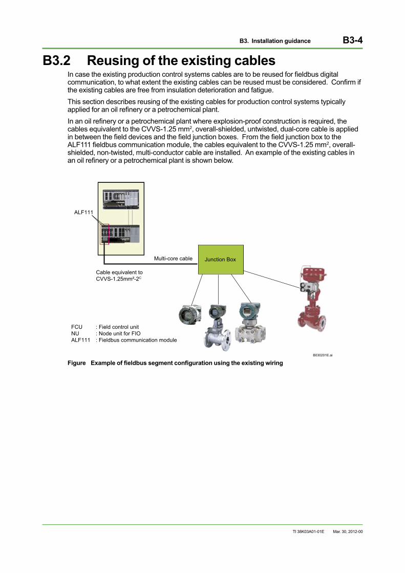
B3.2 Reusing of the existing cablesIn case the existing production control systems cables are to be reused for fieldbus digital communication, to what extent the existing cables can be reused must be considered. Confirm if the existing cables are free from insulation deterioration and fatigue.This section describes reusing of the existing cables for production control systems typically applied for an oil refinery or a petrochemical plant.In an oil refinery or a petrochemical plant where explosion-proof construction is required, the cables equivalent to the CVVS-1.25 mm2, overall-shielded, untwisted, dual-core cable is applied in between the field devices and the field junction boxes. From the field junction box to the ALF111 fieldbus communication module, the cables equivalent to the CVVS-1.25 mm2, overall-shielded, non-twisted, multi-conductor cable are installed. An example of the existing cables in an oil refinery or a petrochemical plant is shown below.
B030201E.ai
FCU : Field control unitNU : Node unit for FIOALF111 : Fieldbus communication module
Cable equivalent toCVVS-1.25mm²-2C
Multi-core cable Junction Box
ALF111
Figure Example of fieldbus segment configuration using the existing wiring
Mar. 30, 2012-00
B3. Installation guidance B3-5
TI 38K03A01-01E
Reusing the cables between field devices and junction boxMost of the existing cables (spur cables) in between the field devices and the field junction box use the CVVS-1.25 mm², overall-shielded, non-twisted dual-core cable. In this case the maximum cable length depends on the type of cable and the number of connected field devices.The following tables show the cable types, specifications, and the maximum length of spur (branch) cables according to the number of devices on the fieldbus.
Table Cable Types (Reference value)
Types of cables Cable size Max. length of cable Type A: Individually shielded twisted-pair cable 0.82 mm2 1900 m Type B: Multi-pair cable, twisted, with outer shield 0.32 mm2 1200 m Type D: Multi-pair cable, no twist, with outer shield 1.25 mm2 200 m
Table Maximum length of spur cables (Reference value)
Number of devices on fieldbus Max. length of spur cables 1 to 12 120 m 13 to 14 90 m 15 to 18 60 m 19 to 24 30 m 25 to 32 0 m
SEE ALSO Refer to Section B2.2.2, “Fieldbus cable and wiring selections” for cables types and topologies.
Reusing the cables in between the field junction box and the control room
Most of the existing cables (trunk cables), from the field junction box to the control room (relay terminal board), use the CVVS-1.25 mm², overall-shielded, non-twisted, multiconductor cable. Within the maximum cable length listed in the above table, cables shown in the “Types of Cables (Reference value)” can be reused.These cables can be used for fieldbus as the noise interference by the cross talk is usually within the permissible range.When different types of cables are connected, the maximum length of each cable becomes shorter than those shown in the “Types of Cables (Reference value).”
Mar. 30, 2012-00
B4. Starting up the system B4-1
TI 38K03A01-01E
B4. Starting up the systemBefore starting up a control system with fieldbus communication, a thorough understanding of all aspects concerning the system startup is needed. This section describes the tools and technologies required for starting up the fieldbus system, as well as the differences in the startup processes between the fieldbus system and the conventional analog system.
B4.1 Start-up toolsFor start-up of a fieldbus control system, tools are different from those of a conventional analog system are used. This section describes a variety of tools used for starting up the system.
Field device maintenance tool For starting up a fieldbus system, a field device maintenance tools such as FieldMate and PRM are required for parameter setting (especially for remote set up).
Digital signal measuring instrumentsDigital signal measuring instruments are used for starting up a production control system with fieldbus communication.These digital signal instruments, connected to field devices or fieldbus interface modules, measure digital signals. A digital multimeter, a digital oscilloscope, and Fieldbus testers (*1) from Relcom Inc. are used to measure network communication related items such as the current, volts, LAS status, number of connected devices, signal level, noise level, and so on.
*1: Yokogawa recommends “Fieldbus network testers (i.e. FBT-3)” from Relcom Inc. <http://www.relcominc.com/> as fieldbus testers.
Fieldbus monitorA fieldbus monitor (*1) may be useful for measuring signal data on the fieldbus for starting up a production control system with the fieldbus communication protocol for trouble shooting. The fieldbus monitor is equipped with a troubleshooting function which can track down the causes of communication failures among the devices connected to the segment.
*1: Yokogawa recommends “NI-FBUS Monitor Package” from National Instruments Co. <http://www.ni.com/> as a fieldbus monitor.
Mar. 30, 2012-00
B4. Starting up the system B4-2
TI 38K03A01-01E
B4.2 Techniques and expertise required for system start-up
For a starting up of a control system with fieldbus communication, different types of techniques and expertise from those of a control system with conventional analog communications are required. This section describes those techniques and expertise required.
Wiring techniqueWiring method is drastically changed by the introduction of the fieldbus. Minimization of wiring is one of the main advantages of the fieldbus communication. However, on the other hand, the terminator treatment of the communication cables require more attention than for the analog communication. Since a single fieldbus cable handles multiple signals, failures in wiring has influences to the control system. A careful inspection of the communication cables and if the wiring is done in accordance with the field devices’ specifications as well as communication transmission quality must be thoroughly performed.
Field devicesHandling of the field devices are easier because the sensor outputs are digitalized, even the measuring methods (principles) for pressure flow rate are the same as the conventional types of field devices.The remote maintenance is enabled by the field device maintenance tool, which saves labor in field device signal processing such as operation checks, device adjustment, changes in parameter setting, and data maintenance management.
System softwareStart-up engineers must have knowledge in communication such as various communication software set-up and communication protocols.
Application softwareThree control methods can be applied for control systems with fieldbus communication as shown below:
• Field devices perform all the control, and the host system only performs monitoring.
• All the control signals are transmitted to the host system which performs all the control.
• A combination of the above two methods which allows the optimized control for specific applications.
These control methods further distributed the controls than the conventional production control systems in which all the process control is performed. For instance, the host system is able to perform higher-level control (i. e. multivariable control or advanced control) by assigning simple controls to the field devices. And start-up engineers must have knowledge about advanced control as well.
Since the process control is further distributed and the role of the host system becomes more of the production management computer, the start-up engineers must have knowledge about information management system as well as the production control system.
Mar. 30, 2012-00
B4. Starting up the system B4-3
TI 38K03A01-01E
B4.3 Saving a start-up laborIn the start-up of a production control system with fieldbus communication, a part of the labor can be saved in some processes, compared to a conventional analog system. This section describes the processes where labor can be saved.
Loop Check
For a production control system with conventional analog signal communicationLoop checks are usually performed twice for the production control system with conventional analog communication – an indoor and an overall loop checks. The indoor loop check examines the wiring and signal quality of the loops from the marshalling rack to the production control system in the building. The overall loop check examines wiring and signal quality between field devices and the production control system. The indoor loop check makes the troubleshooting during the overall loop check easier. However, the loop checks requires a lot of man-hours to perform these things for all the loops.
Mar. 30, 2012-00
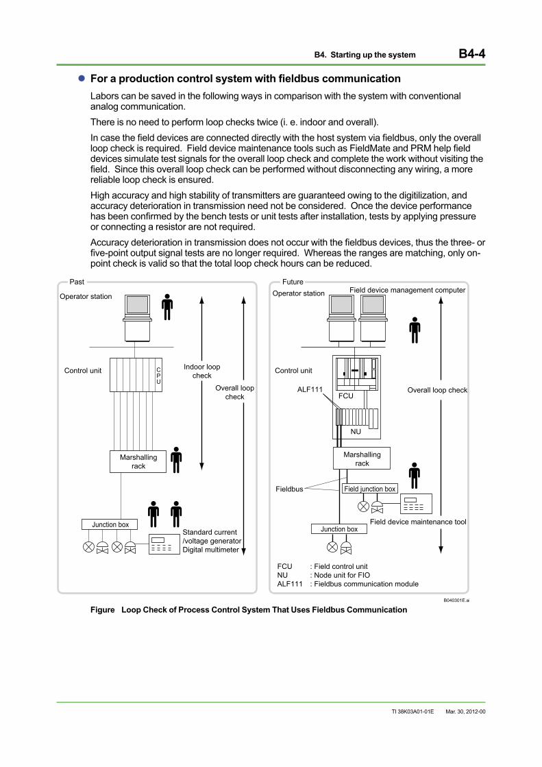
B4. Starting up the system B4-4
TI 38K03A01-01E
For a production control system with fieldbus communicationLabors can be saved in the following ways in comparison with the system with conventional analog communication.There is no need to perform loop checks twice (i. e. indoor and overall).In case the field devices are connected directly with the host system via fieldbus, only the overall loop check is required. Field device maintenance tools such as FieldMate and PRM help field devices simulate test signals for the overall loop check and complete the work without visiting the field. Since this overall loop check can be performed without disconnecting any wiring, a more reliable loop check is ensured.High accuracy and high stability of transmitters are guaranteed owing to the digitilization, and accuracy deterioration in transmission need not be considered. Once the device performance has been confirmed by the bench tests or unit tests after installation, tests by applying pressure or connecting a resistor are not required. Accuracy deterioration in transmission does not occur with the fieldbus devices, thus the three- or five-point output signal tests are no longer required. Whereas the ranges are matching, only on-point check is valid so that the total loop check hours can be reduced.
B040301E.ai
Operator station
Control unit Control unit
Standard current/voltage generatorDigital multimeter
Indoor loopcheck
Marshallingrack
CPU
Overall loopcheck
Field device management computer
Field device maintenance tool Junction box Junction box
Field junction box
Past Future
Marshallingrack
FCU : Field control unitNU : Node unit for FIOALF111 : Fieldbus communication module
FCU
NU
ALF111FCU
Operator station
Overall loop check
Fieldbus
Figure Loop Check of Process Control System That Uses Fieldbus Communication
Mar. 30, 2012-00
B4. Starting up the system B4-5
TI 38K03A01-01E
Interlock testDuring the interlock test, plant’s various functions related to the plant process operation or securing the plant safety are verified. While performing this test for a production control system with conventional analog communication, host system’s software modification and relay board modification are often required.As for the production control system with fieldbus communication, interlock processing can be independently implemented on the field device side. By combining the interlock function of the host system, the interlock test can be performed only by modifying software, and the time and cost for modifying hardware can be eliminated.
Test runControl tuning parameters are adjusted including the P, I, D constants of local fieldbus PID function blocks. At this phase, advanced diagnostic applications utilizing fieldbus parameters may also be added. Yokogawa offers an innovative operation package for plant start-up and shutdown, and it helps reduce the start-up time.
Mar. 30, 2012-00
B5. System maintenance B5-1
TI 38K03A01-01E
B5. System maintenanceSince a production control system with fieldbus communication is provided with numerous system maintenance functions that are superior to those with an analog signal communication, labor savings and more efficient field device maintenance are enabled.
This section explains how the fieldbus communication changes the maintenance work of the production control system in comparison with the control system with conventional analog communication.
B5.1 Daily MaintenanceIn a production control system with fieldbus communication, daily maintenance can be performed more efficiently than the control system with analog communication.
Daily field patrolIn the analog communication control system, operators periodically go out in the field to check and confirm the field device status and their installation environments. Daily inspection is performed to detect abnormal states and maintain stable operation of the system.In the fieldbus communication control system, bi-directional and multi-sensing digital communication functions drastically increase the types and amounts of information to be acquired. This allows operators to perform remote monitoring and remote operation status management from the control room, and operators’ workload is greatly reduced.
Maintenance during System OperationIn the analog communication control system, daily maintenance work during operation such as zero-point adjustment of field devices, device status check, and parameter adjustment are performed in the field.In the fieldbus communication control system, maintenance work can be performed remotely from the control room. The daily maintenance information can be acquired online using the self-diagnostics function and bi-directional digital communication function of field devices. The daily maintenance information is effectively used to determine which devices or equipment require maintenance as well as the maintenance cycle.
Mar. 30, 2012-00
B5. System maintenance B5-2
TI 38K03A01-01E
B5.2 Maintenance and InspectionIn the fieldbus communication control system, periodic maintenance and inspection can be performed more effectively than in the analog communication control system.
Functional inspection and accuracy inspectionTechnological enhancements along with the introduction of the fieldbus contributes in achieving high accuracy, stability, and reliability, and improving maintainability of field devices, which bring the following advantages.
Maintainability Improvement by Remote OperationIn the fieldbus communication control system, parameter setting and zero-point adjustment of field devices can remotely performed, thus improving maintainability. Creating a device master file is also automated.
Dismantling and replacement of consumablesIn the fieldbus communication control system, maintenance and replacement of the control and instrumentation equipment can be determined by condition-based maintenance as well as time-based maintenance due that the device status monitoring and diagnostics functions are improved.
Time-based maintenance (TBM)Plant and equipment maintenance is implemented all at once based on the periodic shutdown defined by the laws and regulations, as well as referring to the durable period of the device components well in advance.
Condition-based maintenance (CBM)The status of the individual devices are monitored all time to determine when to perform maintenance or replacement based on the device conditions. It is also referred to as status monitoring maintenance. In conventional time-based maintenance, maintenance/replacement is usually performed in shorter cycles than the device life to be on the safe side. Therefore, a device with no problem may be dismantled or replaced for maintenance. In the fieldbus communication control system, sufficient maintenance/replacement is performed according to the status of each device. It reduces costs of over maintenance.
Mar. 30, 2012-00
B5. System maintenance B5-3
TI 38K03A01-01E
B5.3 Maintenance Management (Maintenance planning, asset management, and audit trail)
The fieldbus communication control system acquires device status information such as the PD tag name, serial number, internal parameters, maintenance record, and self-diagnostics results real-time from each field device. By accumulating such information to the maintenance database of device management tools, field device management and monitoring can be performed without stopping.
It enables users to perform preventive maintenance based on each field device status and todetermine the periodic maintenance plan by referring to the maintenance data.
B5.4 Evolution in MaintenanceVarieties of maintenance support systems have been developed using fieldbus features such as bi-directional digital communication, multi-sensing, multi-function, bi-directional communication among field devices, and interoperability. These applications contributed to increase productivity, improve safety and maintainability for users.
Yokogawa offers a plant asset management software, Plant Resource Manager (PRM), as explained in details in PART-C.
Mar. 30, 2012-00
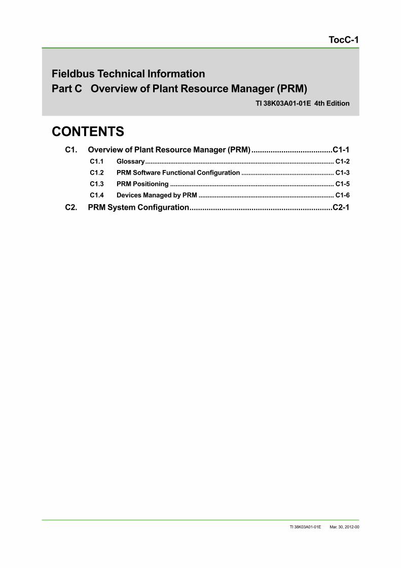
TocC-1
TI 38K03A01-01E
Fieldbus Technical InformationPart C Overview of Plant Resource Manager (PRM)
CONTENTSC1. Overview of Plant Resource Manager (PRM) ......................................C1-1
C1.1 Glossary .......................................................................................................... C1-2C1.2 PRM Software Functional Configuration .................................................... C1-3C1.3 PRM Positioning ............................................................................................ C1-5C1.4 Devices Managed by PRM ............................................................................ C1-6
C2. PRM System Configuration ...................................................................C2-1
TI 38K03A01-01E 4th Edition
Mar. 30, 2012-00

Blank Page

C1. Overview of Plant Resource Manager (PRM) C1-1
TI 38K03A01-01E
C1. Overview of Plant Resource Manager (PRM)
The Plant Resource Manager (PRM) performs plant asset management (PAM) to manage plant asset information online.
PRM performs intelligent operations for field devices with field communication functions: it accesses field devices remotely; and adjusts and diagnoses field devices’ parameters. PRM also manages various device maintenance information such as inspection schedules, inspection memos, and device configuration information of devices, which are utilized for device maintenance.
PRM can also acquire operating information of devices in a field via the fieldbus and control network (i.e. Vnet/IP or V net), which can then be used for maintenance of the field devices. PRM aims to improve operations and maintenance and optimizes the reliability and availability of plant assets by achieving greater predictability. PRM helps prevent downtime and reduces maintenance costs by helping both operators and maintenance people and the total cost of ownership (TCO) is reduced.
Mar. 30, 2012-00
C1. Overview of Plant Resource Manager (PRM) C1-2
TI 38K03A01-01E
C1.1 GlossaryIn addition to the standard terminology, the following terms are used in Part C.
Control ModuleThe minimum unit of instrument that performs a function in a system, and it does not function when decomposed. All control modules have unique serial numbers (device ID). i. e. Valve positioner, differential pressure transmitter, magnetic flowmeter, analyzer
Equipment ModuleA device consisting of one or more control modules. i. e. A valve’s main body and a valve positioner are referred to as “control module.” A control valve is referred to as “equipment module” when the main body and the positioner are combined.
Device IDA device ID is an identification number assigned to each physical device. It is often referred to as a manufacturing serial number. Each device is always given a uniquely numbered device ID when manufactured and it shall never change until it is scrapped. The same device ID is used when it is installed or dismantled, or reallocated in the plant. Conventional and static devices also need device IDs when registering them to the device master list.
Physical Device (PD) Tag NameA PD tag name, or device tag, is a logical name assigned to a control or equipment module. It is determined based on the functions that the control or equipment module performs and where in the plant it is installed. The device tag names comply with the names described in the plant design documents such as piping and instrument diagrams (P & ID). In case the allocation of the control or equipment module is changed, the device tag name also changes.
Node addressA unique address number specified within a segment.
Device with Field Communication FunctionControl modules which support digital communication function compliant with the FOUNDATION fieldbus, HART, PROFIBUS and ISA 100.11a wireless standards.
Conventional DeviceA control module, or a field device, of analog type such as 4-to-20 mA, 1 to 5 V, or mV input/output. A conventional device does not have any digital communication functions. A pneumatic control module may be also referred as a conventional device.
Static DeviceA static equipment without electric circuits or active elements. i.e. Orifice plate, pressure gauge, heat exchanger
Plug & Play FunctionWhen control modules with FF, HART, PROFIBUS, and wireless communication functions are automatically recognized when connected to a field network, thus simplifying the database registration.
Mar. 30, 2012-00
C1. Overview of Plant Resource Manager (PRM) C1-3
TI 38K03A01-01E
C1.2 PRM Software Functional ConfigurationA PRM system consists of the following three software products. An example of the PRM software configuration is shown on the following page.
PRM Server• Enters and displays maintenance and historical information
• Set and display field device parameters.
• Implements centralized device information management by creating device master (device profile), inspection record and schedule, spare parts lists, and so on.
• Acquires real-time device alarms & events 24 hours a day, and saves them to the database. The operating status of field devices can be monitored continuously.
PRM Client• Serves as a human interface function for PRM - user-friendly Windows-based operating
environment, with explorer-like “navigator” for selecting a specific device.
• Uses bidirectional, fully digitalized field networks such as FOUNDATION fieldbus, HART, PROFIBUS, and ISA 100.11a wireless. Performs automatic device recognition and registration (plug & play), monitors device status, displays device alarms & events, allows device parameters tuning, and performs device diagnosis.
• Device icon changes its color depending on the device status, which provides an intuitive and easy-to-understand overview of the device operating status.
• Both conventional analog devices and fieldbus devices can be registered for centralized asset management.
• Third-party software can be integrated as PLUG-IN applications such as Device Viewer. PRM Client launches a tuning tool or a diagnostic tool that is originally designed by the device vendors.
Mar. 30, 2012-00
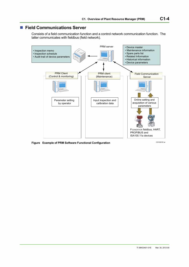
C1. Overview of Plant Resource Manager (PRM) C1-4
TI 38K03A01-01E
Field Communications ServerConsists of a field communication function and a control network communication function. The latter communicates with fieldbus (field network).
C010201E.ai
• Inspection memo• Inspection schedule• Audit trail of device parameters
• Device master• Maintenance information• Spare parts list• Related Information• Historical information• Device parameters
PRM server
PRM Client(Control & monitoring)
PRM client(Maintenance)
Field Communication Server
Parameter setting by operator
Input inspection and calibration data
Online setting and acquisition of various
parameters
FOUNDATION fieldbus, HART, PROFIBUS and ISA100.11a devices
Figure Example of PRM Software Functional Configuration
Mar. 30, 2012-00
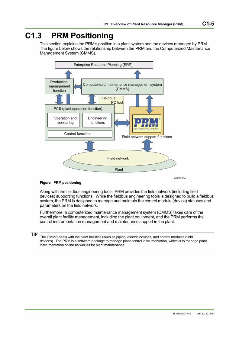
C1. Overview of Plant Resource Manager (PRM) C1-5
TI 38K03A01-01E
C1.3 PRM PositioningThis section explains the PRM’s position in a plant system and the devices managed by PRM. The figure below shows the relationship between the PRM and the Computerized Maintenance Management System (CMMS).
C010301E.ai
Enterprise Resource Planning (ERP)
Computerized maintenance management system(CMMS)
Production management
function
Fieldbus PC tool
PCS (plant operation function)
Control functions
Engineeringfunctions
Operation andmonitoring
Field network support functions
Field network
Plant
Figure PRM positioning
Along with the fieldbus engineering tools, PRM provides the field network (including field devices) supporting functions. While the fieldbus engineering tools is designed to build a fieldbus system, the PRM is designed to manage and maintain the control module (device) statuses and parameters on the field network. Furthermore, a computerized maintenance management system (CMMS) takes care of the overall plant facility management, including the plant equipment, and the PRM performs the control instrumentation management and maintenance support in the plant.
TIPThe CMMS deals with the plant facilities (such as piping, electric devices, and control modules (field devices). The PRM is a software package to manage plant control instrumentation, which is to manage plant instrumentation online as well as for plant maintenance.
Mar. 30, 2012-00
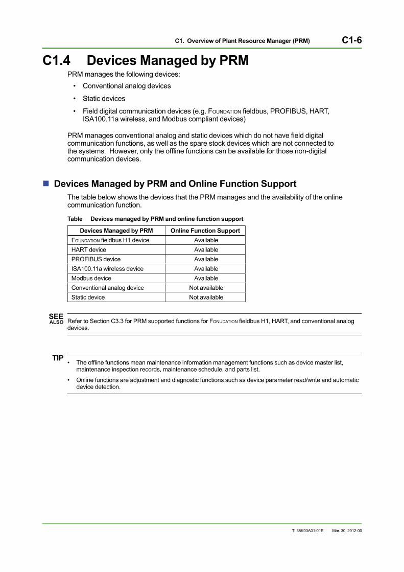
C1. Overview of Plant Resource Manager (PRM) C1-6
TI 38K03A01-01E
C1.4 Devices Managed by PRMPRM manages the following devices:
• Conventional analog devices
• Static devices
• Field digital communication devices (e.g. FOUNDATION fieldbus, PROFIBUS, HART, ISA100.11a wireless, and Modbus compliant devices)
PRM manages conventional analog and static devices which do not have field digital communication functions, as well as the spare stock devices which are not connected to the systems. However, only the offline functions can be available for those non-digital communication devices.
Devices Managed by PRM and Online Function SupportThe table below shows the devices that the PRM manages and the availability of the online communication function.
Table Devices managed by PRM and online function support
Devices Managed by PRM Online Function Support FOUNDATION fieldbus H1 device AvailableHART device AvailablePROFIBUS device Available ISA100.11a wireless device AvailableModbus device AvailableConventional analog device Not availableStatic device Not available
SEE ALSO Refer to Section C3.3 for PRM supported functions for FONUDATION fieldbus H1, HART, and conventional analog
devices.
TIP• The offline functions mean maintenance information management functions such as device master list, maintenance inspection records, maintenance schedule, and parts list.
• Online functions are adjustment and diagnostic functions such as device parameter read/write and automatic device detection.
Mar. 30, 2012-00
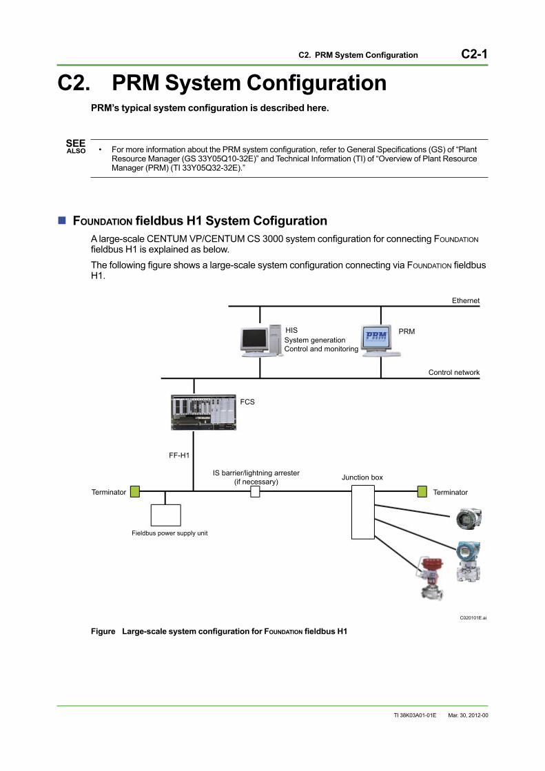
C2. PRM System Configuration C2-1
TI 38K03A01-01E
C2. PRM System ConfigurationPRM’s typical system configuration is described here.
SEE ALSO • For more information about the PRM system configuration, refer to General Specifications (GS) of “Plant
Resource Manager (GS 33Y05Q10-32E)” and Technical Information (TI) of “Overview of Plant Resource Manager (PRM) (TI 33Y05Q32-32E).”
FOUNDATION fieldbus H1 System Cofiguration A large-scale CENTUM VP/CENTUM CS 3000 system configuration for connecting FOUNDATION fieldbus H1 is explained as below. The following figure shows a large-scale system configuration connecting via FOUNDATION fieldbus H1.
C020101E.ai
FCS
Control network
HIS
Terminator Terminator
Fieldbus power supply unit
IS barrier/lightning arrester (if necessary) Junction box
FF-H1
Ethernet
PRMSystem generationControl and monitoring
Figure Large-scale system configuration for FOUNDATION fieldbus H1
Mar. 30, 2012-00

Blank Page
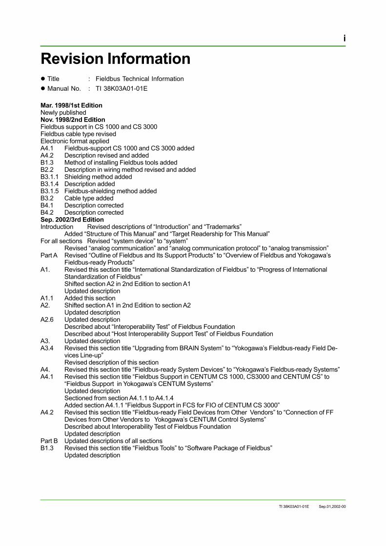
i
TI 38K03A01-01E
Revision Information Title : Fieldbus Technical Information Manual No. : TI 38K03A01-01E
Mar. 1998/1st EditionNewly publishedNov. 1998/2nd EditionFieldbus support in CS 1000 and CS 3000Fieldbus cable type revisedElectronic format appliedA4.1 Fieldbus-support CS 1000 and CS 3000 addedA4.2 Description revised and addedB1.3 Method of installing Fieldbus tools addedB2.2 Description in wiring method revised and addedB3.1.1 Shielding method addedB3.1.4 Description addedB3.1.5 Fieldbus-shielding method addedB3.2 Cable type addedB4.1 Description correctedB4.2 Description correctedSep. 2002/3rd EditionIntroduction Revised descriptions of “Introduction” and “Trademarks” Added “Structure of This Manual” and “Target Readership for This Manual” For all sections Revised “system device” to “system” Revised “analog communication” and “analog communication protocol” to “analog transmission”Part A Revised “Outline of Fieldbus and Its Support Products” to “Overview of Fieldbus and Yokogawa’s
Fieldbus-ready Products”A1. Revised this section title “International Standardization of Fieldbus” to “Progress of International
Standardization of Fieldbus” Shifted section A2 in 2nd Edition to section A1 Updated description A1.1 Added this sectionA2. Shifted section A1 in 2nd Edition to section A2 Updated descriptionA2.6 Updated description Described about “Interoperability Test” of Fieldbus Foundation Described about “Host Interoperability Support Test” of Fieldbus Foundation A3. Updated descriptionA3.4 Revised this section title “Upgrading from BRAIN System” to “Yokogawa’s Fieldbus-ready Field De-
vices Line-up” Revised description of this section A4. Revised this section title “Fieldbus-ready System Devices” to “Yokogawa’s Fieldbus-ready Systems”A4.1 Revised this section title “Fieldbus Support in CENTUM CS 1000, CS3000 and CENTUM CS” to
“Fieldbus Support in Yokogawa’s CENTUM Systems” Updated description Sectioned from section A4.1.1 to A4.1.4 Added section A4.1.1 “Fieldbus Support in FCS for FIO of CENTUM CS 3000” A4.2 Revised this section title “Fieldbus-ready Field Devices from Other Vendors” to “Connection of FF
Devices from Other Vendors to Yokogawa’s CENTUM Control Systems” Described about Interoperability Test of Fieldbus Foundation Updated descriptionPart B Updated descriptions of all sectionsB1.3 Revised this section title “Fieldbus Tools” to “Software Package of Fieldbus” Updated description
Sep.01,2002-00

ii
TI 38K03A01-01E
B2.2 Updated description Sectioned from section B2.2.1 to B2.2.4 Described about limit and restriction items in sections B2.2.1 and B2.2.2 B3.1 Revised this section title “New Construction of Fieldbus” to “New Construction of Fieldbus Process
Control System” Updated descriptionB5.4 Revised this section title “Future Maintenance” to “Evolution of Maintenance” Updated descriptionPart C Added this part
Mar. 2012/4th EditionRevised and updated all pages.
Mar. 30, 2012-00

Written by Yokogawa Electric Corporation
Published by Yokogawa Electric Corporation 2-9-32 Nakacho, Musashino-shi, Tokyo 180-8750, JAPAN
Printed by KOHOKU PUBLISHING & PRINTING INC.
Subject to change without notice.


![Profibus PA Fieldbus Display [ Revision 2 ] and Fieldbus ... Instruments... · Profibus PA Fieldbus Display [ Revision 2 ] and Fieldbus Indicator Fieldbus Interface Guide. ... Siemens](https://img.pdfslide.us/doc/110x75/5b2fe38e7f8b9ae16e8da83d/profibus-pa-fieldbus-display-revision-2-and-fieldbus-instruments.jpg)