Embed Size (px)
Citation preview
MAUSAM, 61, 1 (January 2010), 81-94
551.507.362.2
Technical feasibility on reception of VHRR signals from
Kalpana-1 satellite in the event of contingency with the existing operational ground receiving system
J. K. S. YADAV, A. K. CHAKARBORTY and R. K. GIRI
India Meteorological Department, New Delhi – 110 003, India
(Received 28 August 2009, Modified 25 September 2009)
e mail : [email protected]
lkj & Hkkjr ekSle foKku foHkkx dk jk"Vªh; mixzg ekSle dsUnz jk"Vªh; mixzgksa dh Ja[kyk ds
dYiuk&1@ bulSV }kjk izsf"kr fd, x, ekSle oSKkfud vk¡dM+ksa ds ladsrksa dks izkIr djus rFkk ekSle oSKkfud] i;kZoj.kh; ,oa tyok;q fLFkfr;ksa dk ekWuhVju djus ds fy, fofHkUu izdkj ds ekSle foKkfud mRiknksa dks rS;kj djus gsrq vk¡dM+ksa dk lalk/ku djus esaa egRoiw.kZ Hkwfedk fuHkk jgk gSA bl le; mixzg ds ladsr ekSle Hkou ifjlj] ubZ fnYyh esa fLFkr Hkkjr ekSle foKku foHkkx ds bulSV Hkw&dsUnz esa yxk, x, 7-5 eh- O;kl ds iSjkCkWkfyd fM’k ,aVhuk ds ek/;e ls izkIr fd, tk jgs gSaA
bl 'kks/k i= esa bl Hkw&dsUnz esa miyC/k NksVs O;kl ¼3-8 eh-½ ds iSjkckWfyd fM’k ,aVhuk ls dYiuk&1 ds
oh- ,p- vkj- vkj- ladsrksa dks izkIr fd;k tk jgk gS vkSj mUgsa lalkf/kr djus dk iz;kl fd;k x;k gSA vfrfjDr 2 Mh- ch- ekftZu dks fn[kku ds fy, lS)kfUrd :i ls vko’;d fyad dSydqys’ku cuk, x, vkSj mixzg ls fp= dks xzg.k djus ds fy, og iz;kZIr gksaxsaA geus bl ifj.kke dh rqyuk bl le; ekStwn 7-5 eh- O;kl ds ,aVhuk ds lkFk Hkh dh vkSj ;g Ikk;k fd 3-8 eh- ds ,aVhuk ls izkIr fd, x, mixzg ds fp=ksa dh xq.koRrk Hkh mruh gh vPNh gSA
bl v/;;u dk mÌs’; Hkkjr ekSle foKku foHkkx esa ekStwnk vk/kkjHkwr lajpuk dk mi;ksx djrs gq, bl
le; fo|eku 7-5 eh- O;kl ds iSjkckWfyd fM’k ,aVhuk esa fdlh vkdfLed ?kVuk dks /;ku esa j[krs gq, cSdvi ,aVhuk dk izpkyukRed :i ls rS;kj j[kuk gSA
ABSTRACT. National Satellite Meteorological Center (NSMC), of India Meteorological Department is
performing the vital role of receiving signals of meteorological data transmitted by KALPANA-1/INSAT series of national satellites and processing the data to generate various meteorological products for monitoring meteorological, environmental and climatological conditions. The satellite signals are currently being received through a 7.5 m diameter parabolic dish antenna installed at INSAT Earth Station of IMD located at Mausam Bhawan Complex, New Delhi.
In this study an attempt has been made to receive and process the VHRR signals of KALPANA-1 through a smaller
(3.8m) diameter parabolic dish antenna available at earth station .The link calculations have been made to show extra 2 db margin what is theoretically required and it will be sufficient for image capturing. We had also compared the result with existing 7.5m diameter antenna and observe that quality of satellite pictures received with 3.8m diameter antenna are also equally good.
The purpose of this study is to keep in operational readiness a backup antenna for the reception of KALPANA-1 in
the event of any unforseen contingency with the existing 7.5m diameter parabolic dish antenna, using the existing infrastructure of IMD.
Key words – Effective isotropic radiated power (EIRP), Link Budget and VHRR.
1. Introduction
Earth station unit of satellite meteorology division is
functioning since the launch of INSAT-2 series of
indigenous satellites from 1992 onwards.This earth station was initially designed, developed and implemented as a project and commissioned by Space Applications Center Ahmedabad (ISRO). It has a 7.5m diameter X-Y mounted
(81)

82 MAUSAM, 61, 1 (January 2010)
Fig. 1. Block schematic of ground receiving system
solid dish parabolic antenna having a cassegrin feed with a capability to receive meteorological data from the INSAT-2 series of satellites (INSAT-2A, INSAT-2B and INSAT-2E).The earth station also had a capability of transmitting processed cloud imageries data to the S-band transponders onboard INSAT for broadcast over the Indian region. Due to some technical reasons, this antenna is being used for reception purpose only for INSAT signals in extended C band around 4.5GHz since last more than 10 years. This antenna had been modified later on for the use of INSAT-1D reception in May 2002, subsequently this earth station was again put up in use for VHRR signal reception of exclusive meteorological satellite KALPANA-1 (METSAT) in September, 2002 and till date we are receiving the VHRR signals of Kalpana-1 for our day-to-day operational meteorological services.
Considering the need for keeping in operational readiness, another backup antenna for reception of VHRR signals from KALPANA-1 in the event of any unforseen contingency with existing old 7.5m diameter antenna at earth station, we have made an attempt to use a 3.8 meter diameter parabolic dish antenna with prime focus feed which was spare and it was being used basically as a test antenna for reception of data from automatic rain gauges (ARG) in collaboration with SAC, Ahmedabad. The
purpose is to keep it as a backup antenna for reception of VHRR signals in case of any emergency due to any unforeseen reasons.
Keeping in view the results of on orbit testing of KALPANA-1, where it was shown that the measured EIRP of VHRR transmitter is 3dB better than the specification. An attempt had been made to receive VHRR data in addition with DRT signals with 3.8 meter diameter parabolic antenna. This was thought to be technically feasible due to availability of higher VHRR EIRP from the satellite.
As per theoretical calculations we expect a 2db margin in the overall link .For reception of VHRR signals from KALPANA-1 using 3.8m-diameter antenna this has been actually demonstrated in the present study. As a result of this the problem of availability of backup arrangement has been solved using the existing equipments in the department. 2. Necessity for using 3.8m Antenna in IMD for
reception of KALPANA-1 VHRR
The backup requirement for INSAT-3A satellite data reception in IMD is already complete. Antenna currently in use are 6.1 m diameter parabolic dish antenna for
YADAV et al. : VHRR SIGNALS FROM KALPANA – I SATELLITE 83
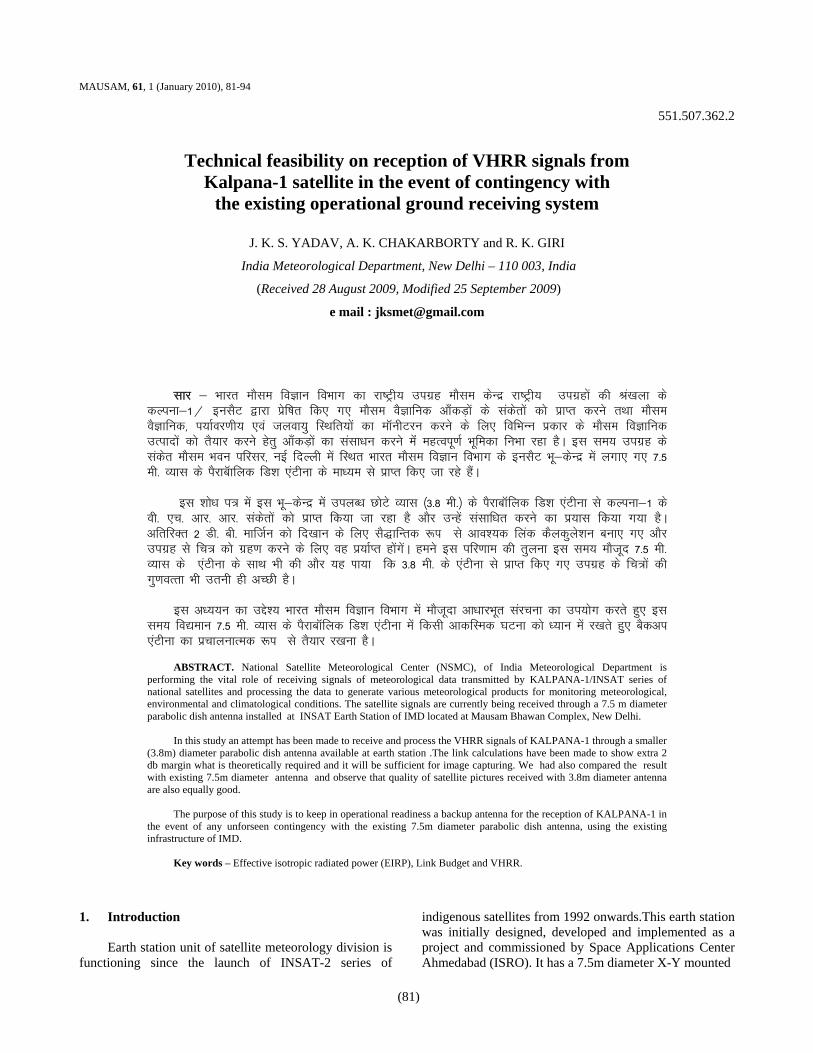
Fig. 2. IF spectrum of Kalpana-1 VHRR signal with 3.8 Antenna
IF (KALPANA – I)
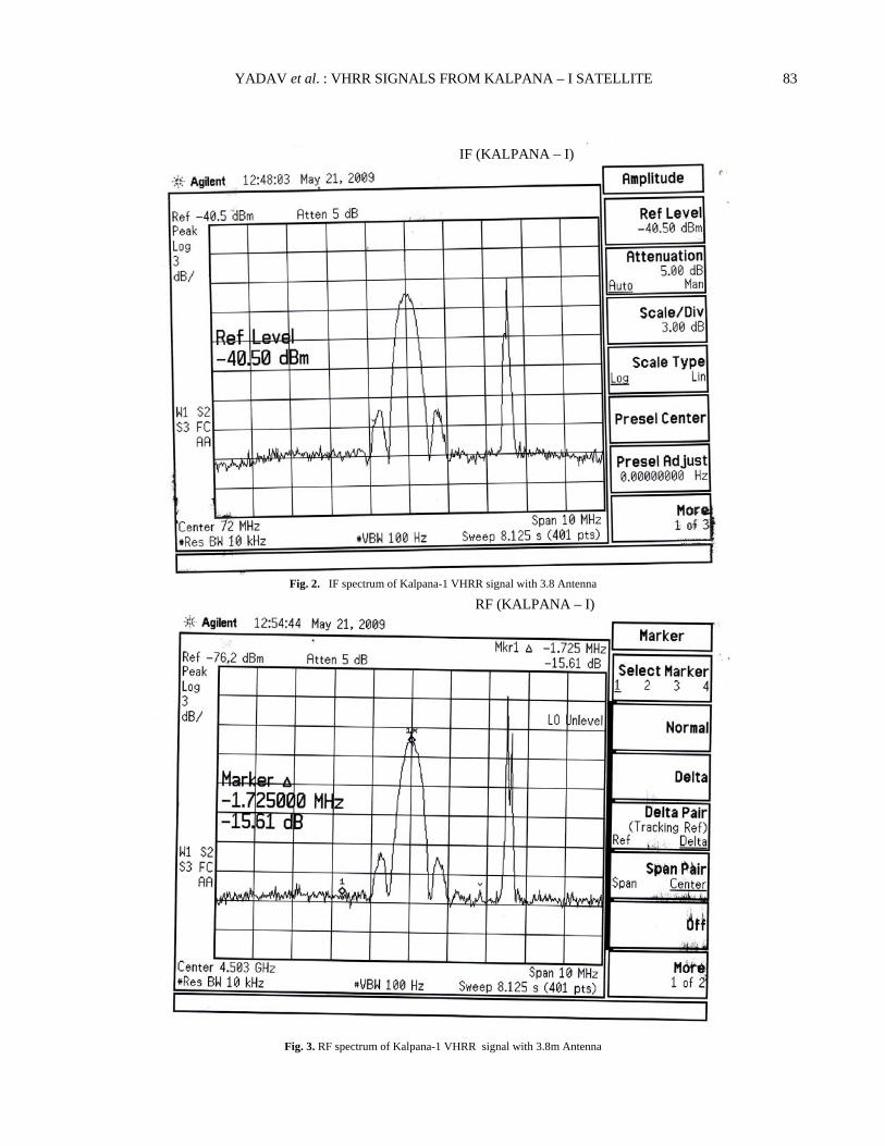
Fig. 3. RF spectrum of Kalpana-1 VHRR signal with 3.8m Antenna
RF (KALPANA – I)
84 MAUSAM, 61, 1 (January 2010)
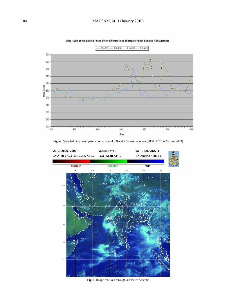
Fig. 4. Sampled Gray level pixel comparison of 3.8 and 7.5-meter antenna (0800 UTC on 23 June 2009)
Fig. 5. Image received through 3.8 meter Antenna

YADAV et al. : VHRR SIGNALS FROM KALPANA – I SATELLITE 85
Fig. 6. Image received from 7.5 meter Antenna
Fig. 7. Image received from 3.8 meter Antenna
86 MAUSAM, 61, 1 (January 2010)
Fig. 8. Image received from 7.5 meter Antenna
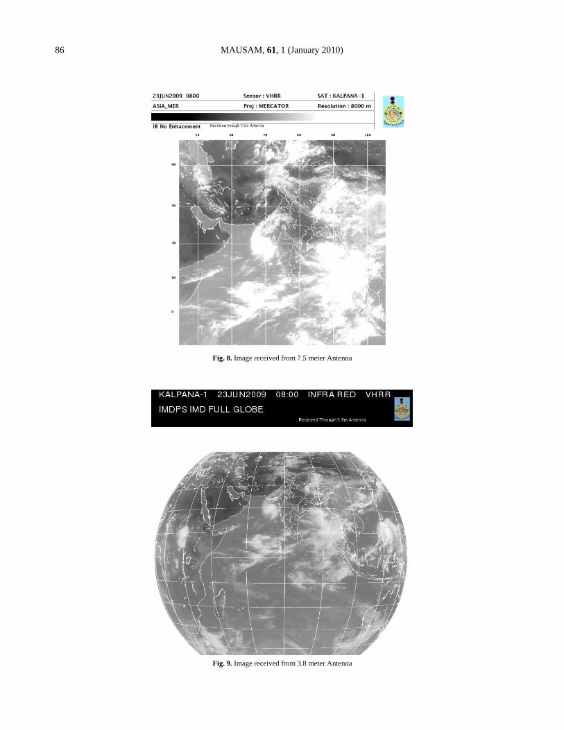
Fig. 9. Image received from 3.8 meter Antenna

YADAV et al. : VHRR SIGNALS FROM KALPANA – I SATELLITE 87
Fig. 10. Image received from 7.5 meter Antenna
reception of INSAT-3A signal with a backup up of 6.3 m parabolic dish antenna. We have observed that the KALPANA-1 satellite performance is better than that of specification (EIRP of METSAT) and we get an extra 3dB power in the VHRR which can be usefully exploited for reception of VHRR signal from KALPANA using a smaller antenna size of 3.8 meter. Keeping this in view, we have explored the technical feasibility of using 3.8m diameter antenna as a backup for KALPANA-1 VHRR with existing infrastructure. 3. Theoretical analysis of signal reception
RF signal of –150dBm is received through 3.8m diameter parabolic dish antenna with a prime focus feed and is fed to LNA unit having noise temperature of 90 deg.K and 60 dB gain. This RF signal is further down converted to generate 70 + -20 MHZ IF. There is a dual conversion inside the demodulator with a first local oscillator (5.58-5.88 GHz) and second local oscillator (1150 MHz). Thereafter, it is demodulated from the carrier 4503.5 MHz of Kalpana VHRR having data rate of 526.5 kbps. The data received is in the form of RS-422 compatible electrical signal. The signals received are differential clock and differential data which is converted
to TTL form. VHRR is a BPSK modulated NRZ-S encoded signal with a bit rate of 526.5 kbps for input to Bit synchronizer for onward processing through main computers for generation of satellite imageries.
For 3.8 meter diameter antenna the technical parameters like, G/T of earth station, Antenna gain, Eb/No, have been calculated and compared with the ideal characteristics of extended C band antenna of 7.5 m diameter which is shown in Appendix.
An extra margin of 2.0dBHz as shown in Appendix is obtained from the available 3.8m diameter parabolic dish antenna to receive the VHRR signal from Kalpana-1 satellite.
The RF/IF spectrum of KALPANA-1 VHRR signal with 3.8m diameter antenna is shown in the Fig. 2 and Fig. 3 respectively which were taken on 21 May 2009.
4. Operations in the inclined orbit mode with
3.8 meter antenna from tracking point of view
Tracking is necessary when the satellite goes in inclined orbit after end of life (EOL) of satellite when
88 MAUSAM, 61, 1 (January 2010)
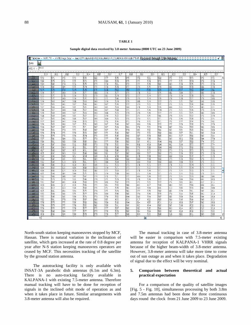
TABLE 1
Sample digital data received by 3.8 meter Antenna (0800 UTC on 23 June 2009)
North-south station keeping manoeuvres stopped by MCF, Hassan. There is natural variation in the inclination of satellite, which gets increased at the rate of 0.8 degree per year after N-S station keeping manoeuvres operators are ceased by MCF. This necessities tracking of the satellite by the ground station antenna.
The autotracking facility is only available with INSAT-3A parabolic dish antennas (6.1m and 6.3m). There is no auto-tracking facility available in KALPANA-1 with existing 7.5-meter antenna. Therefore manual tracking will have to be done for reception of signals in the inclined orbit mode of operation as and when it takes place in future. Similar arrangements with 3.8-meter antenna will also be required.
The manual tracking in case of 3.8-meter antenna will be easier in comparison with 7.5-meter existing antenna for reception of KALPANA-1 VHRR signals because of the higher beam-width of 3.8-meter antenna. However, 3.8-meter antenna will take more time to come out of sun outage as and when it takes place. Degradation of signal due to the effect will be very nominal. 5. Comparison between theoretical and actual
practical expectation For a comparison of the quality of satellite images
[Fig. 5 - Fig. 10], simultaneous processing by both 3.8m and 7.5m antennas had been done for three continuous days round the clock from 21 June 2009 to 23 June 2009.
YADAV et al. : VHRR SIGNALS FROM KALPANA – I SATELLITE 89
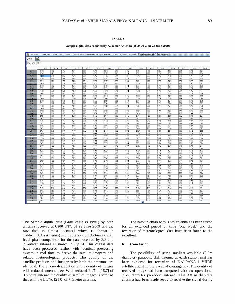
TABLE 2
Sample digital data received by 7.5 meter Antenna (0800 UTC on 23 June 2009)
The Sample digital data (Gray value vs Pixel) by both antenna received at 0800 UTC of 23 June 2009 and the raw data is almost identical which is shown in Table 1 (3.8m Antenna) and Table 2 (7.5m Antenna).Gray level pixel comparison for the data received by 3.8 and 7.5-meter antenna is shown in Fig. 4. This digital data have been processed further with identical processing system in real time to derive the satellite imagery and related meteorological products. The quality of the satellite products and imageries by both the antennas are identical. There is no degradation in the quality of images with reduced antenna size. With reduced Eb/No [16.7] of 3.8meter antenna the quality of satellite images is same as that with the Eb/No [21.0] of 7.5meter antenna.
The backup chain with 3.8m antenna has been tested for an extended period of time (one week) and the reception of meteorological data have been found to the excellent.
6. Conclusion
The possibility of using smallest available (3.8m diameter) parabolic dish antenna at earth station unit has been explored for reception of KALPANA-1 VHRR satellite signal in the event of contingency .The quality of received image had been compared with the operational 7.5m diameter parabolic antenna. This 3.8 m diameter antenna had been made ready to receive the signal during
90 MAUSAM, 61, 1 (January 2010)
any failure of 7.5m operational antennas and it is made as a backup antenna for reception of KALPANA-1 satellite signal at the earth station of India Meteorological Department, Mausam Bhawan, New Delhi. This backup arrangement has been actually demonstrated to work practically for reception of VHRR signal from KALPANA-1. Acknowledgements
We would like to thank AVM Dr. Ajit Tyagi, Director General of Meteorology, India Meteorological Department for his support and encouragement for this
study. We would also like to thanks Shri R. C. Bhatia, Retd. ADGM (SatMet) and Shri A. K. Sharma, DDGM (SatMet) for necessary guidance and discussions to complete this study. We are also grateful for the cooperation of all the members of Earth station unit and satellite division.
References
METSAT Report, 2000, “Configuration No. ISRO-ISAC-METSAT-PR-0154.
Wayne Tomasi, 2006, “Advance Electronics and Communication System”.
Appendix (a) G/T (figure of merit) of earth station had been calculated using gain equation and system noise temperature i.e.,
G/T = G – 10log (T system) (b) Antenna gain, A(db) = 10 log [(3.14) D/]2
Where
D = antenna diameter
= wave length
= 0.55(antenna efficiency). since C = F × where C = 3 × 1010 cm/sec F = 4.5 × 10⁹ per sec and D= 3.8 × 100cm = 380cm Therefore = 6.7 cm Hence [(3.14) D/]2 = 31697.5
YADAV et al. : VHRR SIGNALS FROM KALPANA – I SATELLITE 91
and log[(3.14) D/]2 = 4.24 Hence, Antenna gain, A(db) = 10 × 4.24
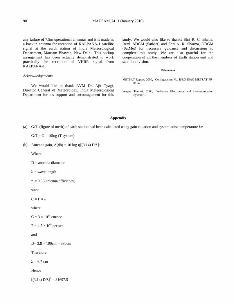
= 42.4 db This can also be verified from standard antenna gain and diameter graph as shown below in Fig. A1 [Wayne,
2006].
Fig. A1. Antenna gain as a function of antenna diameter for different frequency
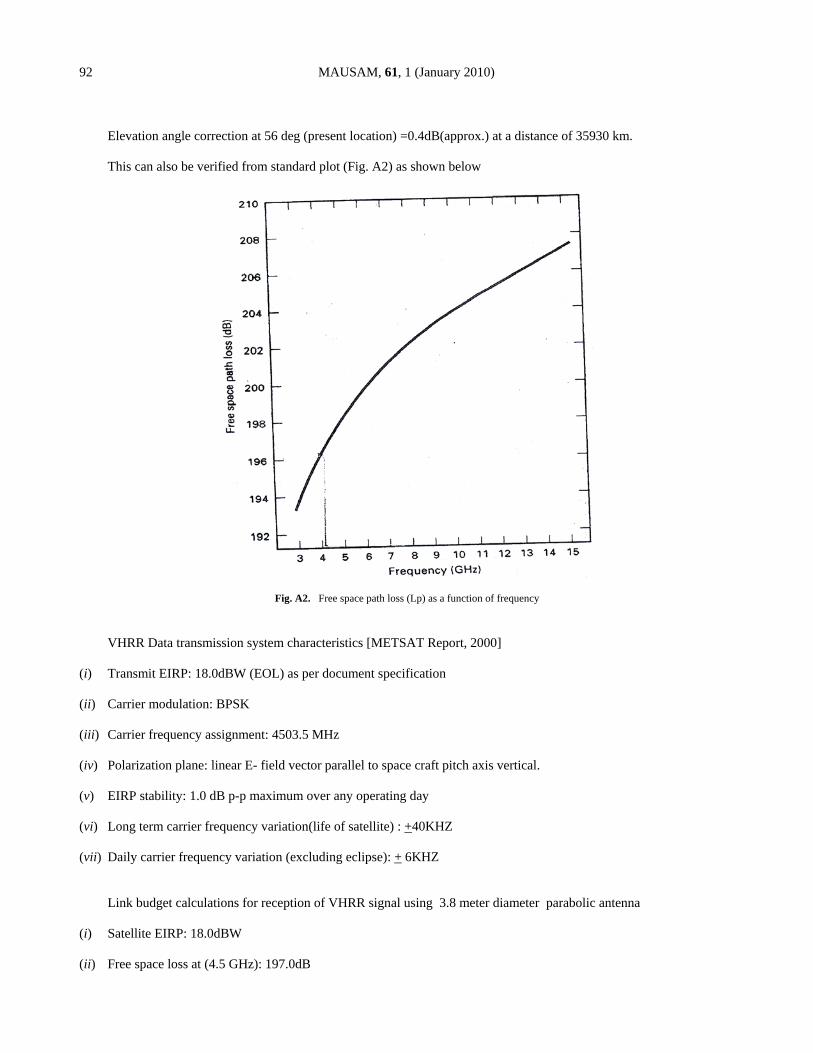
(c) Free space path loss, Lp
Lp = 183.5 + 20 log f(GHz) = 183.5 + 20 log(4.5) = 183.5 + 13.06 = 196.56 dB = 197 dB (approx)
92 MAUSAM, 61, 1 (January 2010)
Elevation angle correction at 56 deg (present location) =0.4dB(approx.) at a distance of 35930 km. This can also be verified from standard plot (Fig. A2) as shown below
Fig. A2. Free space path loss (Lp) as a function of frequency
VHRR Data transmission system characteristics [METSAT Report, 2000] (i) Transmit EIRP: 18.0dBW (EOL) as per document specification (ii) Carrier modulation: BPSK (iii) Carrier frequency assignment: 4503.5 MHz (iv) Polarization plane: linear E- field vector parallel to space craft pitch axis vertical. (v) EIRP stability: 1.0 dB p-p maximum over any operating day (vi) Long term carrier frequency variation(life of satellite) : +40KHZ (vii) Daily carrier frequency variation (excluding eclipse): + 6KHZ Link budget calculations for reception of VHRR signal using 3.8 meter diameter parabolic antenna (i) Satellite EIRP: 18.0dBW (ii) Free space loss at (4.5 GHz): 197.0dB

YADAV et al. : VHRR SIGNALS FROM KALPANA – I SATELLITE 93
(iii) Data rate: 526.5kbps/57.2dBHz (iv) Eb/No required = 12.8db (from standard Fig. A3) (v) C/No required: 70 dBHz (for Kalpana VHRR)
Fig. A3. Eb/No as a function of Error probability
Therefore G/T for 3.8 m antenna will be
G/T = G – 10 log(Tsystem)
= 42.4 –20
= 22.4dB/deg. K where (G antenna = 42.4dB and T system=100 deg. K at 5 deg. elevation up to Low noise amplifier) and
From the link budget equation,
C/No = EIRP-Path loss + G/T-K

94 MAUSAM, 61, 1 (January 2010)
= 18.0 –197 +22.4 + 228.6
= 72.0 dBHz
Required C/No is 70.0 dBHz
Therefore, the extra available margin in C/No for 3.8m antenna is 72.0-70.0 = 2 dBHz


![Home []...Office furniture Boardroom 32 33 Office furniture Reception Desks VENEER AND MELAMINE L-shape reception unit Curved/Modular Reception Unit Straight reception unit MELAMINE](https://img.pdfslide.us/doc/110x75/5f45d717fcf7fd212578b44d/home-office-furniture-boardroom-32-33-office-furniture-reception-desks-veneer.jpg)