Embed Size (px)
Citation preview
Technical Evaluation Report TER 1308-11
FastenMaster® ThruLOK® Pole Barn Header Connection
OMG, Inc.
DBA FastenMaster®
Product: ThruLOK® Screw Bolt Fastening
System
Issue Date: September 13, 2013
Revision Date: August 18, 2021
Subject to Renewal: October 1, 2022
TER 1308-11
FASTENMASTER® THRULOK® POLE BARN HEADER CONNECTION © 2021 DRJ ENGINEERING, LLC
SUBJECT TO RENEWAL 10/1/2022 PAGE 2 OF 12
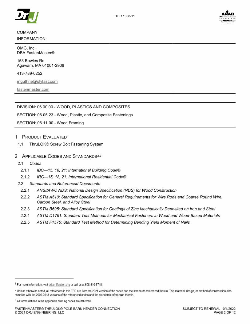
COMPANY INFORMATION:
OMG, Inc. DBA FastenMaster®
153 Bowles Rd Agawam, MA 01001-2908
413-789-0252
fastenmaster.com
DIVISION: 06 00 00 - WOOD, PLASTICS AND COMPOSITES
SECTION: 06 05 23 - Wood, Plastic, and Composite Fastenings
SECTION: 06 11 00 - Wood Framing
1 PRODUCT EVALUATED1 1.1 ThruLOK® Screw Bolt Fastening System
2 APPLICABLE CODES AND STANDARDS2,3 2.1 Codes
2.1.1 IBC—15, 18, 21: International Building Code® 2.1.2 IRC—15, 18, 21: International Residential Code®
2.2 Standards and Referenced Documents 2.2.1 ANSI/AWC NDS: National Design Specification (NDS) for Wood Construction 2.2.2 ASTM A510: Standard Specification for General Requirements for Wire Rods and Coarse Round Wire,
Carbon Steel, and Alloy Steel 2.2.3 ASTM B695: Standard Specification for Coatings of Zinc Mechanically Deposited on Iron and Steel 2.2.4 ASTM D1761: Standard Test Methods for Mechanical Fasteners in Wood and Wood-Based Materials 2.2.5 ASTM F1575: Standard Test Method for Determining Bending Yield Moment of Nails
1 For more information, visit drjcertification.org or call us at 608-310-6748. 2 Unless otherwise noted, all references in this TER are from the 2021 version of the codes and the standards referenced therein. This material, design, or method of construction also complies with the 2000-2018 versions of the referenced codes and the standards referenced therein. 3 All terms defined in the applicable building codes are italicized.
TER 1308-11
FASTENMASTER® THRULOK® POLE BARN HEADER CONNECTION © 2021 DRJ ENGINEERING, LLC
SUBJECT TO RENEWAL 10/1/2022 PAGE 3 OF 12
3 PERFORMANCE EVALUATION 3.1 The ThruLOK® Screw Bolt Fastening System was evaluated to determine its ability to provide code complying
attachment of horizontal roof headers to vertical columns (posts) to resist roof to header to column gravity loads and the associated load paths.
3.1.1 The evaluation includes both single header and double header configurations. 3.2 Use of the ThruLOK® Screw Bolt Fastening System for other connections is outside the scope of this technical
evaluation report (TER). 3.3 Any code compliance issues not specifically addressed in this section are outside the scope of this TER. 3.4 Any engineering evaluation conducted for this TER was performed within DrJ’s ANAB “accredited ICS code
scope” and/or the defined professional engineering scope of work on the dates provided herein.
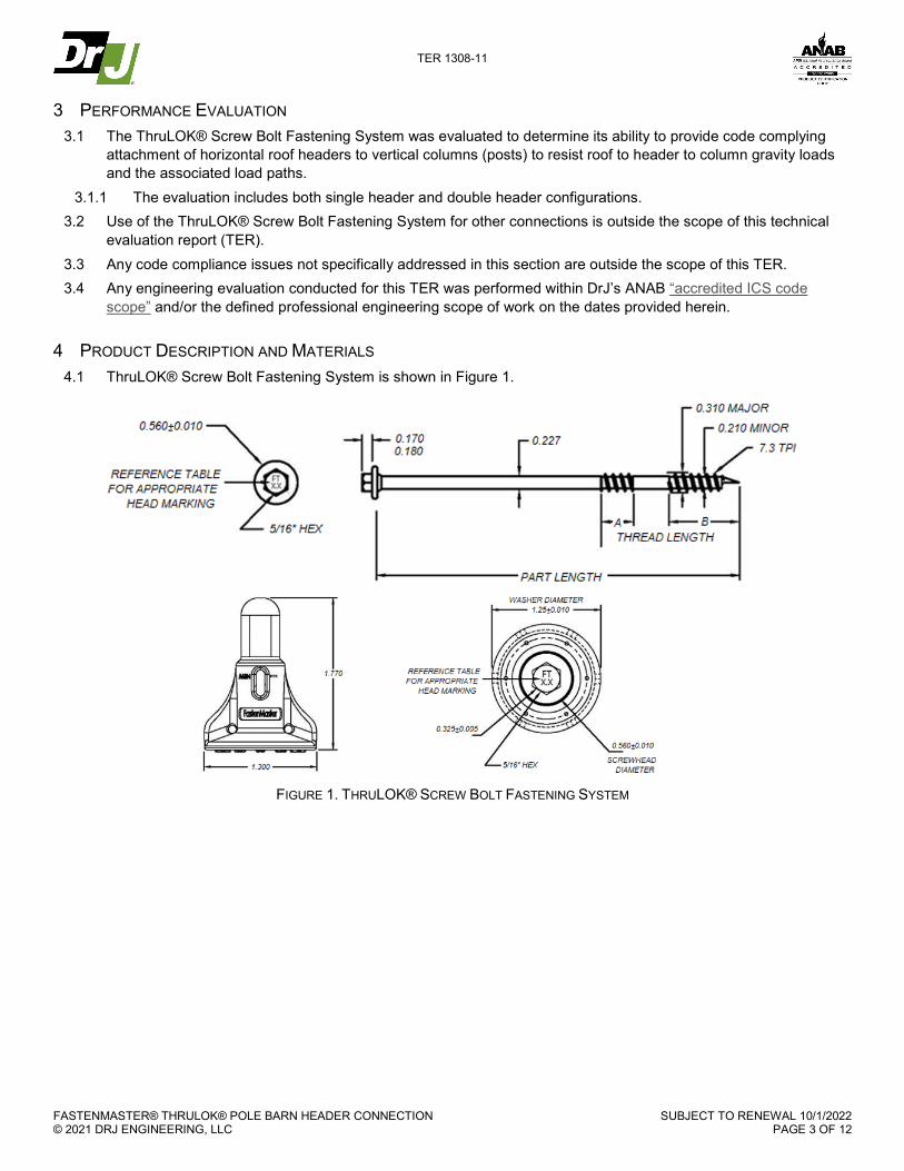
4 PRODUCT DESCRIPTION AND MATERIALS 4.1 ThruLOK® Screw Bolt Fastening System is shown in Figure 1.
FIGURE 1. THRULOK® SCREW BOLT FASTENING SYSTEM

TER 1308-11
FASTENMASTER® THRULOK® POLE BARN HEADER CONNECTION © 2021 DRJ ENGINEERING, LLC
SUBJECT TO RENEWAL 10/1/2022 PAGE 4 OF 12
4.1.1 The FastenMaster® ThruLOK® series fasteners listed in Table 1 were evaluated. TABLE 1. FASTENER SPECIFICATIONS
Fastener Name
Fastener Designation
Head Marking
Length1 (in)
Length of Thread2 (in)
Unthreaded Shank
Diameter (in)
Minor Thread (Root)
Diameter (in)
Allowable Bending
Yield3 (psi) A B
ThruLOK® THR912 FT9.5 9.5 0.56 1.2 0.227 0.210 218,400
THR008 FT8.0 8.0 0.56 1.2 0.227 0.210 218,400 SI: 1 in = 25.4 mm, 1 psi = 0.00689 MPa 1. Measured from the underside of the head to the point of the tip. 2. The thread lengths given for the ThruLOK® are for zones A and B, as depicted in Figure 1. 3. Determined in accordance with methods specified in ASTM F1575, based on minor thread diameter using a 5% offset of the load displacement curves developed from bending
tests.
4.1.2 ThruLOK® fastener heads have a 5/16" hex drive. 4.1.3 Allowable bending yield and critical dimensions are found in Table 1. 4.1.4 ThruLOK® fasteners have a proprietary cutting point and are supplied with a ThruLOK® washer and nut. 4.1.5 ThruLOK® fasteners are manufactured with carbon steel grade 1022 or 10B21 wire conforming to ASTM
A510 with a minimum ultimate tensile strength of 60 ksi. 4.1.6 ThruLOK® fasteners are coated with mechanically applied zinc in accordance with ASTM B695, Class 55 as
specified in IRC Section R317.3.1. 4.2 Fasteners are approved for use in fire-retardant-treated lumber, provided the conditions set forth by the fire
retardant treated lumber manufacturer are met, including appropriate strength reductions.
5 APPLICATIONS 5.1 Where the application exceeds the limitations set forth herein, design shall be permitted in accordance with
accepted engineering procedures, experience, and technical judgment. 5.2 Single Header Configuration
5.2.1 Figure 2 shows a single header connection using ThruLOK® fasteners to resist single shear of one header on one side of one column.
FIGURE 2. THRULOK® SCREW BOLT FASTENING SYSTEM – ROOF TO HEADER DETAIL

TER 1308-11
FASTENMASTER® THRULOK® POLE BARN HEADER CONNECTION © 2021 DRJ ENGINEERING, LLC
SUBJECT TO RENEWAL 10/1/2022 PAGE 5 OF 12
5.2.1 For the header configuration shown in Figure 2, it is assumed that the interior header will receive 75% of the load and the exterior header will receive 25% of the load.
5.2.2 Table 2 provides the number of ThruLOK® fasteners needed for various snow loading conditions. TABLE 2. SINGLE SHEAR – TRUSS BEARING ON ONE HEADER TO ONE COLUMN1,3,4,5
Building Width Including 1'
Overhang Each End (ft)
Species2 (Pressure Treated) Truss
Spacing (ft)
Column Spacing
(ft)
Number of 8" ThruLOK® Fasteners per Header
Loading (Snow + TC Dead + BC Dead) PSF
20+10+5 = 35 30+10+5 = 45 40+10+5 = 55
24
Hem-Fir
4 8
4 6 6
Douglas-Fir 4 4 6
Mixed Southern Yellow Pine 4 4 6
28
Hem-Fir
4 8
6 6 8
Douglas-Fir 4 6 6
Mixed Southern Yellow Pine 4 6 6
32
Hem-Fir
4 8
6 8 8
Douglas-Fir 6 6 8
Mixed Southern Yellow Pine 4 6 8
36
Hem-Fir
4 8
6 8 -
Douglas-Fir 6 6 8
Mixed Southern Yellow Pine 6 6 8
40
Hem-Fir
4 8
6 8 -
Douglas-Fir 6 8 -
Mixed Southern Yellow Pine 6 6 8
44
Hem-Fir
4 8
8 - -
Douglas-Fir 6 8 -
Mixed Southern Yellow Pine 6 8 -
48
Hem-Fir
4 8
8 - -
Douglas-Fir 8 8 -
Mixed Southern Yellow Pine 6 8 -
52
Hem-Fir
4 8
8 - -
Douglas-Fir 8 - -
Mixed Southern Yellow Pine 8 8 - SI: 1 in = 25.4 mm, 1 psf = 0.0479 kN/m2 1. Fastener designs were evaluated under NDS wet service (also known as wet use) conditions to account for the effects of higher header and/or column moisture content. 2. Lumber used shall be either treated Southern Pine, treated Hem-Fir, or treated Douglas Fir. 3. Connection design assumes that the header supports one truss located at midspan of the header. Trusses located at the columns shall be supported by bearing on the
column and shall not apply loads to the header. 4. Design of all wood members (e.g., columns/posts, headers, trusses, girts, knee braces) and connections not shown are by others. 5. See Section 5.4 for information on minimum required edge and end distances.
TER 1308-11
FASTENMASTER® THRULOK® POLE BARN HEADER CONNECTION © 2021 DRJ ENGINEERING, LLC
SUBJECT TO RENEWAL 10/1/2022 PAGE 6 OF 12
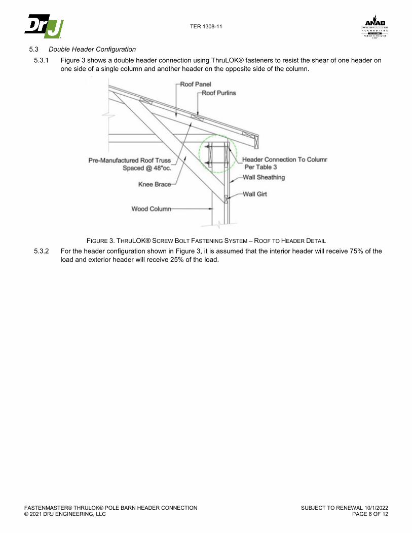
5.3 Double Header Configuration 5.3.1 Figure 3 shows a double header connection using ThruLOK® fasteners to resist the shear of one header on
one side of a single column and another header on the opposite side of the column.
FIGURE 3. THRULOK® SCREW BOLT FASTENING SYSTEM – ROOF TO HEADER DETAIL
5.3.2 For the header configuration shown in Figure 3, it is assumed that the interior header will receive 75% of the load and exterior header will receive 25% of the load.

TER 1308-11
FASTENMASTER® THRULOK® POLE BARN HEADER CONNECTION © 2021 DRJ ENGINEERING, LLC
SUBJECT TO RENEWAL 10/1/2022 PAGE 7 OF 12
5.3.3 Table 3 provides the number of ThruLOK® fasteners needed for various snow loading conditions. TABLE 3. TWO-BEAM SHEAR – TRUSS BEARING ON TWO HEADERS CONNECTED TO ONE COLUMN1,3,4,5
Building Width Including 1'
Overhang Each End (ft)
Species2 (Pressure Treated) Truss
Spacing (ft)
Column Spacing
(ft)
Number of 9½" ThruLOK® Fasteners per Header
Loading (Snow + TC Dead + BC Dead) PSF
20+10+5 = 35 30+10+5 = 45 40+10+5 = 55
24
Hem-Fir
4 8
4 4 6
Douglas-Fir 4 4 4
Mixed Southern Yellow Pine 4 4 4
28
Hem-Fir
4 8
4 6 6
Douglas-Fir 4 4 6
Mixed Southern Yellow Pine 4 4 4
32
Hem-Fir
4 8
4 6 6
Douglas-Fir 4 4 6
Mixed Southern Yellow Pine 4 4 6
36
Hem-Fir
4 8
6 6 8
Douglas-Fir 4 6 6
Mixed Southern Yellow Pine 4 6 6
40
Hem-Fir
4 8
6 6 8
Douglas-Fir 4 6 8
Mixed Southern Yellow Pine 4 6 6
44
Hem-Fir
4 8
6 8 8
Douglas-Fir 6 8 8
Mixed Southern Yellow Pine 4 6 8
48
Hem-Fir
4 8
6 8 -
Douglas-Fir 6 6 8
Mixed Southern Yellow Pine 6 6 8
52
Hem-Fir
4 8
6 8 -
Douglas-Fir 6 8 8
Mixed Southern Yellow Pine 6 6 8 SI: 1 in = 25.4 mm, 1 psf = 0.0479 kN/m2 1. Fastener designs were evaluated under NDS wet service (also known as wet use) conditions to account for the effects of higher header and/or column moisture content. 2. Lumber used shall be either treated Southern Pine, treated Hem-Fir, or treated Douglas Fir. 3. Connection design assumes that the header supports one truss located at midspan of the header. Trusses located at the columns shall be supported by bearing on the
column and shall not apply loads to the header. 4. See Section 5.2 for information on minimum required edge and end distances. 5. Design of all wood members (e.g., columns/posts, headers, trusses, girts) and connections not shown are by others.

TER 1308-11
FASTENMASTER® THRULOK® POLE BARN HEADER CONNECTION © 2021 DRJ ENGINEERING, LLC
SUBJECT TO RENEWAL 10/1/2022 PAGE 8 OF 12
5.4 Figure 4 and Table 4 provide the required edge and end distances for the applications described in this TER.
FIGURE 4. THRULOK® SCREW BOLT FASTENING SYSTEM – EDGE, END, AND SPACING REQUIREMENTS
TER 1308-11
FASTENMASTER® THRULOK® POLE BARN HEADER CONNECTION © 2021 DRJ ENGINEERING, LLC
SUBJECT TO RENEWAL 10/1/2022 PAGE 9 OF 12
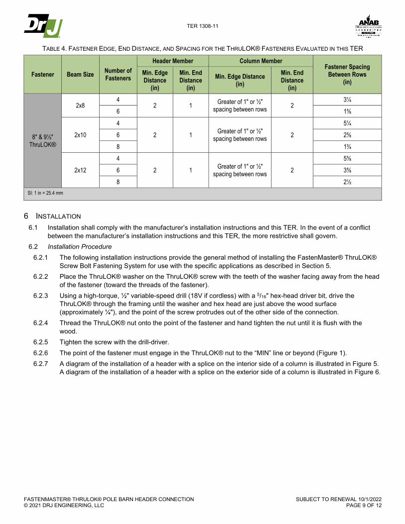
TABLE 4. FASTENER EDGE, END DISTANCE, AND SPACING FOR THE THRULOK® FASTENERS EVALUATED IN THIS TER
Fastener Beam Size Number of Fasteners
Header Member Column Member Fastener Spacing
Between Rows (in)
Min. Edge Distance
(in)
Min. End Distance
(in) Min. Edge Distance
(in) Min. End Distance
(in)
8" & 9½" ThruLOK®
2x8 4
2 1 Greater of 1" or ½" spacing between rows 2
3¼
6 1⅝
2x10
4
2 1 Greater of 1" or ½" spacing between rows 2
5¼
6 2⅝
8 1¾
2x12
4
2 1 Greater of 1" or ½" spacing between rows 2
5⅝
6 3⅝
8 2½ SI: 1 in = 25.4 mm
6 INSTALLATION 6.1 Installation shall comply with the manufacturer’s installation instructions and this TER. In the event of a conflict
between the manufacturer’s installation instructions and this TER, the more restrictive shall govern. 6.2 Installation Procedure
6.2.1 The following installation instructions provide the general method of installing the FastenMaster® ThruLOK® Screw Bolt Fastening System for use with the specific applications as described in Section 5.
6.2.2 Place the ThruLOK® washer on the ThruLOK® screw with the teeth of the washer facing away from the head of the fastener (toward the threads of the fastener).
6.2.3 Using a high-torque, ½" variable-speed drill (18V if cordless) with a 5/16" hex-head driver bit, drive the ThruLOK® through the framing until the washer and hex head are just above the wood surface (approximately ¼"), and the point of the screw protrudes out of the other side of the connection.
6.2.4 Thread the ThruLOK® nut onto the point of the fastener and hand tighten the nut until it is flush with the wood.
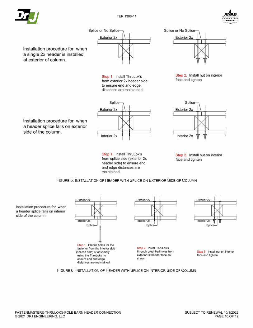
6.2.5 Tighten the screw with the drill-driver. 6.2.6 The point of the fastener must engage in the ThruLOK® nut to the “MIN” line or beyond (Figure 1). 6.2.7 A diagram of the installation of a header with a splice on the interior side of a column is illustrated in Figure 5.
A diagram of the installation of a header with a splice on the exterior side of a column is illustrated in Figure 6.
TER 1308-11
FASTENMASTER® THRULOK® POLE BARN HEADER CONNECTION © 2021 DRJ ENGINEERING, LLC
SUBJECT TO RENEWAL 10/1/2022 PAGE 10 OF 12
FIGURE 5. INSTALLATION OF HEADER WITH SPLICE ON EXTERIOR SIDE OF COLUMN
FIGURE 6. INSTALLATION OF HEADER WITH SPLICE ON INTERIOR SIDE OF COLUMN
TER 1308-11
FASTENMASTER® THRULOK® POLE BARN HEADER CONNECTION © 2021 DRJ ENGINEERING, LLC
SUBJECT TO RENEWAL 10/1/2022 PAGE 11 OF 12
7 SUBSTANTIATING DATA 7.1 Testing has been performed under the supervision of a professional engineer and/or under the requirements of
ISO/IEC 17025 as follows: 7.1.1 Lateral resistance testing in accordance with ASTM D1761 7.1.2 Bending yield testing in accordance with ASTM F1575
7.2 Information contained herein is the result of testing and/or data analysis by sources which conform to IBC Section 1703 and/or professional engineering regulations. DrJ relies upon accurate data to perform its ISO/IEC 17065 evaluations.
7.3 Where appropriate, DrJ’s analysis is based on provisions that have been codified into law through state or local adoption of codes and standards. The providers of the codes and standards are legally responsible for their content. DrJ analysis may use code-adopted provisions as a control sample. A control sample versus a test sample establishes a product as being equivalent to that prescribed in this code in quality, strength, effectiveness, fire resistance, durability, and safety. Where the accuracy of the provisions provided herein is reliant upon the published properties of materials, DrJ relies upon the grade mark, grade stamp, mill certificate, and/or test data provided by material suppliers to be minimum properties. DrJ analysis relies upon these properties to be accurate.
8 FINDINGS 8.1 When used and installed in accordance with this TER and the manufacturer’s installation instructions, the
product(s) listed in Section 1.1 are approved for the following: 8.1.1 Fastening roof headers to columns for the conditions specified in Table 2 and Table 3
8.2 This product has been evaluated in the context of the codes listed in Section 2 and is compliant with all known state and local building codes. Where there are known variations in state or local codes applicable to this TER, they are listed here.
8.2.1 No known variations 8.3 Building codes require data from valid research reports be obtained from approved sources (i.e., licensed
registered design professionals [RDPs]). 8.3.1 Building official approval of a licensed RDP is performed by verifying the RDP and/or their business entity is
listed by the licensing board of the relevant jurisdiction. 8.4 Agencies who are accredited through ISO/IEC 17065 have met the code requirements for approval by the
building official. DrJ is an ISO/IEC 17065 ANAB-Accredited Product Certification Body – Accreditation #1131 and employs RDPs.
8.5 Through ANAB accreditation and the IAF MLA, DrJ certification can be used to obtain product approval in any jurisdiction or country that has IAF MLA Members & Signatories to meet the Purpose of the MLA – “certified once, accepted everywhere.”
8.6 IBC Section 104.11 (IRC Section R104.11 and IFC Section 104.104 are similar) states:
104.11 Alternative materials, design and methods of construction and equipment. The provisions of this code are not intended to prevent the installation of any material or to prohibit any design or method of construction not specifically prescribed by this code…Where the alternative material, design or method of construction is not approved, the building official shall respond in writing, stating the reasons the alternative was not approved.
4 2018 IFC Section 104.9
TER 1308-11
FASTENMASTER® THRULOK® POLE BARN HEADER CONNECTION © 2021 DRJ ENGINEERING, LLC
SUBJECT TO RENEWAL 10/1/2022 PAGE 12 OF 12
9 CONDITIONS OF USE 9.1 The ThruLOK® Screw Bolt Fastening System covered by this TER shall be subject to the following conditions:
9.1.1 This TER and the installation instructions, when required by a code official, shall be available at the time of permit application.
9.1.2 Installation shall comply with this TER and the manufacturer’s installation instructions. In the event of a conflict between this TER and the manufacturer’s installation instructions, the more restrictive shall govern.
9.1.3 For conditions not covered in this TER, connections shall be designed in accordance with generally accepted engineering practice.
9.1.4 Manufacturer’s installation instructions shall be followed as provided in Section 6 and at fastenmaster.com. 9.1.5 The ThruLOK® series fasteners are produced by OMG, Inc.'s facility located in Agawam, Massachusetts. 9.1.6 The fasteners are identified by the designation "ThruLOK®" on the packaging. The head of the ThruLOK®
fastener is marked with an "FT" followed by a number corresponding to the length of the fastener. 9.1.6.1 The packaging shall include OMG's name and address, fastener size, third-party inspection agency, and
this TER number. 9.1.7 The ThruLOK® series fasteners are produced under a quality control program subject to periodic inspections
in accordance with IBC Section 1703.5.2. 9.2 Where required by the building official, also known as the authority having jurisdiction (AHJ) in which the project is
to be constructed, this TER and the installation instructions shall be submitted at the time of permit application. 9.3 Any generally accepted engineering calculations needed to show compliance with this TER shall be submitted to
the AHJ for review and approval. 9.4 Design loads shall be determined in accordance with the building code adopted by the jurisdiction in which the
project is to be constructed and/or by the building designer (e.g., owner or RDP). 9.5 At a minimum, this product shall be installed per Section 6 of this TER. 9.6 This product has an internal quality control program and a third-party quality assurance program in accordance
with IBC Section 104.4 and Section 110.4 and IRC Section R104.4 and Section R109.2. 9.7 The actual design, suitability, and use of this TER, for any particular building, is the responsibility of the owner or
the owner's authorized agent. 9.8 This TER shall be reviewed for code compliance by the AHJ in concert with IBC Section 104. 9.9 The implementation of this TER for this product is dependent on the design, quality control, third-party quality
assurance, proper implementation of installation instructions, inspections required by IBC Section 110.3, and any other code or regulatory requirements that may apply.
10 IDENTIFICATION 10.1 The product(s) listed in Section 1.1 are identified by a label on the board or packaging material bearing the
manufacturer’s name, product name, TER number, and other information to confirm code compliance. 10.2 Additional technical information can be found at fastenmaster.com.
11 REVIEW SCHEDULE 11.1 This TER is subject to periodic review and revision. For the most recent version, visit drjcertification.org. 11.2 For information on the current status of this TER, contact DrJ Certification.