Embed Size (px)
Citation preview
Technical Evaluation Report TER 1105-01
Requirements for Attaching THERMAX™ XARMOR (ci)
Exterior Insulation & Three-Coat Stucco Cladding to Steel Stud Walls
DuPont Performance Building
Solutions
Product: THERMAX™ XARMOR (ci)
Exterior Insulation
Issue Date: September 9, 2011
Revision Date: December 17, 2019 Subject to Renewal: December 17, 2019
TER 1105-01: REQUIREMENTS FOR ATTACHING THERMAX™ XARMOR (CI)EXTERIOR INSULATION & THREE-COAT STUCCO CLADDING TO STEEL STUD WALLS
© 2019 DRJ ENGINEERING, LLC PAGE 2 OF 17
COMPANY INFORMATION:
DuPont Performance Building Solutions
1501 Larkin Center Dr Midland, MI 48642
989-638-8655
dupont.com
DIVISION: 06 00 00 - WOOD, PLASTICS AND COMPOSITES
SECTION: 06 16 00 - Sheathing
DIVISION: 07 00 00 - THERMAL AND MOISTURE PROTECTION
SECTION: 07 21 00 - Thermal Insulation
1 PRODUCT EVALUATED1 THERMAX™ XARMOR (ci) Exterior Insulation
2 APPLICABLE CODES AND STANDARDS2,3 Codes
2.1.1 IBC—12, 15, 18: International Building Code® 2.1.2 IRC—12, 15, 18: International Residential Code®
Standards and Referenced Documents 2.2.1 ASTM C1289: Standard Specification for Faced Rigid Cellular Polyisocyanurate Thermal Insulation Board 2.2.2 ASTM C518: Standard Test Method for Steady-State Thermal Transmission Properties by Means of the Heat
Flow Meter Apparatus 2.2.3 ASTM E2357: Standard Test Method for Determining Air Leakage Rate of Air Barrier Assemblies 2.2.4 ASTM E283: Standard Test Method for Determining Rate of Air Leakage Through Exterior Windows, Curtain
Walls, and Doors Under Specified Pressure Differences Across the Specimen 2.2.5 ASTM E330: Standard Test Method for Structural Performance of Exterior Windows, Doors, Skylights and
Curtain Walls by Uniform Static Air Pressure Difference
1 Building codes require data from valid research reports be obtained from approved sources. Agencies who are accredited through ISO/IEC 17065 have met the code requirements for approval by the building official. DrJ is an ISO/IEC 17065 ANSI-Accredited Product Certification Body – Accreditation #1131. Through ANSI accreditation and the IAF MLA, DrJ certification can be used to obtain product approval in any jurisdiction or country that has IAF MLA Members & Signatories to meet the Purpose of the MLA – “certified once, accepted everywhere.” Building official approval of a licensed registered design professional (RDP) is performed by verifying the RDP and/or their business entity complies with all professional engineering laws of the relevant jurisdiction. Therefore, the work of licensed RDPs is accepted by building officials, except when plan (i.e. peer) review finds an error with respect to a specific section of the code. Where this TER is not approved, the building official responds in writing stating the reasons for disapproval. For more information on any of these topics or our mission, product evaluation policies, product approval process, and engineering law, visit drjcertification.org or call us at 608-310-6748. 2 Unless otherwise noted, all references in this TER are from the 2018 version of the codes and the standards referenced therein (e.g., ASCE 7, NDS, ASTM). This material, design, or method of construction also complies with the 2000-2015 versions of the referenced codes and the standards referenced therein. 3 All terms defined in the applicable building codes are italicized.
TER 1105-01: REQUIREMENTS FOR ATTACHING THERMAX™ XARMOR (CI)EXTERIOR INSULATION & THREE-COAT STUCCO CLADDING TO STEEL STUD WALLS
© 2019 DRJ ENGINEERING, LLC PAGE 3 OF 17
2.2.6 ASTM E331: Standard Test Method for Water Penetration of Exterior Windows, Skylights, Doors, and Curtain Walls by Uniform Static Air Pressure Difference
2.2.7 SBCA ANSI/FS 100: Standard Requirements for Wind Pressure Resistance of Foam Plastic Insulating Sheathing Used in Exterior Wall Covering Assemblies
2.2.8 NFPA 285: Standard Fire Test Method for the Evaluation of Fire Propagation Characteristics of Exterior Nonload-bearing Wall Assemblies Containing Combustible Components
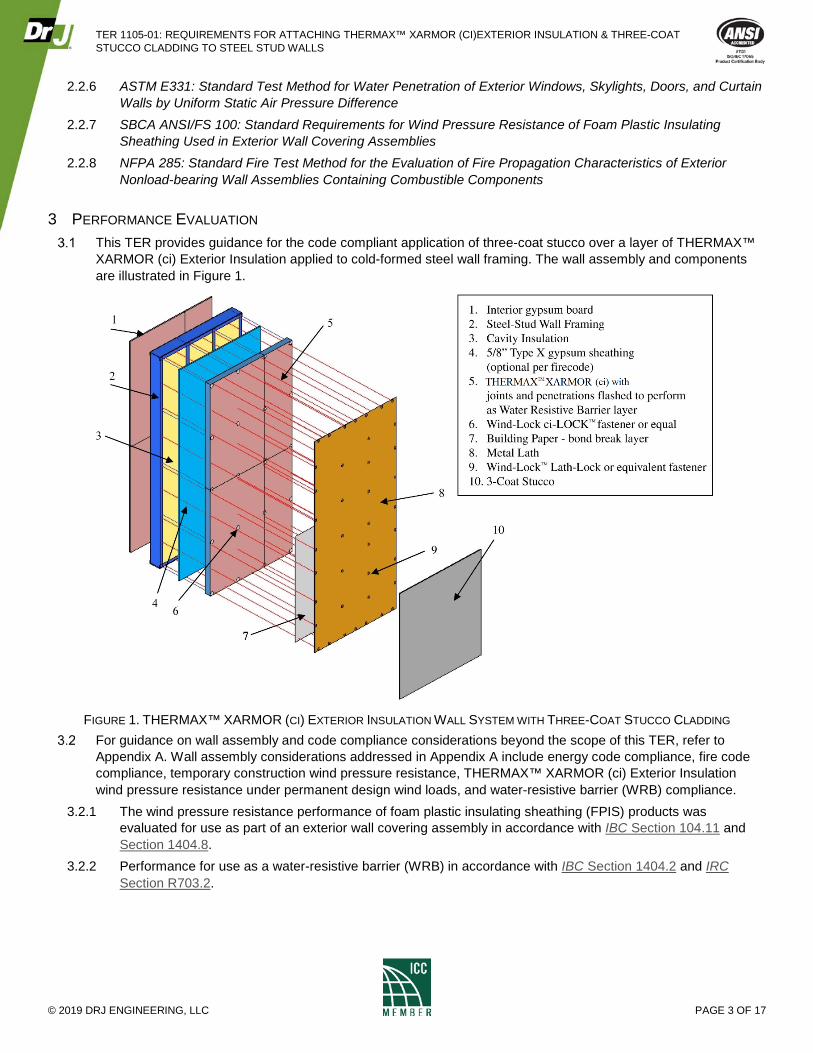
3 PERFORMANCE EVALUATION This TER provides guidance for the code compliant application of three-coat stucco over a layer of THERMAX™
XARMOR (ci) Exterior Insulation applied to cold-formed steel wall framing. The wall assembly and components are illustrated in Figure 1.
FIGURE 1. THERMAX™ XARMOR (CI) EXTERIOR INSULATION WALL SYSTEM WITH THREE-COAT STUCCO CLADDING
For guidance on wall assembly and code compliance considerations beyond the scope of this TER, refer to Appendix A. Wall assembly considerations addressed in Appendix A include energy code compliance, fire code compliance, temporary construction wind pressure resistance, THERMAX™ XARMOR (ci) Exterior Insulation wind pressure resistance under permanent design wind loads, and water-resistive barrier (WRB) compliance.
3.2.1 The wind pressure resistance performance of foam plastic insulating sheathing (FPIS) products was evaluated for use as part of an exterior wall covering assembly in accordance with IBC Section 104.11 and Section 1404.8.
3.2.2 Performance for use as a water-resistive barrier (WRB) in accordance with IBC Section 1404.2 and IRC Section R703.2.
TER 1105-01: REQUIREMENTS FOR ATTACHING THERMAX™ XARMOR (CI)EXTERIOR INSULATION & THREE-COAT STUCCO CLADDING TO STEEL STUD WALLS
© 2019 DRJ ENGINEERING, LLC PAGE 4 OF 17
3.2.3 Performance for use in an air barrier assembly in accordance with IRC Section N1102.4.1.1 and IECC Section R402.4.1.1 and Section C402.5.1.1.4
Any code compliance issues not specifically addressed in this section are outside the scope of this TER. Any engineering evaluation conducted for this TER was performed on the dates provided in this TER and within
DrJ’s professional scope of work.
4 PRODUCT DESCRIPTION AND MATERIALS THERMAX™ XARMOR (ci) Exterior Insulation is:
4.1.1 Made from polyisocyanurate (ISO) conforming to ASTM C1289 for Type I material 4.1.2 Available in various lengths and widths
4.1.2.1 Typically supplied in widths up to 48" and lengths of 96", 108", and 120" 4.1.3 Available in various thicknesses up to 4" 4.1.4 90-day aged R-value as measured in accordance with ASTM C518
4.1.4.1 6.5 per inch of thickness up to 2 inches 4.1.4.2 5.0 per inch of thickness every inch above 2 inches
5 APPLICATIONS Requirements for THERMAX™ XARMOR (ci) Exterior Insulation
5.1.1 Maximum Sheathing Thickness – the thickness of THERMAX™ XARMOR (ci) Exterior Insulation used in accordance with this TER shall not exceed 4".
5.1.2 Wall Sheathing Wind Pressure Resistance – when not installed as over-sheathing5, THERMAX™ XARMOR (ci) Exterior Insulation shall be sized in accordance with IRC Section R703.15 and Section R703.16 as applicable. For conditions that exceed the scope of the IRC, furring and/or cladding connections shall be designed using NDS yield limit equations and AWC TR12, except the reduction factor shall be a minimum of 3. Wind pressures shall be determined in accordance with IBC Section 1609.
5.1.3 Where the application exceeds the limitations set forth herein, design shall be permitted in accordance with accepted engineering procedures, experience, and technical judgment.
5.1.3.1 Refer to Appendix A for additional guidance. 5.1.4 Wall Sheathing Fastening – THERMAX™ XARMOR (ci) Exterior Insulation shall be attached to steel framing
to resist wind load experienced during construction. 5.1.4.1 The installer shall be responsible for providing adequate attachment for temporary wind load resistance
during construction, prior to installation of lath and three-coat stucco for permanent wind load resistance. 5.1.4.2 Refer to Appendix A and the manufacturer's installation instructions for guidance on fastening
THERMAX™ XARMOR (ci) Exterior Insulation to provide temporary wind load resistance during construction.
5.1.5 Water-Resistive Barrier Sheathing Detailing Requirements – where a separate code compliant WRB is not applied to the wall assembly, THERMAX™ XARMOR (ci) Exterior Insulation shall be installed in accordance with the manufacturer's installation instructions to perform as a WRB in accordance with IBC Section 1404.2.
4 2012 IECC Section C402.4.1.1 5 Over-sheathing occurs when THERMAX™ XARMOR (ci) Exterior Insulation is installed directly to the surface of a solid wall, such as concrete or masonry, or directly to the surface of a sheathing material (such as OSB or gypsum sheathing) that is separately attached to wall framing and capable of resisting the code-required design wind load. Where THERMAX™ XARMOR (ci) Exterior Insulation is installed directly to open cavity wall framing, the application is not over-sheathing.
TER 1105-01: REQUIREMENTS FOR ATTACHING THERMAX™ XARMOR (CI)EXTERIOR INSULATION & THREE-COAT STUCCO CLADDING TO STEEL STUD WALLS
© 2019 DRJ ENGINEERING, LLC PAGE 5 OF 17
5.1.5.1 All joints and penetrations shall be sealed using LIQUIDARMOR™–CM Flashing and Sealant and/or WEATHERMATE™ flashing tape, code compliant mechanical flashings, or equivalent.
5.1.5.2 Refer to Appendix A for additional guidance. 5.1.6 Blocking – when not installed as over-sheathing, THERMAX™ XARMOR (ci) Exterior Insulation shall be
installed directly to steel framing in a fully-blocked condition (i.e., all sheathing edges supported on framing or blocking) with a minimum ¾" bearing support at panel edges.
5.1.6.1 Exception: Where sheathing is installed with length axis (machine direction) perpendicular to studs, blocking at horizontal sheathing joints shall not be required.
5.1.7 Air Barrier – THERMAX™ XARMOR (ci) Exterior Insulation may be used as an air barrier material as prescribed in IRC Section N1102.4.1.1 and IECC Section R402.4.1.1 and Section C402.5.1 in accordance with ASTM E2357.
TABLE 1. THERMAX™ XARMOR (CI) EXTERIOR INSULATION AIR BARRIER PROPERTIES
Test Standard Result
ASTM E2357 THERMAX™ XARMOR (ci) < 0.02 (L/s-m2)1 1. Liter per second per square meter 2. Temperature during testing averaged 65°F
Requirements for Three-Coat Stucco Cladding 5.2.1 General – metal plaster base (lath) and three-coat stucco installation shall comply with IBC Section 2510 and
IBC Section 2512, the lath manufacturer’s installation instructions, and the additional requirements in Section 5.2.
5.2.2 Fastening Schedule – the minimum screw fastener size and maximum spacing shall comply with Table 2 or Section 5.2.1, whichever results in the more stringent fastening requirement. Refer to Appendix A for alternative lath fastener spacing subject to an approved design.
5.2.2.1 Screw fasteners and washers for woven wire metal lath shall comply with Section 5.3.3, and the length of screw shall provide for a minimum of three (3) threads penetrating through and beyond the steel framing member thickness.
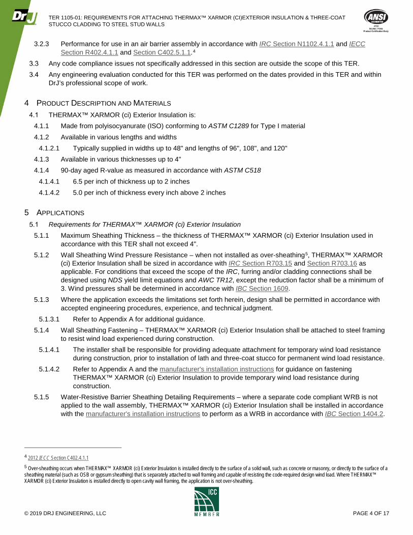
TABLE 2. MAXIMUM PERMISSIBLE THICKNESS OF THERMAX™ XARMOR (CI) EXTERIOR INSULATION BASED ON LATH SCREW FASTENER SIZE & SPACING
Lath Fastener Size & Steel Framing
Thickness
Lath Fastener Vertical Spacing Along Studs
(in)
Maximum Permissible Thickness of THERMAX™ XARMOR (ci) Exterior Insulation (in)
16" o.c. Stud Spacing 24" o.c. Stud Spacing
#8 screw into 33 mil steel or thicker
6 3 2
7 2 2
#10 screw into 33 mil steel
6 3 3
7 3 2
#10 screw into 43 mil steel or thicker
6 4 4
7 4 4 SI: 1 in = 25.4 mm, 1 lb = 4.45 N, 1 lb/ft = 0.0146 kN/m, 1 psf = 0.0479 kN/m2, 1 psi = 0.00689 MPa, 1 mph = 1.61 km/h 1. Lath fastener shall include a washer in accordance with Section 5.3.3. 2. Lath manufacturer’s installation instructions shall be used, if more stringent. 3. The contents of this table were created from information taken from the references listed in Section 7.6 and 7.7.
TER 1105-01: REQUIREMENTS FOR ATTACHING THERMAX™ XARMOR (CI)EXTERIOR INSULATION & THREE-COAT STUCCO CLADDING TO STEEL STUD WALLS
© 2019 DRJ ENGINEERING, LLC PAGE 6 OF 17
Material Specifications 5.3.1 Cold-Formed Steel Framing – cold-formed steel framing materials and fasteners shall comply with IBC
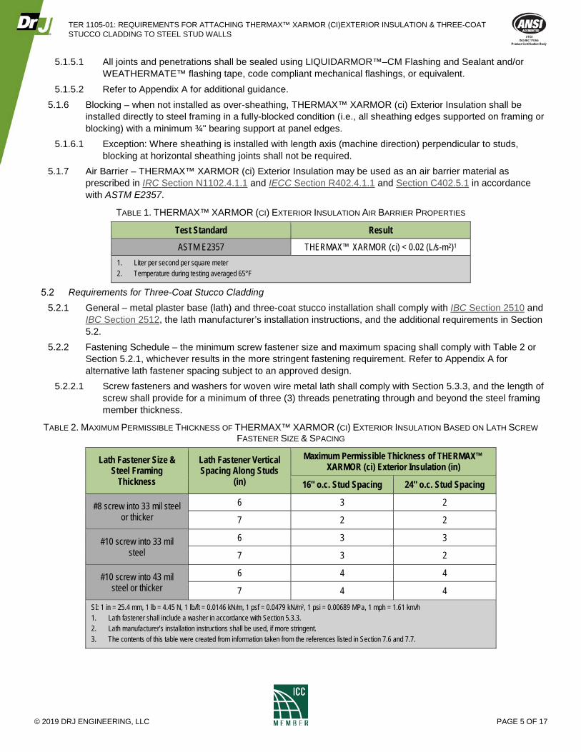
Section 22106 and Section 2211. 5.3.2 Wall Sheathing and Fasteners – THERMAX™ XARMOR (ci) Exterior Insulation wall sheathing shall comply
with ASTM C1289, Type I and the additional requirements of this TER. THERMAX™ XARMOR (ci) Exterior Insulation shall be fastened to steel framing using Wind-Lock® ci-LOCK US series screws with a ULP-302 plastic washer (Figure 2) or equivalent.
FIGURE 2. WIND-LOCK® CI-LOCK US SERIES ULP-302
PLASTIC WASHER
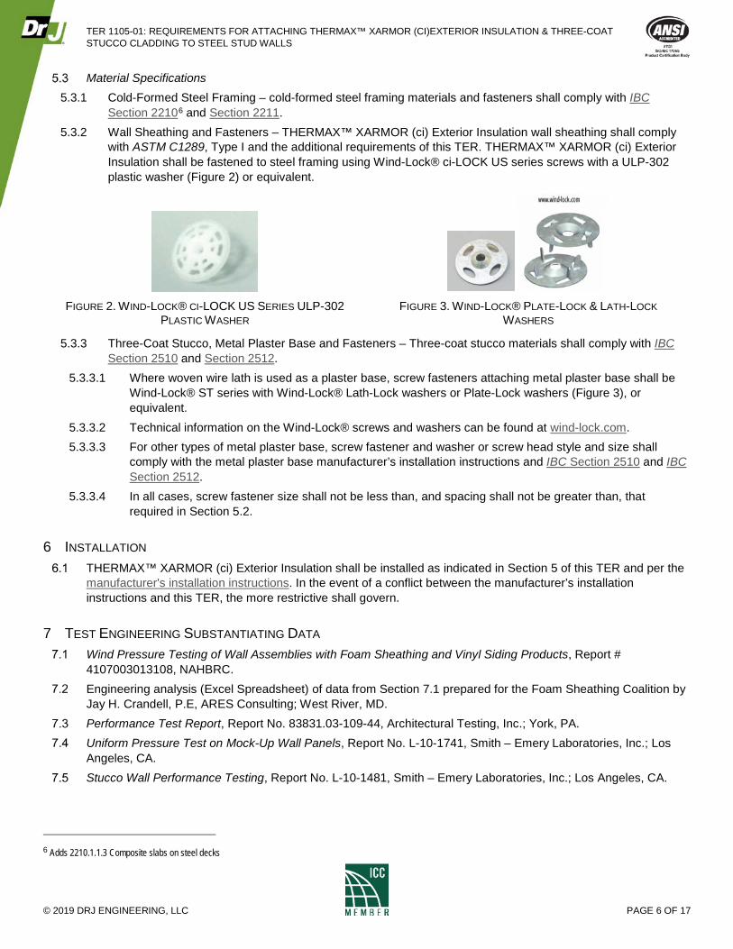
FIGURE 3. WIND-LOCK® PLATE-LOCK & LATH-LOCK
WASHERS
5.3.3 Three-Coat Stucco, Metal Plaster Base and Fasteners – Three-coat stucco materials shall comply with IBC Section 2510 and Section 2512.
5.3.3.1 Where woven wire lath is used as a plaster base, screw fasteners attaching metal plaster base shall be Wind-Lock® ST series with Wind-Lock® Lath-Lock washers or Plate-Lock washers (Figure 3), or equivalent.
5.3.3.2 Technical information on the Wind-Lock® screws and washers can be found at wind-lock.com. 5.3.3.3 For other types of metal plaster base, screw fastener and washer or screw head style and size shall
comply with the metal plaster base manufacturer’s installation instructions and IBC Section 2510 and IBC Section 2512.
5.3.3.4 In all cases, screw fastener size shall not be less than, and spacing shall not be greater than, that required in Section 5.2.
6 INSTALLATION THERMAX™ XARMOR (ci) Exterior Insulation shall be installed as indicated in Section 5 of this TER and per the
manufacturer's installation instructions. In the event of a conflict between the manufacturer’s installation instructions and this TER, the more restrictive shall govern.
7 TEST ENGINEERING SUBSTANTIATING DATA Wind Pressure Testing of Wall Assemblies with Foam Sheathing and Vinyl Siding Products, Report #
4107003013108, NAHBRC. Engineering analysis (Excel Spreadsheet) of data from Section 7.1 prepared for the Foam Sheathing Coalition by
Jay H. Crandell, P.E, ARES Consulting; West River, MD. Performance Test Report, Report No. 83831.03-109-44, Architectural Testing, Inc.; York, PA. Uniform Pressure Test on Mock-Up Wall Panels, Report No. L-10-1741, Smith – Emery Laboratories, Inc.; Los
Angeles, CA. Stucco Wall Performance Testing, Report No. L-10-1481, Smith – Emery Laboratories, Inc.; Los Angeles, CA.
6 Adds 2210.1.1.3 Composite slabs on steel decks
TER 1105-01: REQUIREMENTS FOR ATTACHING THERMAX™ XARMOR (CI)EXTERIOR INSULATION & THREE-COAT STUCCO CLADDING TO STEEL STUD WALLS
© 2019 DRJ ENGINEERING, LLC PAGE 7 OF 17
Fastening Systems for Continuous Insulation, Final Report 10-11, New York State Energy Research and Development Authority (NYSERDA); Albany, NY.
DRR No.1303-04: Attachment of Exterior Wall Coverings through Foam Plastic Insulating Sheathing (FPIS) to Wood or Steel Wall Framing
The Modeled and Measured Performance of Thick Continuous Insulation Under Heavy Cladding Systems; Parsons, G. and Hansbro, J.
Additional technical information and related manufacturer’s instructions can be found at each of the manufacturer’s websites:
7.9.1 DuPont Performance Building Solutions – dupont.com 7.9.2 Wind-Lock® Corporation – wind-lock.com
Some information contained herein is the result of testing and/or data analysis by other sources which conform to IBC Section 1703 and relevant professional engineering law. DrJ relies on accurate data from these sources to perform engineering analysis. DrJ has reviewed and found the data provided by other professional sources to be credible.
Where appropriate, DrJ’s analysis is based on design values that have been codified into law through codes and standards (e.g., IBC, IRC, NDS®, and SDPWS). This includes review of code provisions and any related test data that aids in comparative analysis or provides support for equivalency to an intended end-use application. Where the accuracy of design values provided herein is reliant upon the published properties of commodity materials (e.g., lumber, steel, and concrete), DrJ relies upon the grade mark, stamp, and/or design values provided by raw material suppliers to be accurate and conforming to the mechanical properties defined in the relevant material standard.
8 FINDINGS THERMAX™ XARMOR (ci) Exterior Insulation installed under three-coat stucco applied to cold-formed steel wall
framing as described in this TER is compliant with the codes listed in Section 2. IBC Section 104.11 (IRC Section R104.11 and IFC Section 104.9 are similar) states:
104.11 Alternative materials, design and methods of construction and equipment. The provisions of this code are not intended to prevent the installation of any material or to prohibit any design or method of construction not specifically prescribed by this code, provided that any such alternative has been approved. An alternative material, design or method of construction shall be approved where the building official finds that the proposed design is satisfactory and complies with the intent of the provisions of this code, and that the material, method or work offered is, for the purpose intended, not less than the equivalent of that prescribed in this code…Where the alternative material, design or method of construction is not approved, the building official shall respond in writing, stating the reasons the alternative was not approved.
This product has been evaluated in the context of the codes listed in Section 2 and is compliant with all known state and local building codes. Where there are known variations in state or local codes applicable to this evaluation, they are listed here.
8.3.1 No known variations
9 CONDITIONS OF USE The exterior wall covering assembly addressed in this TER shall comply with applicable sections of the IBC. The user of this TER shall be responsible for providing the building official, building owner, and design
professional of record with evidence of code compliance for matters beyond the scope of this report. Refer to Appendix A for additional information. THERMAX™ XARMOR (ci) Exterior Insulation shall comply with the quality control requirements of ASTM C1289
Section 10 and ANSI/SBCA FS100 Section 7.
TER 1105-01: REQUIREMENTS FOR ATTACHING THERMAX™ XARMOR (CI)EXTERIOR INSULATION & THREE-COAT STUCCO CLADDING TO STEEL STUD WALLS
© 2019 DRJ ENGINEERING, LLC PAGE 8 OF 17
Where required by the building official, also known as the authority having jurisdiction (AHJ) in which the project is to be constructed, this TER and the installation instructions shall be submitted at the time of permit application.
Any generally accepted engineering calculations needed to show compliance with this TER shall be submitted to the AHJ for review and approval.
Design loads shall be determined in accordance with the building code adopted by the jurisdiction in which the project is to be constructed and/or by the Building Designer (e.g., owner or registered design professional).
At a minimum, this product shall be installed per Section 5.2 of this TER. This product is manufactured under a third-party quality control program in accordance with IBC Section 104.4
and 110.4 and IRC Section R104.4 and R109.2. The actual design, suitability, and use of this TER, for any particular building, is the responsibility of the owner or
the owner's authorized agent. Therefore, the TER shall be reviewed for code compliance by the building official for acceptance.
The use of this TER is dependent on the manufacturer’s in-plant QC, the ISO/IEC 17020 third-party quality assurance program and procedures, proper installation per the manufacturer’s instructions, the building official’s inspection, and any other code requirements that may apply to demonstrate and verify compliance with the applicable building code.
10 IDENTIFICATION THERMAX™ XARMOR (ci) Exterior Insulation described in this TER is identified by a label on the board or
packaging material bearing the manufacturer’s name, product name, label of the third-party inspection agency, and other information to confirm code compliance.
Additional technical information can be found at dupont.com.
11 REVIEW SCHEDULE This TER is subject to periodic review and revision. For the most recent version of this TER, visit
drjcertification.org. For information on the current status of this TER, contact DrJ Certification.
TER 1105-01: REQUIREMENTS FOR ATTACHING THERMAX™ XARMOR (CI)EXTERIOR INSULATION & THREE-COAT STUCCO CLADDING TO STEEL STUD WALLS
© 2019 DRJ ENGINEERING, LLC PAGE 9 OF 17
12 APPENDIX A: SUPPLEMENTAL DESIGN & CODE COMPLIANCE INFORMATION Use of THERMAX™ XARMOR (ci) Exterior Insulation for Energy Code Compliance
12.1.1 THERMAX™ XARMOR (ci) Exterior Insulation provides a 6.5 R-value per inch up to 2" and 5.0 R-value for each inch greater than 2" as measured in accordance with ASTM C518.
12.1.1.1 This R-value permits use of less insulation thickness than would be required by many other insulation materials that have a lower R-value per inch.
12.1.2 Energy code requirements vary by wall framing type and climate zone. In general, steel framing requires a greater use of continuous insulation than other framing materials because the high thermal conductivity of steel framing reduces the effectiveness of or short-circuits cavity insulation.
12.1.3 While not necessarily required by locally applicable energy conservation codes, a minimum of 1" (R6.5) of THERMAX™ XARMOR (ci) Exterior Insulation is recommended in any hot to mild climate as an effective means to avoid heat loss or heat gain through steel framing. In moderately cold climates, a minimum of 1.5" (~R10) THERMAX™ XARMOR (ci) Exterior Insulation is recommended. In cold climates in the northern U.S. and Alaska, a minimum of 2" (~R13) or more of THERMAX™ XARMOR (ci) Exterior Insulation is recommended. In all cases, the user should verify that the wall assembly thermal resistance meets or exceeds the locally applicable energy conservation requirements.
12.1.4 Where code compliant thermal and sound attenuation performance can be achieved with the use of THERMAX™ XARMOR (ci) Exterior Insulation only, wall cavity insulation is not required.
12.1.5 Where used with THERMAX™ XARMOR (ci) Exterior Insulation, wall cavity insulation may be any code compliant insulation material including STYROFOAM™ Spray Polyurethane Foam (SPF).
12.1.6 Finally, code minimum energy efficiency requirements may be exceeded for added energy conservation benefits and recognition in voluntary energy efficiency programs. Refer to your local building and energy codes for requirements specific to your situation.
THERMAX™ XARMOR (ci) Exterior Insulation Application as a Water-Resistive Barrier 12.2.1 Refer to Thermax™ Wall System and also Tech Solutions 513.0 “THERMAX™ Wall System” for information
on water-resistive barrier applications of THERMAX™ XARMOR (ci) Exterior Insulation. 12.2.2 Water-resistive barrier performance is based on testing in accordance with ASTM E331 by an approved
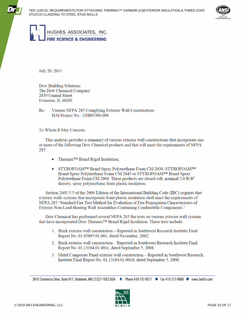
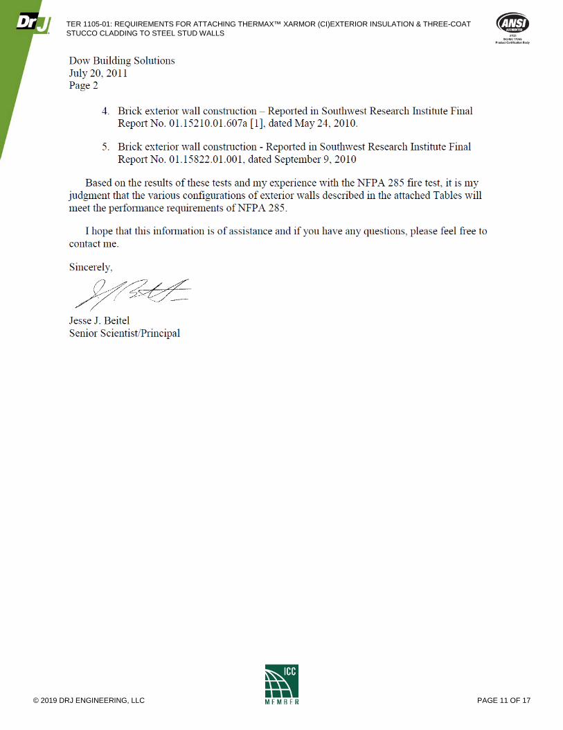
agency.7 Fire Code Compliance with THERMAX™ XARMOR (ci) Exterior Insulation and Three-Coat Stucco Exterior Wall
Covering 12.3.1 THERMAX™ XARMOR (ci) Exterior Insulation with three-coat stucco constructed in accordance with this
TER satisfies requirements for control of exterior flame spread as evaluated in accordance with the NFPA 285 test method. The following engineering letter presents the fire test data, engineering analysis, and code compliant construction recommendations.
7 Performance Test Report / ASTM E331-00 Test Report, Report No. 01-46081.01, prepared by Architectural Testing, Inc. for The Dow Chemical Company; February 12, 2004.
TER 1105-01: REQUIREMENTS FOR ATTACHING THERMAX™ XARMOR (CI)EXTERIOR INSULATION & THREE-COAT STUCCO CLADDING TO STEEL STUD WALLS
© 2019 DRJ ENGINEERING, LLC PAGE 10 OF 17
TER 1105-01: REQUIREMENTS FOR ATTACHING THERMAX™ XARMOR (CI)EXTERIOR INSULATION & THREE-COAT STUCCO CLADDING TO STEEL STUD WALLS
© 2019 DRJ ENGINEERING, LLC PAGE 11 OF 17
TER 1105-01: REQUIREMENTS FOR ATTACHING THERMAX™ XARMOR (CI)EXTERIOR INSULATION & THREE-COAT STUCCO CLADDING TO STEEL STUD WALLS
© 2019 DRJ ENGINEERING, LLC PAGE 12 OF 17
TER 1105-01: REQUIREMENTS FOR ATTACHING THERMAX™ XARMOR (CI)EXTERIOR INSULATION & THREE-COAT STUCCO CLADDING TO STEEL STUD WALLS
© 2019 DRJ ENGINEERING, LLC PAGE 13 OF 17
TER 1105-01: REQUIREMENTS FOR ATTACHING THERMAX™ XARMOR (CI)EXTERIOR INSULATION & THREE-COAT STUCCO CLADDING TO STEEL STUD WALLS
© 2019 DRJ ENGINEERING, LLC PAGE 14 OF 17
TER 1105-01: REQUIREMENTS FOR ATTACHING THERMAX™ XARMOR (CI)EXTERIOR INSULATION & THREE-COAT STUCCO CLADDING TO STEEL STUD WALLS
© 2019 DRJ ENGINEERING, LLC PAGE 15 OF 17
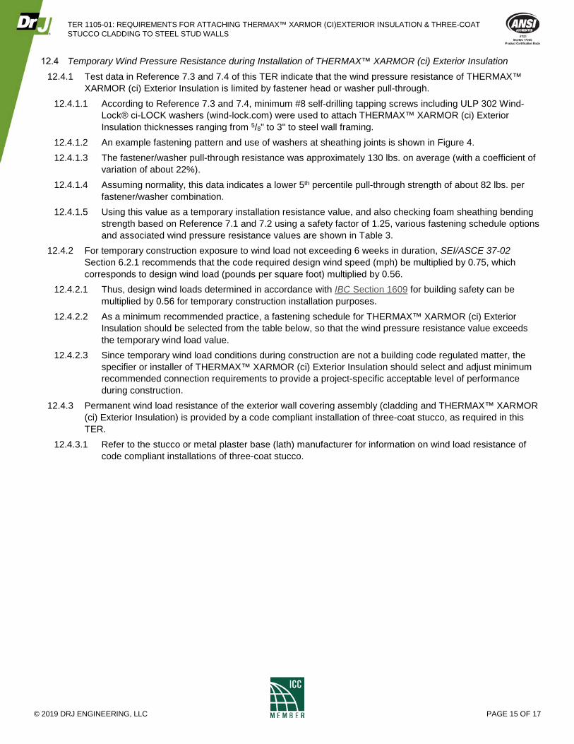
Temporary Wind Pressure Resistance during Installation of THERMAX™ XARMOR (ci) Exterior Insulation 12.4.1 Test data in Reference 7.3 and 7.4 of this TER indicate that the wind pressure resistance of THERMAX™
XARMOR (ci) Exterior Insulation is limited by fastener head or washer pull-through. 12.4.1.1 According to Reference 7.3 and 7.4, minimum #8 self-drilling tapping screws including ULP 302 Wind-
Lock® ci-LOCK washers (wind-lock.com) were used to attach THERMAX™ XARMOR (ci) Exterior Insulation thicknesses ranging from 5/8" to 3" to steel wall framing.
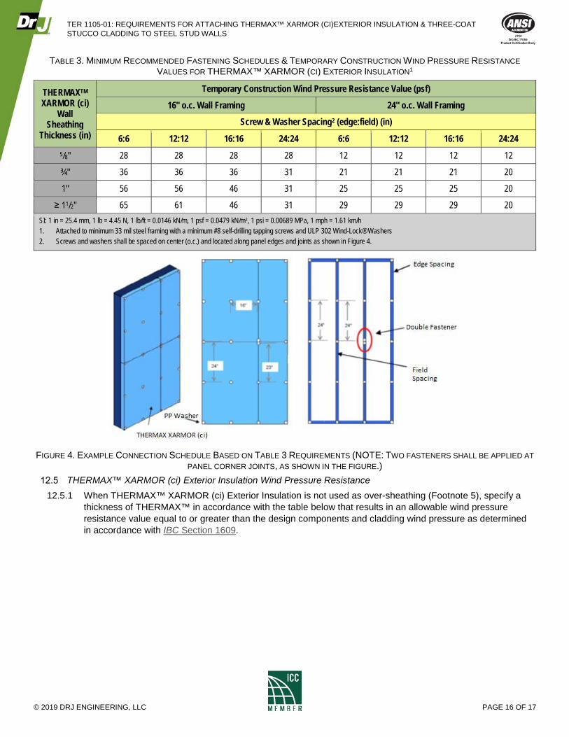
12.4.1.2 An example fastening pattern and use of washers at sheathing joints is shown in Figure 4. 12.4.1.3 The fastener/washer pull-through resistance was approximately 130 lbs. on average (with a coefficient of
variation of about 22%). 12.4.1.4 Assuming normality, this data indicates a lower 5th percentile pull-through strength of about 82 lbs. per
fastener/washer combination. 12.4.1.5 Using this value as a temporary installation resistance value, and also checking foam sheathing bending
strength based on Reference 7.1 and 7.2 using a safety factor of 1.25, various fastening schedule options and associated wind pressure resistance values are shown in Table 3.
12.4.2 For temporary construction exposure to wind load not exceeding 6 weeks in duration, SEI/ASCE 37-02 Section 6.2.1 recommends that the code required design wind speed (mph) be multiplied by 0.75, which corresponds to design wind load (pounds per square foot) multiplied by 0.56.
12.4.2.1 Thus, design wind loads determined in accordance with IBC Section 1609 for building safety can be multiplied by 0.56 for temporary construction installation purposes.
12.4.2.2 As a minimum recommended practice, a fastening schedule for THERMAX™ XARMOR (ci) Exterior Insulation should be selected from the table below, so that the wind pressure resistance value exceeds the temporary wind load value.
12.4.2.3 Since temporary wind load conditions during construction are not a building code regulated matter, the specifier or installer of THERMAX™ XARMOR (ci) Exterior Insulation should select and adjust minimum recommended connection requirements to provide a project-specific acceptable level of performance during construction.
12.4.3 Permanent wind load resistance of the exterior wall covering assembly (cladding and THERMAX™ XARMOR (ci) Exterior Insulation) is provided by a code compliant installation of three-coat stucco, as required in this TER.
12.4.3.1 Refer to the stucco or metal plaster base (lath) manufacturer for information on wind load resistance of code compliant installations of three-coat stucco.
TER 1105-01: REQUIREMENTS FOR ATTACHING THERMAX™ XARMOR (CI)EXTERIOR INSULATION & THREE-COAT STUCCO CLADDING TO STEEL STUD WALLS
© 2019 DRJ ENGINEERING, LLC PAGE 16 OF 17
TABLE 3. MINIMUM RECOMMENDED FASTENING SCHEDULES & TEMPORARY CONSTRUCTION WIND PRESSURE RESISTANCE VALUES FOR THERMAX™ XARMOR (CI) EXTERIOR INSULATION1
THERMAXTM XARMOR (ci)
Wall Sheathing
Thickness (in)
Temporary Construction Wind Pressure Resistance Value (psf)
16" o.c. Wall Framing 24" o.c. Wall Framing
Screw & Washer Spacing2 (edge:field) (in)
6:6 12:12 16:16 24:24 6:6 12:12 16:16 24:24 5/8" 28 28 28 28 12 12 12 12
¾" 36 36 36 31 21 21 21 20
1" 56 56 46 31 25 25 25 20
≥ 11/2" 65 61 46 31 29 29 29 20 SI: 1 in = 25.4 mm, 1 lb = 4.45 N, 1 lb/ft = 0.0146 kN/m, 1 psf = 0.0479 kN/m2, 1 psi = 0.00689 MPa, 1 mph = 1.61 km/h 1. Attached to minimum 33 mil steel framing with a minimum #8 self-drilling tapping screws and ULP 302 Wind-Lock® Washers 2. Screws and washers shall be spaced on center (o.c.) and located along panel edges and joints as shown in Figure 4.
FIGURE 4. EXAMPLE CONNECTION SCHEDULE BASED ON TABLE 3 REQUIREMENTS (NOTE: TWO FASTENERS SHALL BE APPLIED AT
PANEL CORNER JOINTS, AS SHOWN IN THE FIGURE.) THERMAX™ XARMOR (ci) Exterior Insulation Wind Pressure Resistance
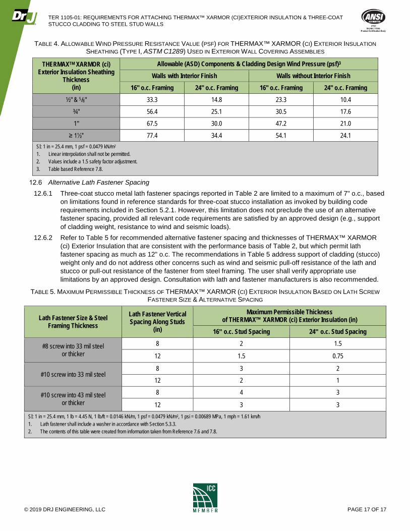
12.5.1 When THERMAX™ XARMOR (ci) Exterior Insulation is not used as over-sheathing (Footnote 5), specify a thickness of THERMAX™ in accordance with the table below that results in an allowable wind pressure resistance value equal to or greater than the design components and cladding wind pressure as determined in accordance with IBC Section 1609.
TER 1105-01: REQUIREMENTS FOR ATTACHING THERMAX™ XARMOR (CI)EXTERIOR INSULATION & THREE-COAT STUCCO CLADDING TO STEEL STUD WALLS
© 2019 DRJ ENGINEERING, LLC PAGE 17 OF 17
TABLE 4. ALLOWABLE WIND PRESSURE RESISTANCE VALUE (PSF) FOR THERMAX™ XARMOR (CI) EXTERIOR INSULATION SHEATHING (TYPE I, ASTM C1289) USED IN EXTERIOR WALL COVERING ASSEMBLIES
THERMAXTM XARMOR (ci) Exterior Insulation Sheathing
Thickness (in)
Allowable (ASD) Components & Cladding Design Wind Pressure (psf)3
Walls with Interior Finish Walls without Interior Finish
16" o.c. Framing 24" o.c. Framing 16" o.c. Framing 24" o.c. Framing
½" & 5/8" 33.3 14.8 23.3 10.4
¾" 56.4 25.1 30.5 17.6
1" 67.5 30.0 47.2 21.0
≥ 1½" 77.4 34.4 54.1 24.1 SI: 1 in = 25.4 mm, 1 psf = 0.0479 kN/m2 1. Linear interpolation shall not be permitted. 2. Values include a 1.5 safety factor adjustment. 3. Table based Reference 7.8.
Alternative Lath Fastener Spacing 12.6.1 Three-coat stucco metal lath fastener spacings reported in Table 2 are limited to a maximum of 7" o.c., based
on limitations found in reference standards for three-coat stucco installation as invoked by building code requirements included in Section 5.2.1. However, this limitation does not preclude the use of an alternative fastener spacing, provided all relevant code requirements are satisfied by an approved design (e.g., support of cladding weight, resistance to wind and seismic loads).
12.6.2 Refer to Table 5 for recommended alternative fastener spacing and thicknesses of THERMAX™ XARMOR (ci) Exterior Insulation that are consistent with the performance basis of Table 2, but which permit lath fastener spacing as much as 12" o.c. The recommendations in Table 5 address support of cladding (stucco) weight only and do not address other concerns such as wind and seismic pull-off resistance of the lath and stucco or pull-out resistance of the fastener from steel framing. The user shall verify appropriate use limitations by an approved design. Consultation with lath and fastener manufacturers is also recommended.
TABLE 5. MAXIMUM PERMISSIBLE THICKNESS OF THERMAX™ XARMOR (CI) EXTERIOR INSULATION BASED ON LATH SCREW FASTENER SIZE & ALTERNATIVE SPACING
Lath Fastener Size & Steel Framing Thickness
Lath Fastener Vertical Spacing Along Studs
(in)
Maximum Permissible Thickness of THERMAX™ XARMOR (ci) Exterior Insulation (in)
16" o.c. Stud Spacing 24" o.c. Stud Spacing
#8 screw into 33 mil steel or thicker
8 2 1.5
12 1.5 0.75
#10 screw into 33 mil steel 8 3 2
12 2 1
#10 screw into 43 mil steel or thicker
8 4 3
12 3 3 SI: 1 in = 25.4 mm, 1 lb = 4.45 N, 1 lb/ft = 0.0146 kN/m, 1 psf = 0.0479 kN/m2, 1 psi = 0.00689 MPa, 1 mph = 1.61 km/h 1. Lath fastener shall include a washer in accordance with Section 5.3.3. 2. The contents of this table were created from information taken from Reference 7.6 and 7.8.