Embed Size (px)
Citation preview

IOSR Journal of Electrical and Electronics Engineering (IOSR-JEEE)
e-ISSN: 2278-1676, p-ISSN: 2320-3331, Volume 16, Issue 3 Ser. II (May – June 2021), PP 37-57 www.iosrjournals.org
DOI: 10.9790/1676-1603023757 www.iosrjournals.org 37 | Page
Technical Evaluation for connections of Non-standardVector
Groups (Dy5/Dy11 and Yyn) in Nigerian 33/11kV Network
Paul I. Audu PAUMA ENGINEERING CONSULTANTS, Kaduna Nigeria.
Abstract: Evolving from the era of British Standards Specifications to multiplicity of standards, Electricity
Industry in Nigeria has witnessed very negative transformations. Efforts of engineers to address the matter over
the years has not yielded any dividend because control of equipment specifications for the electricity industry is
beyond the control of the engineering community. In this write-up, we have tried as much as possible to take an
in-dept look at Transformer Vector Group abuse in Nigeria and its attendant consequences on the entire Power
System. Efforts have also been made to address multiple cases of transformers introduced into the system with a
view to correct the power system anomalies.
Background: One of the key areas of the supply industry that needs conformance to required standard include
the ever-elusive power system stability and power quality, and the matter of Transformer Vector Group may be
part of the problems. Efforts by the Nigerian Electricity Management Services Agency (NEMSA) in recent years
to address this has not really yielded positive result because engineers themselves are still battling with the
matter of power availability to think of and understanding other critical areas of Power System Engineering. We are still trying to understand this controversy over transformer vector group and its effect on the power system,
denying NEMSA the much-needed voice for this crusade.
Materials and Methods: We have endeavoured in this article to take a close look at the Nigerian National Grid
in terms of the Distribution Sub-sector and Network integration with a view to addressing issues that can create
instability in the 132/33kV Sub-transmission system. To achieve this the problems of the Nigerian National Grid
is reviewed through standard Network Configuration requirement from Generation through Transmission to
Distribution Electricity Networks, evaluating the attendant issues, analysing transformer Vector Group abuse
and addressing the technical implications.
Results: The investigation revealed some instability introduced into the Electric Power System with the
installation of non-standard transformers and these include unavoidable phase-shifts thatcause error when
trying to determine the true power consumption, results in deviation of actual power-factor and Real Power
delivered,Negative Power Factor that produces reverse power flow in the system and possible over-voltages, the effects of the harmonic currents that results in additional copper losses, Increased core losses, Increased
electro-magnetic interference, as well as Resonance between winding reactance and feeder capacitance.The
conclusive results show about 35,138.88Kwhr energy deficit per month and 421,666.56Kwhr per year for a
500KVA transformer operating at 240 phase-shift due to introduction of Dy11 Power Transformer in the
33/11kV Network.
Conclusion: It is concluded that outright ban of such installation is the basic solution to this problem and in
cases that are already in the system, internal or external vector re-configuration is recommended.
KeyWords: Vector Group, Phase Shift, Dy1, Dy5, Dy11, Yyn, Power Transformer, Distribution
Transformer
---------------------------------------------------------------------------------------------------------------------------------------
Date of Submission: 06-06-2021 Date of Acceptance: 20-06-2021
---------------------------------------------------------------------------------------------------------------------------------------
I. Introduction In electrical power system engineering, vector group is the method for characterizing the high
voltage (H.V) and low voltage (L.V) winding connections of three phase transformers, as approved by
international electro technical commission (IEC) and other international standards. According to IEC
60076-1 coding technique, vector groups are represented by letters for each set of winding and the phasor
related with (H.V) is taken as reference with capital letters and is stationary at 12 0’ clock, while (L.V) side
vector is rotating with the reference vector using lowercase letters, to represent phase displacement between
two sides of transformers.
In a typical power system network like Nigerian National Grid, we will observe quite a number of
forward and backward 300 phase shifts as shown in figure 1. The reason for the forward and backward
300shift introduced by delta/star or star/delta transformer is that delta connection provides a path for the
third order harmonic current in Generator Step-up transformers andhence no distortion because of it.For

Technical Evaluation for connections of Non-standard Vector Groups ..
DOI: 10.9790/1676-1603023757 www.iosrjournals.org 38 | Page
Power export/import transformers used for Transmission purpose, Transformer star-star connection may be
preferred since this avoids a grounding transformer on generator side and perhaps save on neutral
insulation. Three phase power transformers in transmission may have Y-Delta windings because of economics
(Y on HV side to have less insulation requirements per winding and Delta, on LV-high current side for
copper savings per phase) or may be used to restrict zero sequence current from Transmission line under
fault penetrating into generator circuit. These configurations produce phase shift of 30 degree between HV
and LV side before finally being delivered to the end user who must receive an almost lossless replica of
power generated at the source. Since there are several voltage transformations from the source to the end
user in a typical large grid network, there will be a number of forward and backward 300 phase-shifts as
indicated.
II. The Problems Of Nigerian National Grid In an effort to eliminate harmonics in the system and maintain the power supply integrity replica
of source of generation in the Nigerian Power System, deliberate phase-shift arrangement is made right
from generation to distribution levels as shown in figure 1 below. This is because it is easier to correct a
phase-shift than dealing with harmonics in the power system. For instance, a close look at the diagram
shows several clockwise and anti-clockwise movements in the vector configurations in an effort to
maintain true image of the source. However, it has been observed that several varying vector group
configurations at variance with these standard requirements have been introduced into the system
nationwide and we need to take a close look at the implications and proffer possible solution. This is the
object of this write-up.
Figure 1: Vector-group Configuration in Nigerian National Grid
This is the basis for Nigerian Electricity Supply and Installation Standards Rules (NESIS 2015 2.3.4.1 and
4.2.4.1) which give detailed specifications on how these transformations can be achieved.
If these regulations are strictly adhered to, it will result in the phasor relationship between the generation and
distribution subsectors of the power system illustrated in the diagrams of figure 2 below.

Technical Evaluation for connections of Non-standard Vector Groups ..
DOI: 10.9790/1676-1603023757 www.iosrjournals.org 39 | Page
Figure 2: Voltage Wave-form based on the Vector-group Configurations
III. Problem Evaluation Several issues of Vector Group abuse in the Nigerian 33/11kV Sub-transmission Network have been
discovered of recent. These range from installation of 33/11kV Dy11 Power transformers to Dyn5 11/0.415
Distribution Transformers in place Dy11 as well as 11/0.415 Yyn0 in the 11kV network. We will address these cases one after the other.
3.1 Dy11 Transformers in the 33/11kV Network
It is a well-known fact that so many power transformers of the Dy11 configuration have been
introduced into the 33/11kV System by quite a number of establishments without due consideration to attendant
technical implications on the National Grid. Application of Dy11 in the 33/11kV system of the National Grid
could create a problem in the system, given the Vector Configurations from Generation down to Transmission
and subsequently to Distribution levels. Some of the problems introduced include:
1. Unwanted Circulating Currents in the system, Out-of-step voltages could adversely affect system
operation and stability, Phase-angle displacement conditions may be injurious to the power system in times of faults and critical loads.
2. Differential Current Control: There is the introduction of abnormal phase angle displacement that
could cause problem to the entire Power System. In this regard, the combination of the Power
Transformer in series with the Distribution Transformer where additional 600 phase-shift has been
introduced shall be considered as technical insertion of Phase-shifting Transformer in the Power
System between Transmission and end users. This will create serious problems in the Power System
Configurations.
There are Particular differential currents arising from this type of special transformers in backup
current circulation.
3. Accuracy of Metering or Monitoring the amount of Energy in the circuit in Amplitude and Phase-angle due to additional phase angle difference or phase-shift effect in the connection of the relevant
Current Transformers. These include;
Actual Phase Angle Shift () introduced by the transformers
Star-point location of the Metering Current Transformer
Technical Evaluation for connections of Non-standard Vector Groups ..
DOI: 10.9790/1676-1603023757 www.iosrjournals.org 40 | Page
4. Unbalance System Considerations involving possibilities of voltage and current unbalances that can
possibly give rise to harmonics. Any deviation in voltage and current waveform from perfect
sinusoidal, in terms of magnitude or phase shift is termed as unbalance. 5. Phase-shift anomalies arising in the system using the impact of the Delta and the Star connected CTs
placed respectively on both the Star and the Delta sides of the transformer as follows:
There will be magnitude matching and differential summation problems.
Zero sequence currents (Delta connected CTs) may exist from the grounded Star winding in
conflict with the zero sequence free currents measured from the Star connected CTs on the Delta
winding of the transformer.
Additional phase shift may be introduced by the CTs from both sides of the transformer in Star,
such that the currents introduced to the relay terminals will have different transformer phase
values.
3.2 Dy5 Transformers in the 11/0.415kV Network The Dyn5 and Dyn11 transformer have the same output voltages and phase sequence and the same neutral
connection to the secondary star point. The main difference is that the output voltages relative to the neutral are
all reversed if we connect one of each transformer to the same supply. When one phase is at maximum positive
with respect to neutral on the Dyn5, at the same instant that phase will be at maximum negative on the Dyn11.
3.3 Implications of the Vector Group Star-star 3-phase Yyn, 11/0.415KV Transformer connection There is this case of Yyn, 11/0.415kV Traction Transformers installed along Abuja-Kaduna rail route for the
purpose of Railway Communication Systems and Rail-line services by the Chinese Civil Engineering Company
for use by Electric Traction. This is illustrated in figure 9 interfaced with 132/33kV source:
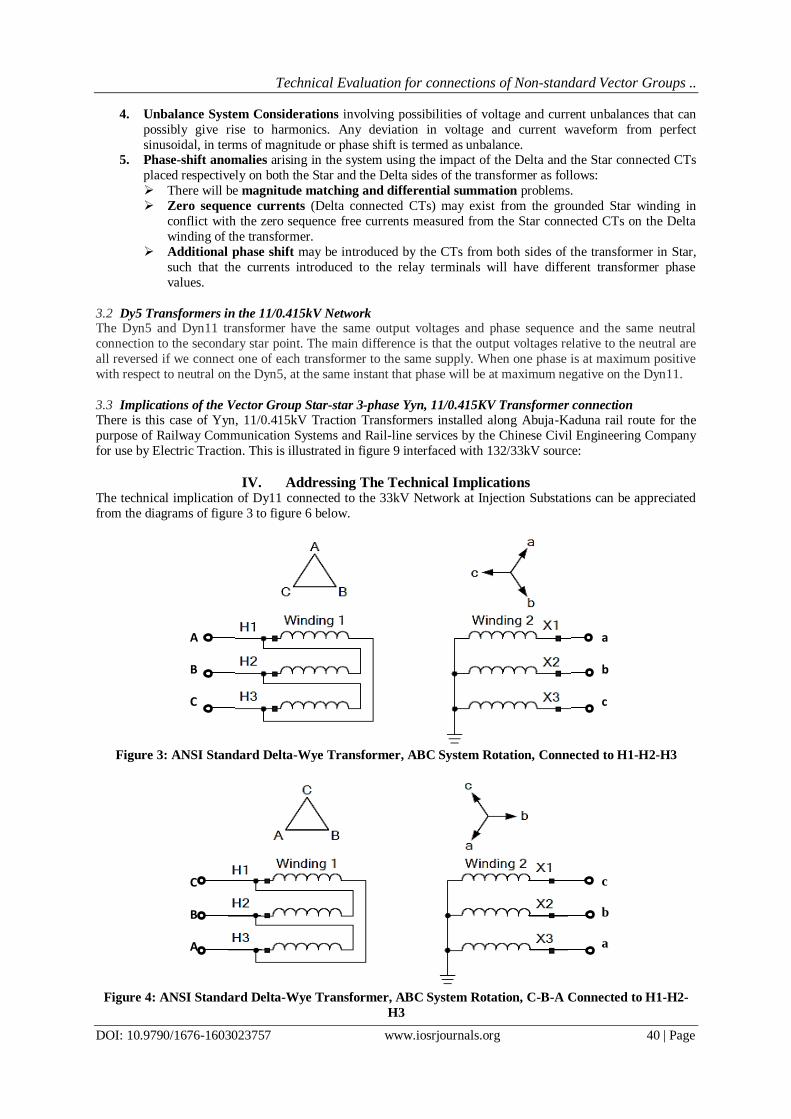
IV. Addressing The Technical Implications The technical implication of Dy11 connected to the 33kV Network at Injection Substations can be appreciated
from the diagrams of figure 3 to figure 6 below.
Figure 3: ANSI Standard Delta-Wye Transformer, ABC System Rotation, Connected to H1-H2-H3
Figure 4: ANSI Standard Delta-Wye Transformer, ABC System Rotation, C-B-A Connected to H1-H2-
H3
C
B
A
c
b
a
A
B
C
a
b
c

Technical Evaluation for connections of Non-standard Vector Groups ..
DOI: 10.9790/1676-1603023757 www.iosrjournals.org 41 | Page
Figure 5: Comparison of Dy1 and Dy11 Vector-group Configuration connection on the 33/11kV Power
System.
The first instance is the polarity convention shown in figure 3 In transformer phase rotation, connection
of Polarity and Non-polarity winding terminals play very important roles in phase relationship and phase
rotation. For the transformer nameplate drawing in Figure 3, if ABC phase rotation is assumed, the high-side
currents will lead the associated low-side currents by 30 degrees. This is a DABY connection because the
polarity of A-phase is connected to the non-polarity of B-phase.
The transformer nameplate shown in Figure 4 is exactly like the nameplate in figure 6, but now the
system phase connections to the H1, H2, and H3 terminals have changed. Notice that A-phase is now connected
to H3 and C-phase is now connected to H1. This is a DACY connection because the polarity of A-phase is
connected to the non-polarity of C-phase. The corresponding winding configurations are illustrated in figure 4 the corresponding phasor diagram
of Dy11, 33/11kV Power transformer supplying Dy11, 11/0.415kV Distribution Transformer is also illustrated
in figure 5
Figure 6: Voltage wave-form based on the Vector-group for Dy11 on the 33/11kV Power System

Technical Evaluation for connections of Non-standard Vector Groups ..
DOI: 10.9790/1676-1603023757 www.iosrjournals.org 42 | Page
Any phase angle difference between the two waveforms is known as phase shift and causes an error when
trying to determine the true power consumption. However, a phase shift of the current wave form from the
input of a current transformer to the output is a common problem.
In terms of power flow, when metering or monitoring the amount of power dissipated in a circuit it is important
to have an accurate measurement of each of the two contributing waveforms, voltage and current. Accuracy is
not only necessary for amplitude of the two waveforms, but also the phase relationship between the waveforms
must be considered. Any phase angle difference between the two waveforms is known as phase shift and causes
an error when trying to determine the true power consumption. When metering or monitoring, the use of
components that add minimal or at least predictable amounts to the phase shift are important to allow for
accurate results.
4.1 Replacement of Dy11 with Dy5 One of the common problems that confront our Distribution Network is the installation of Dy5 in place of Dy11. The phase Rotation diagram in figure 11 below gives the illustration of the implication.
With regards to theory, there are no special advantages of Dyn11 over Dyn5. In isolated applications there is no
advantage or disadvantage by using Dy5 or Dy11. If however we wish to interconnect the secondary sides of
different Dyn transformers or use them in redundancy to feed the same secondary loads, we must have
compatible transformers.
Figure 11: Phasor relationship between Dy11 and Dy5 with reference to Fundamental Phasor at source
4.2 Implications of the Vector Group Star-star 3-phase Yyn, 11/0.415KV Transformer connection The Nigerian Electricity Management Services Agency (NEMSA) tried to evaluate the implication of this type
of installation on our 33/11/0.415kV Distribution System. The first thing of note here is that the Primary
winding has a “FLOATING NEUTRAL” not connected to earth. It was suspected that this situation could result
to generation of Harmonics in the System particularly unbalanced load or unsymmetrical fault conditions.

Technical Evaluation for connections of Non-standard Vector Groups ..
DOI: 10.9790/1676-1603023757 www.iosrjournals.org 43 | Page
Figure 15: Connection Diagram for Yyn33/0.415kV DistributionTransformer on 132/33kV Network.
V. Problem Analysis It is a well-known fact that for standard power/distribution transformer with vector group Dy (i.e.
Delta-star connection) the phase to ground fault on the LV side (i.e. star side) is manifested as phase-to-phase
fault on the transformer HV side (i.e. delta side). Question can be raised how different type of faults will be seen
across the power transformer with variable phase angle shift? Our case is shown in figure 7.
The knowledge of the fault current distribution is most important for transformer and system backup
protection such as distance protection, over-current protection and earth-fault protection. Figure 7a is a typical
connection diagram, and 7b is current distribution for single-phase to earth fault. The fault current distribution
for phase-to-phase fault is also shown in figure 7c.
Figure 7a: Normal Dy1/Dy11 interconnection Figure 7b: Single phase to ground current flow
a b c n
A B C
11/0.415KV
a b c n
A B C
33/11KV
A2 A1 B2 B1 C2 C1
a2 b1 b2 c1 c2
a b c n
A B C
b c n
A B C
A2 A1 B2 B1 C2 C1
a1 a2 b1 b2 c1 c2
a b c n
A B C
11/0.415KV Dy11
a b c n
A B C
33/11KV, Dy11 A2 A1 B2 B1 C2 C1
a1 a2 b1 b2 c1 c2

Technical Evaluation for connections of Non-standard Vector Groups ..
DOI: 10.9790/1676-1603023757 www.iosrjournals.org 44 | Page
Figure 7c: Fault current flow with phase-to-phase fault
Figure 7: Typical Current Distribution in Dyn11 Power & Distribution Transformers.
It can be seen from figure 7b above that even though the line-to-line voltage ratio is N/1, the actual turns ratio is
of the range given by6:
N = N3
(1/3) 1
When a phase to earth/neutral fault occurs in low voltage side of the distribution transformer, the amount of the
short circuit current is shown in the following formula:
The equivalent short circuit current on the HV side of the transformer is given by:
It is clear from the above formula that for phase to earth fault, the fault current on the LV side must be
multiplied by (1/3) if we want to know the referred current on the HV side. This will circulate as phase-to-phase current on the HV and LV side of our Power Transformer.
5.1 Differential Current Considerations From differential current point of view, we shall consider the classic and typical voltage and current
definitions used for a three-phase, two-winding Power Transformer shown in figure 8, and also take our power
transformer together with the downstream distribution transformer as a case of two-winding transformer with
arbitrary phase angle shift Ɵ (+600).
a
b
c
n
A
B
C
11/0.415KV
a
b
c
n
A
B
C
33/11KV
A2
A1
B2
B1
C2
C1
a1
a2
b1
b2
c1
c2

Technical Evaluation for connections of Non-standard Vector Groups ..
DOI: 10.9790/1676-1603023757 www.iosrjournals.org 45 | Page
Figure 8: Typical voltage and current reference direction for a transformer
10
The standard three-phase power transformers introduce a fixed phase angle shift Θ of n*30o (n=0, 1, 2, …, 11)
between its winding 1 and winding 2 side no-load voltagesto achieve the standard 300 phase shift, as shown in
Figure 910 below for the cascaded Dy11.
Figure 9: Phasor diagram for individual phase no-load voltages for our cascaded Dy11
If one now considers only the case of two-winding transformer with arbitrary phase angle shift Ɵ, as shown in
Figure 9 with additional assumption that during through-faults (i.e. external faults) all three differential currents
will be zero in all phases, then the equation can be derived to calculate the S-side individual phase currents I_S1,
I_S2 & I_S3 from the L side phase currents I_L1, I_L2 & I_L3 in primary amperes.1
In this consideration current magnitude diagrams shall be provided for -60° < Ɵ < 60° which is the most
commonly used range for the phase shift angle of special power transformers in practical installations.
5.2 Unbalance System Considerations There are possibilities of voltage and current unbalances that can possibly give rise to harmonics. Any deviation
in voltage and current waveform from perfect sinusoidal, in terms of magnitude or phase shift is termed as
unbalance.
In ideal conditions such as with only linear loads connected to the system, the phases of power supply are 120
degree apart in terms of phase angle and magnitude of their peaks should be same. On distribution level, the
load imperfections cause current unbalance which travel to transformer and cause unbalance in the three-phase voltage. Even minor unbalance in the voltage at transformer level disturbs the current waveform significantly on
all the loads connected to it. Not only in the distribution side but through the transformer, voltage unbalances
disturb the high voltage power system as well.
5.3 Dy5 Transformers in the 11/0.415kV Network Let us take a look at the vector groups for a Dyn1, Dyn5 and Dyn11 when excited by counterclockwise, positive
sequence, phase rotation ABC as shown in figure 10 below11.

Technical Evaluation for connections of Non-standard Vector Groups ..
DOI: 10.9790/1676-1603023757 www.iosrjournals.org 46 | Page
Figure 10: Phasor Diagrams of Positive Sequence Phase Rotation of Dy1, Dy5 and Dy1111
Note that the vector groups for the Dyn1 and Dyn5 seem to be in phase with each other but the phase rotation of
the bushings do not match, with the Dyn5 lagging the Dyn1 by 1200. Also note that the output vector group of a
Dyn1 also lags a Dyn11 by 60º, and the difference in output between the Dyn11 and Dny5 and is 180 degrees.
When the phase rotation of the excitation source is reversed from ABC to ACB, the vector groups are mirrored
as shown in figure 11 below (a phase rotation meter connected ABC would rotate in the negative direction; or if
connected ACB, would rotate in the positive direction):
Figure 11: Phasor Diagrams of Counterclockwise Phase Rotation of the VectorGroups
11
So, there are the implications of matching the vector groups of a Dyn11 and Dyn5. Given a Dyn11 with positive
sequence phase rotation ABC, a Dyn5 will have the same vector group if the phase sequence is reversed.
Correction can only be obtained when the HV and LV terminals are matched in certain configuration.
Phase sequence and phase rotation is critical to certain loads.
If we use Dy1 Transformer as the source to a Dy5 Distribution Transformer, then the -300lag of generating side (Dy1) is further lagged by -1500 Lag at Receiving side (Dy5) so Total phase difference respect to source is 180
deg (–30 + –150 = –180). This is illustrated in figure 12 below:

Technical Evaluation for connections of Non-standard Vector Groups ..
DOI: 10.9790/1676-1603023757 www.iosrjournals.org 47 | Page
Figure 12: The implication of feeding a Dy5 transformer from a standard 33/11kV Dy1 Substation.
The practical implication is that if we label the phases on HV clockwise as R- Y-B from left to right, then the
LV side must be counterclockwise or Right to Left.
For a single transformer feeding an isolated load, this phase reversal will be of no consequence, long as the
output voltages and phase sequences are correct. The problems arise if we are using two transformers to supply
one load. For example, if two transformers are used to supply the same premises, one duty and one standby,
with a manual or automatic changeover switch on the secondaries. If the switch is operated while both
transformers are live, the load voltages will (almost) instantly reverse polarity. Some loads will not like this and
may trip their protection.Another example is two identical transformers running in parallel. These must have the same vector grouping otherwise they will short circuit the input supply when the parallel connection is made.
By doing some unconventional connections externally on one side of the Transformer, an internal connected
Dyn1 transformer can be changed either to a Dyn5(-150°) or Dyn9(+90°) connection. This will be discussed
later.
5.4 The Yyn Transformer problem The first consideration centred on a possible distortion in the Power Supply that can create problems for the
source. The Protection System cannot be guaranteed because of distortion in Phase-angles.
The direct consequences of this are as follows: a. The effects of the harmonic currents are:
1. Additional copper losses due to harmonic currents
2. Increased core losses
3. Increased electro-magnetic interference with communication circuits.
b. On the other hand, the harmonic voltages of the transformer can cause:
1. Increased dielectric stress on insulation
2. Electrostatic interference with communication and other control circuits.
3. Resonance between winding reactance and feeder capacitance.
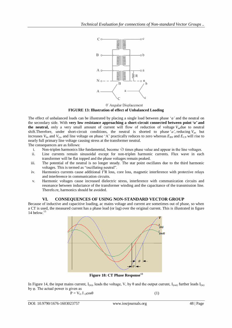
Because of ungrounded neutral, and presence of third-harmonic voltages,if we place a single load between phase
‘a’, an unbalanced load to the neutral, the neutral point shifts thereby making the three line-to-neutral voltages
unequal. Figure 13 illustrates a bank of three transformers connected in Y on both the primary and the secondary sides as shown.
Technical Evaluation for connections of Non-standard Vector Groups ..
DOI: 10.9790/1676-1603023757 www.iosrjournals.org 48 | Page
The effect of unbalanced loads can be illustrated by placing a single load between phase ‘a’ and the neutral on
the secondary side. With very low resistance approaching a short-circuit connected between point ‘a’ and
the neutral, only a very small amount of current will flow of reduction of voltage Vandue to neutral
shift.Therefore, under short-circuit conditions, the neutral is shorted to phase ‘a’, reducing Van but
increases Vbn and Vcn, and line voltage on phase ‘A’ practically reduces to zero whereas EBN and ECN will rise to nearly full primary line voltage causing stress at the transformer neutral.
The consequences are as follows:
i. Non-triplen harmonics like fundamental, become √3 times phase value and appear in the line voltages.
ii. Line currents remain sinusoidal except for non-triplen harmonic currents. Flux wave in each
transformer will be flat topped and the phase voltages remain peaked.
iii. The potential of the neutral is no longer steady. The star point oscillates due to the third harmonic
voltages. This is termed as “oscillating neutral”.
iv. Harmonics currents cause additional I2R loss, core loss, magnetic interference with protective relays
and interference in communication circuits.
v. Harmonic voltages cause increased dielectric stress, interference with communication circuits and
resonance between inductance of the transformer winding and the capacitance of the transmission line.
Therefo.re, harmonics should be avoided.
VI. CONSEQUENCES OF USING NON-STANDARD VECTOR GROUP Because of inductive and capacitive loading, ac mains voltage and current are sometimes out of phase, so when
a CT is used, the measured current has a phase lead (or lag) over the original current. This is illustrated in figure
14 below.13
Figure 18: CT Phase Response
13
In Figure 14, the input mains current, I(in), leads the voltage, V, by θ and the output current, I(out) further leads I(in)
by φ. The actual power is given as
P = VO I Ocosθ (1)
FIGURE 13: Illustration of effect of Unbalanced Loading

Technical Evaluation for connections of Non-standard Vector Groups ..
DOI: 10.9790/1676-1603023757 www.iosrjournals.org 49 | Page
where VO is the maximum ac input voltage, IO is the maximum ac input current, and cosθ is the power factor.13
The measured power is represented as; P = K(V)V’O K(I) I’Ocos(θ + φ) ′ (2)
where K(V) is the scale-down factor for voltage (VO = K(V)V’O), K(I) is the scale-down factor for current (IO =
K(I) I′O), and cos(θ +φ) is the measured power factor.13
The measured error is given by;
(3) The error is a nonlinear function of the power factor. As the power factor decreases, the error becomes
significant. For example, with a power factor of 0.5 and a phase shift of 1°, the error is an unacceptable 3%.13
6.1 Power and Energy Requirements It must be noted that at this utilisation output point, the output voltage is expected to be a replica of and in phase
with the fundamental potential at the source of supply. If phase shift is sustained or expanded in the power
transformer, it must translate to the current transformers providing the actual power and fault status of the
system. Introducing current phase shift due to Power Factor, we have the diagram of figure 15.
It can be demonstrated that Real Power consumption become lesser than Apparent Power as Power Factor
gets affected because, any shift in the current waveform from the voltage waveform creates a power factor lower
than normal. Power factor (PF) is theratio between the true power (Watts) dissipated by the load and the
apparent power (VoltAmps) that must be generated to satisfy the load. Details are discussed in the technical
implications section below.
Figure 15: Sustenance of Phase shift due to Power Factor using Standard Vector Group
For delta/star (∆/Y), or star/delta (Y/∆) transformer windings connections there is a phase shift in a balanced
voltage and currents of typically ± 300 depending on transformer connections 12. As presented in figure 2, with a
transformer -300 phase shift lagging (Dy1), a transformer with +300 will return the waveform back to and in phase with the original generated value.
In the example shown in figure 15 above, if we take into consideration a three-phase 500KVA, 11/0.415kV
Distribution Transformer, the rated current at the 415V end is given by:
IO =
= 695.6A

Technical Evaluation for connections of Non-standard Vector Groups ..
DOI: 10.9790/1676-1603023757 www.iosrjournals.org 50 | Page
Where IO = Load Current.
It follows from figure 15 that Real Power delivered is given by;
PO = IOVO cos(/5) = 3*695.6*415*cos(360) = 404,508 KW
Reactive Power, QO = IOVO cos(/5) = 3*695.6*415*sin(360) = 293,892.6 KVAR
Therefore, Apparent Power, SO = = = 500 KVA
In the case of using Dy11 Vector Group at the 33/11kV Injection Substation, the situation translate to the
diagram of figure 16.
Again, if we take into consideration a three-phase 500KVA, 11/0.415kV Distribution Transformer, it follows
from figure 15 that Real Power delivered is given by;
PO = IOVO cos(2/15) = 3*695.6*415*cos(240) = 456,772.73 KW
Reactive Power, QO = IOVO cos(2/15) = 3*695.6*415*sin(240) = 203,368.32 KVAR
Therefore, Apparent Power, SO = = = 500 KVA
Figure 16: The illustration of delivering power using Dy11, 33/11kV Power Transformer.
The implication here is that sustaining the apparent power of 500 KVA requires that more active power
be supplied to the tune of about 13%. That is, Real Power requirement will jump to 91% of apparent power as
against 80% envisaged from the source.
In terms of energy consumed within one month of an average of twenty-eight (28) active days and 672 active hours, the following calculations apply:
Total Energy to be billed based on standard 0.8 Power Factor = 404.51*672 = 271,830.72kwhr
Total Energy released due to wrong Power Factor application = 456.8*672 = 306,969.6Kwhr
Energy Deficit in one month = 306,969.6 – 271,830.72 = 35,138.88Kwhr
This translates to 12*35,138.88 = 421,666.56Kwhr per year.
It accounts for a loss of about one and half month of the year. It could be worse depending on power
availability.
6.2 Measurement Errors in Current Transformers In a complex Phase angle errors, the current transformer introduces a phase shift (or time delay) in the AC
current signal, relative to the actual current. This is commonly measured in degrees and varies from 0.2 degrees
for highly accurate CTs to as high as 6 degrees. At and near unity power factor. At lower power factors, such

Technical Evaluation for connections of Non-standard Vector Groups ..
DOI: 10.9790/1676-1603023757 www.iosrjournals.org 51 | Page
as 0.7 or below (especially below 0.5), even small phase angle errors can cause large errors in the
measured power and energy. In order to correctly apply protection, it is necessary to properly compensate for the phase shift, using current
transformers which monitor current magnitudes and phase relationship on both sides. The delta/star winding
current transformers need to be connected in a way to compensate for a) Current magnitude; b) Phase angle
shift; and c) provide zero sequence current. This is to ensure that the phase shifts created in the currents of the
power transformer are compensated by the CTs. In metering and protection circuits where phase shifts
deviate from original design concept, errors are introduced.
In the case of a lagging current (inductive loads), the CT phase angle error (assuming it is greater than one
degree) will make the power factor and real power values look higher than they actually are, especially for low
power factors. The corrected values will show a lower power factor and lower real power.14
This relationship is evaluated as follows14:
Reported (measured) power factor
Reported (measured) real power
CT phase angle error (leading, degrees)
Apparent power (not affected by CT phase angle errors)
Phase angle between line voltage and current (lagging, degrees), based on reported
PF
Phase angle between line voltage and current with the CT phase error (lagging,
degrees).
Corrected power factor
Corrected real power
Percentage error in reported power
The particular case of the power factors calculated above will be used as an example and proof of errors
for the CTs in the 33/11kV Injection Substation. From figure 20, section… we proceed as follow assuming CT Phase Angle Error of 20:
Assumed Power Factor between line voltage and current, PFR = 0.81 (lagging)
Assumed Real Power, PR = 404.51 KW
CT Phase Angle Error, CT = 20 (leading)
Apparent power, S = PR/ PFR = 404.51/0.81 = 499.4KVA 500KVA
Phase angle between line voltage and current, R = cos-1(0.81) = 360 (lagging) Phase angle between line voltage and current with the CT phase error, is given by;
C = R + CT = (36 + 2) = 380(lagging) Corrected power factor with reference to Dy11 Power Transformer, PFCT = cos(38) = 0.788
Actual Phase angle between line voltage and current, RA = 600 – 360 = 240 (with additional Dy11 transformer and 600 phase shift).
Phase Angle with CT Error, C = (24 + 2) = 260 Corrected power factor with reference to Power System Source, PFCS = cos(26) = 0.899

Technical Evaluation for connections of Non-standard Vector Groups ..
DOI: 10.9790/1676-1603023757 www.iosrjournals.org 52 | Page
Corrected Real Power, PFC = S*PFCS = 500*0.899 = 449.4KVA
%Error = 100*(
– 1) = (
= 10%
This means that measurements from CTs located in this place will always have 10% Reading Error. By
implication, for a customer using 600,000Kwhr per month consumption per month for instance:
Table 1: Calculations for Phase Angle Shift and Power Factor with CT Phase Angle Error
Current Phase
Angle Shift,
ϴR (degree)
Assumed
Power
Factor
CT Phase
Angle,
ϴCT
(degree)
Apparent
Power (S),
KVA
Active Power
Assumed (P),
KW
Total
Phase
Angle with
CT Error,
ϴC
Actual
Power
Factor
Actual
Active
Power
% Error in
CT
Measurement
0 0.81 2 500 405 2 0.9994 499.70 -18.95
10 0.81 2 500 405 12 0.9781 489.07 -17.19
20 0.81 2 500 405 22 0.9272 463.59 -12.64
30 0.81 2 500 405 32 0.8480 424.02 -4.49
40 0.81 2 500 405 42 0.7431 371.57 9.00
50 0.81 2 500 405 52 0.6157 307.83 31.57
60 0.81 2 500 405 62 0.4695 234.74 72.53
70 0.81 2 500 405 72 0.3090 154.51 162.12
80 0.81 2 500 405 82 0.1392 69.59 482.01
90 0.81 2 500 405 92 -0.0349 -17.45 -2420.95
100 0.81 2 500 405 102 -0.2079 -103.96 -489.59
110 0.81 2 500 405 112 -0.3746 -187.30 -316.23
120 0.81 2 500 405 122 -0.5299 -264.96 -252.85
130 0.81 2 500 405 132 -0.6691 -334.57 -221.05
140 0.81 2 500 405 142 -0.7880 -394.01 -202.79
150 0.81 2 500 405 152 -0.8829 -441.47 -191.74
160 0.81 2 500 405 162 -0.9511 -475.53 -185.17
170 0.81 2 500 405 172 -0.9903 -495.13 -181.80
180 0.81 2 500 405 182 -0.9994 -499.70 -181.05
AssumedApparent Power, SA = 600,000/0.81 = 740,740.74VA (actual VA supplied)
Measured Apparent Power, SM = 600,000/0.899 = 666,666.67VA = (measured VA)
This is a deficit of -74,740.074VA or 74.74KVA to the power supply authority in a month for a single customer and it is to the advantage of the customer.
Useful work is accomplished by active power while reactive power improves voltage stability and avoids
voltage collapse. By implication, transformer active power utilisation is ensured at the expense of System
Voltage Stability and this may lead to eventual System Voltage Collapse.
Table 1 below shows variation of Real Power and Power Factor with various Phase Angle shifts up to 1800.
It is interesting to know that at maximum power factor with error of 18.95% in CT, we can take up to
499.70KW, close to 100% apparent power after 600phase shift we can barely up 50% and after 900 power is
returned back to the system.
Figure 17 below shows the effect of Phase Shift on System Power Factor.

Technical Evaluation for connections of Non-standard Vector Groups ..
DOI: 10.9790/1676-1603023757 www.iosrjournals.org 53 | Page
Figure 17: The effect of Phase Angle Shift on Power Factor.
As can be seen from the chart of figure 17:
At minimum phase-shift, the power factor tends to unity and the real power consumption tends to
apparent power supplied.
At 300 phase-shift, the real power dissipated is about 0.866 x apparent power supplied and with 20 CT
phase shift it is 0.8480 x apparent power.
At 600 phase shift, real power dissipated tends to half of apparent power (about 0.5 x apparent power
supplied)
As the phase-shift tends towards maximum of 900 the real power consumption becomes invisible and apparent power becomes more reactive.
Beyond 900 the power factor becomes negative and power is returned back into the system, the
magnitude of which is dependent on phase angle shift.
Negative Power Factor produces reverse power flow in the system. A negative power factor occurs when the
device (which is normally the load) generates power, which then flows back towards the source, which is
normally considered the generator. This can be harmful for the surrounding circuit and the load because in
reality, the net power is still outward because of the resistive part of the load that normally predominates. A
transformer that produces negative power factor can be considered as simple generator without regulator and the
negative power factor will cause the terminal voltage to rise above its open circuit value possibly causing
damage to any voltage sensitive load. It therefore follows that Dy5 fed from Dy1 Power Transformer has
the tendency of reversing power flow except used in industries with sufficient machines to absorb the
reactive power flow. The effect of an isolated case may not be readily felt on an infinite bus system, but if this
trend is allowed unabated and significant numbers are installed, it may spell doom for the power system.
Figure 18 is a chart of Power Factor versus Percentage error due to phase shift.

Technical Evaluation for connections of Non-standard Vector Groups ..
DOI: 10.9790/1676-1603023757 www.iosrjournals.org 54 | Page
Figure 18: Curve of Percentage Error due to Phase Shift.
It will be noted from figure 18 that the peak of the error occurs at 900 translating to negative power factor
afterwards with extremely high error. The adverse effect of negative power factor has earlier been discussed.
VII. SUGGESTIONS ON TECHNICAL SOLUTIONS There are valid technical approaches to overcome these problems, and these are categorised as follows:
1. Simple application of electrical machine phase rotation philosophy for the Dy1, Dy11.
2. Unconventional Phase Rotation Connections to convert Dy5 to Dy11. 3. Installation of Dyn1 Isolation Transformer to provide operational basis for connection of the Yy0
transformer to existing Yd11 at 132/33kV network.
7.1 Application of Phase Rotation Techniques (Dy11 to Dy1) In transformer phase rotation, connection of Polarity and Non-polarity winding terminals play very important
roles in phase relationship and phase rotation.
Figure 19: ANSI Standard Delta-Wye Transformer, ABC System Rotation, A-B-C Connected to H1-H2-H3
For the transformer nameplate drawing in Figure 19, if ABC phase rotation is assumed, the high-side currents
will lead the associated low-side currents by 30 degrees. This is a DABY connection because the polarity of A-
phase is connected to the non-polarity of B-phase.
A
B
C
a
b
c

Technical Evaluation for connections of Non-standard Vector Groups ..
DOI: 10.9790/1676-1603023757 www.iosrjournals.org 55 | Page
The transformer nameplate shown in Figure 20 is exactly like the nameplate in figure 19, but now the system
phase connections to the H1, H2, and H3 terminals have changed. Notice that A-phase is now connected to H3
and C-phase is now connected to H1. This is a DACY connection because the polarity of A-phase is connected to the non-polarity of C-phase.
Figure 20: ANSI Standard Delta-Wye Transformer, ABC System Rotation, C-B-A Connected to H1-H2-H3
It is therefore clear from the above configuration analogy that we can provide the needed phase-shift
compensation by re-configuring our Dy11 terminals from DACY configuration to DABY for equivalent Dy1 as
in figure 21 below:
Figure 21: Technical transformation of Dy11 to Dy1 using Transformer Phase Relationship
7.2 External Unconventional Phase Connections to convert Dy5 to Dy11. When these two sets of vector groups are compared, it becomes apparent that a Dyn11 vector group can be
matched to a Dyn5 provided one of them has reverse phase rotation. There are two possible combinations.
Given a Dyn11 with positive sequence phase rotation ABC, a Dyn5 will have the same vector group if the phase
sequence is rotated:
C
B
A
c
b
a

Technical Evaluation for connections of Non-standard Vector Groups ..
DOI: 10.9790/1676-1603023757 www.iosrjournals.org 56 | Page
Figure 22: Phasor Diagrams showing comparison between rotated Dy11 and Dy5
11
7.3 Dy5 Suggestions for the Yy0 Transformer neutral problem 1. Outright replacement was recommended to avoid technical complications.
2. If the financial burden is substantial and we still want to maintain the perceived advantages of single-
phase loads provided by this transformer, it can only be tied into the system via a ratio 1:1, Dyn1
Isolation Transformer as illustrated in figure 23 below:
The Isolation should be rated at least 1.25xFull-laod Power to sufficiently account for the losses. Therefore, for
1500kVA, 33/0.415kV Yyn transformer, a 2000kVA, 33/33kV Dyn1 transformer is recommended.
VIII. CONCLUSION Based on the foregoing evaluations and analysis, it can be safely concluded that there are implications inwrong installations of the vector groups Dyn11, Dyn5 and ungrounded Yyn0 in the Nigerian Electricity Distribution
System. These implications include:
a. Unwanted Circulating Currents in the system and Out-of-step voltages could adversely affect system
operation and stability.
b. Introduction of abnormal phase angle displacement that could cause problem to the entire Power
System where additional 600 phase-shift has been introduced.
c. Accuracy of Metering or Monitoring the amount of Energy in the circuit in leading to substantial
energy deficit.
d. Unbalance System Conditions involving possibilities of voltage and current unbalances that can
possibly give rise to harmonics.
e. Incompatibility of Dyn5 and Dyn11 in phase but reversed polarity can result to the load voltages will (almost) instantly reversing polarity causing damages,if we are using two transformers to supply one
load in active redundancy.
Figure 23: Application of Isolation transformer for connection of Yy0 Vector Group

Technical Evaluation for connections of Non-standard Vector Groups ..
DOI: 10.9790/1676-1603023757 www.iosrjournals.org 57 | Page
f. Floating or oscillating neutral from a non-standard vector group resulting in a possible distortion in the
Power Supply such as harmonic currents and voltages that can create problems for the system.
As a result of these development, it is concluded that unconventional Vector Group should be disallowed
in the Nigerian National Grid, and where they already exist, suggested correctional principles be applied.
References [1]. Z. Gajić*, 2013, “Fault Current Distribution Across Special Transformers” ABB SA Products Sweden, CIGRE, Study
Committee B5 Colloquium August 25-31, 2013 Belo Horizonte, Brazil.
[2]. Z. Gajić, 2007, “Differential Protection for Special Industrial Transformers” IEEE Transactions on Power Delivery, Volume
22, Issue 4, October 2007.
[3]. M M V Ravindra, Technical Presentation on Vector Group, https://dokumen.tips/embed/v1/transformer-vector-group-
563104fa313e3.html
[4]. Eric Christensen, 10 April 2014, “CT Phase Shift and its Affect on Power Factor” Magnelab, Inc..
[5]. Zoran Gajic, May 2008, “Differential Protection for Arbitrary Three-Phase Power Transformers” ABB Grid Automation
Products, Researchgate, https://www.researchgate. net/publication/299748214
[6]. Steven Mill,July 7th, 2016, “Delta-Wye transformer: what happens during phase to phase fault?”, http://engineering.electrical-
equipment. org/electrical-distribution/delta-wye-transformer-phase-phase-fault.html,
[7]. Ahmed Farahat, Posted on June 2, 2015, “Transformer, three phase: Star/Star or Y/Y Connection” Electric Equipment.
[8]. Paul I. Audu, 30th January 2019, (NEMSA),“Comments on the CHINESE Yyn, 11/0.415KV Transformer: Implications of the
Vector Groups Star-star 3-phase Transformer connection.” Nigerian Electricity Management Services Agency
[9]. Paul I. Audu, 26th March 2019, “Technical Justification for Derogation on 5MVA Transformer”. Submission on Derogation to
Nigerian Electricity Regulatory Commission (NERC) from Alpha Praxis for National Institute for Petroleum Studies, Kaduna,
[10]. ABB, Copyright 2007, Universal Testing Method forPower Transformer Differential Protection” SA2008-000355 rev.,
[11]. Ian McKenzie, Jim Phipps, 2019, 2020, “What is the effect a change vector group from DYN11 to DYN5 on a transformer”
https://www.quora.com/,
[12]. S.O. Ikheloa, J.O. Aibangbee, 2019, “Mathematical Modeling of Three Phase Power Transformer Phase-Shift Compensation
Differential Protection Using Star/Star Connected Current Transformers” The International Journal of Engineering and
Science (IJES) Volume 8, Issue 8, Series I Pages PP 73-80.
[13]. Kes Tam, 2001 , “Current-Transformer Phase-Shift Compensation and Calibration”, Application Report SLAA122 – February
2001, Texas Instruments.
[14]. Continental Control Systems, LLC, “Measurement Errors Due to CT Phase Shift”, Support Centre/Technical Articles,
https://ctlsys.com/support/.
[15]. Jignesh Parmar, June, 3rd 2012, “Understanding Vector Group of Transformer (Part 1)”, http://electrical-engineering-
portal.com/, Electrical Engineering Portal,
[16]. Jignesh Parmar, June, 4th
2012, “Understanding Vector Group of Transformer (Part 2)”, http://electrical-engineering-
portal.com/, Electrical Engineering Portal.
[17]. A. E. Guile, W. Paterson, 1977, “Electrical Power Systems (Vol. 1)”, Pergamos Press Ltd., Oxford OX3 0BW, England,2nd
Edition in SI/Metric Units.