Embed Size (px)
Citation preview

Technical Documentation Sandwich Panel Anchor System TMA
SPAS-TMA 1.01.T.EN 01-March-2021
1 Copyright Terwa Construction Group 2005 – 2021 © | www.terwa.com
TECHNICAL DOCUMENTATION
SANDWICH PANEL ANCHOR SYSTEM | TMA SUPPORTING MANCHET ANCHOR

Technical Documentation Sandwich Panel Anchor System TMA
SPAS-TMA 1.01.T.EN 01-March-2021
2 Copyright Terwa Construction Group 2005 – 2021 © | www.terwa.com
TABLE OF CONTENTS: SUPPORTING MANCHET ANCHOR "TMA" .............................................................................................................................. 3
ANCHOR HEIGHT ................................................................................................................................................................... 6
EMBEDDED DEPTH OF ANCHOR .......................................................................................................................................... 6
ANCHORING IN CONCRETE .................................................................................................................................................. 6
DIAMETER OF THE MANCHET ANCHOR – TMA ................................................................................................................... 7
INSTALLATION OF MANCHET ANCHOR TMA IN SANDWICH PANEL .................................................................................. 9
GENERAL INFORMATION ........................................................................................................................................................ 12
ANCHORING SYSTEM .............................................................................................................................................................. 12
TECHNICAL CONSIDERATIONS – SANDWICH PANEL PRODUCTION METHODS ............................................................. 13
FAÇADE LAYER DOWN - NEGATIVE PRODUCTION METHOD .......................................................................................... 13
FAÇADE LAYER TOP - POSITIVE PRODUCTION METHOD ............................................................................................... 13
CONSTRUCTION RECOMMENDATIONS ................................................................................................................................ 14
SANDWICH PANEL DEFORMATIONS ................................................................................................................................. 14
SANDWICH PANEL DIMENSIONING.................................................................................................................................... 15
THE ANCHORAGE CENTRE (FULCRUM) ............................................................................................................................ 15
THERMAL INSULATION LAYER ........................................................................................................................................... 15
CONSTRUCTIVE SOLUTIONS FOR CORNERS .................................................................................................................. 15
INNER LAYER – LOAD-BEARING LAYER ............................................................................................................................ 16
OUTER LAYER – FAÇADE LAYER ....................................................................................................................................... 16
CONCRETE QUALITY ........................................................................................................................................................... 16
SANDWICH PANEL WITH A SUPPLEMENTAL LAYER FOR VENTILATION ....................................................................... 16
SANDWICH PANEL ANCHOR CALCULATION ..................................................................................................................... 16
SUPPORTING SYSTEMS FOR SANDWICH PANELS .......................................................................................................... 17
CALCULATION EXAMPLES ..................................................................................................................................................... 22
EXAMPLE 1 - SANDWICH PANEL WITH NO OPENINGS ..................................................................................................... 22
EXAMPLE 2 - SANDWICH PANEL WITH ONE OPENING FOR WINDOW ............................................................................ 23
EXAMPLE 3 - SANDWICH PANEL WITH TWO OPENINGS FOR WINDOW AND DOOR ..................................................... 24
EXAMPLE 4 - SANDWICH PANEL WITH ONE LARGE OPENING FOR WINDOW ............................................................... 25
EXAMPLE 5 - SANDWICH PANEL WITH LARGE LATERAL OPENING ................................................................................ 26
EXAMPLE 6 - SANDWICH PANEL WITH NO OPENINGS ..................................................................................................... 27
EXAMPLE 7 - ANCHORING OF A CORNER ELEMENT ........................................................................................................ 28
CONTACT .................................................................................................................................................................................. 29
DISCLAIMER ............................................................................................................................................................................. 29

Technical Documentation Sandwich Panel Anchor System TMA
SPAS-TMA 1.01.T.EN 01-March-2021
3 Copyright Terwa Construction Group 2005 – 2021 © | www.terwa.com
SUPPORTING MANCHET ANCHOR "TMA"
The bearing manchet anchor TMA is a cylindrical sleeve made of stainless steel plate, material W1.4571 (A4-quality) - AISI 316Ti. That anchor can be used as a single bearing element combined with supporting anchors. Both ends of the anchors have two rows of round holes and one row of oval holes. Reinforcement bars are inserted in the round holes and the oval holes are for bonding with the concrete. The plate thickness (mm x 10), the height and the diameter of the anchor are marked on the surface of the anchor for identification. TMA-XX-YYY-ZZZ, XX-plate thickness (mmx10), YYY-height (mm), ZZZ-manchet diameter (mm). E.g.: TMA-10-125-051 for article no. 44139 – table 1.
The load on the TMA anchors depends on the dead weight of the façade layer, wind load and the warping caused by the temperature. Design value of the actions: 𝑁𝐸𝑑,𝐶 – Design value of the compressive load
𝑁𝐸𝑑,𝑇 – Design value of the tensile load
𝑉𝐸𝑑 – Design value of the acting shear load The allowable load-bearing capacity depends on anchor type, insulation layer thickness (e) and actual horizontal loads.
TMA anchor installation
Concrete quality: Reinforcement: Minimum reinforcement for the façade layer
Façade layer ≥ C30/37 Reinforcing mesh B500B Square reinforcement mesh >1.88 cm²/m
Load bearing layer ≥ C30/37 Rebar reinforcement B500B Two layers if the load bearing layer thickness is greater than 100 mm

Technical Documentation Sandwich Panel Anchor System TMA
SPAS-TMA 1.01.T.EN 01-March-2021
4 Copyright Terwa Construction Group 2005 – 2021 © | www.terwa.com
Table 1
Height H
mm
Diameter D
mm
Spacing number
N
Thickness 1 mm Thickness 1.5 mm Thickness 2 mm
Symbol Product
no. Symbol
Product no.
Symbol Product
no.
125
51 4 TMA-10-125-051 44139 TMA-15-125-051 43923 TMA-20-125-051 44145
76 6 TMA-10-125-076 44140 TMA-15-125-076 43924 TMA-20-125-076 44146
102 8 TMA-10-125-102 44141 TMA-15-125-102 43925 TMA-20-125-102 44147
127 10 TMA-10-125-127 44142 TMA-15-125-127 43926 TMA-20-125-127 44148
153 12 TMA-10-125-153 44143 TMA-15-125-153 43927 TMA-20-125-153 44149
178 14 TMA-10-125-178 44144 TMA-15-125-178 43928 TMA-20-125-178 44150
204 16 TMA-15-125-204 61448
229 18 TMA-15-125-229 61449
255 20 TMA-15-125-255 61450
280 22 TMA-15-125-280 61451
133 102 8 TMA-10-133-102 44151 TMA-15-133-102 44152 TMA-20-133-102 44153
150
51 4 TMA-10-150-051 44067 TMA-15-150-051 43409 TMA-20-150-051 44073
76 6 TMA-10-150-076 44068 TMA-15-150-076 43410 TMA-20-150-076 44074
102 8 TMA-10-150-102 44069 TMA-15-150-102 43411 TMA-20-150-102 44075
127 10 TMA-10-150-127 44070 TMA-15-150-127 43412 TMA-20-150-127 44076
153 12 TMA-10-150-153 44071 TMA-15-150-153 43413 TMA-20-150-153 44077
178 14 TMA-10-150-178 44072 TMA-15-150-178 43414 TMA-20-150-178 44078
204 16 TMA-15-150-204 60992
229 18 TMA-10-150-229 44990 TMA-15-150-229 60993
175
51 4 TMA-10-175-051 44154 TMA-15-175-051 43415 TMA-20-175-051 44164
76 6 TMA-10-175-076 44155 TMA-15-175-076 43416 TMA-20-175-076 44165
102 8 TMA-10-175-102 44156 TMA-15-175-102 43417 TMA-20-175-102 44166
127 10 TMA-10-175-127 44157 TMA-15-175-127 43418 TMA-20-175-127 44167
153 12 TMA-10-175-153 44158 TMA-15-175-153 43419 TMA-20-175-153 44168
178 14 TMA-10-175-178 44159 TMA-15-175-178 43420 TMA-20-175-178 44169
204 16 TMA-10-175-204 44160 TMA-15-175-204 43421 TMA-20-175-204 44170
229 18 TMA-10-175-229 44161 TMA-15-175-229 43422 TMA-20-175-229 44171
255 20 TMA-10-175-255 44162 TMA-15-175-255 43423 TMA-20-175-255 44172
280 22 TMA-10-175-280 44163 TMA-15-175-280 43424 TMA-20-175-280 44173
200
51 4 TMA-10-200-051 44079 TMA-15-200-051 43425 TMA-20-200-051 44089
76 6 TMA-10-200-076 44080 TMA-15-200-076 43426 TMA-20-200-076 44090
102 8 TMA-10-200-102 44081 TMA-15-200-102 43427 TMA-20-200-102 44091
127 10 TMA-10-200-127 44082 TMA-15-200-127 43428 TMA-20-200-127 44092
153 12 TMA-10-200-153 44083 TMA-15-200-153 43429 TMA-20-200-153 44093
178 14 TMA-10-200-178 44084 TMA-15-200-178 43430 TMA-20-200-178 44094
204 16 TMA-10-200-204 44085 TMA-15-200-204 43431 TMA-20-200-204 44095
229 18 TMA-10-200-229 44086 TMA-15-200-229 43432 TMA-20-200-229 44096
255 20 TMA-10-200-255 44087 TMA-15-200-255 43433 TMA-20-200-255 44097
280 22 TMA-10-200-280 44088 TMA-15-200-280 43434 TMA-20-200-280 44098
225
51 4 TMA-10-225-051 44099 TMA-15-225-051 43435 TMA-20-225-051 44109
76 6 TMA-10-225-076 44100 TMA-15-225-076 43436 TMA-20-225-076 44110
102 8 TMA-10-225-102 44101 TMA-15-225-102 43437 TMA-20-225-102 44111
127 10 TMA-10-225-127 44102 TMA-15-225-127 43438 TMA-20-225-127 44112
153 12 TMA-10-225-153 44103 TMA-15-225-153 43439 TMA-20-225-153 44113
178 14 TMA-10-225-178 44104 TMA-15-225-178 43440 TMA-20-225-178 44114
204 16 TMA-10-225-204 44105 TMA-15-225-204 43441 TMA-20-225-204 44115
229 18 TMA-10-225-229 44106 TMA-15-225-229 43442 TMA-20-225-229 44116
255 20 TMA-10-225-255 44107 TMA-15-225-255 43443 TMA-20-225-255 44117
280 22 TMA-10-225-280 44108 TMA-15-225-280 43444 TMA-20-225-280 44118
240 127 10 TMA-10-240-127 60266
Technical Documentation Sandwich Panel Anchor System TMA
SPAS-TMA 1.01.T.EN 01-March-2021
5 Copyright Terwa Construction Group 2005 – 2021 © | www.terwa.com
Height H
mm
Diameter D
mm
Spacing number
N
Thickness 1 mm Thickness 1.5 mm Thickness 2 mm
Symbol Product
no. Symbol
Product no.
Symbol Product
no.
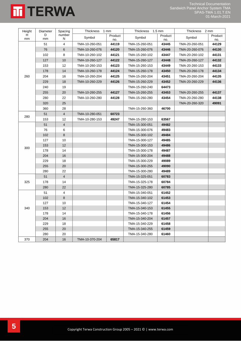
260
51 4 TMA-10-260-051 44119 TMA-15-260-051 43445 TMA-20-260-051 44129
76 6 TMA-10-260-076 44120 TMA-15-260-076 43446 TMA-20-260-076 44130
102 8 TMA-10-260-102 44121 TMA-15-260-102 43447 TMA-20-260-102 44131
127 10 TMA-10-260-127 44122 TMA-15-260-127 43448 TMA-20-260-127 44132
153 12 TMA-10-260-153 44123 TMA-15-260-153 43449 TMA-20-260-153 44133
178 14 TMA-10-260-178 44124 TMA-15-260-178 43450 TMA-20-260-178 44134
204 16 TMA-10-260-204 44125 TMA-15-260-204 43451 TMA-20-260-204 44135
229 18 TMA-10-260-229 44126 TMA-15-260-229 43452 TMA-20-260-229 44136
240 19 TMA-15-260-240 64473
255 20 TMA-10-260-255 44127 TMA-15-260-255 43453 TMA-20-260-255 44137
280 22 TMA-10-260-280 44128 TMA-15-260-280 43454 TMA-20-260-280 44138
320 25 TMA-20-260-320 49091
360 28 TMA-15-260-360 46700
280 51 4 TMA-10-280-051 60723
153 12 TMA-10-280-153 49247 TMA-15-280-153 63567
300
51 4 TMA-15-300-051 49482
76 6 TMA-15-300-076 49483
102 8 TMA-15-300-102 49484
127 10 TMA-15-300-127 49485
153 12 TMA-15-300-153 49486
178 14 TMA-15-300-178 49487
204 16 TMA-15-300-204 49488
229 18 TMA-15-300-229 49089
255 20 TMA-15-300-255 49090
280 22 TMA-15-300-280 49489
325
51 4 TMA-15-325-051 60783
178 14 TMA-15-325-178 60784
280 22 TMA-15-325-280 60785
51 4 TMA-15-340-051 61452
102 8 TMA-15-340-102 61453
127 10 TMA-15-340-127 61454
340 153 12 TMA-15-340-153 61455
178 14 TMA-15-340-178 61456
204 16 TMA-15-340-204 61457
229 18 TMA-15-340-229 61458
255 20 TMA-15-340-255 61459
280 20 TMA-15-340-280 61460
370 204 16 TMA-10-370-204 65817
Technical Documentation Sandwich Panel Anchor System TMA
SPAS-TMA 1.01.T.EN 01-March-2021
6 Copyright Terwa Construction Group 2005 – 2021 © | www.terwa.com
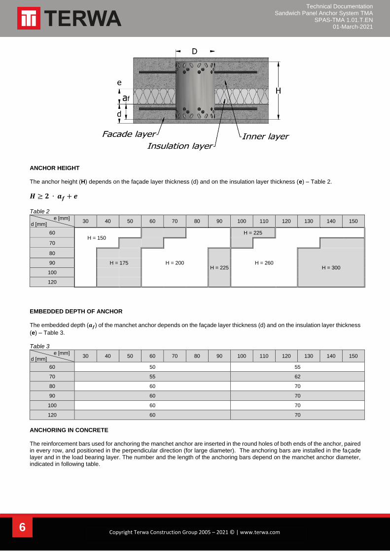
ANCHOR HEIGHT The anchor height (H) depends on the façade layer thickness (d) and on the insulation layer thickness (e) – Table 2.
𝑯 ≥ 𝟐 ∙ 𝒂𝒇 + 𝒆
Table 2
e [mm] d [mm]
30 40 50 60 70 80 90 100 110 120 130 140 150
60 H = 150
H = 225
70
80
H = 225
H = 300 90 H = 175 H = 200 H = 260
100
120
EMBEDDED DEPTH OF ANCHOR
The embedded depth (𝒂𝒇) of the manchet anchor depends on the façade layer thickness (d) and on the insulation layer thickness
(e) – Table 3. Table 3
e [mm] d [mm]
30 40 50 60 70 80 90 100 110 120 130 140 150
60 50 55
70 55 62
80 60 70
90 60 70
100 60 70
120 60 70
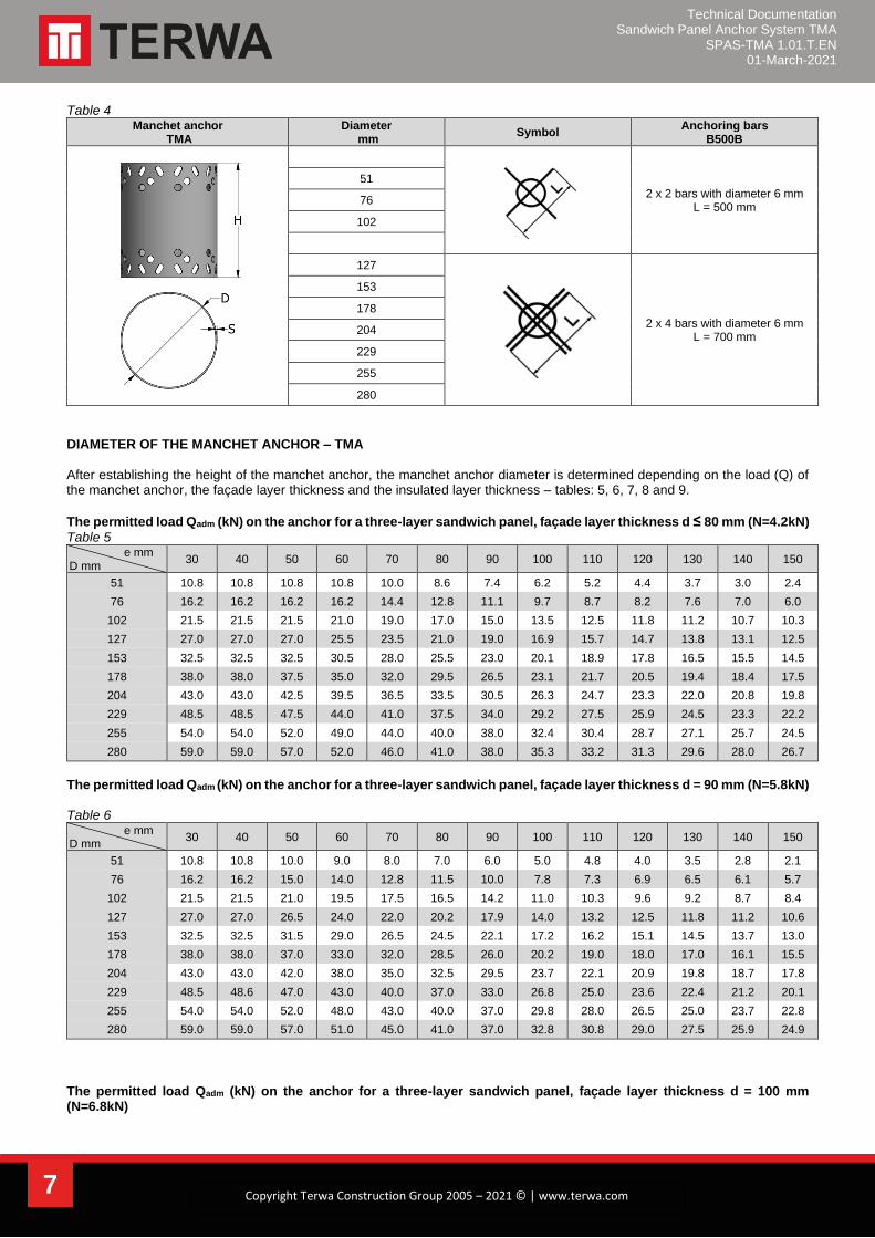
ANCHORING IN CONCRETE The reinforcement bars used for anchoring the manchet anchor are inserted in the round holes of both ends of the anchor, paired in every row, and positioned in the perpendicular direction (for large diameter). The anchoring bars are installed in the façade layer and in the load bearing layer. The number and the length of the anchoring bars depend on the manchet anchor diameter, indicated in following table.
Technical Documentation Sandwich Panel Anchor System TMA
SPAS-TMA 1.01.T.EN 01-March-2021
7 Copyright Terwa Construction Group 2005 – 2021 © | www.terwa.com
Table 4 Manchet anchor
TMA Diameter
mm Symbol
Anchoring bars B500B
2 x 2 bars with diameter 6 mm L = 500 mm
51
76
102
127
2 x 4 bars with diameter 6 mm L = 700 mm
153
178
204
229
255
280
DIAMETER OF THE MANCHET ANCHOR – TMA After establishing the height of the manchet anchor, the manchet anchor diameter is determined depending on the load (Q) of the manchet anchor, the façade layer thickness and the insulated layer thickness – tables: 5, 6, 7, 8 and 9.
The permitted load Qadm (kN) on the anchor for a three-layer sandwich panel, façade layer thickness d ≤ 80 mm (N=4.2kN)
Table 5 e mm
D mm 30 40 50 60 70 80 90 100 110 120 130 140 150
51 10.8 10.8 10.8 10.8 10.0 8.6 7.4 6.2 5.2 4.4 3.7 3.0 2.4
76 16.2 16.2 16.2 16.2 14.4 12.8 11.1 9.7 8.7 8.2 7.6 7.0 6.0
102 21.5 21.5 21.5 21.0 19.0 17.0 15.0 13.5 12.5 11.8 11.2 10.7 10.3
127 27.0 27.0 27.0 25.5 23.5 21.0 19.0 16.9 15.7 14.7 13.8 13.1 12.5
153 32.5 32.5 32.5 30.5 28.0 25.5 23.0 20.1 18.9 17.8 16.5 15.5 14.5
178 38.0 38.0 37.5 35.0 32.0 29.5 26.5 23.1 21.7 20.5 19.4 18.4 17.5
204 43.0 43.0 42.5 39.5 36.5 33.5 30.5 26.3 24.7 23.3 22.0 20.8 19.8
229 48.5 48.5 47.5 44.0 41.0 37.5 34.0 29.2 27.5 25.9 24.5 23.3 22.2
255 54.0 54.0 52.0 49.0 44.0 40.0 38.0 32.4 30.4 28.7 27.1 25.7 24.5
280 59.0 59.0 57.0 52.0 46.0 41.0 38.0 35.3 33.2 31.3 29.6 28.0 26.7
The permitted load Qadm (kN) on the anchor for a three-layer sandwich panel, façade layer thickness d = 90 mm (N=5.8kN) Table 6
e mm D mm
30 40 50 60 70 80 90 100 110 120 130 140 150
51 10.8 10.8 10.0 9.0 8.0 7.0 6.0 5.0 4.8 4.0 3.5 2.8 2.1
76 16.2 16.2 15.0 14.0 12.8 11.5 10.0 7.8 7.3 6.9 6.5 6.1 5.7
102 21.5 21.5 21.0 19.5 17.5 16.5 14.2 11.0 10.3 9.6 9.2 8.7 8.4
127 27.0 27.0 26.5 24.0 22.0 20.2 17.9 14.0 13.2 12.5 11.8 11.2 10.6
153 32.5 32.5 31.5 29.0 26.5 24.5 22.1 17.2 16.2 15.1 14.5 13.7 13.0
178 38.0 38.0 37.0 33.0 32.0 28.5 26.0 20.2 19.0 18.0 17.0 16.1 15.5
204 43.0 43.0 42.0 38.0 35.0 32.5 29.5 23.7 22.1 20.9 19.8 18.7 17.8
229 48.5 48.6 47.0 43.0 40.0 37.0 33.0 26.8 25.0 23.6 22.4 21.2 20.1
255 54.0 54.0 52.0 48.0 43.0 40.0 37.0 29.8 28.0 26.5 25.0 23.7 22.8
280 59.0 59.0 57.0 51.0 45.0 41.0 37.0 32.8 30.8 29.0 27.5 25.9 24.9
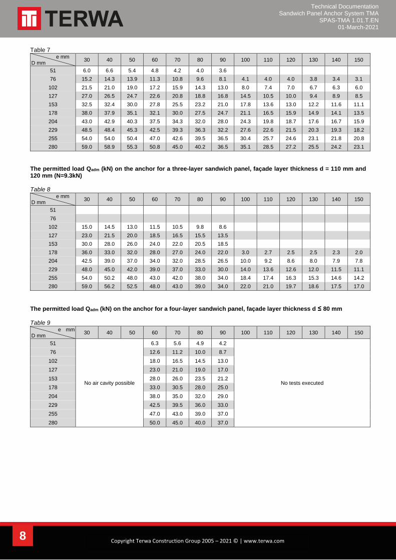
The permitted load Qadm (kN) on the anchor for a three-layer sandwich panel, façade layer thickness d = 100 mm (N=6.8kN)
Technical Documentation Sandwich Panel Anchor System TMA
SPAS-TMA 1.01.T.EN 01-March-2021
8 Copyright Terwa Construction Group 2005 – 2021 © | www.terwa.com
Table 7 e mm
D mm 30 40 50 60 70 80 90 100 110 120 130 140 150
51 6.0 6.6 5.4 4.8 4.2 4.0 3.6
76 15.2 14.3 13.9 11.3 10.8 9.6 8.1 4.1 4.0 4.0 3.8 3.4 3.1
102 21.5 21.0 19.0 17.2 15.9 14.3 13.0 8.0 7.4 7.0 6.7 6.3 6.0
127 27.0 26.5 24.7 22.6 20.8 18.8 16.8 14.5 10.5 10.0 9.4 8.9 8.5
153 32.5 32.4 30.0 27.8 25.5 23.2 21.0 17.8 13.6 13.0 12.2 11.6 11.1
178 38.0 37.9 35.1 32.1 30.0 27.5 24.7 21.1 16.5 15.9 14.9 14.1 13.5
204 43.0 42.9 40.3 37.5 34.3 32.0 28.0 24.3 19.8 18.7 17.6 16.7 15.9
229 48.5 48.4 45.3 42.5 39.3 36.3 32.2 27.6 22.6 21.5 20.3 19.3 18.2
255 54.0 54.0 50.4 47.0 42.6 39.5 36.5 30.4 25.7 24.6 23.1 21.8 20.8
280 59.0 58.9 55.3 50.8 45.0 40.2 36.5 35.1 28.5 27.2 25.5 24.2 23.1
The permitted load Qadm (kN) on the anchor for a three-layer sandwich panel, façade layer thickness d = 110 mm and 120 mm (N=9.3kN) Table 8
e mm D mm
30 40 50 60 70 80 90 100 110 120 130 140 150
51
76
102 15.0 14.5 13.0 11.5 10.5 9.8 8.6
127 23.0 21.5 20.0 18.5 16.5 15.5 13.5
153 30.0 28.0 26.0 24.0 22.0 20.5 18.5
178 36.0 33.0 32.0 28.0 27.0 24.0 22.0 3.0 2.7 2.5 2.5 2.3 2.0
204 42.5 39.0 37.0 34.0 32.0 28.5 26.5 10.0 9.2 8.6 8.0 7.9 7.8
229 48.0 45.0 42.0 39.0 37.0 33.0 30.0 14.0 13.6 12.6 12.0 11.5 11.1
255 54.0 50.2 48.0 43.0 42.0 38.0 34.0 18.4 17.4 16.3 15.3 14.6 14.2
280 59.0 56.2 52.5 48.0 43.0 39.0 34.0 22.0 21.0 19.7 18.6 17.5 17.0
The permitted load Qadm (kN) on the anchor for a four-layer sandwich panel, façade layer thickness d ≤ 80 mm
Table 9 e mm D mm
30 40 50 60 70 80 90 100 110 120 130 140 150
51
No air cavity possible
6.3 5.6 4.9 4.2
No tests executed
76 12.6 11.2 10.0 8.7
102 18.0 16.5 14.5 13.0
127 23.0 21.0 19.0 17.0
153 28.0 26.0 23.5 21.2
178 33.0 30.5 28.0 25.0
204 38.0 35.0 32.0 29.0
229 42.5 39.5 36.0 33.0
255 47.0 43.0 39.0 37.0
280 50.0 45.0 40.0 37.0
Technical Documentation Sandwich Panel Anchor System TMA
SPAS-TMA 1.01.T.EN 01-March-2021
9 Copyright Terwa Construction Group 2005 – 2021 © | www.terwa.com
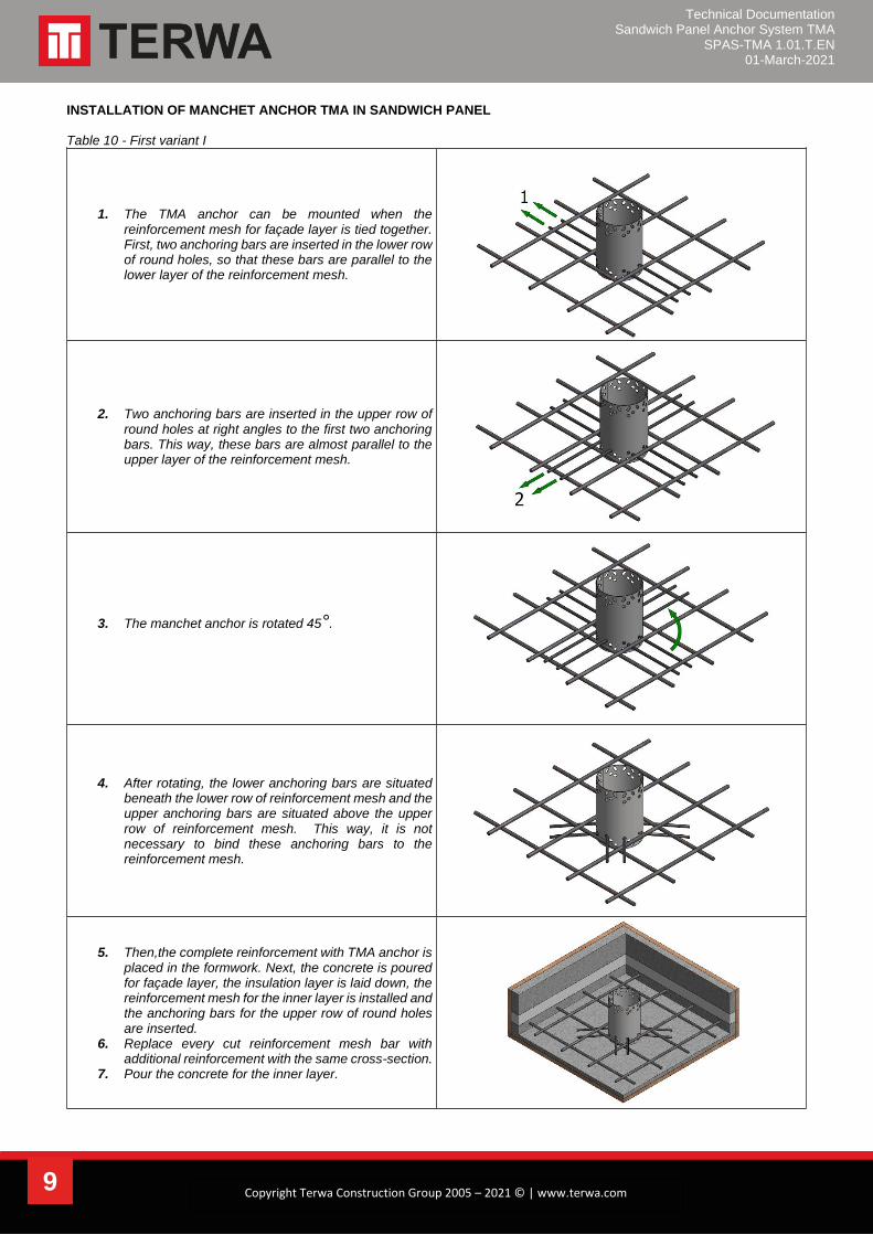
INSTALLATION OF MANCHET ANCHOR TMA IN SANDWICH PANEL Table 10 - First variant I
1. The TMA anchor can be mounted when the reinforcement mesh for façade layer is tied together. First, two anchoring bars are inserted in the lower row of round holes, so that these bars are parallel to the lower layer of the reinforcement mesh.
2. Two anchoring bars are inserted in the upper row of round holes at right angles to the first two anchoring bars. This way, these bars are almost parallel to the upper layer of the reinforcement mesh.
3. The manchet anchor is rotated 45°.
4. After rotating, the lower anchoring bars are situated beneath the lower row of reinforcement mesh and the upper anchoring bars are situated above the upper row of reinforcement mesh. This way, it is not necessary to bind these anchoring bars to the reinforcement mesh.
5. Then,the complete reinforcement with TMA anchor is placed in the formwork. Next, the concrete is poured for façade layer, the insulation layer is laid down, the reinforcement mesh for the inner layer is installed and the anchoring bars for the upper row of round holes are inserted.
6. Replace every cut reinforcement mesh bar with additional reinforcement with the same cross-section.
7. Pour the concrete for the inner layer.
Technical Documentation Sandwich Panel Anchor System TMA
SPAS-TMA 1.01.T.EN 01-March-2021
10 Copyright Terwa Construction Group 2005 – 2021 © | www.terwa.com
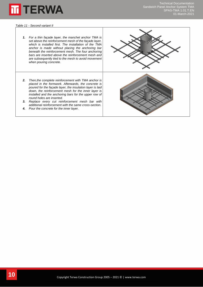
Table 11 - Second variant II
1. For a thin façade layer, the manchet anchor TMA is set above the reinforcement mesh of the façade layer, which is installed first. The installation of the TMA anchor is made without placing the anchoring bar beneath the reinforcement mesh. The four anchoring bars are inserted above the reinforcement mesh and are subsequently tied to the mesh to avoid movement when pouring concrete.
2. Then,the complete reinforcement with TMA anchor is placed in the formwork. Afterwards, the concrete is poured for the façade layer, the insulation layer is laid down, the reinforcement mesh for the inner layer is installed and the anchoring bars for the upper row of round holes are inserted.
3. Replace every cut reinforcement mesh bar with additional reinforcement with the same cross-section.
4. Pour the concrete for the inner layer.
Technical Documentation Sandwich Panel Anchor System TMA
SPAS-TMA 1.01.T.EN 01-March-2021
11 Copyright Terwa Construction Group 2005 – 2021 © | www.terwa.com
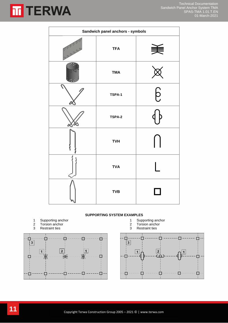
Sandwich panel anchors - symbols
TFA
TMA
TSPA-1
TSPA-2
TVH
TVA
TVB
SUPPORTING SYSTEM EXAMPLES
1 Supporting anchor 2 Torsion anchor 3 Restraint ties
1 Supporting anchor 2 Torsion anchor 3 Restraint ties

Technical Documentation Sandwich Panel Anchor System TMA
SPAS-TMA 1.01.T.EN 01-March-2021
12 Copyright Terwa Construction Group 2005 – 2021 © | www.terwa.com
GENERAL INFORMATION Sandwich panels are primarily big, multilayer façade elements made of reinforced concrete. They consist of a façade layer which is made from aesthetic concrete or structural concrete, an insulation layer, and an inner load-bearing layer (panel consisting of three layers). To avoid problems caused by condensation, a ventilated cavity may be applied between the insulation layer and the façade layer (panel consisting of four layers). The façade layer is connected to the load-bearing layer by sandwich panel anchors. The sandwich panel anchors are a combination of supporting anchors, torsion anchors and panel ties. These anchors have to be dimensioned taking the following factors into account:
• Weight of the façade layer.
• Insulation thickness and width of the ventilated cavity
• Adhesion forces to formwork.
• Wind pressure and suction.
• Eccentricities, especially for asymmetrical elements.
• Temperature influences on the façade layer.
• Temperature difference between inner and façade layer.
• Transportation and mounting of the sandwich panel.
• Dilation and shrinkage forces.
ANCHORING SYSTEM
• LOAD BEARING ANCHORS These anchors have to be dimensioned to the base of the individual weight of the façade layer. Eccentric loads, as well as horizontal loads from wind and warping, etc. should also be considered. Supporting anchors have to be placed in such a way that only one anchoring point (fulcrum) is available per façade layer. If only one supporting anchor is used for the load transfer, a torsion anchor is also required.
• TORSION/HORIZONTAL ANCHORS
Torsion anchors stop the façade layer from twisting around the load-bearing layer. The type of torsion anchor has to be dimensioned taking into account an unintentional eccentricity of the installation of the supporting anchor (the supporting anchor is not placed in the centroidal axis). This eccentricity is supposed to be 5% of the overall length of the sandwich panel, with a minimum value of 100 mm. Installing a torsion anchor is not necessary when at least 2 supporting anchors are used to sustain the façade layer. In this case, the load distribution principle is a beam at 2 support points. The façade layer is additionally connected to the load-bearing layer using retaining anchors.
• PANEL TIES Retaining anchors bear the normal forces from wind, adhesion to formwork and deformation, etc.
Quality Terwa continuously controls the anchor production process in terms of strength, dimensional and material quality, and performs all of the required inspections to ensure a system with superior quality. All of the products are tracked from material acquisition to the final, ready to use product.
Marking and traceability All anchors have all necessary data for traceability.
Technical Documentation Sandwich Panel Anchor System TMA
SPAS-TMA 1.01.T.EN 01-March-2021
13 Copyright Terwa Construction Group 2005 – 2021 © | www.terwa.com
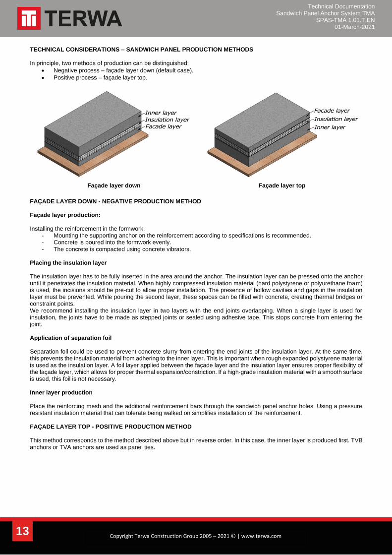
TECHNICAL CONSIDERATIONS – SANDWICH PANEL PRODUCTION METHODS In principle, two methods of production can be distinguished:
• Negative process – façade layer down (default case).
• Positive process – façade layer top.
Façade layer down Façade layer top
FAÇADE LAYER DOWN - NEGATIVE PRODUCTION METHOD Façade layer production: Installing the reinforcement in the formwork.
- Mounting the supporting anchor on the reinforcement according to specifications is recommended. - Concrete is poured into the formwork evenly. - The concrete is compacted using concrete vibrators.
Placing the insulation layer The insulation layer has to be fully inserted in the area around the anchor. The insulation layer can be pressed onto the anchor until it penetrates the insulation material. When highly compressed insulation material (hard polystyrene or polyurethane foam) is used, the incisions should be pre-cut to allow proper installation. The presence of hollow cavities and gaps in the insulation layer must be prevented. While pouring the second layer, these spaces can be filled with concrete, creating thermal bridges or constraint points. We recommend installing the insulation layer in two layers with the end joints overlapping. When a single layer is used for insulation, the joints have to be made as stepped joints or sealed using adhesive tape. This stops concrete from entering the joint. Application of separation foil Separation foil could be used to prevent concrete slurry from entering the end joints of the insulation layer. At the same time, this prevents the insulation material from adhering to the inner layer. This is important when rough expanded polystyrene material is used as the insulation layer. A foil layer applied between the façade layer and the insulation layer ensures proper flexibility of the façade layer, which allows for proper thermal expansion/constriction. If a high-grade insulation material with a smooth surface is used, this foil is not necessary. Inner layer production Place the reinforcing mesh and the additional reinforcement bars through the sandwich panel anchor holes. Using a pressure resistant insulation material that can tolerate being walked on simplifies installation of the reinforcement. FAÇADE LAYER TOP - POSITIVE PRODUCTION METHOD This method corresponds to the method described above but in reverse order. In this case, the inner layer is produced first. TVB anchors or TVA anchors are used as panel ties.
Technical Documentation Sandwich Panel Anchor System TMA
SPAS-TMA 1.01.T.EN 01-March-2021
14 Copyright Terwa Construction Group 2005 – 2021 © | www.terwa.com
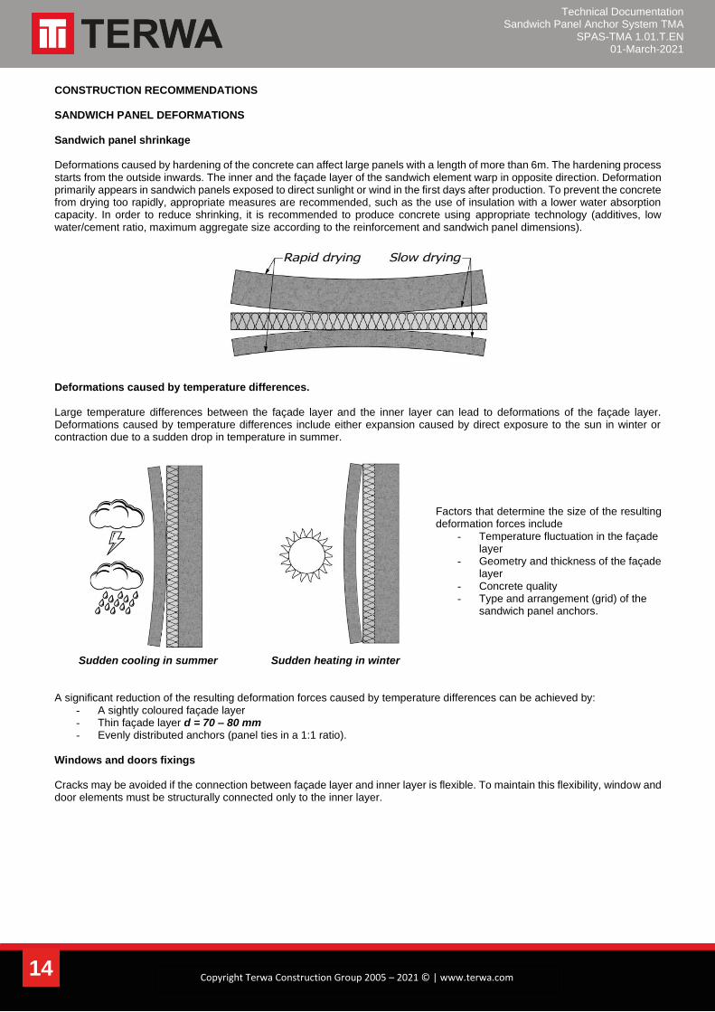
CONSTRUCTION RECOMMENDATIONS SANDWICH PANEL DEFORMATIONS Sandwich panel shrinkage Deformations caused by hardening of the concrete can affect large panels with a length of more than 6m. The hardening process starts from the outside inwards. The inner and the façade layer of the sandwich element warp in opposite direction. Deformation primarily appears in sandwich panels exposed to direct sunlight or wind in the first days after production. To prevent the concrete from drying too rapidly, appropriate measures are recommended, such as the use of insulation with a lower water absorption capacity. In order to reduce shrinking, it is recommended to produce concrete using appropriate technology (additives, low water/cement ratio, maximum aggregate size according to the reinforcement and sandwich panel dimensions).
Deformations caused by temperature differences. Large temperature differences between the façade layer and the inner layer can lead to deformations of the façade layer. Deformations caused by temperature differences include either expansion caused by direct exposure to the sun in winter or contraction due to a sudden drop in temperature in summer.
Factors that determine the size of the resulting deformation forces include
- Temperature fluctuation in the façade layer
- Geometry and thickness of the façade layer
- Concrete quality - Type and arrangement (grid) of the
sandwich panel anchors.
Sudden cooling in summer Sudden heating in winter A significant reduction of the resulting deformation forces caused by temperature differences can be achieved by:
- A sightly coloured façade layer - Thin façade layer d = 70 – 80 mm - Evenly distributed anchors (panel ties in a 1:1 ratio).
Windows and doors fixings Cracks may be avoided if the connection between façade layer and inner layer is flexible. To maintain this flexibility, window and door elements must be structurally connected only to the inner layer.
Technical Documentation Sandwich Panel Anchor System TMA
SPAS-TMA 1.01.T.EN 01-March-2021
15 Copyright Terwa Construction Group 2005 – 2021 © | www.terwa.com
SANDWICH PANEL DIMENSIONING
In principle, large sandwich panels of over 6 m must be avoided. For an element length of more than 6 metres, the risk of cracking increases, especially for thinner plates. In general, a maximum element length of a 7.5 m is recommended. If longer lengths are required for architectural or constructional reasons, splitting the façade layer with an expansion joint is recommended, while the inner layer is still produced in one piece.
THE ANCHORAGE CENTRE (FULCRUM)
The anchorage centre should be situated mostly in the geometric middle of the panel. The change of length ΔL due temperature influences increase with increasing distance from the anchorage centre (fulcrum). To maintain a minimum value for ΔL, the anchorage centre may be in the middle of the panel. The stiffness of the anchoring elements (supporting anchors, retaining anchors) prevents deformations of the sandwich panel. The resulting constraining forces which act against the panel can cause damage. These constraining forces can be reduced by using an insulation layer with a greater thickness, providing the connecting anchors with a greater range of mobility. The maximum permissible distances of the connecting anchors to the anchorage centre therefore depend on the thickness of the insulation layer.
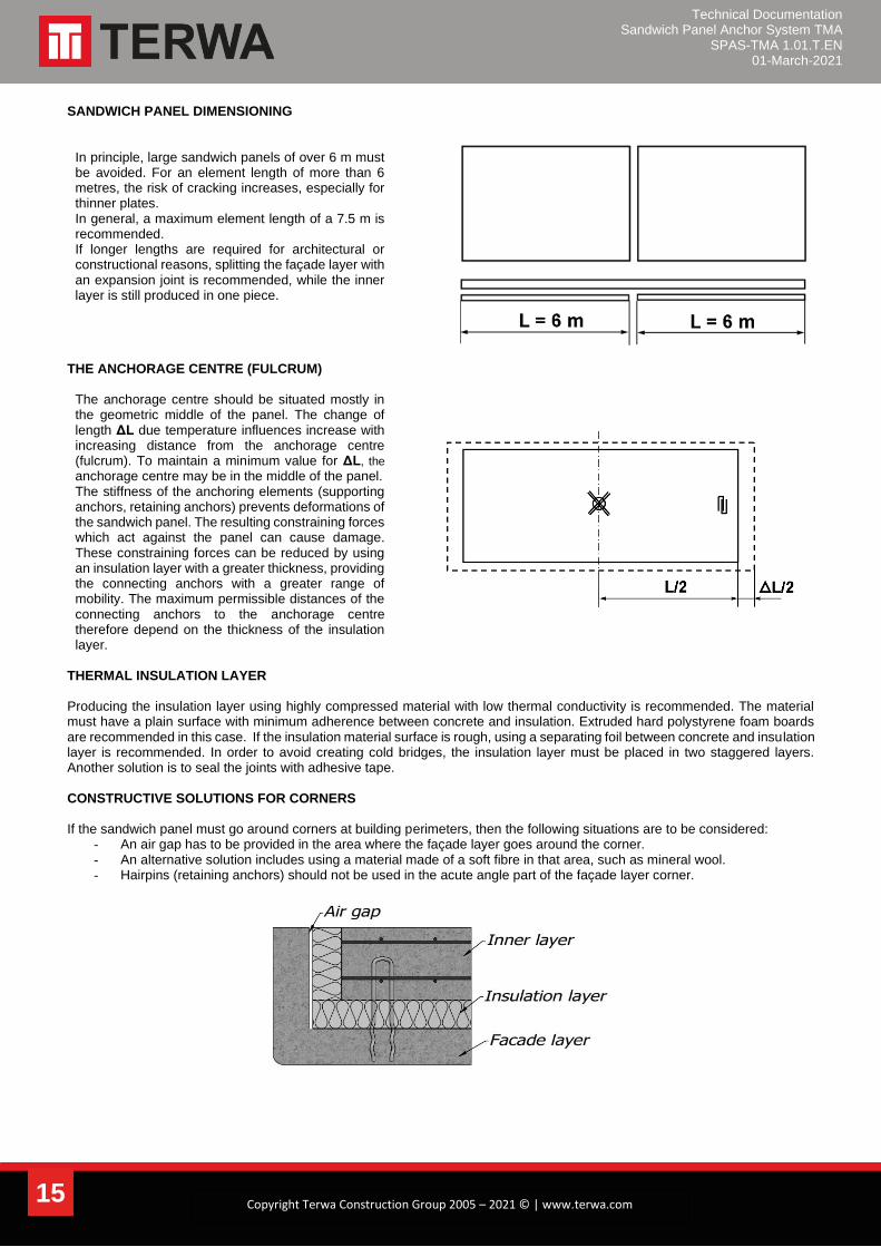
THERMAL INSULATION LAYER Producing the insulation layer using highly compressed material with low thermal conductivity is recommended. The material must have a plain surface with minimum adherence between concrete and insulation. Extruded hard polystyrene foam boards are recommended in this case. If the insulation material surface is rough, using a separating foil between concrete and insulation layer is recommended. In order to avoid creating cold bridges, the insulation layer must be placed in two staggered layers. Another solution is to seal the joints with adhesive tape. CONSTRUCTIVE SOLUTIONS FOR CORNERS If the sandwich panel must go around corners at building perimeters, then the following situations are to be considered:
- An air gap has to be provided in the area where the façade layer goes around the corner. - An alternative solution includes using a material made of a soft fibre in that area, such as mineral wool. - Hairpins (retaining anchors) should not be used in the acute angle part of the façade layer corner.

Technical Documentation Sandwich Panel Anchor System TMA
SPAS-TMA 1.01.T.EN 01-March-2021
16 Copyright Terwa Construction Group 2005 – 2021 © | www.terwa.com
INNER LAYER – LOAD-BEARING LAYER The inner layer is more rigid than the façade layer and for this reason, transfers its deformation onto the façade layer. To reduce these deformations to a minimum, the inner layer thickness must be at least 50% thicker than the façade layer. OUTER LAYER – FAÇADE LAYER The thickness of the façade layer must be a minimum of 70 mm according to EN 1992-1-1. Reinforcement mesh of 131 mm²/m must be used for SPA anchors and 188 mm²/m for TMA and TFA anchor. The additional reinforcements which are required in the sandwich anchors zone in the façade layer are indicated in the tables. CONCRETE QUALITY The permissible load capacities for sandwich panel anchors, which are indicated in the tables, are available for a minimum concrete quality of C30/37. SANDWICH PANEL WITH A SUPPLEMENTAL LAYER FOR VENTILATION For 4-layer sandwich panels, an extra air layer of 40mm is provided between the outer layer and the insulation layer to prevent condensation problems. A special cleated foil made of PVC can be used for this. It is laid on the outer concrete layer (with the cleats facing upwards) during the sandwich panel production process. The foil must have cut-outs by the bearing and torsion anchors. The insulation material is then applied and the inner layer can be poured. Important: for 4-layer panels, consider that the permissible load capacity of the manchet anchors is reduced. SANDWICH PANEL ANCHOR CALCULATION BASIC INFORMATION
The calculation values for the load capacities 𝑉𝑅𝑑, 𝑁𝑅𝑑, 𝑀𝑅𝑑 are resistance values taking the partial safety factor for the material into account. These resistance values 𝑉𝑅𝑑, 𝑁𝑅𝑑, and 𝑀𝑅𝑑 need to be compared with the partial safety coefficient increased action
𝑉𝐸𝑑 (vertical loads – dead load of the façade layer and any additional loads present), 𝑁𝐸𝑑 (horizontal loads – wind loads and
deformation) and 𝑀𝐸𝑑 (only for TFA anchors) as specified in the appropriate approval. The horizontal loads depend on the slab geometry, the grid spacing and the anchor positions. Design loads
• Vertical loads - Loads acting as vertical loads must be considered, such as the dead weight of the façade layer, plus any existing additional loads.
• Warp loads – multiple factors can affect the warping, such as anchor arrangement in a grid with a side-ratio of 0.75 ≤ 𝑙𝑥/𝑙𝑦 ≤ 1.33, façade layer thickness (70 – 120 mm), temperature stresses.
• Wind loads – according to EN 1991-1-4 and national annexes. A sandwich panel with an anchor grid of maximum 1.20m x 1.20m is assumed.
• Distance from anchor to the anchorage centre (fulcrum) – The admissible distances depend on the following factors: heat insulation thickness and temperature stress.
Technical Documentation Sandwich Panel Anchor System TMA
SPAS-TMA 1.01.T.EN 01-March-2021
17 Copyright Terwa Construction Group 2005 – 2021 © | www.terwa.com
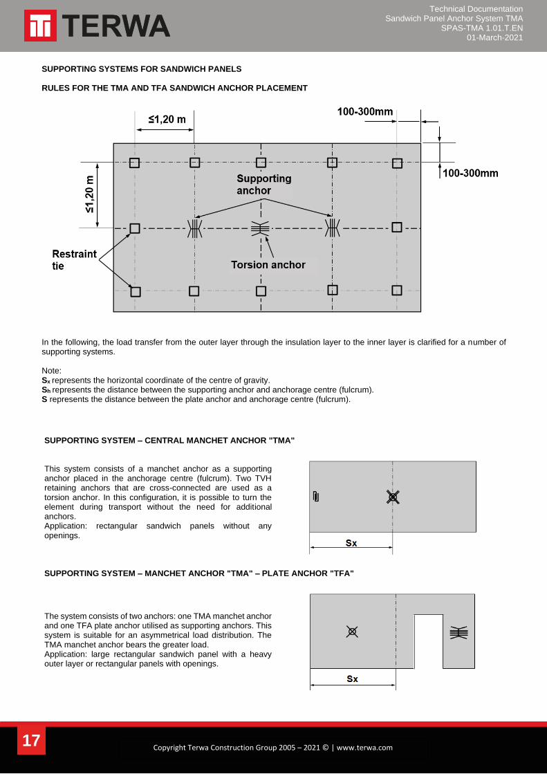
SUPPORTING SYSTEMS FOR SANDWICH PANELS RULES FOR THE TMA AND TFA SANDWICH ANCHOR PLACEMENT
In the following, the load transfer from the outer layer through the insulation layer to the inner layer is clarified for a number of supporting systems. Note: Sx represents the horizontal coordinate of the centre of gravity. Sh represents the distance between the supporting anchor and anchorage centre (fulcrum). S represents the distance between the plate anchor and anchorage centre (fulcrum).
SUPPORTING SYSTEM – CENTRAL MANCHET ANCHOR "TMA"
This system consists of a manchet anchor as a supporting anchor placed in the anchorage centre (fulcrum). Two TVH retaining anchors that are cross-connected are used as a torsion anchor. In this configuration, it is possible to turn the element during transport without the need for additional anchors. Application: rectangular sandwich panels without any openings.
SUPPORTING SYSTEM – MANCHET ANCHOR "TMA" – PLATE ANCHOR "TFA"
The system consists of two anchors: one TMA manchet anchor and one TFA plate anchor utilised as supporting anchors. This system is suitable for an asymmetrical load distribution. The TMA manchet anchor bears the greater load. Application: large rectangular sandwich panel with a heavy outer layer or rectangular panels with openings.

Technical Documentation Sandwich Panel Anchor System TMA
SPAS-TMA 1.01.T.EN 01-March-2021
18 Copyright Terwa Construction Group 2005 – 2021 © | www.terwa.com
SUPPORTING SYSTEM – PLATE ANCHOR "TFA" IN PANELS WITHOUT OPENINGS
Two TFA plate anchors as supporting anchors (to avoid confusion, plate anchors from the same load range must be used for an asymmetrical load distribution). Use one plate anchor placed horizontally for stiffening. Application: long, slender, rectangular sandwich panel.
Sandwich panels with TFA anchors arranged at 90˚ to one another.
SUPPORTING SYSTEM – PLATE ANCHOR "TFA" IN PANELS WITH OPENINGS
Two TFA plate anchors as supporting anchors. The anchorage centre is at the panel’s centre of gravity. Please note for thin insulation layers (the distance "S" between the plate anchor and anchorage centre must be verified. Application: sandwich panels with large openings in the centre.
Window or door openings can prevent placement of the anchorage centre in the middle of the sandwich panel. The maximum possible distance between anchors and the anchorage centre is determined by the potential deformation of the anchors. For determining which supporting system and anchoring parts must be used, the maximum distances to the anchorage centre
indicated for the retaining anchors (Sh) and plate anchors (S) must not be exceeded.
The values for "Sh" and "S" can be increased by adding an extra strip of insulation material in the retaining anchor or plate
anchor zone.
Technical Documentation Sandwich Panel Anchor System TMA
SPAS-TMA 1.01.T.EN 01-March-2021
19 Copyright Terwa Construction Group 2005 – 2021 © | www.terwa.com
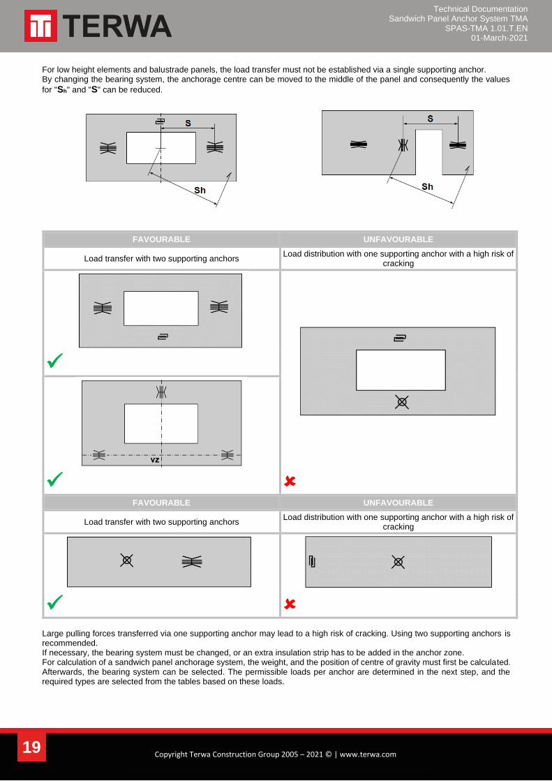
For low height elements and balustrade panels, the load transfer must not be established via a single supporting anchor. By changing the bearing system, the anchorage centre can be moved to the middle of the panel and consequently the values
for "Sh" and "S" can be reduced.
FAVOURABLE UNFAVOURABLE
Load transfer with two supporting anchors Load distribution with one supporting anchor with a high risk of
cracking
✓
✓
FAVOURABLE UNFAVOURABLE
Load transfer with two supporting anchors Load distribution with one supporting anchor with a high risk of
cracking
✓
Large pulling forces transferred via one supporting anchor may lead to a high risk of cracking. Using two supporting anchors is recommended. If necessary, the bearing system must be changed, or an extra insulation strip has to be added in the anchor zone. For calculation of a sandwich panel anchorage system, the weight, and the position of centre of gravity must first be calculated. Afterwards, the bearing system can be selected. The permissible loads per anchor are determined in the next step, and the required types are selected from the tables based on these loads.
Technical Documentation Sandwich Panel Anchor System TMA
SPAS-TMA 1.01.T.EN 01-March-2021
20 Copyright Terwa Construction Group 2005 – 2021 © | www.terwa.com
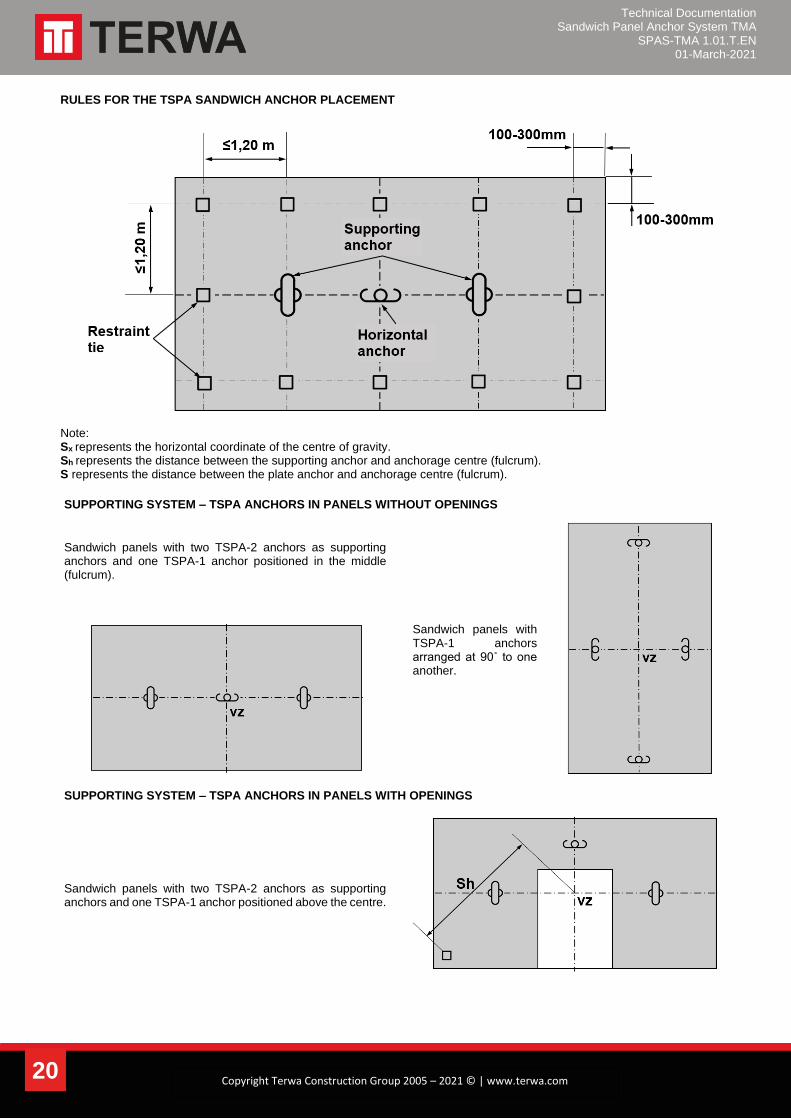
RULES FOR THE TSPA SANDWICH ANCHOR PLACEMENT
Note: Sx represents the horizontal coordinate of the centre of gravity. Sh represents the distance between the supporting anchor and anchorage centre (fulcrum). S represents the distance between the plate anchor and anchorage centre (fulcrum).
SUPPORTING SYSTEM – TSPA ANCHORS IN PANELS WITHOUT OPENINGS
Sandwich panels with two TSPA-2 anchors as supporting anchors and one TSPA-1 anchor positioned in the middle (fulcrum).
Sandwich panels with TSPA-1 anchors arranged at 90˚ to one another.
SUPPORTING SYSTEM – TSPA ANCHORS IN PANELS WITH OPENINGS
Sandwich panels with two TSPA-2 anchors as supporting anchors and one TSPA-1 anchor positioned above the centre.

Technical Documentation Sandwich Panel Anchor System TMA
SPAS-TMA 1.01.T.EN 01-March-2021
21 Copyright Terwa Construction Group 2005 – 2021 © | www.terwa.com
MIXED SYSTEM - TSPA AND PLATE ANCHOR "TFA" IN PANELS WITH A SMALL WIDTH
Due to the height of the anchors and the direction of the reinforcement, in sandwich panels with minimal width, it is recommended to install TSPA as horizontal anchors and two TFA as a supporting anchor.
FAVOURABLE UNFAVOURABLE
MIXED SYSTEM - TSPA AND PLATE ANCHOR "TFA" IN PANELS WITH A SMALL LINTEL
Due to the height of the anchors and the direction of the reinforcement, in sandwich panels with minimal lintel, it is recommended to install TSPA as horizontal anchors and two TFA as a supporting anchor.
In sandwich panels with posts next to openings with a small lintel, it is recommended to use a TSPA-1 anchor and a supporting anchor dimensioned for column load.
SUPPORTING SYSTEM – TSPA, TFA AND PANEL TIES INSTALLED IN SPECIAL PANELS
In sandwich panels with small widths, the restraint ties should be arranged in pairs or staggered. This must be done even if the minimum axis or edge distance is not according to the indicated dimensions.
For a small width adjacent to door openings, it is also recommended to used restraint ties installed in pairs.
Technical Documentation Sandwich Panel Anchor System TMA
SPAS-TMA 1.01.T.EN 01-March-2021
22 Copyright Terwa Construction Group 2005 – 2021 © | www.terwa.com
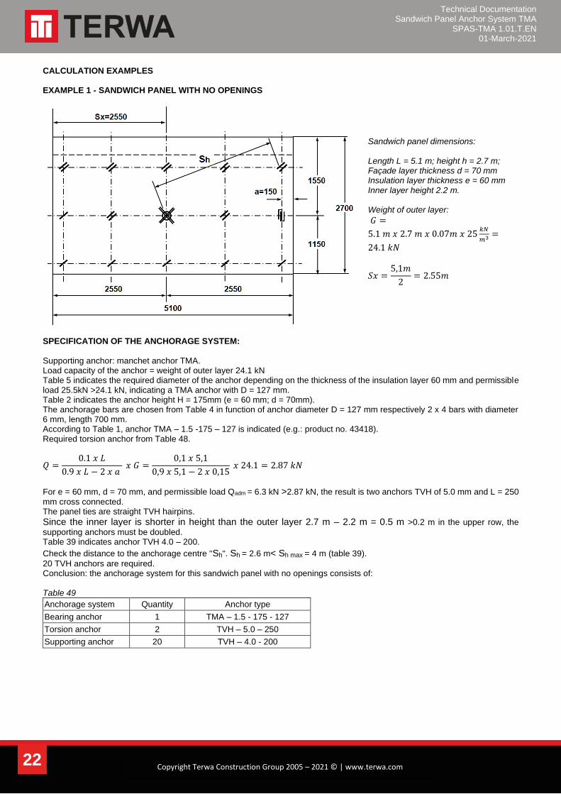
CALCULATION EXAMPLES EXAMPLE 1 - SANDWICH PANEL WITH NO OPENINGS
Sandwich panel dimensions: Length L = 5.1 m; height h = 2.7 m; Façade layer thickness d = 70 mm Insulation layer thickness e = 60 mm Inner layer height 2.2 m. Weight of outer layer:
𝐺 =
5.1 𝑚 𝑥 2.7 𝑚 𝑥 0.07𝑚 𝑥 25𝑘𝑁
𝑚3 =
24.1 𝑘𝑁
𝑆𝑥 =5,1𝑚
2= 2.55𝑚
SPECIFICATION OF THE ANCHORAGE SYSTEM: Supporting anchor: manchet anchor TMA. Load capacity of the anchor = weight of outer layer 24.1 kN Table 5 indicates the required diameter of the anchor depending on the thickness of the insulation layer 60 mm and permissible load 25.5kN >24.1 kN, indicating a TMA anchor with D = 127 mm. Table 2 indicates the anchor height H = 175mm (e = 60 mm; d = 70mm). The anchorage bars are chosen from Table 4 in function of anchor diameter D = 127 mm respectively 2 x 4 bars with diameter 6 mm, length 700 mm. According to Table 1, anchor TMA – 1.5 -175 – 127 is indicated (e.g.: product no. 43418). Required torsion anchor from Table 48.
𝑄 =0.1 𝑥 𝐿
0.9 𝑥 𝐿 − 2 𝑥 𝑎 𝑥 𝐺 =
0,1 𝑥 5,1
0,9 𝑥 5,1 − 2 𝑥 0,15 𝑥 24.1 = 2.87 𝑘𝑁
For e = 60 mm, d = 70 mm, and permissible load Qadm = 6.3 kN >2.87 kN, the result is two anchors TVH of 5.0 mm and L = 250
mm cross connected. The panel ties are straight TVH hairpins.
Since the inner layer is shorter in height than the outer layer 2.7 m – 2.2 m = 0.5 m >0.2 m in the upper row, the
supporting anchors must be doubled. Table 39 indicates anchor TVH 4.0 – 200.
Check the distance to the anchorage centre "Sh". Sh = 2.6 m< Sh max = 4 m (table 39).
20 TVH anchors are required. Conclusion: the anchorage system for this sandwich panel with no openings consists of: Table 49
Anchorage system Quantity Anchor type
Bearing anchor 1 TMA – 1.5 - 175 - 127
Torsion anchor 2 TVH – 5.0 – 250
Supporting anchor 20 TVH – 4.0 - 200
Technical Documentation Sandwich Panel Anchor System TMA
SPAS-TMA 1.01.T.EN 01-March-2021
23 Copyright Terwa Construction Group 2005 – 2021 © | www.terwa.com
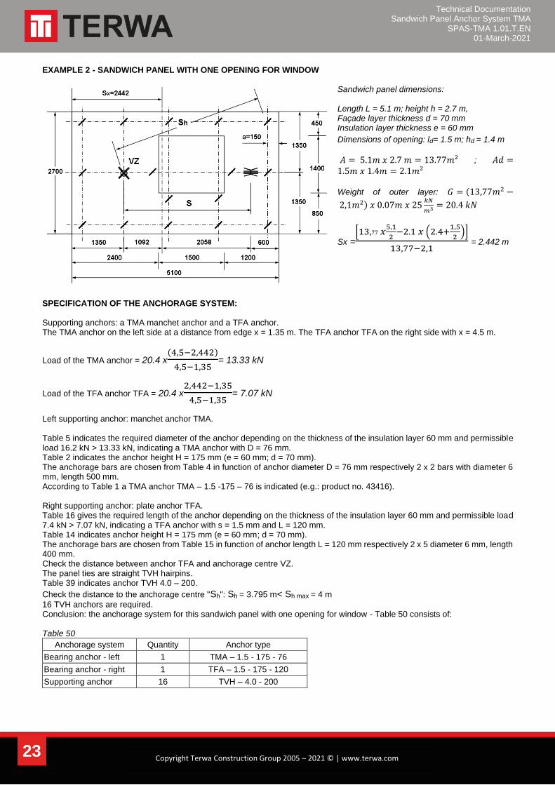
EXAMPLE 2 - SANDWICH PANEL WITH ONE OPENING FOR WINDOW
Sandwich panel dimensions: Length L = 5.1 m; height h = 2.7 m, Façade layer thickness d = 70 mm Insulation layer thickness e = 60 mm
Dimensions of opening: ld= 1.5 m; hd = 1.4 m
𝐴 = 5.1𝑚 𝑥 2.7 𝑚 = 13.77𝑚² ; 𝐴𝑑 =1.5𝑚 𝑥 1.4𝑚 = 2.1𝑚²
Weight of outer layer: 𝐺 = (13,77𝑚2 −
2,1𝑚2) 𝑥 0.07𝑚 𝑥 25𝑘𝑁
𝑚3 = 20.4 𝑘𝑁
Sx =[13,77 𝑥
5,1
2−2.1 𝑥 (2.4+
1,5
2)]
13,77−2,1 = 2.442 m
SPECIFICATION OF THE ANCHORAGE SYSTEM: Supporting anchors: a TMA manchet anchor and a TFA anchor. The TMA anchor on the left side at a distance from edge x = 1.35 m. The TFA anchor TFA on the right side with x = 4.5 m.
Load of the TMA anchor = 20.4 x(4,5−2,442)
4,5−1,35= 13.33 kN
Load of the TFA anchor TFA = 20.4 x2,442−1,35
4,5−1,35= 7.07 kN
Left supporting anchor: manchet anchor TMA. Table 5 indicates the required diameter of the anchor depending on the thickness of the insulation layer 60 mm and permissible load 16.2 kN > 13.33 kN, indicating a TMA anchor with D = 76 mm. Table 2 indicates the anchor height H = 175 mm (e = 60 mm; d = 70 mm). The anchorage bars are chosen from Table 4 in function of anchor diameter D = 76 mm respectively 2 x 2 bars with diameter 6 mm, length 500 mm. According to Table 1 a TMA anchor TMA – 1.5 -175 – 76 is indicated (e.g.: product no. 43416). Right supporting anchor: plate anchor TFA. Table 16 gives the required length of the anchor depending on the thickness of the insulation layer 60 mm and permissible load 7.4 kN > 7.07 kN, indicating a TFA anchor with s = 1.5 mm and L = 120 mm. Table 14 indicates anchor height H = 175 mm (e = 60 mm; d = 70 mm). The anchorage bars are chosen from Table 15 in function of anchor length L = 120 mm respectively 2 x 5 diameter 6 mm, length 400 mm. Check the distance between anchor TFA and anchorage centre VZ. The panel ties are straight TVH hairpins. Table 39 indicates anchor TVH 4.0 – 200.
Check the distance to the anchorage centre "Sh": Sh = 3.795 m< Sh max = 4 m
16 TVH anchors are required. Conclusion: the anchorage system for this sandwich panel with one opening for window - Table 50 consists of: Table 50
Anchorage system Quantity Anchor type
Bearing anchor - left 1 TMA – 1.5 - 175 - 76
Bearing anchor - right 1 TFA – 1.5 - 175 - 120
Supporting anchor 16 TVH – 4.0 - 200
Technical Documentation Sandwich Panel Anchor System TMA
SPAS-TMA 1.01.T.EN 01-March-2021
24 Copyright Terwa Construction Group 2005 – 2021 © | www.terwa.com
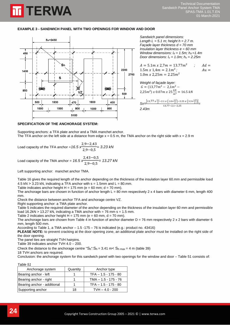
EXAMPLE 3 - SANDWICH PANEL WITH TWO OPENINGS FOR WINDOW AND DOOR
Sandwich panel dimensions: Length L = 5.1 m; height h = 2.7 m. Façade layer thickness d = 70 mm Insulation layer thickness e = 60 mm Window dimensions: ld = 1.5m; hd =1.4m Door dimensions: lu = 1.0m; hu = 2.25m
𝐴 = 5.1𝑚 𝑥 2,7𝑚 = 13.77𝑚² ; 𝐴𝑑 =1.5𝑚 𝑥 1,4𝑚 = 2.1𝑚² ; 𝐴𝑢 =1.0𝑚 𝑥 2,25𝑚 = 2.25𝑚²
Weight of façade layer:
𝐺 = (13,77𝑚2 − 2,1𝑚2 −
2,25𝑚²) 𝑥 0.07𝑚 𝑥 25𝑘𝑁
𝑚3 = 16.5 𝑘𝑁
Sx=[13,77 𝑥
5,1
2−2.1 𝑥 (1.0+
1,5
2)−2.25 𝑥 (3.3+
1,0
2)]
13,77−2,1−2,25=
2.43m
SPECIFICATION OF THE ANCHORAGE SYSTEM: Supporting anchors: a TFA plate anchor and a TMA manchet anchor. The TFA anchor on the left side at a distance from edge x = 0.5 m, the TMA anchor on the right side with x = 2.9 m
Load capacity of the TFA anchor =16.5 x2,9−2,43
2,9−0,5= 3.23 kN
Load capacity of the TMA anchor = 16.5 x2,43−0,5
2,9−0,5= 13.27 kN
Left supporting anchor: manchet anchor TMA. Table 16 gives the required length of the anchor depending on the thickness of the insulation layer 60.mm and permissible load
4.5 kN > 3.23 kN, indicating a TFA anchor with s = 1.5mm and L = 80.mm.
Table indicates anchor height H = 175 mm (e = 60 mm; d = 70 mm). The anchorage bars are chosen in function of anchor length L = 80 mm respectively 2 x 4 bars with diameter 6 mm, length 400 mm. Check the distance between anchor TFA and anchorage centre VZ. Right supporting anchor: a TMA plate anchor. Table 5 indicates the required diameter of the anchor depending on the thickness of the insulation layer 60 mm and permissible load 16.2kN > 13.27 kN, indicating a TMA anchor with = 76 mm s = 1.5 mm. Table 2 indicates anchor height H = 175 mm (e = 60 mm, d = 70 mm). The anchorage bars are chosen from Table 4 in function of anchor diameter D = 76 mm respectively 2 x 2 bars with diameter 6 mm, length 500 mm. According to Table 1, a TMA anchor – 1.5 -175 – 76 is indicated (e.g.: product no. 43416) PLEASE NOTE: to prevent cracking at the door opening zone, an additional plate anchor must be installed on the right side of the door opening. The panel ties are straight TVH hairpins. Table 39 indicates anchor TVH 4.0 – 200.
Check the distance to the anchorage centre "Sh":Sh = 3.41 m< Sh max = 4 m (table 39)
18 TVH anchors are required. Conclusion: the anchorage system for this sandwich panel with two openings for the window and door – Table 51 consists of: Table 51
Anchorage system Quantity Anchor type
Bearing anchor - left 1 TFA – 1.5 - 175 - 80
Bearing anchor - right 1 TMA – 1.5 - 175 - 76
Bearing anchor - additional 1 TFA – 1.5 - 175 - 80
Supporting anchor 18 TVH – 4.0 - 200

Technical Documentation Sandwich Panel Anchor System TMA
SPAS-TMA 1.01.T.EN 01-March-2021
25 Copyright Terwa Construction Group 2005 – 2021 © | www.terwa.com
EXAMPLE 4 - SANDWICH PANEL WITH ONE LARGE OPENING FOR WINDOW
Sandwich panel dimensions: Length L = 5.1 m, height h = 2.7 m; Façade layer thickness d = 70 mm Insulation layer thickness e = 60 mm Dimensions of opening: ld = 3.1m, hd = 1.4 m
𝐴 = 5.1𝑚 𝑥 2.7 𝑚 = 13.77𝑚²;𝐴𝑑 =3.1𝑚 𝑥 1.4𝑚 = 4.34𝑚² Weight of outer layer:
𝐺 = (13,77𝑚2 − 4,34𝑚2) 𝑥 0.07𝑚 𝑥 25𝑘𝑁
𝑚3 =
16.5 𝑘𝑁
Sx =[13,77 𝑥
5,1
2−4.34 𝑥 (1.0+
3,1
2)]
13,77−4,34 = 2.55
m
SPECIFICATION OF THE ANCHORAGE SYSTEM: Supporting anchors: two TFA anchors. The TFA anchor on the left side at a distance from edge x = 0.5 m and the TFA anchor on the right side with x = 4.6 m.
Load capacity of the left TFA anchor = 165 x(4,6−2,55)
4,6−0,5= 8.25 kN
Load capacity of the right TFA anchor = 165 x(2,55−0,5)
4,6−0,5= 8.25 kN
Supporting anchors: one TFA plate anchor on the left and one TFA plate anchor on the right. Table 16 indicates the required length of the anchor depending on the thickness of the insulation layer 60 mm and permissible load 10.2 kN > 8.25 kN, indicating a TFA anchor with L = 120 mm and L = 2.0 mm. Another variant: two TFA anchors with L = 160 mm and s = 1.5 mm with permissible load 10.3 > 8.25 kN. Table 14 indicates anchor height H = 175 mm (e = 60 mm; d = 70 mm). The anchorage bars are chosen from Table 15 in function of anchor length L = 120 mm respectively 2 x 5 diameter 6 mm, length 400 mm. If a TFA plate anchor with L = 160 mm is chosen, the anchorage bars are: 2 x 6 bars with diameter 6 mm, length 400 mm. According to Table 1, a TFA anchor – 2.0 -175 – 120 is indicated (e.g.: product no. 44209) Check the distance between anchor TFA and anchorage centre VZ in accordance with Table 20. PLEASE NOTE: in accordance with the drawing, an additional TFA plate anchor TFA is necessary for stiffening the bearing anchor. This anchor takes approximately 10% from the load on the other anchors, respectively 1.65 kN. Table 16 indicates the required length of the anchor depending on the thickness of the insulation layer 60 mm and permissible load 4.5 kN > 1.65 kN, indicating a TFA anchor with L = 80 mm and L = 1.5 mm. Table 14 indicates anchor height H = 175 mm (e = 60 mm, = 70 mm). The anchorage bars are chosen from Table 15 in function of anchor length L = 80 mm respectively 2 x 4 diameter 6 mm, length 400 mm. The panel ties are straight TVH hairpins. Table 39 indicates TVH 4.0 – 200.
Check the distance to the anchorage centre "Sh": Sh = 2.68 m< Sh max = 4 m (table 39)
17 TVH anchors are required. Conclusion: the anchorage system for this sandwich panel with one large opening for window –Table 52 consists of:
Table 52
Anchorage system Quantity Anchor type
Bearing anchor – left 1 TFA - 2.0 - 175 -120
Bearing anchor – right 1 TFA - 2.0 - 175 -120
Bearing anchor - additional 1 TFA – 1.5 - 175 - 80
Supporting anchor 17 TVH – 4.0 - 200
Technical Documentation Sandwich Panel Anchor System TMA
SPAS-TMA 1.01.T.EN 01-March-2021
26 Copyright Terwa Construction Group 2005 – 2021 © | www.terwa.com
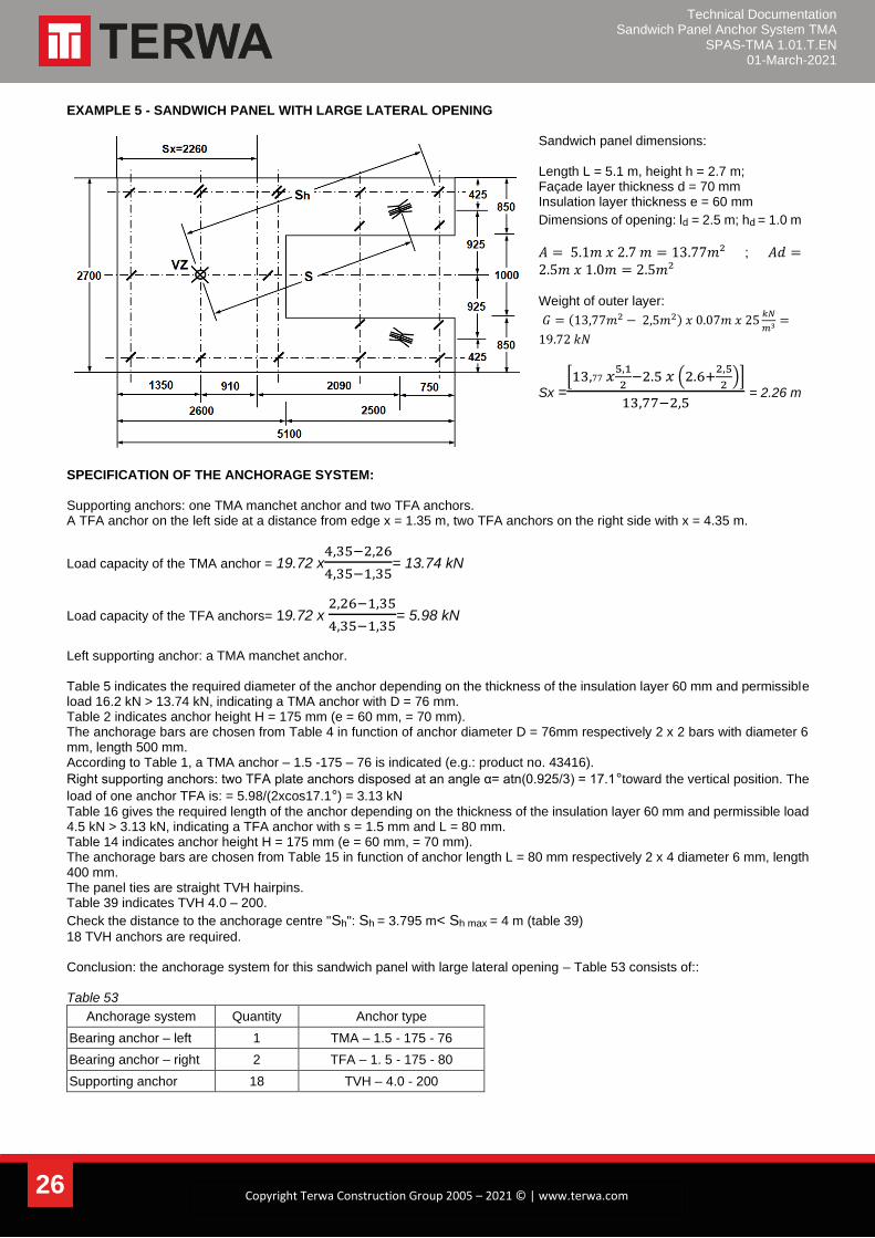
EXAMPLE 5 - SANDWICH PANEL WITH LARGE LATERAL OPENING
Sandwich panel dimensions: Length L = 5.1 m, height h = 2.7 m; Façade layer thickness d = 70 mm Insulation layer thickness e = 60 mm
Dimensions of opening: ld = 2.5 m; hd = 1.0 m
𝐴 = 5.1𝑚 𝑥 2.7 𝑚 = 13.77𝑚² ; 𝐴𝑑 =2.5𝑚 𝑥 1.0𝑚 = 2.5𝑚² Weight of outer layer:
𝐺 = (13,77𝑚2 − 2,5𝑚2) 𝑥 0.07𝑚 𝑥 25𝑘𝑁
𝑚3=
19.72 𝑘𝑁
Sx =[13,77 𝑥
5,1
2−2.5 𝑥 (2.6+
2,5
2)]
13,77−2,5 = 2.26 m
SPECIFICATION OF THE ANCHORAGE SYSTEM: Supporting anchors: one TMA manchet anchor and two TFA anchors. A TFA anchor on the left side at a distance from edge x = 1.35 m, two TFA anchors on the right side with x = 4.35 m.
Load capacity of the TMA anchor = 19.72 x4,35−2,26
4,35−1,35= 13.74 kN
Load capacity of the TFA anchors= 19.72 x 2,26−1,35
4,35−1,35= 5.98 kN
Left supporting anchor: a TMA manchet anchor. Table 5 indicates the required diameter of the anchor depending on the thickness of the insulation layer 60 mm and permissible load 16.2 kN > 13.74 kN, indicating a TMA anchor with D = 76 mm. Table 2 indicates anchor height H = 175 mm (e = 60 mm, = 70 mm). The anchorage bars are chosen from Table 4 in function of anchor diameter D = 76mm respectively 2 x 2 bars with diameter 6 mm, length 500 mm. According to Table 1, a TMA anchor – 1.5 -175 – 76 is indicated (e.g.: product no. 43416).
Right supporting anchors: two TFA plate anchors disposed at an angle α= atn(0.925/3) = 17.1°toward the vertical position. The
load of one anchor TFA is: = 5.98/(2xcos17.1°) = 3.13 kN
Table 16 gives the required length of the anchor depending on the thickness of the insulation layer 60 mm and permissible load 4.5 kN > 3.13 kN, indicating a TFA anchor with s = 1.5 mm and L = 80 mm. Table 14 indicates anchor height H = 175 mm (e = 60 mm, = 70 mm). The anchorage bars are chosen from Table 15 in function of anchor length L = 80 mm respectively 2 x 4 diameter 6 mm, length 400 mm. The panel ties are straight TVH hairpins. Table 39 indicates TVH 4.0 – 200.
Check the distance to the anchorage centre "Sh": Sh = 3.795 m< Sh max = 4 m (table 39)
18 TVH anchors are required. Conclusion: the anchorage system for this sandwich panel with large lateral opening – Table 53 consists of:: Table 53
Anchorage system Quantity Anchor type
Bearing anchor – left 1 TMA – 1.5 - 175 - 76
Bearing anchor – right 2 TFA – 1. 5 - 175 - 80
Supporting anchor 18 TVH – 4.0 - 200
Technical Documentation Sandwich Panel Anchor System TMA
SPAS-TMA 1.01.T.EN 01-March-2021
27 Copyright Terwa Construction Group 2005 – 2021 © | www.terwa.com
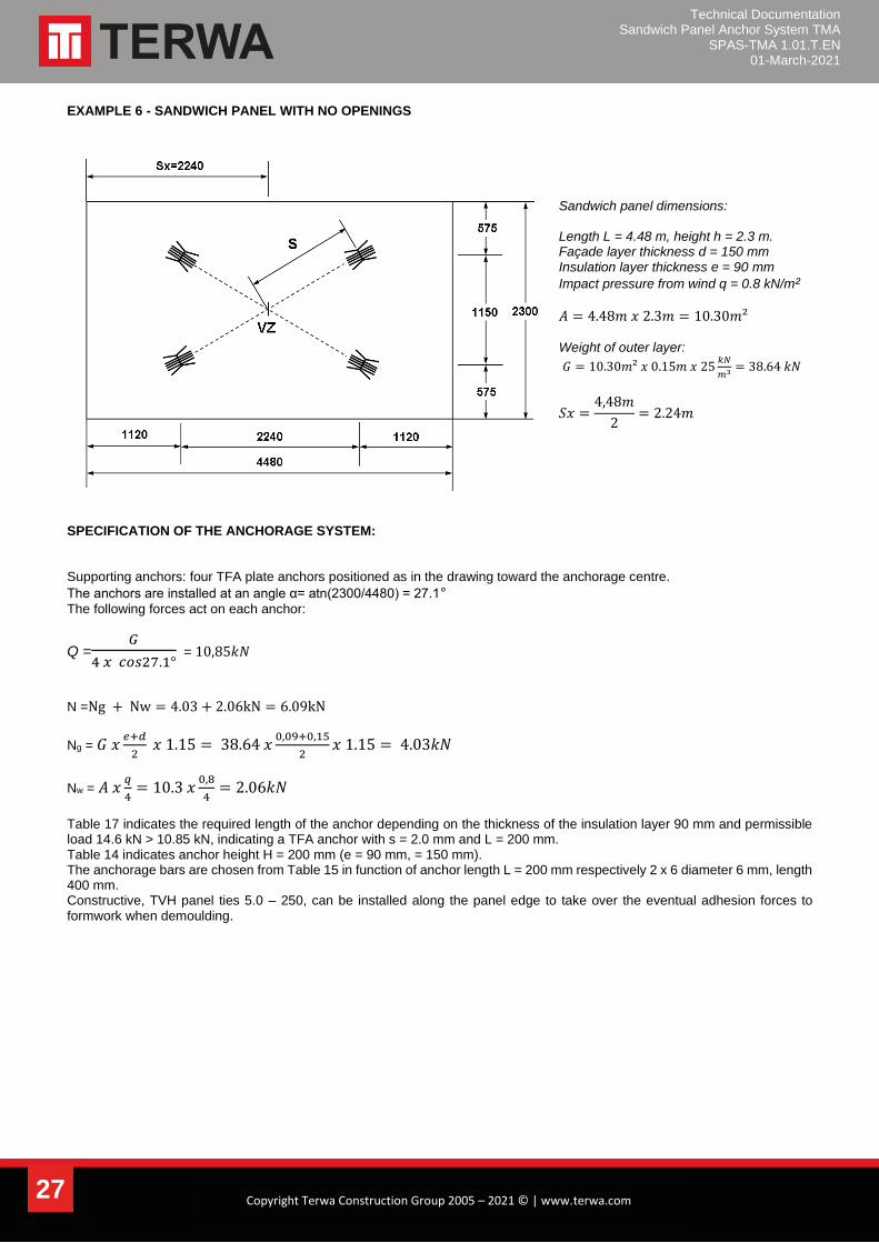
EXAMPLE 6 - SANDWICH PANEL WITH NO OPENINGS
Sandwich panel dimensions: Length L = 4.48 m, height h = 2.3 m. Façade layer thickness d = 150 mm Insulation layer thickness e = 90 mm
Impact pressure from wind q = 0.8 kN/m²
𝐴 = 4.48𝑚 𝑥 2.3𝑚 = 10.30𝑚²
Weight of outer layer:
𝐺 = 10.30𝑚² 𝑥 0.15𝑚 𝑥 25𝑘𝑁
𝑚3 = 38.64 𝑘𝑁
𝑆𝑥 =4,48𝑚
2= 2.24𝑚
SPECIFICATION OF THE ANCHORAGE SYSTEM: Supporting anchors: four TFA plate anchors positioned as in the drawing toward the anchorage centre.
The anchors are installed at an angle α= atn(2300/4480) = 27.1°
The following forces act on each anchor:
Q =𝐺
4 𝑥 𝑐𝑜𝑠27.1° = 10,85𝑘𝑁
N =Ng + Nw = 4.03 + 2.06kN = 6.09kN
Ng = 𝐺 𝑥𝑒+𝑑
2 𝑥 1.15 = 38.64 𝑥
0,09+0,15
2𝑥 1.15 = 4.03𝑘𝑁
Nw = 𝐴 𝑥𝑞
4= 10.3 𝑥
0,8
4= 2.06𝑘𝑁
Table 17 indicates the required length of the anchor depending on the thickness of the insulation layer 90 mm and permissible load 14.6 kN > 10.85 kN, indicating a TFA anchor with s = 2.0 mm and L = 200 mm. Table 14 indicates anchor height H = 200 mm (e = 90 mm, = 150 mm). The anchorage bars are chosen from Table 15 in function of anchor length L = 200 mm respectively 2 x 6 diameter 6 mm, length 400 mm. Constructive, TVH panel ties 5.0 – 250, can be installed along the panel edge to take over the eventual adhesion forces to formwork when demoulding.
Technical Documentation Sandwich Panel Anchor System TMA
SPAS-TMA 1.01.T.EN 01-March-2021
28 Copyright Terwa Construction Group 2005 – 2021 © | www.terwa.com
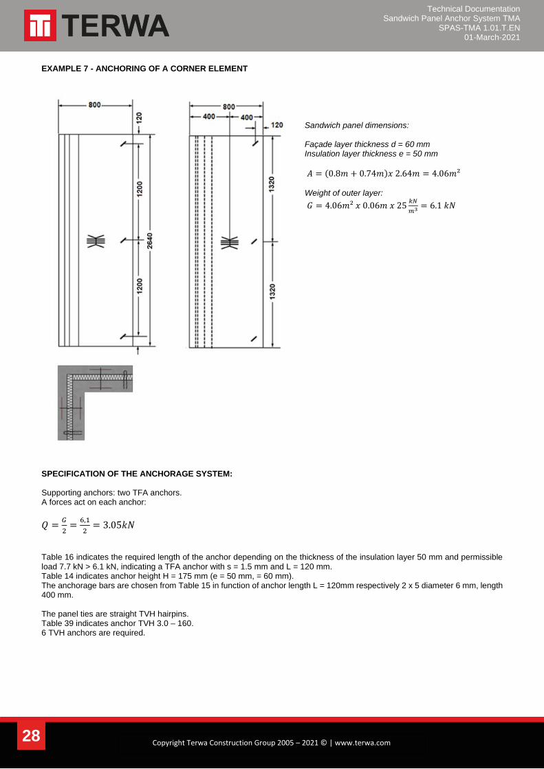
EXAMPLE 7 - ANCHORING OF A CORNER ELEMENT
Sandwich panel dimensions: Façade layer thickness d = 60 mm Insulation layer thickness e = 50 mm
𝐴 = (0.8𝑚 + 0.74𝑚)𝑥 2.64𝑚 = 4.06𝑚² Weight of outer layer:
𝐺 = 4.06𝑚² 𝑥 0.06𝑚 𝑥 25𝑘𝑁
𝑚3 = 6.1 𝑘𝑁
SPECIFICATION OF THE ANCHORAGE SYSTEM: Supporting anchors: two TFA anchors. A forces act on each anchor:
𝑄 =𝐺
2=
6,1
2= 3.05𝑘𝑁
Table 16 indicates the required length of the anchor depending on the thickness of the insulation layer 50 mm and permissible load 7.7 kN > 6.1 kN, indicating a TFA anchor with s = 1.5 mm and L = 120 mm. Table 14 indicates anchor height H = 175 mm (e = 50 mm, = 60 mm). The anchorage bars are chosen from Table 15 in function of anchor length L = 120mm respectively 2 x 5 diameter 6 mm, length 400 mm. The panel ties are straight TVH hairpins. Table 39 indicates anchor TVH 3.0 – 160. 6 TVH anchors are required.
Technical Documentation Sandwich Panel Anchor System TMA
SPAS-TMA 1.01.T.EN 01-March-2021
29 Copyright Terwa Construction Group 2005 – 2021 © | www.terwa.com
CONTACT
TERWA is the global supplier for precast and construction solutions with multiple offices around the world. With all our staff, partners and agents, we are happy to provide all construction and precast companies who work in the building industry with full service and 100% support. TERWA CONSTRUCTION GROUP
Terwa Construction Netherlands (HQ) Global Sales & Distribution
Kamerlingh Onneslaan 1-3 3401 MZ IJsselstein The Netherlands T +31-(0)30 699 13 29 F +31-(0)30 220 10 77 E [email protected]
Terwa Construction Central East Europe Sales & Distribution
Strada Sânzienei 507075 Ghimbav Romania T +40 372 611 576 E [email protected]
Terwa Construction Poland Sales & Distribution
Ul. Cicha 5 lok. 4 00-353 Warszawa Poland E [email protected]
Terwa Construction India & Middle East Sales & Distribution
India T +91 89 687 000 41 E [email protected]
Terwa Construction China Sales & distribution
5F 504, No. 101 Chuanchang road PRC, 200032, Shanghai China E [email protected]
ALL SPECIFICATIONS CAN BE CHANGED WITHOUT PREVIOUS NOTICE.
DISCLAIMER Terwa B.V. is not liable for deviations due to wear of the products it has delivered. Neither is Terwa B.V. liable for damage due to inaccurate and/or improper handling and use of the products it has delivered and/or use of same for purposes other than those intended. Terwa B.V.’s responsibility is furthermore limited in accordance with article 13 of the “Metaalunie” conditions, which are applicable for all Terwa B.V. deliveries. The user is responsible for ensuring compliance with all applicable copyright laws. Without limiting the rights under copyright, no part of this documentation may be reproduced, stored in or introduced into a retrieval system, or transmitted in any form or by any means (electronic, mechanical, photocopying, recording, or otherwise), or for any purpose, without the express written permission of Terwa B.V.