Embed Size (px)
Citation preview

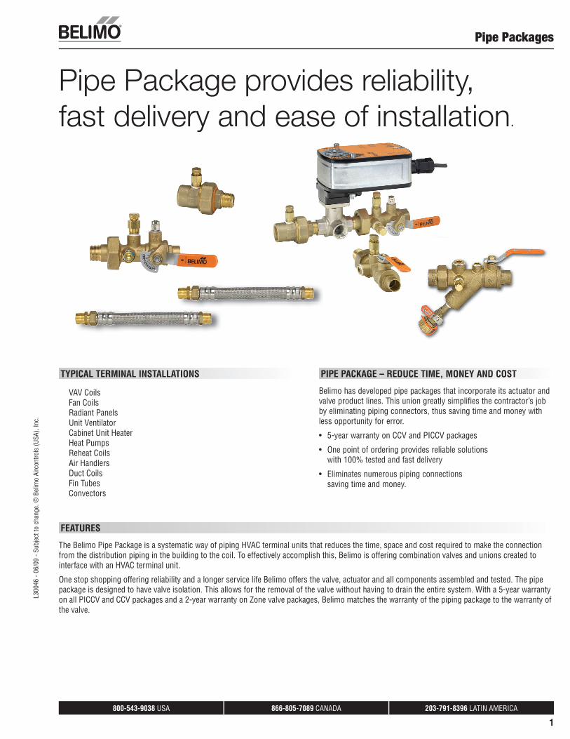
Technical Documentation Pipe PackagesEffective June 2009
Belim
o Pr
ojec
t: Ne
w C
astle
Cou
nty
Cour
thou
se, W
ilmin
gton
, DE
800-543-9038 USA 866-805-7089 CANADA 203-791-8396 LATIN AMERICA
1
FEATURES
The Belimo Pipe Package is a systematic way of piping HVAC terminal units that reduces the time, space and cost required to make the connection from the distribution piping in the building to the coil. To effectively accomplish this, Belimo is offering combination valves and unions created to interface with an HVAC terminal unit.
One stop shopping offering reliability and a longer service life Belimo offers the valve, actuator and all components assembled and tested. The pipe package is designed to have valve isolation. This allows for the removal of the valve without having to drain the entire system. With a 5-year warranty on all PICCV and CCV packages and a 2-year warranty on Zone valve packages, Belimo matches the warranty of the piping package to the warranty of the valve.
TYPICAL TERMINAL INSTALLATIONS
VAV CoilsFan CoilsRadiant PanelsUnit VentilatorCabinet Unit HeaterHeat PumpsReheat CoilsAir HandlersDuct CoilsFin TubesConvectors
Pipe Packages
Pipe Package provides reliability,fast delivery and ease of installation.
PIPE PACKAGE – REDUCE TIME, MONEY AND COST
Belimo has developed pipe packages that incorporate its actuator and valve product lines. This union greatly simplifies the contractor’s job by eliminating piping connectors, thus saving time and money with less opportunity for error.
• 5-year warranty on CCV and PICCV packages
• One point of ordering provides reliable solutionswith 100% tested and fast delivery
• Eliminates numerous piping connectionssaving time and money.
L300
46 -
06/0
9 - S
ubje
ct to
cha
nge.
© B
elim
o Ai
rcon
trols
(USA
), In
c.
800-543-9038 USA 866-805-7089 CANADA 203-791-8396 LATIN AMERICA
2
Feature / Benefi tsPipe Packages
Standard pipe packagesPICCV, CCV and Zone standard packages are available in ½”, ¾” and 1” sizes
Custom packages
PICCV and CCV are available in ½”, ¾”, 1”, 1¼”, 1½” and 2” sizes
Press fi ttings are available in ½” to 2” sizes
The Union, Isolation Valve and Strainer are available without a PT port
Unique versions are possible, call Belimo to speak to a factory expert for available options
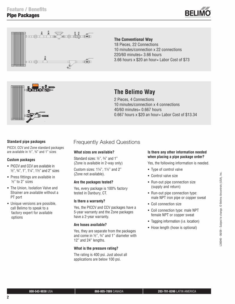
The Conventional Way 18 Pieces, 22 Connections10 minutes/connection x 22 connections220/60 minutes= 3.66 hours3.66 hours x $20 an hour= Labor Cost of $73
The Belimo Way 2 Pieces, 4 Connections10 minutes/connection x 4 connections40/60 minutes= 0.667 hours0.667 hours x $20 an hour= Labor Cost of $13.34
Frequently Asked Questions
What sizes are available?
Standard sizes: ½”, ¾” and 1”(Zone is available in 2-way only)
Custom sizes: 1¼”, 1½” and 2”(Zone not available).
Are the packages tested?
Yes, every package is 100% factory tested in Danbury, CT.
Is there a warranty?
Yes, the PICCV and CCV packages have a 5-year warranty and the Zone packages have a 2-year warranty.
Are hoses available?
Yes, they are separate from the packages and come in ½”, ¾” and 1” diameter with 12” and 24” lengths.
What is the pressure rating?
The rating is 400 psi. Just about all applications are below 100 psi.
Is there any other information needed when placing a pipe package order?
Yes, the following information is needed.
Type of control valve
Control valve size
Run-out pipe connection size (supply and return)
Run-out pipe connection type: male NPT iron pipe or copper sweat
Coil connection size
Coil connection type: male NPT female NPT or copper sweat
Tagging information (i.e. location)
Hose length (hose is optional)
SUPPLYSUPPLY
RETURNRETURN
A ABAB
L300
46 -
06/0
9 - S
ubje
ct to
cha
nge.
© B
elim
o Ai
rcon
trols
(USA
), In
c.
800-543-9038 USA 866-805-7089 CANADA 203-791-8396 LATIN AMERICA
3
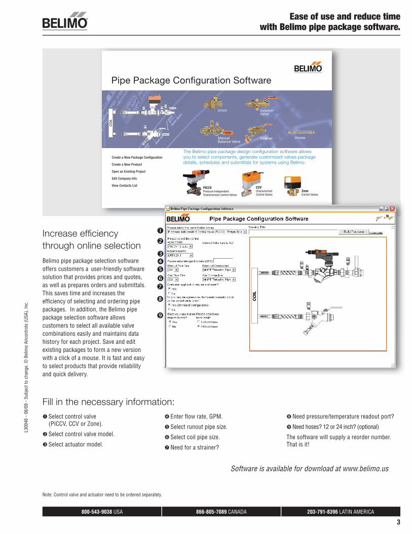
Increase effi ciency through online selection
Belimo pipe package selection software offers customers a user-friendly software solution that provides prices and quotes, as well as prepares orders and submittals. This saves time and increases the effi ciency of selecting and ordering pipe packages. In addition, the Belimo pipe package selection software allows customers to select all available valve combinations easily and maintains data history for each project. Save and edit existing packages to form a new version with a click of a mouse. It is fast and easy to select products that provide reliability and quick delivery.
Ease of use and reduce timewith Belimo pipe package software.
Pipe Package Confi guration Software
The Belimo pipe package design confi guration software allows
you to select components, generate customized valves package
details, schedules and submittals for systems using Belimo:
Strainer
Union Isolation Valve
Manual Balance Valve
Hoses
Create a New Package Confi guration
Create a New Product
Open an Existing Project
Edit Company Info
View Contacts ListPICCVPressure Independent Characterized Control Valves
CCVCharacterized Control Valves
Zone Control Valves
CO
IL
Select control valve(PICCV, CCV or Zone).
Select control valve model.
Select actuator model.
Enter fl ow rate, GPM.
Select runout pipe size.
Select coil pipe size.
Need for a strainer?
Need pressure/temperature readout port?
Need hoses? 12 or 24 inch? (optional)
The software will supply a reorder number. That is it!
Software is available for download at www.belimo.us
Fill in the necessary information:
Note: Control valve and actuator need to be ordered separately.
L300
46 -
06/0
9 - S
ubje
ct to
cha
nge.
© B
elim
o Ai
rcon
trols
(USA
), In
c.

This pageintentionally left blank.
800-543-9038 USA 866-805-7089 CANADA 203-791-8396 LATIN AMERICA
5
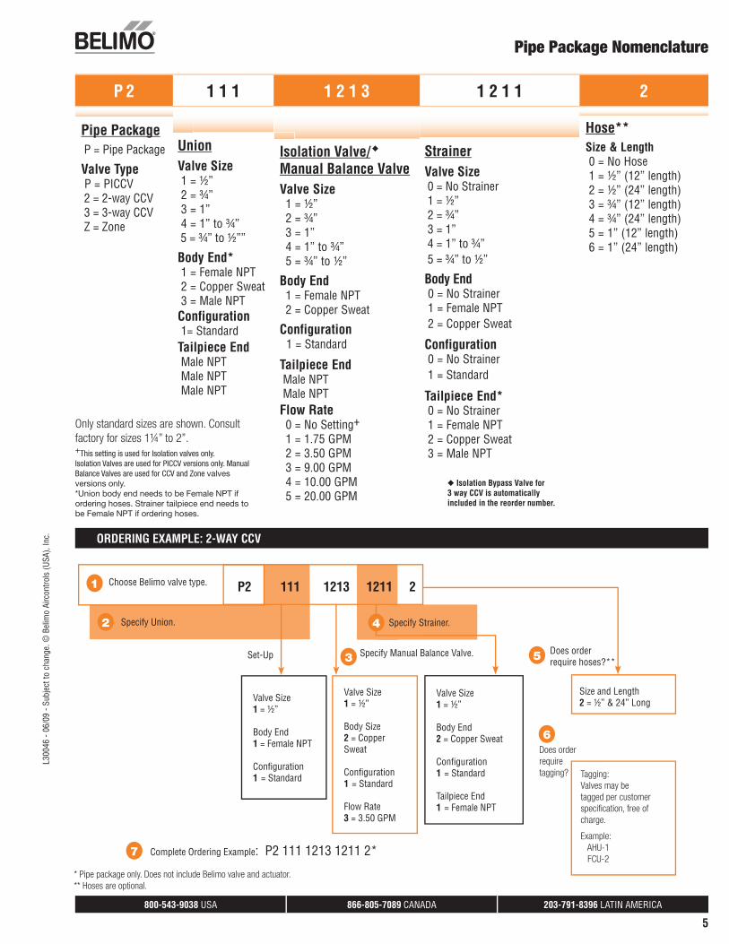
Pipe Package Nomenclature
2
1 Choose Belimo valve type. P2 111 1213 1211 2
Specify Union.
Specify Manual Balance Valve. 3
Valve Size1 = ½”
Body End1 = Female NPT
Confi guration1 = Standard
Set-Up
7 Complete Ordering Example: P2 111 1213 1211 2*
Valve Size1 = ½”
Body Size2 = Copper Sweat
Confi guration1 = Standard
Flow Rate3 = 3.50 GPM
Valve Size1 = ½”
Body End2 = Copper Sweat
Confi guration1 = Standard
Tailpiece End1 = Female NPT
4 Specify Strainer.
Does order require hoses?** 5
Size and Length 2 = ½” & 24” Long
Does order
require
tagging?
6
Tagging:
Valves may be
tagged per customer
specifi cation, free of
charge.
Example:
AHU-1
FCU-2
Only standard sizes are shown. Consult factory for sizes 1¼” to 2”.+This setting is used for Isolation valves only.Isolation Valves are used for PICCV versions only. Manual Balance Valves are used for CCV and Zone valves versions only.*Union body end needs to be Female NPT if ordering hoses. Strainer tailpiece end needs to be Female NPT if ordering hoses.
* Pipe package only. Does not include Belimo valve and actuator.** Hoses are optional.
ORDERING EXAMPLE: 2-WAY CCV
◆ Isolation Bypass Valve for3 way CCV is automaticallyincluded in the reorder number.
◆
P 2 1 1 1 1 2 1 3 1 2 1 1 2
Pipe Package P = Pipe Package
Valve Type P = PICCV 2 = 2-way CCV 3 = 3-way CCV Z = Zone
UnionValve Size 1 = ½” 2 = ¾” 3 = 1” 4 = 1” to ¾” 5 = ¾” to ½””
Body End* 1 = Female NPT 2 = Copper Sweat 3 = Male NPTConfiguration 1= StandardTailpiece End Male NPT Male NPT Male NPT
Isolation Valve/Manual Balance ValveValve Size 1 = ½” 2 = ¾” 3 = 1” 4 = 1” to ¾” 5 = ¾” to ½”
Body End 1 = Female NPT 2 = Copper Sweat
Configuration 1 = Standard
Tailpiece End Male NPT Male NPTFlow Rate 0 = No Setting+ 1 = 1.75 GPM 2 = 3.50 GPM 3 = 9.00 GPM 4 = 10.00 GPM 5 = 20.00 GPM
StrainerValve Size 0 = No Strainer 1 = ½” 2 = ¾” 3 = 1” 4 = 1” to ¾” 5 = ¾” to ½”
Body End 0 = No Strainer 1 = Female NPT 2 = Copper Sweat
Configuration 0 = No Strainer 1 = Standard
Tailpiece End* 0 = No Strainer 1 = Female NPT 2 = Copper Sweat 3 = Male NPT
Hose**
Size & Length 0 = No Hose 1 = ½” (12” length) 2 = ½” (24” length) 3 = ¾” (12” length) 4 = ¾” (24” length) 5 = 1” (12” length) 6 = 1” (24” length)
L300
46 -
06/0
9 - S
ubje
ct to
cha
nge.
© B
elim
o Ai
rcon
trols
(USA
), In
c.
800-543-9038 USA 866-805-7089 CANADA 203-791-8396 LATIN AMERICA
6
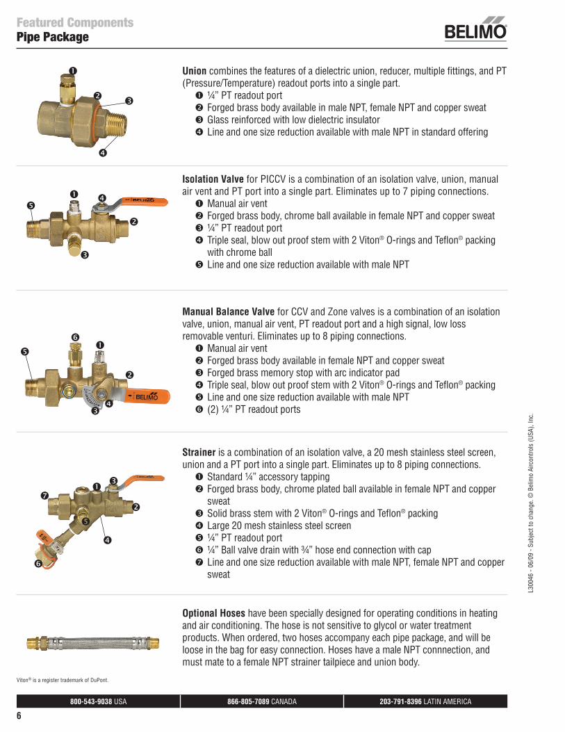
Featured ComponentsPipe Package
Union combines the features of a dielectric union, reducer, multiple fi ttings, and PT (Pressure/Temperature) readout ports into a single part.
¼” PT readout port Forged brass body available in male NPT, female NPT and copper sweat Glass reinforced with low dielectric insulator Line and one size reduction available with male NPT in standard offering
Isolation Valve for PICCV is a combination of an isolation valve, union, manual air vent and PT port into a single part. Eliminates up to 7 piping connections.
Manual air vent Forged brass body, chrome ball available in female NPT and copper sweat ¼” PT readout port Triple seal, blow out proof stem with 2 Viton® O-rings and Tefl on® packing with chrome ball
Line and one size reduction available with male NPT
Manual Balance Valve for CCV and Zone valves is a combination of an isolation valve, union, manual air vent, PT readout port and a high signal, low loss removable venturi. Eliminates up to 8 piping connections.
Manual air vent Forged brass body available in female NPT and copper sweat Forged brass memory stop with arc indicator pad Triple seal, blow out proof stem with 2 Viton® O-rings and Tefl on® packing Line and one size reduction available with male NPT (2) ¼” PT readout ports
Strainer is a combination of an isolation valve, a 20 mesh stainless steel screen, union and a PT port into a single part. Eliminates up to 8 piping connections.
Standard ¼” accessory tapping Forged brass body, chrome plated ball available in female NPT and copper sweat
Solid brass stem with 2 Viton® O-rings and Tefl on® packing Large 20 mesh stainless steel screen ¼” PT readout port ¼” Ball valve drain with ¾” hose end connection with cap Line and one size reduction available with male NPT, female NPT and copper sweat
Optional Hoses have been specially designed for operating conditions in heating and air conditioning. The hose is not sensitive to glycol or water treatment products. When ordered, two hoses accompany each pipe package, and will be loose in the bag for easy connection. Hoses have a male NPT connnection, and must mate to a female NPT strainer tailpiece and union body.
Viton® is a register trademark of DuPont.
L300
46 -
06/0
9 - S
ubje
ct to
cha
nge.
© B
elim
o Ai
rcon
trols
(USA
), In
c.
800-543-9038 USA 866-805-7089 CANADA 203-791-8396 LATIN AMERICA
7
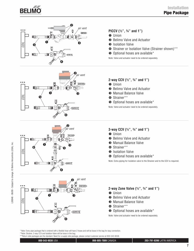
InstallationPipe Package
PICCV (½”, ¾” and 1”) Union Belimo Valve and Actuator Isolation Valve Strainer or Isolation Valve (Strainer shown)** Optional hoses are available*
Note: Valve and actuator need to be ordered separately.
2-way CCV (½”, ¾” and 1”) Union Belimo Valve and Actuator Manual Balance Valve Strainer** Optional hoses are available*
Note: Valve and actuator need to be ordered separately.
3-way CCV (½”, ¾” and 1”) Union Belimo Valve and Actuator Manual Balance Valve Strainer** Isolation Valve Optional hoses are available*
Note: Extra piping for Isolation valve to the Strainer and to the CCV is required.
2-way Zone Valve (½”, ¾” and 1”) Union Belimo Valve and Actuator Manual Balance Valve Strainer** Optional hoses are available*
Note: Valve and actuator need to be ordered separately.
COIL
COIL
COIL
COIL
air vent
air vent
air vent
air vent
* Note: Every pipe package that is ordered with a flexible hose will have 2 hoses and will be loose in the bag for easy connection. **Note: Strainer, 3-way CCV and Isolation Valve will be loose in the bag.***Return side packages are the standard. Need for a supply side package, please contact customer service at 800-543-9038.
***
***
***
***
L300
46 -
06/0
9 - S
ubje
ct to
cha
nge.
© B
elim
o Ai
rcon
trols
(USA
), In
c.
800-543-9038 USA 866-805-7089 CANADA 203-791-8396 LATIN AMERICA
8
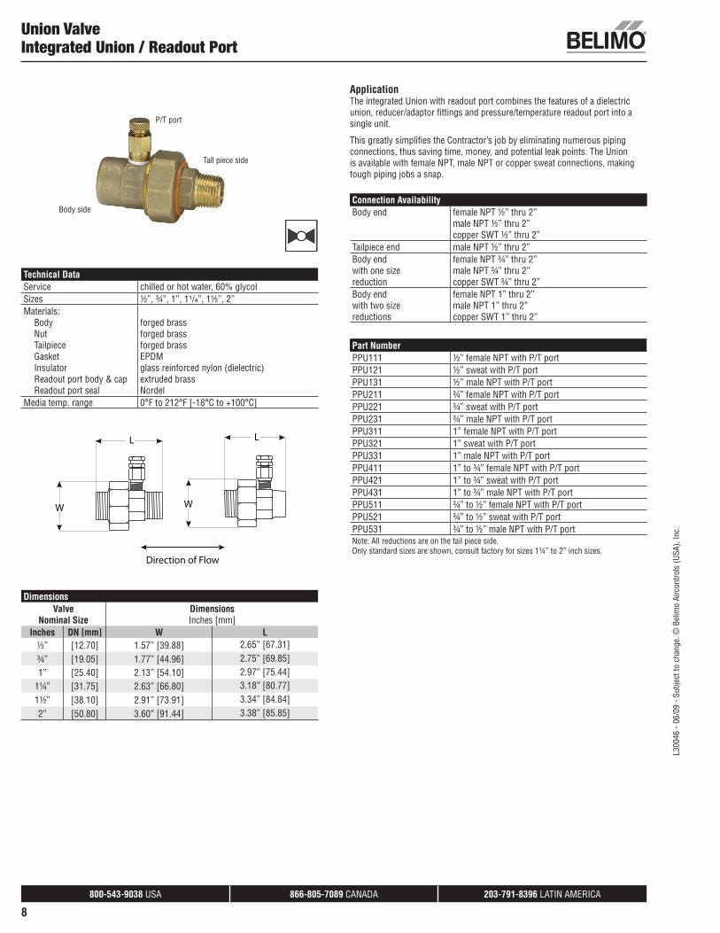
Union ValveIntegrated Union / Readout Port
Technical DataService chilled or hot water, 60% glycolSizes ½”, ¾”, 1”, 1¹/₄”, 1½”, 2”Materials:
BodyNutTailpieceGasketInsulatorReadout port body & capReadout port seal
forged brassforged brassforged brassEPDMglass reinforced nylon (dielectric)extruded brassNordel
Media temp. range 0°F to 212°F [-18°C to +100°C]
W
L
W
L
Direction of Flow
DimensionsValve
Nominal SizeDimensionsInches [mm]
Inches DN [mm] W L½” [12.70] 1.57” [39.88] 2.65” [67.31]¾” [19.05] 1.77” [44.96] 2.75” [69.85]1” [25.40] 2.13” [54.10] 2.97” [75.44]
1¼” [31.75] 2.63” [66.80] 3.18” [80.77]1½” [38.10] 2.91” [73.91] 3.34” [84.84]2” [50.80] 3.60” [91.44] 3.38” [85.85]
ApplicationThe integrated Union with readout port combines the features of a dielectric union, reducer/adaptor fi ttings and pressure/temperature readout port into a single unit.
This greatly simplifi es the Contractor’s job by eliminating numerous piping connections, thus saving time, money, and potential leak points. The Union is available with female NPT, male NPT or copper sweat connections, making tough piping jobs a snap.
Connection AvailabilityBody end female NPT ½” thru 2”
male NPT ½” thru 2” copper SWT ½” thru 2”
Tailpiece end male NPT ½” thru 2”Body endwith one sizereduction
female NPT ¾” thru 2”male NPT ¾” thru 2”copper SWT ¾” thru 2”
Body endwith two sizereductions
female NPT 1” thru 2”male NPT 1” thru 2”copper SWT 1” thru 2”
Part NumberPPU111 ½” female NPT with P/T portPPU121 ½” sweat with P/T portPPU131 ½” male NPT with P/T portPPU211 ¾” female NPT with P/T portPPU221 ¾” sweat with P/T portPPU231 ¾” male NPT with P/T portPPU311 1” female NPT with P/T portPPU321 1” sweat with P/T portPPU331 1” male NPT with P/T portPPU411 1” to ¾” female NPT with P/T portPPU421 1” to ¾” sweat with P/T portPPU431 1” to ¾” male NPT with P/T portPPU511 ¾” to ½” female NPT with P/T portPPU521 ¾” to ½” sweat with P/T portPPU531 ¾” to ½” male NPT with P/T portNote: All reductions are on the tail piece side.Only standard sizes are shown, consult factory for sizes 1¼” to 2” inch sizes.
P/T port
Tail piece side
Body side
L300
46 -
06/0
9 - S
ubje
ct to
cha
nge.
© B
elim
o Ai
rcon
trols
(USA
), In
c.
800-543-9038 USA 866-805-7089 CANADA 203-791-8396 LATIN AMERICA
9
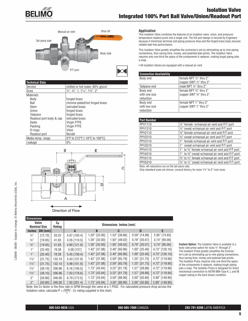
Isolation ValveIntegrated 100% Port Ball Valve/Union/Readout Port
Custom Option: The Isolation Valve is available in a body side press option for sizes ½” through 2”. The Isolation Press greatly simplifi es the Contrac-tor’s job by eliminating up to nine piping connections, thus saving time, money and potenial leak points. The Isolation Press requires only one third the space of the components it replaces, making tough piping jobs a snap. The Isolation Press is designed for direct mechanical connection to ASTM B88-Type K, L and M copper tubing in the hard drawn condition.
Manual air vent Shut off
Body side
P/T port
Tail piece side
ApplicationThis Isolation Valve combines the features of an isolation valve, union, and pressure/temperature readout ports into a single unit. The full port design is favored by Engineers because it minimizes terminal unit piping pressure drop and the forged brass body ensures reliable leak-free performance.
This Isolation Valve greatly simplifi es the contractor’s job by eliminating up to nine piping connections, thus saving time, money, and potential leak points. The Isolation Valve requires only one third the space of the components it replaces, making tough piping jobs a snap.
• All Isolation Valves are equipped with a manual air vent.
Connection AvailabilityBody end female NPT ½” thru 2”
copper SWT ½” thru 2”Tailpiece end male NPT ½” thru 2”Body endwith one sizereduction
female NPT ¾” thru 2”copper SWT ¾” thru 2”
Body endwith two sizereduction
female NPT 1” thru 2”copper SWT 1” thru 2”
Part NumberPPV1110 ½” female w/manual air vent and P/T portPPV1210 ½” sweat w/manual air vent and P/T portPPV2110 ¾” female w/manual air vent and P/T portPPV2210 ¾” sweat w/manual air vent and P/T portPPV3110 1” female w/manual air vent and P/T port PPV3210 1” sweat w/manual air vent and P/T portPPV4110 1” to ¾” female w/manual air vent and P/T port PPV4210 1” to ¾” sweat w/manual air vent and P/T portPPV5110 ¾” to ½” female w/manual air vent and P/T port PPV5210 ¾” to ½” sweat w/manual air vent and P/T portNote: All reductions are on the tail piece side.Only standard sizes are shown, consult factory for sizes 1¼” to 2” inch sizes.
Technical DataService chilled or hot water, 60% glycolSizes ½”, ¾”, 1, 1¹/₄”, 1½”, 2”Materials:
BodyBallStemUnionTailpieceReadout port body & capSeatsPackingO-ringsReadout port
forged brasschrome plated/hot forged brassextruded brassforged brassforged brassextruded brassVirgin PTFEVirgin PTFEVitonNordel
Media temp. range 0°F to 212°F [-18°C to 100°C]Leakage 0%
� ������³
Direction of Flow
DimensionsValve
Nominal SizeCv
Rating Dimensions Inches [mm]
Inches DN [mm] A B C D E½” [12.70] 20.25 4.07 [103.4] 1,26” [32.00] 1.53” [38.86] 0.59” [14.99] 2.95” [74.93]¾” [19.05] 41.83 4.35 [110.5] 1.26” [32.00] 1.93” [49.02] 0.79” [20.07] 3.74” [95.00]¾” [19.05] 41.83 4.80 [121.9] 1.26” [32.00] 1.93” [49.02] 0.79” [20.07] 3.74” [95.00]1” [25.40] 78.38 5.00 [127] 1.42” [37.08] 2.40” [60.96] 1.00” [25.40] 4.73” [120.10]1” [25.40] 78.38 5.45 [138.4] 1.42” [37.08] 2.40” [60.96] 1.00” [25.40] 4.73” [120.10]
1¼” [31.75] 132.10 5.43 [137.9] 1.42” [37.08] 2.59” [65.79] 1.25” [31.75] 4.72” [119.90]1¼” [31.75] 132.10 5.98 [151.9] 1.42” [37.08] 2.59” [65.79] 1.25” [31.75] 4.72” [119.90]1½” [38.10] 206.96 6.16 [156.5] 1.73” [43.94] 3.22” [81.79] 1.57” [39.88] 4.72” [119.90]1½” [38.10] 206.96 7.03 [178.6] 1.73” [43.94] 3.22” [81.79] 1.57” [39.88] 4.72” [119.90]2” [50.80] 346.00 6.79 [172.5] 1.73” [43.94] 3.50” [88.90] 2.00” [50.80] 5.90” [149.90]2” [50.80] 346.00 7.93 [201.4] 1.73” [43.94] 3.50” [88.90] 2.00” [50.80] 5.90” [149.90]
Note: the Cv factor is the fl ow rate in GPM through the valve at a 1 PSID. For calculated pressure drop across the Isolation valve, calculate P = (GPM)2 . Cv rating supplied in the chart.
Cv
L300
46 -
06/0
9 - S
ubje
ct to
cha
nge.
© B
elim
o Ai
rcon
trols
(USA
), In
c.
800-543-9038 USA 866-805-7089 CANADA 203-791-8396 LATIN AMERICA
10
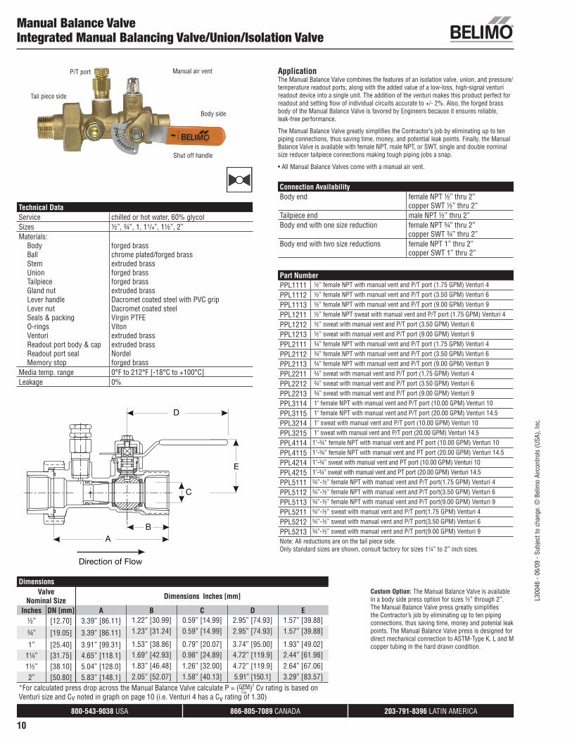
Manual Balance ValveIntegrated Manual Balancing Valve/Union/Isolation Valve
Technical DataService chilled or hot water, 60% glycolSizes ½”, ¾”, 1, 1¹/₄”, 1½”, 2”Materials:
BodyBallStem UnionTailpieceGland nutLever handleLever nutSeals & packingO-ringsVenturiReadout port body & capReadout port sealMemory stop
forged brasschrome plated/forged brassextruded brassforged brassforged brassextruded brassDacromet coated steel with PVC gripDacromet coated steelVirgin PTFEVitonextruded brassextruded brassNordelforged brass
Media temp. range 0°F to 212°F [-18°C to +100°C]Leakage 0%
A
D
E
B
C
Direction of Flow
DimensionsValve
Nominal Size Dimensions Inches [mm]
Inches DN [mm] A B C D E½” [12.70] 3.39” [86.11] 1.22” [30.99] 0.59” [14.99] 2.95” [74.93] 1.57” [39.88]
¾” [19.05] 3.39” [86.11] 1.23” [31.24] 0.59” [14.99] 2.95” [74.93] 1.57” [39.88]
1” [25.40] 3.91” [99.31] 1.53” [38.86] 0.79” [20.07] 3.74” [95.00] 1.93” [49.02]1¼” [31.75] 4.65” [118.1] 1.69” [42.93] 0.98” [24.89] 4.72” [119.9] 2.44” [61.98]1½” [38.10] 5.04” [128.0] 1.83” [46.48] 1.26” [32.00] 4.72” [119.9] 2.64” [67.06]2” [50.80] 5.83” [148.1] 2.05” [52.07] 1.58” [40.13] 5.91” [150.1] 3.29” [83.57]
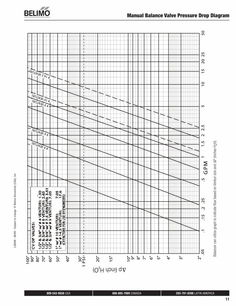
*For calculated press drop across the Manual Balance Valve calculate P = (GPM)2 Cv rating is based on Venturi size and Cv noted in graph on page 10 (i.e. Venturi 4 has a Cv rating of 1.30)
Custom Option: The Manual Balance Valve is available in a body side press option for sizes ½” through 2”. The Manual Balance Valve press greatly simplifies the Contractor’s job by eliminating up to ten piping connections, thus saving time, money and potenial leak points. The Manual Balance Valve press is designed for direct mechanical connection to ASTM-Type K, L and M copper tubing in the hard drawn condition.
Shut off handle
Manual air ventP/T port
Tail piece side
Body side
ApplicationThe Manual Balance Valve combines the features of an isolation valve, union, and pressure/temperature readout ports, along with the added value of a low-loss, high-signal venturi readout device into a single unit. The addition of the venturi makes this product perfect for readout and setting fl ow of individual circuits accurate to +/- 2%. Also, the forged brass body of the Manual Balance Valve is favored by Engineers because it ensures reliable, leak-free performance.
The Manual Balance Valve greatly simplifi es the Contractor’s job by eliminating up to ten piping connections, thus saving time, money, and potential leak points. Finally, the Manual Balance Valve is available with female NPT, male NPT, or SWT, single and double nominal size reducer tailpiece connections making tough piping jobs a snap.
• All Manual Balance Valves come with a manual air vent.
Connection AvailabilityBody end female NPT ½” thru 2”
copper SWT ½” thru 2”Tailpiece end male NPT ½” thru 2”Body end with one size reduction female NPT ¾” thru 2”
copper SWT ¾” thru 2”Body end with two size reductions female NPT 1” thru 2”
copper SWT 1” thru 2”
Part NumberPPL1111 ½” female NPT with manual vent and P/T port (1.75 GPM) Venturi 4
PPL1112 ½” female NPT with manual vent and P/T port (3.50 GPM) Venturi 6
PPL1113 ½” female NPT with manual vent and P/T port (9.00 GPM) Venturi 9
PPL1211 ½” female NPT sweat with manual vent and P/T port (1.75 GPM) Venturi 4
PPL1212 ½” sweat with manual vent and P/T port (3.50 GPM) Venturi 6
PPL1213 ½” sweat with manual vent and P/T port (9.00 GPM) Venturi 9
PPL2111 ¾” female NPT with manual vent and P/T port (1.75 GPM) Venturi 4
PPL2112 ¾” female NPT with manual vent and P/T port (3.50 GPM) Venturi 6
PPL2113 ¾” female NPT with manual vent and P/T port (9.00 GPM) Venturi 9
PPL2211 ¾” sweat with manual vent and P/T port (1.75 GPM) Venturi 4
PPL2212 ¾” sweat with manual vent and P/T port (3.50 GPM) Venturi 6
PPL2213 ¾” sweat with manual vent and P/T port (9.00 GPM) Venturi 9
PPL3114 1" female NPT with manual vent and P/T port (10.00 GPM) Venturi 10
PPL3115 1" female NPT with manual vent and P/T port (20.00 GPM) Venturi 14.5
PPL3214 1" sweat with manual vent and P/T port (10.00 GPM) Venturi 10
PPL3215 1" sweat with manual vent and P/T port (20.00 GPM) Venturi 14.5
PPL4114 1"-¾” female NPT with manual vent and PT port (10.00 GPM) Venturi 10
PPL4115 1"-¾” female NPT with manual vent and PT port (20.00 GPM) Venturi 14.5
PPL4214 1"-¾” sweat with manual vent and PT port (10.00 GPM) Venturi 10
PPL4215 1"-¾” sweat with manual vent and PT port (20.00 GPM) Venturi 14.5
PPL5111 ¾”-½” female NPT with manual vent and P/T port(1.75 GPM) Venturi 4
PPL5112 ¾”-½” female NPT with manual vent and P/T port(3.50 GPM) Venturi 6
PPL5113 ¾”-½” female NPT with manual vent and P/T port(9.00 GPM) Venturi 9
PPL5211 ¾”-½” sweat with manual vent and P/T port(1.75 GPM) Venturi 4
PPL5212 ¾”-½” sweat with manual vent and P/T port(3.50 GPM) Venturi 6
PPL5213 ¾”-½” sweat with manual vent and P/T port(9.00 GPM) Venturi 9Note: All reductions are on the tail piece side.Only standard sizes are shown, consult factory for sizes 1¼” to 2” inch sizes.
Cv
L300
46 -
06/0
9 - S
ubje
ct to
cha
nge.
© B
elim
o Ai
rcon
trols
(USA
), In
c.
800-543-9038 USA 866-805-7089 CANADA 203-791-8396 LATIN AMERICA
11
#9 VENTURI
#6 VENTURI
#10 VENTURI
#14.5 VENTURI
#4 VENTURI
.1.0
5
3''
5''
2''
4''
8''
7''
9''
10''
20''
15''
30''
1 P
SI
40''
50''
60''
80''
70''
90''
100'
'
6''
.15
.2.2
5.5
1.5
12
2.5
515
2025
5010
GP
M
CV
OF
VA
LVE
S:
.
1/2
'' &
3/4
'' w
/ #
4 V
EN
TU
RI:
1.3
01
/2''
& 3
/4''
w/
#6
VE
NT
UR
I: 2
.65
1/2
'' &
3/4
'' w
/ #
7.5
VE
NT
UR
I: 3
.61
1/2
'' &
3/4
'' w
/ #
9 V
EN
TU
RI:
7.0
5
1
'' w
/ #
10
VE
NT
UR
I:
7
.05
1''
w/
#1
4.5
VE
NT
UR
I:
17
.6(C
V FA
CTO
RS F
OR
USE
BY
ENG
INEE
RS)
vative hydronic c omponents a nd acc ess ories for the HVA C industry.Miller Dr. S uite 2 00 W arren, MI 48092 P hone: 1-800-313-HVA C F ax: 1 -86
Manual Balance Valve Pressure Drop Diagram
Bala
ncer
can
util
ize g
raph
to in
dica
te fl
ow b
ased
on
Vent
uri s
ize a
nd Δ
P (in
ches
H20
).
L300
46 -
06/0
9 - S
ubje
ct to
cha
nge.
© B
elim
o Ai
rcon
trols
(USA
), In
c.
800-543-9038 USA 866-805-7089 CANADA 203-791-8396 LATIN AMERICA
12
GP
M1
23
45
67
89
10
20
30
40
60
50
80
90
10
07
0
1
1"
2"
3"
4"
5"
6"
7"
8"
9"
10
"
20
"
30
"1
ps
i40
"
50
"
60
"
70
"8
0"
90
"1
00
"2
34
56
78
91
02
03
04
06
05
08
09
01
00
70
omponents and ac ce ss ories for the HVA C industry. 2 00 W arren, MI 48092 P hone: 1 -800-313-HVA C F ax : 1 -8
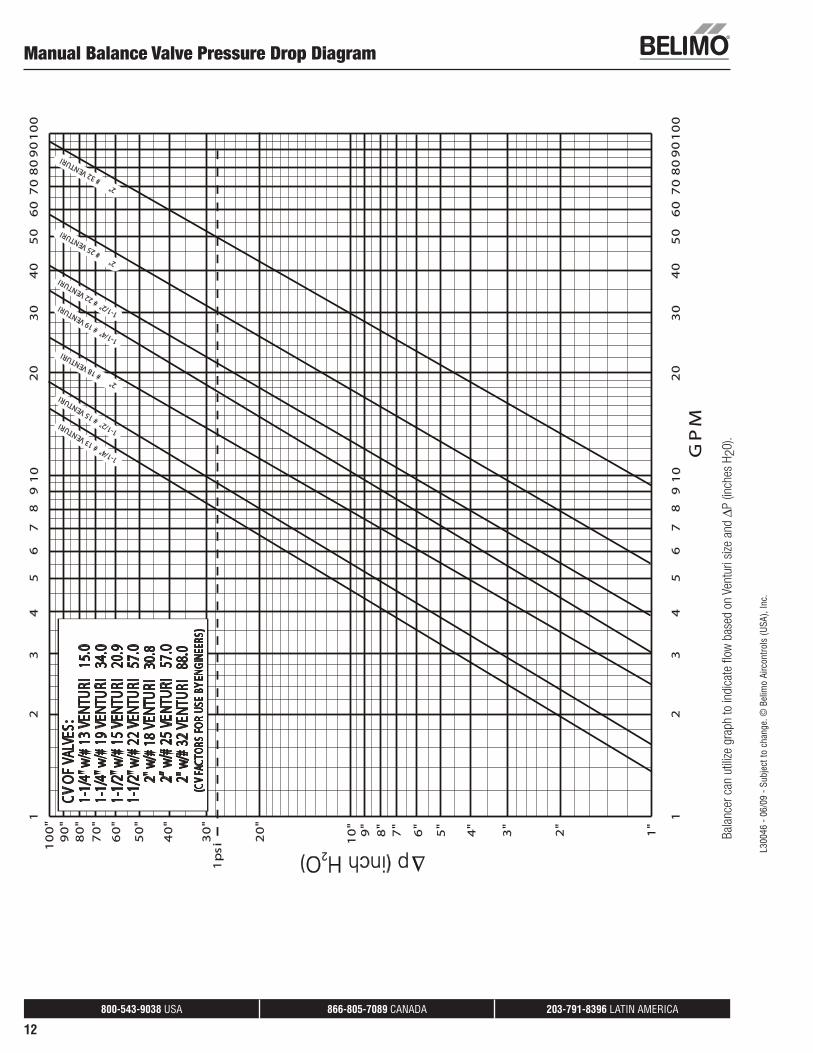
1-1/4" #13 VENTURI
1-1/2" #15 VENTURI
2" #
18 VENTURI
2" #
32 VENTURI
2" #
25 VENTURI
1-1/4" #19 VENTURI
1-1/2" #22 VENTURI
CV O
F VA
LVES
:1-
1/4"
w/#
13 V
ENTU
RI
15.0
1-1/
4" w
/#19
VEN
TURI
34
.01-
1/2"
w/#
15 V
ENTU
RI
20.9
1-1/
2" w
/#22
VEN
TURI
57
.0
2"
w/#
18 V
ENTU
RI
30.8
2" w
/#32
VEN
TURI
88
.0
2” w
/#25
VEN
TURI
57
.0
(CV
FACT
ORS
FOR
USE
BY E
NGIN
EERS
)
Manual Balance Valve Pressure Drop Diagram
Bala
ncer
can
util
ize g
raph
to in
dica
te fl
ow b
ased
on
Vent
uri s
ize a
nd Δ
P (in
ches
H20
).
L300
46 -
06/0
9 - S
ubje
ct to
cha
nge.
© B
elim
o Ai
rcon
trols
(USA
), In
c.
800-543-9038 USA 866-805-7089 CANADA 203-791-8396 LATIN AMERICA
13
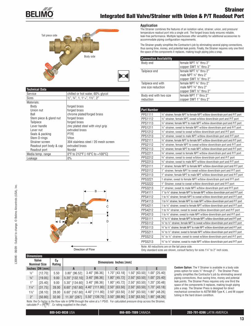
Tail piece side
Body side
StrainerIntegrated Ball Valve/Strainer with Union & P/T Readout Port
Technical DataService chilled or hot water, 60% glycolSizes ½”, ¾”, 1, 1¹/₄”, 1½”, 2”Materials:
BodyUnion nutBallStem piece & gland nutTailpieceLever handleLever nutSeals & packingStem O-ringsStrainer screenReadout port body & capReadout port
forged brassforged brasschrome plated/forged brassforged brassforged brasszinc plated steel with vinyl gripextruded brassPTFEViton304 stainless steel / 20 mesh screen extruded brassNordel
Media temp. range 0°F to 212°F [-18°C to +100°C]Leakage 0%
Custom Option: The Y Strainer is available in a body side press option for sizes ½” through 2”. The Strainer Press greatly simplifi es the Contractor’s job by eliminating several piping connections, thus saving time, money and potenial leak points. The Strainer Press requires only one third the space of the components it replaces, making tough piping jobs a snap. The Strainer Press is designed for direct mechanical connection to ASTM B88-Type K, L and M copper tubing in the hard drawn condition.
A
B
C
E D
Direction of Flow
ApplicationThe Strainer combines the features of an isolation valve, strainer, union, and pressure/temperature readout port into a single unit. The forged brass body ensures reliable, leak-free performance. Multiple taps/bosses offer versatility for additional accessories to accommodate piping confi guration requirements.
The Strainer greatly simplifi es the Contractor’s job by eliminating several piping connections, thus saving time, money, and potential leak points. Finally, the Strainer requires only one third the space of the components it replaces, making tough piping jobs a snap.
Connection AvailabilityBody end female NPT ½” thru 2”
copper SWT ½” thru 2”Tailpiece end female NPT ½” thru 2”
male NPT ½” thru 2”copper SWT ½” thru 2”
Tailpiece end withone size reduction
female NPT ¾” thru 2”male NPT ¾” thru 2”copper SWT ½” thru 2”
Body end with two size reduction
female NPT 1” thru 2”copper SWT 1” thru 2”
Part NumberPPS1111 ½” strainer, female NPT to female NPT w/blow down/drain port and P/T portPPS1112 ½” strainer, female NPT, sweat w/blow down/drain port and P/T port
PPS1113 ½” strainer, female NPT to male NPT w/blow down/drain port and P/T port
PPS1211 ½” strainer, sweat to female NPT w/blow down/drain port and P/T portPPS1212 ½” strainer, sweat to sweat w/blow down/drain port and P/T portPPS1213 ½” strainer, sweat to male NPT w/blow down/drain port and P/T portPPS2111 ¾” strainer, female NPT to female NPT w/blow down/drain port and P/T portPPS2112 ¾” strainer, female NPT to sweat w/blow down/drain port and P/T portPPS2113 ¾” strainer, female NPT to male NPT w/blow down/drain port and P/T portPPS2211 ¾” strainer, sweat to female NPT w/blow down/drain port and P/T portPPS2212 ¾” strainer, sweat to sweat w/blow down/drain port and P/T portPPS2213 ¾” strainer, sweat to male NPT w/blow down/drain port and P/T port
PPS3111 1” strainer, female NPT to female NPT w/blow down/drain port and P/T port
PPS3112 1” strainer, female NPT to sweat w/blow down/drain port and P/T portPPS3113 1” strainer, female NPT to male NPT w/blow down/drain port and P/T port
PPS3221 1 strainer, sweat to female NPT w/blow down/drain port and P/T port
PPS3222 1” Strainer, sweat to sweat w/blow down/drain port and P/T port
PPS3213 1” strainer, sweat to male NPT w/blow down/drain port and P/T port
PPS4111 1” to ¾” strainer, female NPT to female NPT w/blow down/drain port and P/T port
PPS4112 1 to ¾” strainer, female NPT to sweat w/blow down/drain port and P/T port
PPS4113 1 to ¾” strainer, female NPT to male NPT w/blow down/drain port and P/T port
PPS4211 1 to ¾” strainer, sweat to female NPT w/blow down/drain port and P/T port
PPS4212 1 to ¾” strainer, sweat to sweat w/blow down/drain port and P/T port
PPS4213 1 to ¾” strainer, sweat to male NPT w/blow down/drain port and P/T portPPS5111 ¾” to ½” strainer, female NPT to female NPT w/blow down/drain port and P/T portPPS5112 ¾” to ½” strainer, female NPT to sweat w/blow down/drain port and P/T port
PPS5113 ¾” to ½” strainer, female NPT to male NPT w/blow down/drain port and P/T port
PPS5211 ¾” to ½” strainer, sweat to female NPT w/blow down/drain port and P/T port
PPS5212 ¾” to ½” strainer, sweat to sweat w/blow down/drain port and P/T port
PPS5213 ¾” to ½” strainer, sweat to male NPT w/blow down/drain port and P/T port
Note: All reductions are on the tail piece side.Only standard sizes are shown, consult factory for sizes 1¼” to 2” inch sizes.
DimensionsValve
Nominal SizeCv
Rating Dimensions Inches [mm]
Inches DN [mm] A B C D E½” [12.70] 5.50 3.80” [96.52] 3.40” [86.36] 1.70” [43.18] 1.50” [63.50] 1.00” [25.40]¾” [19.05] 9.00 5.20” [132.10] 3.40” [86.36] 1.80” [45.72] 2.50” [63.50] 1.00” [25.40]1” [25.40] 9.00 5.30” [134.60] 3.40” [86.36] 1.80” [45.72] 2.50” [63.50] 1.20” [30.48]
1¼” [31.75] 28.00 6.60” [167.60] 4.40” [111.80] 2.50” [63.50] 2.50” [63.50] 1.70” [43.18]1½” [38.10] 28.00 6.60” [167.60] 4.40” [111.80] 2.50” [63.50] 2.50” [63.50] 1.90” [48.26]2” [50.80] 32.00 11.30” [287] 5.50” [139.70] 3.50” [88.90] 2.50” [63.50] 1.90” [48.26]
Note: the Cv factor is the fl ow rate in GPM through the valve at a 1 PSID. For calculated pressure drop across the Strainer, calculate P = (GPM)2 . Cv rating supplied in the chart.
Cv
L300
46 -
06/0
9 - S
ubje
ct to
cha
nge.
© B
elim
o Ai
rcon
trols
(USA
), In
c.
800-543-9038 USA 866-805-7089 CANADA 203-791-8396 LATIN AMERICA
14
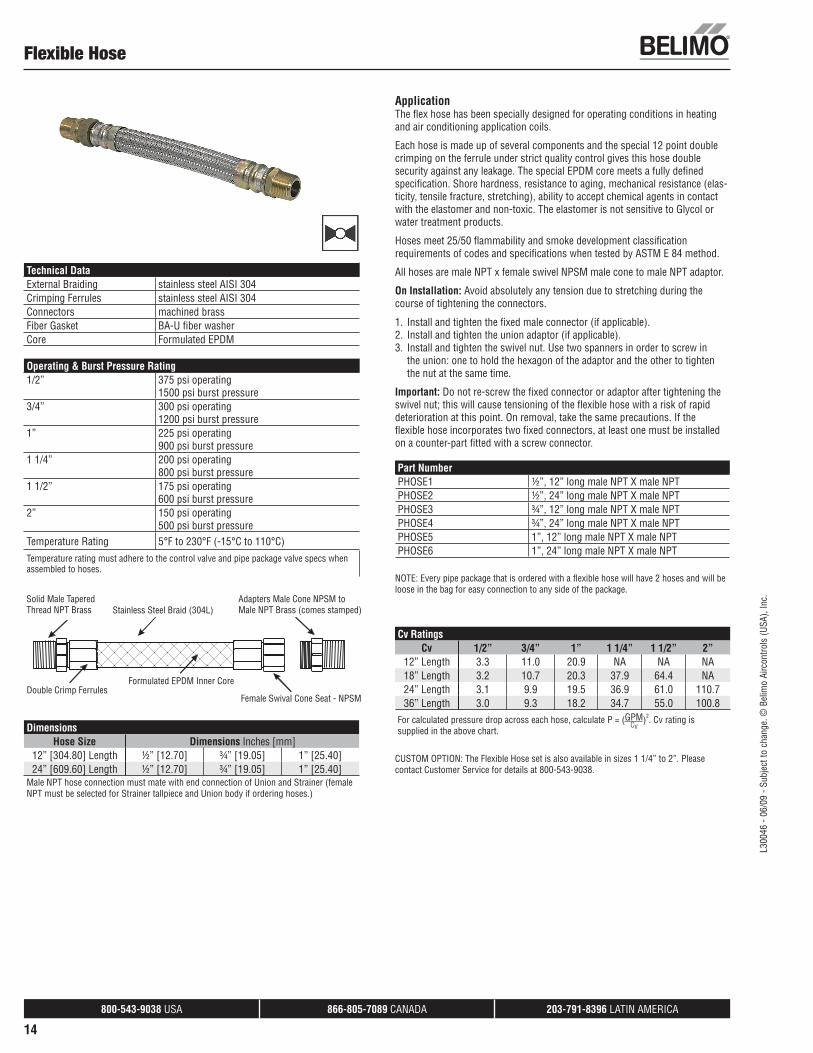
Flexible Hose
Technical DataExternal Braiding stainless steel AISI 304Crimping Ferrules stainless steel AISI 304Connectors machined brassFiber Gasket BA-U fi ber washerCore Formulated EPDM
Operating & Burst Pressure Rating1/2” 375 psi operating
1500 psi burst pressure3/4” 300 psi operating
1200 psi burst pressure1” 225 psi operating
900 psi burst pressure1 1/4” 200 psi operating
800 psi burst pressure1 1/2” 175 psi operating
600 psi burst pressure2” 150 psi operating
500 psi burst pressureTemperature Rating 5°F to 230°F (-15°C to 110°C)Temperature rating must adhere to the control valve and pipe package valve specs when assembled to hoses.
DimensionsHose Size Dimensions Inches [mm]
12” [304.80] Length ½” [12.70] ¾” [19.05] 1” [25.40]24” [609.60] Length ½” [12.70] ¾” [19.05] 1” [25.40]
Male NPT hose connection must mate with end connection of Union and Strainer (female NPT must be selected for Strainer tallpiece and Union body if ordering hoses.)
ApplicationThe fl ex hose has been specially designed for operating conditions in heating and air conditioning application coils.
Each hose is made up of several components and the special 12 point double crimping on the ferrule under strict quality control gives this hose double security against any leakage. The special EPDM core meets a fully defi ned specifi cation. Shore hardness, resistance to aging, mechanical resistance (elas-ticity, tensile fracture, stretching), ability to accept chemical agents in contact with the elastomer and non-toxic. The elastomer is not sensitive to Glycol or water treatment products.
Hoses meet 25/50 fl ammability and smoke development classifi cation requirements of codes and specifi cations when tested by ASTM E 84 method.
All hoses are male NPT x female swivel NPSM male cone to male NPT adaptor.
On Installation: Avoid absolutely any tension due to stretching during the course of tightening the connectors.
1. Install and tighten the fixed male connector (if applicable).2. Install and tighten the union adaptor (if applicable).3. Install and tighten the swivel nut. Use two spanners in order to screw in
the union: one to hold the hexagon of the adaptor and the other to tighten the nut at the same time.
Important: Do not re-screw the fi xed connector or adaptor after tightening the swivel nut; this will cause tensioning of the fl exible hose with a risk of rapid deterioration at this point. On removal, take the same precautions. If the fl exible hose incorporates two fi xed connectors, at least one must be installed on a counter-part fi tted with a screw connector.
Part NumberPHOSE1 ½”, 12” long male NPT X male NPTPHOSE2 ½”, 24” long male NPT X male NPTPHOSE3 ¾”, 12” long male NPT X male NPTPHOSE4 ¾”, 24” long male NPT X male NPTPHOSE5 1”, 12” long male NPT X male NPTPHOSE6 1”, 24” long male NPT X male NPT
NOTE: Every pipe package that is ordered with a fl exible hose will have 2 hoses and will be loose in the bag for easy connection to any side of the package.
Cv RatingsCv 1/2” 3/4” 1” 1 1/4” 1 1/2” 2”
12” Length 3.3 11.0 20.9 NA NA NA18” Length 3.2 10.7 20.3 37.9 64.4 NA24” Length 3.1 9.9 19.5 36.9 61.0 110.736” Length 3.0 9.3 18.2 34.7 55.0 100.8
For calculated pressure drop across each hose, calculate P = (GPM)2. Cv rating is supplied in the above chart.
Cv
CUSTOM OPTION: The Flexible Hose set is also available in sizes 1 1/4” to 2”. Please contact Customer Service for details at 800-543-9038.
L300
46 -
06/0
9 - S
ubje
ct to
cha
nge.
© B
elim
o Ai
rcon
trols
(USA
), In
c.
800-543-9038 USA 866-805-7089 CANADA 203-791-8396 LATIN AMERICA
15
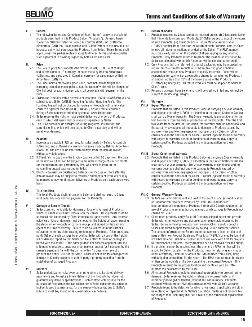
I. General1.1. The following Terms and Conditions of Sale (“Terms”) apply to the sale of
products described in this Product Guide (“Products”). As used herein, “Seller” or “Belimo” refers to Belimo Aircontrols (USA) Inc. or Belimo Aircontrols (CAN) Inc., as applicable, and “Client” refers to the individual or business entity that purchases the Products from Seller. These Terms shall apply unless the parties mutually agree to different terms and memorialize such agreement in a writing signed by both Client and Seller.
II. Price2.1. The Seller’s price for Products (the “Price”) is net, F.O.B. Point of Origin,
and is calculated in US currency for sales made by Belimo Aircontrols (USA), Inc. and calculated in Canadian currency for sales made by Belimo Aircontrols (CAN) Inc.
2.1. The Price, unless otherwise agreed upon, does not include freight and packaging (wooden crates, pallets, etc), the costs of which will be charged to Client at cost for each shipment and shall be payable with payment of the Price.
2.3. Orders for Products with a net value of less than US$300 (CAN$450) will be subject to a US$20 (CAN$35) handling fee (the “Handling Fee”). The Handling Fee will not be charged for orders of Products with a net value equal to or greater than US$300 (CAN$450) or for Products ordered through Seller’s internet ordering system at: www.belimo.com.
2.4. Seller reserves the right to make partial deliveries of orders of Products, each of which deliveries may be invoiced separately by Seller.
2.5. The Price does include charges for wiring diagrams, installation, and commissioning, which will be charged to Client separately and will be payable on demand.
III. Payment3.1. Invoices are payable in US currency for sales made by Belimo Aircontrols
(USA), Inc. and in Canadian currency for sales made by Belimo Aircontrols (CAN) Inc. and are due no later than 30 days from the date of invoice, without any deductions.
3.2. If Client fails to pay the entire invoice balance within 60 days from the date of the invoice, Client will be subject to an interest charge of 2% per month (or the maximum rate permitted by law, whichever is less) on the outstanding unpaid balance due to Seller.
3.3. Clients who maintain outstanding balances for 45 days or more after the date of invoice may be subject to restricted shipments of Products or may be required to pay for all future deliveries of Products on a cash-on-delivery basis.
IV. Title and Risk4.1. Title to all Products shall remain with Seller and shall not pass to Client
until Seller has received full payment for the Products.
V. Damage or Loss in Transit5.1. Seller assumes no liability for damage or loss of shipment of Products,
which risk shall at all times remain with the carrier. All shipments must be unpacked and examined by Client immediately upon receipt. Any external evidence of loss or damage must be noted on the freight bill accompanying the shipment of Products or carrier’s receipt and signed by the carrier’s agent at the time of delivery. Failure to do so will result in the carrier’s refusal to honor any claim relating to damage of Products. Client must also notify Seller of such damage by providing Seller with a copy of the freight bill or damage report so that Seller can file a claim for loss or damage in transit with the carrier. If the damage does not become apparent until the shipment is unpacked, customer must make a request for inspection by the carrier’s agent and file with the carrier within 15 days after receipt of product and notify Seller of the same. Seller is not liable for consequential damage to Client’s property or a third-party’s property resulting from the installation of damaged Products.
VI. Delivery6.1. Seller undertakes to make every attempt to adhere to its stated delivery
parameters and to make a timely delivery of the Products but does not guarantee any delivery specifications. Each contract entered into for the purchase of Products is not cancelable nor is Seller liable for any direct or indirect losses that may arise, for any reason whatsoever, due to Seller’s failure to meet any stated or assumed delivery schedules.
VII. Return of Goods7.1. Products received by Client cannot be returned unless: (i) Client alerts Seller
that it intends to return such Products, (ii) Seller agrees to accept the return of such Products, (iii) Client obtains a Return Material Authorization (“RMA”) number from Seller for the return of such Products, and (iv) Client follows all return instructions provided by the Seller. The RMA number must be clearly written on the outside of all packaging for any returned Products. Only Products returned to proper the location as instructed by Seller and identified with an RMA number will be considered for credit.
7.2. Only Products that are returned in original packaging may be accepted for return. Such returned Products must be received in good condition, adequate for resale as new Products to qualify for credit. Client will be responsible for payment of a restocking charge for all returned Products in an amount no less than 75% of the invoice value of the Products (“Restocking Charges”). All return Products must be shipped to Seller at Client’s cost.
7.3. Returns that result from Seller errors will be credited in full and will not be subject to Restocking Charges.
VIII. WarrantyVIII.A 5-year Warranty
8.1. Products that are listed in this Product Guide as carrying a 5-year warranty and shipped after May 1, 2000 to a location in the United States or Canada shall carry a 5-year warranty. The 5-year warranty is unconditional for the first two years from the date of production of the Products. After the first two years from the date of Production, the warranty shall be conditional and the warranty coverage shall not apply to damage to Products caused by ordinary wear and tear, negligence or improper use by Client, or other causes beyond the control of the Seller. Product -specific terms of warranty with regard to warranty period or conditions of warranty may apply to certain specified Products as stated in the documentation for those Products.
VIII.B 2-year Conditional Warranty8.2. Products that are listed in this Product Guide as carrying a 2-year warranty
and shipped after May 1, 2005 to a location in the United States or Canada shall carry a 2-year warranty. The 2-year warranty is conditional and the warranty coverage shall not apply to damage to Products caused by ordinary wear and tear, negligence or improper use by Client, or other causes beyond the control of the Seller. Product -specific terms of warranty with regard to warranty period or conditions of warranty may apply to certain specified Products as stated in the documentation for those Products.
VIII.C General Warranty Terms8.3. Seller’s warranty may be null and void in the event of any: (a) modification
or unauthorized repairs of Products by Client, (b) unauthorized incorporation or integration of Products into or with Client’s equipment, (c) use of Products in an unauthorized manner, or (d) damage to Products not caused by Seller.
8.4. Client must promptly notify Seller of Products’ alleged defect and provide Seller with other evidence and documentation reasonably requested by Seller. Before removing Products from service, Client should contact a Seller-authorized support technician by calling Belimo customer service. The contact information for Belimo customer service is listed on the back page of Belimo’s Product Guide and Price List (“PGPL”) or may be found at www.belimo.com. Belimo customer service will work with field technicians to troubleshoot problems. Many problems can be resolved over the phone.
8.5. If a problem cannot be resolved over the phone, an RMA number will be issued by Seller for return of the Products. Prior to returning any Products under a warranty, Client must obtain an RMA number from Seller, along with shipping instructions for the return. The RMA number must be clearly written on the outside of the box containing the returned Products. Only Products returned to the proper location and identified with an RMA number will be accepted by the Seller.
8.6. All returned Products should be packaged appropriately to prevent further damage. Seller reserves the right to refuse any returned material if improperly packaged or labeled (without an RMA number). Products returned without proper RMA documentation will void Seller’s warranty.
8.7. Products found to be defective for which a warranty is applicable will either be replaced or repaired at the Seller’s discretion. Seller is not responsible for charges that Client may incur as a result of the removal or replacement of Products.
Terms and Conditions of Sale of WarrantyL3
0046
- 06
/09
- Sub
ject
to c
hang
e. ©
Bel
imo
Airc
ontro
ls (U
SA),
Inc.
800-543-9038 USA 866-805-7089 CANADA 203-791-8396 LATIN AMERICA
16
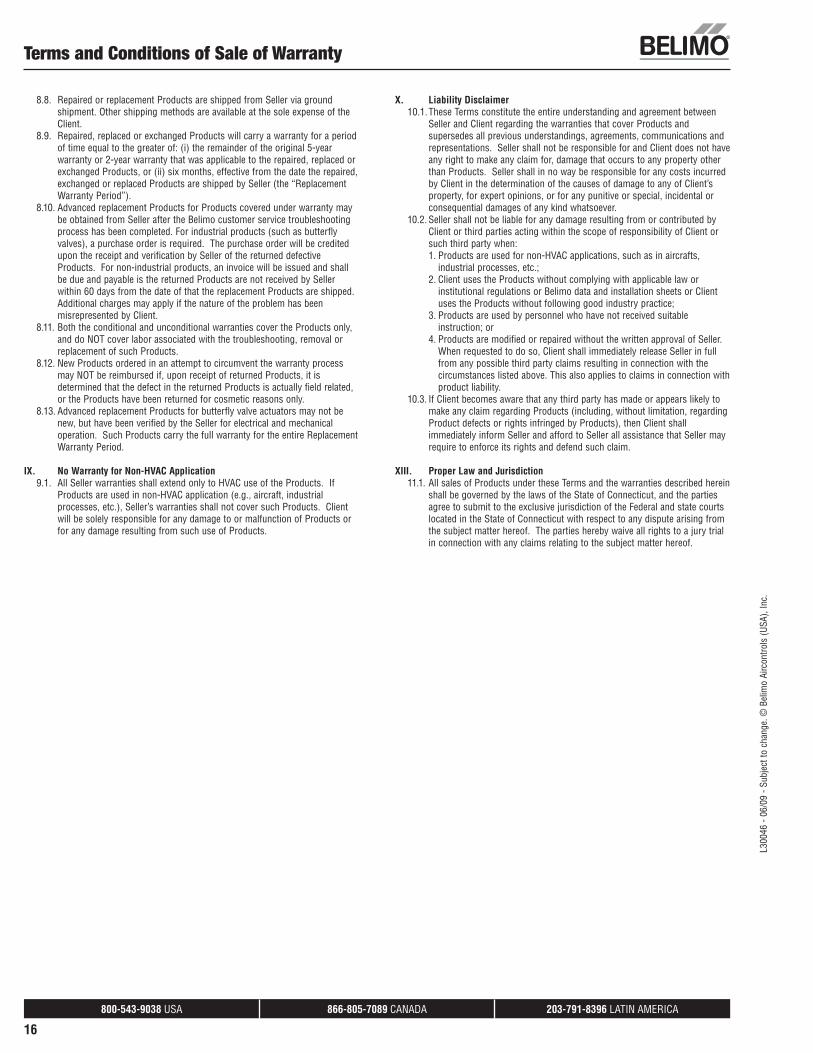
8.8. Repaired or replacement Products are shipped from Seller via ground shipment. Other shipping methods are available at the sole expense of the Client.
8.9. Repaired, replaced or exchanged Products will carry a warranty for a period of time equal to the greater of: (i) the remainder of the original 5-year warranty or 2-year warranty that was applicable to the repaired, replaced or exchanged Products, or (ii) six months, effective from the date the repaired, exchanged or replaced Products are shipped by Seller (the “Replacement Warranty Period”).
8.10. Advanced replacement Products for Products covered under warranty may be obtained from Seller after the Belimo customer service troubleshooting process has been completed. For industrial products (such as butterfly valves), a purchase order is required. The purchase order will be credited upon the receipt and verification by Seller of the returned defective Products. For non-industrial products, an invoice will be issued and shall be due and payable is the returned Products are not received by Seller within 60 days from the date of that the replacement Products are shipped. Additional charges may apply if the nature of the problem has been misrepresented by Client.
8.11. Both the conditional and unconditional warranties cover the Products only, and do NOT cover labor associated with the troubleshooting, removal or replacement of such Products.
8.12. New Products ordered in an attempt to circumvent the warranty process may NOT be reimbursed if, upon receipt of returned Products, it is determined that the defect in the returned Products is actually field related, or the Products have been returned for cosmetic reasons only.
8.13. Advanced replacement Products for butterfly valve actuators may not be new, but have been verified by the Seller for electrical and mechanical operation. Such Products carry the full warranty for the entire Replacement Warranty Period.
IX. No Warranty for Non-HVAC Application9.1. All Seller warranties shall extend only to HVAC use of the Products. If
Products are used in non-HVAC application (e.g., aircraft, industrial processes, etc.), Seller’s warranties shall not cover such Products. Client will be solely responsible for any damage to or malfunction of Products or for any damage resulting from such use of Products.
X. Liability Disclaimer10.1. These Terms constitute the entire understanding and agreement between
Seller and Client regarding the warranties that cover Products and supersedes all previous understandings, agreements, communications and representations. Seller shall not be responsible for and Client does not have any right to make any claim for, damage that occurs to any property other than Products. Seller shall in no way be responsible for any costs incurred by Client in the determination of the causes of damage to any of Client’s property, for expert opinions, or for any punitive or special, incidental or consequential damages of any kind whatsoever.
10.2. Seller shall not be liable for any damage resulting from or contributed by Client or third parties acting within the scope of responsibility of Client or such third party when:1. Products are used for non-HVAC applications, such as in aircrafts,
industrial processes, etc.;2. Client uses the Products without complying with applicable law or
institutional regulations or Belimo data and installation sheets or Client uses the Products without following good industry practice;
3. Products are used by personnel who have not received suitable instruction; or
4. Products are modified or repaired without the written approval of Seller. When requested to do so, Client shall immediately release Seller in full
from any possible third party claims resulting in connection with the circumstances listed above. This also applies to claims in connection with product liability.
10.3. If Client becomes aware that any third party has made or appears likely to make any claim regarding Products (including, without limitation, regarding Product defects or rights infringed by Products), then Client shall immediately inform Seller and afford to Seller all assistance that Seller may require to enforce its rights and defend such claim.
XIII. Proper Law and Jurisdiction11.1. All sales of Products under these Terms and the warranties described herein
shall be governed by the laws of the State of Connecticut, and the parties agree to submit to the exclusive jurisdiction of the Federal and state courts located in the State of Connecticut with respect to any dispute arising from the subject matter hereof. The parties hereby waive all rights to a jury trial in connection with any claims relating to the subject matter hereof.
Terms and Conditions of Sale of Warranty
L300
46 -
06/0
9 - S
ubje
ct to
cha
nge.
© B
elim
o Ai
rcon
trols
(USA
), In
c.
800-543-9038 USA 866-805-7089 CANADA 203-791-8396 LATIN AMERICA
K209
40 -
10/
08 -
Sub
ject
to c
hang
e. ©
Bel
imo
Airc
ontr
ols
(USA
), In
c.
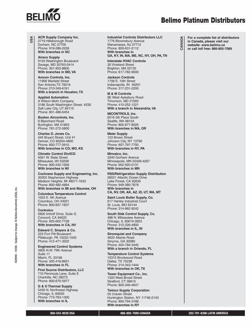
ACR Supply Company Inc.2719 Hillsborough RoadDurham, NC 27705Phone: 919-286-2228With branches in NC
Aireco Supply9120 Washington BoulevardSavage, MD 20763-0414Phone: 301-953-8800With branches in MD, VA
Amcon Controls, Inc.11906 Warfield StreetSan Antonio,TX 78216Phone: 210-349-6161With a branch in Houston, TX
Applied AutomationA Wilson Mohr Company3186 South Washington Street, #230Salt Lake City, UT 84115Phone: 801-486-6454
Boston Aircontrols, Inc.8 Blanchard RoadBurlington, MA 01803Phone: 781-272-5800
Charles D. Jones Co.445 Bryant Street, Unit #1Denver, CO 80204-4800Phone: 800-777-0910With branches in CO, MO, KS
Climatic Control Div/ICD5061 W. State StreetMilwaukee, WI 53208Phone: 800-242-1656With branches in WI
Cochrane Supply and Engineering, Inc.30303 Stephenson HighwayMadison Heights, MI 48071-1633Phone: 800-482-4894With branches in MI and Maumee, OH
Columbus Temperature Control1053 E. 5th AvenueColumbus, OH 43201Phone: 800-837-1837
Controlco5600 Imhoff Drive, Suite GConcord, CA 94520Phone: 925-602-7728With branches in CA, NV
Edward C. Smyers & Co.223 Fort Pitt BoulevardPittsburgh, PA 15222-1505Phone: 412-471-3222
Engineered Control Systems4805 N.W. 79th AvenueSuite 11Miami, FL 33166Phone: 305-418-8901With branches in FL
First Source Distributors, LLC710 Peninsula Lane, Suite ECharlotte, NC 28273Phone: 800-670-5977
G & O Thermal Supply5435 N. Northwest HighwayChicago, IL 60630Phone: 773-763-1300With branches in IL
Industrial Controls Distributors LLC1776 Bloomsbury AvenueWanamassa, NJ 07712Phone: 800-631-2112With branches inGA, KY, IN, MA, ME, NC, NY, OH, PA, TN
Interstate HVAC Controls30 Vineland StreetBrighton, MA 02135 Phone: 617-782-9000
Jackson Controls1708 E. 10th StreetIndianapolis, IN 46201Phone: 317-231-2200
M & M Controls9E West Aylesbury RoadTimonium, MD 21093Phone: 410-252-1221With a branch in Alexandria, VA
MICONTROLS, Inc.6516 5th Place SouthSeattle, WA 98124Phone: 800-877-8026With branches in WA, OR
Meier Supply123 Brown StreetJohnson City, NY 13790 Phone: 607-797-7700With branches in NY, PA
Minvalco, Inc.3340 Gorham AvenueMinneapolis, MN 55426-4267Phone: 952-920-0131With branches in MN
RSD/Refrigeration Supply Distribution 26021 Atlantic Ocean DriveLake Forest, CA 92630Phone: 949-380-7878With branches inCA, NV, OR, AK, AZ, ID, UT, WA, MT
Saint Louis Boiler Supply, Co. 617 Hanley Industrial CourtSt. Louis, MO 63144Phone: 314-962-9242
South Side Control Supply, Co. 488 N. Milwaukee AvenueChicago, IL 60610-3923Phone: 312-226-4900With branches in IL, IN
Stromquist and Company4620 Atlanta RoadSmyrna, GA 30080Phone: 404-794-3440With a branch in Orlando, FL
Temperature Control Systems10315 Brockwood RoadDallas, TX 75238Phone: 214-343-1444With branches in OK, TX
Tower Equipment Co., Inc.1320 West Broad StreetStratford, CT 06615Phone: 800-346-4647
Twinco Supply Corporation55 Craven StreetHuntington Station, NY 11746-2143Phone: 800-794-3188With branches in NY
Belimo Platinum DistributorsU
SA
CA
NA
DA For a complete list of distributors
in Canada, please visit our website: www.belimo.caor call toll free: 866-805-7089

K209
40 -
10/
08 -
Sub
ject
to c
hang
e. ©
Bel
imo
Airc
ontr
ols
(USA
), In
c.
BELIMO AmericasUSA Locations, 43 Old Ridgebury Road, Danbury, CT 06810Tel. 800-543-9038, Fax 800-228-8283, [email protected]
1675 East Prater Way, Suite 101, Sparks, NV 89434Tel. 800 987-9042, Fax 800-987-8875, [email protected]
Canada Locations, 14/16 – 5716 Coopers Avenue, Mississauga, Ontario L4Z 2E8Tel. 866-805-7089, Fax 905-712-3124, [email protected]
Latin America Customer Service, Tel. 203-791-8396, Fax 203-791-9139, [email protected]
Belimo worldwide: www.belimo.com