Embed Size (px)
Citation preview

FEBRUARY 2007
TECHNICAL DIGEST 12EVALUATION ANDMODIFICATION OFOPEN-WEB STEELJOISTS AND JOISTGIRDERS
The information presented in this publication has been developed by James M. Fisher, PhD, PE, Consulting Engineer for the Steel Joist Institute in conjunction with the SJI’s Engineering Practice Committee and Perry S. Green, PhD, Technical Director and is produced in accordance with recognized engineering principles and is for general information only. The SJI and its committees have made a concerted effort to present accurate, reliable, and useful information on the evaluation, modification and strengthening of steel joists and Joist Girders. The information contained in this digest should not be used or relied upon for any specific project without competent professional assessment of its accuracy, suitability and applicability by a licensed professional engineer or architect. The publication of the material contained in this Technical Digest is not intended as a representation or warranty on the part of the Steel Joist Institute. Any person making use of this information does so at one’s own risk and assumes all liability arising from such use. Federal Regulations Governing Erection of Joist Products Steel joists and Joist Girders must be erected in accordance with the Occupational Safety and Health Administration (OSHA), U.S. Department of Labor 29 CFR Part 1926 Safety Standards for Steel Erection. The erection of Open Web Steel Joists is governed by Section 1926.757 of this Federal Regulation.
Copyright © 2007
by
Steel Joist Institute 3127 Mr. Joe White Ave. Myrtle Beach, SC 29577
www.steeljoist.org All rights reserved. This Technical Digest or any part thereof must not be reproduced in any form without the written permission of the Steel Joist Institute.
Printed in the United States of America
First Edition First Printing – February 2007

i
ACKNOWLEDGEMENT
The author would like to thank SJI’s Technical Director, Perry S. Green, Ph.D., and the members of the Engineering Practice Committee of the Steel Joist Institute for their review and contributions to the writing of this digest.
FOREWORD
This Technical Digest is another addition to the series of Steel Joist Institute publications designed to give the reader information regarding the application and usage of steel joists and Joist Girders. Technical Digest No. 12 concerns itself with the evaluation of existing steel joists and Joist Girders to carry additional loads not accounted for in their original design. The technical digest also addresses situations where the configuration and/or the original geometry of the steel joists or Joist Girders need to be modified in the field. This and other SJI Technical Digests serve to highlight specific areas of design and/or application for the benefit of architects, building inspectors, building officials, designers, engineers, erectors, students and others.
ii
TABLE OF CONTENTS
ACKNOWLEDGEMENT ……………………………………………………… i
FOREWORD …………………………………………………………………... i
TABLE OF CONTENTS ………………………………………………………. ii
BACKGROUND ……………………………………………………………….. iii
GLOSSARY ……………………………………………………………………. iv
Chapter 1 EVALUATION OF EXISTING JOIST STRENGTH ……….. 1
Chapter 2 METHODS OF SUPPORTING ADDITIONAL LOAD …..... 7
Chapter 3 DESIGN APPROACHES FOR STRENGTHENING JOISTS ………………………………………………………… 19
Chapter 4 DESIGN APPROACHES FOR MODIFYING JOISTS - SHORTENING AND LENGTHENING ……………………... 80
Chapter 5 OTHER CONSIDERATIONS ……………………………….. 87
Chapter 6 SUMMARY ……………………………………………………. 91
REFERENCES ………………………………………………………………… 92
Appendix A Joist Investigation Form ……………………………….......... 93
Appendix B Common Properties of Equal Leg Angles with Leg Sizes 2 in. or Less 94
iii
BACKGROUND
Evaluation and modification of joists is often required due to the addition of roof top units, underhung conveyors, loading increases, field deviations, or other changes not contemplated in the original specification for the joists or Joist Girders. The purpose of this digest is to present procedures, and to suggest details for the modification or strengthening of open web steel joists and Joist Girders. Both open web steel joists and Joist Girders will be referred to as joists in this digest.
iv
GLOSSARY
NOTES: Terms in Bold and their definitions come from the AISC AND AISI STANDARD Standard Definitions for Use in the Design of Steel Structures, 2004 Edition, First Printing April 2005. * These terms are usually qualified by the type of load effect, e.g., nominal tensile
strength, available compressive strength, design flexural strength. ASD (Allowable Strength Design). Method of proportioning structural components such that the allowable strength equals or exceeds the required strength of the component under the action of the ASD load combinations. Allowable Strength*. Nominal strength divided by the safety factor, Rn/Ω. Available Strength*. Design strength or allowable strength as appropriate. Bearing. The distance that the bearing shoe or seat of a joist or Joist Girder extends over its masonry, concrete or steel support. Bridging. In general, a member connected to a joist to brace it from lateral movement. Buckling. Limit state of sudden change in the geometry of a structure or any of its elements under a critical loading condition. Buckling Strength. Nominal strength for buckling or instability limit states. Camber. An upward curvature of the chords of a joist or Joist Girder induced during shop fabrication. Note, this is in addition to the pitch of the top chord. Chords. The top and bottom members of a joist or Joist Girder. When a chord is comprised of two angles there is usually a gap between the members. Cold-Formed Steel Structural Member. Shape manufactured by press-braking blanks sheared from sheets, cut lengths of coils or plates, or by roll forming cold- or hot-rolled coils or sheets; both forming operations being performed at ambient room temperature, that is, without manifest addition of heat such as would be required for hot forming.

v
Composite Section. Combined existing member and reinforcing member. Connection. Combination of structural elements and joints used to transmit forces between two or more members. See also splice. Deck. A floor or roof covering made out of gage metal attached by welding or mechanical means to joists, beams, purlins, or other structural members and can be galvanized, painted, or unpainted. Design Load. Applied load determined in accordance with either LRFD load combinations or ASD load combinations, whichever is applicable. Design Strength*. Resistance factor multiplied by the nominal strength, φRn. End Diagonal or Web. The first web member on either end of a joist or Joist Girder which begins at the top chord at the seat and ends at the first bottom chord panel point. End Welds. Welds at the ends of an existing member or the reinforcing member. Existing Member. The member originally supplied in the joist or Joist Girder. Filler. A rod, plate or angle welded between a two angle web member or between a top or bottom chord panel to tie them together, usually located at the middle of the member. Joint. Area where two or more ends, surfaces or edges are attached. Categorized by type of fastener or weld used and the method of force transfer. Joist. A structural load-carrying member with an open web system which supports floors and roofs utilizing hot-rolled or cold-formed steel and is designed as a simple span member. Currently, the SJI has the following joist designations: K-Series including KCS, LH-Series and DLH-Series. Joist Girder. A primary structural load-carrying member with an open web system designed as a simple span supporting equally spaced concentrated loads of a floor or roof system acting at the panel points of the member and utilizing hot-rolled or cold-formed steel. Load. Force or other action that results from the weight of building materials, occupants and their possessions, environmental effects, differential movement, or restrained dimensional changes. LRFD (Load and Resistance Factor Design). Method of proportioning structural components such that the design strength equals or exceeds the required strength of the component under the action of the LRFD load combinations.

vi
Material. Joists, Joist Girders and accessories as provided by the seller. Nominal Strength*. Strength of a structure or component (without the resistance factor or safety factor applied) to resist the load effects, as determined in accordance with the Standard Specifications. Preload Force. Force in the existing member not removed by shoring. Reinforcing Member. The added member(s). Required Strength*. Forces, stresses, and deformations produced in a structural component, determined by either structural analysis, for the LRFD or ASD load combinations, as appropriate, or as specified by the Standard Specifications. Resistance Factor, φ. Factor that accounts for deviations of the actual strength from the nominal strength, deviations of the actual load from the nominal load, uncertainties in the analysis that transforms the load into a load effect and for the manner and consequences of failure. Safety Factor, Ω. Factor that accounts for deviations of the actual strength from the nominal strength, deviations of the actual load from the nominal load, uncertainties in the analysis that transforms the load into a load effect and for the manner and consequences of failure. Slenderness Ratio. The ratio of the effective length of a column to the radius of gyration of the column about the same axis of bending. Span. The centerline-to-centerline distance between structural steel supports such as a beam, column or Joist Girder or the clear span distance plus four inches onto a masonry or concrete wall. Specified Minimum Yield Stress. Lower limit of yield stress specified for a material as defined by ASTM. Specifying Professional. The licensed professional who is responsible for sealing the building Contract Documents, which indicates that he or she has performed or supervised the analysis, design and document preparation for the structure and has knowledge of the load-carrying structural system. Splice. Connection between two structural members joined at their ends by either bolting or welding to form a single, longer member. Stability. Condition reached in the loading of a structural component, frame or structure in which a slight disturbance in the loads or geometry does not produce large displacements.
vii
Standard Specifications. Documents developed and maintained by the Steel Joist Institute for the design and manufacture of open web steel joists and Joist Girders. The term “SJI Standard Specifications” encompass by reference the following: ANSI/SJI-K1.1 Standard Specification for Open Web Steel Joists, K-Series; ANSI/SJI-LH/DLH-1.1 Standard Specifications for Longspan Steel Joists, LH-Series and Deep Longspan Steel Joists, DLH-Series; and ANSI/SJI-JG-1.1 Standard Specifications for Joist Girders. Structural Analysis. Determination of load effects on members and connections based on principles of structural mechanics. Tagged End. The end of a joist or Joist Girder where an identification or piece mark is shown by a metal tag. The member must be erected with this tagged end in the same position as the tagged end noted on the placement plan. Webs. The vertical or diagonal members joined at the top and bottom chords of a joist or Joist Girder to form triangular patterns. Yield Point. First stress in a material at which an increase in strain occurs without an increase in stress as defined by ASTM. Yield Strength. Stress at which a material exhibits a specified limiting deviation from the proportionality of stress to strain as defined by ASTM. Yield Stress. Generic term to denote either yield point or yield strength, as appropriate for the material.
1
CHAPTER 1
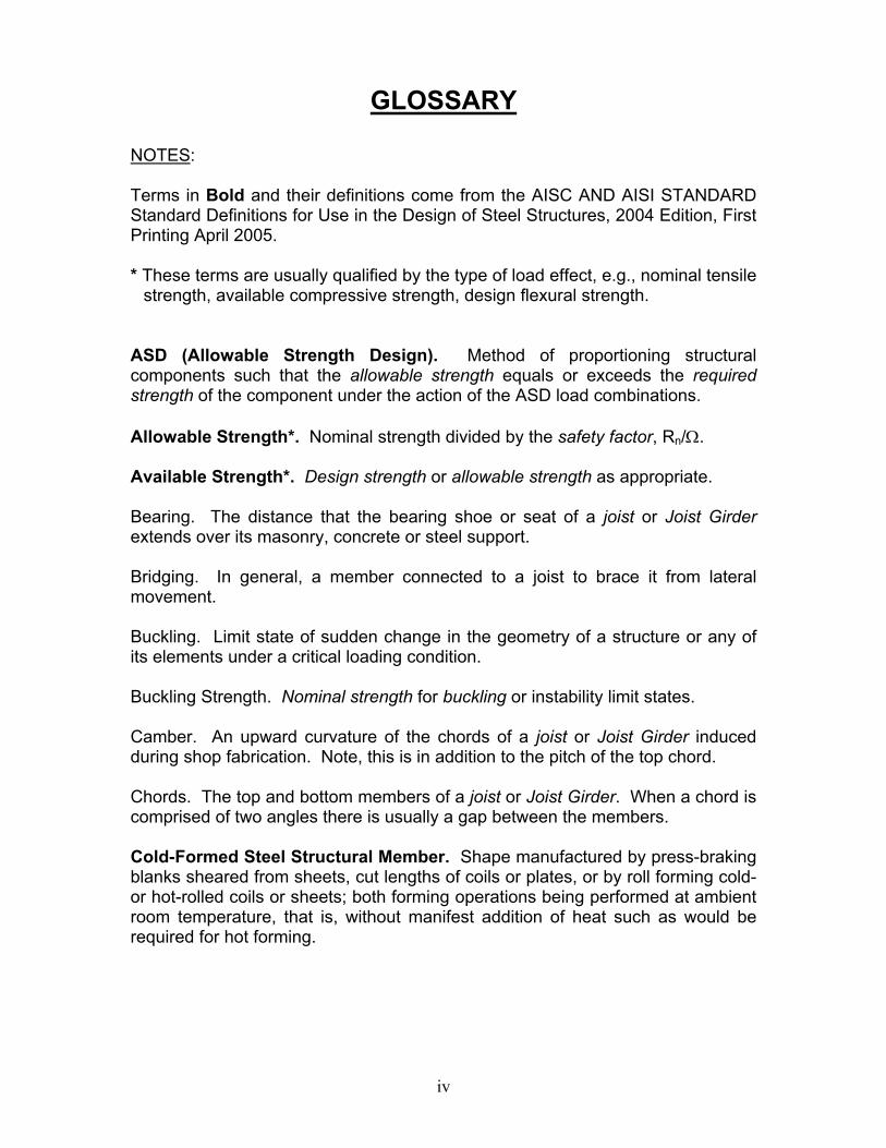
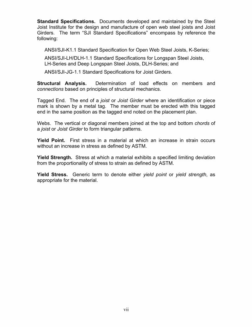
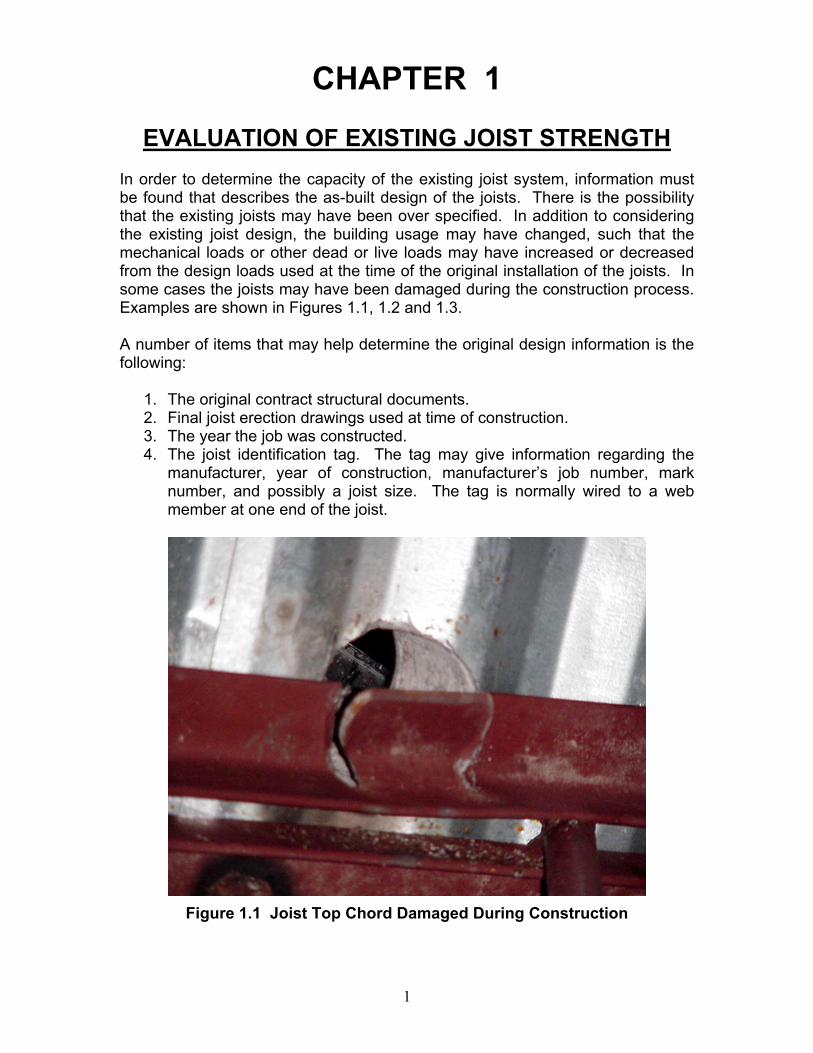
EVALUATION OF EXISTING JOIST STRENGTH In order to determine the capacity of the existing joist system, information must be found that describes the as-built design of the joists. There is the possibility that the existing joists may have been over specified. In addition to considering the existing joist design, the building usage may have changed, such that the mechanical loads or other dead or live loads may have increased or decreased from the design loads used at the time of the original installation of the joists. In some cases the joists may have been damaged during the construction process. Examples are shown in Figures 1.1, 1.2 and 1.3. A number of items that may help determine the original design information is the following:
1. The original contract structural documents. 2. Final joist erection drawings used at time of construction. 3. The year the job was constructed. 4. The joist identification tag. The tag may give information regarding the
manufacturer, year of construction, manufacturer’s job number, mark number, and possibly a joist size. The tag is normally wired to a web member at one end of the joist.
Figure 1.1 Joist Top Chord Damaged During Construction
2
Figure 1.2 Joist Top Chord Damaged During Construction
Figure 1.3 Joist Bottom Chord Damaged During Construction
If the joist designation can be found, the capacity can be determined using the Steel Joist Institute (SJI) Load Tables, which are contained in the SJI 75-Year Joist Manual (SJI 2003). The SJI Specifications for all joists manufactured from 1928 to 2003 are contained in the digest. From the joist designation, find the designation and appropriate year in the Manual; and then obtain the uniform load capacity from the appropriate load table. From the uniform load capacity determine the moment capacity, and shear strength of the webs.
3
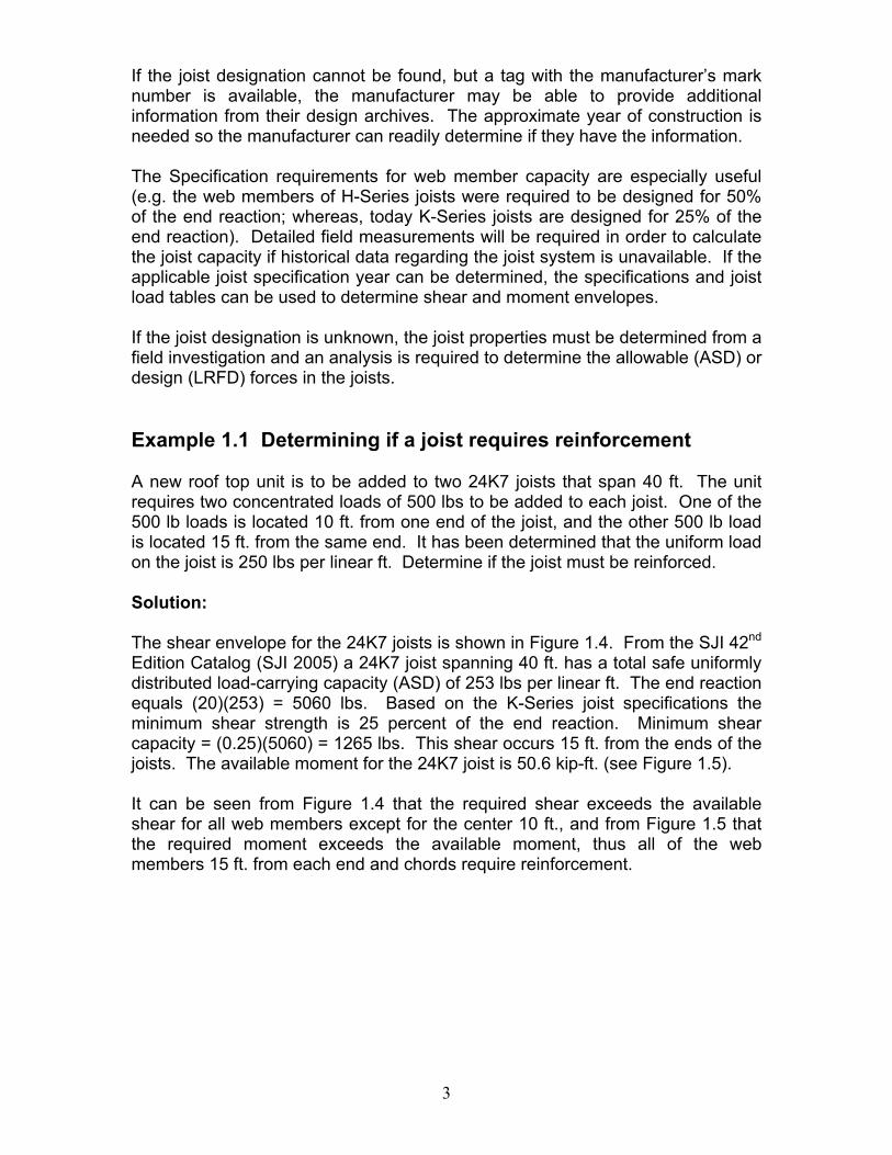
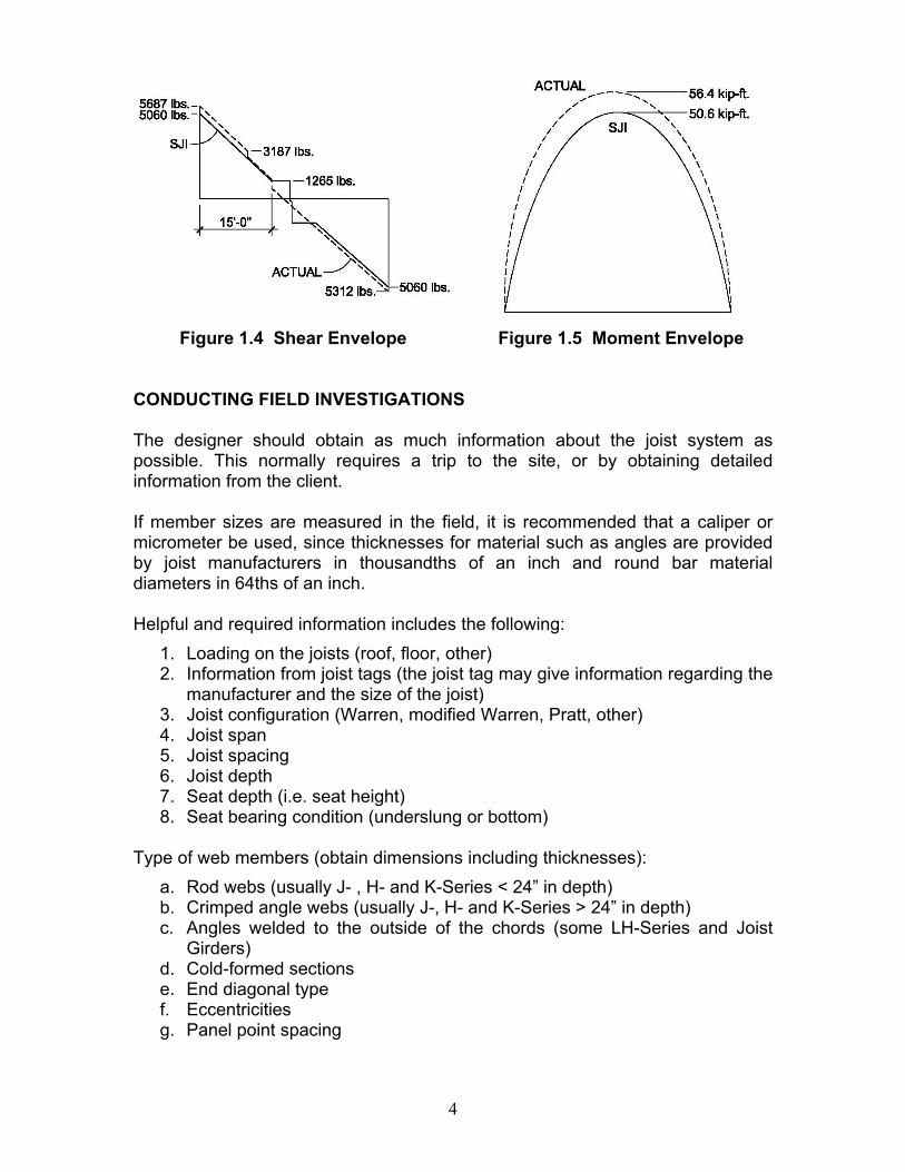
If the joist designation cannot be found, but a tag with the manufacturer’s mark number is available, the manufacturer may be able to provide additional information from their design archives. The approximate year of construction is needed so the manufacturer can readily determine if they have the information. The Specification requirements for web member capacity are especially useful (e.g. the web members of H-Series joists were required to be designed for 50% of the end reaction; whereas, today K-Series joists are designed for 25% of the end reaction). Detailed field measurements will be required in order to calculate the joist capacity if historical data regarding the joist system is unavailable. If the applicable joist specification year can be determined, the specifications and joist load tables can be used to determine shear and moment envelopes. If the joist designation is unknown, the joist properties must be determined from a field investigation and an analysis is required to determine the allowable (ASD) or design (LRFD) forces in the joists. Example 1.1 Determining if a joist requires reinforcement A new roof top unit is to be added to two 24K7 joists that span 40 ft. The unit requires two concentrated loads of 500 lbs to be added to each joist. One of the 500 lb loads is located 10 ft. from one end of the joist, and the other 500 lb load is located 15 ft. from the same end. It has been determined that the uniform load on the joist is 250 lbs per linear ft. Determine if the joist must be reinforced. Solution: The shear envelope for the 24K7 joists is shown in Figure 1.4. From the SJI 42nd Edition Catalog (SJI 2005) a 24K7 joist spanning 40 ft. has a total safe uniformly distributed load-carrying capacity (ASD) of 253 lbs per linear ft. The end reaction equals (20)(253) = 5060 lbs. Based on the K-Series joist specifications the minimum shear strength is 25 percent of the end reaction. Minimum shear capacity = (0.25)(5060) = 1265 lbs. This shear occurs 15 ft. from the ends of the joists. The available moment for the 24K7 joist is 50.6 kip-ft. (see Figure 1.5). It can be seen from Figure 1.4 that the required shear exceeds the available shear for all web members except for the center 10 ft., and from Figure 1.5 that the required moment exceeds the available moment, thus all of the web members 15 ft. from each end and chords require reinforcement.
4
Figure 1.4 Shear Envelope Figure 1.5 Moment Envelope
CONDUCTING FIELD INVESTIGATIONS The designer should obtain as much information about the joist system as possible. This normally requires a trip to the site, or by obtaining detailed information from the client. If member sizes are measured in the field, it is recommended that a caliper or micrometer be used, since thicknesses for material such as angles are provided by joist manufacturers in thousandths of an inch and round bar material diameters in 64ths of an inch. Helpful and required information includes the following:
1. Loading on the joists (roof, floor, other) 2. Information from joist tags (the joist tag may give information regarding the
manufacturer and the size of the joist) 3. Joist configuration (Warren, modified Warren, Pratt, other) 4. Joist span 5. Joist spacing 6. Joist depth 7. Seat depth (i.e. seat height) 8. Seat bearing condition (underslung or bottom)
Type of web members (obtain dimensions including thicknesses): a. Rod webs (usually J- , H- and K-Series < 24” in depth) b. Crimped angle webs (usually J-, H- and K-Series > 24” in depth) c. Angles welded to the outside of the chords (some LH-Series and Joist
Girders) d. Cold-formed sections e. End diagonal type f. Eccentricities g. Panel point spacing

5
Type of chords (obtain dimensions including thicknesses, separation distance along with identifying which members or panels contain fillers or ties):
a. Double angles b. Cold-formed sections c. Rods d. Splices
Weld information (Depending on joint configurations, it may not be possible to determine exact weld sizes and lengths; however, general quality from a visual inspection should be possible.)
Type of bridging and locations. Quality of bridging connections. Anchorage of bridging. Interferences. Condition of joists and the existing deck. Tension coupon samples may be required from chords and web members to determine yield strength, if not known.
When the joist manufacturer can be determined from the field investigation, then the investigator should contact them (if they are still in business) for possible assistance in determining the load-carrying capacity of the joist. It is possible that the manufacturer might still have the original calculations for the project being evaluated if it was constructed within the last 10 years. The Steel Joist Institute can also be of assistance in determining the type of joist and it’s load-carrying capacity. A Joist Investigation Form, found in Appendix A, has been developed by the SJI to assist Engineers, Architects, Specifying Professionals, Contractors and others to help identify older joists. The form can be filled out on-line or downloaded from the SJI website, www.steeljoist.org and returned to the SJI office for their assistance. ANALYSIS CONSIDERATIONS There are several points that should be considered when analyzing joists to determine their capacity.
1. Pinned connections are generally assumed for the web member ends. 2. The Specification for standard K-Series joists permits bending moments to
be neglected in the top chord provided the panel point spacing does not exceed 24 inches and the applied loads are uniform.
3. A first order analysis is used. 4. For K-Series joists the SJI permits eccentricities at the chord joints to be
neglected in the analysis provided that the “3/4 rule” is followed. This rule comes from Section 4.5(d) of the SJI Standard Specifications for Open Web Steel Joists, K-Series (SJI 2005). The Specification states,
6
“Members connected at a joint shall have their centroidal axes meet at a point if practical. Otherwise, due consideration shall be given to the effect of eccentricity. In no case shall eccentricity of any web member at a joint exceed 3/4 of the over-all dimension, measured in the plane of the web, of the largest member connected. The eccentricity of any web member shall be the perpendicular distance from the centroidal axis of that web member to the point on the centroidal axis of the chord which is vertically above or below the intersection of the centroidal axes of the web members forming the joint.”
The SJI Specifications for LH- and DLH-Series joists and Joist Girders, Sections 103.4(d) and 1003.4(d), respectively prescribe that, “Eccentricity on either side of the centroid of chord members may be neglected when it does not exceed the distance between the centroid and the back of the chord.”
The author suggests that when analyzing joists with the reinforcing members in place that the following criteria are used in the model:
1. Include joint eccentricities when deemed necessary. 2. Use pinned connections at the web member ends as is the case for
standard joists.
7
CHAPTER 2
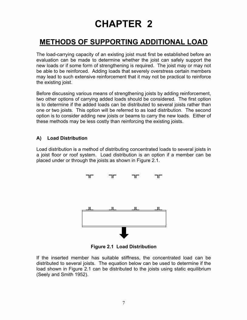
METHODS OF SUPPORTING ADDITIONAL LOAD The load-carrying capacity of an existing joist must first be established before an evaluation can be made to determine whether the joist can safely support the new loads or if some form of strengthening is required. The joist may or may not be able to be reinforced. Adding loads that severely overstress certain members may lead to such extensive reinforcement that it may not be practical to reinforce the existing joist. Before discussing various means of strengthening joists by adding reinforcement, two other options of carrying added loads should be considered. The first option is to determine if the added loads can be distributed to several joists rather than one or two joists. This option will be referred to as load distribution. The second option is to consider adding new joists or beams to carry the new loads. Either of these methods may be less costly than reinforcing the existing joists. A) Load Distribution Load distribution is a method of distributing concentrated loads to several joists in a joist floor or roof system. Load distribution is an option if a member can be placed under or through the joists as shown in Figure 2.1.
Figure 2.1 Load Distribution
If the inserted member has suitable stiffness, the concentrated load can be distributed to several joists. The equation below can be used to determine if the load shown in Figure 2.1 can be distributed to the joists using static equilibrium (Seely and Smith 1952).
8
The relative stiffness of the joists and the distribution beam is defined by the characteristic parameter beta as defined in Equation 2-1.
( )( )4
EI4SK
=β Eq. 2-1
where,
K = stiffness of the joist, kips/in. S = spacing of the joists, in. E = modulus of elasticity for the beam, ksi I = moment of inertia of the beam, in.4 β = characteristic parameter, 1/in.
If S is less than π/4β, the spacing limit is not exceeded, and if the length of the beam is less than 1/β, the beam may be considered to be rigid with respect to the supporting joists, and the reactions to the joists may be determined by static equilibrium. If the criteria are not satisfied, strength of material solutions for beams on elastic foundations can be used to determine the reactions to the joists, or a computer solution can be used where the distribution beam is modeled and the joists are modeled as springs to determine the load distribution. In lieu of the beam shown in Figure 2.1, it may be possible to design a beam or truss system that can pass through the openings in the joists to distribute the load. It should be noted that if the concentrated load is located near the end of the joists, the Load Distribution procedure would require an extremely stiff transfer beam, thus the procedure may not always be practical. Example 2.1 Load Distribution for an underhung monorail
(beam) This example illustrates how load distribution between three joists can be used to possibly eliminate the need for strengthening a joist system or to minimize the amount of reinforcing required by reducing the load applied to each joist. The example also illustrates how to design the distribution beam which is placed below the bottom chord of the joists. A new underhung monorail is to be hung from the bottom chord of several 30K12 joists which span 36 ft. The joists are spaced 2.5 ft. apart. The monorail adds a 1,200 pound concentrated load to a single joist. The concentrated load is located 10 ft. from the joist end.
9
Solution: 1. Determine the stiffness of the joists:
The approximate joist moment of inertia can be determined using Equation 2-2 that can be found in the introduction to the Standard [ASD or LRFD] Load Table for Open Web Steel Joists, K-Series (SJI 2005),
( )( )( )63LLj 10LW767.26I −= Eq. 2-2
where, WLL = live load deflection (red figure in the Load Table), plf L = (Span – 0.33), ft.
From the Load Table, the live load deflection for a 30K12 joist with a 36 ft. span is, WLL = 392 plf
( )( )( ) 463
j .in4761067.35392767.26I == − 2. Divide Ij by 1.15 to account for shear deflection.
∆=
==
PK
.in41415.1
476I 4eff,j
From the AISC Manual of Steel Construction (AISC 2005), Table 3-23 for the case of a simple beam – concentrated load at any point,
EIL3bPa 22
=∆
Thus,
22eff,j
eff,j
22 baLEI3
LEI3bPa
PPK ==∆
=
( )( )( )( )( )( )[ ] ( )( )[ ]
.ink0.1112101226
1267.35414290003K 22 ==
10
Determine the beam size necessary to distribute the load to the three joists:
Try W16X26 Ix = 301 in.4
( )( ) ( )( )( )
144 .in0101.0
301290004300.11
EI4SK −===β
Check if spacing, .in6.774
S =βπ
<
S = 30 in. < 77.6 in. Therefore, OK
Check the length of monorail beam < 1/β
L = 5.0 ft. = 60 in.
1/β = 1/0.0101 = 98.8 in.
60 in. < 98.8 in. Therefore, OK
The beam may be assumed to act as a rigid body in delivering load to the joists.
3. Solve for the reaction at each joist:
Since the beam can be considered rigid, each joist supports lbs4003
1200=
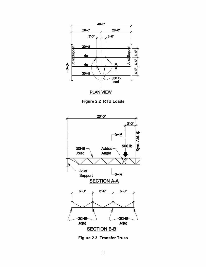
additional load. Example 2.2 Load distribution for roof top units (interior joist) This example illustrates how load distribution between several joists can be used to eliminate the need for strengthening a joist system or to minimize the amount of reinforcing required. The example also illustrates how to design a truss system within the depth of the joists so that head room below the joists is not reduced. A new roof top unit is to be located on top of existing 30H8 joists. The building was erected in 1975. The joists span 40 feet and are 6 ft. on center. A sketch indicating the location of the loads from the roof top unit is shown in Figure 2.2. The reactions from the unit and the curbing are also shown in the figure. Figure 2.3 shows the location and suggested geometry of the transfer truss.
11
Figure 2.2 RTU Loads
Figure 2.3 Transfer Truss

12
Solution: 1. Determine the stiffness of the joists:
( )( )( )63LLj 10LW767.26I −=
From the 1974 H-Series Load Table (SJI 2003), the live load deflection for a 30H8 joist with a 40 ft. span is,
WLL = 262 plf
( )( )( ) 463
j .in4381067.39262767.26I == − 2. Divide Ij by 1.15 to account for shear deflection.
4eff,j .in381
15.1438I ==
22eff,j
eff,j
22 baLEI3
LEI3bPa
PPK ==∆
=
( )( )( )( )( )( )[ ] ( )( )[ ]
.ink98.412231217
1267.39381290003K 22 ==
Determine the moment of inertia of the transfer truss necessary to distribute the load to the four joists:
Try a 3 x 3 x 1/4 in. angle for the top and bottom chords of the transfer truss.
In the calculation below, the top and bottom chords of the 30H8 joists are assumed to be 2 in. angles.
( )( )( ) 422
x .in426836.021544.12Ad2I =−−==
4eff .in370
15.1426I =≈
( )( ) ( )( )( )
144 .in0066.0
3702900046098.4
EI4SK −===β
13
Check if spacing, .in4.1184
S =βπ
<
S = 60 in. < 118.4 in. Therefore, OK
Check the length of truss < 1/β
L = 18 ft. = 216 in.
1/β = 1/0.0066 = 151 in.
216 in. > 151 in. Therefore, NG
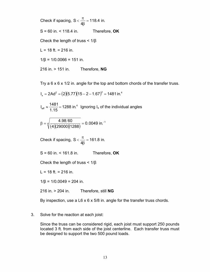
Try a 6 x 6 x 1/2 in. angle for the top and bottom chords of the transfer truss.
( )( )( ) 422x .in148167.121577.52Ad2I =−−==
4
eff .in128815.1
1481I =≈ Ignoring Ix of the individual angles
( )( )( )1
4 .in0049.01288290004
6098.4 −==β
Check if spacing, .in8.1614
S =βπ
<
S = 60 in. < 161.8 in. Therefore, OK
Check the length of truss < 1/β
L = 18 ft. = 216 in.
1/β = 1/0.0049 = 204 in.
216 in. > 204 in. Therefore, still NG
By inspection, use a L6 x 6 x 5/8 in. angle for the transfer truss chords.
3. Solve for the reaction at each joist:
Since the truss can be considered rigid, each joist must support 250 pounds located 3 ft. from each side of the joist centerline. Each transfer truss must be designed to support the two 500 pound loads.
14
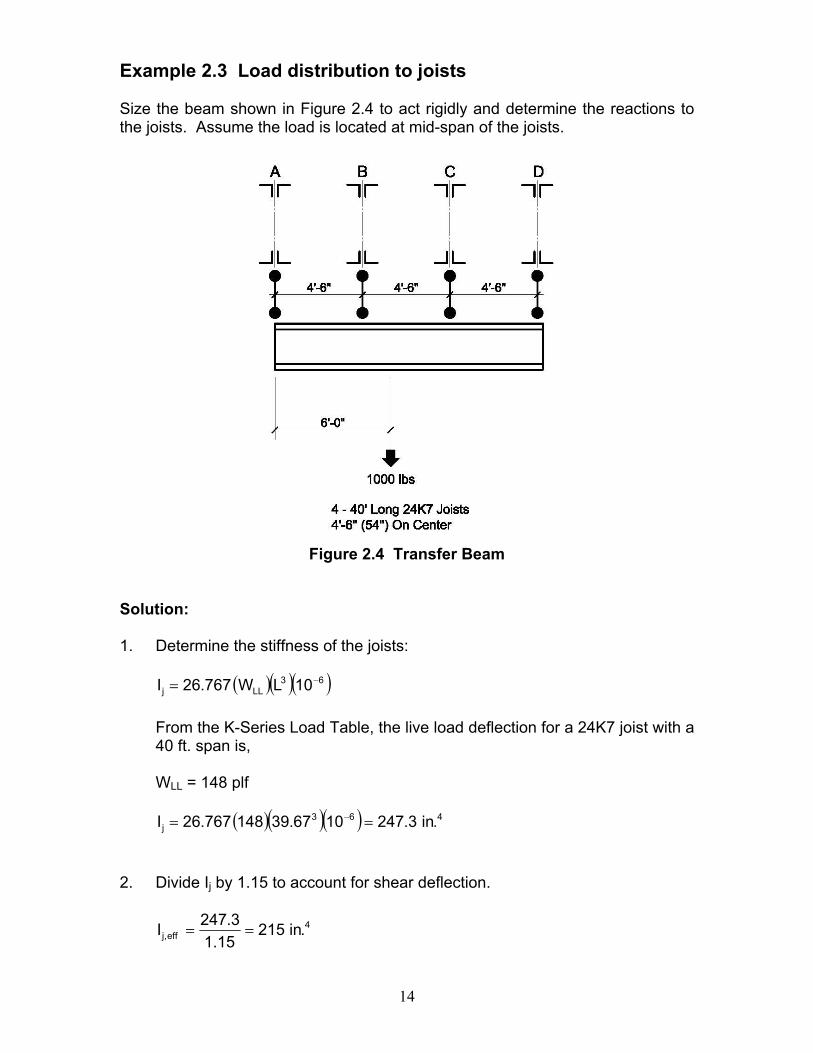
Example 2.3 Load distribution to joists Size the beam shown in Figure 2.4 to act rigidly and determine the reactions to the joists. Assume the load is located at mid-span of the joists.
Figure 2.4 Transfer Beam
Solution: 1. Determine the stiffness of the joists:
( )( )( )63LLj 10LW767.26I −=
From the K-Series Load Table, the live load deflection for a 24K7 joist with a 40 ft. span is,
WLL = 148 plf
( )( )( ) 463
j .in3.2471067.39148767.26I == − 2. Divide Ij by 1.15 to account for shear deflection.
4eff,j .in215
15.13.247I ==
15
3eff,j
eff,j
3 LEI48
EI48PLPPK ==
∆=
( )( )( )( )( )[ ]
.ink77.21267.39
2152900048K 3 ==
Determine the beam size necessary to distribute the load to the four joists:
Try W16X26 Ix = 301 in.4
( )( ) ( )( )( )
144 .in0062.0
3012900045477.2
EI4SK −===β
Check if spacing, .in8.1264
S =βπ
<
S = 54 in. < 126.8 in. Therefore, OK
Check the length of beam < 1/β
L = 13.5 ft. = 162 in.
1/β = 1/0.0062 = 161.5 in.
162 in. ~ 161.5 in. Therefore, OK
Therefore, the beam may be assumed to act as a rigid body in delivering load to the joists.
3. Solve for the reaction at each joist:
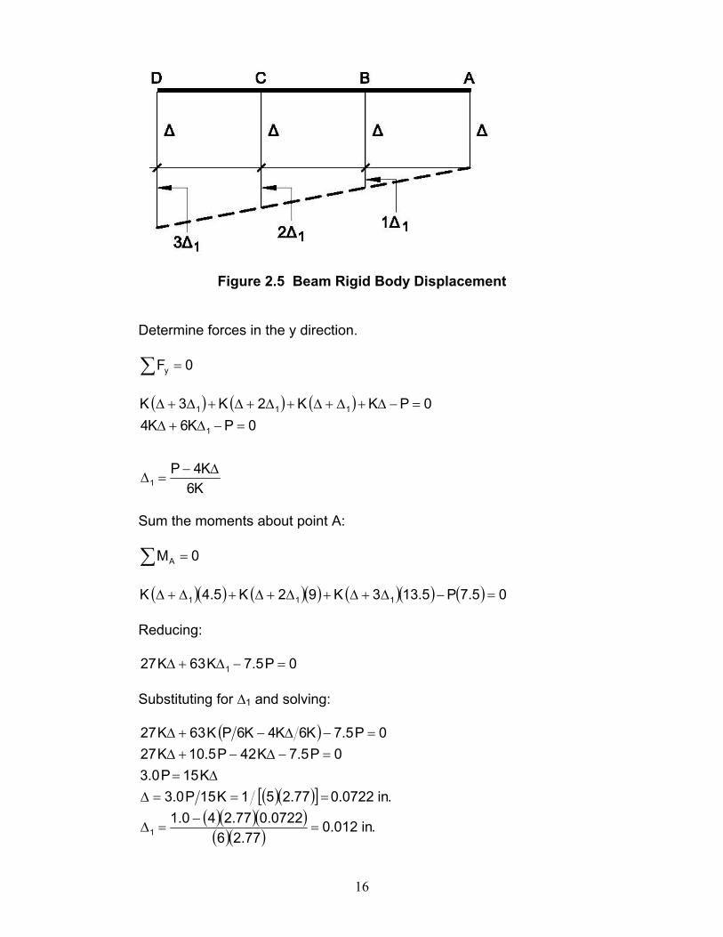
The reaction at the joist is equal to the deflection at the joist multiplied by its stiffness. The rigid body displacement of the beam is shown in Figure 2.5. Based on the rigid body displacement of the beam, each joist will have a force equal to the stiffness of the joist, K, times the displacement of the joist.
16
Figure 2.5 Beam Rigid Body Displacement
Determine forces in the y direction.
∑ = 0Fy
( ) ( ) ( )
K6K4P
0PK6K40PKK2K3K
1
1
111
∆−=∆
=−∆+∆
=−∆+∆+∆+∆+∆+∆+∆
Sum the moments about point A:
∑ = 0MA
( )( ) ( )( ) ( )( ) ( ) 05.7P5.133K92K5.4K 111 =−∆+∆+∆+∆+∆+∆
Reducing:
0P5.7K63K27 1 =−∆+∆
Substituting for ∆1 and solving:
( )
( )( )[ ]( )( )( )( )( ) .in012.0
77.260722.077.240.1
.in0722.077.251K15P0.3K15P0.3
0P5.7K42P5.10K270P5.7K6K4K6PK63K27
1 =−
=∆
===∆∆=
=−∆−+∆=−∆−+∆
17
Solving for the reactions:
RA =2.77(0.0722) = 0.20 kips RB =2.77[0.0722 + 0.012] = 0.23 kips RC =2.77[0.0722 + (2)(0.012)] = 0.27 kips RD =2.77[0.0722 + (3)(0.012)] = 0.30 kips
Adding the tributary weight of the beam the maximum reactions are:
RA = 0.26 kips RB = 0.35 kips RC = 0.39 kips RD = 0.36 kips
B) Adding New Joists or Beams Consider adding new joists or wide flange beams to support added loads before using expensive reinforcement solutions. Of major concern in adding joists or beams are existing interferences. It may not be practical to add members because piping, electrical conduits, or other interferences may have to be removed or relocated at a greater expense than reinforcing. If joists are to be added, consideration must be given to camber and to the lateral stability of the joist top chord. In order to insert new joists or beams under an existing floor or roof deck it may be necessary to specify reduced or “no camber” for the added joists. For situations involving adding new K-Series joists, seat depths should be ordered to a 2 in. height, and then shimmed to facilitate erection. A preferred way to provide supplemental joists is to have the joist manufacturer provide a center splice so that two individual pieces can be installed, and then bolted at the center. It is often difficult to attach the deck to a new joist that has been added to an existing structure. With a concrete slab on top of the deck, pins can be shot through the underside of the joist top chords, through the deck and into the concrete. Sometimes the joist top chords cannot be attached to the deck. These joists must be designed as laterally unsupported between rows of bridging. In these cases, additional rows of bridging may be required, and or, the top chord size increased to provide the necessary lateral stability.
18
C) Reinforcing Existing Joists The type of reinforcement, and details to be used, are dependent on the geometry of the joist to be strengthened. The following items have a major impact on the solution for both chord and web reinforcement:
1. Rod web members 2. Crimped angle web members (many crimped web joists have rod end
diagonals) 3. Web angles welded to the sides of the chords 4. Geometry of the chords 5. Chord and web yield strength
Some or all of the joist web members may have been originally sized sufficiently to accommodate the new loading requirements but the weld may have only been sized for the original design loading. Although the actual weld placed on the web during the fabrication process may be larger than the design requirement, there is no guarantee that this actually occurred. Therefore, if the new stress level in the existing welds is higher than what the engineer deems as adequate, additional weld may be required. There may be additional locations where weld can be added to the webs to achieve the required capacity. Consider also that it may only be possible to reinforce the chords and web members on only one side. This may be required when joists are adjacent to walls or other interferences. Particular attention must then be paid to eccentricities.
19
CHAPTER 3
DESIGN APPROACHES FOR STRENGTHENING JOISTS
There are two design approaches with respect to reinforcing individual joist members. Approach I: Ignore the existing strength of the member. Approach II: Make use of the strength of the existing member. Although Approach I is conservative, it avoids load distribution concerns between the reinforcing member and the existing member. This approach is not generally used for chord reinforcement. When using either approach, consider the fact that the cost of materials for reinforcing is almost insignificant to the cost of the field labor. Also, with either design approach, it is safest to reinforce the joist in the shored position. Welding can generate enough heat to cause a temporary loss of strength in the steel. This is particularly true if welds are made transverse to the axis of the member (transverse field welds should be avoided). With the loss of strength the member can sag excessively or even collapse, thus shoring should be placed tight against the joist being reinforced. It is also best to reinforce members with the dead and live loads removed. This can be done by calculating the amount of load present on the joist and then jacking the joist up to a calculated deflection that theoretically removes the load on the joist. In most cases jacks located at the panel points nearest the third points should be used. The designer is also cautioned to pay particular attention to eccentricities created by the reinforcing, and also to account for any shear lag effects in the design. APPROACH I If Approach I is used, there are no special considerations that need to be addressed. Simply design the reinforcing members to carry the total load. APPROACH II Terminology and terms used in the following discussion: Ae = area of existing member, in.2 Afr = area of the furnished reinforcing, in.2
20
Ar = required area of reinforcing, in.2 At = area of existing member plus the area of the furnished reinforcing, in.2 Atr = total area required (existing member and required reinforcing), in.2 Fye = specified minimum yield stress of existing member, ksi. Po = original force for the existing member (original design force), kips. Pp = preload in the existing member at the time of reinforcing, kips. Pr = force in the reinforcing member, kips. Pt = required strength, kips. Prw = required strength in the reinforcing member weld, kips. fp = stress from preload in the existing member, ksi. For Approach II, it is assumed that applied forces are distributed between the existing member and the reinforcing member in direct proportion to their areas. Any preload force in the existing member must be considered. If the joists are shored and jacked up to remove the existing load, then the preload is zero, otherwise the preload can be calculated based on the load present at the time of reinforcing. Shoring and placement of the jacks is the responsibility of the Specifying Professional. Design of reinforcing for tension members (Approach II): 1. Determine the total area required, Atr.
If the force in the existing member is limited to the original required strength in the member, the following equation applies. Using this procedure the initial welds, as provided by the joist manufacturer, are not increased.
( ) otr
eptp P
AAPPP ≤⎟⎟
⎠
⎞⎜⎜⎝
⎛−+ Eq. 3-1
Thus,
( )( ) e
po
pttr A
PPPP
A−−
= Eq. 3-2
It should be noted that the equation assumes that the existing steel and the reinforcing steel both have equal yield strength. There are several design procedures to accommodate the fact that the yield strengths of the two materials may not be equal. These include:
• Assume both materials have the same yield strength as the yield strength of the lowest material used. This is the most conservative method.
• Use the actual yield strength of each material in the design. Allow each material to achieve the full allowed stress level.
21
In addition, for welded connections, matching weld metal may be a consideration if the yield strength is less than 36 ksi (e.g. S-Series joists fabricated from A7 steel with a yield strength of 33 ksi).
2. The required area of reinforcing equals
etrr AAA −= Eq. 3-3 3. The force in the reinforcing member equals
( )ptt
frr PP
AAP −⎟⎟
⎠
⎞⎜⎜⎝
⎛= Eq. 3-4
Alternately, the weld on the existing member can be reinforced to take the entire axial load, provided an adequate force path exists to transfer the force in the reinforcing member to the weld.
As an alternate to the above, for tension members only, an ultimate strength approach could be used, wherein, the yield strength of the composite section is used to resist the tension load.
Design of reinforcing for compression members (Approach II): 1. Select a trial reinforcing member. 2. Check the buckling strength of the composite member. If a preload force
exists, first determine the magnitude of the compressive stress in the existing member due to the preload, fp. For the buckling check, use Fy as the minimum of (Fye - fp), and Fy of the reinforcing member.
3. Design the weld for the reinforcing member. The force in the weld is
( )ptt
frrw PP
AAP −⎟⎟
⎠
⎞⎜⎜⎝
⎛= Eq. 3-5
Or, as previously mentioned, the weld on the existing member can be reinforced to take the entire axial load provided an adequate force path exists to transfer the force in the reinforcing member to the weld.
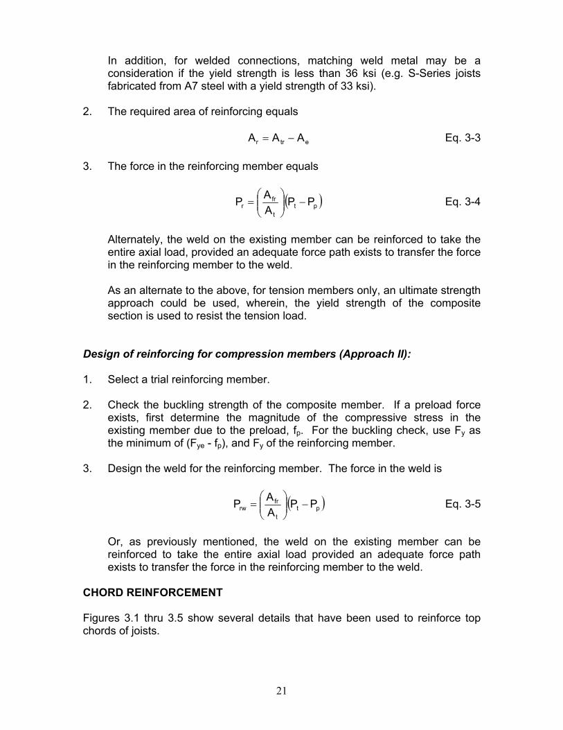
CHORD REINFORCEMENT Figures 3.1 thru 3.5 show several details that have been used to reinforce top chords of joists.
22
Figure 3.1 Top Chord Reinforcement - Rods
Figure 3.2 Top Chord Reinforcement - Plates
Figure 3.3 Top Chord Reinforcement - Angles
23
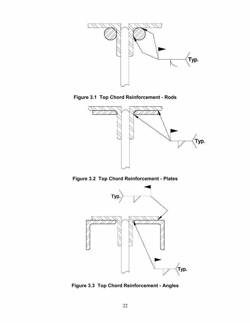
Figure 3.4 Top Chord Reinforcement - Angles
Figure 3.5 Top Chord Reinforcement - Rods
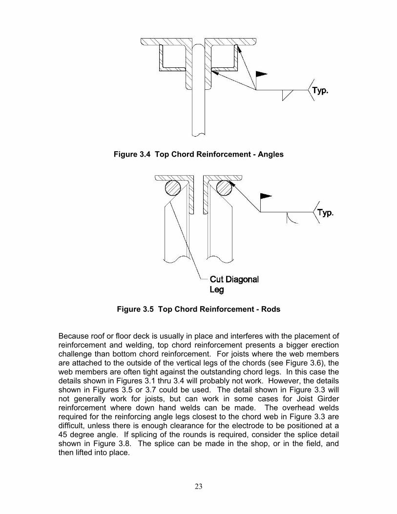
Because roof or floor deck is usually in place and interferes with the placement of reinforcement and welding, top chord reinforcement presents a bigger erection challenge than bottom chord reinforcement. For joists where the web members are attached to the outside of the vertical legs of the chords (see Figure 3.6), the web members are often tight against the outstanding chord legs. In this case the details shown in Figures 3.1 thru 3.4 will probably not work. However, the details shown in Figures 3.5 or 3.7 could be used. The detail shown in Figure 3.3 will not generally work for joists, but can work in some cases for Joist Girder reinforcement where down hand welds can be made. The overhead welds required for the reinforcing angle legs closest to the chord web in Figure 3.3 are difficult, unless there is enough clearance for the electrode to be positioned at a 45 degree angle. If splicing of the rounds is required, consider the splice detail shown in Figure 3.8. The splice can be made in the shop, or in the field, and then lifted into place.

24
Figure 3.6 Angle Interference with Top Chord Reinforcement
Figure 3.7 Top Chord Reinforcement Requiring Notch
25
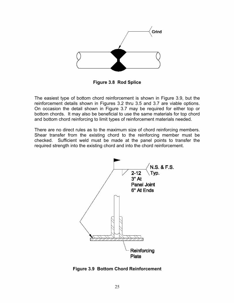
Figure 3.8 Rod Splice
The easiest type of bottom chord reinforcement is shown in Figure 3.9, but the reinforcement details shown in Figures 3.2 thru 3.5 and 3.7 are viable options. On occasion the detail shown in Figure 3.7 may be required for either top or bottom chords. It may also be beneficial to use the same materials for top chord and bottom chord reinforcing to limit types of reinforcement materials needed. There are no direct rules as to the maximum size of chord reinforcing members. Shear transfer from the existing chord to the reinforcing member must be checked. Sufficient weld must be made at the panel points to transfer the required strength into the existing chord and into the chord reinforcement.
Figure 3.9 Bottom Chord Reinforcement
26
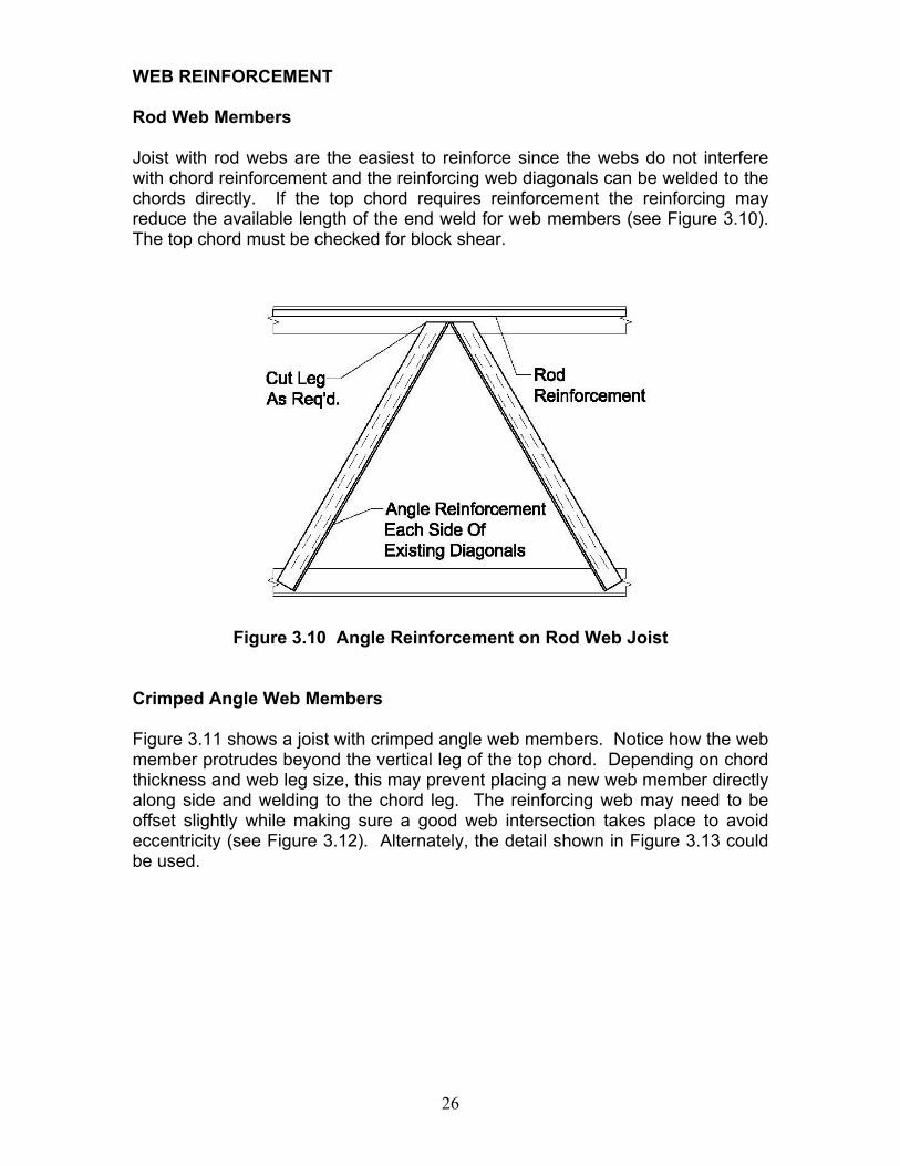
WEB REINFORCEMENT Rod Web Members Joist with rod webs are the easiest to reinforce since the webs do not interfere with chord reinforcement and the reinforcing web diagonals can be welded to the chords directly. If the top chord requires reinforcement the reinforcing may reduce the available length of the end weld for web members (see Figure 3.10). The top chord must be checked for block shear.
Figure 3.10 Angle Reinforcement on Rod Web Joist
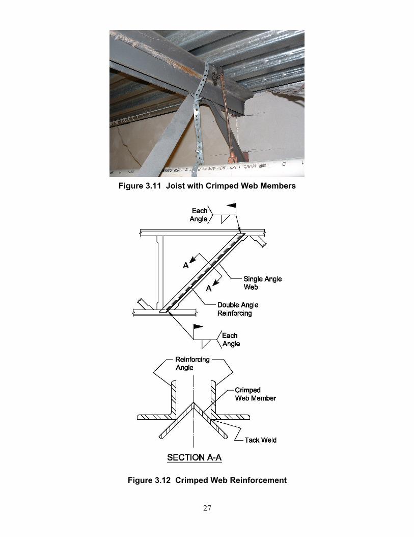
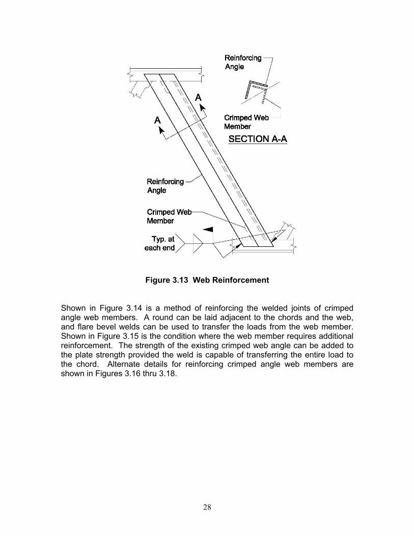
Crimped Angle Web Members Figure 3.11 shows a joist with crimped angle web members. Notice how the web member protrudes beyond the vertical leg of the top chord. Depending on chord thickness and web leg size, this may prevent placing a new web member directly along side and welding to the chord leg. The reinforcing web may need to be offset slightly while making sure a good web intersection takes place to avoid eccentricity (see Figure 3.12). Alternately, the detail shown in Figure 3.13 could be used.
27
Figure 3.11 Joist with Crimped Web Members
Figure 3.12 Crimped Web Reinforcement
28
Figure 3.13 Web Reinforcement
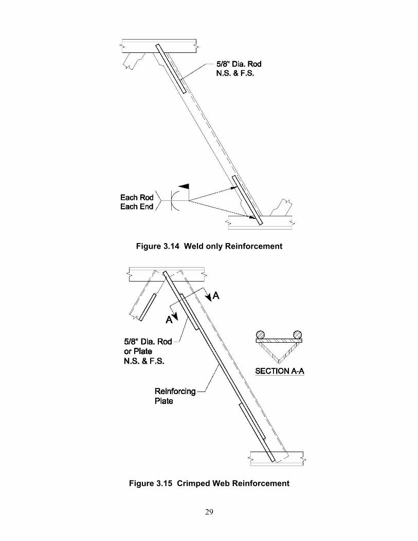
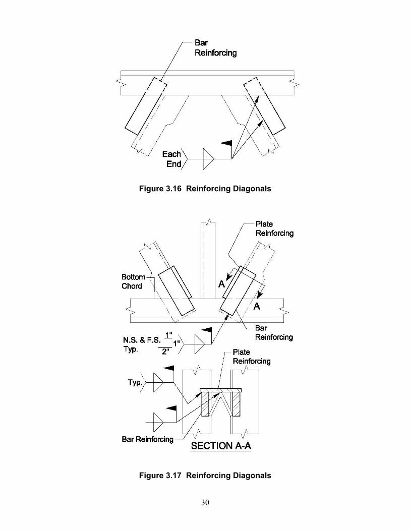
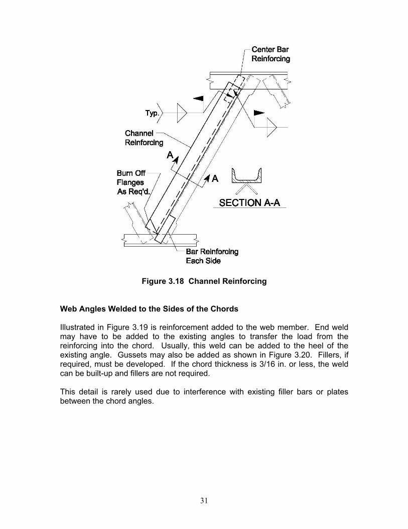
Shown in Figure 3.14 is a method of reinforcing the welded joints of crimped angle web members. A round can be laid adjacent to the chords and the web, and flare bevel welds can be used to transfer the loads from the web member. Shown in Figure 3.15 is the condition where the web member requires additional reinforcement. The strength of the existing crimped web angle can be added to the plate strength provided the weld is capable of transferring the entire load to the chord. Alternate details for reinforcing crimped angle web members are shown in Figures 3.16 thru 3.18.
29
Figure 3.14 Weld only Reinforcement
Figure 3.15 Crimped Web Reinforcement
30
Figure 3.16 Reinforcing Diagonals
Figure 3.17 Reinforcing Diagonals
31
Figure 3.18 Channel Reinforcing
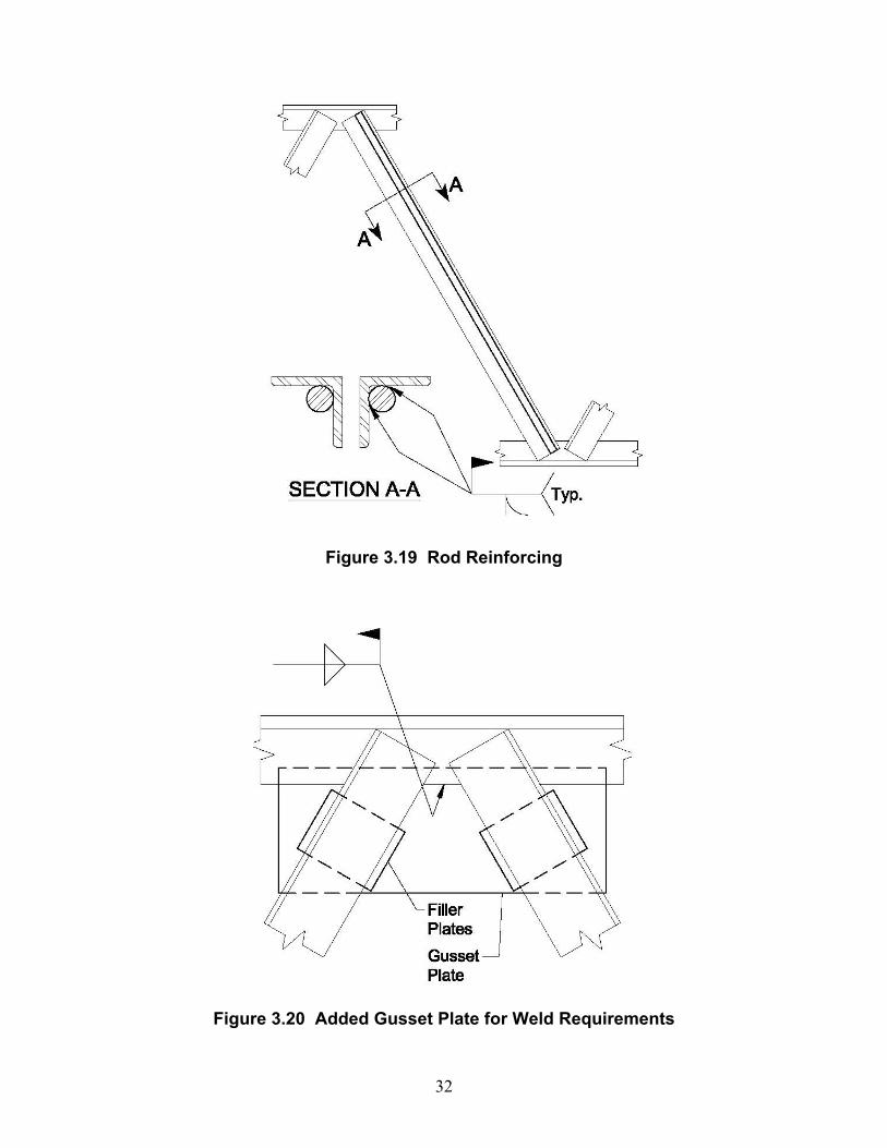
Web Angles Welded to the Sides of the Chords Illustrated in Figure 3.19 is reinforcement added to the web member. End weld may have to be added to the existing angles to transfer the load from the reinforcing into the chord. Usually, this weld can be added to the heel of the existing angle. Gussets may also be added as shown in Figure 3.20. Fillers, if required, must be developed. If the chord thickness is 3/16 in. or less, the weld can be built-up and fillers are not required. This detail is rarely used due to interference with existing filler bars or plates between the chord angles.
32
Figure 3.19 Rod Reinforcing
Figure 3.20 Added Gusset Plate for Weld Requirements
33
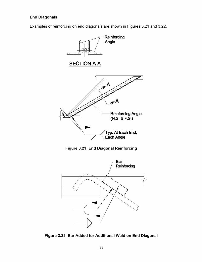
End Diagonals Examples of reinforcing on end diagonals are shown in Figures 3.21 and 3.22.
Figure 3.21 End Diagonal Reinforcing
Figure 3.22 Bar Added for Additional Weld on End Diagonal
34
Example 3.1 Strengthening a K-Series joist with crimped angle
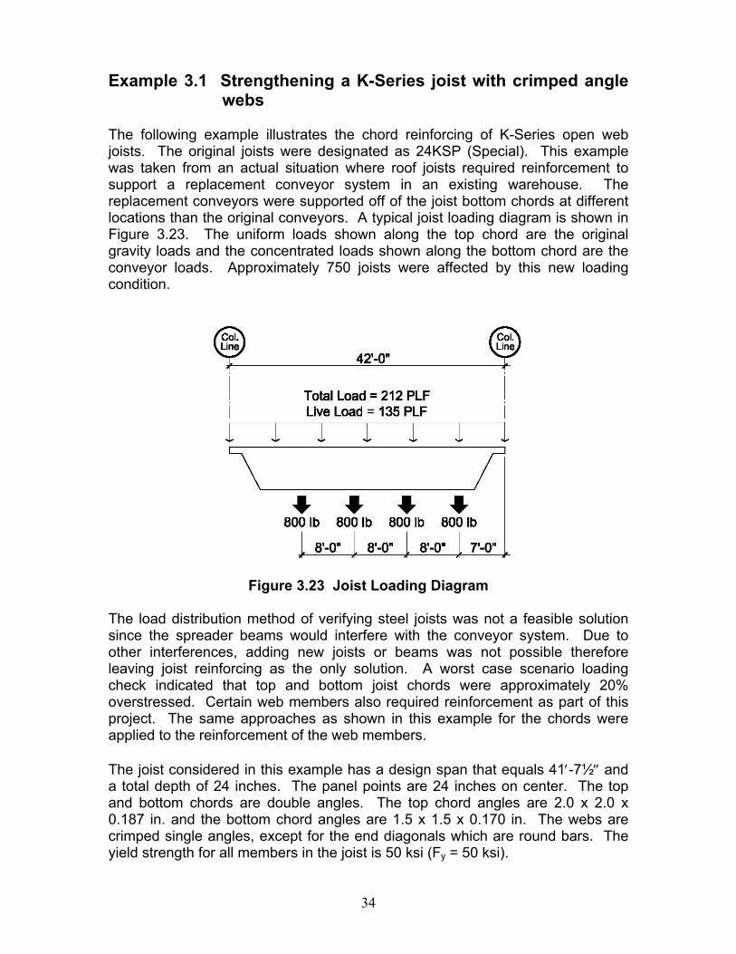
webs The following example illustrates the chord reinforcing of K-Series open web joists. The original joists were designated as 24KSP (Special). This example was taken from an actual situation where roof joists required reinforcement to support a replacement conveyor system in an existing warehouse. The replacement conveyors were supported off of the joist bottom chords at different locations than the original conveyors. A typical joist loading diagram is shown in Figure 3.23. The uniform loads shown along the top chord are the original gravity loads and the concentrated loads shown along the bottom chord are the conveyor loads. Approximately 750 joists were affected by this new loading condition.
Figure 3.23 Joist Loading Diagram
The load distribution method of verifying steel joists was not a feasible solution since the spreader beams would interfere with the conveyor system. Due to other interferences, adding new joists or beams was not possible therefore leaving joist reinforcing as the only solution. A worst case scenario loading check indicated that top and bottom joist chords were approximately 20% overstressed. Certain web members also required reinforcement as part of this project. The same approaches as shown in this example for the chords were applied to the reinforcement of the web members. The joist considered in this example has a design span that equals 41′-7½″ and a total depth of 24 inches. The panel points are 24 inches on center. The top and bottom chords are double angles. The top chord angles are 2.0 x 2.0 x 0.187 in. and the bottom chord angles are 1.5 x 1.5 x 0.170 in. The webs are crimped single angles, except for the end diagonals which are round bars. The yield strength for all members in the joist is 50 ksi (Fy = 50 ksi).
35
The required axial force in the top chord and bottom chords was determined to be 35.2 kips, whereas the allowable top and bottom chord forces obtained from the joist manufacturer were 29.6 kips and 28.9 kips, respectively. The dead load in the chords at the time of reinforcing was 6.2 kips. Since the joists were originally designed using the Allowable Stress Design (ASD) method, those same procedures were used to determine the required reinforcement. Approach II was used. The new concentrated loads were not located at the bottom chord panel points, thus in addition to the top and bottom chord reinforcement design, struts were added to prevent bottom chord bending. See Example 3.6 for the procedure to design a new strut. Top Chord Reinforcing Design Approach: 1. Select a trial reinforcing member. 2. Determine the composite section properties of the reinforcing member and
the existing member. 3. Check overall chord buckling. First determine the magnitude of the
compressive stress in the existing member due to the preload, fp. For the buckling check, use Fy as the minimum of (Fye – fp), and Fy of the reinforcing member.
4. Design the weld size and length for the reinforcing member. The force in
the weld is:
( )ptt
frrw PP
AAP −⎟⎟
⎠
⎞⎜⎜⎝
⎛= Eq. 3-5
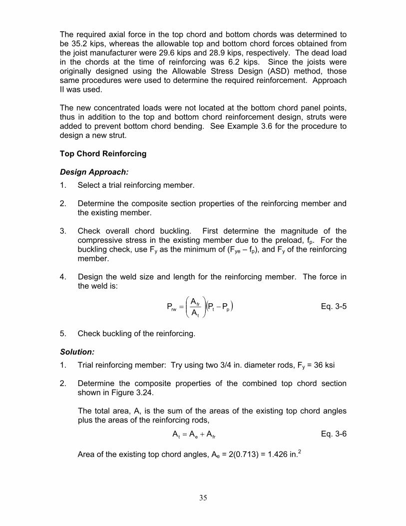
5. Check buckling of the reinforcing. Solution: 1. Trial reinforcing member: Try using two 3/4 in. diameter rods, Fy = 36 ksi 2. Determine the composite properties of the combined top chord section
shown in Figure 3.24. The total area, A, is the sum of the areas of the existing top chord angles plus the areas of the reinforcing rods,
fret AAA += Eq. 3-6 Area of the existing top chord angles, Ae = 2(0.713) = 1.426 in.2
36
Area of furnished reinforcing, ( ) 22fr .in884.0442.024d2A ==π=
2
t .in31.2884.0426.1A =+=
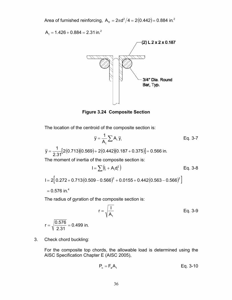
Figure 3.24 Composite Section
The location of the centroid of the composite section is:
∑= iit
yAA1y Eq. 3-7
( )( ) ( )( )[ ] .in566.0375.0187.0442.02569.0713.0231.21y =++=
The moment of inertia of the composite section is:
( )∑ += 2iii dAII Eq. 3-8
( ) ( )[ ]4
22
.in576.0
566.0563.0442.00155.0566.0509.0713.0272.02I
=
−++−+=
The radius of gyration of the composite section is:
tAIr = Eq. 3-9
.in499.031.2
576.0r ==
3. Check chord buckling:
For the composite top chords, the allowable load is determined using the AISC Specification Chapter E (AISC 2005),
tac AFP = Eq. 3-10
37
where:
Pc is the allowable compressive strength, cnP Ω , kips Fa is the allowable compressive stress, ccrF Ω , ksi Safety factor, 67.1c =Ω
Determine the yield stress to be used for the reinforcement design:
Preload, Pp = 6.2 kips
( )( ) ksi35.4713.022.6fp ==
Yield stress to be used is the minimum of:
Fye – fp = 50 - 4.35 = 45.65 ksi, and Fy = 36 ksi for the rods.
Thus, use 36 ksi.
When 0.1QFE45.0
tb
sy
=≤ (AISC E7-10)
0.1Q77.1236
2900045.0FE45.070.10
187.00.2
sy
===≤=
When yFF
cry
F658.0FFE71.4
rKL
e
y
⎥⎥⎦
⎤
⎢⎢⎣
⎡=≤ (AISC E3-2)
When ecry
F877.0FFE71.4
rKL
=> (AISC E3-3)
2
2
e
rKL
EF
⎟⎠⎞
⎜⎝⎛
π= (AISC E3-4)
Compute the slenderness ratio of the composite section. The vertical web members provided between the panel points, brace the chord. Therefore, use an unsupported length, L= 24 in. and an effective length factor K = 1.0.
68.13336
2900071.410.48499.024
rL
=<==
38
( ) ksi73.123
499.02429000F 2
2
e =
⎟⎠⎞
⎜⎝⎛
π=
ksi87.3136658.0F 73.12336
cr =⎥⎦
⎤⎢⎣
⎡=
The available axial compressive stress is:
ksi09.19FFc
cra =
Ω=
And, the available compressive force is:
( )( ) requiredkips2.35kips09.4431.209.19Pc >== Therefore, OK 4. Design the welds:
The total force in the welds determined by Equation 3-5 is:
( ) kips10.112.62.3531.2
884.0Prw =−⎟⎠⎞
⎜⎝⎛=
Alternately, each of the 3/4 in. diameter rods has an allowable force of (19.09)(0.442) = 8.44 kips. This force will be used for the weld design.
The joint between the rod and angle will be a partial-joint-penetration groove weld and will have an effective throat thickness of (5/16) times the rod radius (see AISC Specification Table J2.2 for a Flare Bevel Groove weld), thus the effective throat equals 0.117 in.
The allowable shear per weld using E70 electrodes (FEXX = 70 ksi) is determined from the AISC Specification Table J2.5, Available Strength of Welded Joints as follows:
( )w
EXXew
F60.0tFΩ
= Eq. 3-11
( )( ) .in/kips46.200.2
7060.0117.0Fw ==
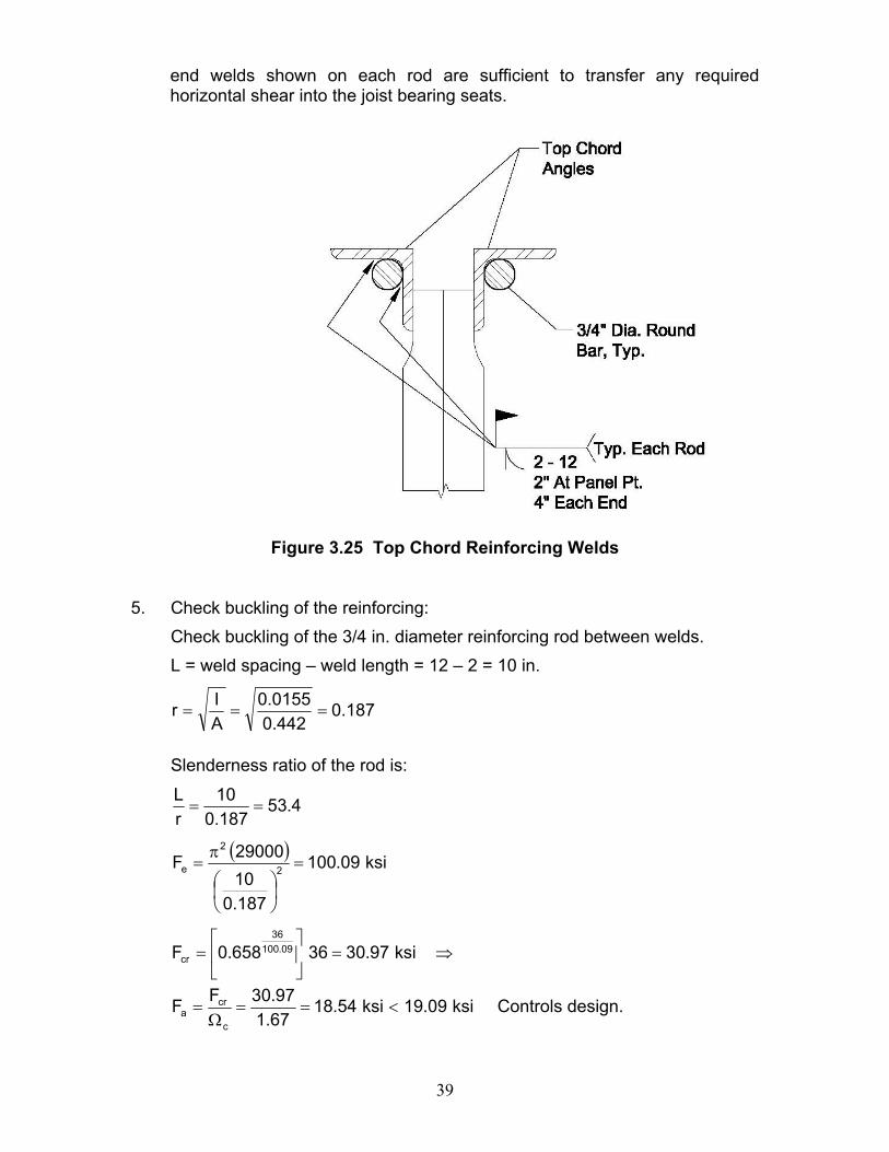
The total length of weld required to develop the force in each rod equals 8.44/2.46 = 3.43 in. The size and length of welds are shown in Figure 3.25. At each panel point location two 2 in. long welds are shown for each reinforcing rod to angle connection. Between panel points, the reinforcing rod is stitch welded 2 in. at 12 in. center-to-center. This pattern is used as a practical limitation to limit the slenderness ratio between connectors. By observation, the 4 inch
39
end welds shown on each rod are sufficient to transfer any required horizontal shear into the joist bearing seats.
Figure 3.25 Top Chord Reinforcing Welds
5. Check buckling of the reinforcing: Check buckling of the 3/4 in. diameter reinforcing rod between welds. L = weld spacing – weld length = 12 – 2 = 10 in.
187.0442.0
0155.0AIr ===
Slenderness ratio of the rod is:
4.53187.010
rL
==
( ) ksi09.100
187.01029000F 2
2
e =
⎟⎠⎞
⎜⎝⎛
π=
⇒=⎥⎦
⎤⎢⎣
⎡= ksi97.3036658.0F 09.100
36
cr
ksi09.19ksi54.1867.197.30FF
c
cra <==
Ω= Controls design.
40
And, the available compressive force is:
( )( ) requiredkips2.35kips83.4231.254.18Pc >== Therefore, OK The required length and position of the bottom chord reinforcing has not been shown here. It can be determined in a manner as is done for cover plating a steel beam; however, the reinforcement should always be extended beyond the next panel point closer to the end of the joist. This will ensure that the reinforcement is developed for the required force. This is necessary because unlike a beam, the required forces enter the chords at the major panel points of the joist. Bottom Chord Reinforcing
Total area required = ( )( ) e
po
pttr A
PPPP
A−−
=
where:
Pt = 35.2 kips Pp = 6.2 kips Po = 28.9 kips
Ae = 0.962 in.2 (area of original two 1.50 x1.50 x 0.170 angles).
Thus,
( )( ) ( ) 2
tr .in229.1962.02.69.282.62.35A =
−−
=
The required area of reinforcing equals 2
etrr .in267.0962.0229.1AAA =−=−=
The total width of the bottom chord including the gap between the angles is approximately 4 in. To allow a down hand fillet weld to be used, select a 5 in. wide plate. Using a 3/16 in. thick plate, the area of the plate provided is:
( ) 2fr .in938.05
163A =⎟⎠⎞
⎜⎝⎛= 0.938 in.2 > 0.267 in.2 Therefore, OK
The force in the reinforcing member is:
( ) ( ) kips32.142.62.35900.1938.0PP
AAP pt
t
frr =−⎟
⎠⎞
⎜⎝⎛=−⎟⎟
⎠
⎞⎜⎜⎝
⎛=
41
Check the stress in reinforcing member: F = P/A =14.32/0.938 = 15.27 ksi
Therefore, by observation A36 material is ok.
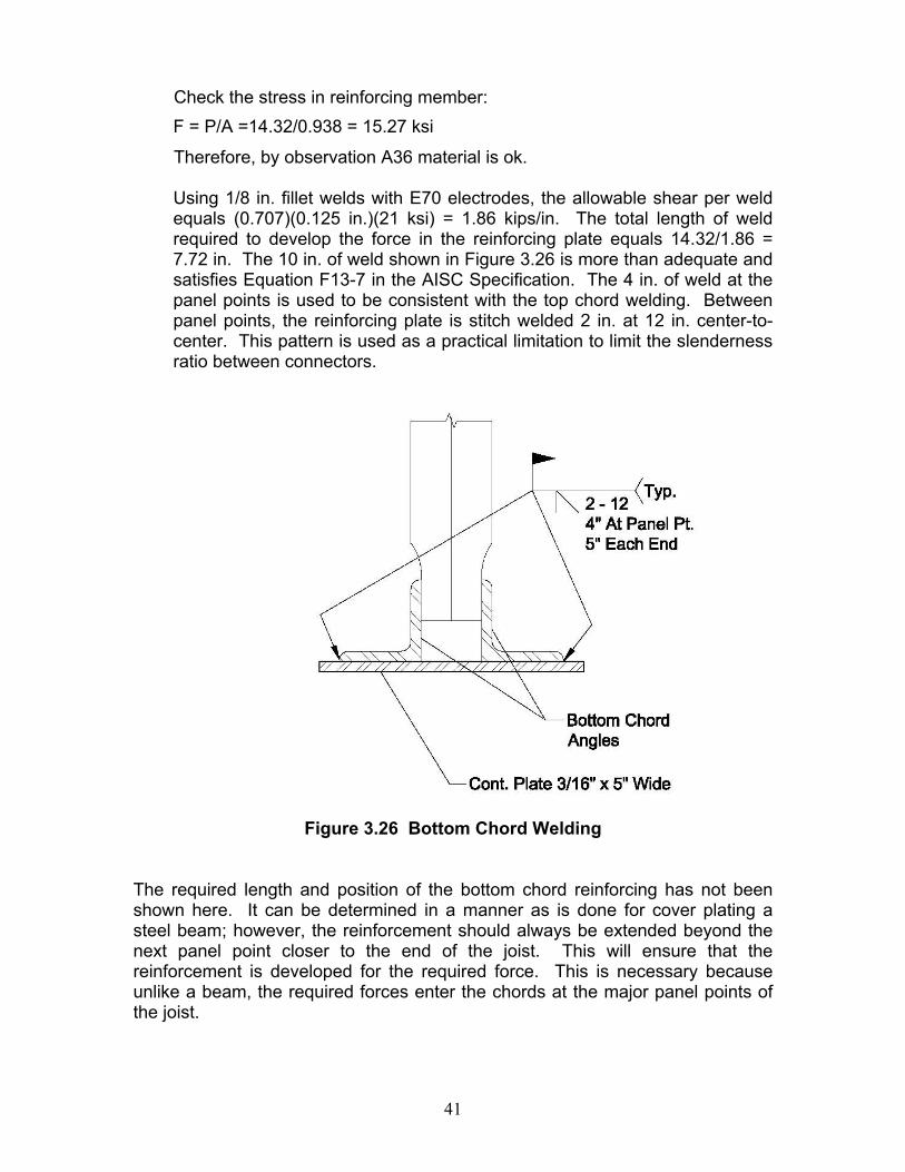
Using 1/8 in. fillet welds with E70 electrodes, the allowable shear per weld equals (0.707)(0.125 in.)(21 ksi) = 1.86 kips/in. The total length of weld required to develop the force in the reinforcing plate equals 14.32/1.86 = 7.72 in. The 10 in. of weld shown in Figure 3.26 is more than adequate and satisfies Equation F13-7 in the AISC Specification. The 4 in. of weld at the panel points is used to be consistent with the top chord welding. Between panel points, the reinforcing plate is stitch welded 2 in. at 12 in. center-to-center. This pattern is used as a practical limitation to limit the slenderness ratio between connectors.
Figure 3.26 Bottom Chord Welding
The required length and position of the bottom chord reinforcing has not been shown here. It can be determined in a manner as is done for cover plating a steel beam; however, the reinforcement should always be extended beyond the next panel point closer to the end of the joist. This will ensure that the reinforcement is developed for the required force. This is necessary because unlike a beam, the required forces enter the chords at the major panel points of the joist.
42
Web Reinforcing
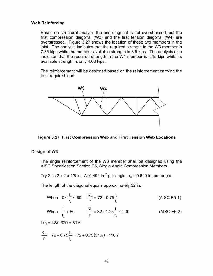
Based on structural analysis the end diagonal is not overstressed, but the first compression diagonal (W3) and the first tension diagonal (W4) are overstressed. Figure 3.27 shows the location of these two members in the joist. The analysis indicates that the required strength in the W3 member is 7.35 kips while the member available strength is 3.5 kips. The analysis also indicates that the required strength in the W4 member is 6.15 kips while its available strength is only 4.08 kips.
The reinforcement will be designed based on the reinforcement carrying the total required load.
Figure 3.27 First Compression Web and First Tension Web Locations
Design of W3
The angle reinforcement of the W3 member shall be designed using the AISC Specification Section E5, Single Angle Compression Members.
Try 2L’s 2 x 2 x 1/8 in. A=0.491 in.2 per angle. rx = 0.620 in. per angle.
The length of the diagonal equals approximately 32 in.
When xx rL75.072
rKL80
rL0 +=≤≤ (AISC E5-1)
When 200rL25.132
rKL80
rL
xx
≤+=> (AISC E5-2)
L/rx = 32/0.620 = 51.6
( ) 7.1106.5175.072rL75.072
rKL
x
=+=+=
43
Determine whether the single angle unstiffened elements are slender. If so, they need to be designed using the AISC Specification Section E7, Members with Slender Elements.
When 0.1QFE45.0
tb
sy
=≤ (AISC E7-10)
When EF
tb76.034.1Q
FE91.0
tb
FE45.0 y
syy
⎟⎠⎞
⎜⎝⎛−=≤< (AISC E7-11)
83.2536
2900091.016125.0277.12
362900045.0 =≤=<=
912.029000
36125.0276.034.1Qs =⎟
⎠⎞
⎜⎝⎛−=
Since Qs < 1.0 the the angles are considered slender.
When yF
QF
cry
F658.0QFQFE71.4
rKL
e
y
⎥⎥⎦
⎤
⎢⎢⎣
⎡=≤ (AISC E7-2)
When ecry
F877.0FQFE71.4
rKL
=> (AISC E7-3)
( )( ) 98.13936912.0
2900071.47.110r
KL=<=
( )( )
ksi36.237.110
29000F 2
2
e =π
=
( )( )( )
ksi23.1836658.0912.0F 36.2336912.0
cr =⎥⎦
⎤⎢⎣
⎡=
ksi92.10FFc
cra =
Ω=
And, the available force is:
( )( )( ) requiredkips35.7kips7.10491.092.102Pavailable >== Therefore, OK
Using a 1/8 in. fillet weld, the allowable strength per inch of weld equals (0.928)(2) = 1.86 kips/in.
Length required = 7.35/1.86 = 3.95 in. ≈ 4.0 in.
44
Design of W4
Determine Pn for the 2 x 2 x 1/8 in. angles:
For tensile yielding:
( )( )( ) kips35.35491.0362AFP gyn ===
kips17.2167.135.35PP
t
navailable ==
Ω=
For tensile rupture:
eun AFUP =
Worst case scenario U = 0.6 (from AISC Specification Table D3.1)
( )( )( )( ) kips17.34491.0586.02Pn ==
kips09.1700.217.34PP
t
navailable ==
Ω= (controls) > 6.15 kips Therefore, OK
45
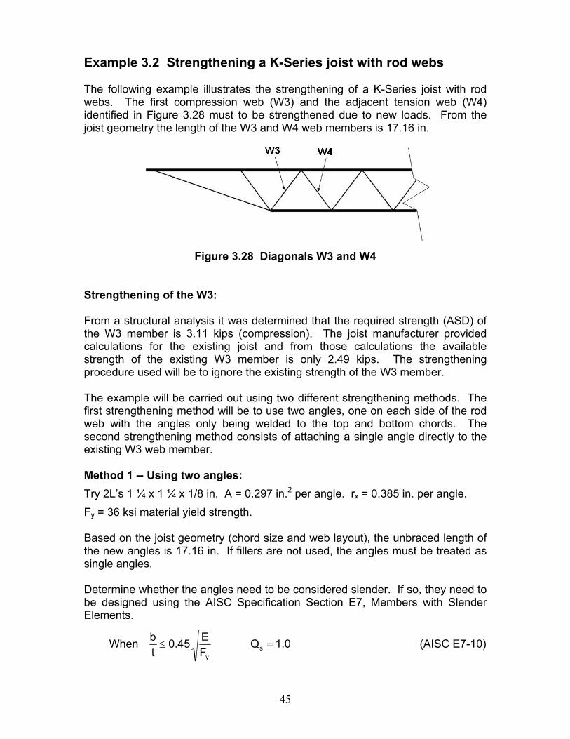
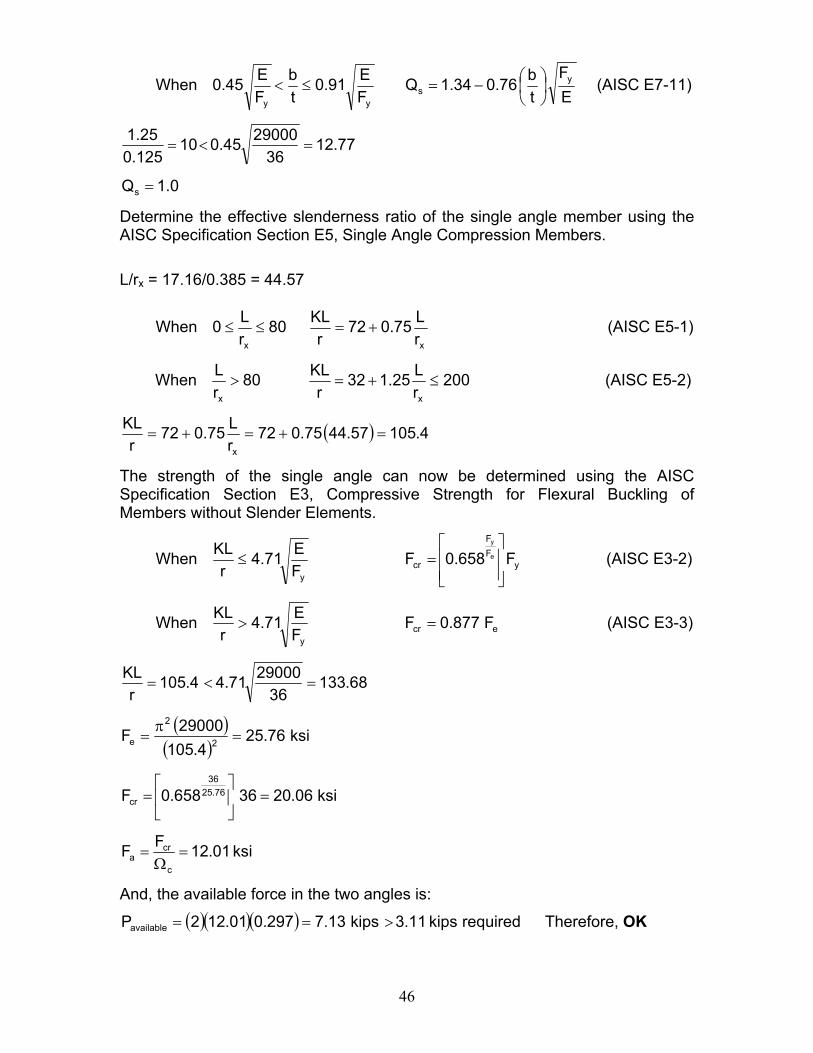
Example 3.2 Strengthening a K-Series joist with rod webs The following example illustrates the strengthening of a K-Series joist with rod webs. The first compression web (W3) and the adjacent tension web (W4) identified in Figure 3.28 must to be strengthened due to new loads. From the joist geometry the length of the W3 and W4 web members is 17.16 in.
Figure 3.28 Diagonals W3 and W4
Strengthening of the W3: From a structural analysis it was determined that the required strength (ASD) of the W3 member is 3.11 kips (compression). The joist manufacturer provided calculations for the existing joist and from those calculations the available strength of the existing W3 member is only 2.49 kips. The strengthening procedure used will be to ignore the existing strength of the W3 member. The example will be carried out using two different strengthening methods. The first strengthening method will be to use two angles, one on each side of the rod web with the angles only being welded to the top and bottom chords. The second strengthening method consists of attaching a single angle directly to the existing W3 web member. Method 1 -- Using two angles: Try 2L’s 1 ¼ x 1 ¼ x 1/8 in. A = 0.297 in.2 per angle. rx = 0.385 in. per angle. Fy = 36 ksi material yield strength. Based on the joist geometry (chord size and web layout), the unbraced length of the new angles is 17.16 in. If fillers are not used, the angles must be treated as single angles. Determine whether the angles need to be considered slender. If so, they need to be designed using the AISC Specification Section E7, Members with Slender Elements.
When 0.1QFE45.0
tb
sy
=≤ (AISC E7-10)
46
When EF
tb76.034.1Q
FE91.0
tb
FE45.0 y
syy
⎟⎠⎞
⎜⎝⎛−=≤< (AISC E7-11)
77.1236
2900045.010125.025.1
=<=
0.1Qs =
Determine the effective slenderness ratio of the single angle member using the AISC Specification Section E5, Single Angle Compression Members. L/rx = 17.16/0.385 = 44.57
When xx rL75.072
rKL80
rL0 +=≤≤ (AISC E5-1)
When 200rL25.132
rKL80
rL
xx
≤+=> (AISC E5-2)
( ) 4.10557.4475.072rL75.072
rKL
x
=+=+=
The strength of the single angle can now be determined using the AISC Specification Section E3, Compressive Strength for Flexural Buckling of Members without Slender Elements.
When yFF
cry
F658.0FFE71.4
rKL
e
y
⎥⎥⎦
⎤
⎢⎢⎣
⎡=≤ (AISC E3-2)
When ecry
F877.0FFE71.4
rKL
=> (AISC E3-3)
68.13336
2900071.44.105r
KL=<=
( )( )
ksi76.254.105
29000F 2
2
e =π
=
ksi06.2036658.0F 76.2536
cr =⎥⎦
⎤⎢⎣
⎡=
ksi01.12FFc
cra =
Ω=
And, the available force in the two angles is:
( )( )( ) requiredkips11.3kips13.7297.001.122Pavailable >== Therefore, OK
47
Connection of the angles to the chords: Use a 1/8 in. fillet weld since the reinforcing angles will be the thinner members to be joined to the chord angles (AISC Specification Table J2.4 Minimum Size of Fillet Welds). The allowable shear per weld using E70 electrodes (FEXX = 70 ksi) is determined from the AISC Specification Table J2.5, Available Strength of Welded Joints as follows:
( )w
EXXew
F60.0tFΩ
= Eq. 3-11
( )( )( )( ) .in/kips856.100.2
7060.0125.0707.0Fw ==
The length of weld required for each angle, each end equals:
( )( ) .in838.0856.1211.3
F2PL
w
rweld ===
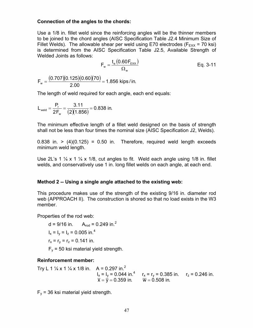
The minimum effective length of a fillet weld designed on the basis of strength shall not be less than four times the nominal size (AISC Specification J2, Welds). 0.838 in. > (4)(0.125) = 0.50 in. Therefore, required weld length exceeds minimum weld length. Use 2L’s 1 ¼ x 1 ¼ x 1/8, cut angles to fit. Weld each angle using 1/8 in. fillet welds, and conservatively use 1 in. long fillet welds on each angle, at each end. Method 2 -- Using a single angle attached to the existing web: This procedure makes use of the strength of the existing 9/16 in. diameter rod web (APPROACH II). The construction is shored so that no load exists in the W3 member. Properties of the rod web:
d = 9/16 in. Arod = 0.249 in.2 Ix = Iy = Iz = 0.005 in.4 rx = ry = rz = 0.141 in. Fy = 50 ksi material yield strength.
Reinforcement member: Try L 1 ¼ x 1 ¼ x 1/8 in. A = 0.297 in.2
Ix = Iy = 0.044 in.4 rx = ry = 0.385 in. rz = 0.246 in. .in508.0w.in359.0yx ===
Fy = 36 ksi material yield strength.
48
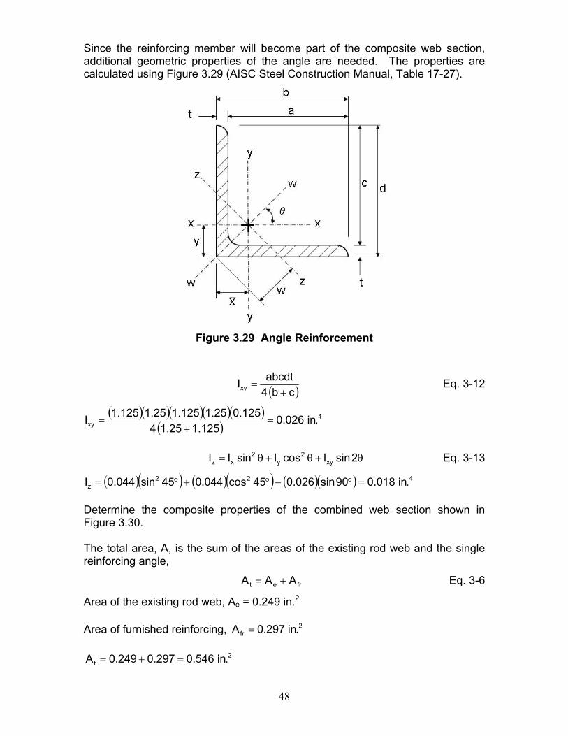
Since the reinforcing member will become part of the composite web section, additional geometric properties of the angle are needed. The properties are calculated using Figure 3.29 (AISC Steel Construction Manual, Table 17-27).
Figure 3.29 Angle Reinforcement
( )cb4abcdtIxy +
= Eq. 3-12
( )( )( )( )( )( )
4xy .in026.0
125.125.14125.025.1125.125.1125.1I =
+=
θ+θ+θ= 2sinIcosIsinII xy
2y
2xz Eq. 3-13
( )( ) ( )( ) ( )( ) 422z .in018.090sin026.045cos044.045sin044.0I =°−°+°=
Determine the composite properties of the combined web section shown in Figure 3.30. The total area, A, is the sum of the areas of the existing rod web and the single reinforcing angle,
fret AAA += Eq. 3-6
Area of the existing rod web, Ae = 0.249 in.2 Area of furnished reinforcing, 2
fr .in297.0A =
2t .in546.0297.0249.0A =+=
49
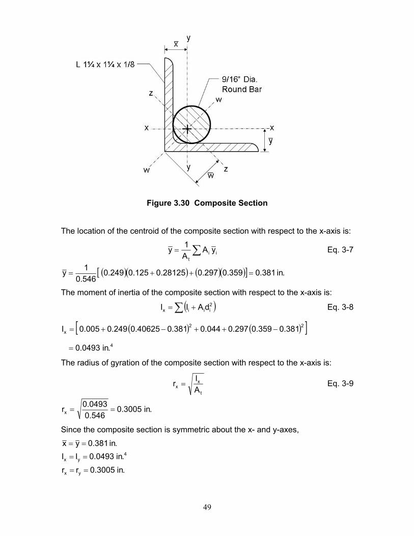
Figure 3.30 Composite Section
The location of the centroid of the composite section with respect to the x-axis is:
∑= iit
yAA1y Eq. 3-7
( )( ) ( )( )[ ] .in381.0359.0297.028125.0125.0249.0546.01y =++=
The moment of inertia of the composite section with respect to the x-axis is:
( )∑ += 2iiix dAII Eq. 3-8
( ) ( )[ ]4
22x
.in0493.0
381.0359.0297.0044.0381.040625.0249.0005.0I
=
−++−+=
The radius of gyration of the composite section with respect to the x-axis is:
t
xx A
Ir = Eq. 3-9
.in3005.0546.00493.0rx ==
Since the composite section is symmetric about the x- and y-axes,
.in3005.0rr.in0493.0II
.in381.0yx
yx
4yx
==
==
==
50
The location of the centroid of the composite section with respect to the z-axis is:
∑= iit
wAA1w Eq. 3-14
( )( ) ( )( )[ ] .in539.0508.0297.0398.0177.0249.0546.01w =++=
The moment of inertia of the composite section with respect to the z-axis is:
( )∑ += 2iiiz dAII Eq. 3-15
( ) ( )[ ]4
22z
.in0236.0
539.0508.0297.0018.0539.0575.0249.0005.0I
=
−++−+=
The radius of gyration of the composite section with respect to the z-axis is:
t
zz A
Ir = Eq. 3-16
.in208.0546.00236.0rz ==
Determine the strength of the combined section:
1.573005.0
16.17rLx
==
5.82208.016.17
rLz
== (controls)
From the AISC Steel Construction Manual Table 4-22, Available Critical Stress for Compression Members Fy = 36 ksi (AISC 2005),
ksi05.15FFc
cra =
Ω=
( )( ) kips22.8546.005.15AFP taavailable ===
The required strength, Pt = 3.11 kips
kips11.322.8PP tavailable >> Therefore, OK Use a 1 ¼ x 1 ¼ x 1/8 angle reinforcement along the full length of the 9/16 in. diameter rod web, W3.
51
Weld Design: The force in the weld is:
( )ptt
frrw PP
AAP −⎟⎟
⎠
⎞⎜⎜⎝
⎛= Eq. 3-5
( ) kips69.10.011.3546.0297.0Prw =−⎟
⎠⎞
⎜⎝⎛=
Design welds at the angle ends and at intermediate locations. The latter is based on buckling of the reinforcement. Assume the full force, Pt is in the rod web before its distribution between the angle and rod. The joint between the rod and angle will be a partial-joint-penetration groove weld and will have an effective throat thickness of (5/16) times the rod radius (see AISC Specification Table J2.2 for a Flare Bevel Groove weld), thus the effective throat equals 0.0879 in. The allowable shear per weld using E70 electrodes (FEXX = 70 ksi) is determined from the AISC Specification Table J2.5, Available Strength of Welded Joints as follows:
( )w
EXXew
F60.0tFΩ
= Eq. 3-11
( )( ) .in/kips85.100.2
7060.00879.0Fw ==
The total length of weld required to develop the force in the angle equals 1.69/1.85 = 0.91 in. ≈ 1.0 in. Check buckling of the reinforcing angle: Check buckling of the 1 ¼ x 1 ¼ x 1/8 angle between welds assuming they are placed only at the ends of the web reinforcement. Slenderness ratio of the angle is:
8.69246.016.17
rLz
==
From the AISC Steel Construction Manual Table 4-22, Available Critical Stress for Compression Members Fy = 36 ksi (AISC 2005),
ksi71.16FFc
cra =
Ω=
( )( ) kips96.4297.071.16AFP raavailable ===
52
The force in the reinforcing member is:
( )ptt
frr PP
AAP −⎟⎟
⎠
⎞⎜⎜⎝
⎛= Eq. 3-4
( ) kips69.10.011.3546.0297.0Pr =−⎟
⎠⎞
⎜⎝⎛=
kips69.196.4PP ravailable >> Therefore, intermediate welds are not required. Check the existing welds between the existing rod ends (W3) and the top and bottom chords. The required length of weld at each end equals:
.in68.185.111.3
FPL
w
tweld ===
From the original joist calculations the existing weld length is 1.42 in. Therefore, 0.26 in. of additional weld is required. It is recommended that a minimum weld length of 1 in. should be used when possible. Use L1 ¼ x 1 ¼ x 1/8 angle. Cut to fit. Weld angle to rod with 1 in. long flare bevel groove welds along each angle leg at each end. No intermediate welds are required. Reinforce existing web to chord welds by adding 1 in. of weld to each end of the existing web. Note: General practice is to provide a minimum of 1 in. long flare bevel groove
intermediate welds at mid-length of the wrap reinforcement, or not to exceed 12 inches between welds, whichever is less.
Strengthening of the W4: From a structural analysis it was determined that the required strength (ASD) of the W4 member is 2.71 kips, tension. From the manufacturer’s original calculations the available strength of the existing W4 member is 2.20 kips. The strengthening procedure used will be to ignore the existing strength of the W4. Reinforcement member: Try: 2L’s 1 ¼ x 1 ¼ x 1/8 in. Properties of one angle are as follows: A = 0.297 in.2 Ix = Iy = 0.044 in.4 rx = ry = 0.385 in. rz = 0.246 in. Fy = 36 ksi material yield strength. Determine Pn for the 2L’s 1 ¼ x 1 ¼ x 1/8 in. angles:
53
For tensile yielding:
( )( )( ) kips38.21297.0362AFP gyn ===
kips80.1267.138.21PP
t
navailable ==
Ω=
For tensile rupture:
eun AFUP =
Worst case scenario U = 0.6 (from AISC Specification Table D3.1)
( )( )( )( ) kips67.20297.0586.02Pn ==
kips34.1000.267.20PP
t
navailable ==
Ω= (controls) > 2.71 kips Therefore, OK
Connection of the angles to the chords: Use a 1/8 in. fillet weld since the reinforcing angles will be the thinner members to be joined to the chord angles (AISC Specification Table J2.4 Minimum Size of Fillet Welds). The allowable shear per weld using E70 electrodes (FEXX = 70 ksi) is determined from the AISC Specification Table J2.5, Available Strength of Welded Joints as follows:
( )w
EXXew
F60.0tFΩ
= Eq. 3-11
( )( )( )( ) .in/kips856.100.2
7060.0125.0707.0Fw ==
The length of weld required for each angle, each end equals:
( )( ) .in730.0856.1271.2
F2PL
w
rweld ===
The minimum effective length of a fillet weld designed on the basis of strength shall not be less than four times the nominal size (AISC Specification J2, Welds). 0.730 in. > (4)(0.125) = 0.50 in. Therefore, required weld length exceeds minimum weld length. Use 2L’s 1 ¼ x 1 ¼ x 1/8, cut angles to fit. Weld each angle using 1/8 in. fillet welds, and conservatively use 1 in. long fillet welds on each angle, at each end.
54
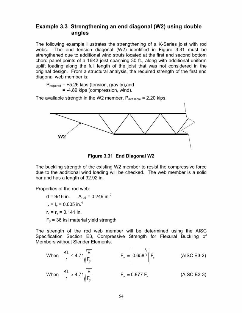
Example 3.3 Strengthening an end diagonal (W2) using double
angles The following example illustrates the strengthening of a K-Series joist with rod webs. The end tension diagonal (W2) identified in Figure 3.31 must be strengthened due to additional wind struts located at the first and second bottom chord panel points of a 16K2 joist spanning 30 ft., along with additional uniform uplift loading along the full length of the joist that was not considered in the original design. From a structural analysis, the required strength of the first end diagonal web member is:
Prequired = +5.26 kips (tension, gravity),and = -4.89 kips (compression, wind).
The available strength in the W2 member, Pavailable = 2.20 kips.
Figure 3.31 End Diagonal W2
The buckling strength of the existing W2 member to resist the compressive force due to the additional wind loading will be checked. The web member is a solid bar and has a length of 32.92 in. Properties of the rod web:
d = 9/16 in. Arod = 0.249 in.2 Ix = Iy = 0.005 in.4 rx = ry = 0.141 in. Fy = 36 ksi material yield strength
The strength of the rod web member will be determined using the AISC Specification Section E3, Compressive Strength for Flexural Buckling of Members without Slender Elements.
When yFF
cry
F658.0FFE71.4
rKL
e
y
⎥⎥⎦
⎤
⎢⎢⎣
⎡=≤ (AISC E3-2)
When ecry
F877.0FFE71.4
rKL
=> (AISC E3-3)
55
68.13336
2900071.448.233r
KL=>=
( )( )
ksi25.548.233
29000F 2
2
e =π
=
( ) ksi60.425.5877.0Fcr ==
ksi76.2FFc
cra =
Ω=
( )( ) requiredkips89.4kips69.0249.076.2Pavailable <== Therefore, NG Reinforcing the first diagonal web member (W2) of the joist is required as it is overstressed. A pair of angles will be chosen for the reinforcement thus allowing the existing member to stay in-place. Since the configuration of the joist has a rod web, the first end diagonal member is installed between the top chord angles. The vertical legs of the seat angles are welded to the outside face of the vertical legs of the top chord angles, not allowing an adequate surface for the attachment of new end diagonals. Therefore, the existing seat angles will need to be removed by ‘washing away’ the weld without damaging the top chord and then grinding smooth the surface of the vertical legs of the top chord. The seat must then be replaced in a different manner as shown below. The reinforcement design will ignore the existing rod web member strength. Reinforcement design – Trial 1
Try: 2L’s 1 ¼ x 1 ¼ x 1/8 in. Properties of one angle are as follows: A = 0.297 in.2 Ix = Iy = 0.044 in.4 rx = ry = 0.385 in. rz = 0.246 in. Fy = 36 ksi material yield strength
Design for the gravity force (tension) Check slenderness of a single angle:
82.133246.092.32
rL
==
The AISC Specifications Chapter D, Section D1 (AISC 2005) no longer has a maximum slenderness requirement though it is still preferred that the slenderness ratio should not exceed 300. Determine Pn for the 2L’s 1 ¼ x 1 ¼ x 1/8 in.
56
For tensile yielding:
( )( )( ) kips38.21297.0362AFP gyn ===
kips80.1267.138.21PP
t
navailable ==
Ω=
For tensile rupture:
eun AFUP =
Worst case scenario U = 0.6 (from AISC Specification Table D3.1)
( )( )( )( ) kips67.20297.0586.02Pn ==
kips34.1000.267.20PP
t
navailable ==
Ω= (controls) > 5.26 kips Therefore, OK
Design for the wind force (compression) Check slenderness of a single angle:
( )( ) 82.133246.0
92.320.1r
KL==
The AISC Specifications Chapter E, Section E2 (AISC 2005) no longer has a maximum slenderness requirement though it is still preferred that the effective slenderness ratio should not exceed 200. The angle reinforcement of the W2 member shall be designed using the AISC Specification Section E5, Single Angle Compression Members.
When xx rL75.072
rKL80
rL0 +=≤≤ (AISC E5-1)
When 200rL25.132
rKL80
rL
xx
≤+=> (AISC E5-2)
L/rx = 32.92/0.385 = 85.51
( ) 88.13851.8525.132rL25.132
rKL
x
=+=+=
The strength of the single angle can now be determined using the AISC Specification Section E3, Compressive Strength for Flexural Buckling of Members without Slender Elements since Qs = 1.0 (from Appendix B).
When yFF
cry
F658.0FFE71.4
rKL
e
y
⎥⎥⎦
⎤
⎢⎢⎣
⎡=≤ (AISC E3-2)
57
When ecry
F877.0FFE71.4
rKL
=> (AISC E3-3)
68.13336
2900071.488.138r
KL=>=
( )( )
ksi84.1488.138
29000F 2
2
e =π
=
( ) ksi01.1384.14877.0Fcr ==
ksi79.7FFc
cra =
Ω=
And, the available force in the two angles is:
( )( )( ) requiredkips89.4kips63.4297.079.72Pavailable <== Therefore, NG Increase the reinforcement angle size to 2L’s 1 ¼ x 1 ¼ x 3/16 in.
Properties of one angle are as follows: A = 0.434 in.2 Ix = Iy = 0.061 in.4 rx = ry = 0.377 in. rz = 0.244 in.
Fy = 36 ksi material yield strength
Design for the gravity force (tension) Determine Pn for the 2L’s 1 ¼ x 1 ¼ x 3/16 in.: For tensile yielding:
( )( )( ) kips25.31434.0362AFP gyn ===
kips71.1867.125.31PP
t
navailable ==
Ω=
For tensile rupture:
eun AFUP =
Worst case scenario U = 0.6 (from AISC Specification Table D3.1)
( )( )( )( ) kips21.30434.0586.02Pn ==
kips10.1500.221.30PP
t
navailable ==
Ω= (controls) > 5.26 kips Therefore, OK
58
Design for the wind force (compression) Check slenderness of a single angle: L/rx = 32.92/0.377 = 87.32
( ) 15.14132.8725.132rL25.132
rKL
x
=+=+=
68.13336
2900071.415.141r
KL=>=
( )( )
ksi37.1415.141
29000F 2
2
e =π
=
( ) ksi60.1237.14877.0Fcr ==
ksi54.7FFc
cra =
Ω=
And, the available force in the two angles is:
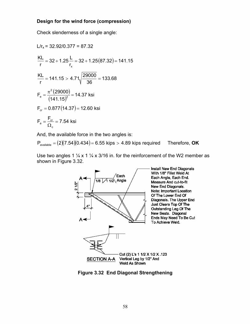
( )( )( ) requiredkips89.4kips55.6434.054.72Pavailable >== Therefore, OK Use two angles 1 ¼ x 1 ¼ x 3/16 in. for the reinforcement of the W2 member as shown in Figure 3.32.
Figure 3.32 End Diagonal Strengthening
59
Weld connection design of reinforcement angles to chord: Use a 1/8 in. fillet weld since the reinforcing angles will be the thinner members to be joined to the chord angles (AISC Specification Table J2.4 Minimum Size of Fillet Welds). The allowable shear per weld using E70 electrodes (FEXX = 70 ksi) is determined from the AISC Specification Table J2.5, Available Strength of Welded Joints as follows:
( )w
EXXew
F60.0tFΩ
= Eq. 3-11
( )( )( )( ) .in/kips856.100.2
7060.0125.0707.0Fw ==
The length of weld required for each angle, each end equals:
( )( ) .in42.1856.1226.5
F2PL
w
rweld === say 1 1/2 in.
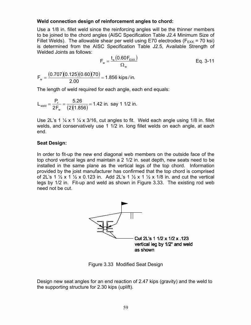
Use 2L’s 1 ¼ x 1 ¼ x 3/16, cut angles to fit. Weld each angle using 1/8 in. fillet welds, and conservatively use 1 1/2 in. long fillet welds on each angle, at each end. Seat Design: In order to fit-up the new end diagonal web members on the outside face of the top chord vertical legs and maintain a 2 1/2 in. seat depth, new seats need to be installed in the same plane as the vertical legs of the top chord. Information provided by the joist manufacturer has confirmed that the top chord is comprised of 2L’s 1 ½ x 1 ½ x 0.123 in. Add 2L’s 1 ½ x 1 ½ x 1/8 in. and cut the vertical legs by 1/2 in. Fit-up and weld as shown in Figure 3.33. The existing rod web need not be cut.
Figure 3.33 Modified Seat Design
Design new seat angles for an end reaction of 2.47 kips (gravity) and the weld to the supporting structure for 2.30 kips (uplift).
60
Seat Angle Properties: Consider only the combined section of the vertical leg of the top chord angles and the vertical leg of the seat angles (see Figure 3.34) to resist the axial load.
Figure 3.34 Column Section for Seat Design
( )( ) 2seat .in0.14125.02A ==
( )( ) 433
x .in33.112
4125.0212bh2I ===
( )( ) ( )( ) 423
2seat
3
y .in238.034375.00.1212
125.042dA212hb2I =+=+=
.in15.10.133.1
AIrseat
xx ===
.in488.00.1
238.0A
Ir
seat
yy ===
When yFF
cry
F658.0FFE71.4
rKL
e
y
⎥⎥⎦
⎤
⎢⎢⎣
⎡=≤ (AISC E3-2)
When ecry
F877.0FFE71.4
rKL
=> (AISC E3-3)
61
68.13336
2900071.4123.5r
KL=<=
( )( )
ksi10905123.529000F 2
2
e =π
=
ksi95.3536658.0F 1090536
cr =⎥⎦
⎤⎢⎣
⎡=
ksi53.21FFc
cra =
Ω=
And, the available force is:
( )( ) requiredkips47.2kips53.210.153.21Pavailable >== Therefore, OK Use 2L’s 1 ½ x 1 ½ x 0.125 x 4 in. long for the new seat. Cut each vertical leg by ½ in. and weld to the existing vertical leg of the top chord. Align the vertical legs such that they are in the same plane. Weld using a square groove (partial-joint-penetration groove) weld. The seat angle weld to the supporting structure needs to be capable of resisting a load of 2.30 kips. Use a 1/8 in. fillet weld since the seat angles will be the thinner members to be joined. The allowable shear per weld using E70 electrodes (FEXX = 70 ksi) is
.in/kips856.1Fw =
The length of weld required for each seat angle is:
( )( ) .in620.0856.1230.2
F2PL
w
rweld ===
Use a 1/8 in. fillet weld with a minimum weld length of 1 in. on each seat angle.
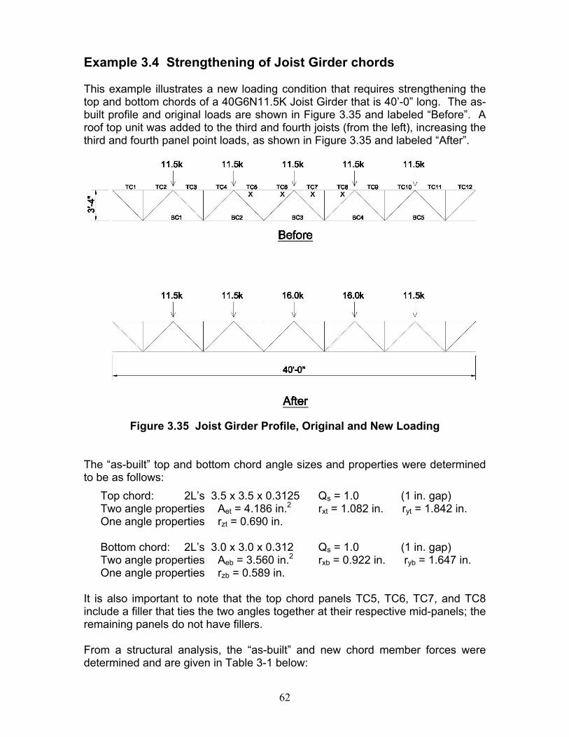
62
Example 3.4 Strengthening of Joist Girder chords This example illustrates a new loading condition that requires strengthening the top and bottom chords of a 40G6N11.5K Joist Girder that is 40’-0” long. The as-built profile and original loads are shown in Figure 3.35 and labeled “Before”. A roof top unit was added to the third and fourth joists (from the left), increasing the third and fourth panel point loads, as shown in Figure 3.35 and labeled “After”.
Figure 3.35 Joist Girder Profile, Original and New Loading
The “as-built” top and bottom chord angle sizes and properties were determined to be as follows: Top chord: 2L’s 3.5 x 3.5 x 0.3125 Qs = 1.0 (1 in. gap) Two angle properties Aet = 4.186 in.2 rxt = 1.082 in. ryt = 1.842 in. One angle properties rzt = 0.690 in. Bottom chord: 2L’s 3.0 x 3.0 x 0.312 Qs = 1.0 (1 in. gap) Two angle properties Aeb = 3.560 in.2 rxb = 0.922 in. ryb = 1.647 in. One angle properties rzb = 0.589 in. It is also important to note that the top chord panels TC5, TC6, TC7, and TC8 include a filler that ties the two angles together at their respective mid-panels; the remaining panels do not have fillers. From a structural analysis, the “as-built” and new chord member forces were determined and are given in Table 3-1 below:
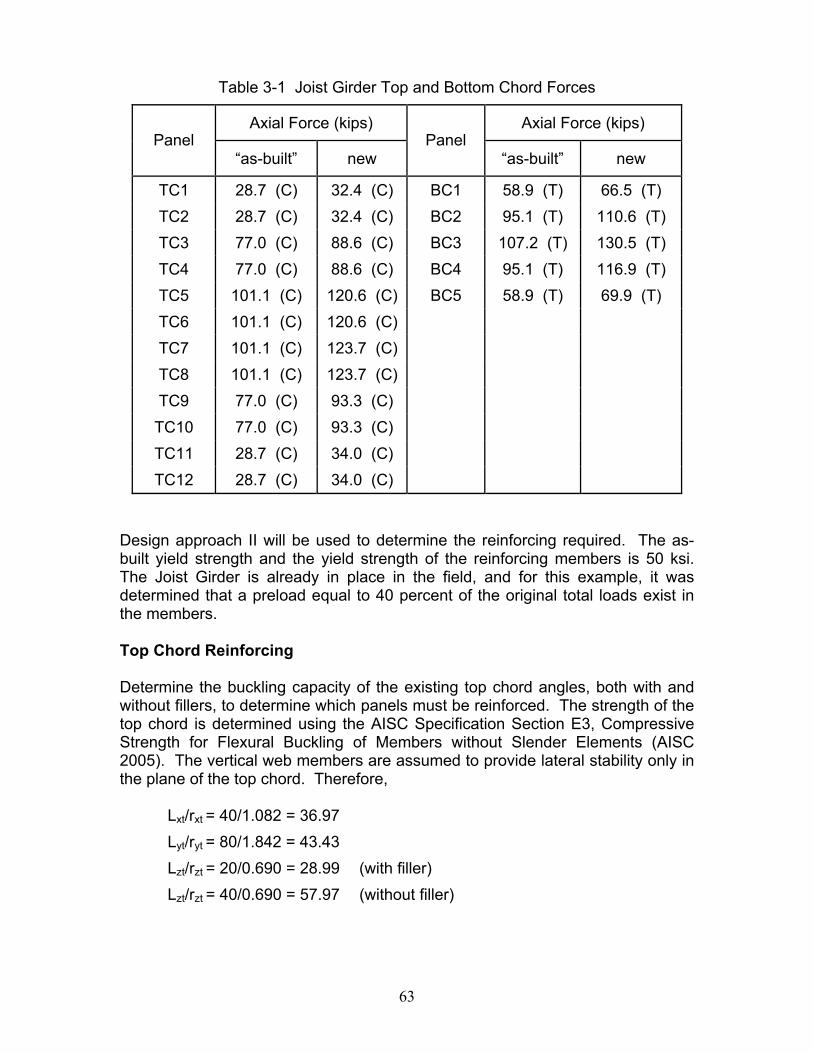
63
Table 3-1 Joist Girder Top and Bottom Chord Forces
Axial Force (kips) Axial Force (kips) Panel
“as-built” new Panel
“as-built” new
TC1 28.7 (C) 32.4 (C) BC1 58.9 (T) 66.5 (T) TC2 28.7 (C) 32.4 (C) BC2 95.1 (T) 110.6 (T) TC3 77.0 (C) 88.6 (C) BC3 107.2 (T) 130.5 (T) TC4 77.0 (C) 88.6 (C) BC4 95.1 (T) 116.9 (T) TC5 101.1 (C) 120.6 (C) BC5 58.9 (T) 69.9 (T) TC6 101.1 (C) 120.6 (C) TC7 101.1 (C) 123.7 (C) TC8 101.1 (C) 123.7 (C) TC9 77.0 (C) 93.3 (C) TC10 77.0 (C) 93.3 (C) TC11 28.7 (C) 34.0 (C) TC12 28.7 (C) 34.0 (C)
Design approach II will be used to determine the reinforcing required. The as-built yield strength and the yield strength of the reinforcing members is 50 ksi. The Joist Girder is already in place in the field, and for this example, it was determined that a preload equal to 40 percent of the original total loads exist in the members. Top Chord Reinforcing Determine the buckling capacity of the existing top chord angles, both with and without fillers, to determine which panels must be reinforced. The strength of the top chord is determined using the AISC Specification Section E3, Compressive Strength for Flexural Buckling of Members without Slender Elements (AISC 2005). The vertical web members are assumed to provide lateral stability only in the plane of the top chord. Therefore,
Lxt/rxt = 40/1.082 = 36.97 Lyt/ryt = 80/1.842 = 43.43 Lzt/rzt = 20/0.690 = 28.99 (with filler) Lzt/rzt = 40/0.690 = 57.97 (without filler)
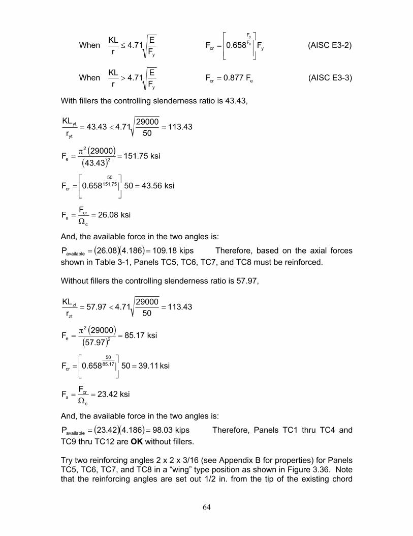
64
When yFF
cry
F658.0FFE71.4
rKL
e
y
⎥⎥⎦
⎤
⎢⎢⎣
⎡=≤ (AISC E3-2)
When ecry
F877.0FFE71.4
rKL
=> (AISC E3-3)
With fillers the controlling slenderness ratio is 43.43,
43.11350
2900071.443.43r
KL
yt
yt =<=
( )( )
ksi75.15143.43
29000F 2
2
e =π
=
ksi56.4350658.0F 75.15150
cr =⎥⎦
⎤⎢⎣
⎡=
ksi08.26FFc
cra =
Ω=
And, the available force in the two angles is:
( )( ) kips18.109186.408.26Pavailable == Therefore, based on the axial forces shown in Table 3-1, Panels TC5, TC6, TC7, and TC8 must be reinforced. Without fillers the controlling slenderness ratio is 57.97,
43.11350
2900071.497.57r
KLzt
zt =<=
( )( )
ksi17.8597.57
29000F 2
2
e =π
=
ksi11.3950658.0F 17.8550
cr =⎥⎦
⎤⎢⎣
⎡=
ksi42.23FFc
cra =
Ω=
And, the available force in the two angles is:
( )( ) kips03.98186.442.23Pavailable == Therefore, Panels TC1 thru TC4 and TC9 thru TC12 are OK without fillers. Try two reinforcing angles 2 x 2 x 3/16 (see Appendix B for properties) for Panels TC5, TC6, TC7, and TC8 in a “wing” type position as shown in Figure 3.36. Note that the reinforcing angles are set out 1/2 in. from the tip of the existing chord
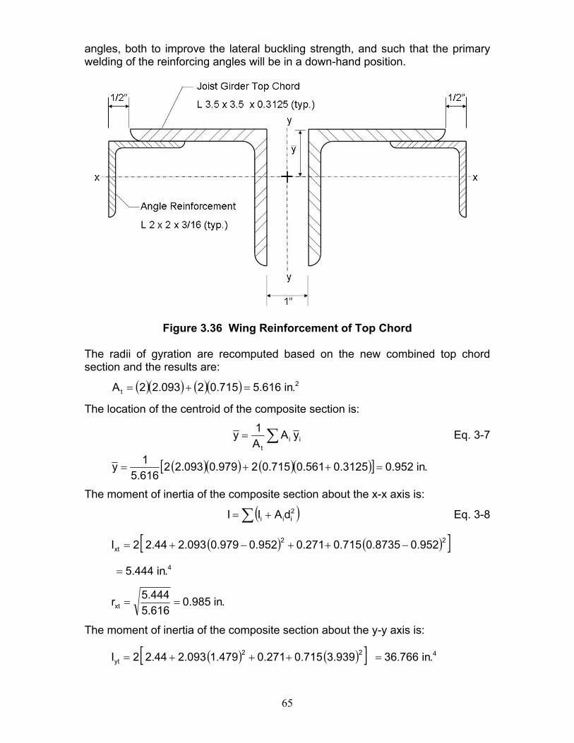
65
angles, both to improve the lateral buckling strength, and such that the primary welding of the reinforcing angles will be in a down-hand position.
Figure 3.36 Wing Reinforcement of Top Chord
The radii of gyration are recomputed based on the new combined top chord section and the results are:
( )( ) ( )( ) 2t .in616.5715.02093.22A =+=
The location of the centroid of the composite section is:
∑= iit
yAA1y Eq. 3-7
( )( ) ( )( )[ ] .in952.03125.0561.0715.02979.0093.22616.51y =++=
The moment of inertia of the composite section about the x-x axis is:
( )∑ += 2iii dAII Eq. 3-8
( ) ( )[ ]4
22xt
.in444.5
952.08735.0715.0271.0952.0979.0093.244.22I
=
−++−+=
.in985.0616.5444.5rxt ==
The moment of inertia of the composite section about the y-y axis is:
( ) ( )[ ] 422yt .in766.36939.3715.0271.0479.1093.244.22I =+++=
66
.in559.2616.5766.36ryt ==
Lxt/rxt = 40/0.985 = 40.61 (controls) Lyt/ryt = 80/2.559 = 31.26
Determine the yield stress to be used for the reinforcement design:
Preload, Pp = (0.40)(101.1) = 40.44 kips
( )( ) ksi66.9093.2244.40fp ==
Yield stress to be used is the minimum of:
Fye – fp = 50 – 9.66 = 40.34 ksi, and Fy = 50 ksi for the angles
Thus, use 40.34 ksi.
Using this yield stress in the same equations as before, the available compressive axial stress equals
29.12634.40
2900071.461.40r
KLxt
xt =<=
( )( )
ksi55.17361.40
29000F 2
2
e =π
=
ksi60.3634.40658.0F 55.17334.40
cr =⎥⎦
⎤⎢⎣
⎡=
ksi92.21FFc
cra =
Ω=
And, the available force in the reinforced top chord using two angles is:
( )( ) kips7.123kips08.123616.592.21Pavailable ≈== Therefore, OK Design the welds for the force in the reinforcing members. The total force in the welds determined by Equation 3-5 is:
( ) kips20.2144.407.123616.543.1Prw =−⎟
⎠⎞
⎜⎝⎛=
Use 3/16 in. fillet welds. The allowable shear per weld using E70 electrodes (FEXX = 70 ksi) is determined from the AISC Specification Table J2.5, Available Strength of Welded Joints as follows:
67
( )w
EXXew
F60.0tFΩ
= Eq. 3-11
( )( )( ) .in/kips78.200.2
7060.01875.0707.0Fw ==
The total length of weld required to develop the force in each angle equals ( )( )[ ] .in81.378.2220.21 =
The 6 in. of weld shown in Figure 3.38 Section A-A is more than adequate and is applied at the heel of the reinforcing angle. Only a nominal additional weld is applied at the toe of the reinforcing angle. The 2 in. of weld at the panel points is adequate to develop the change in force from panel to panel and the same weld is used at the third points of each panel. Thus, the slenderness ratio for one reinforcing angle is:
61.4084.33394.0
340rL
zt
z <=⎟⎠⎞
⎜⎝⎛= Therefore, does not control.
Bottom Chord Reinforcing:
Total area required = ( )( ) be
po
pttr A
PPPP
A−−
=
where:
Pt = 130.5 kips Pp = 0.40 (107.2) = 42.9 kips Po = 107.2 kips
Aeb = 3.560 in.2 (area of original two 3.0 x 3.0 x 0.312 angles)
Thus,
( )( ) ( ) 2
tr .in850.4560.39.422.1079.425.130A =
−−
=
The required area of reinforcing equals 2
etrr .in290.1560.3850.4AAA =−=−=
Try two angles 2 x 2 x 3/16 (see Appendix B for properties). Place the angles in a “wing” type position as shown in Figure 3.37, inset from the tip of the existing bottom chord angles so as to facilitate a down-hand welding position.
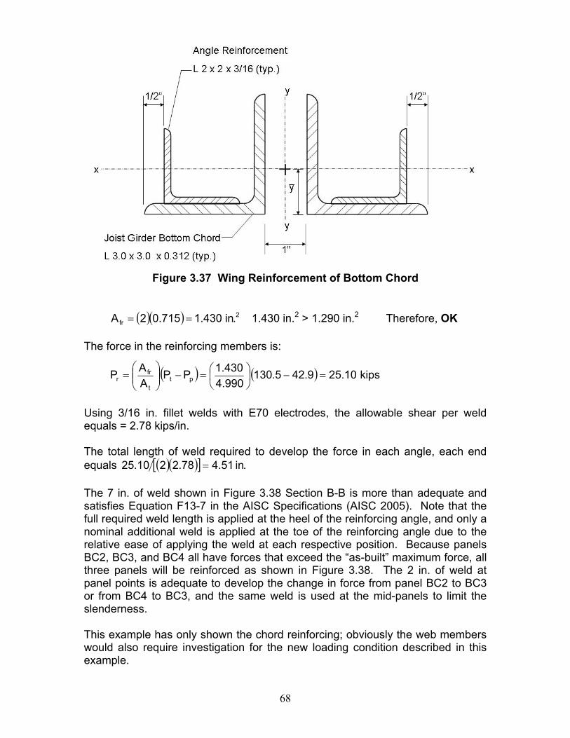
68
Figure 3.37 Wing Reinforcement of Bottom Chord
( )( ) 2fr .in430.1715.02A == 1.430 in.2 > 1.290 in.2 Therefore, OK
The force in the reinforcing members is:
( ) ( ) kips10.259.425.130990.4430.1PP
AAP pt
t
frr =−⎟
⎠⎞
⎜⎝⎛=−⎟⎟
⎠
⎞⎜⎜⎝
⎛=
Using 3/16 in. fillet welds with E70 electrodes, the allowable shear per weld equals = 2.78 kips/in. The total length of weld required to develop the force in each angle, each end equals ( )( )[ ] .in51.478.2210.25 = The 7 in. of weld shown in Figure 3.38 Section B-B is more than adequate and satisfies Equation F13-7 in the AISC Specifications (AISC 2005). Note that the full required weld length is applied at the heel of the reinforcing angle, and only a nominal additional weld is applied at the toe of the reinforcing angle due to the relative ease of applying the weld at each respective position. Because panels BC2, BC3, and BC4 all have forces that exceed the “as-built” maximum force, all three panels will be reinforced as shown in Figure 3.38. The 2 in. of weld at panel points is adequate to develop the change in force from panel BC2 to BC3 or from BC4 to BC3, and the same weld is used at the mid-panels to limit the slenderness. This example has only shown the chord reinforcing; obviously the web members would also require investigation for the new loading condition described in this example.
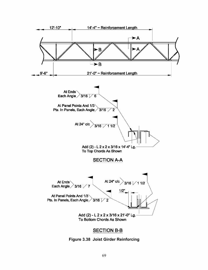
69
Figure 3.38 Joist Girder Reinforcing
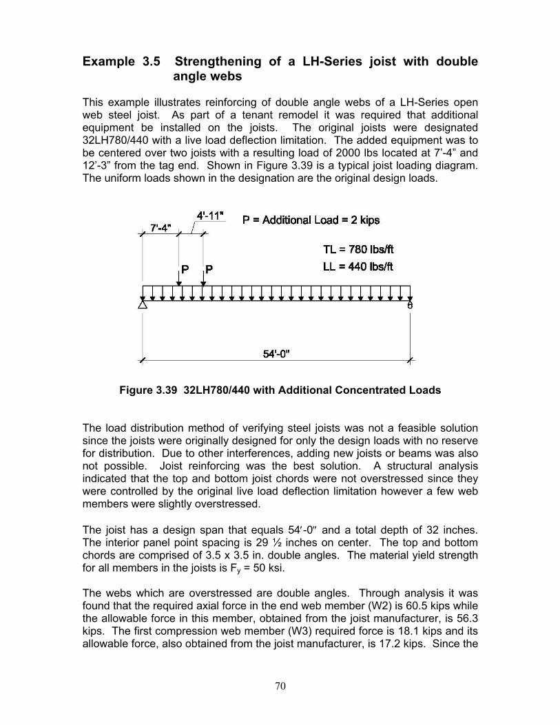
70
Example 3.5 Strengthening of a LH-Series joist with double
angle webs This example illustrates reinforcing of double angle webs of a LH-Series open web steel joist. As part of a tenant remodel it was required that additional equipment be installed on the joists. The original joists were designated 32LH780/440 with a live load deflection limitation. The added equipment was to be centered over two joists with a resulting load of 2000 lbs located at 7’-4” and 12’-3” from the tag end. Shown in Figure 3.39 is a typical joist loading diagram. The uniform loads shown in the designation are the original design loads.
Figure 3.39 32LH780/440 with Additional Concentrated Loads
The load distribution method of verifying steel joists was not a feasible solution since the joists were originally designed for only the design loads with no reserve for distribution. Due to other interferences, adding new joists or beams was also not possible. Joist reinforcing was the best solution. A structural analysis indicated that the top and bottom joist chords were not overstressed since they were controlled by the original live load deflection limitation however a few web members were slightly overstressed. The joist has a design span that equals 54′-0″ and a total depth of 32 inches. The interior panel point spacing is 29 ½ inches on center. The top and bottom chords are comprised of 3.5 x 3.5 in. double angles. The material yield strength for all members in the joists is Fy = 50 ksi. The webs which are overstressed are double angles. Through analysis it was found that the required axial force in the end web member (W2) is 60.5 kips while the allowable force in this member, obtained from the joist manufacturer, is 56.3 kips. The first compression web member (W3) required force is 18.1 kips and its allowable force, also obtained from the joist manufacturer, is 17.2 kips. Since the
71
joists were originally designed using Allowable Stress Design method (ASD), those same procedures are used to determine the required reinforcement. Approach II will be used in this example. End Web Reinforcing: The load in the end tension web (W2) at the time of reinforcing is 23.0 kips.
Total area required = ( )( ) e
po
pttr A
PPPP
A−−
=
where:
Pt = 60.5 kips (required force) Pp = 23.0 kips (preload force) Po = 56.3 kips (original allowable design force)
Ae = 1.876 in.2 (area of original two 2.0 x 2.0 x 0.250 angles)
Thus,
( )( ) ( ) 2
tr .in113.2876.10.233.560.235.60A =
−−
=
The required area of reinforcing equals 2
etrr .in237.0876.1113.2AAA =−=−=
Adding round rods work well for double angle reinforcement so use 2 - 3/4” diameter rods placed in the heel of the angles. Area of furnished reinforcing,
( ) 222
fr .in884.0475.02
4d2A =
π=
π= > 0.237 in.2 Therefore, OK
The total area, At, is the sum of the areas of the existing web angles plus the areas of the reinforcing rods,
2fret .in760.2884.0876.1AAA =+=+=
The force in the reinforcing member equals:
( ) ( ) kips01.120.235.60760.2884.0PP
AAP pt
t
frr =−⎟
⎠⎞
⎜⎝⎛=−⎟⎟
⎠
⎞⎜⎜⎝
⎛=
Check the stress in the round rod reinforcing member: F = P/A =12.01/0.884 = 13.59 ksi < 21.6 ksi
Therefore, the use of A36 material is OK.
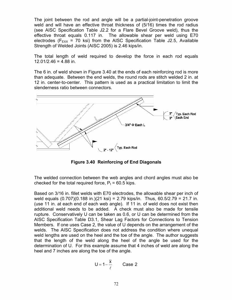
72
The joint between the rod and angle will be a partial-joint-penetration groove weld and will have an effective throat thickness of (5/16) times the rod radius (see AISC Specification Table J2.2 for a Flare Bevel Groove weld), thus the effective throat equals 0.117 in. The allowable shear per weld using E70 electrodes (FEXX = 70 ksi) from the AISC Specification Table J2.5, Available Strength of Welded Joints (AISC 2005) is 2.46 kips/in. The total length of weld required to develop the force in each rod equals 12.01/2.46 = 4.88 in. The 6 in. of weld shown in Figure 3.40 at the ends of each reinforcing rod is more than adequate. Between the end welds, the round rods are stitch welded 2 in. at 12 in. center-to-center. This pattern is used as a practical limitation to limit the slenderness ratio between connectors.
Figure 3.40 Reinforcing of End Diagonals
The welded connection between the web angles and chord angles must also be checked for the total required force, Pt = 60.5 kips. Based on 3/16 in. fillet welds with E70 electrodes, the allowable shear per inch of weld equals (0.707)(0.188 in.)(21 ksi) = 2.79 kips/in. Thus, 60.5/2.79 = 21.7 in. (use 11 in. at each end of each web angle). If 11 in. of weld does not exist then additional weld needs to be added. A check must also be made for tensile rupture. Conservatively U can be taken as 0.6, or U can be determined from the AISC Specification Table D3.1, Shear Lag Factors for Connections to Tension Members. If one uses Case 2, the value of U depends on the arrangement of the welds. The AISC Specification does not address the condition where unequal weld lengths are used on the heel and the toe of the angle. The author suggests that the length of the weld along the heel of the angle be used for the determination of U. For this example assume that 4 inches of weld are along the heel and 7 inches are along the toe of the angle.
2Casex1Ul
−=
73
where: x is the centroid location for the composite section comprised of web angle plus the round rod and l is the length of the connection.
The nominal strength Pn based on tensile rupture equals FuAe or UFuAt Since the weld is placed on the angle in the connection to the chords Fu can be taken as 65 ksi and x can conservatively be taken at the centroid location of the round rod, thus x equals (0.25 + 0.375) = 0.625 in.
844.04625.01U =−=
( )( )( ) kips4.151760.265844.0AFUP tun ===
kips71.7500.2
4.151PPt
navailable ==
Ω= > 60.5 kips Therefore, OK
First Compression Web Reinforcing The load in the first compression web (W3) at the time of reinforcing is 6.9 kips. Design Approach: 1. Select a trial reinforcing member. 2. Determine the composite section properties of the reinforcing member and
the existing member. 3. Check the buckling strength of the composite web section. First determine
the magnitude of the compressive stress in the existing member due to the preload, fp. For the buckling check, use Fy as the minimum of (Fye – fp), and Fy of the reinforcing member.
4. Design the weld size and length for the reinforcing member. The force in
the weld is:
( )ptt
frrw PP
AAP −⎟⎟
⎠
⎞⎜⎜⎝
⎛= Eq. 3-5
5. Check buckling of the reinforcing member. Solution: 1. Trial reinforcing member: Try using two 3/4 in. diameter rods, Fy = 36 ksi 2. Determine the composite properties of the combined section shown in
Section A-A of Figure 3.41.
The total area, A, is the sum of the areas of the existing web angles plus the areas of the reinforcing rods,
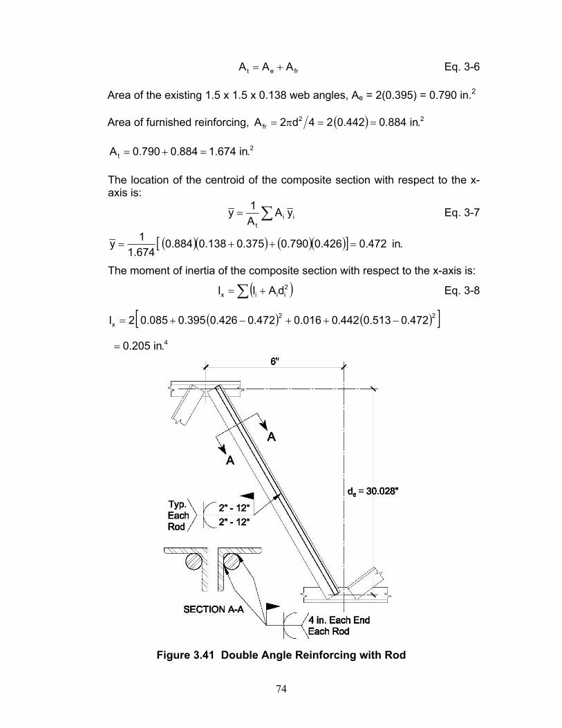
74
fret AAA += Eq. 3-6
Area of the existing 1.5 x 1.5 x 0.138 web angles, Ae = 2(0.395) = 0.790 in.2
Area of furnished reinforcing, ( ) 22fr .in884.0442.024d2A ==π=
2
t .in674.1884.0790.0A =+=
The location of the centroid of the composite section with respect to the x-axis is:
∑= iit
yAA1y Eq. 3-7
( )( ) ( )( )[ ] .in472.0426.0790.0375.0138.0884.0674.11y =++=
The moment of inertia of the composite section with respect to the x-axis is:
( )∑ += 2iiix dAII Eq. 3-8
( ) ( )[ ]4
22x
.in205.0
472.0513.0442.0016.0472.0426.0395.0085.02I
=
−++−+=
Figure 3.41 Double Angle Reinforcing with Rod
75
The radius of gyration of the composite section with respect to the x-axis is:
t
xx A
Ir = Eq. 3-9
.in350.0674.1205.0rx ==
3. Check the buckling strength of the composite web section:
For the compression webs, the allowable load is determined using the AISC Specification Chapter E (AISC 2005). Fillers are used between the two angles thus the provisions for single angles are not required.
tac AFP = Eq. 3-10
where:
Pc is the allowable compressive strength, cnP Ω , kips Fa is the allowable compressive stress, ccrF Ω , ksi At is the composite member cross-sectional area, in.2 Safety factor, 67.1c =Ω
Determine the yield stress to be used for the reinforcement design: Preload, Pp = 6.9 kips
( )( ) ksi73.8395.029.6fp ==
Yield stress to be used is the minimum of:
Fye – fp = 50 – 8.73 = 41.27 ksi, and Fy = 36 ksi for the rods.
Thus, use 36 ksi.
When 0.1QFE45.0
tb
sy
=≤ (AISC E7-10)
0.1Q77.1236
2900045.0FE45.087.10
138.05.1
sy
===≤=
When yFF
cry
F658.0FFE71.4
rKL
e
y
⎥⎥⎦
⎤
⎢⎢⎣
⎡=≤ (AISC E3-2)
76
When ecry
F877.0FFE71.4
rKL
=> (AISC E3-3)
2
2
e
rKL
EF
⎟⎠⎞
⎜⎝⎛
π= (AISC E3-4)
Compute the slenderness ratio of the composite section. Use an unsupported length based on the effective depth of the joist, where the joist chords are 3.5 x 3.5 in. angles and the horizontal panel length as shown in Figure 3.41. Use an effective length factor K = 1.0.
( ) ( ) .in62.30028.306L 22 =+=
68.13336
2900071.449.87350.062.30
rL
=<==
( ) ksi39.37
350.062.30
29000F 2
2
e =
⎟⎠⎞
⎜⎝⎛
π=
ksi06.2436658.0F 39.3736
cr =⎥⎦
⎤⎢⎣
⎡=
The available axial compressive stress is:
ksi41.14FFc
cra =
Ω=
And, the available compressive force is:
( )( ) requiredkips1.18kips12.24674.141.14Pc >== Therefore, OK
4. Design the welds: The total force in the welds determined by Equation 3-5 is:
( ) kips91.59.61.18674.1884.0Prw =−⎟
⎠⎞
⎜⎝⎛=
Alternately, each of the 3/4 in. diameter rods has an allowable force of (14.41)(0.442) = 6.37 kips. This force will be used for the weld design.
The joint between the rod and angle will be a partial-joint-penetration groove weld and will have an effective throat thickness of (5/16) times the rod radius (see AISC Specification Table J2.2 for a Flare Bevel Groove weld), thus the effective throat equals 0.117 in. The allowable shear per weld using E70 electrodes (FEXX = 70 ksi) from the AISC Specification Table J2.5, Available Strength of Welded Joints (AISC 2005) is 2.46 kips/in.
77
The total length of weld required to develop the force in each rod equals 6.37/2.46 = 2.59 in.
The 4 in. of weld shown in Figure 3.41 at the ends of each reinforcing rod is more than adequate. Between the end welds, the round rods are stitch welded 2 in. at 12 in. center-to-center. This pattern is used as a practical limitation to limit the slenderness ratio between connectors.
5. Check buckling of the reinforcing:
Check buckling of the 3/4 in. diameter reinforcing rod between welds. L = weld spacing – weld length = 12 – 2 = 10 in.
187.0442.0
0155.0AIr ===
Slenderness ratio of the rod is:
4.53187.010
rL
==
( ) ksi09.100
187.01029000F 2
2
e =
⎟⎠⎞
⎜⎝⎛
π=
ksi97.3036658.0F 09.10036
cr =⎥⎦
⎤⎢⎣
⎡=
ksi54.1867.197.30FF
c
cra ==
Ω=
And, the available compressive force is:
( )( ) requiredkips1.18kips04.31674.154.18Pc >== Therefore, OK
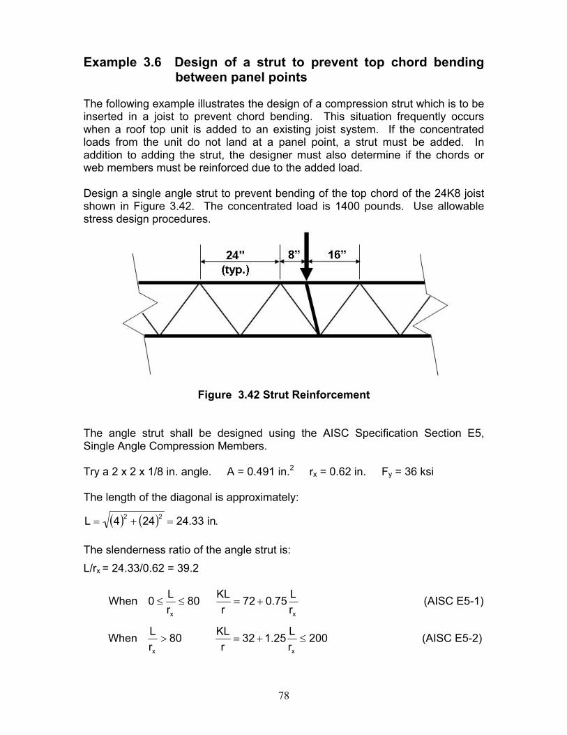
78
Example 3.6 Design of a strut to prevent top chord bending
between panel points The following example illustrates the design of a compression strut which is to be inserted in a joist to prevent chord bending. This situation frequently occurs when a roof top unit is added to an existing joist system. If the concentrated loads from the unit do not land at a panel point, a strut must be added. In addition to adding the strut, the designer must also determine if the chords or web members must be reinforced due to the added load. Design a single angle strut to prevent bending of the top chord of the 24K8 joist shown in Figure 3.42. The concentrated load is 1400 pounds. Use allowable stress design procedures.
Figure 3.42 Strut Reinforcement
The angle strut shall be designed using the AISC Specification Section E5, Single Angle Compression Members. Try a 2 x 2 x 1/8 in. angle. A = 0.491 in.2 rx = 0.62 in. Fy = 36 ksi The length of the diagonal is approximately:
( ) ( ) .in33.24244L 22 =+= The slenderness ratio of the angle strut is: L/rx = 24.33/0.62 = 39.2
When xx rL75.072
rKL80
rL0 +=≤≤ (AISC E5-1)
When 200rL25.132
rKL80
rL
xx
≤+=> (AISC E5-2)
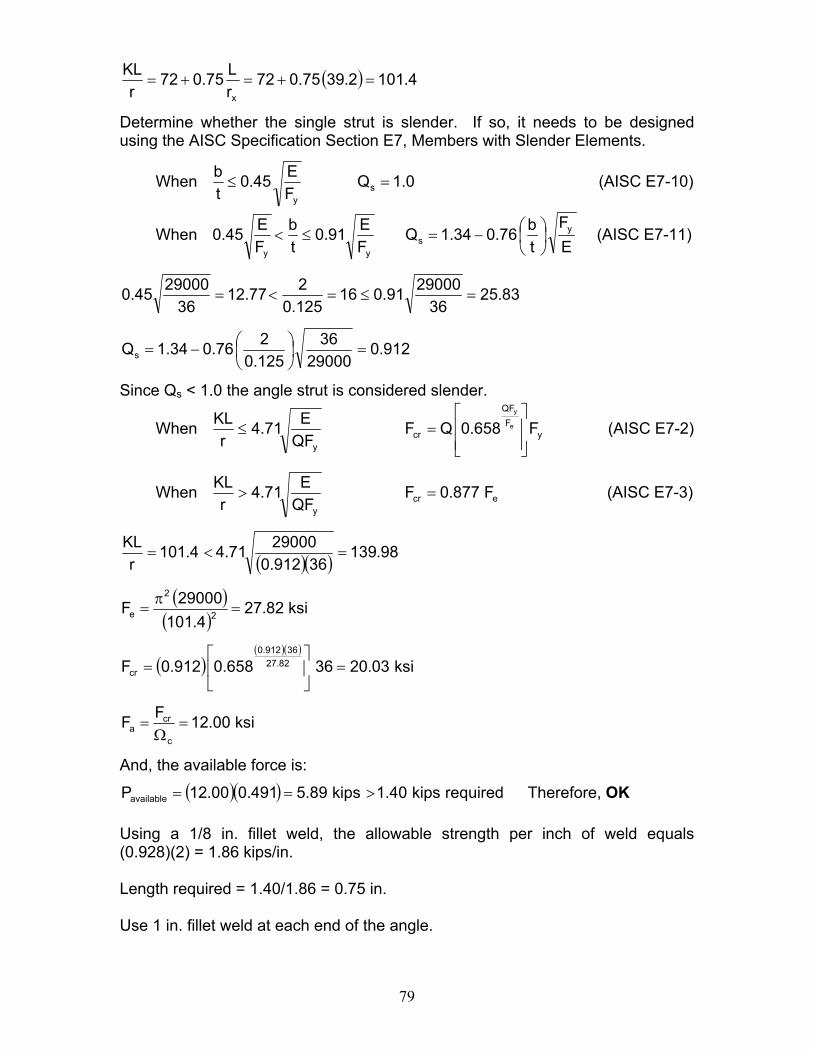
79
( ) 4.1012.3975.072rL75.072
rKL
x
=+=+=
Determine whether the single strut is slender. If so, it needs to be designed using the AISC Specification Section E7, Members with Slender Elements.
When 0.1QFE45.0
tb
sy
=≤ (AISC E7-10)
When EF
tb76.034.1Q
FE91.0
tb
FE45.0 y
syy
⎟⎠⎞
⎜⎝⎛−=≤< (AISC E7-11)
83.2536
2900091.016125.0277.12
362900045.0 =≤=<=
912.029000
36125.0276.034.1Qs =⎟
⎠⎞
⎜⎝⎛−=
Since Qs < 1.0 the angle strut is considered slender.
When yF
QF
cry
F658.0QFQFE71.4
rKL
e
y
⎥⎥⎦
⎤
⎢⎢⎣
⎡=≤ (AISC E7-2)
When ecry
F877.0FQFE71.4
rKL
=> (AISC E7-3)
( )( ) 98.13936912.0
2900071.44.101r
KL=<=
( )( )
ksi82.274.101
29000F 2
2
e =π
=
( )( )( )
ksi03.2036658.0912.0F 82.2736912.0
cr =⎥⎦
⎤⎢⎣
⎡=
ksi00.12FFc
cra =
Ω=
And, the available force is:
( )( ) requiredkips40.1kips89.5491.000.12Pavailable >== Therefore, OK Using a 1/8 in. fillet weld, the allowable strength per inch of weld equals (0.928)(2) = 1.86 kips/in. Length required = 1.40/1.86 = 0.75 in. Use 1 in. fillet weld at each end of the angle.
80
CHAPTER 4
DESIGN APPROACHES FOR MODIFYING JOISTS- SHORTENING AND LENGTHENING
On occasion joists must be either lengthened or shortened in the field. The designer should be aware that even a small length increase can cause a considerable increase in chord forces. In addition, whether lengthening or shortening is required, web stress reversal may occur and all web members must be checked. The designer must also be aware that the joist camber may be adversely affected when lengthening or shortening a joist. Removal of any main diagonal web member may cause the joist to lose some camber. Steps should be taken during the modification to maintain the original camber. If several joists require modification the designer should first estimate whether it is less expensive to obtain new joists or to use new beams in place of the joists. It may be less expensive to buy even a single joist considering both material and labor costs. It would depend on the length of the joist. Small joists are fairly inexpensive; shipping may be the greatest expense. Time of delivery often affects this decision as much as cost; however the time it takes to design the reinforcing, purchase and deliver the reinforcing materials, and the time to repair the joist may be just as long as new joist delivery. Shortening a joist may not require the addition of reinforcing on the chords or webs, but may require the design of splices for the chords and webs. Shortening joists may require new bearing seats and also new end webs. A common, but unacceptable, practice is to cut off the end of the joist top chord and bearing seat and bend the existing end web and weld it to the top chord. Lengthening a joist generally requires the addition of reinforcing of the chord and some of the web members. The location along the length of the joist as to where the splice is to be made is critical. Typically, splices are made either at the joist center, which reduces the web splice requirement, or at the joist end panel, which reduces the chord splice requirement. The designer should also determine if it is possible to relocate or change the support for the joists so that joist modification is not necessary. Design steps for shortening and lengthening of open web steel joists are shown below.
81
Steps to Shorten Open Web Steel Joists 1. Determine the original web layout (specifically top chord end panel length,
interior panel length, and number of panels) and material sizes. 2. Determine where the shortened length occurs relative to top chord panels.
The new end web is to originate from a bottom chord panel point and should have a placement angle from vertical in an approximate range of 45 to 70 degrees. Depending on the new length, it may be required to remove interior panels.
3. Determine the loading at shortened length. For a standard SJI joist designation, use the SJI Load Table load-carrying capacity for the new length. For special uniform loads, the loading should remain the same. Determine if any partial uniform or concentrated loads remain on the joists at the shortened length and use accordingly.
4. Perform a design at the new length with the appropriate loading and compare the material required for the new length to material for the as-built length. The most likely change is increased web size near the shortened end due to the change in shear. Reinforce undersized existing webs as needed.
5. Place the new bearing seat at the desired location at the end of the joist. This would typically be a pair of angles welded between the top chord angles.
6. Determine the new end web force. Typically, a replacement end web is comprised of two round bars or two new angles. When joists have 2 ½ in. deep bearing seats, it may be difficult to find a shape other than a round that will fit dimensionally with adequate material and available weld strength. The new round bars are placed on the outside of the chords and extend from end bottom chord panel point to inside of the bearing seat at the top chord. The round bars are initially sized to satisfy stress and slenderness ratio requirements. Determine the available weld length on the chords and compare it to the weld length required for the end web force. Use AWS guidelines for a flare-bevel weld throat of 5R/16. Increase the bar diameter if needed to achieve sufficient weld throat.
82
Steps to Lengthen Open Web Steel Joists 1. Determine the original web layout (specifically top chord end panel length,
interior panel length, and number of panels) and material sizes. 2. Typically, adding panels to lengthen joists in the field is not considered. As
a result, there is a limit to how much length can be added based on the slenderness ratio of the new end web and possible governing of the top chord size in a lengthened end panel. Therefore, it is usually advisable to allow the existing end web to remain in order to limit the length of the end panel.
3. Determine the loading at increased length. For a standard SJI joist designation, use the SJI Load Table load-carrying capacity for the new length. For special uniform loads, the loading should remain the same. Determine if any partial uniform or concentrated loads remain or are added to the joists at the new length and use accordingly.
4. Perform a design at the new length with the appropriate loading and compare the material required for the new length to material for the as-built length. Reinforce chords and webs as needed.
5. Place and weld new top chord angles at the end of the existing angles using either a pre-qualified butt weld procedure per AWS Specifications or splice with new material and weld using a weld that has been sized to develop adequate strength.
6. Place the new bearing seat at the desired location at the end of the joist. This would typically be a pair of angles welded between the top chord angles.
7. Determine the new end web force. Typically, a replacement end web is comprised of two round bars. They are placed on the outside of the chords and extend from the end bottom chord panel point to the inside of the bearing seat at the top chord. It may be necessary to remove the horizontal portion of the existing bearing seat to allow passage of the new end web. The round bars are initially sized to satisfy stress and slenderness ratio requirements. Determine the available weld length on the chords and compare it to the weld length required for the end web force. Use AWS guidelines for a flare-bevel weld throat of 5R/16. Increase the bar diameter if needed to achieve sufficient weld throat.
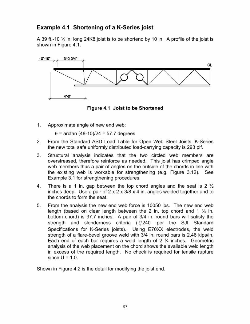
83
Example 4.1 Shortening of a K-Series joist A 39 ft.-10 ½ in. long 24K8 joist is to be shortend by 10 in. A profile of the joist is shown in Figure 4.1.
Figure 4.1 Joist to be Shortened
1. Approximate angle of new end web:
θ = arctan (48-10)/24 = 57.7 degrees 2. From the Standard ASD Load Table for Open Web Steel Joists, K-Series
the new total safe uniformly distributed load-carrying capacity is 293 plf. 3. Structural analysis indicates that the two circled web members are
overstressed, therefore reinforce as needed. This joist has crimped angle web members thus a pair of angles on the outside of the chords in line with the existing web is workable for strengthening (e.g. Figure 3.12). See Example 3.1 for strengthening procedures.
4. There is a 1 in. gap between the top chord angles and the seat is 2 ½ inches deep. Use a pair of 2 x 2 x 3/8 x 4 in. angles welded together and to the chords to form the seat.
5. From the analysis the new end web force is 10050 lbs. The new end web length (based on clear length between the 2 in. top chord and 1 ¾ in. bottom chord) is 37.7 inches. A pair of 3/4 in. round bars will satisfy the strength and slenderness criteria ( 240l per the SJI Standard Specifications for K-Series joists). Using E70XX electrodes, the weld strength of a flare-bevel groove weld with 3/4 in. round bars is 2.46 kips/in. Each end of each bar requires a weld length of 2 ¼ inches. Geometric analysis of the web placement on the chord shows the available weld length in excess of the required length. No check is required for tensile rupture since U = 1.0.
Shown in Figure 4.2 is the detail for modifying the joist end.
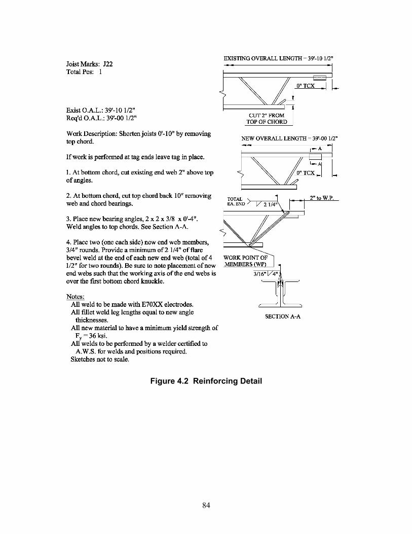
84
Figure 4.2 Reinforcing Detail
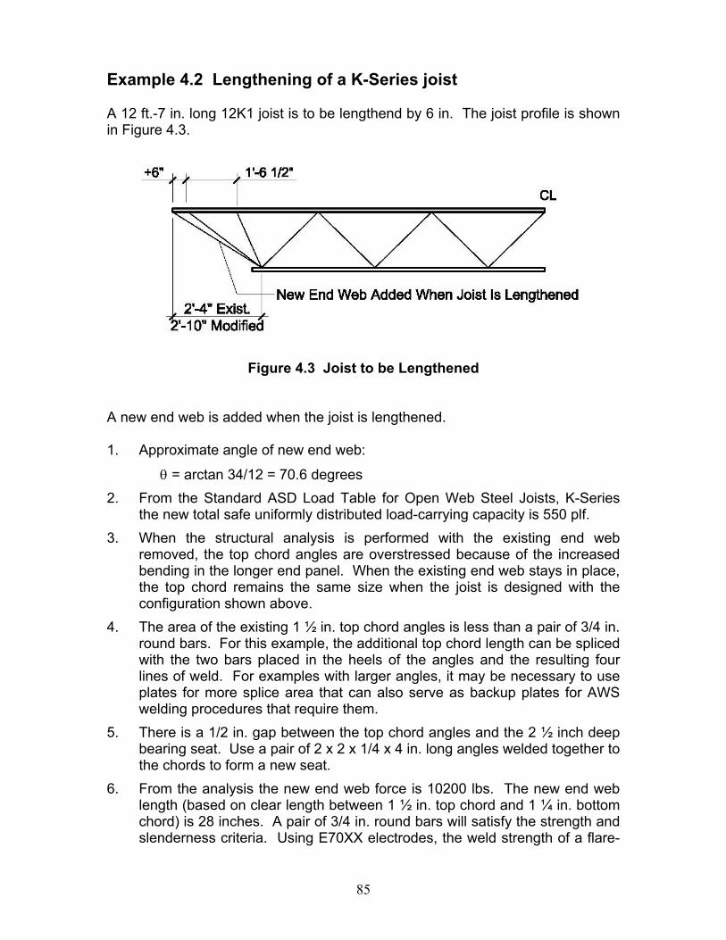
85
Example 4.2 Lengthening of a K-Series joist A 12 ft.-7 in. long 12K1 joist is to be lengthend by 6 in. The joist profile is shown in Figure 4.3.
Figure 4.3 Joist to be Lengthened
A new end web is added when the joist is lengthened. 1. Approximate angle of new end web:
θ = arctan 34/12 = 70.6 degrees 2. From the Standard ASD Load Table for Open Web Steel Joists, K-Series
the new total safe uniformly distributed load-carrying capacity is 550 plf. 3. When the structural analysis is performed with the existing end web
removed, the top chord angles are overstressed because of the increased bending in the longer end panel. When the existing end web stays in place, the top chord remains the same size when the joist is designed with the configuration shown above.
4. The area of the existing 1 ½ in. top chord angles is less than a pair of 3/4 in. round bars. For this example, the additional top chord length can be spliced with the two bars placed in the heels of the angles and the resulting four lines of weld. For examples with larger angles, it may be necessary to use plates for more splice area that can also serve as backup plates for AWS welding procedures that require them.
5. There is a 1/2 in. gap between the top chord angles and the 2 ½ inch deep bearing seat. Use a pair of 2 x 2 x 1/4 x 4 in. long angles welded together to the chords to form a new seat.
6. From the analysis the new end web force is 10200 lbs. The new end web length (based on clear length between 1 ½ in. top chord and 1 ¼ in. bottom chord) is 28 inches. A pair of 3/4 in. round bars will satisfy the strength and slenderness criteria. Using E70XX electrodes, the weld strength of a flare-
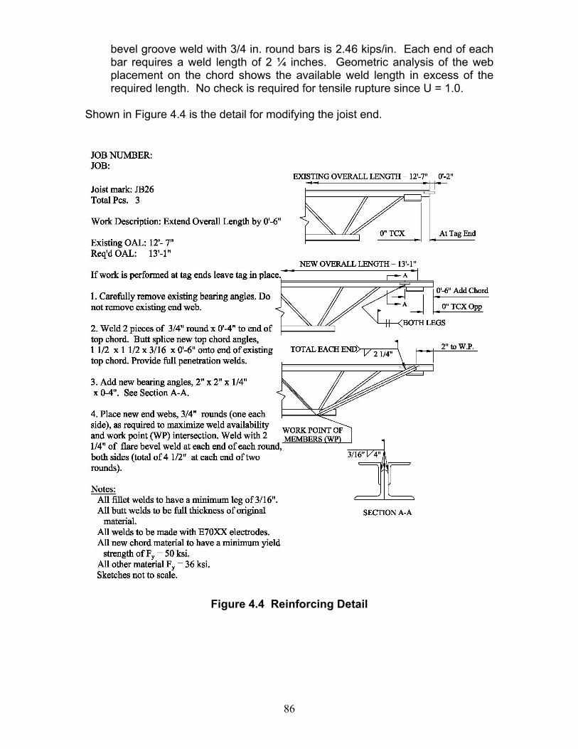
86
bevel groove weld with 3/4 in. round bars is 2.46 kips/in. Each end of each bar requires a weld length of 2 ¼ inches. Geometric analysis of the web placement on the chord shows the available weld length in excess of the required length. No check is required for tensile rupture since U = 1.0.
Shown in Figure 4.4 is the detail for modifying the joist end.
Figure 4.4 Reinforcing Detail
87
CHAPTER 5
OTHER CONSIDERATIONS There are a number of other topics that should be considered when making joist modifications. DEFLECTIONS The topic of deflection is mentioned here primarily as a reminder to the designer, that in addition to strengthening joists for load, deflection control is often required for the joists that have been modified or strengthened. In some cases stiffening of joists may be required for new equipment, or to change the natural frequency of a joist system. Deflection criteria must also be taken into consideration when joists are modified for added load, lengthened, or otherwise altered. Project deflection requirements must be considered. For example, a live load deflection of less than L/240 may not be met if a joist is only strengthened for added loads from a snow drift. CAMBER When shortening or lengthening a joist, camber needs to be maintained whenever removing any web members. EFFECTS OF ADDED LOADS ON BRIDGING Depending on the type of modification being used, the designer must investigate whether bridging needs to be added or altered. Providing lateral support to the compression chord members is critical. Keep in mind also that the bottom chord may be subject to compression during wind uplift. The designer is referred to the SJI Specifications for bridging requirements. CREATING TWO JOISTS FROM ONE Occasionally a joist needs to be cut near the center to make two joists from one (e.g. possibly to make room for an added elevator shaft). When this is done it is similar to shortening a joist. Due to the increased shear and possible stress reversal, many of the joist webs will likely require reinforcing.
88
Example 5.1 Changing the Natural Frequency of a Joist System 24K7 joists span 40 ft. on the roof of an office facility. The joists are supported by masonry walls. A new roof top unit (RTU) was installed at mid-span of the joists and the load from the RTU is approximately 2 kips on each joist. It was determined that the joists did not need reinforcing, due to the 2 kip load. However, after the installation, the roof joists were vibrating noticeably. The owner of the facility did not want to install isolators under the unit, so it was decided to change the natural frequency of the joist system. The natural frequency of a beam or joist is directly related to the stiffness of the beam or joist, thus directly related to the deflection of the joist. The vibration problem can usually be mitigated, by providing a frequency of the support system of at least fifty percent greater than the frequency of the RTU. It was determined from the RTU manufacturer, that the natural frequency of the RTU is 3.6 Hertz. Determine what reinforcement must be added to each supporting joist in order to reduce the vibration to an acceptable level. Determine the natural frequency of the joist system. The natural frequency, f, of the joist under a concentrated mid-span load is approximately
orWLEIg
293.6f 3π
= ∆188 (cycles per minute) Eq. 5-1
where ∆ equals the joist deflection at mid-span in inches (Young and Budynas 2000). The moment of inertia of the 24K7 joist can be determined from the SJI Standard ASD Load Table for Open Web Steel Joists, K-Series. From the text preceding the table, the following equation is given:
( )( )( )63LLj 10LW767.26I −= Eq. 5-2
where, WLL = RED figure in the Load Table and L = (Span - 0.33) in feet
From the Load Table WLL = 148 plf.
( )( )( ) 363j .in2471067.39148767.26I == −
The maximum deflection of an open web steel joist under a concentrated load at mid-span is
EI48PL15.1 3
max =∆ Eq. 5-3
The 1.15 factor in the equation above is used to account for the additional deformation in the joist web members thus,
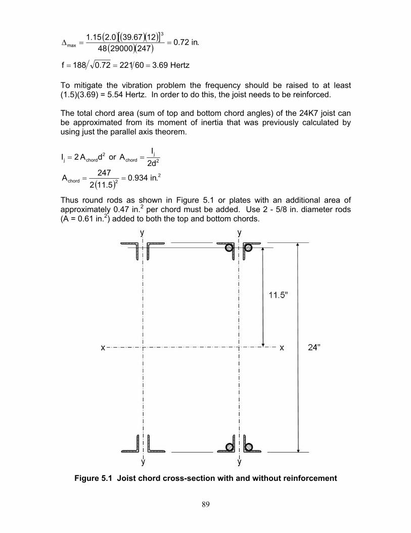
89
( ) ( )( )[ ]( )( ) .in72.0
24729000481267.390.215.1 3
max ==∆
Hertz69.36022172.0188f === To mitigate the vibration problem the frequency should be raised to at least (1.5)(3.69) = 5.54 Hertz. In order to do this, the joist needs to be reinforced. The total chord area (sum of top and bottom chord angles) of the 24K7 joist can be approximated from its moment of inertia that was previously calculated by using just the parallel axis theorem.
2j
chord2
chordj d2I
AordA2I ==
( )2
2chord .in934.05.112
247A ==
Thus round rods as shown in Figure 5.1 or plates with an additional area of approximately 0.47 in.2 per chord must be added. Use 2 - 5/8 in. diameter rods (A = 0.61 in.2) added to both the top and bottom chords.
Figure 5.1 Joist chord cross-section with and without reinforcement
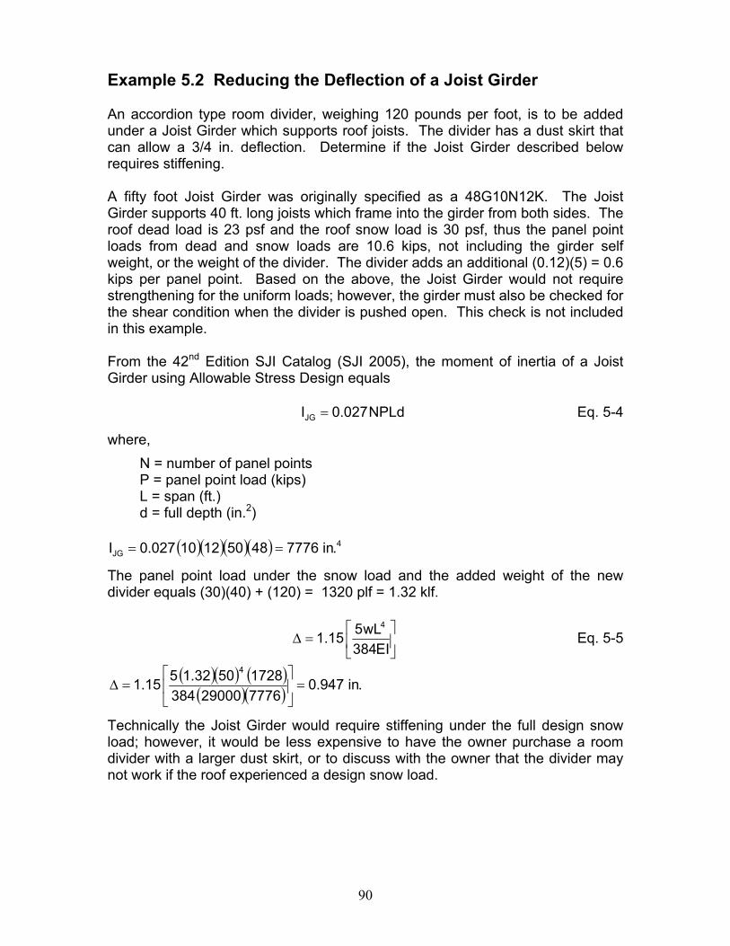
90
Example 5.2 Reducing the Deflection of a Joist Girder An accordion type room divider, weighing 120 pounds per foot, is to be added under a Joist Girder which supports roof joists. The divider has a dust skirt that can allow a 3/4 in. deflection. Determine if the Joist Girder described below requires stiffening. A fifty foot Joist Girder was originally specified as a 48G10N12K. The Joist Girder supports 40 ft. long joists which frame into the girder from both sides. The roof dead load is 23 psf and the roof snow load is 30 psf, thus the panel point loads from dead and snow loads are 10.6 kips, not including the girder self weight, or the weight of the divider. The divider adds an additional (0.12)(5) = 0.6 kips per panel point. Based on the above, the Joist Girder would not require strengthening for the uniform loads; however, the girder must also be checked for the shear condition when the divider is pushed open. This check is not included in this example. From the 42nd Edition SJI Catalog (SJI 2005), the moment of inertia of a Joist Girder using Allowable Stress Design equals
NPLd027.0IJG = Eq. 5-4
where, N = number of panel points P = panel point load (kips) L = span (ft.) d = full depth (in.2)
( )( )( )( ) 4
JG .in777648501210027.0I ==
The panel point load under the snow load and the added weight of the new divider equals (30)(40) + (120) = 1320 plf = 1.32 klf.
⎥⎦
⎤⎢⎣
⎡=∆
EI384wL515.1
4
Eq. 5-5
( )( ) ( )( )( ) .in947.0
77762900038417285032.1515.1
4
=⎥⎦
⎤⎢⎣
⎡=∆
Technically the Joist Girder would require stiffening under the full design snow load; however, it would be less expensive to have the owner purchase a room divider with a larger dust skirt, or to discuss with the owner that the divider may not work if the roof experienced a design snow load.
91
CHAPTER 6
SUMMARY Approaches for the modification and strengthening of steel joists have been presented. Several types of reinforcing members have been suggested along with recommended attachment details. The procedures and details presented do not constitute an exhaustive list of how reinforcement can be designed and detailed; however, they provide the designer with ideas and concepts to solve individual joist modification or strengthening requirements.
92
REFERENCES
AISC (2005), Steel Construction Manual, Thirteenth Edition, American Institute of Steel Construction, Chicago, IL.
AISC (2005), Specification for Structural Steel Buildings, March 9, 2005,
American Institute of Steel Construction, Chicago, IL. Seely, Fred B. and Smith, James O. (1952), Advanced Mechanics of Materials,
Second Edition, John Wiley and Sons, Inc., New York, NY. SJI (2003), 75-Year Steel Joist Manual, Steel Joist Institute, Myrtle Beach, SC. SJI (2005), 42nd Edition Catalog containing Standard Specifications, Load
Tables and Weight Tables for Steel Joists and Joist Girders: K-Series, LH-Series, DLH-Series, Joist Girders, Steel Joist Institute, Myrtle Beach, SC.
Young, Warren C. and Budynas, Richard G. (2000), Roark’s Formulas for
Stress and Strain, McGraw-Hill Education, New York, NY.
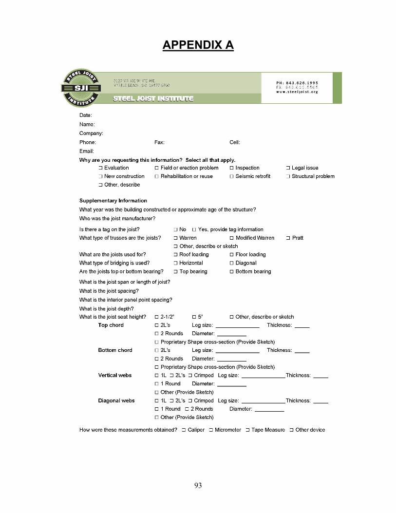
93
APPENDIX A
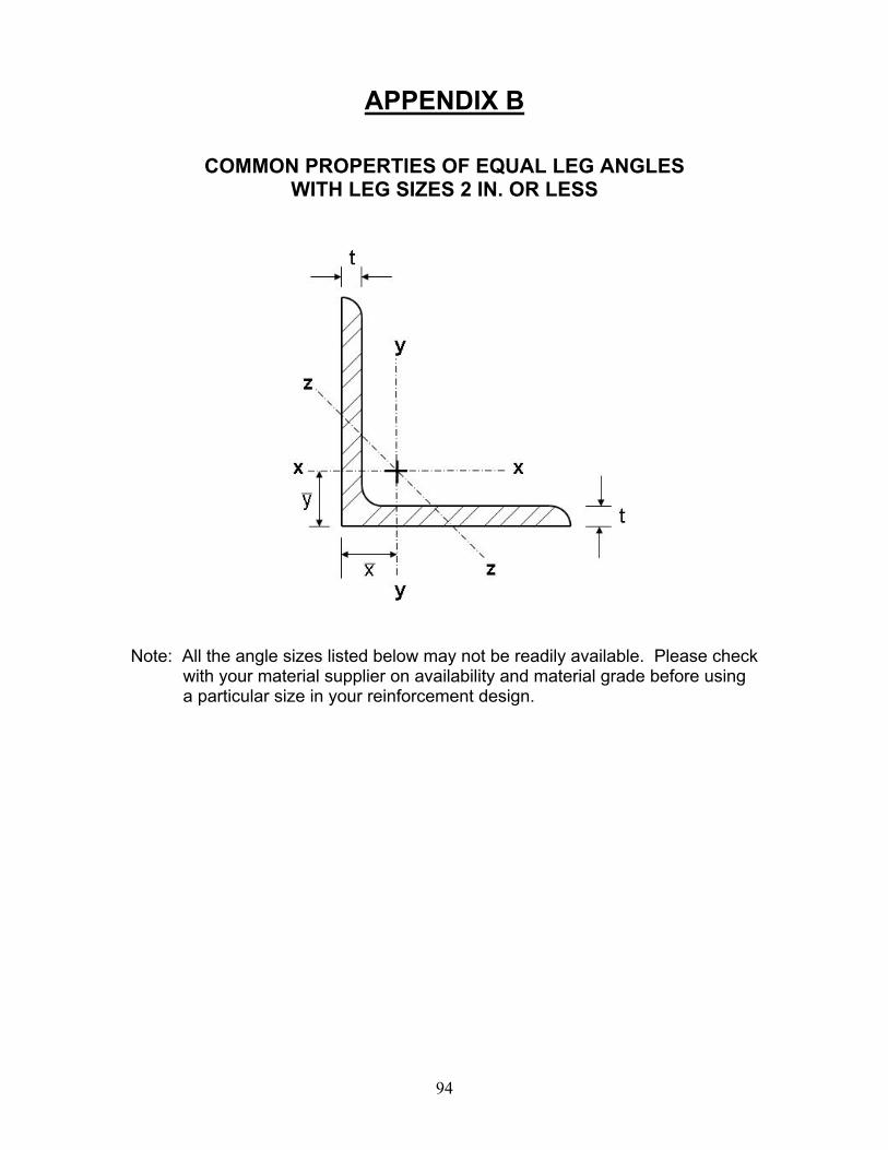
94
APPENDIX B
COMMON PROPERTIES OF EQUAL LEG ANGLES
WITH LEG SIZES 2 IN. OR LESS
Note: All the angle sizes listed below may not be readily available. Please check
with your material supplier on availability and material grade before using a particular size in your reinforcement design.
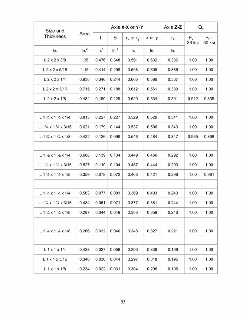
95
Axis X-X or Y-Y Axis Z-Z Qs Size and Thickness Area
I S rx or ry yorx rz
In. In.2 In.4 In.3 In. In. In.
Fy = 36 ksi
Fy = 50 ksi
L 2 x 2 x 3/8 1.36 0.476 0.348 0.591 0.632 0.386 1.00 1.00
L 2 x 2 x 5/16 1.15 0.414 0.298 0.598 0.609 0.386 1.00 1.00
L 2 x 2 x 1/4 0.938 0.346 0.244 0.605 0.586 0.387 1.00 1.00
L 2 x 2 x 3/16 0.715 0.271 0.188 0.612 0.561 0.389 1.00 1.00
L 2 x 2 x 1/8 0.484 0.189 0.129 0.620 0.534 0.391 0.912 0.835
L 1 ¾ x 1 ¾ x 1/4 0.813 0.227 0.227 0.529 0.529 0.341 1.00 1.00
L 1 ¾ x 1 ¾ x 3/16 0.621 0.179 0.144 0.537 0.506 0.343 1.00 1.00
L 1 ¾ x 1 ¾ x 1/8 0.422 0.126 0.099 0.546 0.484 0.347 0.965 0.898
L 1 ½ x 1 ½ x 1/4 0.688 0.139 0.134 0.449 0.466 0.292 1.00 1.00
L 1 ½ x 1 ½ x 3/16 0.527 0.110 0.104 0.457 0.444 0.293 1.00 1.00
L 1 ½ x 1 ½ x 1/8 0.359 0.078 0.072 0.465 0.421 0.296 1.00 0.961
L 1 ¼ x 1 ¼ x 1/4 0.563 0.077 0.091 0.369 0.403 0.243 1.00 1.00
L 1 ¼ x 1 ¼ x 3/16 0.434 0.061 0.071 0.377 0.381 0.244 1.00 1.00
L 1 ¼ x 1 ¼ x 1/8 0.297 0.044 0.049 0.385 0.359 0.246 1.00 1.00
L 1 ⅛ x 1 ⅛ x 1/8 0.266 0.032 0.040 0.345 0.327 0.221 1.00 1.00
L 1 x 1 x 1/4 0.438 0.037 0.056 0.290 0.339 0.196 1.00 1.00
L 1 x 1 x 3/16 0.340 0.030 0.044 0.297 0.318 0.195 1.00 1.00
L 1 x 1 x 1/8 0.234 0.022 0.031 0.304 0.296 0.196 1.00 1.00
Steel Joist Institute Technical Digest 12 Evaluation and Modification of Open-Web Steel Joists
and Joist Girders
First Printing – February 2007
This document containing the errata to the Steel Joist Institute Technical Digest 12, Evaluation and Modification of Open-Web Steel Joists and Joist Girders will be periodically updated as needed and posted on the SJI website at www.steeljoist.org . The errata are organized by date in descending order (most recent to furthest past) hence regular users of this document need only review the errata posted since their previous use.
Errata Posted on August 24, 2007 Example 2.2 Load distribution for roof top units (interior joist),
page 10, paragraph 2 revise as follows: A new roof top unit is to be located on top of existing 30H8 joists. The building was erected in 1975. The joists span 40 feet and are 6 5 ft. on center. A sketch indicating the location of the loads from the roof top unit is shown in Figure 2.2. The reactions from the unit and the curbing are also shown in the figure. Figure 2.3 shows the location and suggested geometry of the transfer truss. Replace Figures 2.2 and 2.3 on page 11 with the following:
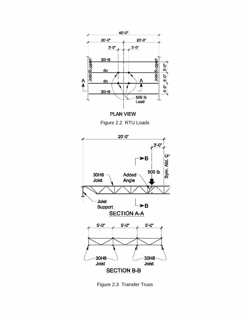
Figure 2.2 RTU Loads
Figure 2.3 Transfer Truss

Steel Joist Institute Technical Digest 12 Evaluation and Modification of Open-Web Steel Joists
and Joist Girders
First Printing – February 2007
This document containing the errata to the Steel Joist Institute Technical Digest 12, Evaluation and Modification of Open-Web Steel Joists and Joist Girders will be periodically updated as needed and posted on the SJI website at www.steeljoist.org . The errata are organized by date in descending order (most recent to furthest past) hence regular users of this document need only review the errata posted since their previous use.
First Errata Posted on August 24, 2007 Second Errata Posted on March 16, 2009
Example 3.5 Strengthening of a LH-Series joist with double angle webs
Design Approach Part 5. Check buckling of the reinforcing member, page 77 is being revised as follows:
5. Check buckling of the reinforcing:
Check buckling of the 3/4 in. diameter reinforcing rod between welds. L = weld spacing – weld length = 12 – 2 = 10 in.
187.0442.0
0155.0AIr ===
Slenderness ratio of the rod is:
4.53187.010
rL
==
( ) ksi09.100
187.01029000F 2
2
e =
⎟⎠⎞
⎜⎝⎛
π=
ksi97.3036658.0F 09.10036
cr =⎥⎦
⎤⎢⎣
⎡=
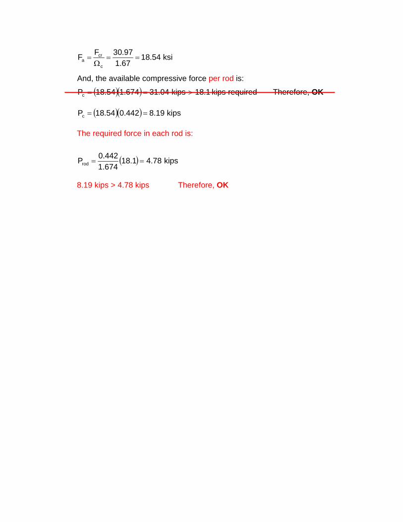
ksi54.1867.197.30FF
c
cra ==
Ω=
And, the available compressive force per rod is:
( )( ) requiredkips1.18kips04.31674.154.18Pc >== Therefore, OK
( )( ) kips19.8442.054.18Pc == The required force in each rod is:
( ) kips78.41.18674.1442.0Prod ==
8.19 kips > 4.78 kips Therefore, OK

Steel Joist Institute Technical Digest 12 Evaluation and Modification of Open-Web Steel Joists
and Joist Girders
First Printing – February 2007
This document containing the errata to the Steel Joist Institute Technical Digest 12, Evaluation and Modification of Open-Web Steel Joists and Joist Girders will be periodically updated as needed and posted on the SJI website at www.steeljoist.org . The errata are organized by date in descending order (most recent to furthest past) hence regular users of this document need only review the errata posted since their previous use.
First Errata Posted on August 24, 2007 Second Errata Posted on March 16, 2009
Third Errata Posted on December 15, 2011 Revised page 50 to include revised Figure 3.26 regarding bottom chord weld lengths.
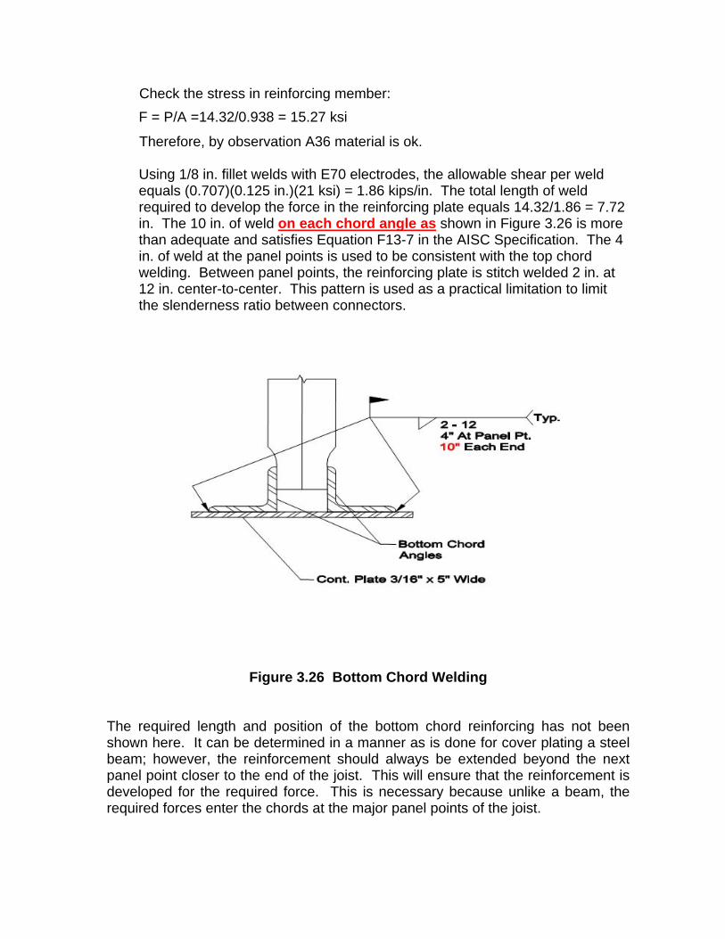
Check the stress in reinforcing member: F = P/A =14.32/0.938 = 15.27 ksi
Therefore, by observation A36 material is ok.
Using 1/8 in. fillet welds with E70 electrodes, the allowable shear per weld equals (0.707)(0.125 in.)(21 ksi) = 1.86 kips/in. The total length of weld required to develop the force in the reinforcing plate equals 14.32/1.86 = 7.72 in. The 10 in. of weld on each chord angle as shown in Figure 3.26 is more than adequate and satisfies Equation F13-7 in the AISC Specification. The 4 in. of weld at the panel points is used to be consistent with the top chord welding. Between panel points, the reinforcing plate is stitch welded 2 in. at 12 in. center-to-center. This pattern is used as a practical limitation to limit the slenderness ratio between connectors.
Figure 3.26 Bottom Chord Welding
The required length and position of the bottom chord reinforcing has not been shown here. It can be determined in a manner as is done for cover plating a steel beam; however, the reinforcement should always be extended beyond the next panel point closer to the end of the joist. This will ensure that the reinforcement is developed for the required force. This is necessary because unlike a beam, the required forces enter the chords at the major panel points of the joist.