Embed Size (px)
Citation preview

SANDVIK Roadheader MR341 manual controlled – (ATEX)
Page 1 of 33
www.sandvik.com
Technical description-MR341 ATEX Basic Machine Specification 2014.509 _Rev. 1
Technical Description
Basic Machine
SANDVIK Roadheader MR341 manual controlled – (ATEX)
Page 2 of 33
www.sandvik.com
Technical description-MR341 ATEX Basic Machine Specification 2014.509 _Rev. 1
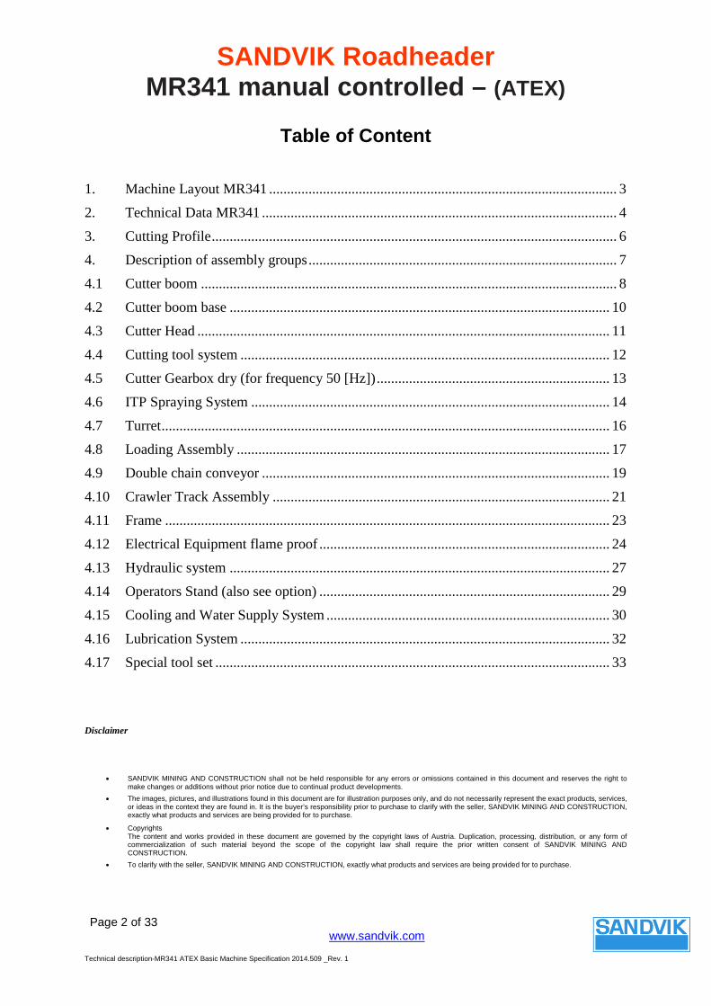
Table of Content
1. Machine Layout MR341 ................................................................................................. 3
2. Technical Data MR341 ................................................................................................... 4
3. Cutting Profile ................................................................................................................. 6
4. Description of assembly groups ...................................................................................... 7
4.1 Cutter boom .................................................................................................................... 8
4.2 Cutter boom base .......................................................................................................... 10
4.3 Cutter Head ................................................................................................................... 11
4.4 Cutting tool system ....................................................................................................... 12
4.5 Cutter Gearbox dry (for frequency 50 [Hz]) ................................................................. 13
4.6 ITP Spraying System .................................................................................................... 14
4.7 Turret ............................................................................................................................. 16
4.8 Loading Assembly ........................................................................................................ 17
4.9 Double chain conveyor ................................................................................................. 19
4.10 Crawler Track Assembly .............................................................................................. 21
4.11 Frame ............................................................................................................................ 23
4.12 Electrical Equipment flame proof ................................................................................. 24
4.13 Hydraulic system .......................................................................................................... 27
4.14 Operators Stand (also see option) ................................................................................. 29
4.15 Cooling and Water Supply System ............................................................................... 30
4.16 Lubrication System ....................................................................................................... 32
4.17 Special tool set .............................................................................................................. 33
Disclaimer
• SANDVIK MINING AND CONSTRUCTION shall not be held responsible for any errors or omissions contained in this document and reserves the right to make changes or additions without prior notice due to continual product developments.
• The images, pictures, and illustrations found in this document are for illustration purposes only, and do not necessarily represent the exact products, services, or ideas in the context they are found in. It is the buyer’s responsibility prior to purchase to clarify with the seller, SANDVIK MINING AND CONSTRUCTION, exactly what products and services are being provided for to purchase.
• Copyrights The content and works provided in these document are governed by the copyright laws of Austria. Duplication, processing, distribution, or any form of commercialization of such material beyond the scope of the copyright law shall require the prior written consent of SANDVIK MINING AND CONSTRUCTION.
• To clarify with the seller, SANDVIK MINING AND CONSTRUCTION, exactly what products and services are being provided for to purchase.
SANDVIK Roadheader MR341 manual controlled – (ATEX)
Page 3 of 33
www.sandvik.com
Technical description-MR341 ATEX Basic Machine Specification 2014.509 _Rev. 1
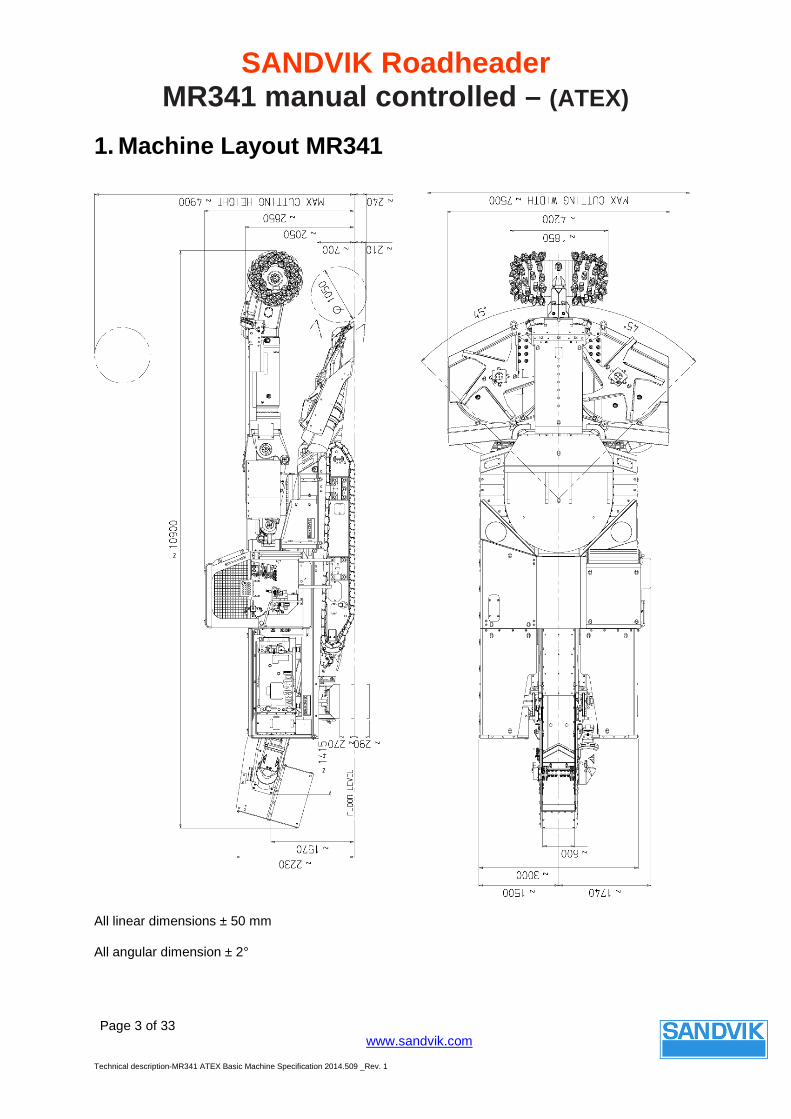
1. Machine Layout MR341
All linear dimensions ± 50 mm
All angular dimension ± 2°

SANDVIK Roadheader MR341 manual controlled – (ATEX)
Page 4 of 33
www.sandvik.com
Technical description-MR341 ATEX Basic Machine Specification 2014.509 _Rev. 1
2. Technical Data MR341
Cutting system Cutting height above track level, max [mm] 4.900 Cutting width, horizontal [mm] 7.500 Undercut below track level [mm] 240 Cross section, above track level [m²] 34 Adjustment of loading table
above floor level [mm] 700 below floor level [mm] 210
Spraying system [ITP]
water quantity min. [l/min] 39 water pressure min. [bar] 11-20
Navigable Area of Application Cone radius [m] 25 Basin radius [°] 20 Slope side in rock, max. [°] ± 5 Incline/Decline, max. [°] ± 18 Geometric Characteristics Slewing of cutter boom [°] ± 45 Vertical lifting from horizontal upwards [°] 63.2 Vertical lowering from horizontal downwards [°] 22.3 Forces Traction force per track (theoretical force on drive sprocket [kN] 624
General MR341 Total weight (metric tons, approx.) [t] 60 Total length [m] 10.9 Height over turret [mm] 2050 Height over operator stand [mm] 2850 Machine width over tracks [mm] 2600 Machine width without loading table [mm] 3240 Loading table width [mm] 4200 Crawler track width [mm] 600 Machine ground pressure [MPa] 0.17 Ground clearance [mm] 260
SANDVIK Roadheader MR341 manual controlled – (ATEX)
Page 5 of 33
www.sandvik.com
Technical description-MR341 ATEX Basic Machine Specification 2014.509 _Rev. 1
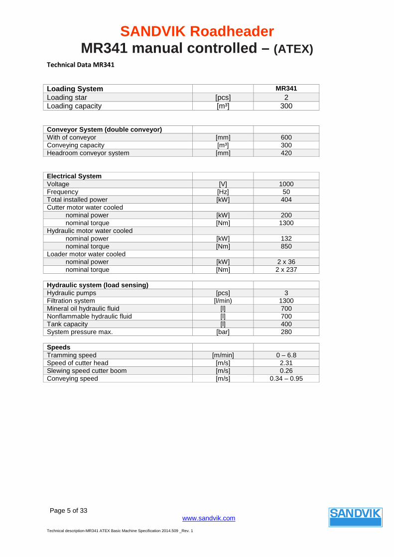
Technical Data MR341
Loading System MR341 Loading star [pcs] 2 Loading capacity [m³] 300
Conveyor System (double conveyor) With of conveyor [mm] 600 Conveying capacity [m³] 300 Headroom conveyor system [mm] 420
Electrical System Voltage [V] 1000 Frequency [Hz] 50 Total installed power [kW] 404 Cutter motor water cooled
nominal power [kW] 200 nominal torque [Nm] 1300
Hydraulic motor water cooled nominal power [kW] 132 nominal torque [Nm] 850
Loader motor water cooled nominal power [kW] 2 x 36 nominal torque [Nm] 2 x 237
Hydraulic system (load sensing) Hydraulic pumps [pcs] 3 Filtration system [l/min) 1300 Mineral oil hydraulic fluid [l] 700 Nonflammable hydraulic fluid [l] 700 Tank capacity [l] 400 System pressure max. [bar] 280 Speeds Tramming speed [m/min] 0 – 6.8 Speed of cutter head [m/s] 2.31 Slewing speed cutter boom [m/s] 0.26 Conveying speed [m/s] 0.34 – 0.95
SANDVIK Roadheader MR341 manual controlled – (ATEX)
Page 6 of 33
www.sandvik.com
Technical description-MR341 ATEX Basic Machine Specification 2014.509 _Rev. 1
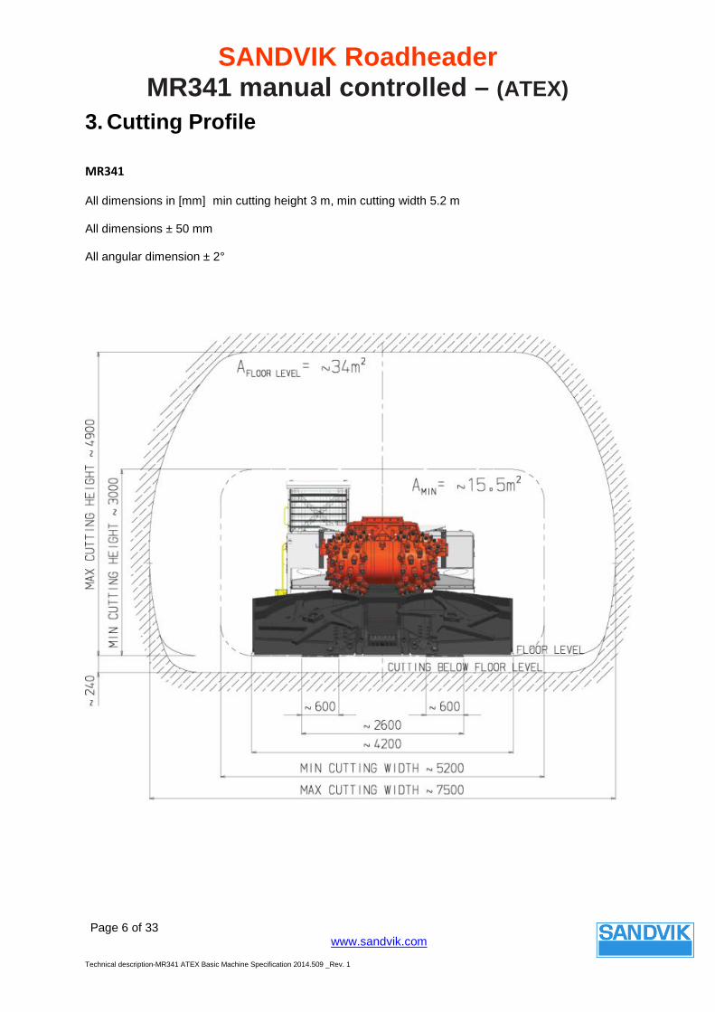
3. Cutting Profile
MR341
All dimensions in [mm] min cutting height 3 m, min cutting width 5.2 m
All dimensions ± 50 mm
All angular dimension ± 2°
SANDVIK Roadheader MR341 manual controlled – (ATEX)
Page 7 of 33
www.sandvik.com
Technical description-MR341 ATEX Basic Machine Specification 2014.509 _Rev. 1
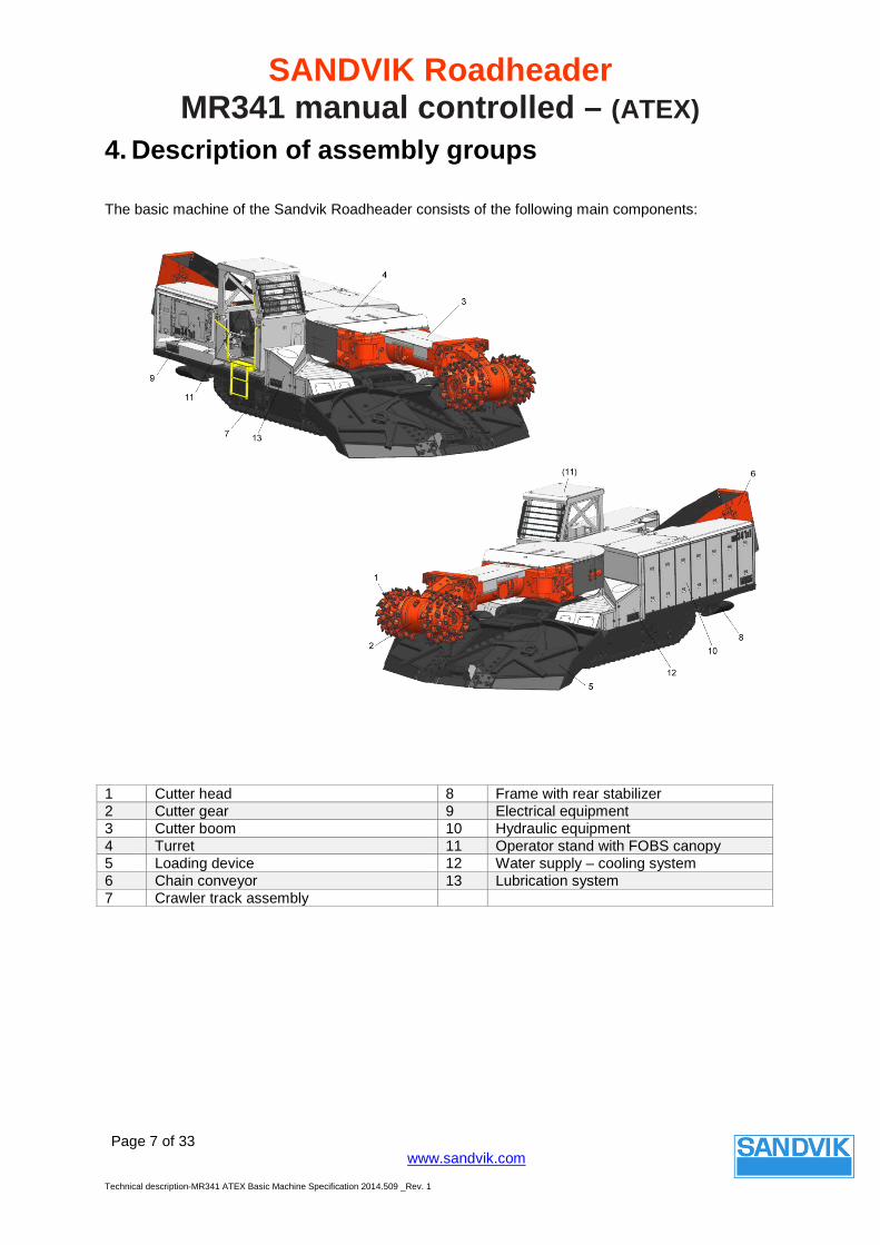
4. Description of assembly groups
The basic machine of the Sandvik Roadheader consists of the following main components:
1 Cutter head 8 Frame with rear stabilizer 2 Cutter gear 9 Electrical equipment 3 Cutter boom 10 Hydraulic equipment 4 Turret 11 Operator stand with FOBS canopy 5 Loading device 12 Water supply – cooling system 6 Chain conveyor 13 Lubrication system 7 Crawler track assembly
SANDVIK Roadheader MR341 manual controlled – (ATEX)
Page 8 of 33
www.sandvik.com
Technical description-MR341 ATEX Basic Machine Specification 2014.509 _Rev. 1
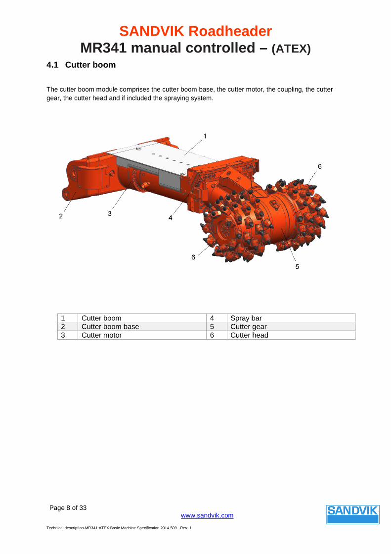
4.1 Cutter boom
The cutter boom module comprises the cutter boom base, the cutter motor, the coupling, the cutter gear, the cutter head and if included the spraying system.
1 Cutter boom 4 Spray bar 2 Cutter boom base 5 Cutter gear 3 Cutter motor 6 Cutter head

SANDVIK Roadheader MR341 manual controlled – (ATEX)
Page 9 of 33
www.sandvik.com
Technical description-MR341 ATEX Basic Machine Specification 2014.509 _Rev. 1
Cutter boom
1 Cutter boom The cutter boom module comprises the cutter boom base, the cutter motor, the coupling (cardan shaft), the cutter gear, the cutter head and if included the spraying system
2 Cutter boom base A steel construction mounted to the turret. It is used to support the motor and attaches the vertical pivoting cylinders.
3 Cutter motor Self supporting design, water cooled. 4 Spraying system The basic machine is equipped with a spraying system,
using specific “ITP” hollow cone spray nozzles (incendive Temperature Potential). The system consists of spraying nozzles for the cutter head and for the loading table For different spraying system - see Options.
5 Cutter gear The gearbox consists of one cardan shaft, one bevel gear stage and one planetary gear stage and an oil circulation pump. Input shaft sealed with radial shaft gasket. Output shaft is sealed with mechanical face seals Cutter gear is available in different specification: Dry transmission: At basic machine, if the machine is used with external spraying system only. Wet transmission: With integrated water channels for supplying the cutter head with water. See Options
6 Cutter head Consists of two cutter head halves, which are attached to the output shaft of the cutter gear. The cutter head halves are connected to each other via multiple spline shafts. Different cutter heads available. See Options
SANDVIK Roadheader MR341 manual controlled – (ATEX)
Page 10 of 33
www.sandvik.com
Technical description-MR341 ATEX Basic Machine Specification 2014.509 _Rev. 1
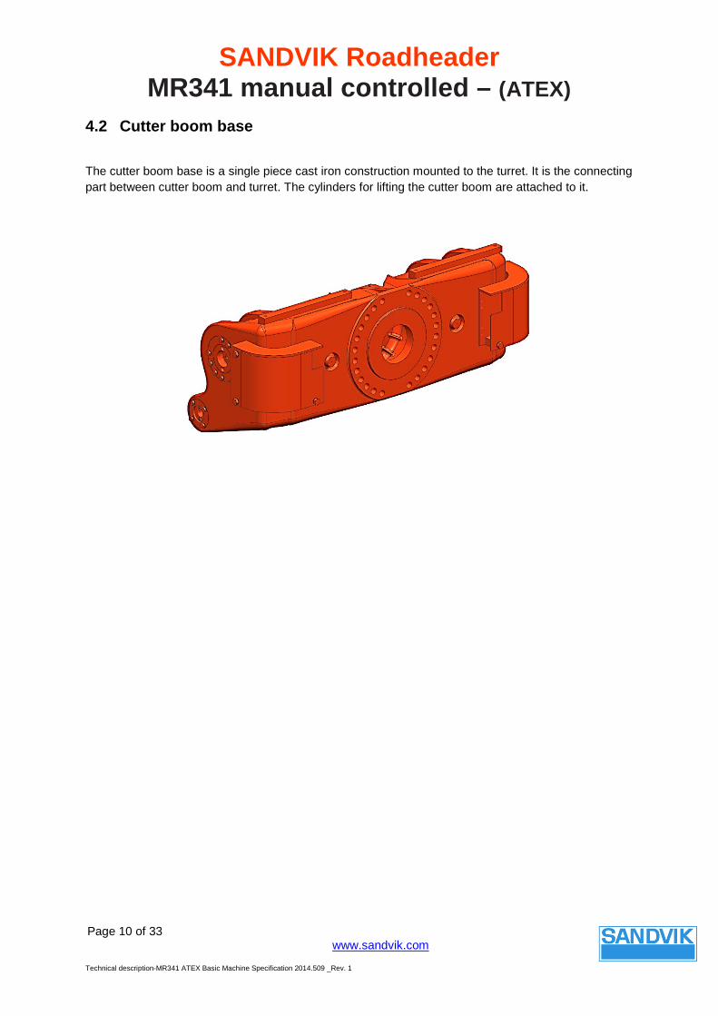
4.2 Cutter boom base
The cutter boom base is a single piece cast iron construction mounted to the turret. It is the connecting part between cutter boom and turret. The cylinders for lifting the cutter boom are attached to it.
SANDVIK Roadheader MR341 manual controlled – (ATEX)
Page 11 of 33
www.sandvik.com
Technical description-MR341 ATEX Basic Machine Specification 2014.509 _Rev. 1
4.3 Cutter Head
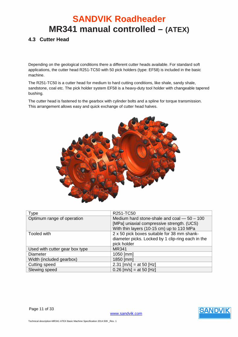
Depending on the geological conditions there a different cutter heads available. For standard soft applications, the cutter head R251-TC50 with 50 pick holders (type: EF58) is included in the basic machine.
The R251-TC50 is a cutter head for medium to hard cutting conditions, like shale, sandy shale, sandstone, coal etc. The pick holder system EF58 is a heavy-duty tool holder with changeable tapered bushing.
The cutter head is fastened to the gearbox with cylinder bolts and a spline for torque transmission. This arrangement allows easy and quick exchange of cutter head halves.
Type R251-TC50 Optimum range of operation Medium hard stone-shale and coal — 50 – 100
[MPa] uniaxial compressive strength. (UCS) With thin layers (10-15 cm) up to 110 MPa
Tooled with 2 x 50 pick boxes suitable for 38 mm shank-diameter picks. Locked by 1 clip-ring each in the pick holder
Used with cutter gear box type MR341 Diameter 1050 [mm] Width (included gearbox) 1850 [mm] Cutting speed 2.31 [m/s] = at 50 [Hz] Slewing speed 0.26 [m/s] = at 50 [Hz]
SANDVIK Roadheader MR341 manual controlled – (ATEX)
Page 12 of 33
www.sandvik.com
Technical description-MR341 ATEX Basic Machine Specification 2014.509 _Rev. 1
4.4 Cutting tool system
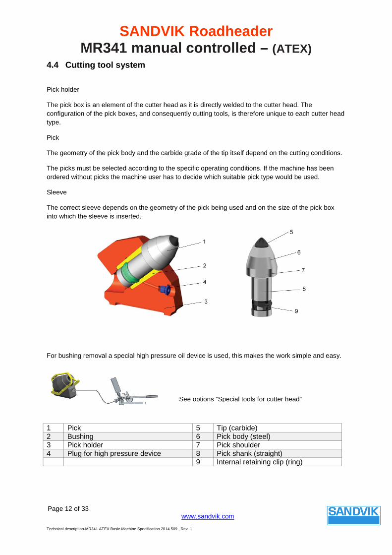
Pick holder
The pick box is an element of the cutter head as it is directly welded to the cutter head. The configuration of the pick boxes, and consequently cutting tools, is therefore unique to each cutter head type.
Pick
The geometry of the pick body and the carbide grade of the tip itself depend on the cutting conditions.
The picks must be selected according to the specific operating conditions. If the machine has been ordered without picks the machine user has to decide which suitable pick type would be used.
Sleeve
The correct sleeve depends on the geometry of the pick being used and on the size of the pick box into which the sleeve is inserted.
For bushing removal a special high pressure oil device is used, this makes the work simple and easy.
1 Pick 5 Tip (carbide) 2 Bushing 6 Pick body (steel) 3 Pick holder 7 Pick shoulder 4 Plug for high pressure device 8 Pick shank (straight) 9 Internal retaining clip (ring)
See options ”Special tools for cutter head”
SANDVIK Roadheader MR341 manual controlled – (ATEX)
Page 13 of 33
www.sandvik.com
Technical description-MR341 ATEX Basic Machine Specification 2014.509 _Rev. 1
4.5 Cutter Gearbox dry (for frequency 50 [Hz])
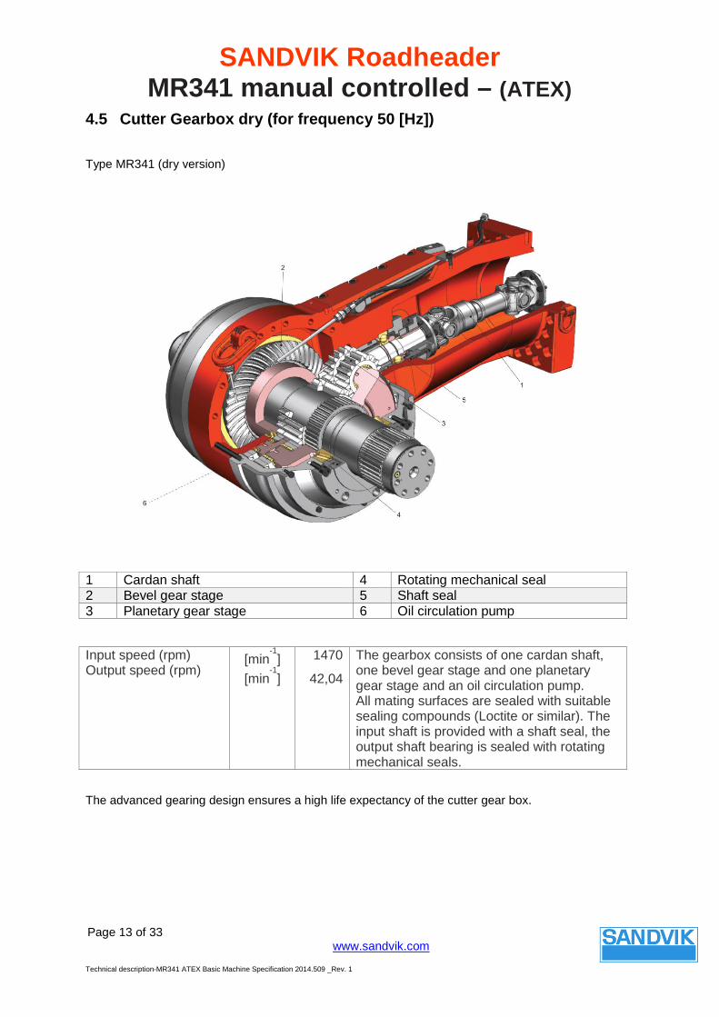
Type MR341 (dry version)
Input speed (rpm) Output speed (rpm) [min
-1]
[min-1]
1470
42,04 The gearbox consists of one cardan shaft, one bevel gear stage and one planetary gear stage and an oil circulation pump. All mating surfaces are sealed with suitable sealing compounds (Loctite or similar). The input shaft is provided with a shaft seal, the output shaft bearing is sealed with rotating mechanical seals.
The advanced gearing design ensures a high life expectancy of the cutter gear box.
1 Cardan shaft 4 Rotating mechanical seal 2 Bevel gear stage 5 Shaft seal 3 Planetary gear stage 6 Oil circulation pump
SANDVIK Roadheader MR341 manual controlled – (ATEX)
Page 14 of 33
www.sandvik.com
Technical description-MR341 ATEX Basic Machine Specification 2014.509 _Rev. 1
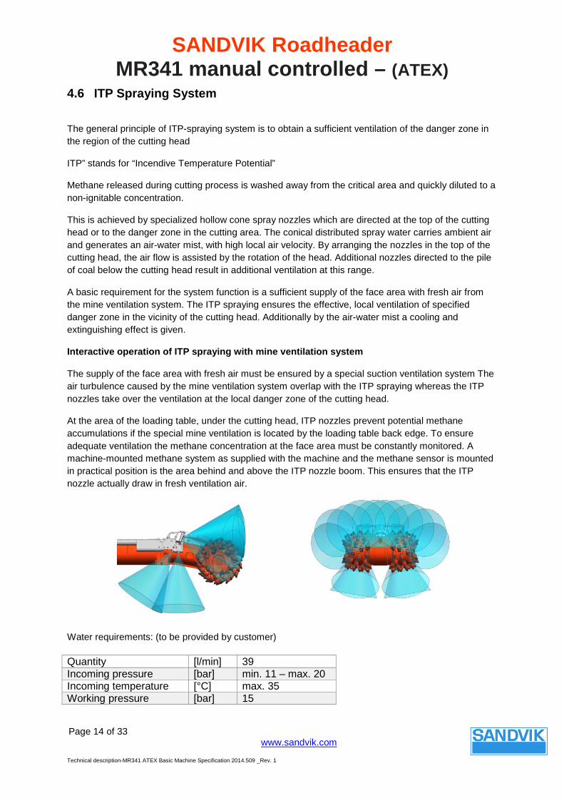
4.6 ITP Spraying System
The general principle of ITP-spraying system is to obtain a sufficient ventilation of the danger zone in the region of the cutting head
ITP” stands for “Incendive Temperature Potential”
Methane released during cutting process is washed away from the critical area and quickly diluted to a non-ignitable concentration.
This is achieved by specialized hollow cone spray nozzles which are directed at the top of the cutting head or to the danger zone in the cutting area. The conical distributed spray water carries ambient air and generates an air-water mist, with high local air velocity. By arranging the nozzles in the top of the cutting head, the air flow is assisted by the rotation of the head. Additional nozzles directed to the pile of coal below the cutting head result in additional ventilation at this range.
A basic requirement for the system function is a sufficient supply of the face area with fresh air from the mine ventilation system. The ITP spraying ensures the effective, local ventilation of specified danger zone in the vicinity of the cutting head. Additionally by the air-water mist a cooling and extinguishing effect is given.
Interactive operation of ITP spraying with mine ventilation system
The supply of the face area with fresh air must be ensured by a special suction ventilation system The air turbulence caused by the mine ventilation system overlap with the ITP spraying whereas the ITP nozzles take over the ventilation at the local danger zone of the cutting head.
At the area of the loading table, under the cutting head, ITP nozzles prevent potential methane accumulations if the special mine ventilation is located by the loading table back edge. To ensure adequate ventilation the methane concentration at the face area must be constantly monitored. A machine-mounted methane system as supplied with the machine and the methane sensor is mounted in practical position is the area behind and above the ITP nozzle boom. This ensures that the ITP nozzle actually draw in fresh ventilation air.
Water requirements: (to be provided by customer)
Quantity [l/min] 39 Incoming pressure [bar] min. 11 – max. 20 Incoming temperature [°C] max. 35 Working pressure [bar] 15
SANDVIK Roadheader MR341 manual controlled – (ATEX)
Page 15 of 33
www.sandvik.com
Technical description-MR341 ATEX Basic Machine Specification 2014.509 _Rev. 1
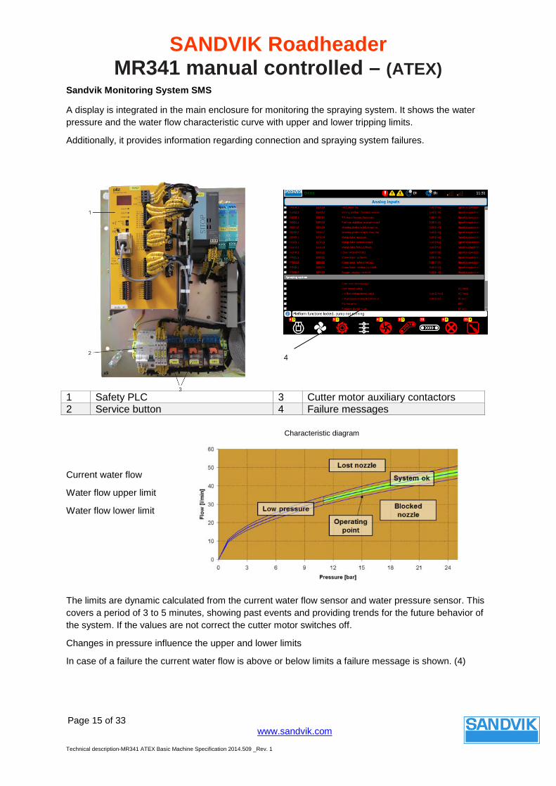
Sandvik Monitoring System SMS
A display is integrated in the main enclosure for monitoring the spraying system. It shows the water pressure and the water flow characteristic curve with upper and lower tripping limits.
Additionally, it provides information regarding connection and spraying system failures.
Current water flow
Water flow upper limit
Water flow lower limit
The limits are dynamic calculated from the current water flow sensor and water pressure sensor. This covers a period of 3 to 5 minutes, showing past events and providing trends for the future behavior of the system. If the values are not correct the cutter motor switches off.
Changes in pressure influence the upper and lower limits
In case of a failure the current water flow is above or below limits a failure message is shown. (4)
1 Safety PLC 3 Cutter motor auxiliary contactors 2 Service button 4 Failure messages
Characteristic diagram
4
SANDVIK Roadheader MR341 manual controlled – (ATEX)
Page 16 of 33
www.sandvik.com
Technical description-MR341 ATEX Basic Machine Specification 2014.509 _Rev. 1
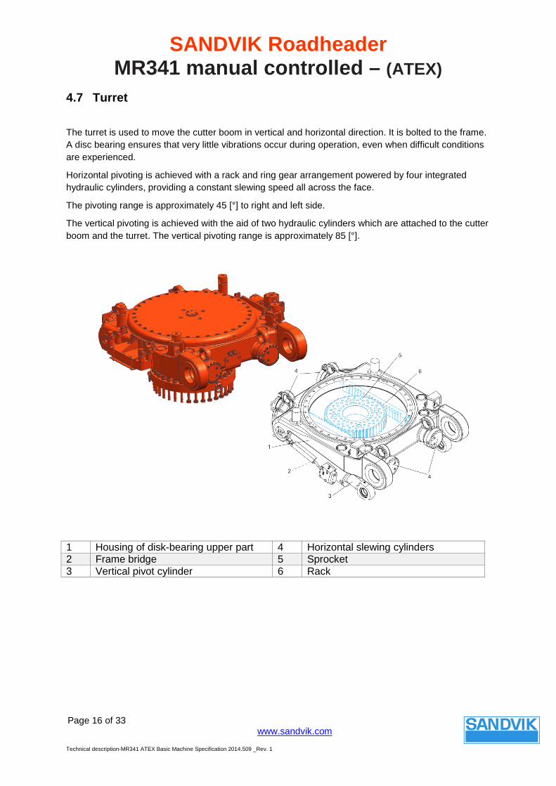
4.7 Turret
The turret is used to move the cutter boom in vertical and horizontal direction. It is bolted to the frame. A disc bearing ensures that very little vibrations occur during operation, even when difficult conditions are experienced.
Horizontal pivoting is achieved with a rack and ring gear arrangement powered by four integrated hydraulic cylinders, providing a constant slewing speed all across the face.
The pivoting range is approximately 45 [°] to right and left side.
The vertical pivoting is achieved with the aid of two hydraulic cylinders which are attached to the cutter boom and the turret. The vertical pivoting range is approximately 85 [°].
1 Housing of disk-bearing upper part 4 Horizontal slewing cylinders 2 Frame bridge 5 Sprocket 3 Vertical pivot cylinder 6 Rack
SANDVIK Roadheader MR341 manual controlled – (ATEX)
Page 17 of 33
www.sandvik.com
Technical description-MR341 ATEX Basic Machine Specification 2014.509 _Rev. 1
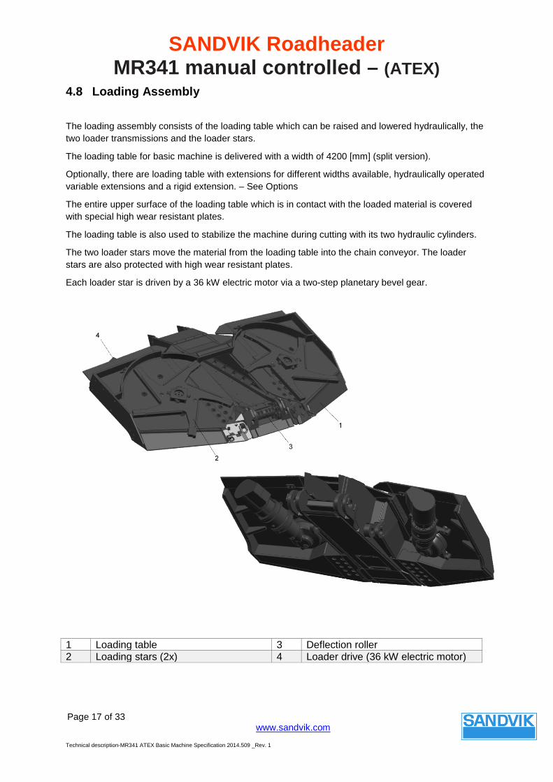
4.8 Loading Assembly
The loading assembly consists of the loading table which can be raised and lowered hydraulically, the two loader transmissions and the loader stars.
The loading table for basic machine is delivered with a width of 4200 [mm] (split version).
Optionally, there are loading table with extensions for different widths available, hydraulically operated variable extensions and a rigid extension. – See Options
The entire upper surface of the loading table which is in contact with the loaded material is covered with special high wear resistant plates.
The loading table is also used to stabilize the machine during cutting with its two hydraulic cylinders.
The two loader stars move the material from the loading table into the chain conveyor. The loader stars are also protected with high wear resistant plates.
Each loader star is driven by a 36 kW electric motor via a two-step planetary bevel gear.
1 Loading table 3 Deflection roller 2 Loading stars (2x) 4 Loader drive (36 kW electric motor)
SANDVIK Roadheader MR341 manual controlled – (ATEX)
Page 18 of 33
www.sandvik.com
Technical description-MR341 ATEX Basic Machine Specification 2014.509 _Rev. 1
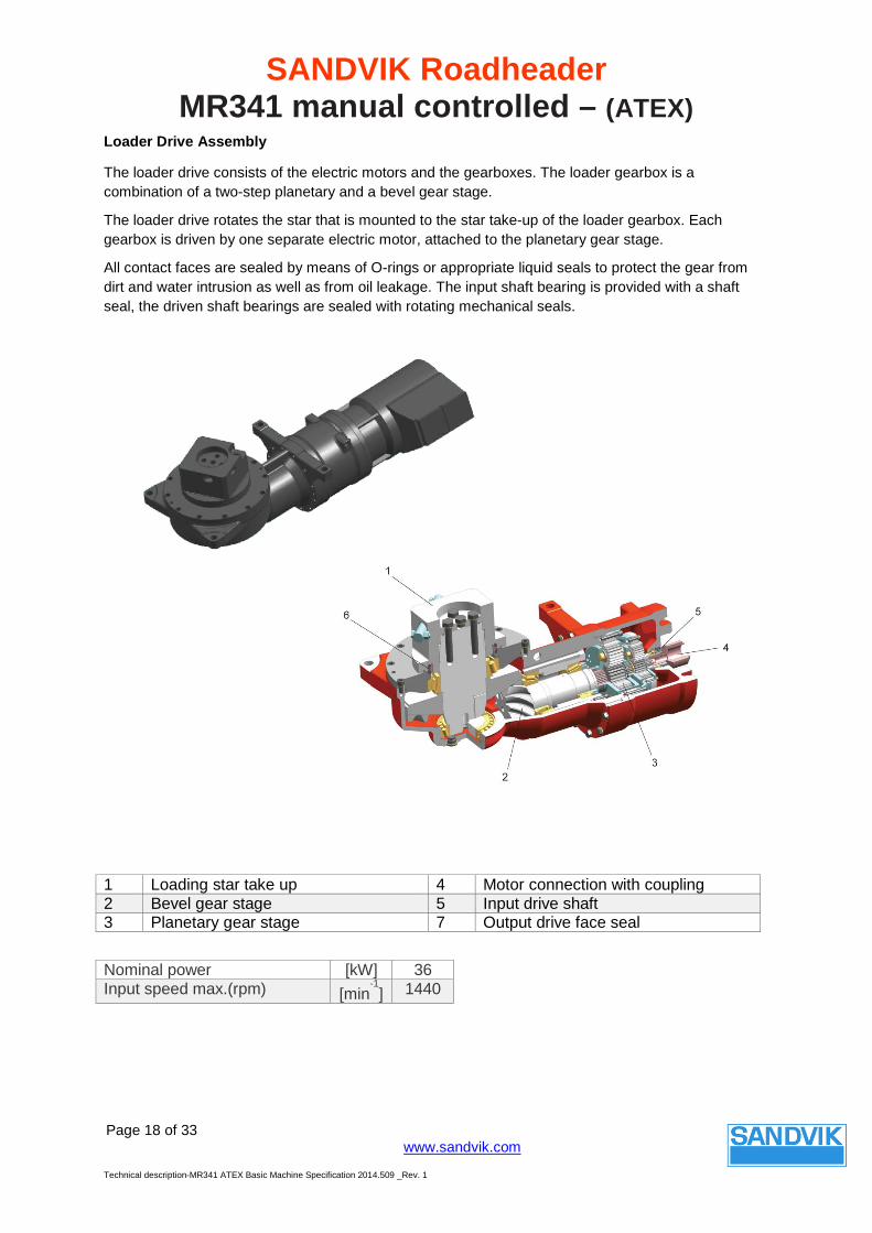
Loader Drive Assembly
The loader drive consists of the electric motors and the gearboxes. The loader gearbox is a combination of a two-step planetary and a bevel gear stage.
The loader drive rotates the star that is mounted to the star take-up of the loader gearbox. Each gearbox is driven by one separate electric motor, attached to the planetary gear stage.
All contact faces are sealed by means of O-rings or appropriate liquid seals to protect the gear from dirt and water intrusion as well as from oil leakage. The input shaft bearing is provided with a shaft seal, the driven shaft bearings are sealed with rotating mechanical seals.
Nominal power [kW] 36 Input speed max.(rpm) [min
-1] 1440
1 Loading star take up 4 Motor connection with coupling 2 Bevel gear stage 5 Input drive shaft 3 Planetary gear stage 7 Output drive face seal
SANDVIK Roadheader MR341 manual controlled – (ATEX)
Page 19 of 33
www.sandvik.com
Technical description-MR341 ATEX Basic Machine Specification 2014.509 _Rev. 1
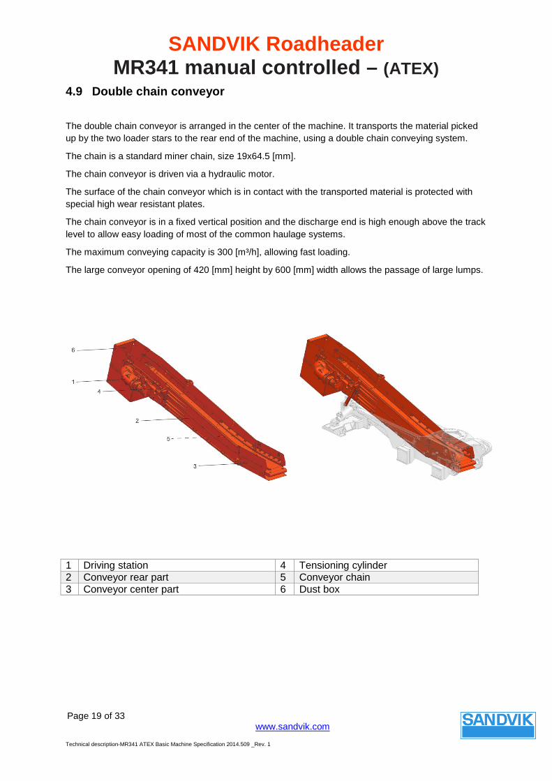
4.9 Double chain conveyor
The double chain conveyor is arranged in the center of the machine. It transports the material picked up by the two loader stars to the rear end of the machine, using a double chain conveying system.
The chain is a standard miner chain, size 19x64.5 [mm].
The chain conveyor is driven via a hydraulic motor.
The surface of the chain conveyor which is in contact with the transported material is protected with special high wear resistant plates.
The chain conveyor is in a fixed vertical position and the discharge end is high enough above the track level to allow easy loading of most of the common haulage systems.
The maximum conveying capacity is 300 [m³/h], allowing fast loading.
The large conveyor opening of 420 [mm] height by 600 [mm] width allows the passage of large lumps.
1 Driving station 4 Tensioning cylinder 2 Conveyor rear part 5 Conveyor chain 3 Conveyor center part 6 Dust box
SANDVIK Roadheader MR341 manual controlled – (ATEX)
Page 20 of 33
www.sandvik.com
Technical description-MR341 ATEX Basic Machine Specification 2014.509 _Rev. 1
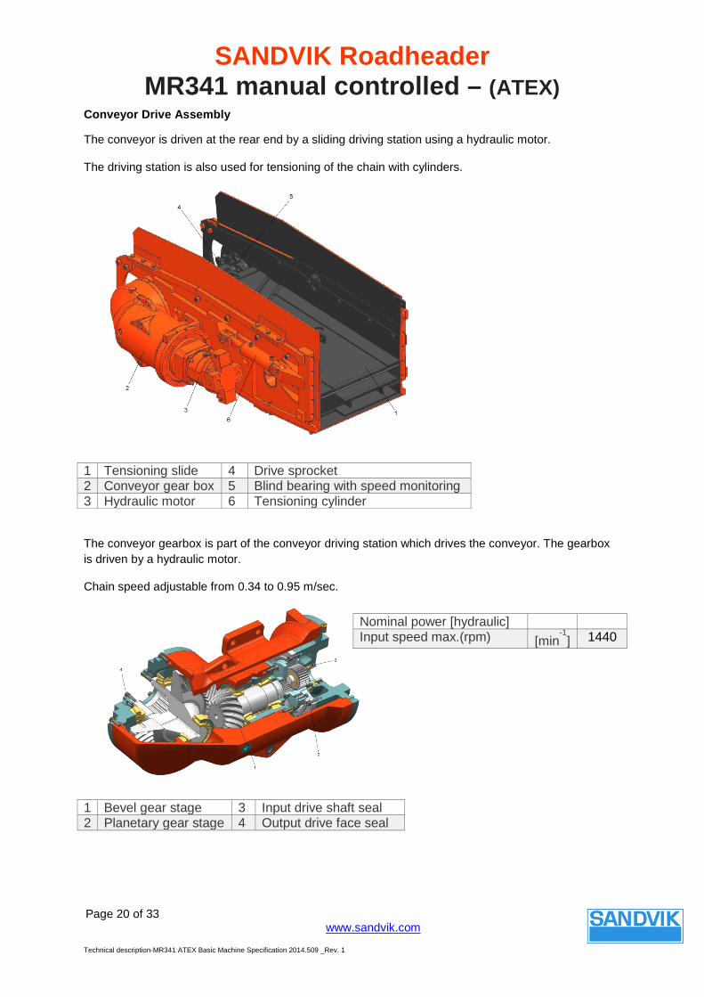
Conveyor Drive Assembly
The conveyor is driven at the rear end by a sliding driving station using a hydraulic motor.
The driving station is also used for tensioning of the chain with cylinders.
1 Tensioning slide 4 Drive sprocket 2 Conveyor gear box 5 Blind bearing with speed monitoring 3 Hydraulic motor 6 Tensioning cylinder
The conveyor gearbox is part of the conveyor driving station which drives the conveyor. The gearbox is driven by a hydraulic motor.
Chain speed adjustable from 0.34 to 0.95 m/sec.
1 Bevel gear stage 3 Input drive shaft seal 2 Planetary gear stage 4 Output drive face seal
Nominal power [hydraulic] Input speed max.(rpm) [min-1] 1440
SANDVIK Roadheader MR341 manual controlled – (ATEX)
Page 21 of 33
www.sandvik.com
Technical description-MR341 ATEX Basic Machine Specification 2014.509 _Rev. 1
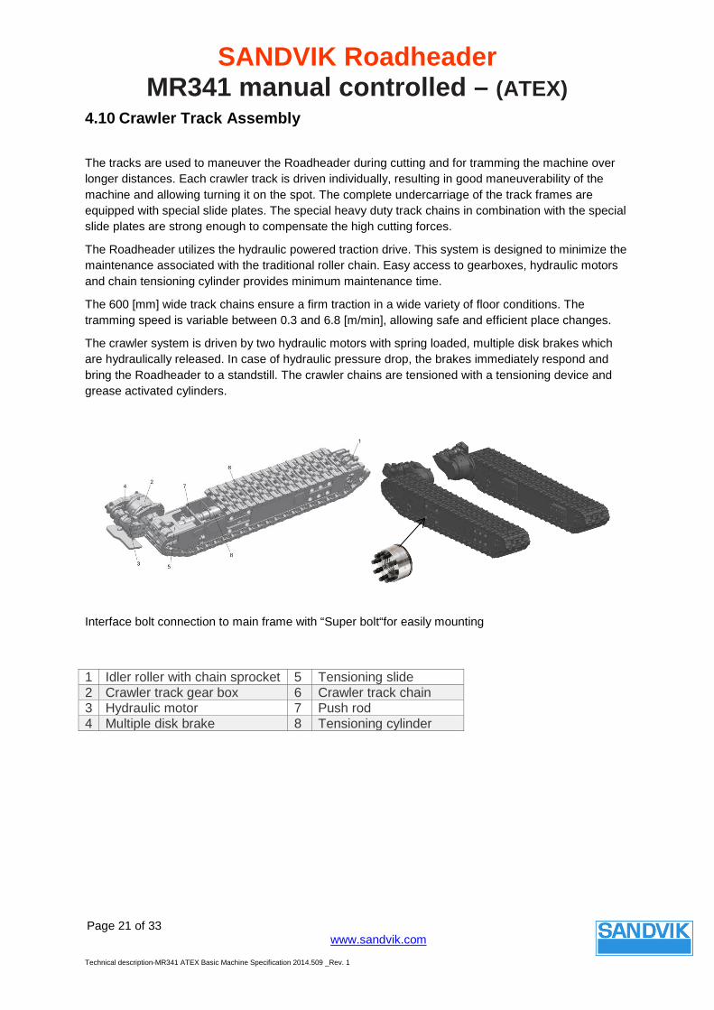
4.10 Crawler Track Assembly
The tracks are used to maneuver the Roadheader during cutting and for tramming the machine over longer distances. Each crawler track is driven individually, resulting in good maneuverability of the machine and allowing turning it on the spot. The complete undercarriage of the track frames are equipped with special slide plates. The special heavy duty track chains in combination with the special slide plates are strong enough to compensate the high cutting forces.
The Roadheader utilizes the hydraulic powered traction drive. This system is designed to minimize the maintenance associated with the traditional roller chain. Easy access to gearboxes, hydraulic motors and chain tensioning cylinder provides minimum maintenance time.
The 600 [mm] wide track chains ensure a firm traction in a wide variety of floor conditions. The tramming speed is variable between 0.3 and 6.8 [m/min], allowing safe and efficient place changes.
The crawler system is driven by two hydraulic motors with spring loaded, multiple disk brakes which are hydraulically released. In case of hydraulic pressure drop, the brakes immediately respond and bring the Roadheader to a standstill. The crawler chains are tensioned with a tensioning device and grease activated cylinders.
Interface bolt connection to main frame with “Super bolt“for easily mounting
1 Idler roller with chain sprocket 5 Tensioning slide 2 Crawler track gear box 6 Crawler track chain 3 Hydraulic motor 7 Push rod 4 Multiple disk brake 8 Tensioning cylinder
SANDVIK Roadheader MR341 manual controlled – (ATEX)
Page 22 of 33
www.sandvik.com
Technical description-MR341 ATEX Basic Machine Specification 2014.509 _Rev. 1
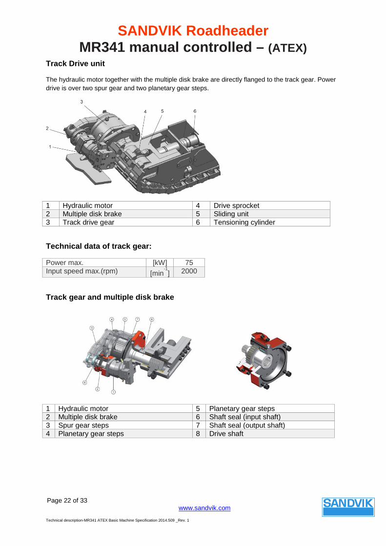
Track Drive unit
The hydraulic motor together with the multiple disk brake are directly flanged to the track gear. Power drive is over two spur gear and two planetary gear steps.
Technical data of track gear:
Power max. [kW] 75 Input speed max.(rpm) [min
-1] 2000
Track gear and multiple disk brake
1 Hydraulic motor 4 Drive sprocket 2 Multiple disk brake 5 Sliding unit 3 Track drive gear 6 Tensioning cylinder
1 Hydraulic motor 5 Planetary gear steps 2 Multiple disk brake 6 Shaft seal (input shaft) 3 Spur gear steps 7 Shaft seal (output shaft) 4 Planetary gear steps 8 Drive shaft
SANDVIK Roadheader MR341 manual controlled – (ATEX)
Page 23 of 33
www.sandvik.com
Technical description-MR341 ATEX Basic Machine Specification 2014.509 _Rev. 1
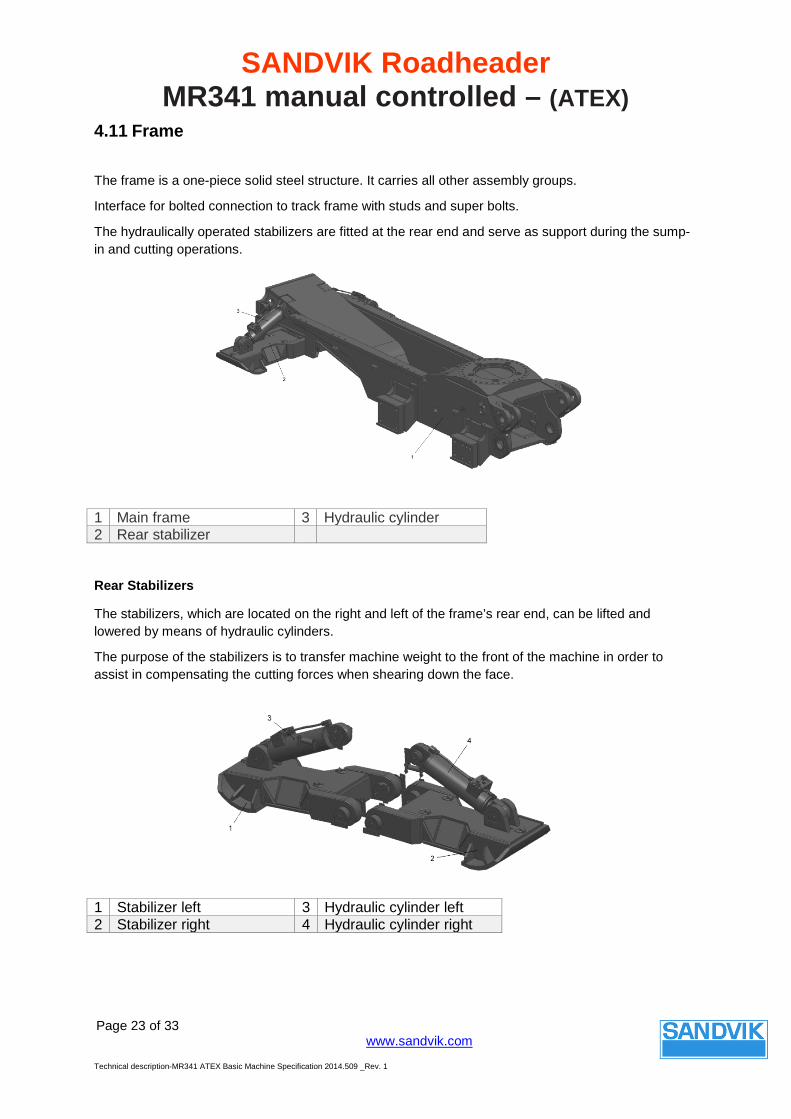
4.11 Frame
The frame is a one-piece solid steel structure. It carries all other assembly groups.
Interface for bolted connection to track frame with studs and super bolts.
The hydraulically operated stabilizers are fitted at the rear end and serve as support during the sump-in and cutting operations.
1 Main frame 3 Hydraulic cylinder 2 Rear stabilizer
Rear Stabilizers
The stabilizers, which are located on the right and left of the frame’s rear end, can be lifted and lowered by means of hydraulic cylinders.
The purpose of the stabilizers is to transfer machine weight to the front of the machine in order to assist in compensating the cutting forces when shearing down the face.
1 Stabilizer left 3 Hydraulic cylinder left 2 Stabilizer right 4 Hydraulic cylinder right
SANDVIK Roadheader MR341 manual controlled – (ATEX)
Page 24 of 33
www.sandvik.com
Technical description-MR341 ATEX Basic Machine Specification 2014.509 _Rev. 1
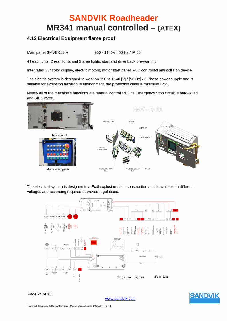
4.12 Electrical Equipment flame proof
Main panel SMVEX11-A 950 - 1140V / 50 Hz / IP 55
4 head lights, 2 rear lights and 3 area lights, start and drive back pre-warning
Integrated 15” color display, electric motors, motor start panel, PLC controlled anti collision device
The electric system is designed to work on 950 to 1140 [V] / [50 Hz] / 3 Phase power supply and is suitable for explosion hazardous environment, the protection class is minimum IP55.
Nearly all of the machine’s functions are manual controlled. The Emergency Stop circuit is hard-wired and SIL 2 rated.
The electrical system is designed in a Exdl explosion-state construction and is available in different voltages and according required approved regulations.
Main panel
Motor start panel
SANDVIK Roadheader MR341 manual controlled – (ATEX)
Page 25 of 33
www.sandvik.com
Technical description-MR341 ATEX Basic Machine Specification 2014.509 _Rev. 1
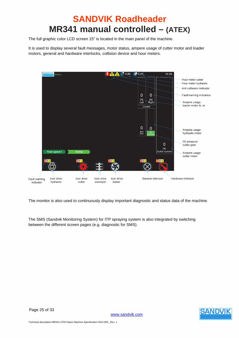
The full graphic color LCD screen 15” is located in the main panel of the machine.
It is used to display several fault messages, motor status, ampere usage of cutter motor and loader motors, general and hardware interlocks, collision device and hour meters.
The monitor is also used to continuously display important diagnostic and status data of the machine.
The SMS (Sandvik Monitoring System) for ITP spraying system is also integrated by switching between the different screen pages (e.g. diagnostic for SMS).
SANDVIK Roadheader MR341 manual controlled – (ATEX)
Page 26 of 33
www.sandvik.com
Technical description-MR341 ATEX Basic Machine Specification 2014.509 _Rev. 1
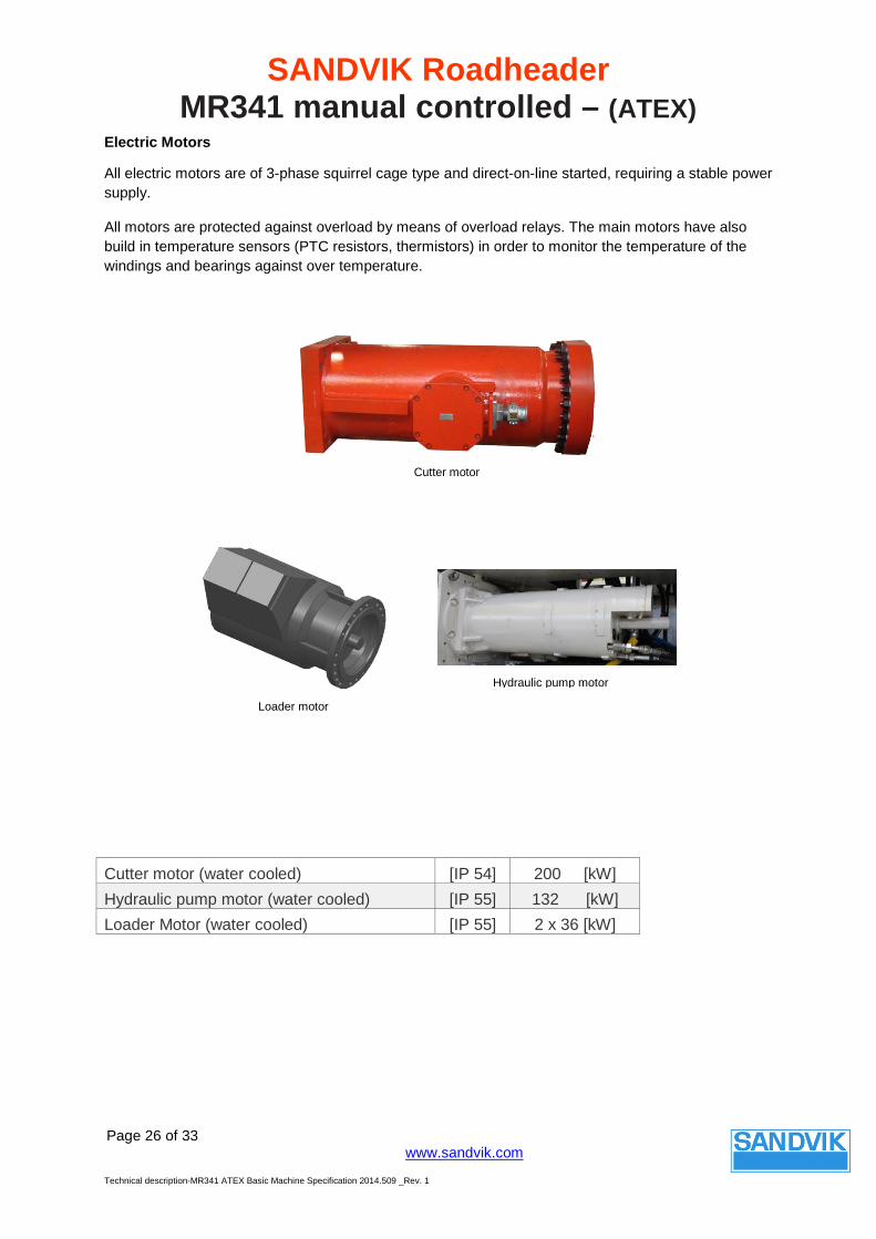
Electric Motors
All electric motors are of 3-phase squirrel cage type and direct-on-line started, requiring a stable power supply.
All motors are protected against overload by means of overload relays. The main motors have also build in temperature sensors (PTC resistors, thermistors) in order to monitor the temperature of the windings and bearings against over temperature.
Cutter motor (water cooled) [IP 54] 200 [kW] Hydraulic pump motor (water cooled) [IP 55] 132 [kW] Loader Motor (water cooled) [IP 55] 2 x 36 [kW]
Hydraulic pump motor
Cutter motor
Loader motor
SANDVIK Roadheader MR341 manual controlled – (ATEX)
Page 27 of 33
www.sandvik.com
Technical description-MR341 ATEX Basic Machine Specification 2014.509 _Rev. 1
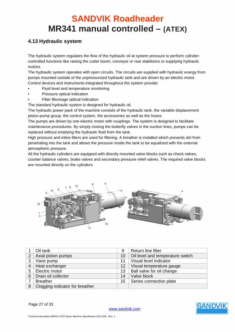
4.13 Hydraulic system
The hydraulic system regulates the flow of the hydraulic oil at system pressure to perform cylinder-controlled functions like raising the cutter boom, conveyor or rear stabilizers or supplying hydraulic motors. The hydraulic system operates with open circuits. The circuits are supplied with hydraulic energy from pumps mounted outside of the unpressurized hydraulic tank and are driven by an electric motor. Control devices and instruments integrated throughout the system provide: • Fluid level and temperature monitoring • Pressure optical indication • Filter Blockage optical indication The standard hydraulic system is designed for hydraulic oil. The hydraulic power pack of the machine consists of the hydraulic tank, the variable displacement piston-pump group, the control system, the accessories as well as the hoses. The pumps are driven by one electric motor with couplings. The system is designed to facilitate maintenance procedures. By simply closing the butterfly valves in the suction lines, pumps can be replaced without emptying the hydraulic fluid from the tank. High pressure and inline filters are used for filtering. A breather is installed which prevents dirt from penetrating into the tank and allows the pressure inside the tank to be equalized with the external atmospheric pressure. All the hydraulic cylinders are equipped with directly mounted valve blocks such as check valves, counter balance valves, brake valves and secondary pressure relief valves. The required valve blocks are mounted directly on the cylinders.
1 Oil tank 9 Return line filter 2 Axial piston pumps 10 Oil level and temperature switch 3 Vane pump 11 Visual level indicator 4 Heat exchanger 12 Visual temperature gauge 5 Electric motor 13 Ball valve for oil change 6 Drain oil collector 14 Valve block 7 Breather 15 Series connection plate 8 Clogging indicator for breather
SANDVIK Roadheader MR341 manual controlled – (ATEX)
Page 28 of 33
www.sandvik.com
Technical description-MR341 ATEX Basic Machine Specification 2014.509 _Rev. 1
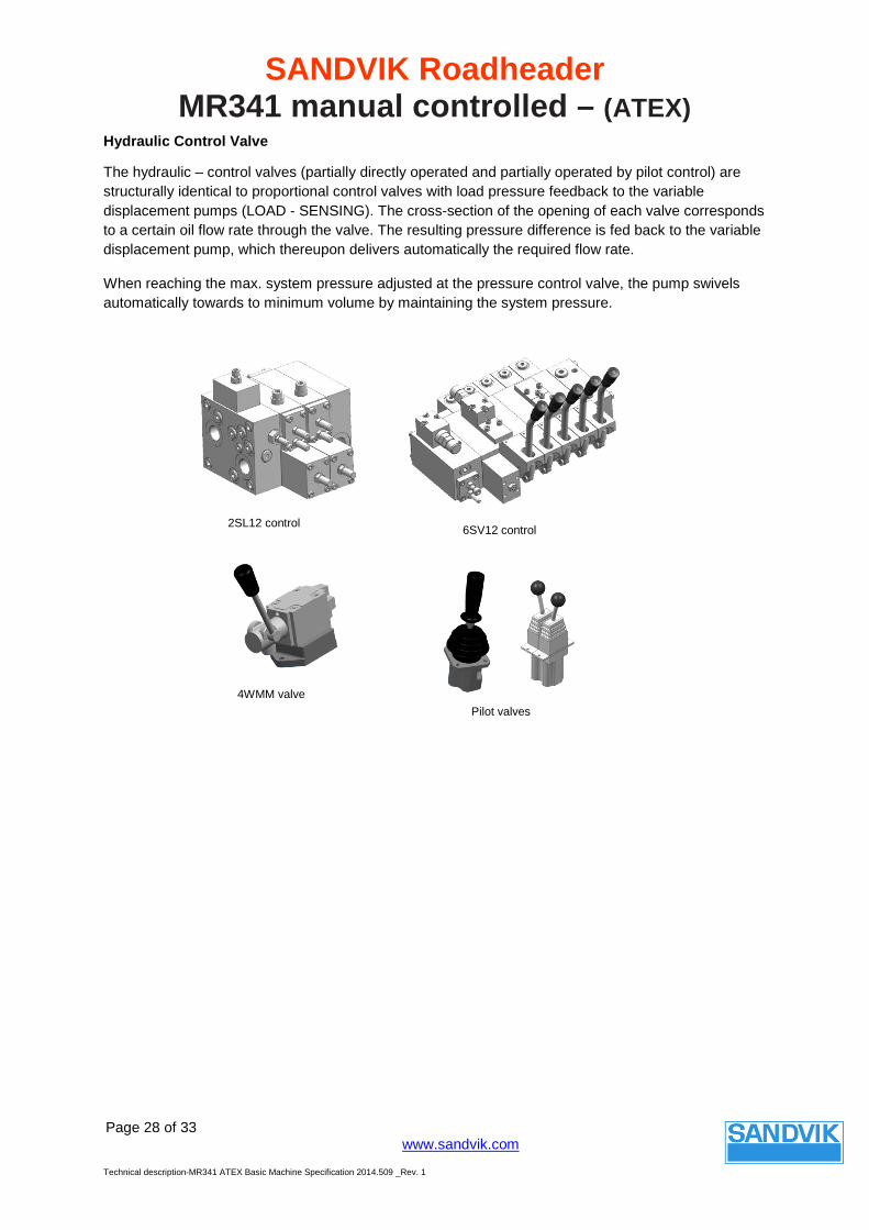
Hydraulic Control Valve
The hydraulic – control valves (partially directly operated and partially operated by pilot control) are structurally identical to proportional control valves with load pressure feedback to the variable displacement pumps (LOAD - SENSING). The cross-section of the opening of each valve corresponds to a certain oil flow rate through the valve. The resulting pressure difference is fed back to the variable displacement pump, which thereupon delivers automatically the required flow rate.
When reaching the max. system pressure adjusted at the pressure control valve, the pump swivels automatically towards to minimum volume by maintaining the system pressure.
2SL12 control 6SV12 control
4WMM valve Pilot valves
SANDVIK Roadheader MR341 manual controlled – (ATEX)
Page 29 of 33
www.sandvik.com
Technical description-MR341 ATEX Basic Machine Specification 2014.509 _Rev. 1
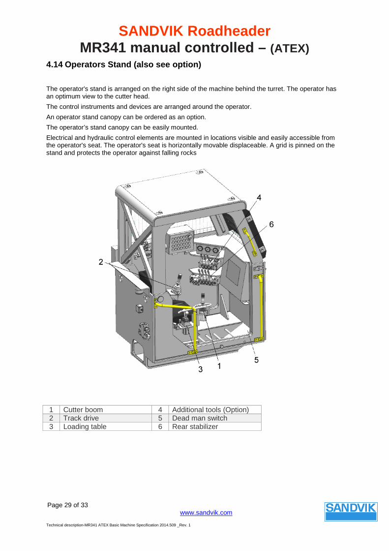
4.14 Operators Stand (also see option)
The operator's stand is arranged on the right side of the machine behind the turret. The operator has an optimum view to the cutter head. The control instruments and devices are arranged around the operator. An operator stand canopy can be ordered as an option. The operator’s stand canopy can be easily mounted. Electrical and hydraulic control elements are mounted in locations visible and easily accessible from the operator's seat. The operator's seat is horizontally movable displaceable. A grid is pinned on the stand and protects the operator against falling rocks
1 Cutter boom 4 Additional tools (Option) 2 Track drive 5 Dead man switch 3 Loading table 6 Rear stabilizer
SANDVIK Roadheader MR341 manual controlled – (ATEX)
Page 30 of 33
www.sandvik.com
Technical description-MR341 ATEX Basic Machine Specification 2014.509 _Rev. 1
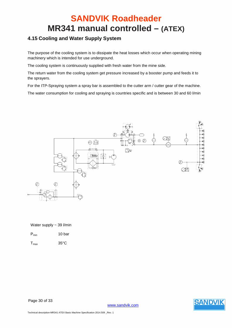
Water supply ~ 39 l/min
Pmin 10 bar
Tmax 35°C
4.15 Cooling and Water Supply System
The purpose of the cooling system is to dissipate the heat losses which occur when operating mining machinery which is intended for use underground.
The cooling system is continuously supplied with fresh water from the mine side.
The return water from the cooling system get pressure increased by a booster pump and feeds it to the sprayers.
For the ITP-Spraying system a spray bar is assembled to the cutter arm / cutter gear of the machine.
The water consumption for cooling and spraying is countries specific and is between 30 and 60 l/min
SANDVIK Roadheader MR341 manual controlled – (ATEX)
Page 31 of 33
www.sandvik.com
Technical description-MR341 ATEX Basic Machine Specification 2014.509 _Rev. 1
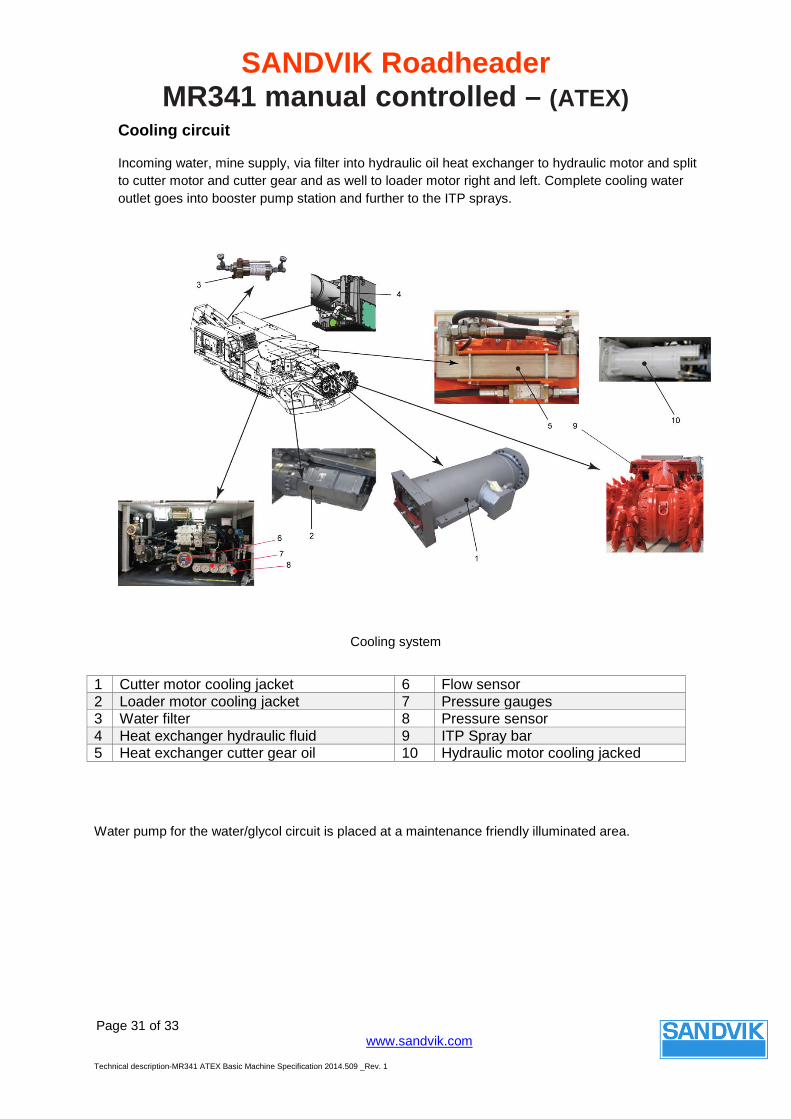
Cooling circuit
Incoming water, mine supply, via filter into hydraulic oil heat exchanger to hydraulic motor and split to cutter motor and cutter gear and as well to loader motor right and left. Complete cooling water outlet goes into booster pump station and further to the ITP sprays.
Cooling system
Water pump for the water/glycol circuit is placed at a maintenance friendly illuminated area.
1 Cutter motor cooling jacket 6 Flow sensor 2 Loader motor cooling jacket 7 Pressure gauges 3 Water filter 8 Pressure sensor 4 Heat exchanger hydraulic fluid 9 ITP Spray bar 5 Heat exchanger cutter gear oil 10 Hydraulic motor cooling jacked

SANDVIK Roadheader MR341 manual controlled – (ATEX)
Page 32 of 33
www.sandvik.com
Technical description-MR341 ATEX Basic Machine Specification 2014.509 _Rev. 1
4.16 Lubrication System
The Roadheader is equipped with one hydraulic driven multi-line lubrication pump, powered from the hydraulic and mounted on the turret.
The multi-line lubrication pumps accommodate pump elements and lubricating points. The delivery volume of each element is infinitely variable within a certain range. Grease is continuously supplied to the connected lubricating points.
Some elements are not lubricated via the central lubrication system but must be manually greased by means of some individual grease points and lubrication manifolds. The lubrication strips act as a central distributor to reach points which are difficult to access or which are located in one of the machine’s danger areas.
Grease filling at the lubrication pump used for automatic greasing is very service friendly.
Grease can either filled by using a cartridge or filled manually by the use of a grease pump (air compressed driven) into the grease tank of the lubrication pump.
Grease pump
Grease bar loading table
Grease bar rear stabilizer
SANDVIK Roadheader MR341 manual controlled – (ATEX)
Page 33 of 33
www.sandvik.com
Technical description-MR341 ATEX Basic Machine Specification 2014.509 _Rev. 1
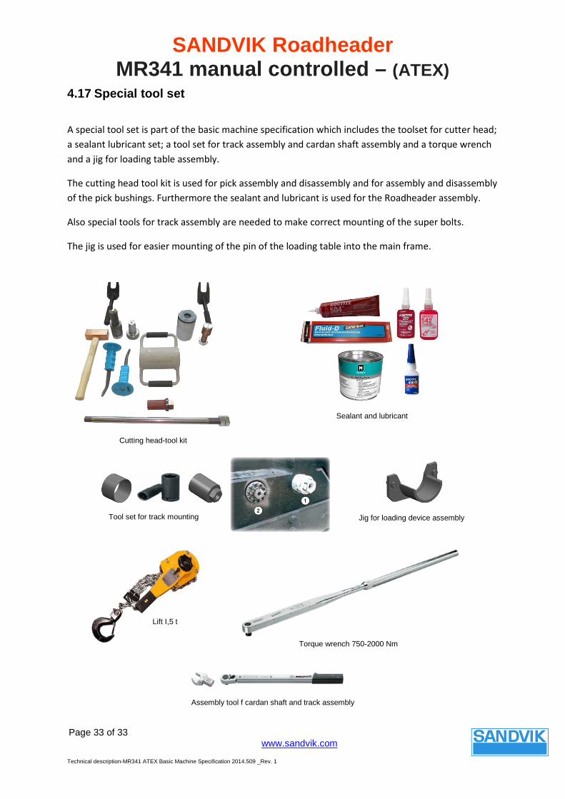
4.17 Special tool set
A special tool set is part of the basic machine specification which includes the toolset for cutter head; a sealant lubricant set; a tool set for track assembly and cardan shaft assembly and a torque wrench and a jig for loading table assembly.
The cutting head tool kit is used for pick assembly and disassembly and for assembly and disassembly of the pick bushings. Furthermore the sealant and lubricant is used for the Roadheader assembly.
Also special tools for track assembly are needed to make correct mounting of the super bolts.
The jig is used for easier mounting of the pin of the loading table into the main frame.
Cutting head-tool kit
Sealant and lubricant
Lift I,5 t
Torque wrench 750-2000 Nm
Assembly tool f cardan shaft and track assembly
Tool set for track mounting Jig for loading device assembly