Embed Size (px)
Citation preview
1
VF22PRO
[email protected] more information call 1800 255 349 | WWW.ALLFASTENERS.COM.AU
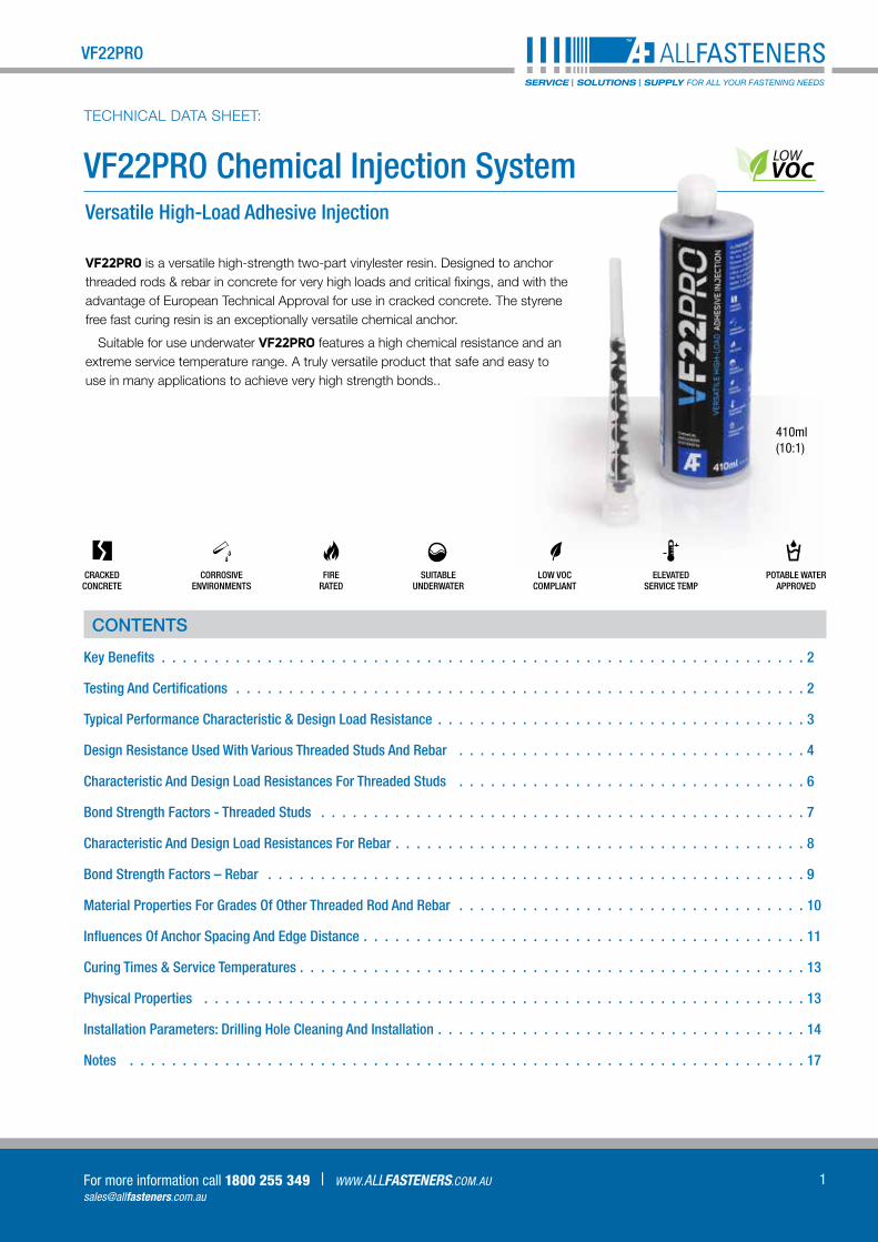
VF22PRO Chemical Injection SystemVersatile High-Load Adhesive Injection
TECHNICAL DATA SHEET:
VF22PRO is a versatile high-strength two-part vinylester resin. Designed to anchor threaded rods & rebar in concrete for very high loads and critical fixings, and with the advantage of European Technical Approval for use in cracked concrete. The styrene free fast curing resin is an exceptionally versatile chemical anchor.
Suitable for use underwater VF22PRO features a high chemical resistance and an extreme service temperature range. A truly versatile product that safe and easy to use in many applications to achieve very high strength bonds..
410ml(10:1)
CONTENTS
Key Benefits 2
Testing And Certifications 2
Typical Performance Characteristic & Design Load Resistance 3
Design Resistance Used With Various Threaded Studs And Rebar 4
Characteristic And Design Load Resistances For Threaded Studs 6
Bond Strength Factors - Threaded Studs 7
Characteristic And Design Load Resistances For Rebar 8
Bond Strength Factors – Rebar 9
Material Properties For Grades Of Other Threaded Rod And Rebar 10
Influences Of Anchor Spacing And Edge Distance 11
Curing Times & Service Temperatures 13
Physical Properties 13
Installation Parameters: Drilling Hole Cleaning And Installation 14
Notes 17
CRACKED CONCRETE
Kn
CORROSIVE ENVIRONMENTS Kn
SUITABLE UNDERWATER
Kn
LOW VOCCOMPLIANT
Kn
FIRE RATED
Kn
Kn
POTABLE WATERAPPROVED
Kn
ELEVATED SERVICE TEMP
LOWVOC

2
VF22PRO Chemical Injection SystemTECHNICAL DATA SHEET:
MELBOURNE 03 9330 0555 78 Logistics Street, Keilor Park VIC 3042 | SYDNEY 02 8844 4550 | ADELAIDE 08 8359 8805
V1-0
9201
6-R2
KEY BENEFITS
§§ ETA approved for use in cracked and non-cracked concrete
§§ Suitable for use underwater and in corrosive environments
§§ A+ VOC Content Rating / LEED compliant
§§ Fire rating approved
§§ High chemical resistance and ideal for use in areas of elevated service temperatures
§§ Use with all grades of threaded studs and post-installed rebar
§§ Contact with potable water
Approvals
TESTING AND CERTIFICATIONS
§§ ETA 15/0236 ETAG 01-05 Option 1: M12 - M16 For use in Cracked Concrete
§§ ETA 15/0236 ETAG 01-05 Option 7: M8 - M24 / rebar Ø 8 to 25mm For use in Non-cracked Concrete
§§ VF22PRO complies to NCC & SA TS 101:2015
§§ Approved in flooded holes, wet and dry holes
§§ Tested to BS6920 for use with potable water. WRAS certificate 1501538
§§ R240 Fire Test report
§§ Tested according to LEED 2009 EQ c4.1, SCAQMD rule 1168 (2005).
BS6920-1:2000 Please refer to the WRAS certificate 1501538 for the approval parameters.
FIRE RATED
Information on the emission of volatile substances (VOC) in indoor air, with a risk of inhalation toxicity, on a scale ranging from class A + (very low emissions) to C (high emissions) level. LEED Compliant.
Water Regulations Advisory Scheme Ltd.
Unit 13,
Willow Road,
Pen y Fan Industrial Estate,
Crumlin,
Gwent,
NP11 4EG
5311
Approval Number: 1501538
Test Report: MAT/LAB 764H
30th March 2015
Allfasteners Pty. Ltd.
78 - 84 Logistics Street,
Keilor Park,
VIC 3042,
PO Box 1025,
Tullamarine,
Australia
WATER REGULATIONS ADVISORY SCHEME LTD. (WRAS)
MATERIAL APPROVAL
The material referred to in this letter is suitable for contact with wholesome water for domestic purposes having met the
requirements of BS6920-1:2000 and/or 2014 ‘Suitability of non-metallic products for use in contact with water intended
for human consumption with regard to their effect on the quality of the water’.
The reference relates solely to its effect on the quality of the water with which it may come into contact and does not
signify the approval of its mechanical or physical properties for any use.
RESIN ANCHORS
VF22PRO. Site applied, grey coloured vinyl ester resin intended for use as a resin anchor. Apply as per manufacturer's
instructions version '05/07/2014'. Cure for 7days@7°C. For use with water up to 23°C. For use only as a resin anchor
having been tested at a reduced surface area to volume ratio of 1,000mm² per 1 litre of water. This material is only
approved for the curing conditions that appear on the approval. If the cure conditions are varied from those specified on
the approval then the material is not covered by the scope of the approval.
APPROVAL NUMBER: 1501538
APPROVAL HOLDER: ALLFASTENERS PTY. LTD.
The Scheme reserves the right to review approval.
Approval 1501538 is valid between January 2015 and January 2020
An entry, as above, will accordingly be included in the Water Fittings Directory on-line under the section headed,
“Materials which have passed full tests of effect on water quality”.
The Directory may be found at: www.wras.co.uk/directory
Yours faithfully
Jason Furnival
Approvals & Enquiries Manager
Water Regulations Advisory Scheme
The Water Regulations Advisory Scheme Ltd. Registered in England No, 06663930 Registered office: 13 Newby Road, Hazel Grove, Stockport, Cheshire, SK7 5DA
Tel:+44(0)333 207 9030 Fax:+44(0)1495 248 540 Email:[email protected] website:www.wras.co.uk
ETA XX/XXXXETAG 01-01 TR 023
Post-installed Rebar Ø 8 to 16mm
ALLFASTENERS Pty Ltd14
VF22PRO
XXXX
ETA 15/0236ETAG 01-05 Option 7
M8 - M24 / rebar Ø 8 to 25mm
For use in Non-Cracked Concrete
ALLFASTENERS Pty Ltd12
0679-CPR-1040VF22PRO
XXXX
ETA 15/0236ETAG 01-05 Option 1
M12 - M16 threaded bar
ALLFASTENERS Pty Ltd12
0679-CPR-1040VF22PRO
For use in Cracked Concrete
XXXX
LOWVOC
410ml Co-axial Cartridge
(10:1)
3
VF22PRO
[email protected] more information call 1800 255 349 | WWW.ALLFASTENERS.COM.AU
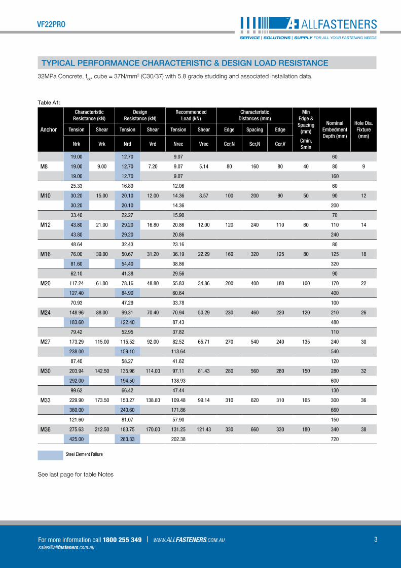
Table A1:
Anchor
Characteristic Resistance (kN)
Design Resistance (kN)
Recommended Load (kN)
Characteristic Distances (mm)
Min Edge & Spacing
(mm)
Nominal EmbedmentDepth (mm)
Hole Dia Fixture(mm)
Tension Shear Tension Shear Tension Shear Edge Spacing Edge
Nrk Vrk Nrd Vrd Nrec Vrec Ccr,N Scr,N Ccr,VCmin, Smin
19.00 12.70 9.07 60
M8 19.00 9.00 12.70 7.20 9.07 5.14 80 160 80 40 80 9
19.00 12.70 9.07 160
25.33 16.89 12.06 60
M10 30.20 15.00 20.10 12.00 14.36 8.57 100 200 90 50 90 12
30.20 20.10 14.36 200
33.40 22.27 15.90 70
M12 43.80 21.00 29.20 16.80 20.86 12.00 120 240 110 60 110 14
43.80 29.20 20.86 240
48.64 32.43 23.16 80
M16 76.00 39.00 50.67 31.20 36.19 22.29 160 320 125 80 125 18
81.60 54.40 38.86 320
62.10 41.38 29.56 90
M20 117.24 61.00 78.16 48.80 55.83 34.86 200 400 180 100 170 22
127.40 84.90 60.64 400
70.93 47.29 33.78 100
M24 148.96 88.00 99.31 70.40 70.94 50.29 230 460 220 120 210 26
183.60 122.40 87.43 480
79.42 52.95 37.82 110
M27 173.29 115.00 115.52 92.00 82.52 65.71 270 540 240 135 240 30
238.00 159.10 113.64 540
87.40 58.27 41.62 120
M30 203.94 142.50 135.96 114.00 97.11 81.43 280 560 280 150 280 32
292.00 194.50 138.93 600
99.62 66.42 47.44 130
M33 229.90 173.50 153.27 138.80 109.48 99.14 310 620 310 165 300 36
360.00 240.60 171.86 660
121.60 81.07 57.90 150
M36 275.63 212.50 183.75 170.00 131.25 121.43 330 660 330 180 340 38
425.00 283.33 202.38 720
Steel Element Failure
See last page for table Notes
TYPICAL PERFORMANCE CHARACTERISTIC & DESIGN LOAD RESISTANCE
32MPa Concrete, fck, cube = 37N/mm2 (C30/37) with 5.8 grade studding and associated installation data.
4
VF22PRO Chemical Injection SystemTECHNICAL DATA SHEET:
MELBOURNE 03 9330 0555 78 Logistics Street, Keilor Park VIC 3042 | SYDNEY 02 8844 4550 | ADELAIDE 08 8359 8805
V1-0
9201
6-R2
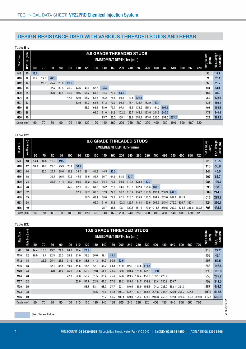
Table B1:
Stud
Siz
e
Hole
Dia
(m
m) 5.8 GRADE THREADED STUDS
hef,
Failu
re
(mm
)
Fd,s
, Des
ign
Lo
ad (k
N)
EMBEDMENT DEPTH, hef (mm)
60 70 80 90 100 110 120 130 140 160 200 240 280 320 400 480 540 600 660 720
M8 10 12.7 53 12 7
M10 12 16.9 19.7 20.1 71 20 1
M12 14 22.2 25.4 28.6 29.2 92 29 2
M16 18 32.4 36.5 40.5 44.6 48.6 52.7 54.4 134 54 4
M20 24 36.8 41.4 46.0 50.6 55.2 59.8 64.4 73.6 84.9 185 84 9
M24 28 47.3 52.0 56.7 61.5 66.2 75.6 94.6 113.5 122.4 259 122 4
M27 32 52.9 57.7 62.5 67.3 77.0 96.2 115.4 134.7 153.9 159.1 331 159 1
M30 35 58.3 63.1 68.0 77.7 97.1 116.5 135.9 155.3 194.2 194.5 401 194 5
M33 38 66.5 71.6 81.8 102.2 122.7 143.1 163.6 204.5 240.6 471 240 6
M36 40 75.7 86.5 108.1 129.8 151.4 173.0 216.3 259.5 283.2 524 283 2
Depth (mm) 60 70 80 90 100 110 120 130 140 160 200 240 280 320 400 480 540 600 660 720
Table B2:
Stud
Siz
e
Hole
Dia
(m
m) 8.8 GRADE THREADED STUDS
hef,
Failu
re
(mm
)
Fd,s
, Des
ign
Lo
ad (k
N)
EMBEDMENT DEPTH, hef (mm)
60 70 80 90 100 110 120 130 140 160 200 240 280 320 400 480 540 600 660 720
M8 10 14.4 16.8 19.2 19.5 81 19 5
M10 12 16.9 19.7 22.5 25.3 28.2 30.9 110 30 9
M12 14 22.2 25.4 28.6 31.8 35.0 38.1 41.3 44.5 45.0 141 45 0
M16 18 32.4 36.5 40.5 44.6 48.6 52.7 56.7 64.8 81.0 83.7 207 83 7
M20 24 36.8 41.4 46.0 50.6 55.2 59.8 64.4 73.6 92.0 110.4 128.8 130.7 284 130 7
M24 28 47.3 52.0 56.7 61.5 66.2 75.6 94.6 113.5 132.4 151.3 188.3 398 188 3
M27 32 52.9 57.7 62.5 67.3 77.0 96.2 115.4 134.7 153.9 192.4 230.9 244.8 509 244 8
M30 35 58.3 63.1 68.0 77.7 97.1 116.5 135.9 155.3 194.2 233.0 262.1 291.3 616 299 2
M33 38 66.5 71.6 81.8 102.2 122.7 143.1 163.6 204.5 245.4 276.0 306.7 337.4 724 370 1
M36 40 75.7 86.5 108.1 129.8 151.4 173.0 216.3 259.5 292.0 324.4 356.8 389.3 806 435 7
Depth (mm) 60 70 80 90 100 110 120 130 140 160 200 240 280 320 400 480 540 600 660 720
Table B3:
Stud
Siz
e
Hole
Dia
(m
m) 10.9 GRADE THREADED STUDS
hef,
Failu
re
(mm
)
Fd,s
, Des
ign
Lo
ad (k
N)
EMBEDMENT DEPTH, hef (mm)
60 70 80 90 100 110 120 130 140 160 200 240 280 320 400 480 540 600 660 720
M8 10 14.4 16.8 19.2 21.6 24.0 26.4 27.2 113 27 2
M10 12 16.9 19.7 22.5 25.3 28.2 31.0 33.8 36.6 39.4 43.1 153 43 1
M12 14 22.2 25.4 28.6 31.8 35.0 38.1 41.3 44.5 50.9 62.6 197 62 6
M16 18 32.4 36.5 40.5 44.6 48.6 52.7 56.7 64.8 81.0 97.2 113.5 116.6 288 116 6
M20 24 36.8 41.4 46.0 50.6 55.2 59.8 64.4 73.6 92.0 110.4 128.8 147.2 182.0 396 182 0
M24 28 47.3 52.0 56.7 61.5 66.2 75.6 94.6 113.5 132.4 151.3 189.1 226.9 555 262 2
M27 32 52.9 57.7 62.5 67.3 77.0 96.2 115.4 134.7 153.9 192.4 230.9 259.7 709 341 0
M30 35 58.3 63.1 68.0 77.7 97.1 116.5 135.9 155.3 194.2 233.0 262.1 291.3 858 416 7
M33 38 66.5 71.6 81.8 102.2 122.7 143.1 163.6 204.5 245.4 276.0 306.7 337.4 1009 515 5
M36 40 75.7 86.5 108.1 129.8 151.4 173.0 216.3 259.5 292.0 324.4 356.8 389.3 1123 606 9
Depth (mm) 60 70 80 90 100 110 120 130 140 160 200 240 280 320 400 480 540 600 660 720
DESIGN RESISTANCE USED WITH VARIOUS THREADED STUDS AND REBAR
Steel Element Failure

5
VF22PRO
[email protected] more information call 1800 255 349 | WWW.ALLFASTENERS.COM.AU
Table B6:
Bar D
ia (
mm
)
Hole
Dia
(m
m) HIGH BOND REINFORCING BARS Fyk = 500N/mm2
hef,
Failu
re
(mm
)
Fd,s
, Des
ign
Lo
ad (k
N)EMBEDMENT DEPTH, hef (mm)
60 70 80 90 100 110 120 130 140 160 200 240 280 320 400 500 560 640 720 800
8 10 9.8 11.4 13.1 14.7 16.3 18.0 19.6 21.2 21.9 134 21 9
10 12 11.6 13.5 15.5 17.4 19.4 21.3 23.2 25.2 27.1 31.0 34.1 176 34 1
12 15 15.4 17.6 19.7 21.9 24.1 26.3 28.5 30.7 35.1 43.9 49.2 224 49 2
16 18 21.6 24.3 27.0 29.8 32.5 35.2 37.9 43.3 54.1 64.9 75.7 86.5 323 87 4
20 25 23.6 26.8 29.5 32.5 35.4 38.4 41.8 47.3 59.1 70.9 82.7 94.5 118.1 539 136 6
25 30 31.7 34.8 38.0 41.2 44.3 50.6 63.3 76.0 88.6 101.3 126.6 158.3 621 196 5
28 35 37.4 40.8 44.1 47.5 54.3 67.9 81.5 95.1 108.7 135.8 169.8 190.2 789 267 8
32 40 48.4 52.1 59.5 74.4 89.3 104.2 119.0 148.8 186.0 208.3 238.1 940 349 7
36 44 58.6 67.0 83.7 100.4 117.2 133.9 167.4 209.3 234.4 267.8 301.3 1060 443 5
40 50 74.4 93.0 111.6 130.2 148.8 186.0 232.5 260.4 297.6 334.8 372.0 1175 546 3
Depth (mm) 60 70 80 90 100 110 120 130 140 160 200 240 280 320 400 500 560 640 720 800
Table B4:
Stud
Siz
e
Hole
Dia
(m
m) A4-70 STAINLESS STEEL STUDS
hef,
Failu
re
(mm
)
Fd,s
, Des
ign
Lo
ad (k
N)
EMBEDMENT DEPTH, hef (mm)
60 70 80 90 100 110 120 130 140 160 200 240 280 320 400 480 540 600 660 720
M8 10 13.7 57 13 7
M10 12 16.9 19.7 21.7 77 21 7
M12 14 22.2 25.4 28.6 31.6 99 31 6
M16 18 32.4 36.5 40.5 44.6 48.6 52.7 56.7 58.8 145 58 8
M20 24 36.8 41.4 46.0 50.6 55.2 59.8 64.4 73.6 91.7 199 91 7
M24 28 47.3 52.0 56.7 61.5 66.2 75.6 94.6 113.5 132.1 279 132 1
M27 32 52.9 57.7 62.5 67.3 77.0 80.2 167 80 2
M30 35 58.3 63.1 68.0 77.7 97.1 98.1 202 98 1
M33 38 66.5 71.6 81.8 102.2 121.3 237 121 3
M36 40 75.7 86.5 108.1 129.8 142.8 264 142 8
Depth (mm) 60 70 80 90 100 110 120 130 140 160 200 240 280 320 400 480 540 600 660 720
Table B5:
Stud
Siz
e
Hole
Dia
(m
m) A4-80 STAINLESS STEEL STUDS
hef,
Failu
re
(mm
)
Fd,s
, Des
ign
Lo
ad (k
N)
EMBEDMENT DEPTH, hef (mm)
60 70 80 90 100 110 120 130 140 160 200 240 280 320 400 480 540 600 660 720
M8 10 14.4 15.7 65 15 7
M10 12 19.7 22.5 24.8 88 24 8
M12 14 22.2 25.4 28.6 31.8 35.0 36.1 113 36 1
M16 18 32.4 36.5 40.5 44.6 48.6 52.7 56.7 64.8 67.2 166 67 2
M20 24 36.8 41.4 46.0 50.6 55.2 59.8 64.4 73.6 92.0 104.8 226 104 8
M24 28 47.3 52.0 56.7 61.5 66.2 75.6 94.6 113.5 132.1 279 132 1
M27 32 52.9 57.7 62.5 67.3 77.0 80.2 167 80 2
M30 35 58.3 63.1 68.0 77.7 97.1 98.1 202 98 1
M33 38 66.5 71.6 81.8 102.2 121.3 237 121 3
M36 40 75.7 86.5 106.1 129.8 142.8 264 142 8
Depth (mm) 60 70 80 90 100 110 120 130 140 160 200 240 280 320 400 480 540 600 660 720
Steel Element Failure
6
VF22PRO Chemical Injection SystemTECHNICAL DATA SHEET:
MELBOURNE 03 9330 0555 78 Logistics Street, Keilor Park VIC 3042 | SYDNEY 02 8844 4550 | ADELAIDE 08 8359 8805
V1-0
9201
6-R2
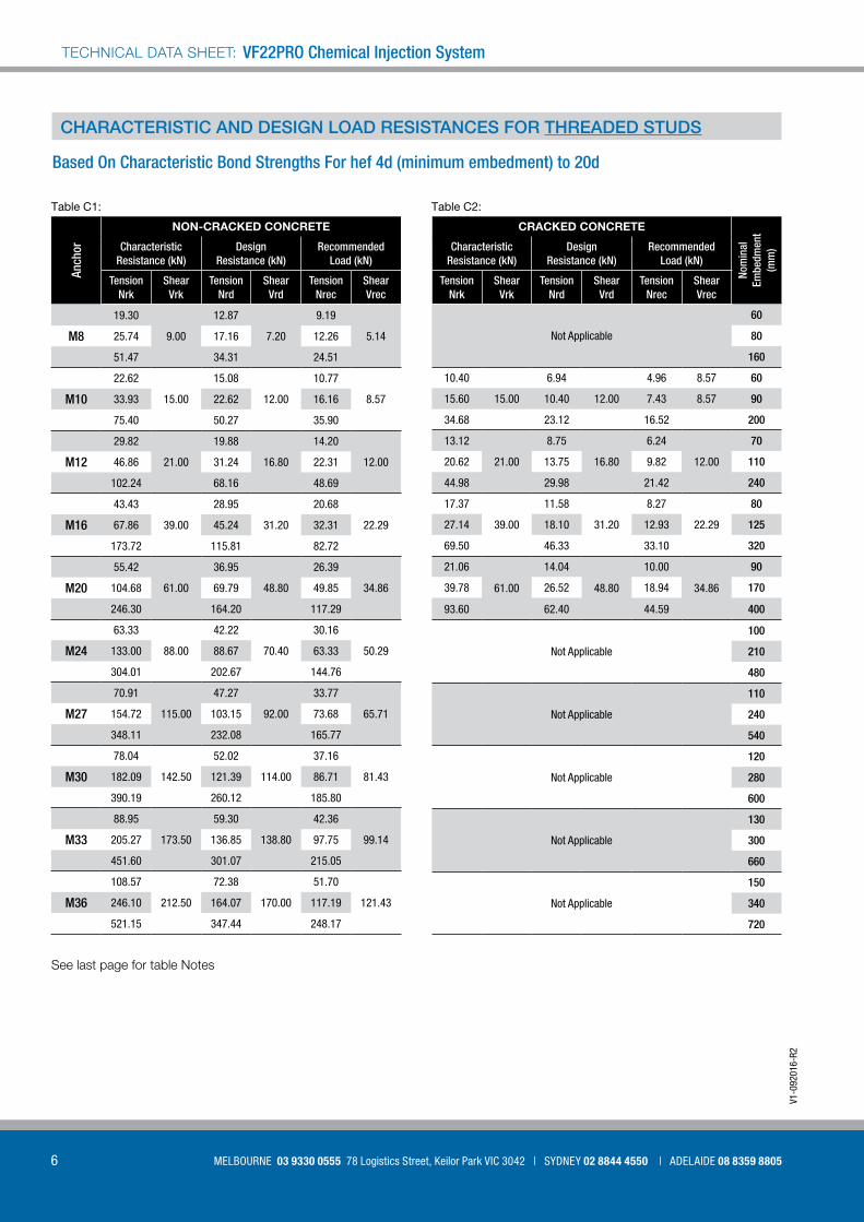
CHARACTERISTIC AND DESIGN LOAD RESISTANCES FOR THREADED STUDS
Based On Characteristic Bond Strengths For hef 4d (minimum embedment) to 20d
Table C1:
Anch
or
NON-CRACKED CONCRETE
Characteristic Resistance (kN)
Design Resistance (kN)
Recommended Load (kN)
TensionNrk
ShearVrk
TensionNrd
ShearVrd
TensionNrec
ShearVrec
19.30
9.00
12.87
7.20
9.19
5.14M8 25.74 17.16 12.26
51.47 34.31 24.51
22.62
15.00
15.08
12.00
10.77
8.57M10 33.93 22.62 16.16
75.40 50.27 35.90
29.82
21.00
19.88
16.80
14.20
12.00M12 46.86 31.24 22.31
102.24 68.16 48.69
43.43
39.00
28.95
31.20
20.68
22.29M16 67.86 45.24 32.31
173.72 115.81 82.72
55.42
61.00
36.95
48.80
26.39
34.86M20 104.68 69.79 49.85
246.30 164.20 117.29
63.33
88.00
42.22
70.40
30.16
50.29M24 133.00 88.67 63.33
304.01 202.67 144.76
70.91
115.00
47.27
92.00
33.77
65.71M27 154.72 103.15 73.68
348.11 232.08 165.77
78.04
142.50
52.02
114.00
37.16
81.43M30 182.09 121.39 86.71
390.19 260.12 185.80
88.95
173.50
59.30
138.80
42.36
99.14M33 205.27 136.85 97.75
451.60 301.07 215.05
108.57
212.50
72.38
170.00
51.70
121.43M36 246.10 164.07 117.19
521.15 347.44 248.17
See last page for table Notes
Table C2:
CRACKED CONCRETE
Nom
inal
Em
bedm
ent
(mm
)Characteristic Resistance (kN)
Design Resistance (kN)
Recommended Load (kN)
TensionNrk
ShearVrk
TensionNrd
ShearVrd
TensionNrec
ShearVrec
Not Applicable
60
80
160
10.40 6.94 4.96 8.57 60
15.60 15.00 10.40 12.00 7.43 8.57 90
34.68 23.12 16.52 200
13.12
21.00
8.75
16.80
6.24
12.00
70
20.62 13.75 9.82 110
44.98 29.98 21.42 240
17.37
39.00
11.58
31.20
8.27
22.29
80
27.14 18.10 12.93 125
69.50 46.33 33.10 320
21.06
61.00
14.04
48.80
10.00
34.86
90
39.78 26.52 18.94 170
93.60 62.40 44.59 400
Not Applicable
100
210
480
Not Applicable
110
240
540
Not Applicable
120
280
600
Not Applicable
130
300
660
Not Applicable
150
340
720

7
VF22PRO
[email protected] more information call 1800 255 349 | WWW.ALLFASTENERS.COM.AU
BOND STRENGTH FACTORS - THREADED STUDS
Influence of environmental conditions in NON-CRACKED concrete
Table D2:
Threaded Rods M8 M10 M12 M16 M20 M24 M27 M30 M33 M36
Temp I 40°C / 24°C
Dry and Wet
1.00 1.00 1.00 1.00 1.00 1.00 1.00 1.00 1.00 1.00
Temp II 80°C / 50°C
0.90 0.88 0.87 0.86 0.85 0.84 0.83 0.82 0.81 0.80
Influence of environmental conditions in CRACKED concrete
Table D3:
Threaded Rods M8 M10 M12 M16 M20 M24 M27 M30
Temp I 40°C / 24°C
Dry and Wet
n/a 0.46 0.44 0.40 0.38 n/a n/a n/a
Temp II 80°C / 50°C
n/a 0.45 0.43 0.40 0.38 n/a n/a n/a
See last page for table Notes
Influence of concrete strength on combined pull out and concrete cone resistance
Table D1:
Concrete Strength N/mm2 (MPa)
C15/20 C20/25 C25/30 C30/37 C35/45 C40/50 C45/55 C50/60
Non cracked fc = 0.82 0.88 0.94 1 1.06 1.12 1.17 1.23
Cracked fc = 0.91 0.95 0.96 1 1.03 1.05 1.06 1.07

8
VF22PRO Chemical Injection SystemTECHNICAL DATA SHEET:
MELBOURNE 03 9330 0555 78 Logistics Street, Keilor Park VIC 3042 | SYDNEY 02 8844 4550 | ADELAIDE 08 8359 8805
V1-0
9201
6-R2
CHARACTERISTIC AND DESIGN LOAD RESISTANCES FOR REBAR
For REBAR based on characteristic bond strengths for hef 4d (min embedment) to 20d
Table E1:
Reba
r Ø(m
m)
NON-CRACKED CONCRETE
Characteristic Resistance (kN)
Design Resistance (kN)
Recommended Load (kN)
TensionNrk
ShearVrk
TensionNrd
ShearVrd
TensionNrec
ShearVrec
15.68
13.95
8.71
9.30
6.22
6.648 20.91 11.62 8.30
41.82 23.23 16.60
18.66
21.45
10.37
14.30
7.41
10.2110 27.99 15.55 11.11
62.20 34.56 24.68
24.70
31.05
13.72
20.70
9.80
14.7912 38.82 21.56 15.40
84.69 47.05 33.61
31.67
42.45
17.59
28.30
12.57
20.2114 45.52 25.29 18.06
110.84 61.58 43.98
34.74
55.50
19.30
37.00
13.79
26.4316 54.29 30.16 21.54
138.97 77.21 55.15
37.55
69.66
20.86
46.44
14.90
33.1718 70.40 39.11 27.94
168.97 93.87 67.05
36.76
86.55
20.42
57.70
14.59
41.2120 69.43 38.57 27.55
163.36 90.76 64.83
44.92
104.01
24.96
69.34
17.83
49.5322 85.36 47.42 33.87
197.67 109.82 78.44
51.05
135.00
28.36
90.00
20.26
64.2925 107.21 59.56 42.54
255.26 141.81 101.29
61.08
168.75
33.93
112.50
24.24
80.3628 152.71 84.84 60.60
305.41 169.67 121.20
77.21
220.95
42.89
147.30
30.64
105.2132 193.02 107.23 76.60
386.04 214.47 153.19
See last page for table Notes
Table E2:
CRACKED CONCRETE
Nom
inal
Em
bedm
ent
(mm
)Characteristic Resistance (kN)
Design Resistance (kN)
Recommended Load (kN)
TensionNrk
ShearVrk
TensionNrd
ShearVrd
TensionNrec
ShearVrec
Not Applicable
60
80
160
Not Applicable
60
90
200
10.56
31.05
5.86
20.70
4.19
14.79
70
16.59 9.22 6.58 110
36.19 20.11 14.36 240
13.72
42.45
7.62
28.10
5.45
20.07
80
19.73 10.96 7.83 115
48.03 26.68 19.06 280
15.28
55.50
8.49
37.00
6.06
26.43
80
23.88 13.26 9.47 125
61.12 33.96 24.26 320
16.51
69.66
9.17
46.44
6.55
33.17
80
30.96 17.20 12.29 150
74.31 41.28 29.49 360
19.79
86.55
11.00
57.70
7.85
41.21
90
37.39 20.77 14.84 170
87.96 48.87 34.91 400
24.19
104.00
13.44
69.34
9.60
49.53
100
45.96 25.53 18.24 190
106.44 59.13 42.24 440
27.49 135.00 15.27 90.00 10.91 64.29 100
57.73 32.07 22.91 210
137.45 76.36 54.54 500
Not Applicable
112
280
560
Not Applicable
128
320
640

9
VF22PRO
[email protected] more information call 1800 255 349 | WWW.ALLFASTENERS.COM.AU
BOND STRENGTH FACTORS – REBAR
Influence of concrete strength on combined pull out and concrete cone resistance
Table F1:
Concrete Strength N/mm2 (MPa)
C15/20 C20/25 C25/30 C30/37 C35/45 C40/50 C45/55 C50/60
Non cracked fc = 0.82 0.88 0.94 1 1.06 1.12 1.17 1.23
Cracked fc = 0.91 0.95 0.96 1 1.03 1.05 1.06 1.07
Influence of environmental conditions in NON-CRACKED concrete
Table F2:
Rebar Ø 8 Ø 10 Ø 12 Ø 14 Ø 16 Ø 18 Ø 20 Ø 22 Ø 25 Ø 28 Ø 32
Temp I 40°C / 24°C Dry and
Wet
1.00 1.00 1.00 1.00 1.00 1.00 1.00 1.00 1.00 1.00 1.00
Temp II 80°C / 50°C
0.90 0.90 0.88 0.88 0.88 0.86 0.86 0.86 0.86 0.84 0.84
Influence of environmental conditions in CRACKED concrete
Table F3:
Rebar Ø 8 Ø 10 Ø 12 Ø 14 Ø 16 Ø 18 Ø 20 Ø 22 Ø 25 Ø 28 Ø 32
Temp I 40°C / 24°C Dry and
Wet
n/a n/a 0.43 0.43 0.43 0.43 0.53 0.53 0.53 n/a n/a
Temp II 80°C / 50°C
n/a n/a 0.38 0.38 0.38 0.38 0.46 0.46 0.46 n/a n/a
See last page for table Notes
10
VF22PRO Chemical Injection SystemTECHNICAL DATA SHEET:
MELBOURNE 03 9330 0555 78 Logistics Street, Keilor Park VIC 3042 | SYDNEY 02 8844 4550 | ADELAIDE 08 8359 8805
V1-0
9201
6-R2
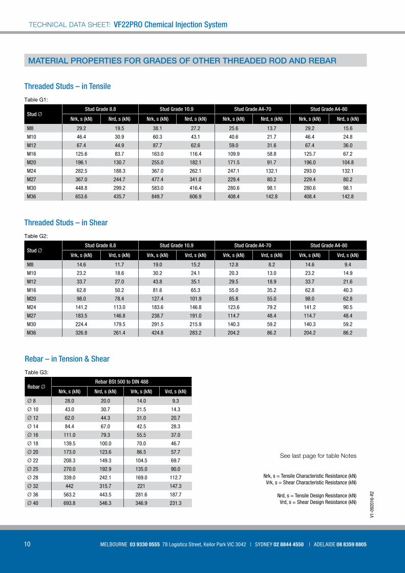
MATERIAL PROPERTIES FOR GRADES OF OTHER THREADED ROD AND REBAR
See last page for table Notes
Threaded Studs – in Tensile
Table G1:
Stud ØStud Grade 8 8 Stud Grade 10 9 Stud Grade A4-70 Stud Grade A4-80
Nrk, s (kN) Nrd, s (kN) Nrk, s (kN) Nrd, s (kN) Nrk, s (kN) Nrd, s (kN) Nrk, s (kN) Nrd, s (kN)
M8 29.2 19.5 38.1 27.2 25.6 13.7 29.2 15.6
M10 46.4 30.9 60.3 43.1 40.6 21.7 46.4 24.8
M12 67.4 44.9 87.7 62.6 59.0 31.6 67.4 36.0
M16 125.6 83.7 163.0 116.4 109.9 58.8 125.7 67.2
M20 196.1 130.7 255.0 182.1 171.5 91.7 196.0 104.8
M24 282.5 188.3 367.0 262.1 247.1 132.1 293.0 132.1
M27 367.0 244.7 477.4 341.0 229.4 80.2 229.4 80.2
M30 448.8 299.2 583.0 416.4 280.6 98.1 280.6 98.1
M36 653.6 435.7 849.7 606.9 408.4 142.8 408.4 142.8
Threaded Studs – in Shear
Table G2:
Stud ØStud Grade 8 8 Stud Grade 10 9 Stud Grade A4-70 Stud Grade A4-80
Vrk, s (kN) Vrd, s (kN) Vrk, s (kN) Vrd, s (kN) Vrk, s (kN) Vrd, s (kN) Vrk, s (kN) Vrd, s (kN)
M8 14.6 11.7 19.0 15.2 12.8 8.2 14.6 9.4
M10 23.2 18.6 30.2 24.1 20.3 13.0 23.2 14.9
M12 33.7 27.0 43.8 35.1 29.5 18.9 33.7 21.6
M16 62.8 50.2 81.6 65.3 55.0 35.2 62.8 40.3
M20 98.0 78.4 127.4 101.9 85.8 55.0 98.0 62.8
M24 141.2 113.0 183.6 146.8 123.6 79.2 141.2 90.5
M27 183.5 146.8 238.7 191.0 114.7 48.4 114.7 48.4
M30 224.4 179.5 291.5 215.9 140.3 59.2 140.3 59.2
M36 326.8 261.4 424.8 283.2 204.2 86.2 204.2 86.2
Rebar – in Tension & Shear
Table G3:
Rebar ØRebar BSt 500 to DIN 488
Nrk, s (kN) Nrd, s (kN) Vrk, s (kN) Vrd, s (kN)
Ø 8 28.0 20.0 14.0 9.3
Ø 10 43.0 30.7 21.5 14.3
Ø 12 62.0 44.3 31.0 20.7
Ø 14 84.4 67.0 42.5 28.3
Ø 16 111.0 79.3 55.5 37.0
Ø 18 139.5 100.0 70.0 46.7
Ø 20 173.0 123.6 86.5 57.7
Ø 22 208.3 149.3 104.5 69.7
Ø 25 270.0 192.9 135.0 90.0
Ø 28 339.0 242.1 169.0 112.7
Ø 32 442 315.7 221 147.3
Ø 36 563.2 443.5 281.6 187.7
Ø 40 693.8 546.3 346.9 231.3
Nrk, s = Tensile Characteristic Resistance (kN) Vrk, s = Shear Characteristic Resistance (kN)
Nrd, s = Tensile Design Resistance (kN)Vrd, s = Shear Design Resistance (kN)

11
VF22PRO
[email protected] more information call 1800 255 349 | WWW.ALLFASTENERS.COM.AU
Table i1:
Anchor Spacing
STUD / REBAR DIAMETERAnchor Spacing
(mm) 8 10 12 16 20 24 27 30 33 36 40 (mm)
40 0.64 4050 0.67 0.63 5060 0.70 0.65 0.63 6070 0.73 0.67 0.64 7080 0.76 0.69 0.66 0.63 8090 0.79 0.72 0.68 0.64 90100 0.82 0.74 0.70 0.65 0.63 100120 0.87 0.79 0.74 0.68 0.65 0.63 120150 0.96 0.86 0.80 0.73 0.68 0.65 0.64 0.63 150160 1.00 0.88 0.82 0.74 0.70 0.66 0.65 0.63 0.62 0.63 160180 0.93 0.86 0.77 0.72 0.68 0.65 0.65 0.64 0.64 0.64 180200 1.00 0.90 0.80 0.74 0.69 0.67 0.66 0.65 0.65 0.65 200225 0.95 0.84 0.77 0.72 0.69 0.68 0.67 0.67 0.66 225240 1.00 0.86 0.79 0.73 0.71 0.69 0.69 0.68 0.67 240250 0.87 0.80 0.74 0.72 0.70 0.70 0.68 0.68 250275 0.91 0.83 0.76 0.74 0.72 0.72 0.70 0.69 275280 0.92 0.84 0.77 0.75 0.73 0.72 0.70 0.69 280300 0.95 0.86 0.79 0.76 0.74 0.74 0.72 0.71 300320 1.00 0.88 0.81 0.78 0.76 0.75 0.73 0.72 320350 0.92 0.83 0.81 0.78 0.78 0.75 0.73 350400 1.00 0.88 0.86 0.82 0.82 0.78 0.76 400440 0.92 0.89 0.85 0.85 0.81 0.79 440460 1.00 0.91 0.87 0.87 0.82 0.80 460500 0.95 0.90 0.90 0.85 0.82 500540 1.00 0.93 0.93 0.88 0.84 540560 1.00 0.95 0.89 0.86 560620 1.00 0.93 0.89 620660 1.00 0.91 660720 1.00 720
INFLUENCES OF ANCHOR SPACING AND EDGE DISTANCE
Effect of Anchor Spacing - Tension
Edge Distance
TENSION
SHEAR
Anchor Spacing
12
VF22PRO Chemical Injection SystemTECHNICAL DATA SHEET:
MELBOURNE 03 9330 0555 78 Logistics Street, Keilor Park VIC 3042 | SYDNEY 02 8844 4550 | ADELAIDE 08 8359 8805
V1-0
9201
6-R2
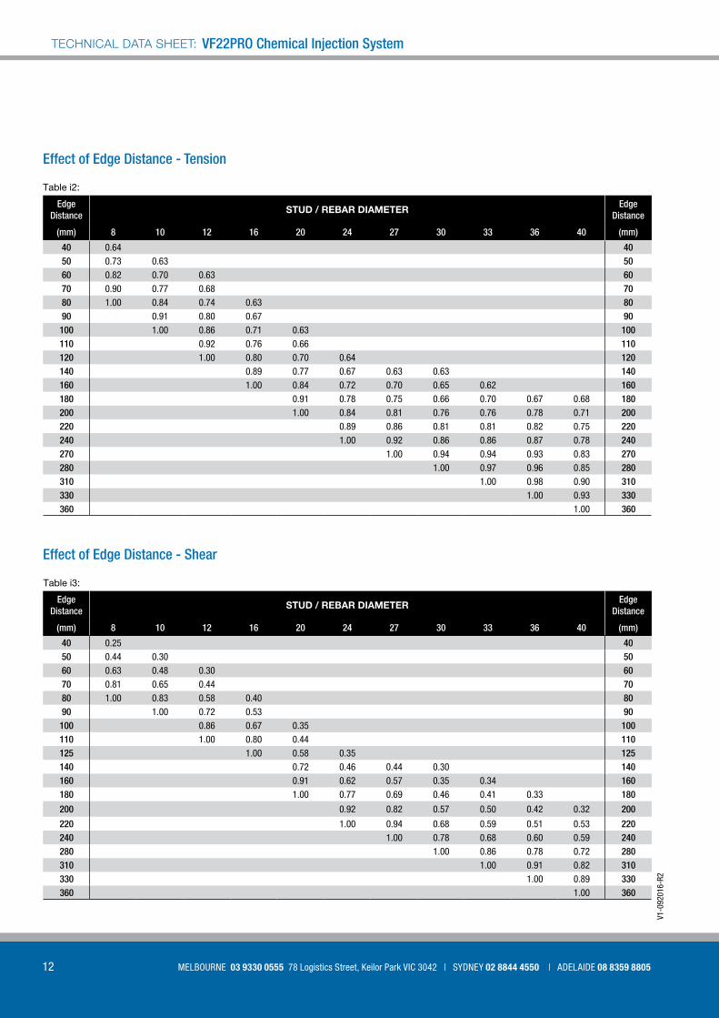
Table i2:
Edge Distance
STUD / REBAR DIAMETEREdge
Distance
(mm) 8 10 12 16 20 24 27 30 33 36 40 (mm)
40 0.64 4050 0.73 0.63 5060 0.82 0.70 0.63 6070 0.90 0.77 0.68 7080 1.00 0.84 0.74 0.63 8090 0.91 0.80 0.67 90100 1.00 0.86 0.71 0.63 100110 0.92 0.76 0.66 110120 1.00 0.80 0.70 0.64 120140 0.89 0.77 0.67 0.63 0.63 140160 1.00 0.84 0.72 0.70 0.65 0.62 160180 0.91 0.78 0.75 0.66 0.70 0.67 0.68 180200 1.00 0.84 0.81 0.76 0.76 0.78 0.71 200220 0.89 0.86 0.81 0.81 0.82 0.75 220240 1.00 0.92 0.86 0.86 0.87 0.78 240270 1.00 0.94 0.94 0.93 0.83 270280 1.00 0.97 0.96 0.85 280310 1.00 0.98 0.90 310330 1.00 0.93 330360 1.00 360
Table i3:
Edge Distance
STUD / REBAR DIAMETEREdge
Distance
(mm) 8 10 12 16 20 24 27 30 33 36 40 (mm)
40 0.25 4050 0.44 0.30 5060 0.63 0.48 0.30 6070 0.81 0.65 0.44 7080 1.00 0.83 0.58 0.40 8090 1.00 0.72 0.53 90100 0.86 0.67 0.35 100110 1.00 0.80 0.44 110125 1.00 0.58 0.35 125140 0.72 0.46 0.44 0.30 140160 0.91 0.62 0.57 0.35 0.34 160180 1.00 0.77 0.69 0.46 0.41 0.33 180
200 0.92 0.82 0.57 0.50 0.42 0.32 200
220 1.00 0.94 0.68 0.59 0.51 0.53 220240 1.00 0.78 0.68 0.60 0.59 240280 1.00 0.86 0.78 0.72 280310 1.00 0.91 0.82 310330 1.00 0.89 330360 1.00 360
Effect of Edge Distance - Tension
Effect of Edge Distance - Shear
13
VF22PRO
[email protected] more information call 1800 255 349 | WWW.ALLFASTENERS.COM.AU
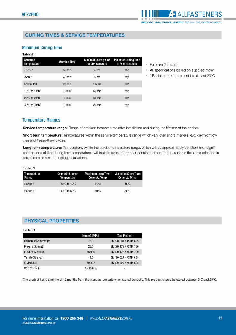
Minimum Curing Time Table J1:
Concrete Temperature
Working TimeMinimum curing time
in DRY concreteMinimum curing time
in WET concrete
-10°C * 50 min 4 hrs x 2
-5°C * 40 min 3 hrs x 2
5°C to 9°C 20 min 1.5 hrs x 2
10°C to 19°C 9 min 60 min x 2
20°C to 29°C 5 min 30 min x 2
30°C to 39°C 3 min 20 min x 2
§§ Full cure 24 hours
§§ All specifications based on supplied mixer
§§ * Resin temperature must be at least 20°C
Temperature Ranges
PHYSICAL PROPERTIES
Table J2:
Temperature Range
Concrete Service Temperature
Maximum Long Term Concrete Temp
Maximum Short Term Concrete Temp
Range I -40°C to 40°C 24°C 40°C
Range II -40°C to 60°C 50°C 80°C
Service temperature range: Range of ambient temperatures after installation and during the lifetime of the anchor.
Short term temperature: Temperatures within the service temperature range which vary over short intervals, e.g. day/night cy-cles and freeze/thaw cycles.
Long term temperature: Temperature, within the service temperature range, which will be approximately constant over signifi-cant periods of time. Long term temperatures will include constant or near constant temperatures, such as those experienced in cold stores or next to heating installations.
Table K1:
N/mm2 (MPa) Test Method
Compressive Strength 73.0 EN ISO 604 / ASTM 695
Flexural Strength 25.0 EN ISO 178 / ASTM 790
Flexural Modulus 3850.0 EN ISO 178 / ASTM 790
Tensile Strength 14.6 EN ISO 527 / ASTM 638
E Modulus 8029.7 EN ISO 527 / ASTM 638
VOC Content A+ Rating -
CURING TIMES & SERVICE TEMPERATURES
The product has a shelf life of 12 months from the manufacture date when stored correctly. This product should be stored between 5°C and 25°C.
14
VF22PRO Chemical Injection SystemTECHNICAL DATA SHEET:
MELBOURNE 03 9330 0555 78 Logistics Street, Keilor Park VIC 3042 | SYDNEY 02 8844 4550 | ADELAIDE 08 8359 8805
V1-0
9201
6-R2
INSTALLATION PARAMETERS: DRILLING HOLE CLEANING AND INSTALLATION
1
x2
2
x2
x2
2
x2
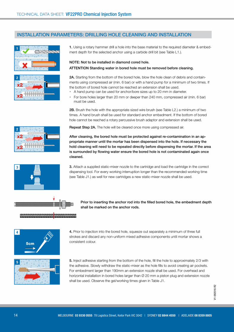
1. Using a rotary hammer drill a hole into the base material to the required diameter & embed-ment depth for the selected anchor using a carbide drill bit (see Table L1.).
2A. Starting from the bottom of the bored hole, blow the hole clean of debris and contain-ments using compressed air (min. 6 bar) or with a hand pump for a minimum of two times. If the bottom of bored hole cannot be reached an extension shall be used.§§ A hand pump can be used for anchor/bore sizes up to 20 mm in diameter.
§§ For bore holes larger than 20 mm or deeper than 240 mm, compressed air (min. 6 bar) must be used.
2B. Brush the hole with the appropriate sized wire brush (see Table L2.) a minimum of two times. A hand brush shall be used for standard anchor embedment. If the bottom of bored hole cannot be reached a rotary percussive brush adaptor and extension shall be used.
Repeat Step 2A. The hole will be cleared once more using compressed air.
3. Attach a supplied static-mixer nozzle to the cartridge and load the cartridge in the correct dispensing tool. For every working interruption longer than the recommended working time (see Table J1.) as well for new cartridges a new static-mixer nozzle shall be used.
4. Prior to injection into the bored hole, squeeze out separately a minimum of three full strokes and discard any non-uniform mixed adhesive components until mortar shows a consistent colour.
5. Inject adhesive starting from the bottom of the hole, fill the hole to approximately 2/3 with the adhesive. Slowly withdraw the static-mixer as the hole fills to avoid creating air pockets. For embedment larger than 190mm an extension nozzle shall be used. For overhead and horizontal installation in bored holes larger than Ø 20 mm a piston plug and extension nozzle shall be used. Observe the gel/working times given in Table J1.
Prior to inserting the anchor rod into the filled bored hole, the embedment depth shall be marked on the anchor rods.
After cleaning, the bored hole must be protected against re-contamination in an ap-propriate manner until the mortar has been dispensed into the hole. If necessary the hold cleaning will need to be repeated directly before dispensing the mortar. If the area is surrounded by flowing water ensure the bored hole is not contaminated again once cleaned.
ATTENTION Standing water in bored hole must be removed before cleaning.
NOTE: Not to be installed in diamond cored hole.
3
5cm
4
5

15
VF22PRO
[email protected] more information call 1800 255 349 | WWW.ALLFASTENERS.COM.AU
tcure7
tinst
8
6 6. Push the threaded rod or rebar into the hole while turning slightly to ensure positive distri-bution of the adhesive until the embedment depth is reached. The anchor should be free of dirt, grease, oil and other foreign containments.
Be sure that the anchor is fully seated at the bottom of the hole and that excess mortar is visi-ble at the top of the hole. If these requirements are not maintained, the application has to be renewed. For overhead application the anchor rod should be secured i.e. with wedges
7. Allow the adhesive to cure to the specified time prior to applying any load or torque. Do not move or load the anchor until it is fully cured (see Table J1.)
8. After full curring, the add-on/fixture can to installed with the max torque applied (see Table L1) by using a calibrated torque wrench.
hef = ho
≥ hmin
dO da
t�xdO = hole diameterhef = effective anchorage depthhO = depth of drilled holehmin = base material thicknesstfix = fixtureda = anchor diameter
Table L1:
Threaded Rod M8 M10 M12 M16 M20 M24
Nominal Drill Bit Ø do (mm) 10 12 14 18 24 28
Range of anchor depth hef
and bore hole depth hO
hef,min (mm) 60 60 70 80 90 96
hef,max (mm) 160 200 240 320 400 480
Ø of clearance in fixture df (mm) ≤ 9 12 14 18 22 26
Torque (MAX) tinst (Nm) ≤ 10 20 30 60 90 140
Minimum Depth of Base Material hmin (mm) hef + 30mm ≥ 100mm hef + 2 do
Minimum Spacing Smin (mm)40 50 60 80 100 120
Minimum Edge Distance Cmin (mm)
Rebar Ø8 Ø10 Ø12 Ø14 Ø16 Ø20 Ø25
Nominal Drill Bit Ø do (mm) 12 14 16 18 20 25 32
ALLFASTENERS Chem Stud M8 M10 M12 M16 M20 M24
Effective Anchorage Depth hef,rec (mm) 80 90 110 125 170 210
Fixture Thickness tfix,min (mm) 17 25 33 44 64 56

16
VF22PRO Chemical Injection SystemTECHNICAL DATA SHEET:
MELBOURNE 03 9330 0555 78 Logistics Street, Keilor Park VIC 3042 | SYDNEY 02 8844 4550 | ADELAIDE 08 8359 8805
V1-0
9201
6-R2
Table L2:
AnchorØ Size (mm)
Drill Bit Ø (mm) Wire Brush Ø, do (mm) Wire Brush min Ø (mm) Piston Plug
ThreadedRod
M8 10 12 10.5 -
M10 12 14 12.5 -
M12 14 16 14.5 -
M16 18 20 18.5 -
M20 24 26 24.5 #24
M24 28 30 28.5 #28
M27 32 34 32.5 #32
M30 35 37 35.5 #35
Rebar
Ø 8 12 14 12.5 -
Ø 10 14 16 14.5 -
Ø 12 16 18 16.5 -
Ø 14 18 20 18.5 -
Ø 16 20 22 20.5 -
Ø 20 24 26 24.5 #24
Ø 25 32 34 32.5 #32
Ø 28 35 37 35.5 #35
Ø 32 40 41.5 38.5 #38
Cleaning & Setting tools
Hand Pump (vol. 750ml) 12BPUMP Drill bit diameter (do) : 10mm to 20mm
Compressed Air Tool (min. 6 bar) Drill bit diameter (do) : 10mm to 40mm
Applicator Tool 12CAG410 410ml 10:1
17
VF22PRO
[email protected] more information call 1800 255 349 | WWW.ALLFASTENERS.COM.AU
NOTES
PAGE 3: Typical characteristic and design resistance performance with 5.8 grade studding and associated installation data § All data is based on correct installation - see instructions
§ No influence of edge and spacing
§ Minimum base material thickness hef +30mm >100mm for M8 to M12 and for M16 to M30 hef +2 d
§ hef range minimum or 4d whichever is greatest to 20d
§ Concrete strength C30/37 - fc cube = 37N/mm2 (32MPa)
§ 5.8 grade stud
§ Temperature range I maximum long term / short term temperature +24/40oC
PAGE 4-5: Design Resistance with various stud strengths, material and rebar. § Note 1 for stainless steel tensile strength is 500N/mm2 (500MPa)
§ Note 2 for stainless steel tensile strength is 700N/mm2 (500MPa)
§ Data shown below the minimum embedment depth is for reference only. Please refer to manufacturer for advice.
PAGE 6 : Characteristic and Design Load resistances based on characteristic bond strengths for hef 4d (minimum embedment) to 20d § All data is based on correct installation - see instructions
§ No influence of edge and spacing
§ Minimum base material thickness hef +30mm >100mm for M8 to M12 and for M16 to M30 hef +2 d
§ hef range minimum or 4d whichever is greatest to 20d
§ Concrete strength C30/37 - fc cube = 37N/mm2 (32MPa)
§ Temperature range i maximum long term / short term temperature +24/40oC
PAGE 7 & 9: Bond Strength Factors § Select concrete strength and environmental condition and apply to bond strength table on page 6 & 8
PAGE 10: Material Properties for grades of other threaded rod and rebar § All grades shown for information
§ M30 studding is 8.8 grade instead of 5.8 grade. >M27 for A4-70 tensile strength of 500N/mm2, instead of 700N/mm2
§ M30 for A4-70 tensile strength of 500N/mm2 (500MPa), instead of 700N/mm2 (700MPa)
§ Safety factor is 1.5 tension and 1.25 shear for all carbon steel
§ Safety factor is 1.87 for stainless steel, up to M24, M27 to M36 is 2.86
§ Safety factor is 1.56 for stainless steel in shear, up to M24, M27 to M36 is 2.37
§ Safety factor is 1.4 tension and 1.5 shear for BSt 500 rebar
Partial Safety Factors for pages 3 - 6, 8: 1.5 for all sizes studs
1.8 for all sizes rebar
IMPORTANT: Information, specifications, procedures and recommendations provided (“information”) are based on our experience and we believe this to be accurate. No representation, guarantee or warranty is made as
to the accuracy or completeness of the information or that use of the product will avoid losses or damages or give desired results. It is purchaser’s sole responsibility to test and determine the suitability of any product for the
intended use. Tests should be repeated if materials or conditions change in any way. No employee, distributor or agent has any right to change these facts and offer a guarantee of performance.
NOTE TO USER: by ordering/receiving product you accept the ALLFASTENERS General Terms and Conditions of Sale applicable in the region. Please request a copy if you have not received these. These Terms and Conditions
contain disclaimers of implied warranties (including but not limited to disclaiming warranties of fitness for a particular purpose) and limits of liability.