Embed Size (px)
Citation preview

www.belimo.com T5-SY3-24-MF-T • en • v1.0 • 01.2009 • Subject to changes 1 / 7
Technical data sheet SY3-24-MF-T
Multifunctional rotary actuator for butterfly valves• Torque 150 Nm• Nominal volta�e 24 �ominal volta�e 24 � 24 �• �ontrol�� confi�urable�ontrol�� confi�urable• Position feedback�� confi�urable• 2 �u�iliary switches�u�iliary switches• State at loss of si�nal�� closed
Technical data
Electrical dataNominal voltage AC 24 V, 50/60 Hz
AC/DC 24 V, 50/60 HzFor 3-lead connectionFor 4-lead connection
Power supply range AC/DC 21.6 ... 26.4 VPower consumption 70 W @ nominal torqueCurrent consumption 3.0 AAuxiliary switch 2 x EPU, 5 A, AC 230 V II
Switching points: 90°Connection Terminals, 2 x 1.5 mm2 or 1 x 2.5 mm2
Parallel connection Supply voltage Not possibleController signals Only for 4-lead connection possible
Functional data �ariable Settin�sTorque (nominal torque) Min. 150 Nm @ nominal voltageControl Control signal Y
Operating rangeDC 0 ... 10 V, input impedance 100 k�DC 0.5 ... 10 V
Starting pointEnd point
DC 0.5 ... 30 VDC 2.5 ... 32 V ................................
Control Control signal Y 4 mA ... 20 mA Non-variablePosition feedback Measuring voltage U5 DC 0 ... 10 V, max. 0.5 mA
DC 2 ... 10 V, max. 0.5 mAStarting pointEnd point
DC 0.5 ... 8 VDC 2.5 ... 10 V ................................
4 mA ... 20 mA Non-variablePosition accuracy ±5% absoluteManual override Temporary with handwheel (not revolving)Angle of rotation 90° (internal limit switch)Angle of rotation limiting MAX (maximum position)
MIN (minimum position)ZS (intermediate position)
= 100%= 0%= 50%
MAXMINZS
= (MIN + 32° ) ... 100%= 0% ... (MAX – 32° )= MIN ... MAX ................................
Running time 22 sDuty cycle 75% (e.g. 22s / 7s)Sound power level Max. 70 dB (A)Position indication Mechanical (integrated)
SafetyProtection class III Safety extra-low voltageDegree of protection IP67EMCLow-voltage directive
CE according to 2004/108/ECCE according to 2006/95/EC
Certification Tested in accordance with EN 61000-6-2 : 2005EN 61000-6-4 : 2007
Mode of operation Type 1 (EN 60730-1)Rated impulse voltage 500 V (EN 60730-1)Control pollution degree 4 (EN 60730-1)Ambient temperature –20 ... +60°CMedium temperature –20 ... +120°C (in the butterfly valve)
max. 130°C / 1 hNon-operating temperature –30 ... +80°CAmbient humidity 95% r.H., non-condensating (EN 60730-1)Maintenance Maintenance-free

SY3-24-MF-T Rotary actuator capable of communication, ��/D� 24 �, 150 Nm
2 / 7 T5-SY3-24-MF-T • en • v1.0 • 01.2009 • Subject to changes www.belimo.com
Product features
Mode of operation The actuator is controlled with a standard modulating signal and travels to the position defined by the control signal. The measuring voltage U serves for the electrical display of the actuator position 0 ... 100% and as slave control signal for other actuators.
Parameterisable actuators Input and output signals and other parameters can be altered with the BELIMO Service Tool, MFT-P.
Simple direct mountin� Simple direct mounting on the butterfly valve. The mounting position in relation to the butterfly valve can be selected in 90° steps.
Manual override The butterfly valve can be closed (turn clockwise) and opened (turn counterclockwise) with the handwheel. The handwheel does not move while the motor is running.
Internal heatin� An internal heater prevents condensation buildup.
Hi�h functional reliability Mechanical stops limit the actuator to –2° and 92° . The internal limit switches interrupt the voltage supply to the motor. In addition, a motor thermostat provides overload protection because at 135°C it interrupts the voltage supply.
�ombination butterfly valve actuators For suitable butterfly valves, their permitted media temperatures and closing pressures are refered to the butterfly valve documentation.
Technical data (continued)
Mechanical dataConnection flange ISO 5211 / F07Housing material Cast aluminium
Dimensions / Wei�htDimensions See «Dimensions» on page 6Weight Approx. 11 kg
Safety notes
!• The actuator has been desi�ned for use in stationary heatin�, ventilation and air conditionin�
systems and is not allowed to be used outside the specified field of application, especially in aircraft or in any other airborne means of transport.
• It may only be installed by suitably trained personnel. �ny le�al re�ulations or re�ulations issued by �overnment a�ency authorities must be
observed durin� assembly.• The device does not contain any parts that can be replaced or repaired by the user.• The device contains electrical and electronic components and is not allowed to be disposed
of as household refuse. �ll locally valid re�ulations and requirements must be observed.
�ccessories
Description
Electrical accessories PC-Tool MFT-P, beginning with v3.3�able ZK6-GEN�able ZK2-GEN

SY3-24-MF-T Rotary actuator capable of communication, ��/D� 24 �, 150 Nm
www.belimo.com T5-SY3-24-MF-T • en • v1.0 • 01.2009 • Subject to changes 3 / 7
Restrictions for 3-lead (and 4-lead) connector technolo�ies
The following overview shows the differences between the 24 V actuator wiring options.The same PCB (Print) can be used for both wirings.
3-lead connection 4-lead connection
Description Signal and connection to power supply have the same ground connection
Signal and connection to power supply have different ground connections
Supply volta�e AC only AC / DC
Ma�imum cable len�th* The maximum cable length is defined in the following connection diagram:
Wire cross-section 0.75 mm2 1.00 mm2 1.50 mm2 2.50 mm2 No limitation
SY 2 12 m 17 m 24 m 43 m No limitation
SY 3 12 m 17 m 24 m 43 m No limitation
SY 4 5 m 7 m 10 m 17 m No limitation
SY 5 5 m 7 m 10 m 17 m No limitation
Measurin� volta�e U5 U5 is stable as soon as the actuator stops No limitation
�ontrol si�nal m� Not possible The ground connection must be wired to the actuator with mA control signal
* The limitation regarding cable length is because of the large amounts of current required by the SY actuator.A high level of current will in turn have an influence on the signals.
Electrical installation for 3-lead connection
Wirin� dia�rams
LS3 LS4
100%
Y
U5
A B C
0%
D E F Y U5
T
1 ~
�ctuator Butterfly valveY1 � – �B = 100%
Y2 � – �B = 0%
�u�iliary switch
Position Butterfly valve
LS3 100% openLS4 0% closed
�ontrol si�nalMeasurin� volta�e
3-lead system connection
G
( )
( )
24 V AC
~
Y U5
T
1~
G
( )
( )
24 V AC
~
Y U5
T
1~
(-) of the control si�nal Y, (-) of the measurin� volta�e U5 and ( ) can be connected to�ether.
Measurin� volta�e U5
�ontrol si�nal Y
Ma�imum cable len�th
�� 24 �
Measurin� volta�e U5
�ontrol si�nal Y
Ma�imum cable len�th

SY3-24-MF-T Rotary actuator capable of communication, ��/D� 24 �, 150 Nm
4 / 7 T5-SY3-24-MF-T • en • v1.0 • 01.2009 • Subject to changes www.belimo.com
Functions with basic values - 3-lead connection technolo�y
Override control with �� 24 �with relay contacts
Override control with �� 24 �with rotary control switch
a b
c
~ T
Y U5~
Functions a b c
Loss of control signalCLOSED → 0% ZS 50% (intermediate position)
100%
Control mode in acc. with Y
1 2
4 3
~ T
Y U5~
Pos Functions
1 Loss of control signalCLOSED → 0%
2 ZS 50% (intermediate position)
3 100%
4 Control mode in acc. with Y
Remote control 0 ... 100% Minimum limit
SGA24
SGF24
SGE24 4
Y Z 2 1 3
T ~
~ T
Y U5~
DIP switchon Y2
DIP switchon Y1
Y = 2 V Y = 2 V
SGA24
SGF24
SGE24 4
Y Z 2 1 3
T ~
~ T
Y U5~
100 0
Y [�]
10
min
0 [%]
Master/Slave control (position-dependent) �ontrol with 4 ... 20 m� via e�ternal resistance
ZAD24
4 2 1 3
~ T
+ –
Y U5~
U DC 2 ... 10 V
(+)
(–) 4 ... 20 mA
~T
Y U5~
Y (D� 0 ... 10 �)From controller
Y (D� 0 ... 10 �)From controller
e.g. 1N 4007
e.g. 1N 4007
Positioner Positioner
Y (D� 0 ... 10 �)From controller
�daptin� the direction of rotation
Functions for MF actuators with specific parameters - 3-lead connection technolo�y
3-point control Open-close control
U
T ~
a b
Y U5~
Direction of rotation switch
a b Y2 Y1
Stop Stop
U
T ~
+ –
Y U5~
The 500 � resistor converts the 4 ... 20 mA current signal to a voltage signal DC 2 ... 10 V
500 �

SY3-24-MF-T Rotary actuator capable of communication, ��/D� 24 �, 150 Nm
www.belimo.com T5-SY3-24-MF-T • en • v1.0 • 01.2009 • Subject to changes 5 / 7
Restrictions for 4-lead (and 3-lead) connector technolo�ies
The following overview shows the differences between the 24 V actuator wiring options.The same PCB (Print) can be used for both wirings.
3-lead connection 4-lead connection
Description Signal and connection to power supply have the same ground connection
Signal and connection to power supply have different ground connections
Supply volta�e AC only AC / DC
Ma�imum cable len�th* The maximum cable length is defined in the following connection diagram:
Wire cross-section 0.75 mm2 1.00 mm2 1.50 mm2 2.50 mm2 No limitation
SY 2 12 m 17 m 24 m 43 m No limitation
SY 3 12 m 17 m 24 m 43 m No limitation
SY 4 5 m 7 m 10 m 17 m No limitation
SY 5 5 m 7 m 10 m 17 m No limitation
Measurin� volta�e U5 U5 is stable as soon as the actuator stops No limitation
�ontrol si�nal m� Not possible The ground connection must be wired to the actuator with mA control signal
* The limitation regarding cable length is because of the large amounts of current required by the SY actuator.A high level of current will in turn have an influence on the signals.
Electrical installation for 4-lead connection
Wirin� dia�rams
LS3 LS4
100%
Y
U5
A B C
0%
D E F Y U5 1~
2
�ctuator Butterfly valveY1 � – �B = 100%
Y2 � – �B = 0%
�u�iliary switch
Position Butterfly valve
LS3 100% openLS4 0% closed
�ontrol si�nalMeasurin� volta�e
4-lead system connection
G
( )
( )
24 V AC
~
G
24 V AC
~
Y U51~
2 Y U51~
2
(-) of the control si�nal Y and (-) of the measurin� volta�e U5 can also be connected to�ether.
Measurin� volta�e U5
�ontrol si�nal Y
��/D� 24 �

SY3-24-MF-T Rotary actuator capable of communication, ��/D� 24 �, 150 Nm
6 / 7 T5-SY3-24-MF-T • en • v1.0 • 01.2009 • Subject to changes www.belimo.com
Settin�s
Settin� cam The setting cams for limit and auxiliary switches can be accessed by removing the housing cover.Optionally, auxiliary switches LS4/LS3 can be connected for signaling.Limit switches LS2/LS1 interrupt the voltage to the motor and are controlled by setting cams TC...The setting cams turn with the spindle. The butterfly valve closes when the stem is turning clockwise (cw) and opens when the stem is turning counterclockwise (ccw).
LS4
LS3
LS2
LS1
TC4
TC3
TC2
TC1
Settings of setting cams TC.. • TC4 for auxiliary switch position closed (factory setting 3° ).• TC3 for auxiliary switch position open (factory setting 87° ).• TC2 for limit switch closed (factory setting 0° ).• TC1 for limit switch open (factory setting 90° ).
Adjusting setting cams 1 Use a 2.5 mm Allen key to unscrew the corresponding setting cams TC..2 Turn the setting cam using the Allen key3 Set as shown in the illustration below4 Use the Allen key to tighten the setting cams
1
TC3 / TC1 (ccw)
2
TC3 / TC1 (cw)
TC
4 / T
C2 (
ccw
)
TC
4 / T
C2 (
cw
)
1
2
Adaptation An adaptation must take place after the TC1 and TC2 have been adjusted.
Important!Settings are only allowed to be made by authorised specialist personnel.
Stem
Dimensions [mm]
Dimensional drawin�s 326
181
289
30
123
208
4 x M8
SW
22
F07 (∅
70)
OPENCLOSEDCurrent positionDesired position

SY3-24-MF-T Rotary actuator capable of communication, ��/D� 24 �, 150 Nm
7 / 7 T5-SY3-24-MF-T • en • v1.0 • 01.2009 • Subject to changes www.belimo.com
Settin�s (continued)
Mechanical an�le of rotation limitation The mechanical angle of rotation is set at the factory to 92° and cannot be changed.The handwheel is rotated by means of a worm gear in a planetary gear unit. The gearing is stopped mechanically by means of two setscrews 1 and 2 (1½ rotations of the setscrews correspond to 2° ).Both limit switches LS2 /LS1 are set to 90° and must always switch off the motor before the mechanical angle of rotation limitation.
A
B
C� Angle of rotation limiting OPEN (90° )B �n�le of rotation limitin� �LOSED (0° )� Connection of handwheel for angle of rotation
limiting
Relationship between mechanical an�le of rotation limitin�, limit and au�iliary switches
–2° 0° 3° 87° 90° 92°
123
1 Auxiliary switch TC3 / TC42 Limit switch TC1 / TC23 Mechanical angle of rotation limitation (A + B)
Further documentation • Complete overview «The complete range of water solutions»• Data sheets, butterfly valves• Installation instructions for actuators and/or butterfly valves, respectively• Notes for project planning (hydraulic characteristic curves and circuits, installation regulations,
commissioning, maintenance. etc.)
�onnection and function elements
YU
5C
1C
2
T1
T2
A B C D E F
LS3 LS4
S1
S2
Y1Y2
T
F3
~
Yellow LED
Green LED
/ ~ Power supply voltageY1 Direction of rotation switch Actuator rotates counterclockwise (ccw), valve opens Y2 Direction of rotation switch Actuator rotates clockwise (cw) valve closesY Control signal
U5 Position feedback
T
1 /
T
2 0-lead (ground)F3 PC-tool connectionS1 Adaptation button Adaptation procedures is started (press S1 for 3 s)
Adaptation must take place after the TC1 and TC2 have been adjusted.
Yellow LED On Adaptation procedure activatedOff Standard operation
Green LED On In operationOff No voltage supply or fault
T Plug-in fuse Type T10A250VLS3 Auxiliary switch Factory setting 87°LS4 Auxiliary switch Factory setting 3°
�1 / �2 Not usedS2 Not used
www.belimo.com M5-SY..-24-..-T • v1.0 • 01.2009 1 / 3
7098
4-00
001.
A
SY..-24-..-T
100%1 2
OPENOPENOPEN
OPEN
OPENOPENOPEN
20 Nm3
2
4
1
O P E N OPE N O P E N
40 Nm3
2
4
1
4 x M8
4 x M10
±1°
CLOSED
CLOSED
CLOSED
CLOSED
3
54 6
DN125 ... DN200 = SW 17DN250 ... DN350 = SW 22
SW
SY2 ... SY3 = SW 13
SY4 ... SY5 = SW 17
2 / 3 M5-SY..-24-..-T • v1.0 • 01.2009 www.belimo.com
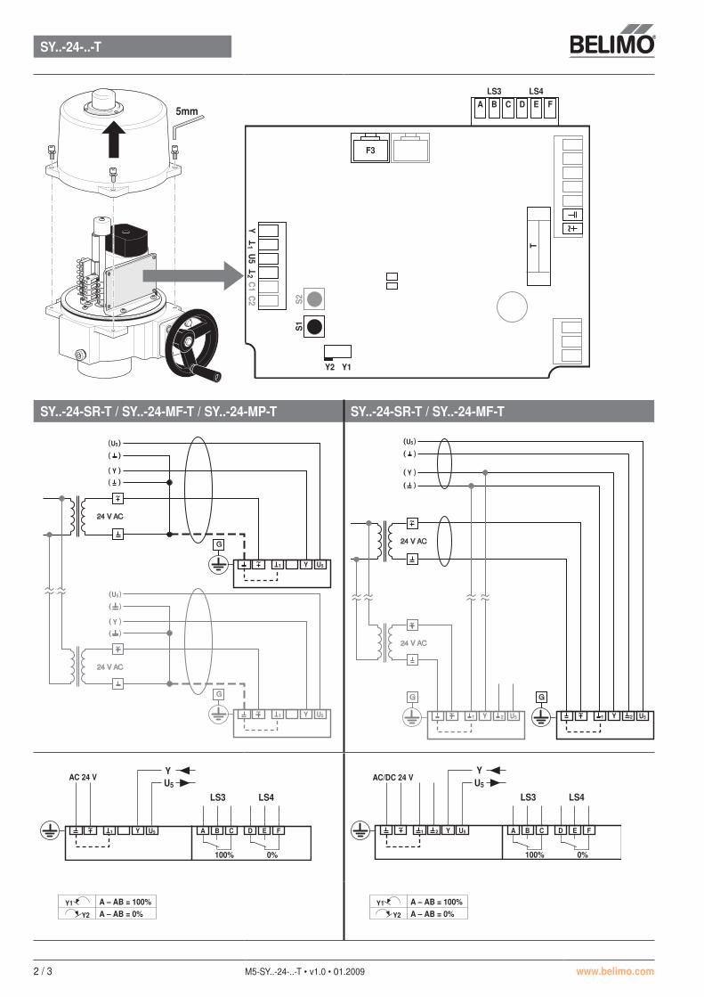
SY..-24-..-T
YU
5C
1C
2
T1
T2
A B C D E F
LS3 LS4
S1
S2
Y1Y2
T
F3
~
SY..-24-SR-T / SY..-24-MF-T / SY..-24-MP-T SY..-24-SR-T / SY..-24-MF-T
G
24 V AC
~
Y U5
T
1~
G
24 V AC
~
Y U5
T
1~
( )
( )
Y
U5( )
( )
( )
( )
Y
U5( )
( )
G
24 V AC
~
G
24 V AC
~
Y U51~
2 Y U51~
2
( )
( )
Y
U5( )
( )
LS3 LS4
100%
Y
U5
A B C
0%
D E F Y U5
T
1 ~
LS3 LS4
100%
Y
U5
A B C
0%
D E F Y U5 1~
2
Y1 A – AB = 100% Y2 A – AB = 0%
Y1 A – AB = 100% Y2 A – AB = 0%
5mm
AC 24 V AC/DC 24 V

SY..-24-..-T
www.belimo.com M5-SY..-24-..-T • v1.0 • 01.2009 3 / 3
SY..-24-MP-T
U5~ T
1U5~ T
1U5~ T
1
1 2 8
MP Master
L max.
U5
T
1 Y
~
MP
/
~
U5
T
1 Y
~
MP
/
~
U5
T
1 Y
~
MP
/
~
U5
T
1 Y
~∆p
MP
/
~
LS3 LS4
100%
Y
U5
A B C
0%
D E F Y U5 1~
2
AC 2
4 V
AC 2
4 V
AC 2
4 V
AC/DC 24 V AC/DC 24 V
AC/DC 24 V AC/DC 24 V