Embed Size (px)
Citation preview
RIELLO S.p.A. - Via degli Alpini, 1 - 37045 LEGNAGO (VR) ItalyTel. ++39.0442630111 - Fax ++39.044221980
Internet: http://www.rielloburners.com - E-mail: [email protected] 9001 Cert. n. 0061
TS0068UK00
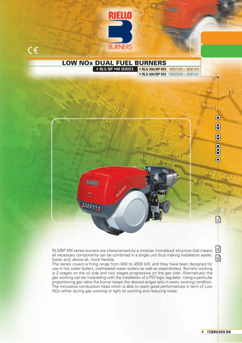
RLS/BP MX SERIES RLS 300/BP MX 600/1250 ÷ 3650 kWRLS 400/BP MX 1000/2000 ÷ 4500 kW
RLS/BP MX series burners are characterised by a modular monoblock structure that meansall necessary components can be combined in a single unit thus making installation easier,faster and, above all, more flexible.The series covers a firing range from 600 to 4500 kW, and they have been designed foruse in hot water boilers, overheated water boilers as well as steamboilers. Burners workingis 2 stages on the oil side and two stages progressive on the gas side. Alternatively thegas working can be modulating with the installation of a PID logic regulator. Using a particularproportioning gas valve the burner keeps the desired air/gas ratio in every working condition.The innovative combustion head which is able to reach good performances in term of LowNOx either during gas working or light oil working and reducing noise.
LOW NOx DUAL FUEL BURNERS
Since the Company is constantly engaged in the production improvement, the aesthetic anddimensional features, the technical data, the equipment and the accessories can be changed.
This document contains confidential and proprietary information of RIELLO S.p.A.Unless authorised, this information shall not be divulged, nor duplicated in whole or in part.
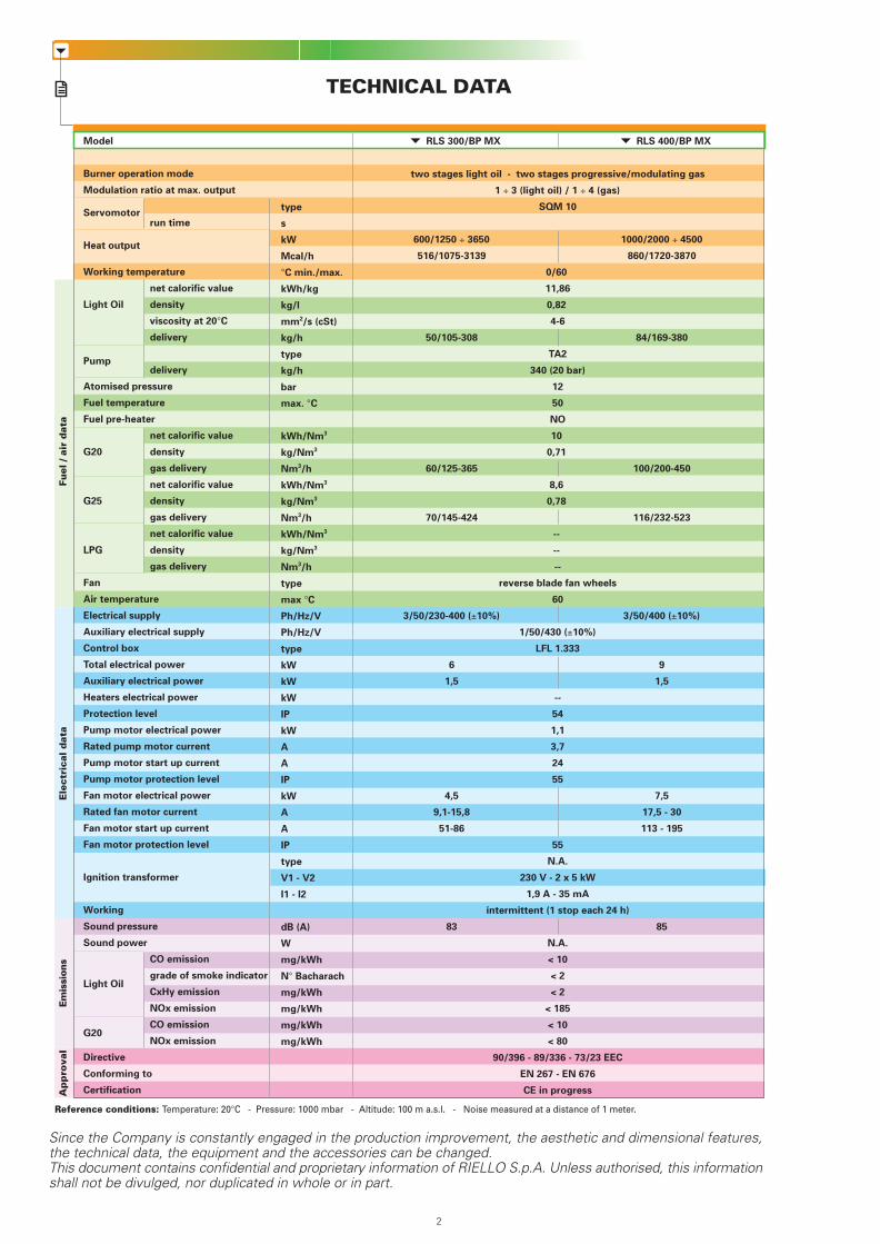
TECHNICAL DATAA
pp
rova
lFu
el /
air
dat
aE
lect
rica
l d
ata
Em
issi
ons
Since the Company is constantly engaged in the production improvement, the aesthetic and dimensional features,the technical data, the equipment and the accessories can be changed.This document contains confidential and proprietary information of RIELLO S.p.A. Unless authorised, this informationshall not be divulged, nor duplicated in whole or in part.
Reference conditions: Temperature: 20°C - Pressure: 1000 mbar - Altitude: 100 m a.s.l. - Noise measured at a distance of 1 meter.
RLS 400/BP MX RLS 300/BP MX
232
type
s
kW
Mcal/h
°C min./max.
kWh/kg
kg/l
mm2/s (cSt)
kg/h
type
kg/h
bar
max. °C
kWh/Nm3
kg/Nm3
Nm3/h
kWh/Nm3
kg/Nm3
Nm3/h
kWh/Nm3
kg/Nm3
Nm3/h
type
max °C
Ph/Hz/V
Ph/Hz/V
type
kW
kW
kW
IP
kW
A
A
IP
kW
A
A
IP
type
V1 - V2
I1 - I2
dB (A)
W
mg/kWh
N° Bacharach
mg/kWh
mg/kWh
mg/kWh
mg/kWh
two stages light oil - two stages progressive/modulating gas
1 ÷ 3 (light oil) / 1 ÷ 4 (gas)
SQM 10
600/1250 ÷ 3650 1000/2000 ÷ 4500
516/1075-3139 860/1720-3870
0/60
11,86
0,82
4-6
50/105-308 84/169-380
TA2
340 (20 bar)
12
50
NO
10
0,71
60/125-365 100/200-450
8,6
0,78
70/145-424 116/232-523
--
--
--
reverse blade fan wheels
60
3/50/230-400 (±10%) 3/50/400 (±10%)
1/50/430 (±10%)
LFL 1.333
6 9
1,5 1,5
--
54
1,1
3,7
24
55
4,5 7,5
9,1-15,8 17,5 - 30
51-86 113 - 195
55
N.A.
230 V - 2 x 5 kW
1,9 A - 35 mA
intermittent (1 stop each 24 h)
83 85
N.A.
< 10
< 2
< 2
< 185
< 10
< 80
90/396 - 89/336 - 73/23 EEC
EN 267 - EN 676
CE in progress
Model
Burner operation mode
Modulation ratio at max. output
Servomotorrun time
Heat output
Working temperature
net calorific value
Light Oil density
viscosity at 20°C
delivery
Pumpdelivery
Atomised pressure
Fuel temperature
Fuel pre-heater
net calorific value
G20 density
gas delivery
net calorific value
G25 density
gas delivery
net calorific value
LPG density
gas delivery
Fan
Air temperature
Electrical supply
Auxiliary electrical supply
Control box
Total electrical power
Auxiliary electrical power
Heaters electrical power
Protection level
Pump motor electrical power
Rated pump motor current
Pump motor start up current
Pump motor protection level
Fan motor electrical power
Rated fan motor current
Fan motor start up current
Fan motor protection level
Ignition transformer
Working
Sound pressure
Sound power
CO emission
Light Oilgrade of smoke indicator
CxHy emission
NOx emission
G20CO emission
NOx emission
Directive
Conforming to
Certification
Available accessories to be ordered separately:- Pressure probe 0 ÷ 2.4 bar- Pressure probe 0 ÷ 16 bar- Temperature probe -100 ÷ 500°C- RWF 40 for RLS/BP MX- Potentiometer kit- Continouos ventilation kit- Adapter- Seal control kit- Sound proofing box- Remote fuel selection
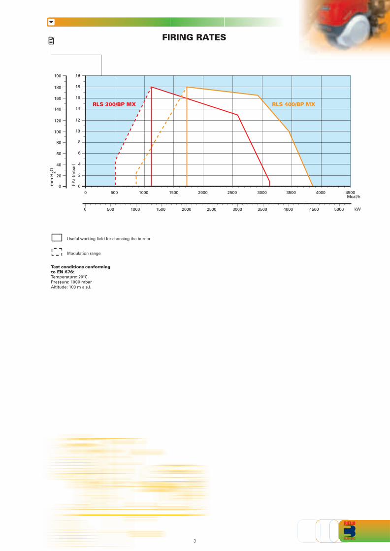
FIRING RATES
Test conditions conformingto EN 676:Temperature: 20°CPressure: 1000 mbarAltitude: 100 m a.s.l.
322
BurnerMonoblock forced draught gas burner with “two stage progressive” or “modulating” operation,fully automatic, made up of:- Fan with reverse curve blades high performance with low sound emissions- Air suction circuit lined with sound-proofing material- Air damper for air setting controlled by a high precision servomotor- Air pressure switch- Fan starting motor at 2800 rpm, three-phase 230/400 - 400/690 V with neutral, 50Hz- Low emission combustion head, that can be set on the basis of required output, fitted with:
- stainless steel end cone, resistant to corrosion and high temperatures- ignition electrodes- flame stability disk
- Maximum gas pressure switch, with pressure test point, for halting the burner in the case of overpressure on the fuel supply line
- Module for air/fuel setting and output modulation with separated PID control of temperature orpressure, available as accessory for RLS/BP MX model
- Flame control panel for controlling the system safety- Ionization probe for flame detector- Star/triangle starter for the fan motor (version with motor electrical power 7,5 kW)- Main electrical supply terminal board- Burner on/off switch- Auxiliary voltage led signal- Burner working led signal- Contacts motor and thermal relay with release button- Motor internal thermal protection- Motor failure led signal- Burner failure led signal and lighted release button- Emergency button- Coded connection plugs-sockets- Burner opening hinge- Lifting rings- IP 54 electric protection level- Gears pump for high pressure fuel supply- Pump starting motor- Oil safety valves- Three oil valves (1st and 2nd stage 3nd safety valve)- Flame control panel- UV photocell for flame detection- Burner on/off selection switch- Oil/Gas selector- Flame inspection window- Burner opening hinge.
Conforming to:- 89/336/EEC directive (electromagnetic compatibility)- 73/23/EEC directive (low voltage)- 90/396/EEC directive (gas)- EN 676 (gas burners).
Standard equipment:- 1 flange gasket- 4 screws for fixing the flange- 1 thermal screen- 4 screws for fixing the burner flange to the boiler- 2 flexible pipes for connection to the oil supply network- 2 nipples for connection to the pump with gaskets.- Instruction handbook for installation, use and maintenance- Spare parts catalogue
PRODUCT SPECIFICATION
Useful working field for choosing the burner
Modulation range
0
4
8
12
10
6
2
14
18
16
00
40
80
120
100
60
20
140
180
160RLS 300/BP MX RLS 400/BP MX
hP
a (m
bar
)
mm
H2O
Mcal/h15001000500 2000 2500 3000 3500 4000 4500
kW500 10000 1500 2000 2500 3000 3500 4000 4500 5000
19190
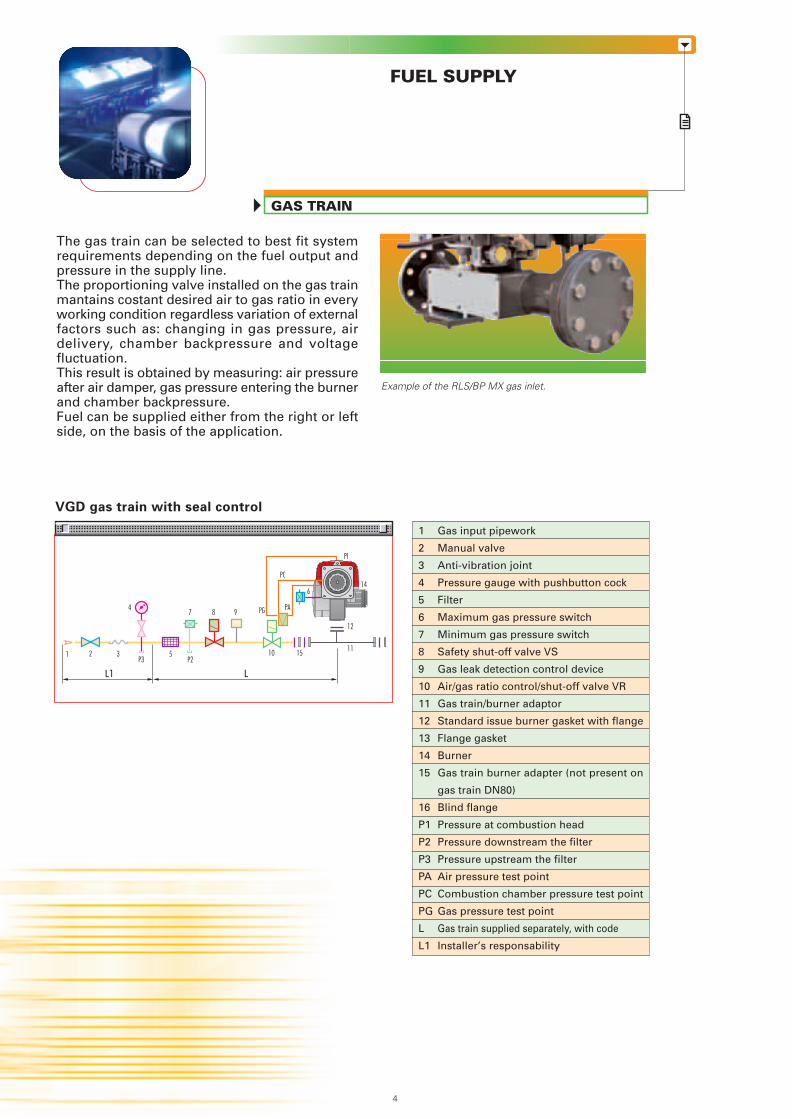
The gas train can be selected to best fit systemrequirements depending on the fuel output andpressure in the supply line.The proportioning valve installed on the gas trainmantains costant desired air to gas ratio in everyworking condition regardless variation of externalfactors such as: changing in gas pressure, airdelivery, chamber backpressure and voltagefluctuation.This result is obtained by measuring: air pressureafter air damper, gas pressure entering the burnerand chamber backpressure.Fuel can be supplied either from the right or leftside, on the basis of the application.
GAS TRAIN
FUEL SUPPLY
VGD gas train with seal control
Gas input pipework
Manual valve
Anti-vibration joint
Pressure gauge with pushbutton cock
Filter
Maximum gas pressure switch
Minimum gas pressure switch
Safety shut-off valve VS
Gas leak detection control device
Air/gas ratio control/shut-off valve VR
Gas train/burner adaptor
Standard issue burner gasket with flange
Flange gasket
Burner
Gas train burner adapter (not present on
gas train DN80)
Blind flange
Pressure at combustion head
Pressure downstream the filter
Pressure upstream the filter
Air pressure test point
Combustion chamber pressure test point
Gas pressure test point
Gas train supplied separately, with code
Installer’s responsability
1
2
3
4
5
6
7
8
9
10
11
12
13
14
15
16
P1
P2
P3
PA
PC
PG
L
L1
Example of the RLS/BP MX gas inlet.
214
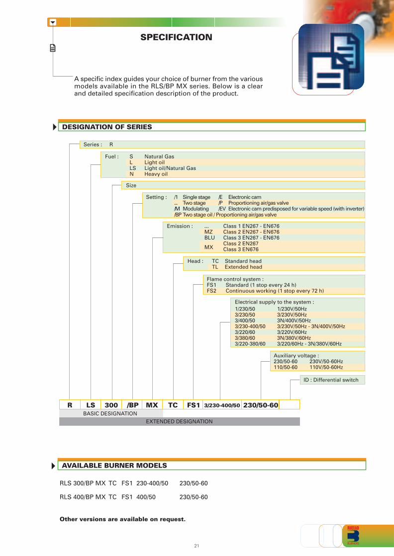
SPECIFICATION
A specific index guides your choice of burner from the variousmodels available in the RLS/BP MX series. Below is a clearand detailed specification description of the product.
DESIGNATION OF SERIES
Size
Fuel : S Natural GasL Light oilLS Light oil/Natural GasN Heavy oil
Series : R
ID : Differential switch
RBASIC DESIGNATION
LS 300 /BP TC FS1 3/230-400/50 230/50-60
EXTENDED DESIGNATION
Emission : ... Class 1 EN267 - EN676MZ Class 2 EN267 - EN676BLU Class 3 EN267 - EN676
MXClass 2 EN267Class 3 EN676
Head : TC Standard headTL Extended head
MX
Auxiliary voltage :230/50-60 230V/50-60Hz110/50-60 110V/50-60Hz
Electrical supply to the system :
Flame control system : FS1 Standard (1 stop every 24 h)FS2 Continuous working (1 stop every 72 h)
Setting : /1 Single stage /E Electronic cam... Two stage /P Proportioning air/gas valve/M Modulating /EV Electronic cam predisposed for variable speed (with inverter)/BP Two stage oil / Proportioning air/gas valve
1/230/50 1/230V/50Hz3/230/50 3/230V/50Hz3/400/50 3N/400V/50Hz3/230-400/50 3/230V/50Hz - 3N/400V/50Hz3/220/60 3/220V/60Hz3/380/60 3N/380V/60Hz3/220-380/60 3/220/60Hz - 3N/380V/60Hz
AVAILABLE BURNER MODELS
Other versions are available on request.
RLS 300/BP MX TC FS1 230-400/50 230/50-60
RLS 400/BP MX TC FS1 400/50 230/50-60
LL1
12
P3
PI
21P2
7 9
3
84
6
10 15
PG
PC
PA
14
511
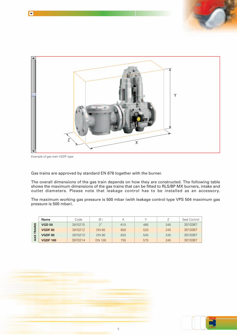
Example of gas train VGDF type
GA
S T
RA
INS
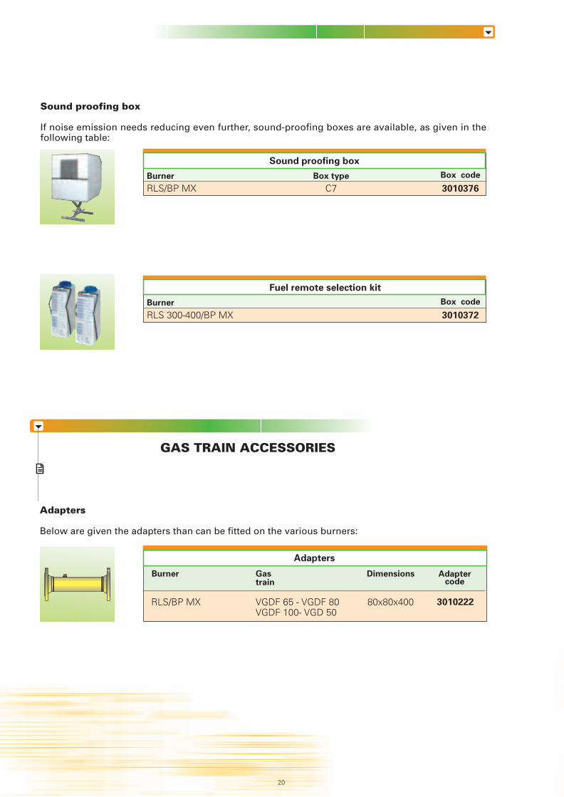
Sound proofing box
If noise emission needs reducing even further, sound-proofing boxes are available, as given in thefollowing table:
GAS TRAIN ACCESSORIES
RLS/BP MX
Adapters
Adaptercode
Name
VGD 50
VGDF 65
VGDF 80
VGDF 100
Code
3970215
3970212
3970213
3970214
Ø i
2”
DN 65
DN 80
DN 100
X
615
600
625
755
Y
495
520
545
575
Z
245
245
245
245
Seal Control
3010367
3010367
3010367
3010367
RLS/BP MXBurner Box code
3010376C7Box type
Sound proofing box
RLS 300-400/BP MXBurner Box code
3010372
Fuel remote selection kit
Gas trains are approved by standard EN 676 together with the burner.
The overall dimensions of the gas train depends on how they are constructed. The following tableshows the maximum dimensions of the gas trains that can be fitted to RLS/BP MX burners, intake andoutlet diameters. Please note that leakage control has to be installed as an accessory.
The maximum working gas pressure is 500 mbar (with leakage control type VPS 504 maximum gaspressure is 500 mbar).
Adapters
Below are given the adapters than can be fitted on the various burners:
Burner Gastrain
3010222
Dimensions
520
VGDF 65 - VGDF 80VGDF 100- VGD 50
80x80x400
Y
ZX
Øi
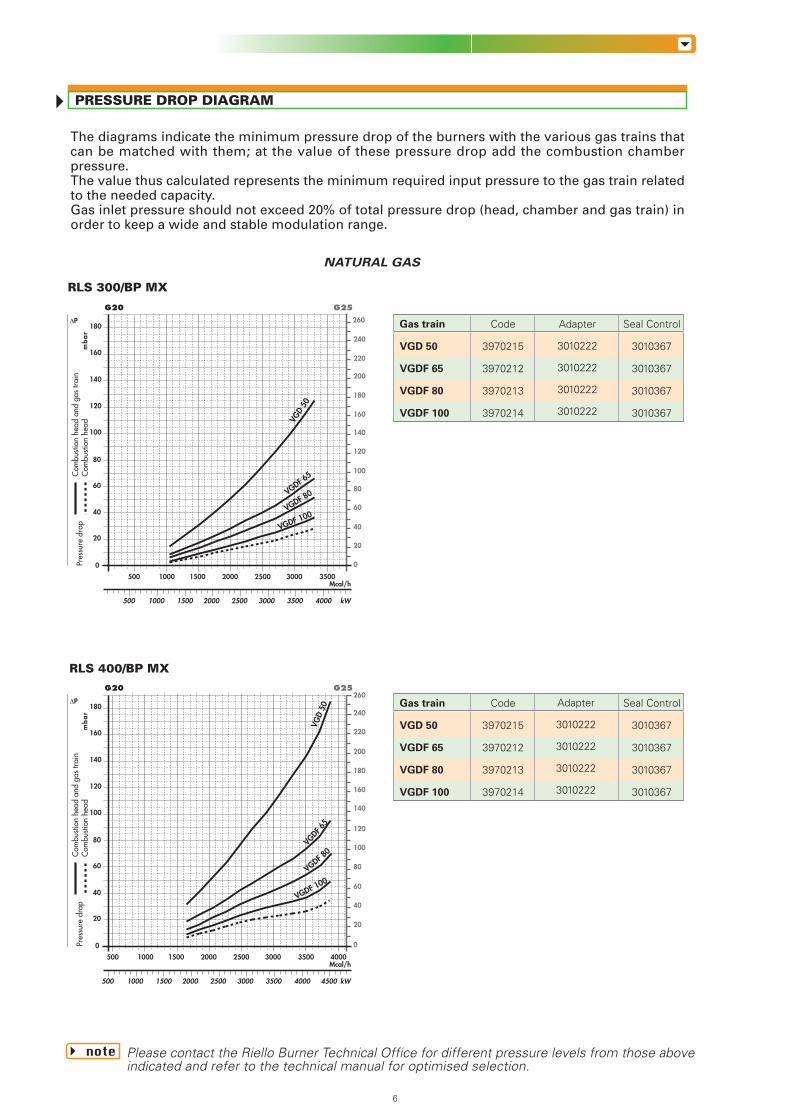
RLS 300/BP MX
PRESSURE DROP DIAGRAM
The diagrams indicate the minimum pressure drop of the burners with the various gas trains thatcan be matched with them; at the value of these pressure drop add the combustion chamberpressure.The value thus calculated represents the minimum required input pressure to the gas train relatedto the needed capacity.Gas inlet pressure should not exceed 20% of total pressure drop (head, chamber and gas train) inorder to keep a wide and stable modulation range.
NATURAL GAS
note Please contact the Riello Burner Technical Office for different pressure levels from those aboveindicated and refer to the technical manual for optimised selection.
Gas train
VGD 50
VGDF 65
VGDF 80
VGDF 100
Code
3970215
3970212
3970213
3970214
Adapter
3010222
3010222
3010222
3010222
Seal Control
3010367
3010367
3010367
3010367
Gas train
VGD 50
VGDF 65
VGDF 80
VGDF 100
Code
3970215
3970212
3970213
3970214
Seal Control
3010367
3010367
3010367
3010367
Adapter
3010222
3010222
3010222
3010222
Mcal/h
20
40
0
mb
ar
G25G20
0
kW
60
80
100
120
140
160
180∆P
Com
busti
on h
ead
and
gas
train
Com
busti
on h
ead
Pres
sure
dro
p
20
40
60
80
100
120
140
160
180
200
220
240
260
2500 350030002000 4000 4500
3000 400035001500 25002000
500 1000 1500
500 1000
Mcal/h
20
40
0
mb
ar
G25G20
0
kW
60
80
100
120
140
160
180∆P
Com
busti
on h
ead
and
gas
train
Com
busti
on h
ead
Pres
sure
dro
p
20
40
60
80
100
120
140
160
180
200
220
240
260
2500 350030002000 4000
3000 35001500 25002000
500 1000 1500
500 1000
VGD
50
VGDF 65
VGDF 80
VGDF 100
VGD
50
VGDF
65
VGDF 80
VGDF 100
196
RLS 400/BP MX
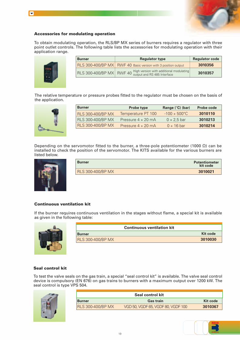
Accessories for modulating operation
To obtain modulating operation, the RLS/BP MX series of burners requires a regulator with threepoint outlet controls. The following table lists the accessories for modulating operation with theirapplication range.
RLS 300-400/BP MX
RLS 300-400/BP MX
RWF 40
Regulator code
3010356
3010357
Burner Regulator type
RWF 40
Basic version with 3 position output
High version with additional modulatingoutput and RS 485 Interface
The relative temperature or pressure probes fitted to the regulator must be chosen on the basis ofthe application.
Continuous ventilation kit
If the burner requires continuous ventilation in the stages without flame, a special kit is availableas given in the following table:
Burner Kit code
Continuous ventilation kit
RLS 300-400/BP MX 3010030
Depending on the servomotor fitted to the burner, a three-pole potentiometer (1000 Ω) can beinstalled to check the position of the servomotor. The KITS available for the various burners arelisted below.
Probe type
Temperature PT 100Pressure 4 ÷ 20 mAPressure 4 ÷ 20 mA
RLS 300-400/BP MXRLS 300-400/BP MXRLS 300-400/BP MX
Burner
RLS 300-400/BP MX
Burner Potentiometerkit code
3010021
Range (°C) (bar)
-100 ÷ 500°C0 ÷ 2,5 bar0 ÷ 16 bar
Probe code
3010110
3010213
3010214
Seal control kit
To test the valve seals on the gas train, a special “seal control kit” is available. The valve seal controldevice is compulsory (EN 676) on gas trains to burners with a maximum output over 1200 kW. Theseal control is type VPS 504.
RLS 300-400/BP MXBurner Kit code
3010367
Seal control kit
Gas train
VGD 50, VGDF 65, VGDF 80, VGDF 100
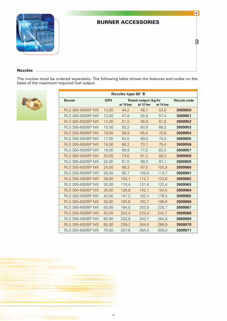
Nozzles
The nozzles must be ordered separately. The following table shows the features and codes on thebasis of the maximum required fuel output.
BURNER ACCESSORIES
0,1 0,2 0,3 0,4 0,5 0,6 0,7 0,8 1 2 3 4 5 106 20
50 60 10080 200 400 800 1000600
3
69
12152230
45 61 76 95 122 152 V1 2 3 4 5 6 7 8 10 20 30 40
1,4
1/2
3/4
1"
1" 1/2
6"
1" 1/4
4"
3"2" 1/22"
PRESSURE DROP (mbar)
PIPE DIAMETER
PIPE LENGTH (m)
Burner GPH Rated output (kg/h) Nozzle code
at 10 bar at 12 bar at 14 bar
RLS 300-400/BP MX 12,00 44,2 48,7 53,0 3009950
RLS 300-400/BP MX 13,00 47,8 52,8 57,4 3009951
RLS 300-400/BP MX 14,00 51,5 56,9 61,8 3009952
RLS 300-400/BP MX 15,00 55,2 60,9 66,2 3009953
RLS 300-400/BP MX 16,00 58,9 65,0 70,6 3009954
RLS 300-400/BP MX 17,00 62,6 69,0 75,0 3009955
RLS 300-400/BP MX 18,00 66,2 73,1 79,4 3009956
RLS 300-400/BP MX 19,00 69,9 77,2 83,5 3009957
RLS 300-400/BP MX 20,00 73,6 81,2 88,3 3009958
RLS 300-400/BP MX 22,00 81,0 89,3 97,1 3009959
RLS 300-400/BP MX 24,00 88,3 97,5 105,9 3009960
RLS 300-400/BP MX 26,00 95,7 105,6 114,7 3009961
RLS 300-400/BP MX 28,00 103,1 113,7 123,6 3009962
RLS 300-400/BP MX 30,00 110,4 121,8 132,4 3009963
RLS 300-400/BP MX 35,00 128,8 142,1 154,5 3009964
RLS 300-400/BP MX 40,00 147,2 162,4 176,5 3009965
RLS 300-400/BP MX 45,00 165,6 182,7 198,6 3009966
RLS 300-400/BP MX 50,00 184,0 203,0 220,7 3009967
RLS 300-400/BP MX 55,00 202,4 223,4 242,7 3009968
RLS 300-400/BP MX 60,00 220,8 243,7 264,8 3009969
RLS 300-400/BP MX 65,00 239,2 264,0 286,9 3009970
RLS 300-400/BP MX 70,00 257,6 284,3 309,0 3009971
= Gas output Nmc/h
f1 - G20
= 0,62 - G251,18 - G31
fV
15,34
718
Figure A
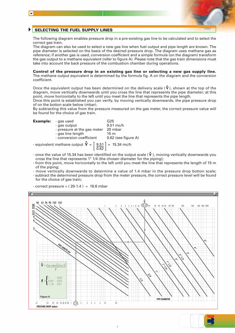
The following diagram enables pressure drop in a pre-existing gas line to be calculated and to select thecorrect gas train.The diagram can also be used to select a new gas line when fuel output and pipe length are known. Thepipe diameter is selected on the basis of the desired pressure drop. The diagram uses methane gas asreference; if another gas is used, conversion coefficient and a simple formula (on the diagram) transformthe gas output to a methane equivalent (refer to figure A). Please note that the gas train dimensions musttake into account the back pressure of the combustion chamber during operations.
Control of the pressure drop in an existing gas line or selecting a new gas supply line.The methane output equivalent is determined by the formula fig. A on the diagram and the conversioncoefficient.
Once the equivalent output has been determined on the delivery scale ( ), shown at the top of thediagram, move vertically downwards until you cross the line that represents the pipe diameter; at thispoint, move horizontally to the left until you meet the line that represents the pipe length.Once this point is established you can verify, by moving vertically downwards, the pipe pressure dropof on the botton scale below (mbar).By subtracting this value from the pressure measured on the gas meter, the correct pressure value willbe found for the choice of gas train.
Example: - gas used G25- gas output 9.51 mc/h- pressure at the gas meter 20 mbar- gas line length 15 m- conversion coefficient 0.62 (see figure A)
- equivalent methane output = 9.51 = 15.34 mc/h0.62
- once the value of 15.34 has been identified on the output scale ( ), moving vertically downwards youcross the line that represents 1" 1/4 (the chosen diameter for the piping);
- from this point, move horizontally to the left until you meet the line that represents the length of 15 mof the piping;
- move vertically downwards to determine a value of 1.4 mbar in the pressure drop botton scale;- subtract the determined pressure drop from the meter pressure, the correct pressure level will be found
for the choice of gas train;
- correct pressure = ( 20-1.4 ) = 18.6 mbar
V
V
V
SELECTING THE FUEL SUPPLY LINES
Nozzles type 60° B
HYDRAULIC CIRCUIT
RLS BP/MX
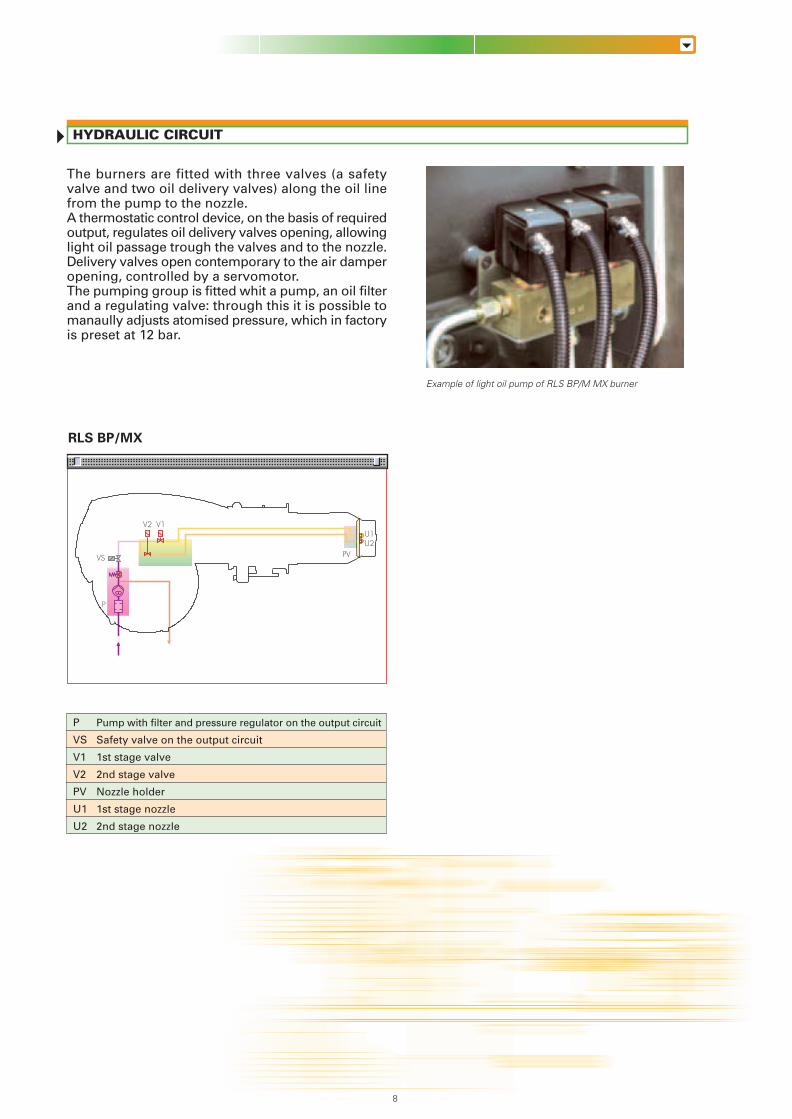
The burners are fitted with three valves (a safetyvalve and two oil delivery valves) along the oil linefrom the pump to the nozzle.A thermostatic control device, on the basis of requiredoutput, regulates oil delivery valves opening, allowinglight oil passage trough the valves and to the nozzle.Delivery valves open contemporary to the air damperopening, controlled by a servomotor.The pumping group is fitted whit a pump, an oil filterand a regulating valve: through this it is possible tomanaully adjusts atomised pressure, which in factoryis preset at 12 bar.
Example of light oil pump of RLS BP/M MX burner
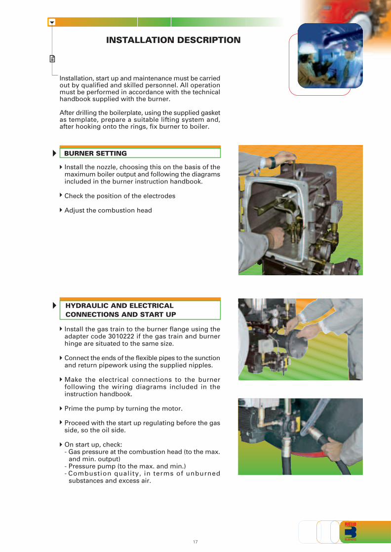
HYDRAULIC AND ELECTRICALCONNECTIONS AND START UP
Install the nozzle, choosing this on the basis of themaximum boiler output and following the diagramsincluded in the burner instruction handbook.
Check the position of the electrodes
Adjust the combustion head
Install the gas train to the burner flange using theadapter code 3010222 if the gas train and burnerhinge are situated to the same size.
Connect the ends of the flexible pipes to the sunctionand return pipework using the supplied nipples.
Make the electrical connections to the burnerfollowing the wiring diagrams included in theinstruction handbook.
Prime the pump by turning the motor.
Proceed with the start up regulating before the gasside, so the oil side.
On start up, check:- Gas pressure at the combustion head (to the max.
and min. output)- Pressure pump (to the max. and min.)- Combustion quality, in terms of unburned
substances and excess air.
INSTALLATION DESCRIPTION
Installation, start up and maintenance must be carriedout by qualified and skilled personnel. All operationmust be performed in accordance with the technicalhandbook supplied with the burner.
After drilling the boilerplate, using the supplied gasketas template, prepare a suitable lifting system and,after hooking onto the rings, fix burner to boiler.
BURNER SETTING
P
VS
V2 V1
PV
U1U2
178
P
VS
V1
V2
PV
U1
U2
Pump with filter and pressure regulator on the output circuit
Safety valve on the output circuit
1st stage valve
2nd stage valve
Nozzle holder
1st stage nozzle
2nd stage nozzle
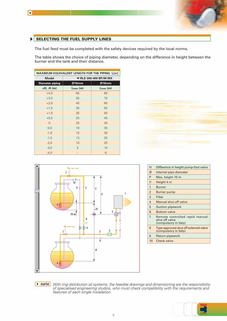
The fuel feed must be completed with the safety devices required by the local norms.
The table shows the choice of piping diameter, depending on the difference in height between theburner and the tank and their distance.
With ring distribution oil systems, the feasible drawings and dimensioning are the responsibilityof specialised engineering studios, who must check compatibility with the requirements andfeatures of each single installation.
Model RLS 300-400 BP/M MX
Diameter piping Ø16mm Ø18mm
+H, -H (m) Lmax (m) Lmax (m)
+4,0 60 80
+3,0 50 70
+2,0 40 60
+1,5 35 55
+1,0 30 50
+0,5 25 45
0 20 40
-0,5 18 35
-1,0 15 30
-1,5 13 25
-2,0 10 20
-3,0 5 10
-4,0 - 6
MAXIMUM EQUIVALENT LENGTH FOR THE PIPING L[m]
Difference in height pump-foot valve
Internal pipe diameter
Max. height 10 m
Height 4 m
Burner
Burner pump
Filter
Manual shut off valve
Suction pipework
Bottom valve
Remote controlled rapid manualshut off valve(compulsory in Italy)
Type approved shut off solenoid valve(compulsory in Italy)
Return pipework
Check valve
H
Ø
P
V
1
2
3
4
5
6
7
8
9
10
note
7
10
9 5 V
P
+H
-H
8
1
4
10 cm2
57 3
9
6
6
X
Z
Y
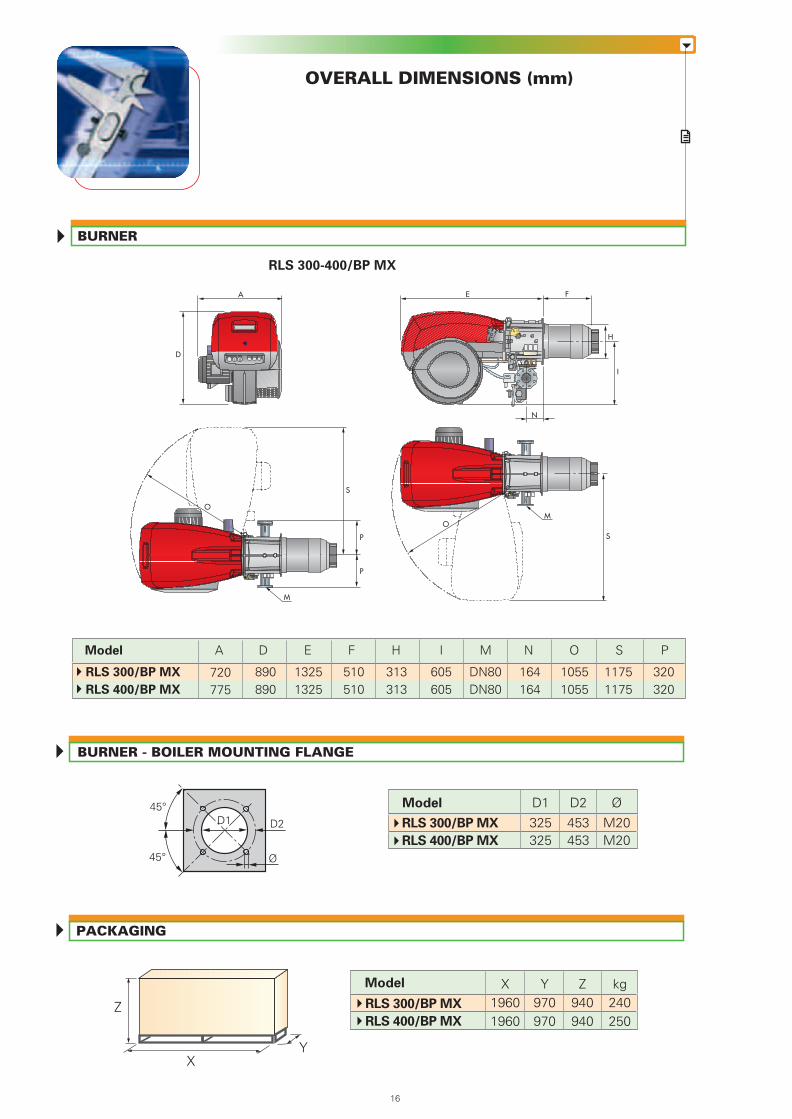
OVERALL DIMENSIONS (mm)
PACKAGING
BURNER - BOILER MOUNTING FLANGE
RLS 300-400/BP MX
BURNER
ØD2325325
M20M20
453453
D1
Ø
D2
45°
45°
D1
Model X19601960
Y970970
kg240250
Z940940
Model
RLS 300/BP MX
RLS 400/BP MX
RLS 300/BP MX
RLS 400/BP MX
M
S
O
M
O
S
P
P
A
D
E
I
F
H
N
916
Model
RLS 300/BP MX
RLS 400/BP MX
F PA D E H I N OM S
720775
510510
320320
890890
13251325
313313
605605
164164
10551055
DN80DN80
11751175
SELECTING THE FUEL SUPPLY LINES
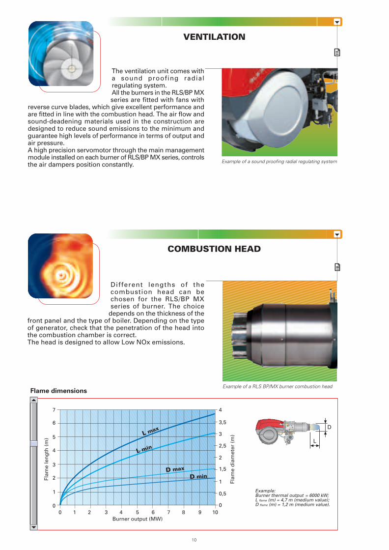
The ventilation unit comes witha sound proofing radialregulating system.All the burners in the RLS/BP MXseries are fitted with fans with
reverse curve blades, which give excellent performance andare fitted in line with the combustion head. The air flow andsound-deadening materials used in the construction aredesigned to reduce sound emissions to the minimum andguarantee high levels of performance in terms of output andair pressure.A high precision servomotor through the main managementmodule installed on each burner of RLS/BP MX series, controlsthe air dampers position constantly.
COMBUSTION HEAD
VENTILATION
Different lengths of thecombustion head can bechosen for the RLS/BP MXseries of burner. The choice
depends on the thickness of thefront panel and the type of boiler. Depending on the typeof generator, check that the penetration of the head intothe combustion chamber is correct.The head is designed to allow Low NOx emissions.
Flame dimensions
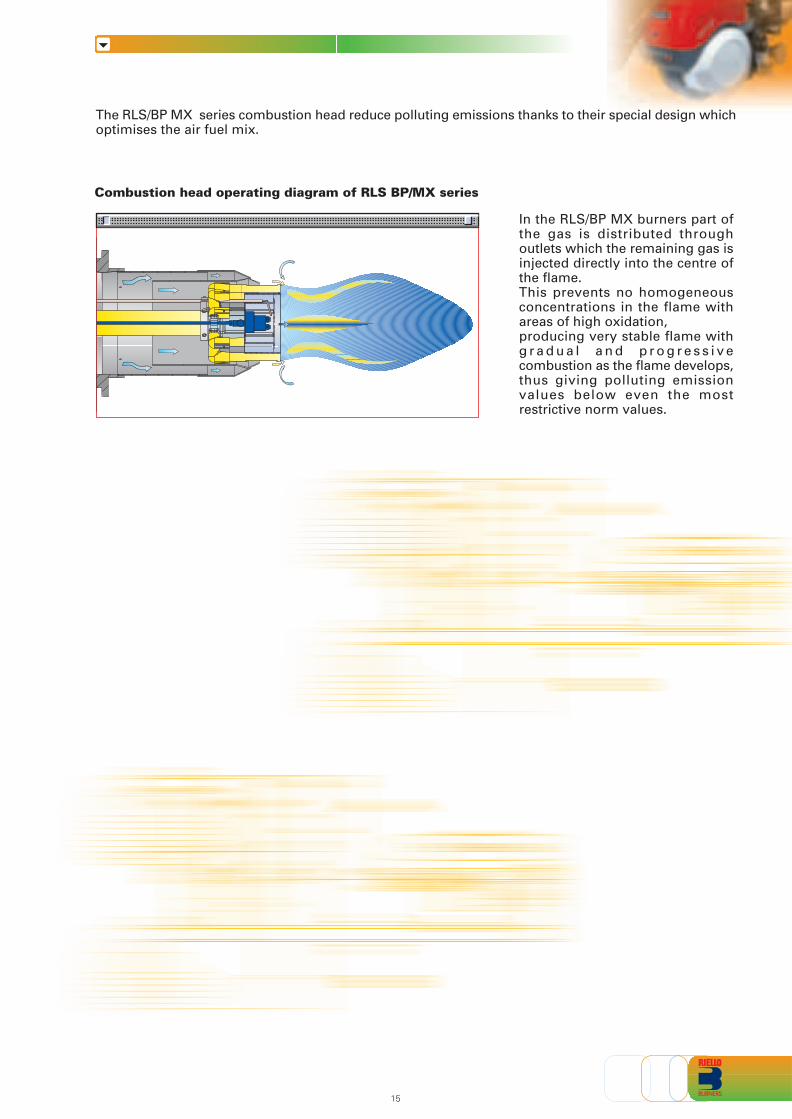
The RLS/BP MX series combustion head reduce polluting emissions thanks to their special design whichoptimises the air fuel mix.
In the RLS/BP MX burners part ofthe gas is distributed throughoutlets which the remaining gas isinjected directly into the centre ofthe flame.This prevents no homogeneousconcentrations in the flame withareas of high oxidation,producing very stable flame withg r a d u a l a n d p r o g r e s s i v ecombustion as the flame develops,thus giving polluting emissionvalues below even the mostrestrictive norm values.
Combustion head operating diagram of RLS BP/MX series
Example:Burner thermal output = 6000 kW;L flame (m) = 4,7 m (medium value);D flame (m) = 1,2 m (medium value).
D
L
Burner output (MW)0 2
3
5
1
1 3
2
4
6
7
4 5 6 7 8 9 10
Flam
e le
ng
th (
m)
Flam
e d
iam
eter
(m
)
0
4
0
0,5
1
1,5
2
2,5
3
3,5
L max
L min
D max
D min
1510
Example of a sound proofing radial regulating system
Example of a RLS BP/MX burner combustion head
ADJUSTMENT
BURNER OPERATION MODE
RLS/BP MX
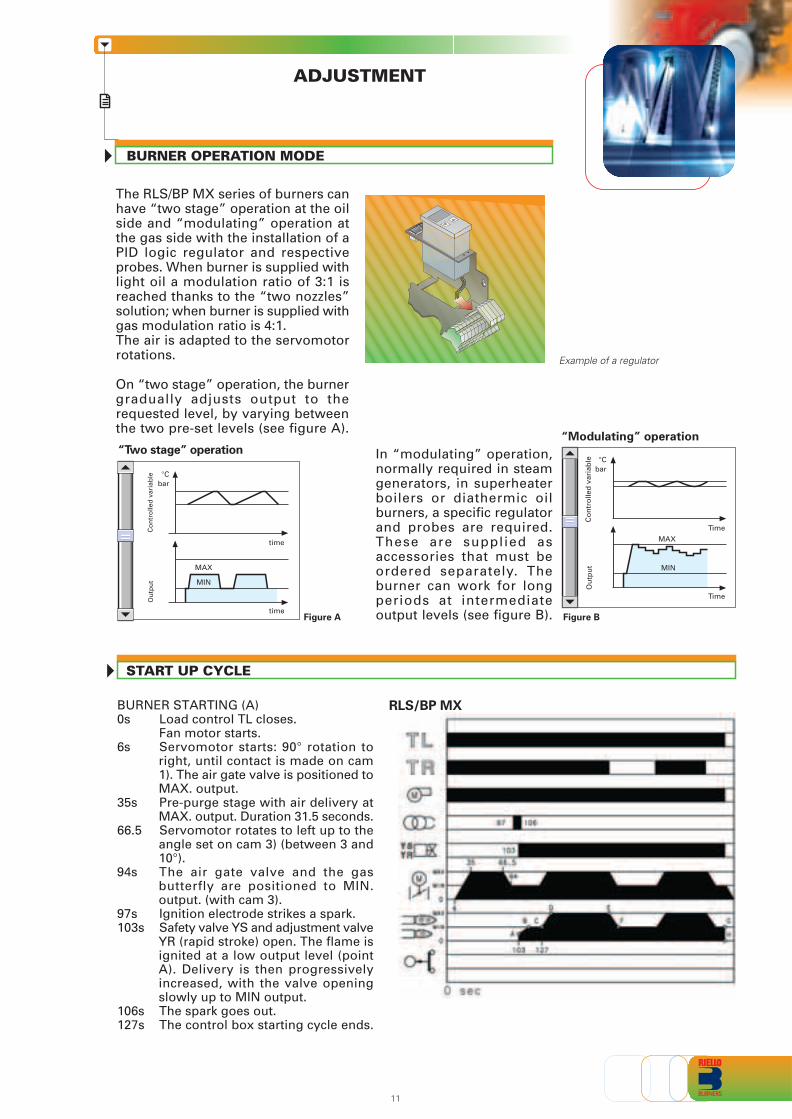
In “modulating” operation,normally required in steamgenerators, in superheaterboilers or diathermic oilburners, a specific regulatorand probes are required.These are supplied asaccessories that must beordered separately. Theburner can work for longperiods at intermediateoutput levels (see figure B).
On “two stage” operation, the burnergradually adjusts output to therequested level, by varying betweenthe two pre-set levels (see figure A).
Figure B
The RLS/BP MX series of burners canhave “two stage” operation at the oilside and “modulating” operation atthe gas side with the installation of aPID logic regulator and respectiveprobes. When burner is supplied withlight oil a modulation ratio of 3:1 isreached thanks to the “two nozzles”solution; when burner is supplied withgas modulation ratio is 4:1.The air is adapted to the servomotorrotations. Example of a regulator
Figure A
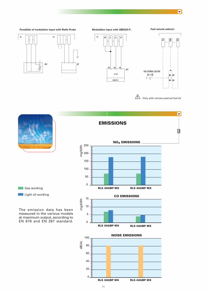
EMISSIONS
The emission data has beenmeasured in the various modelsat maximum output, according toEN 676 and EN 267 standard.
“Modulating” operation“Two stage” operation
Ou
tpu
tC
on
tro
lled
var
iab
le
bar°C
MAX
MIN
time
time
1114
Only with remote external fuel kit
Gas working
Light oil working CO EMISSIONS
mg
/kW
h
0
5
10
15
RLS 300/BP MX RLS 400/BP MX
Fuel remote selector
OIL
COM
GAS
OIL O GAS
FUEL EXTERNAL SELECTOR
NO NO
NO NO
BURNER STARTING (A)0s Load control TL closes.
Fan motor starts.6s Servomotor starts: 90° rotation to
right, until contact is made on cam1). The air gate valve is positioned toMAX. output.
35s Pre-purge stage with air delivery atMAX. output. Duration 31.5 seconds.
66.5 Servomotor rotates to left up to theangle set on cam 3) (between 3 and10°).
94s The air gate valve and the gasbutterfly are positioned to MIN.output. (with cam 3).
97s Ignition electrode strikes a spark.103s Safety valve YS and adjustment valve
YR (rapid stroke) open. The flame isignited at a low output level (pointA). Delivery is then progressivelyincreased, with the valve openingslowly up to MIN output.
106s The spark goes out.127s The control box starting cycle ends.
Ou
tpu
tC
on
tro
lled
var
iab
le
bar°C
MAX
MIN
Time
Time
START UP CYCLE
NOISE EMISSIONS
dB
(A)
0
20
40
60
80
100
RLS 300/BP MX RLS 400/BP MX
NOx EMISSIONS
mg
/kW
h
0
50
100
150
200
250
RLS 300/BP MX RLS 400/BP MX
Modulation input with QBE620-P...
BNWH-BP1
-X1 M1 G- G+ U1
GN
0/10V
QBE620-P...
Possiblity of modulation input with Riello Probe
-BT4 -BP
-X1 -X1
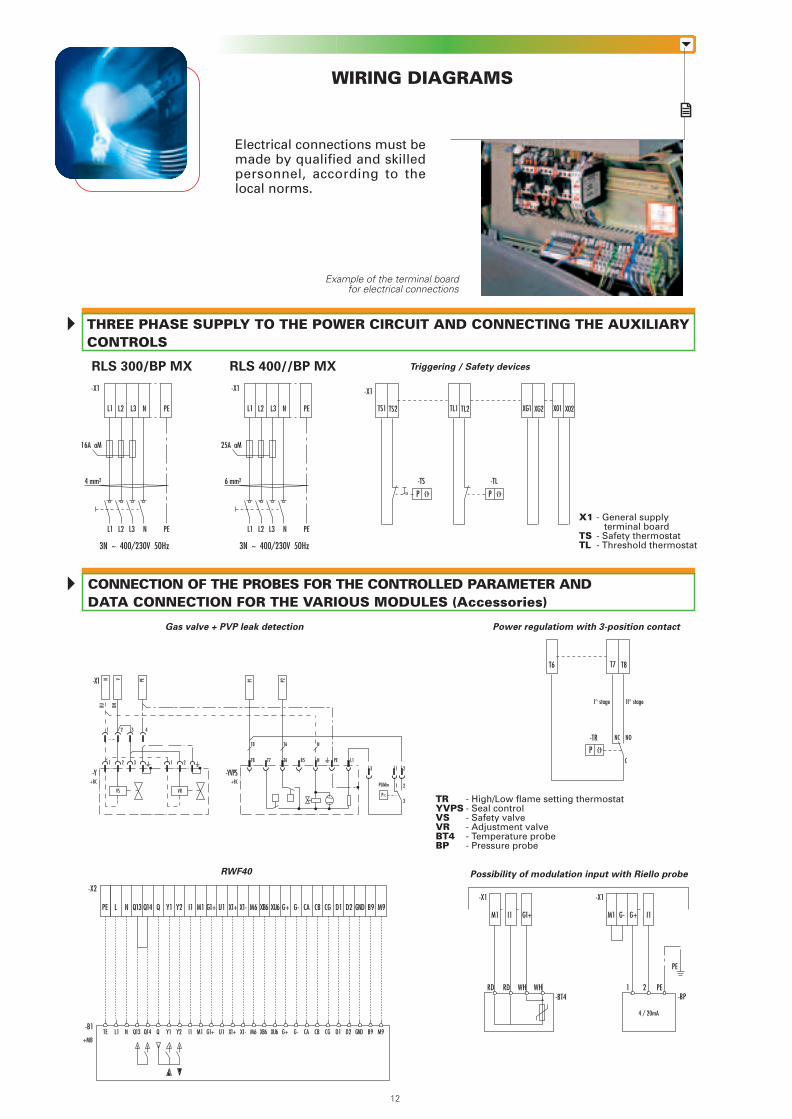
CONNECTION OF THE PROBES FOR THE CONTROLLED PARAMETER ANDDATA CONNECTION FOR THE VARIOUS MODULES (Accessories)
WIRING DIAGRAMS
Electrical connections must bemade by qualified and skilledpersonnel, according to thelocal norms.
Example of the terminal boardfor electrical connections
X1 - General supply terminal board
TS - Safety thermostatTL - Threshold thermostat
RLS 400//BP MX Triggering / Safety devices
Gas valve + PVP leak detection Power regulatiom with 3-position contact
Possibility of modulation input with Riello probeRWF40
THREE PHASE SUPPLY TO THE POWER CIRCUIT AND CONNECTING THE AUXILIARYCONTROLS
RLS 300/BP MX
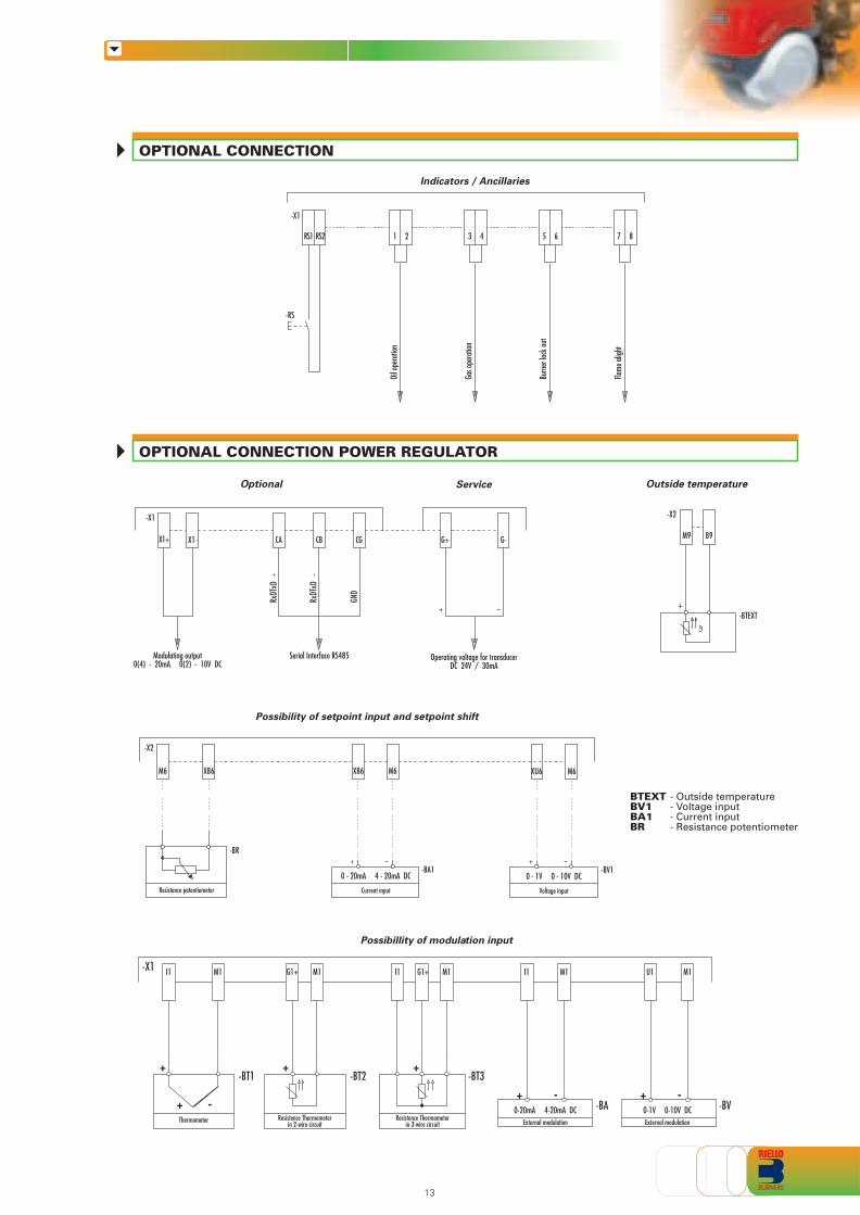
OPTIONAL CONNECTION POWER REGULATOR
OPTIONAL CONNECTION
L1 L2 L3 N PE
-X1
4 mm2
16A aM
L1 L2 L3 N PE
3N ~ 400/230V 50Hz
L1 L2 L3 N PE
-X1
6 mm2
25A aM
L1 L2 L3 N PE
3N ~ 400/230V 50Hz
I1M1 G1+ G+G- I1M1
1 2RD RD WH WH
4 / 20mA
-X1
-TS -TL
TS1 TS2 TL1 TL2 XG1 XG2 X01 X02
P ϑ P ϑ
-TR NC
T6 T7 T8
NO
I° stage II° stage
C
P ϑ
1312
TRYVPSVSVRBT4BP
- High/Low flame setting thermostat- Seal control- Safety valve- Adjustment valve- Temperature probe- Pressure probe
-X1
PE
PE-BT4 -BP
-X1
-X1
21 43
21 3
N V PE P1 P2
BU BN
-Y+BC
VS VR
21
-YVPS+BC
P<
T8
T8
T6
T6
T7 N
N
B5 L1PE
3 1 2
1 2
3
PGMin
BTEXTBV1BA1BR
- Outside temperature- Voltage input- Current input- Resistance potentiometer
Q13 Q14 Q I1 M1 G1+ U1 X1+ X1- M6 XB6 XU6 G+ G- CA CB CG D1 D2 GND B9 M9
Q13 Q14 Q I1 M1 G1+ U1 X1+ X1- M6 XB6 XU6 G+ G- CA CB CG D1 D2 GND B9 M9
-X2
-B1
+MB
NLPE Y1 Y2
NL1TE Y1 Y2
Indicators / Ancillaries
RS2RS1 32 41
Oil o
pera
tion
76 85
Gas o
pera
tion
Burn
er lo
ck ou
t
Flame
aligh
t
-X1
-RS
Outside temperature
B9M9
-X2
-BTEXT
Optional Service
X1-X1+
RxDT
xD
RxDT
xD
GND
CA CB CG G+ G-
Modulating output0(4) - 20mA 0(2) - 10V DC
Serial Interface RS485 Operating voltage for transducerDC 24V / 30mA
-X1
Possibility of setpoint input and setpoint shift
XB6M6
0 - 20mA 4 - 20mA DC
Resistance potentiometer
XB6 M6
Current input
0 - 1V 0 - 10V DC
XU6 M6
Voltage input
-X2
-BR
-BA1 -BV1
Possibillity of modulation input
0-20mA 4-20mA DCExternal modulation
0-1V 0-10V DCExternal modulation
Resistence Thermometerin 3-wire circuit
Resistence Thermometerin 2-wire circuit
Thermometer
M1I1 G1+ M1 M1I1 G1+ M1I1 M1U1-X1
+
+ -
+ +
+ - + -
-BT1 -BT2 -BT3
-BV-BA
CONNECTION OF THE PROBES FOR THE CONTROLLED PARAMETER ANDDATA CONNECTION FOR THE VARIOUS MODULES (Accessories)
WIRING DIAGRAMS
Electrical connections must bemade by qualified and skilledpersonnel, according to thelocal norms.
Example of the terminal boardfor electrical connections
X1 - General supply terminal board
TS - Safety thermostatTL - Threshold thermostat
RLS 400//BP MX Triggering / Safety devices
Gas valve + PVP leak detection Power regulatiom with 3-position contact
Possibility of modulation input with Riello probeRWF40
THREE PHASE SUPPLY TO THE POWER CIRCUIT AND CONNECTING THE AUXILIARYCONTROLS
RLS 300/BP MX
OPTIONAL CONNECTION POWER REGULATOR
OPTIONAL CONNECTION
L1 L2 L3 N PE
-X1
4 mm2
16A aM
L1 L2 L3 N PE
3N ~ 400/230V 50Hz
L1 L2 L3 N PE
-X1
6 mm2
25A aM
L1 L2 L3 N PE
3N ~ 400/230V 50Hz
I1M1 G1+ G+G- I1M1
1 2RD RD WH WH
4 / 20mA
-X1
-TS -TL
TS1 TS2 TL1 TL2 XG1 XG2 X01 X02
P ϑ P ϑ
-TR NC
T6 T7 T8
NO
I° stage II° stage
C
P ϑ
1312
TRYVPSVSVRBT4BP
- High/Low flame setting thermostat- Seal control- Safety valve- Adjustment valve- Temperature probe- Pressure probe
-X1
PE
PE-BT4 -BP
-X1
-X1
21 43
21 3
N V PE P1 P2
BU BN
-Y+BC
VS VR
21
-YVPS+BC
P<
T8
T8
T6
T6
T7 N
N
B5 L1PE
3 1 2
1 2
3
PGMin
BTEXTBV1BA1BR
- Outside temperature- Voltage input- Current input- Resistance potentiometer
Q13 Q14 Q I1 M1 G1+ U1 X1+ X1- M6 XB6 XU6 G+ G- CA CB CG D1 D2 GND B9 M9
Q13 Q14 Q I1 M1 G1+ U1 X1+ X1- M6 XB6 XU6 G+ G- CA CB CG D1 D2 GND B9 M9
-X2
-B1
+MB
NLPE Y1 Y2
NL1TE Y1 Y2
Indicators / Ancillaries
RS2RS1 32 41
Oil o
pera
tion
76 85
Gas o
pera
tion
Burn
er lo
ck ou
t
Flame
aligh
t
-X1
-RS
Outside temperature
B9M9
-X2
-BTEXT
Optional Service
X1-X1+
RxDT
xD
RxDT
xD
GND
CA CB CG G+ G-
Modulating output0(4) - 20mA 0(2) - 10V DC
Serial Interface RS485 Operating voltage for transducerDC 24V / 30mA
-X1
Possibility of setpoint input and setpoint shift
XB6M6
0 - 20mA 4 - 20mA DC
Resistance potentiometer
XB6 M6
Current input
0 - 1V 0 - 10V DC
XU6 M6
Voltage input
-X2
-BR
-BA1 -BV1
Possibillity of modulation input
0-20mA 4-20mA DCExternal modulation
0-1V 0-10V DCExternal modulation
Resistence Thermometerin 3-wire circuit
Resistence Thermometerin 2-wire circuit
Thermometer
M1I1 G1+ M1 M1I1 G1+ M1I1 M1U1-X1
+
+ -
+ +
+ - + -
-BT1 -BT2 -BT3
-BV-BA
ADJUSTMENT
BURNER OPERATION MODE
RLS/BP MX
In “modulating” operation,normally required in steamgenerators, in superheaterboilers or diathermic oilburners, a specific regulatorand probes are required.These are supplied asaccessories that must beordered separately. Theburner can work for longperiods at intermediateoutput levels (see figure B).
On “two stage” operation, the burnergradually adjusts output to therequested level, by varying betweenthe two pre-set levels (see figure A).
Figure B
The RLS/BP MX series of burners canhave “two stage” operation at the oilside and “modulating” operation atthe gas side with the installation of aPID logic regulator and respectiveprobes. When burner is supplied withlight oil a modulation ratio of 3:1 isreached thanks to the “two nozzles”solution; when burner is supplied withgas modulation ratio is 4:1.The air is adapted to the servomotorrotations. Example of a regulator
Figure A
EMISSIONS
The emission data has beenmeasured in the various modelsat maximum output, according toEN 676 and EN 267 standard.
“Modulating” operation“Two stage” operation
Ou
tpu
tC
on
tro
lled
var
iab
le
bar°C
MAX
MIN
time
time
1114
Only with remote external fuel kit
Gas working
Light oil working CO EMISSIONS
mg
/kW
h
0
5
10
15
RLS 300/BP MX RLS 400/BP MX
Fuel remote selector
OIL
COM
GAS
OIL O GAS
FUEL EXTERNAL SELECTOR
NO NO
NO NO
BURNER STARTING (A)0s Load control TL closes.
Fan motor starts.6s Servomotor starts: 90° rotation to
right, until contact is made on cam1). The air gate valve is positioned toMAX. output.
35s Pre-purge stage with air delivery atMAX. output. Duration 31.5 seconds.
66.5 Servomotor rotates to left up to theangle set on cam 3) (between 3 and10°).
94s The air gate valve and the gasbutterfly are positioned to MIN.output. (with cam 3).
97s Ignition electrode strikes a spark.103s Safety valve YS and adjustment valve
YR (rapid stroke) open. The flame isignited at a low output level (pointA). Delivery is then progressivelyincreased, with the valve openingslowly up to MIN output.
106s The spark goes out.127s The control box starting cycle ends.
Ou
tpu
tC
on
tro
lled
var
iab
le
bar°C
MAX
MIN
Time
Time
START UP CYCLE
NOISE EMISSIONS
dB
(A)
0
20
40
60
80
100
RLS 300/BP MX RLS 400/BP MX
NOx EMISSIONS
mg
/kW
h
0
50
100
150
200
250
RLS 300/BP MX RLS 400/BP MX
Modulation input with QBE620-P...
BNWH-BP1
-X1 M1 G- G+ U1
GN
0/10V
QBE620-P...
Possiblity of modulation input with Riello Probe
-BT4 -BP
-X1 -X1
The ventilation unit comes witha sound proofing radialregulating system.All the burners in the RLS/BP MXseries are fitted with fans with
reverse curve blades, which give excellent performance andare fitted in line with the combustion head. The air flow andsound-deadening materials used in the construction aredesigned to reduce sound emissions to the minimum andguarantee high levels of performance in terms of output andair pressure.A high precision servomotor through the main managementmodule installed on each burner of RLS/BP MX series, controlsthe air dampers position constantly.
COMBUSTION HEAD
VENTILATION
Different lengths of thecombustion head can bechosen for the RLS/BP MXseries of burner. The choice
depends on the thickness of thefront panel and the type of boiler. Depending on the typeof generator, check that the penetration of the head intothe combustion chamber is correct.The head is designed to allow Low NOx emissions.
Flame dimensions
The RLS/BP MX series combustion head reduce polluting emissions thanks to their special design whichoptimises the air fuel mix.
In the RLS/BP MX burners part ofthe gas is distributed throughoutlets which the remaining gas isinjected directly into the centre ofthe flame.This prevents no homogeneousconcentrations in the flame withareas of high oxidation,producing very stable flame withg r a d u a l a n d p r o g r e s s i v ecombustion as the flame develops,thus giving polluting emissionvalues below even the mostrestrictive norm values.
Combustion head operating diagram of RLS BP/MX series
Example:Burner thermal output = 6000 kW;L flame (m) = 4,7 m (medium value);D flame (m) = 1,2 m (medium value).
D
L
Burner output (MW)0 2
3
5
1
1 3
2
4
6
7
4 5 6 7 8 9 10
Flam
e le
ng
th (
m)
Flam
e d
iam
eter
(m
)
0
4
0
0,5
1
1,5
2
2,5
3
3,5
L max
L min
D max
D min
1510
Example of a sound proofing radial regulating system
Example of a RLS BP/MX burner combustion head
The fuel feed must be completed with the safety devices required by the local norms.
The table shows the choice of piping diameter, depending on the difference in height between theburner and the tank and their distance.
With ring distribution oil systems, the feasible drawings and dimensioning are the responsibilityof specialised engineering studios, who must check compatibility with the requirements andfeatures of each single installation.
Model RLS 300-400 BP/M MX
Diameter piping Ø16mm Ø18mm
+H, -H (m) Lmax (m) Lmax (m)
+4,0 60 80
+3,0 50 70
+2,0 40 60
+1,5 35 55
+1,0 30 50
+0,5 25 45
0 20 40
-0,5 18 35
-1,0 15 30
-1,5 13 25
-2,0 10 20
-3,0 5 10
-4,0 - 6
MAXIMUM EQUIVALENT LENGTH FOR THE PIPING L[m]
Difference in height pump-foot valve
Internal pipe diameter
Max. height 10 m
Height 4 m
Burner
Burner pump
Filter
Manual shut off valve
Suction pipework
Bottom valve
Remote controlled rapid manualshut off valve(compulsory in Italy)
Type approved shut off solenoid valve(compulsory in Italy)
Return pipework
Check valve
H
Ø
P
V
1
2
3
4
5
6
7
8
9
10
note
7
10
9 5 V
P
+H
-H
8
1
4
10 cm2
57 3
9
6
6
X
Z
Y
OVERALL DIMENSIONS (mm)
PACKAGING
BURNER - BOILER MOUNTING FLANGE
RLS 300-400/BP MX
BURNER
ØD2325325
M20M20
453453
D1
Ø
D2
45°
45°
D1
Model X19601960
Y970970
kg240250
Z940940
Model
RLS 300/BP MX
RLS 400/BP MX
RLS 300/BP MX
RLS 400/BP MX
M
S
O
M
O
S
P
P
A
D
E
I
F
H
N
916
Model
RLS 300/BP MX
RLS 400/BP MX
F PA D E H I N OM S
720775
510510
320320
890890
13251325
313313
605605
164164
10551055
DN80DN80
11751175
SELECTING THE FUEL SUPPLY LINES
HYDRAULIC CIRCUIT
RLS BP/MX
The burners are fitted with three valves (a safetyvalve and two oil delivery valves) along the oil linefrom the pump to the nozzle.A thermostatic control device, on the basis of requiredoutput, regulates oil delivery valves opening, allowinglight oil passage trough the valves and to the nozzle.Delivery valves open contemporary to the air damperopening, controlled by a servomotor.The pumping group is fitted whit a pump, an oil filterand a regulating valve: through this it is possible tomanaully adjusts atomised pressure, which in factoryis preset at 12 bar.
Example of light oil pump of RLS BP/M MX burner
HYDRAULIC AND ELECTRICALCONNECTIONS AND START UP
Install the nozzle, choosing this on the basis of themaximum boiler output and following the diagramsincluded in the burner instruction handbook.
Check the position of the electrodes
Adjust the combustion head
Install the gas train to the burner flange using theadapter code 3010222 if the gas train and burnerhinge are situated to the same size.
Connect the ends of the flexible pipes to the sunctionand return pipework using the supplied nipples.
Make the electrical connections to the burnerfollowing the wiring diagrams included in theinstruction handbook.
Prime the pump by turning the motor.
Proceed with the start up regulating before the gasside, so the oil side.
On start up, check:- Gas pressure at the combustion head (to the max.
and min. output)- Pressure pump (to the max. and min.)- Combustion quality, in terms of unburned
substances and excess air.
INSTALLATION DESCRIPTION
Installation, start up and maintenance must be carriedout by qualified and skilled personnel. All operationmust be performed in accordance with the technicalhandbook supplied with the burner.
After drilling the boilerplate, using the supplied gasketas template, prepare a suitable lifting system and,after hooking onto the rings, fix burner to boiler.
BURNER SETTING
P
VS
V2 V1
PV
U1U2
178
P
VS
V1
V2
PV
U1
U2
Pump with filter and pressure regulator on the output circuit
Safety valve on the output circuit
1st stage valve
2nd stage valve
Nozzle holder
1st stage nozzle
2nd stage nozzle
Nozzles
The nozzles must be ordered separately. The following table shows the features and codes on thebasis of the maximum required fuel output.
BURNER ACCESSORIES
0,1 0,2 0,3 0,4 0,5 0,6 0,7 0,8 1 2 3 4 5 106 20
50 60 10080 200 400 800 1000600
3
69
12152230
45 61 76 95 122 152 V1 2 3 4 5 6 7 8 10 20 30 40
1,4
1/2
3/4
1"
1" 1/2
6"
1" 1/4
4"
3"2" 1/22"
PRESSURE DROP (mbar)
PIPE DIAMETER
PIPE LENGTH (m)
Burner GPH Rated output (kg/h) Nozzle code
at 10 bar at 12 bar at 14 bar
RLS 300-400/BP MX 12,00 44,2 48,7 53,0 3009950
RLS 300-400/BP MX 13,00 47,8 52,8 57,4 3009951
RLS 300-400/BP MX 14,00 51,5 56,9 61,8 3009952
RLS 300-400/BP MX 15,00 55,2 60,9 66,2 3009953
RLS 300-400/BP MX 16,00 58,9 65,0 70,6 3009954
RLS 300-400/BP MX 17,00 62,6 69,0 75,0 3009955
RLS 300-400/BP MX 18,00 66,2 73,1 79,4 3009956
RLS 300-400/BP MX 19,00 69,9 77,2 83,5 3009957
RLS 300-400/BP MX 20,00 73,6 81,2 88,3 3009958
RLS 300-400/BP MX 22,00 81,0 89,3 97,1 3009959
RLS 300-400/BP MX 24,00 88,3 97,5 105,9 3009960
RLS 300-400/BP MX 26,00 95,7 105,6 114,7 3009961
RLS 300-400/BP MX 28,00 103,1 113,7 123,6 3009962
RLS 300-400/BP MX 30,00 110,4 121,8 132,4 3009963
RLS 300-400/BP MX 35,00 128,8 142,1 154,5 3009964
RLS 300-400/BP MX 40,00 147,2 162,4 176,5 3009965
RLS 300-400/BP MX 45,00 165,6 182,7 198,6 3009966
RLS 300-400/BP MX 50,00 184,0 203,0 220,7 3009967
RLS 300-400/BP MX 55,00 202,4 223,4 242,7 3009968
RLS 300-400/BP MX 60,00 220,8 243,7 264,8 3009969
RLS 300-400/BP MX 65,00 239,2 264,0 286,9 3009970
RLS 300-400/BP MX 70,00 257,6 284,3 309,0 3009971
= Gas output Nmc/h
f1 - G20
= 0,62 - G251,18 - G31
fV
15,34
718
Figure A
The following diagram enables pressure drop in a pre-existing gas line to be calculated and to select thecorrect gas train.The diagram can also be used to select a new gas line when fuel output and pipe length are known. Thepipe diameter is selected on the basis of the desired pressure drop. The diagram uses methane gas asreference; if another gas is used, conversion coefficient and a simple formula (on the diagram) transformthe gas output to a methane equivalent (refer to figure A). Please note that the gas train dimensions musttake into account the back pressure of the combustion chamber during operations.
Control of the pressure drop in an existing gas line or selecting a new gas supply line.The methane output equivalent is determined by the formula fig. A on the diagram and the conversioncoefficient.
Once the equivalent output has been determined on the delivery scale ( ), shown at the top of thediagram, move vertically downwards until you cross the line that represents the pipe diameter; at thispoint, move horizontally to the left until you meet the line that represents the pipe length.Once this point is established you can verify, by moving vertically downwards, the pipe pressure dropof on the botton scale below (mbar).By subtracting this value from the pressure measured on the gas meter, the correct pressure value willbe found for the choice of gas train.
Example: - gas used G25- gas output 9.51 mc/h- pressure at the gas meter 20 mbar- gas line length 15 m- conversion coefficient 0.62 (see figure A)
- equivalent methane output = 9.51 = 15.34 mc/h0.62
- once the value of 15.34 has been identified on the output scale ( ), moving vertically downwards youcross the line that represents 1" 1/4 (the chosen diameter for the piping);
- from this point, move horizontally to the left until you meet the line that represents the length of 15 mof the piping;
- move vertically downwards to determine a value of 1.4 mbar in the pressure drop botton scale;- subtract the determined pressure drop from the meter pressure, the correct pressure level will be found
for the choice of gas train;
- correct pressure = ( 20-1.4 ) = 18.6 mbar
V
V
V
SELECTING THE FUEL SUPPLY LINES
Nozzles type 60° B
RLS 300/BP MX
PRESSURE DROP DIAGRAM
The diagrams indicate the minimum pressure drop of the burners with the various gas trains thatcan be matched with them; at the value of these pressure drop add the combustion chamberpressure.The value thus calculated represents the minimum required input pressure to the gas train relatedto the needed capacity.Gas inlet pressure should not exceed 20% of total pressure drop (head, chamber and gas train) inorder to keep a wide and stable modulation range.
NATURAL GAS
note Please contact the Riello Burner Technical Office for different pressure levels from those aboveindicated and refer to the technical manual for optimised selection.
Gas train
VGD 50
VGDF 65
VGDF 80
VGDF 100
Code
3970215
3970212
3970213
3970214
Adapter
3010222
3010222
3010222
3010222
Seal Control
3010367
3010367
3010367
3010367
Gas train
VGD 50
VGDF 65
VGDF 80
VGDF 100
Code
3970215
3970212
3970213
3970214
Seal Control
3010367
3010367
3010367
3010367
Adapter
3010222
3010222
3010222
3010222
Mcal/h
20
40
0
mb
ar
G25G20
0
kW
60
80
100
120
140
160
180∆P
Com
busti
on h
ead
and
gas
train
Com
busti
on h
ead
Pres
sure
dro
p
20
40
60
80
100
120
140
160
180
200
220
240
260
2500 350030002000 4000 4500
3000 400035001500 25002000
500 1000 1500
500 1000
Mcal/h
20
40
0
mb
ar
G25G20
0
kW
60
80
100
120
140
160
180∆P
Com
busti
on h
ead
and
gas
train
Com
busti
on h
ead
Pres
sure
dro
p
20
40
60
80
100
120
140
160
180
200
220
240
260
2500 350030002000 4000
3000 35001500 25002000
500 1000 1500
500 1000
VGD
50
VGDF 65
VGDF 80
VGDF 100
VGD
50
VGDF
65
VGDF 80
VGDF 100
196
RLS 400/BP MX
Accessories for modulating operation
To obtain modulating operation, the RLS/BP MX series of burners requires a regulator with threepoint outlet controls. The following table lists the accessories for modulating operation with theirapplication range.
RLS 300-400/BP MX
RLS 300-400/BP MX
RWF 40
Regulator code
3010356
3010357
Burner Regulator type
RWF 40
Basic version with 3 position output
High version with additional modulatingoutput and RS 485 Interface
The relative temperature or pressure probes fitted to the regulator must be chosen on the basis ofthe application.
Continuous ventilation kit
If the burner requires continuous ventilation in the stages without flame, a special kit is availableas given in the following table:
Burner Kit code
Continuous ventilation kit
RLS 300-400/BP MX 3010030
Depending on the servomotor fitted to the burner, a three-pole potentiometer (1000 Ω) can beinstalled to check the position of the servomotor. The KITS available for the various burners arelisted below.
Probe type
Temperature PT 100Pressure 4 ÷ 20 mAPressure 4 ÷ 20 mA
RLS 300-400/BP MXRLS 300-400/BP MXRLS 300-400/BP MX
Burner
RLS 300-400/BP MX
Burner Potentiometerkit code
3010021
Range (°C) (bar)
-100 ÷ 500°C0 ÷ 2,5 bar0 ÷ 16 bar
Probe code
3010110
3010213
3010214
Seal control kit
To test the valve seals on the gas train, a special “seal control kit” is available. The valve seal controldevice is compulsory (EN 676) on gas trains to burners with a maximum output over 1200 kW. Theseal control is type VPS 504.
RLS 300-400/BP MXBurner Kit code
3010367
Seal control kit
Gas train
VGD 50, VGDF 65, VGDF 80, VGDF 100
Example of gas train VGDF type
GA
S T
RA
INS
Sound proofing box
If noise emission needs reducing even further, sound-proofing boxes are available, as given in thefollowing table:
GAS TRAIN ACCESSORIES
RLS/BP MX
Adapters
Adaptercode
Name
VGD 50
VGDF 65
VGDF 80
VGDF 100
Code
3970215
3970212
3970213
3970214
Ø i
2”
DN 65
DN 80
DN 100
X
615
600
625
755
Y
495
520
545
575
Z
245
245
245
245
Seal Control
3010367
3010367
3010367
3010367
RLS/BP MXBurner Box code
3010376C7Box type
Sound proofing box
RLS 300-400/BP MXBurner Box code
3010372
Fuel remote selection kit
Gas trains are approved by standard EN 676 together with the burner.
The overall dimensions of the gas train depends on how they are constructed. The following tableshows the maximum dimensions of the gas trains that can be fitted to RLS/BP MX burners, intake andoutlet diameters. Please note that leakage control has to be installed as an accessory.
The maximum working gas pressure is 500 mbar (with leakage control type VPS 504 maximum gaspressure is 500 mbar).
Adapters
Below are given the adapters than can be fitted on the various burners:
Burner Gastrain
3010222
Dimensions
520
VGDF 65 - VGDF 80VGDF 100- VGD 50
80x80x400
Y
ZX
Øi
The gas train can be selected to best fit systemrequirements depending on the fuel output andpressure in the supply line.The proportioning valve installed on the gas trainmantains costant desired air to gas ratio in everyworking condition regardless variation of externalfactors such as: changing in gas pressure, airdelivery, chamber backpressure and voltagefluctuation.This result is obtained by measuring: air pressureafter air damper, gas pressure entering the burnerand chamber backpressure.Fuel can be supplied either from the right or leftside, on the basis of the application.
GAS TRAIN
FUEL SUPPLY
VGD gas train with seal control
Gas input pipework
Manual valve
Anti-vibration joint
Pressure gauge with pushbutton cock
Filter
Maximum gas pressure switch
Minimum gas pressure switch
Safety shut-off valve VS
Gas leak detection control device
Air/gas ratio control/shut-off valve VR
Gas train/burner adaptor
Standard issue burner gasket with flange
Flange gasket
Burner
Gas train burner adapter (not present on
gas train DN80)
Blind flange
Pressure at combustion head
Pressure downstream the filter
Pressure upstream the filter
Air pressure test point
Combustion chamber pressure test point
Gas pressure test point
Gas train supplied separately, with code
Installer’s responsability
1
2
3
4
5
6
7
8
9
10
11
12
13
14
15
16
P1
P2
P3
PA
PC
PG
L
L1
Example of the RLS/BP MX gas inlet.
214
SPECIFICATION
A specific index guides your choice of burner from the variousmodels available in the RLS/BP MX series. Below is a clearand detailed specification description of the product.
DESIGNATION OF SERIES
Size
Fuel : S Natural GasL Light oilLS Light oil/Natural GasN Heavy oil
Series : R
ID : Differential switch
RBASIC DESIGNATION
LS 300 /BP TC FS1 3/230-400/50 230/50-60
EXTENDED DESIGNATION
Emission : ... Class 1 EN267 - EN676MZ Class 2 EN267 - EN676BLU Class 3 EN267 - EN676
MXClass 2 EN267Class 3 EN676
Head : TC Standard headTL Extended head
MX
Auxiliary voltage :230/50-60 230V/50-60Hz110/50-60 110V/50-60Hz
Electrical supply to the system :
Flame control system : FS1 Standard (1 stop every 24 h)FS2 Continuous working (1 stop every 72 h)
Setting : /1 Single stage /E Electronic cam... Two stage /P Proportioning air/gas valve/M Modulating /EV Electronic cam predisposed for variable speed (with inverter)/BP Two stage oil / Proportioning air/gas valve
1/230/50 1/230V/50Hz3/230/50 3/230V/50Hz3/400/50 3N/400V/50Hz3/230-400/50 3/230V/50Hz - 3N/400V/50Hz3/220/60 3/220V/60Hz3/380/60 3N/380V/60Hz3/220-380/60 3/220/60Hz - 3N/380V/60Hz
AVAILABLE BURNER MODELS
Other versions are available on request.
RLS 300/BP MX TC FS1 230-400/50 230/50-60
RLS 400/BP MX TC FS1 400/50 230/50-60
LL1
12
P3
PI
21P2
7 9
3
84
6
10 15
PG
PC
PA
14
511
FIRING RATES
Test conditions conformingto EN 676:Temperature: 20°CPressure: 1000 mbarAltitude: 100 m a.s.l.
322
BurnerMonoblock forced draught gas burner with “two stage progressive” or “modulating” operation,fully automatic, made up of:- Fan with reverse curve blades high performance with low sound emissions- Air suction circuit lined with sound-proofing material- Air damper for air setting controlled by a high precision servomotor- Air pressure switch- Fan starting motor at 2800 rpm, three-phase 230/400 - 400/690 V with neutral, 50Hz- Low emission combustion head, that can be set on the basis of required output, fitted with:
- stainless steel end cone, resistant to corrosion and high temperatures- ignition electrodes- flame stability disk
- Maximum gas pressure switch, with pressure test point, for halting the burner in the case of overpressure on the fuel supply line
- Module for air/fuel setting and output modulation with separated PID control of temperature orpressure, available as accessory for RLS/BP MX model
- Flame control panel for controlling the system safety- Ionization probe for flame detector- Star/triangle starter for the fan motor (version with motor electrical power 7,5 kW)- Main electrical supply terminal board- Burner on/off switch- Auxiliary voltage led signal- Burner working led signal- Contacts motor and thermal relay with release button- Motor internal thermal protection- Motor failure led signal- Burner failure led signal and lighted release button- Emergency button- Coded connection plugs-sockets- Burner opening hinge- Lifting rings- IP 54 electric protection level- Gears pump for high pressure fuel supply- Pump starting motor- Oil safety valves- Three oil valves (1st and 2nd stage 3nd safety valve)- Flame control panel- UV photocell for flame detection- Burner on/off selection switch- Oil/Gas selector- Flame inspection window- Burner opening hinge.
Conforming to:- 89/336/EEC directive (electromagnetic compatibility)- 73/23/EEC directive (low voltage)- 90/396/EEC directive (gas)- EN 676 (gas burners).
Standard equipment:- 1 flange gasket- 4 screws for fixing the flange- 1 thermal screen- 4 screws for fixing the burner flange to the boiler- 2 flexible pipes for connection to the oil supply network- 2 nipples for connection to the pump with gaskets.- Instruction handbook for installation, use and maintenance- Spare parts catalogue
PRODUCT SPECIFICATION
Useful working field for choosing the burner
Modulation range
0
4
8
12
10
6
2
14
18
16
00
40
80
120
100
60
20
140
180
160RLS 300/BP MX RLS 400/BP MX
hP
a (m
bar
)
mm
H2O
Mcal/h15001000500 2000 2500 3000 3500 4000 4500
kW500 10000 1500 2000 2500 3000 3500 4000 4500 5000
19190
TECHNICAL DATA
Ap
pro
val
Fuel
/ ai
r d
ata
Ele
ctri
cal d
ata
Em
issi
ons
Since the Company is constantly engaged in the production improvement, the aesthetic and dimensional features,the technical data, the equipment and the accessories can be changed.This document contains confidential and proprietary information of RIELLO S.p.A. Unless authorised, this informationshall not be divulged, nor duplicated in whole or in part.
Reference conditions: Temperature: 20°C - Pressure: 1000 mbar - Altitude: 100 m a.s.l. - Noise measured at a distance of 1 meter.
RLS 400/BP MX RLS 300/BP MX
232
type
s
kW
Mcal/h
°C min./max.
kWh/kg
kg/l
mm2/s (cSt)
kg/h
type
kg/h
bar
max. °C
kWh/Nm3
kg/Nm3
Nm3/h
kWh/Nm3
kg/Nm3
Nm3/h
kWh/Nm3
kg/Nm3
Nm3/h
type
max °C
Ph/Hz/V
Ph/Hz/V
type
kW
kW
kW
IP
kW
A
A
IP
kW
A
A
IP
type
V1 - V2
I1 - I2
dB (A)
W
mg/kWh
N° Bacharach
mg/kWh
mg/kWh
mg/kWh
mg/kWh
two stages light oil - two stages progressive/modulating gas
1 ÷ 3 (light oil) / 1 ÷ 4 (gas)
SQM 10
600/1250 ÷ 3650 1000/2000 ÷ 4500
516/1075-3139 860/1720-3870
0/60
11,86
0,82
4-6
50/105-308 84/169-380
TA2
340 (20 bar)
12
50
NO
10
0,71
60/125-365 100/200-450
8,6
0,78
70/145-424 116/232-523
--
--
--
reverse blade fan wheels
60
3/50/230-400 (±10%) 3/50/400 (±10%)
1/50/430 (±10%)
LFL 1.333
6 9
1,5 1,5
--
54
1,1
3,7
24
55
4,5 7,5
9,1-15,8 17,5 - 30
51-86 113 - 195
55
N.A.
230 V - 2 x 5 kW
1,9 A - 35 mA
intermittent (1 stop each 24 h)
83 85
N.A.
< 10
< 2
< 2
< 185
< 10
< 80
90/396 - 89/336 - 73/23 EEC
EN 267 - EN 676
CE in progress
Model
Burner operation mode
Modulation ratio at max. output
Servomotorrun time
Heat output
Working temperature
net calorific value
Light Oil density
viscosity at 20°C
delivery
Pumpdelivery
Atomised pressure
Fuel temperature
Fuel pre-heater
net calorific value
G20 density
gas delivery
net calorific value
G25 density
gas delivery
net calorific value
LPG density
gas delivery
Fan
Air temperature
Electrical supply
Auxiliary electrical supply
Control box
Total electrical power
Auxiliary electrical power
Heaters electrical power
Protection level
Pump motor electrical power
Rated pump motor current
Pump motor start up current
Pump motor protection level
Fan motor electrical power
Rated fan motor current
Fan motor start up current
Fan motor protection level
Ignition transformer
Working
Sound pressure
Sound power
CO emission
Light Oilgrade of smoke indicator
CxHy emission
NOx emission
G20CO emission
NOx emission
Directive
Conforming to
Certification
Available accessories to be ordered separately:- Pressure probe 0 ÷ 2.4 bar- Pressure probe 0 ÷ 16 bar- Temperature probe -100 ÷ 500°C- RWF 40 for RLS/BP MX- Potentiometer kit- Continouos ventilation kit- Adapter- Seal control kit- Sound proofing box- Remote fuel selection

RIELLO S.p.A. - Via degli Alpini, 1 - 37045 LEGNAGO (VR) ItalyTel. ++39.0442630111 - Fax ++39.044221980
Internet: http://www.rielloburners.com - E-mail: [email protected] 9001 Cert. n. 0061
TS0068UK00
RLS/BP MX SERIES RLS 300/BP MX 600/1250 ÷ 3650 kWRLS 400/BP MX 1000/2000 ÷ 4500 kW
RLS/BP MX series burners are characterised by a modular monoblock structure that meansall necessary components can be combined in a single unit thus making installation easier,faster and, above all, more flexible.The series covers a firing range from 600 to 4500 kW, and they have been designed foruse in hot water boilers, overheated water boilers as well as steamboilers. Burners workingis 2 stages on the oil side and two stages progressive on the gas side. Alternatively thegas working can be modulating with the installation of a PID logic regulator. Using a particularproportioning gas valve the burner keeps the desired air/gas ratio in every working condition.The innovative combustion head which is able to reach good performances in term of LowNOx either during gas working or light oil working and reducing noise.
LOW NOx DUAL FUEL BURNERS
Since the Company is constantly engaged in the production improvement, the aesthetic anddimensional features, the technical data, the equipment and the accessories can be changed.
This document contains confidential and proprietary information of RIELLO S.p.A.Unless authorised, this information shall not be divulged, nor duplicated in whole or in part.