Embed Size (px)
Citation preview

Developed & manufactured in the UK byMillfield Enterprises (Manufacturing) Limited
Technical data manual

WIRELOCK® is the original cold socketing compound for usewith wire ropes. With a track record spanning over 50 years it is quite simply the best socketing solution for safety,dependability and unparalleled fatigue performance.
Manufactured in the UK, by Millfield Enterprises (Manufacturing) Ltd,WIRELOCK® produces standard kit sizes ranging from 100cc – 2000ccand our highly skilled workforce can create kit sizes to order for projectslarge and small.
Distributed internationally WIRELOCK® has a worldwide reputation as the number one product for safe and reliable use with bridges,structures, mining, offshore and general engineering.
WIRELOCK® meets the requirements of ISO 17558 and DNV-OS-E304 and has Type Approval from DNV, Lloyds and ABS.
The London Eye where WIRELOCK® was used.
Introduction
Section 1: Warning on correct application of WIRELOCK® .............................................................................................4
Section 2: Health & safety precautions for using WIRELOCK® ...................................................................................4
Section 3: Selection of socket ..................................................................................................................................................................5
Section 4: Preparation of broom ............................................................................................................................................................6
Section 5: Positioning of broom & alignment of socket .......................................................................................................7
Section 6: WIRELOCK® kits & mixing ...............................................................................................................................................8
Section 7: Use of heat.....................................................................................................................................................................................9
Section 8: Pouring WIRELOCK® .......................................................................................................................................................10
Section 9: Movement....................................................................................................................................................................................10
Section 10: Check on penetration......................................................................................................................................................10
Section 11: Re-lubrication.........................................................................................................................................................................10
Section 12: Loading.......................................................................................................................................................................................10
Section 13: Re-use of socket..................................................................................................................................................................10
Section 14: General information ..........................................................................................................................................................11
Section 15: Approvals & NATO numbers .....................................................................................................................................13
Section 16: Guide to amount of WIRELOCK® required ...................................................................................................14
Section 17: Properties of WIRELOCK® ........................................................................................................................................15
Appendix A: Resin socketing and steel wire rope.................................................................................................................16
Appendix B: Technical bulletin for reuse of spelter sockets (as supplied by Crosby Group, Inc) ...............................19
Contents
Copyright© 2017 by Millfield Enterprises (Manufacturing) Limited
All rights reserved. Millfield Enterprises reserves the right to change product design material, specification and publications without incurring obligations.
Printed in the United Kingdom
CAUTIONWARNING
4 For more information please contact us: call +44 (0) 191 264 8541
WIRELOCK®
Section 1: Warning oncorrect application of WIRELOCK®
It is very important when deciding upon the use of WIRELOCK® to note the following:
• Incorrect use of WIRELOCK® can result in an unsafetermination which may lead to serious injury, death,or property damage.
• Crevice Corrosion will occur in the rope near thesocket rope interface, where a termination ofstainless steel wire rope is permanently immersed in salt water. When using WIRELOCK® within thisenvironment regular inspection must be carried out.
• Seizing - use tinned or galvanised soft wire or strandfor galvanised rope. Use bright, tinned or galvanisedwire or strand for bright rope.
• Do not use copper or brass wires or strand for seizing.
• Never use an assembly until the WIRELOCK® hasgelled and cured and a successful scratch test has been completed.
• Remove any non-metallic coating from the broom area.
• Sockets with large grooves need to have thosegrooves filled before use with WIRELOCK®.
• Read, understand, and follow these instructions and those on the product containers before using WIRELOCK®.
Section 2: Health &safety precautions forusing WIRELOCK®
It is important that certain precautions be taken whenusing WIRELOCK® for a wire rope socket termination.When using the product be sure to read information on product containers and note the following:
• WIRELOCK® resin, in liquid state, is flammable.
• Chemicals used in this product can give off toxicfumes and can burn eyes and skin.
• Only use in well-ventilated work areas.
• Never breathe fumes directly or for an extended time.
• Always wear safety glasses to protect eyes
• Always wear gloves to protect hands.
• Avoid direct contact with skin anywhere.
• Always wear a dust mask/ fume filter.
InstructionsThis technical data manual explains the proper use of WIRELOCK®
for socketing wire rope terminations using standard taper sockets. When reading and following these instructions, pay close attentionthroughout to warning and safety information presented in bold print. For maximum safety and efficiency, use WIRELOCK® only as instructed.
5
Technical data manual
Section 3: Selection of socket3.1 WIRELOCK® is recommended for use with
sockets that comply with International, European or National (ISO, CEN) Standards.
3.2 WIRELOCK®, as with all socketing media,depends upon the wedging action of the conewithin the socket basket to develop full efficiency.Seating is required to develop the wedging action.Please note a rough finish inside the socket mayincrease the load at which seating will occur andmust be avoided.
3.3 Measure the rope ends to be socketed. The ropeend should be of sufficient length so that the endsof the unlaid wires (from the strands) will be at thetop of the socket basket.
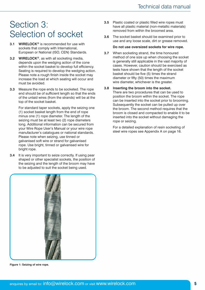
For standard taper sockets, apply the seizing one(1) socket basket length from the end of ropeminus one (1) rope diameter. The length of theseizing must be at least two (2) rope diameterslong. Additional information can be secured fromyour Wire Rope User’s Manual or your wire ropemanufacturer’s catalogues or national standards.Please note when seizing, use tinned orgalvanised soft wire or strand for galvanised rope. Use bright, tinned or galvanised wire for bright rope.
3.4 It is very important to seize correctly. If using pearshaped or other specialist sockets, the position ofthe seizing and the length of the broom may haveto be adjusted to suit the socket being used.
Figure 1: Seizing of wire rope.
3.5 Plastic coated or plastic filled wire ropes musthave all plastic material (non-metallic materials)removed from within the broomed area.
3.6 The socket basket should be examined prior touse and any loose scale, dirt or grease removed.
Do not use oversized sockets for wire rope.
3.7 When socketing strand, the time honouredmethod of one size up when choosing the socketis generally still applicable in the vast majority ofcases. However, caution should be exercised astests have shown that the length of the socketbasket should be five (5) times the stranddiameter or fifty (50) times the maximum wire diameter, whichever is the greater.
3.8 Inserting the broom into the socket. There are two procedures that can be used toposition the broom within the socket. The ropecan be inserted into the socket prior to brooming.Subsequently the socket can be pulled up overthe broom. The second method requires that thebroom is closed and compacted to enable it to beinserted into the socket without damaging therope or seizing.
For a detailed explanation of resin socketing ofsteel wire ropes see Appendix A on page 16.
enquires by email to: [email protected] or visit www.wirelock.com
6 For more information please contact us: call +44 (0) 191 264 8541
WIRELOCK®
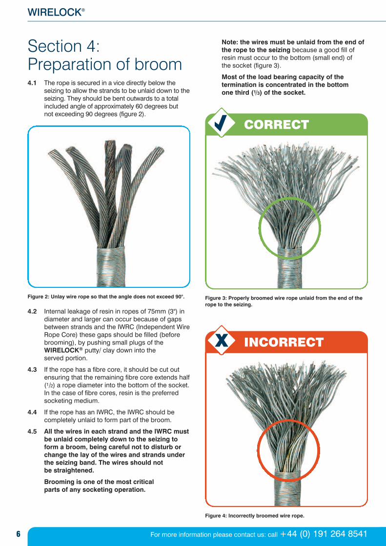
Section 4: Preparation of broom4.1 The rope is secured in a vice directly below the
seizing to allow the strands to be unlaid down to theseizing. They should be bent outwards to a totalincluded angle of approximately 60 degrees but not exceeding 90 degrees (figure 2).
Figure 2: Unlay wire rope so that the angle does not exceed 90°.
4.2 Internal leakage of resin in ropes of 75mm (3") indiameter and larger can occur because of gapsbetween strands and the IWRC (Independent WireRope Core) these gaps should be filled (beforebrooming), by pushing small plugs of theWIRELOCK® putty/ clay down into the served portion.
4.3 If the rope has a fibre core, it should be cut outensuring that the remaining fibre core extends half(1/2) a rope diameter into the bottom of the socket.In the case of fibre cores, resin is the preferredsocketing medium.
4.4 If the rope has an IWRC, the IWRC should becompletely unlaid to form part of the broom.
4.5 All the wires in each strand and the IWRC mustbe unlaid completely down to the seizing toform a broom, being careful not to disturb orchange the lay of the wires and strands underthe seizing band. The wires should not be straightened.
Brooming is one of the most critical parts of any socketing operation.
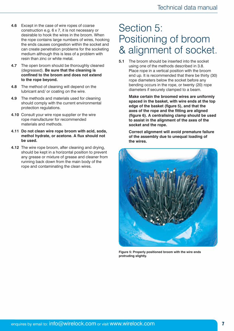
Note: the wires must be unlaid from the end ofthe rope to the seizing because a good fill ofresin must occur to the bottom (small end) of the socket (figure 3).
Most of the load bearing capacity of thetermination is concentrated in the bottom one third (1/3) of the socket.
Figure 3: Properly broomed wire rope unlaid from the end of therope to the seizing.
Figure 4: Incorrectly broomed wire rope.
CORRECT
INCORRECT
7
Technical data manual
enquires by email to: [email protected] or visit www.wirelock.com
4.6 Except in the case of wire ropes of coarseconstruction e.g. 6 x 7, it is not necessary ordesirable to hook the wires in the broom. Whenthe rope contains large numbers of wires, hookingthe ends causes congestion within the socket andcan create penetration problems for the socketingmedium although this is less of a problem withresin than zinc or white metal.
4.7 The open broom should be thoroughly cleaned(degreased). Be sure that the cleaning isconfined to the broom and does not extend to the rope beyond.
4.8 The method of cleaning will depend on thelubricant and/ or coating on the wire.
4.9 The methods and materials used for cleaningshould comply with the current environmentalprotection regulations.
4.10 Consult your wire rope supplier or the wire rope manufacturer for recommended materials and methods.
4.11 Do not clean wire rope broom with acid, soda,methol hydrate, or acetone. A flux should notbe used.
4.12 The wire rope broom, after cleaning and drying,should be kept in a horizontal position to preventany grease or mixture of grease and cleaner fromrunning back down from the main body of therope and contaminating the clean wires.
Section 5:Positioning of broom& alignment of socket.5.1 The broom should be inserted into the socket
using one of the methods described in 3.8. Place rope in a vertical position with the broomend up. It is recommended that there be thirty (30)rope diameters below the socket before anybending occurs in the rope, or twenty (20) ropediameters if securely clamped to a beam.
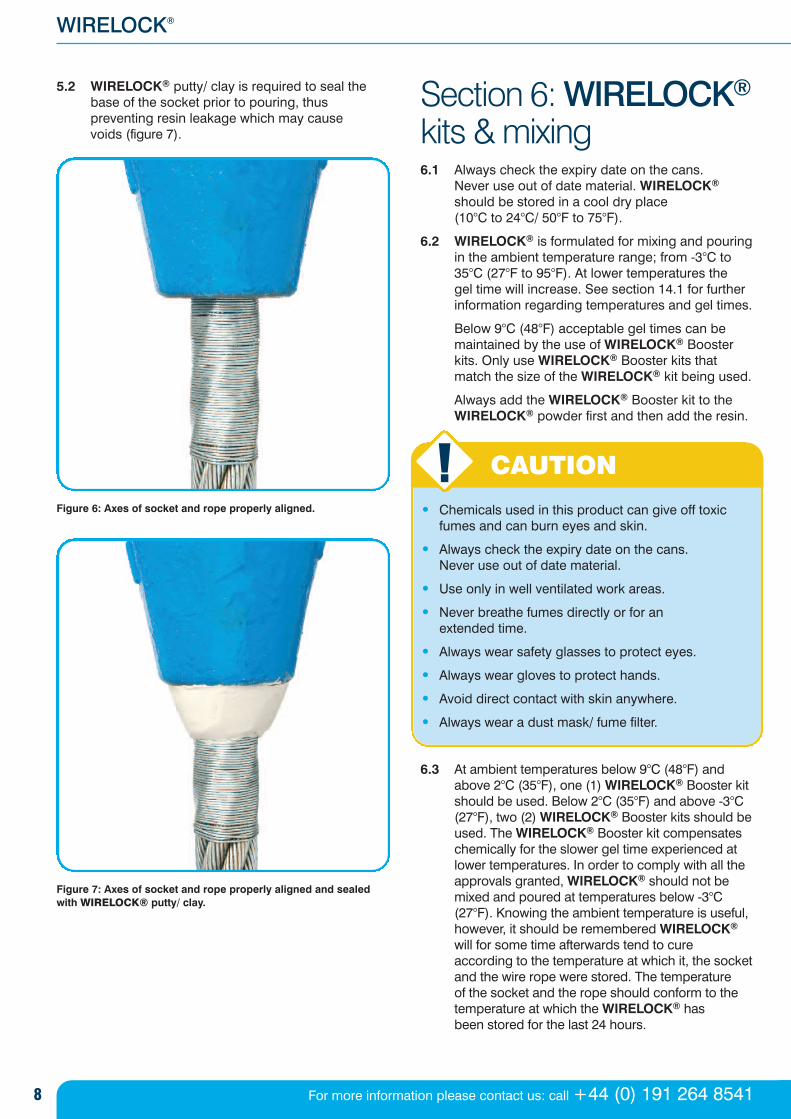
Make certain the broomed wires are uniformlyspaced in the basket, with wire ends at the topedge of the basket (figure 5), and that the axes of the rope and the fitting are aligned(figure 6). A centralising clamp should be usedto assist in the alignment of the axes of thesocket and the rope.
Correct alignment will avoid premature failureof the assembly due to unequal loading of the wires.
Figure 5: Properly positioned broom with the wire ends protruding slightly.
CAUTION
8 For more information please contact us: call +44 (0) 191 264 8541
WIRELOCK®
5.2 WIRELOCK® putty/ clay is required to seal thebase of the socket prior to pouring, thuspreventing resin leakage which may cause voids (figure 7).
Figure 6: Axes of socket and rope properly aligned.
Figure 7: Axes of socket and rope properly aligned and sealed with WIRELOCK® putty/ clay.
Section 6: WIRELOCK®
kits & mixing6.1 Always check the expiry date on the cans.
Never use out of date material. WIRELOCK®
should be stored in a cool dry place (10°C to 24°C/ 50°F to 75°F).
6.2 WIRELOCK® is formulated for mixing and pouringin the ambient temperature range; from -3°C to35°C (27°F to 95°F). At lower temperatures the gel time will increase. See section 14.1 for furtherinformation regarding temperatures and gel times.
Below 9°C (48°F) acceptable gel times can bemaintained by the use of WIRELOCK® Boosterkits. Only use WIRELOCK® Booster kits thatmatch the size of the WIRELOCK® kit being used.
Always add the WIRELOCK® Booster kit to theWIRELOCK® powder first and then add the resin.
• Chemicals used in this product can give off toxicfumes and can burn eyes and skin.
• Always check the expiry date on the cans. Never use out of date material.
• Use only in well ventilated work areas.
• Never breathe fumes directly or for an extended time.
• Always wear safety glasses to protect eyes.
• Always wear gloves to protect hands.
• Avoid direct contact with skin anywhere.
• Always wear a dust mask/ fume filter.
6.3 At ambient temperatures below 9°C (48°F) andabove 2°C (35°F), one (1) WIRELOCK® Booster kitshould be used. Below 2°C (35°F) and above -3°C(27°F), two (2) WIRELOCK® Booster kits should beused. The WIRELOCK® Booster kit compensateschemically for the slower gel time experienced atlower temperatures. In order to comply with all theapprovals granted, WIRELOCK® should not bemixed and poured at temperatures below -3°C(27°F). Knowing the ambient temperature is useful,however, it should be remembered WIRELOCK®
will for some time afterwards tend to cureaccording to the temperature at which it, the socketand the wire rope were stored. The temperature of the socket and the rope should conform to thetemperature at which the WIRELOCK® has been stored for the last 24 hours.
9
Technical data manual
enquires by email to: [email protected] or visit www.wirelock.com
If the socket, rope and WIRELOCK® are stored atnormal room temperature 18°C to 21°C (65°F to70°F) WIRELOCK® Booster kits must not be usedif the ambient temperature is below 9°C (48°F). If the ambient temperature is 35°C (95°F) orabove, the WIRELOCK® kit should be refrigerated for two hours before use.
6.4 It is possible to combine various kit sizes toachieve any required volume, e.g. 2500cc = 2 x1000cc plus 1 x 500cc, etc. In this case, pour all of the liquid resin into all of the powder beforemixing. Always mix all of the resin with all of thepowder. Never mix less than the total contentsof all cans.
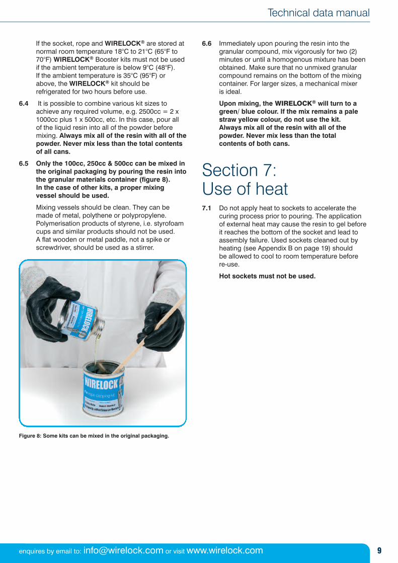
6.5 Only the 100cc, 250cc & 500cc can be mixed inthe original packaging by pouring the resin intothe granular materials container (figure 8). In the case of other kits, a proper mixing vessel should be used.
Mixing vessels should be clean. They can bemade of metal, polythene or polypropylene.Polymerisation products of styrene, i.e. styrofoamcups and similar products should not be used. A flat wooden or metal paddle, not a spike orscrewdriver, should be used as a stirrer.
Figure 8: Some kits can be mixed in the original packaging.
6.6 Immediately upon pouring the resin into thegranular compound, mix vigorously for two (2)minutes or until a homogenous mixture has beenobtained. Make sure that no unmixed granularcompound remains on the bottom of the mixingcontainer. For larger sizes, a mechanical mixer is ideal.
Upon mixing, the WIRELOCK® will turn to agreen/ blue colour. If the mix remains a palestraw yellow colour, do not use the kit. Always mix all of the resin with all of thepowder. Never mix less than the total contents of both cans.
Section 7: Use of heat7.1 Do not apply heat to sockets to accelerate the
curing process prior to pouring. The application of external heat may cause the resin to gel beforeit reaches the bottom of the socket and lead toassembly failure. Used sockets cleaned out byheating (see Appendix B on page 19) should be allowed to cool to room temperature before re-use.
Hot sockets must not be used.
10 For more information please contact us: call +44 (0) 191 264 8541
WIRELOCK®
Section 8: PouringWIRELOCK®
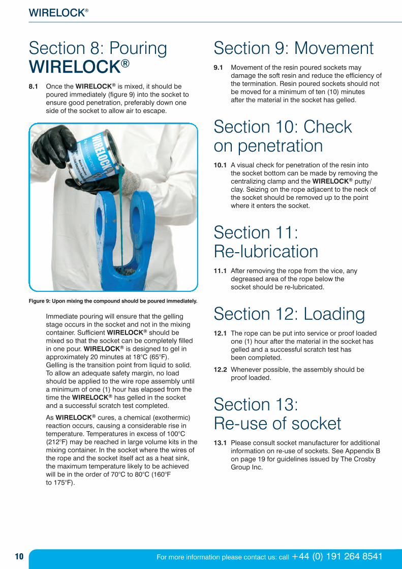
8.1 Once the WIRELOCK® is mixed, it should bepoured immediately (figure 9) into the socket toensure good penetration, preferably down oneside of the socket to allow air to escape.
Figure 9: Upon mixing the compound should be poured immediately.
Immediate pouring will ensure that the gellingstage occurs in the socket and not in the mixingcontainer. Sufficient WIRELOCK® should bemixed so that the socket can be completely filledin one pour. WIRELOCK® is designed to gel inapproximately 20 minutes at 18°C (65°F). Gelling is the transition point from liquid to solid.To allow an adequate safety margin, no loadshould be applied to the wire rope assembly untila minimum of one (1) hour has elapsed from thetime the WIRELOCK® has gelled in the socketand a successful scratch test completed.
As WIRELOCK® cures, a chemical (exothermic)reaction occurs, causing a considerable rise intemperature. Temperatures in excess of 100°C(212°F) may be reached in large volume kits in themixing container. In the socket where the wires ofthe rope and the socket itself act as a heat sink,the maximum temperature likely to be achievedwill be in the order of 70°C to 80°C (160°F to 175°F).
Section 9: Movement 9.1 Movement of the resin poured sockets may
damage the soft resin and reduce the efficiency ofthe termination. Resin poured sockets should notbe moved for a minimum of ten (10) minutes after the material in the socket has gelled.
Section 10: Check on penetration 10.1 A visual check for penetration of the resin into
the socket bottom can be made by removing thecentralizing clamp and the WIRELOCK® putty/clay. Seizing on the rope adjacent to the neck ofthe socket should be removed up to the pointwhere it enters the socket.
Section 11: Re-lubrication 11.1 After removing the rope from the vice, any
degreased area of the rope below the socket should be re-lubricated.
Section 12: Loading 12.1 The rope can be put into service or proof loaded
one (1) hour after the material in the socket hasgelled and a successful scratch test has been completed.
12.2 Whenever possible, the assembly should be proof loaded.
Section 13: Re-use of socket 13.1 Please consult socket manufacturer for additional
information on re-use of sockets. See Appendix Bon page 19 for guidelines issued by The CrosbyGroup Inc.
11
Technical data manual
enquires by email to: [email protected] or visit www.wirelock.com
Section 14: General information
1 WIRELOCK® is designed to gel (change from aliquid to a solid) in approximately 20 minutes at18°C (65°F). To ensure the kits are not adverselyaffected by storage, they should be kept in a dryplace at a temperature of between 10°C and 24°C(50°F and 75°F) and away from any source ofdirect heat. WIRELOCK®, like all polyester resins,is temperature sensitive. An increase intemperature of 10°C (18°F) will halve the gel time. A further increase of 10°C (18°F) will halve the geltime again. A decrease in temperature of 10°C(18°F) lengthens the gel time by approximately100%. A further decrease in temperature of 10°C(18°F) will lengthen the gel time by approximately100% again.
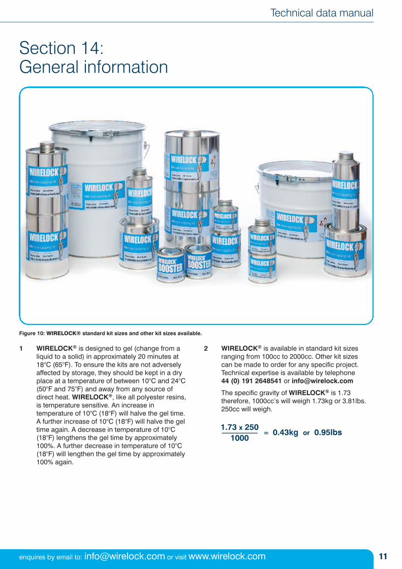
2 WIRELOCK® is available in standard kit sizesranging from 100cc to 2000cc. Other kit sizes can be made to order for any specific project.Technical expertise is available by telephone 44 (0) 191 2648541 or [email protected]
The specific gravity of WIRELOCK® is 1.73therefore, 1000cc’s will weigh 1.73kg or 3.81lbs.250cc will weigh.
Figure 10: WIRELOCK® standard kit sizes and other kit sizes available.
1.73 x 250––––
1000= 0.43kg or 0.95lbs
12 For more information please contact us: call +44 (0) 191 264 8541
WIRELOCK®
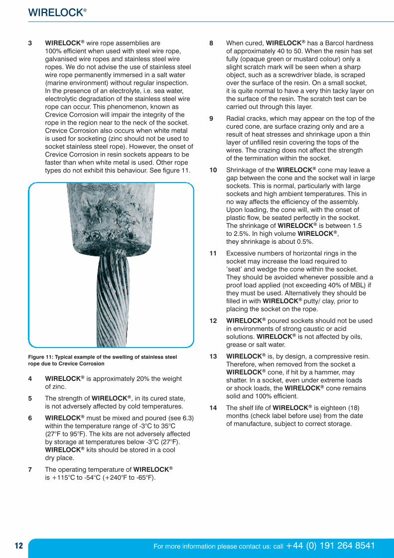
3 WIRELOCK® wire rope assemblies are 100% efficient when used with steel wire rope,galvanised wire ropes and stainless steel wireropes. We do not advise the use of stainless steelwire rope permanently immersed in a salt water(marine environment) without regular inspection.In the presence of an electrolyte, i.e. sea water,electrolytic degradation of the stainless steel wirerope can occur. This phenomenon, known asCrevice Corrosion will impair the integrity of therope in the region near to the neck of the socket.Crevice Corrosion also occurs when white metal is used for socketing (zinc should not be used tosocket stainless steel rope). However, the onset ofCrevice Corrosion in resin sockets appears to befaster than when white metal is used. Other ropetypes do not exhibit this behaviour. See figure 11.
Figure 11: Typical example of the swelling of stainless steel rope due to Crevice Corrosion
4 WIRELOCK® is approximately 20% the weight of zinc.
5 The strength of WIRELOCK®, in its cured state, is not adversely affected by cold temperatures.
6 WIRELOCK® must be mixed and poured (see 6.3)within the temperature range of -3°C to 35°C (27°F to 95°F). The kits are not adversely affectedby storage at temperatures below -3°C (27°F).WIRELOCK® kits should be stored in a cool dry place.
7 The operating temperature of WIRELOCK®
is +115°C to -54°C (+240°F to -65°F).
8 When cured, WIRELOCK® has a Barcol hardnessof approximately 40 to 50. When the resin has setfully (opaque green or mustard colour) only aslight scratch mark will be seen when a sharpobject, such as a screwdriver blade, is scrapedover the surface of the resin. On a small socket, it is quite normal to have a very thin tacky layer onthe surface of the resin. The scratch test can becarried out through this layer.
9 Radial cracks, which may appear on the top of thecured cone, are surface crazing only and are aresult of heat stresses and shrinkage upon a thinlayer of unfilled resin covering the tops of thewires. The crazing does not affect the strength of the termination within the socket.
10 Shrinkage of the WIRELOCK® cone may leave agap between the cone and the socket wall in largesockets. This is normal, particularly with largesockets and high ambient temperatures. This inno way affects the efficiency of the assembly.Upon loading, the cone will, with the onset ofplastic flow, be seated perfectly in the socket. The shrinkage of WIRELOCK® is between 1.5 to 2.5%. In high volume WIRELOCK®, they shrinkage is about 0.5%.
11 Excessive numbers of horizontal rings in thesocket may increase the load required to ‘seat’ and wedge the cone within the socket. They should be avoided whenever possible and aproof load applied (not exceeding 40% of MBL) ifthey must be used. Alternatively they should befilled in with WIRELOCK® putty/ clay, prior toplacing the socket on the rope.
12 WIRELOCK® poured sockets should not be usedin environments of strong caustic or acidsolutions. WIRELOCK® is not affected by oils,grease or salt water.
13 WIRELOCK® is, by design, a compressive resin.Therefore, when removed from the socket aWIRELOCK® cone, if hit by a hammer, mayshatter. In a socket, even under extreme loads or shock loads, the WIRELOCK® cone remains solid and 100% efficient.
14 The shelf life of WIRELOCK® is eighteen (18)months (check label before use) from the date of manufacture, subject to correct storage.

13
Technical data manual
enquires by email to: [email protected] or visit www.wirelock.com
Section 15: Approvals & NATO numbersApprovals To maintain WIRELOCK’s premier position in themarketplace we continually strive to refine and improvethe product. We operate a monitoring programme toensure that the quality of WIRELOCK® never varies.
WIRELOCK® is manufactured under ISO 9001accreditation.
WIRELOCK® meets the requirements of ISO 17558 and DNV-OS-E304.
WIRELOCK® has Type Approval from Lloyds, DNV and ABS.
NATO numbers 100cc ................................................................8030-21-902-1823
250cc ................................................................8030-21-902-1824
500cc ................................................................8030-21-902-1825
1000cc..............................................................8030-21-902-1826
14 For more information please contact us: call +44 (0) 191 264 8541
WIRELOCK®
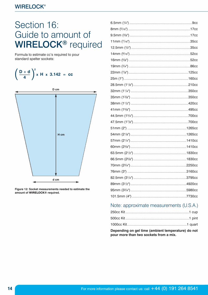
Section 16: Guide to amount ofWIRELOCK® requiredFormula to estimate cc’s required to pour standard spelter sockets:
Figure 12: Socket measurements needed to estimate the amount of WIRELOCK® required.
6.5mm (1/4") ..................................................................................9cc
8mm (5/16") .................................................................................17cc
9.5mm (3/8") ...............................................................................17cc
11mm (7/16")...............................................................................35cc
12.5mm (1/2") .............................................................................35cc
14mm (9/16")...............................................................................52cc
16mm (5/8") ................................................................................52cc
19mm (3/4") ................................................................................86cc
22mm (7/8")..............................................................................125cc
25m (1")....................................................................................160cc
28.5mm (11/8")........................................................................210cc
32mm (11/4") ...........................................................................350cc
35mm (13/8") ...........................................................................350cc
38mm (11/2") ...........................................................................420cc
41mm (15/8") ...........................................................................495cc
44.5mm (13/4")........................................................................700cc
47.5mm (17/8")........................................................................700cc
51mm (2") .............................................................................1265cc
54mm (21/8").........................................................................1265cc
57mm (21/4").........................................................................1410cc
60mm (23/8").........................................................................1410cc
63.5mm (21/2") .....................................................................1830cc
66.5mm (25/8") .....................................................................1830cc
70mm (23/4").........................................................................2250cc
76mm (3") .............................................................................3160cc
82.5mm (31/4") .....................................................................3795cc
89mm (31/2").........................................................................4920cc
95mm (33/4").........................................................................5980cc
101.5mm (4") .......................................................................7730cc
Note: approximate measurements (U.S.A.)250cc Kit ...................................................................................1 cup
500cc Kit ...................................................................................1 pint
1000cc Kit..............................................................................1 quart
Depending on gel time (ambient temperature) do notpour more than two sockets from a mix.
d cm
H cm
D cm
D + d––
4x H x 3.142 = cc
2( )
15
Technical data manual
enquires by email to: [email protected] or visit www.wirelock.com
Section 17: Properties of WIRELOCK®
WIRELOCK® in its liquid state is flammable. Flash point31°C (88°F). Please note: flash point is not the autoignition (spontaneous combustion) temperature, but thetemperature above which the material will give off asignificant amount of vapour.
Performance criteria
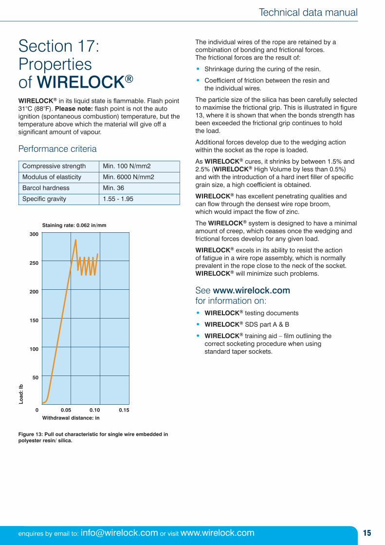
Figure 13: Pull out characteristic for single wire embedded inpolyester resin/ silica.
The individual wires of the rope are retained by acombination of bonding and frictional forces. The frictional forces are the result of:
• Shrinkage during the curing of the resin.
• Coefficient of friction between the resin and the individual wires.
The particle size of the silica has been carefully selectedto maximise the frictional grip. This is illustrated in figure13, where it is shown that when the bonds strength hasbeen exceeded the frictional grip continues to hold the load.
Additional forces develop due to the wedging actionwithin the socket as the rope is loaded.
As WIRELOCK® cures, it shrinks by between 1.5% and2.5% (WIRELOCK® High Volume by less than 0.5%)and with the introduction of a hard inert filler of specificgrain size, a high coefficient is obtained.
WIRELOCK® has excellent penetrating qualities andcan flow through the densest wire rope broom, which would impact the flow of zinc.
The WIRELOCK® system is designed to have a minimalamount of creep, which ceases once the wedging andfrictional forces develop for any given load.
WIRELOCK® excels in its ability to resist the action of fatigue in a wire rope assembly, which is normallyprevalent in the rope close to the neck of the socket.WIRELOCK® will minimize such problems.
See www.wirelock.comfor information on:• WIRELOCK® testing documents
• WIRELOCK® SDS part A & B
• WIRELOCK® training aid – film outlining the correct socketing procedure when using standard taper sockets.
Compressive strength Min. 100 N/mm2
Modulus of elasticity Min. 6000 N/mm2
Barcol hardness Min. 36
Specific gravity 1.55 - 1.95
300
250
200
150
100
50
0.150.100.050
Withdrawal distance: in
Load
: lb
Staining rate: 0.062 in/mm
16 For more information please contact us: call +44 (0) 191 264 8541
WIRELOCK®
Appendix A: Resin socketing of steel wire ropeBy J.M. Dodd B.Sc
Millfield Enterprises, 16 Shelley Road, Newburn Industrial Estate, Newburn,Newcastle Upon Tyne NE15 9RT, England
The concept is not new. The first published data on this topic were produced in the early sixties. In essence,these two papers by Doherty and Campbell, stated thatthe resin filled sockets under either static tension(tensile) or fluctuating tension (fatigue) could offerstrengths that were comparable with those of the rope itself.
There is a dearth of information on socketing and themechanisms by which it works, so it was necessary toestablish some basic knowledge before a resinsocketing system could be designed.
In theory, the requirements for a successful system are:
1. High bond strength between resin and wire
2. High modulus of elasticity
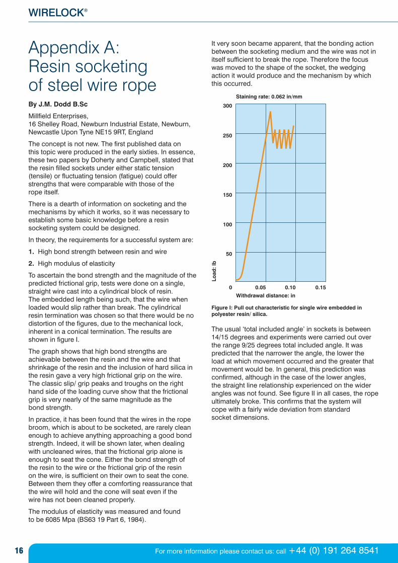
To ascertain the bond strength and the magnitude of thepredicted frictional grip, tests were done on a single,straight wire cast into a cylindrical block of resin. The embedded length being such, that the wire whenloaded would slip rather than break. The cylindricalresin termination was chosen so that there would be nodistortion of the figures, due to the mechanical lock,inherent in a conical termination. The results are shown in figure I.
The graph shows that high bond strengths areachievable between the resin and the wire and thatshrinkage of the resin and the inclusion of hard silica inthe resin gave a very high frictional grip on the wire. The classic slip/ grip peaks and troughs on the righthand side of the loading curve show that the frictionalgrip is very nearly of the same magnitude as the bond strength.
In practice, it has been found that the wires in the ropebroom, which is about to be socketed, are rarely cleanenough to achieve anything approaching a good bondstrength. Indeed, it will be shown later, when dealingwith uncleaned wires, that the frictional grip alone isenough to seat the cone. Either the bond strength of the resin to the wire or the frictional grip of the resin on the wire, is sufficient on their own to seat the cone. Between them they offer a comforting reassurance thatthe wire will hold and the cone will seat even if the wire has not been cleaned properly.
The modulus of elasticity was measured and found to be 6085 Mpa (BS63 19 Part 6, 1984).
It very soon became apparent, that the bonding actionbetween the socketing medium and the wire was not initself sufficient to break the rope. Therefore the focuswas moved to the shape of the socket, the wedgingaction it would produce and the mechanism by whichthis occurred.
Figure I: Pull out characteristic for single wire embedded inpolyester resin/ silica.
The usual ‘total included angle’ in sockets is between14/15 degrees and experiments were carried out overthe range 9/25 degrees total included angle. It waspredicted that the narrower the angle, the lower the load at which movement occurred and the greater thatmovement would be. In general, this prediction wasconfirmed, although in the case of the lower angles, the straight line relationship experienced on the widerangles was not found. See figure II in all cases, the ropeultimately broke. This confirms that the system will cope with a fairly wide deviation from standard socket dimensions.
300
250
200
150
100
50
0.150.100.050
Withdrawal distance: in
Load
: lb
Staining rate: 0.062 in/mm
17
Technical data manual
enquires by email to: [email protected] or visit www.wirelock.com
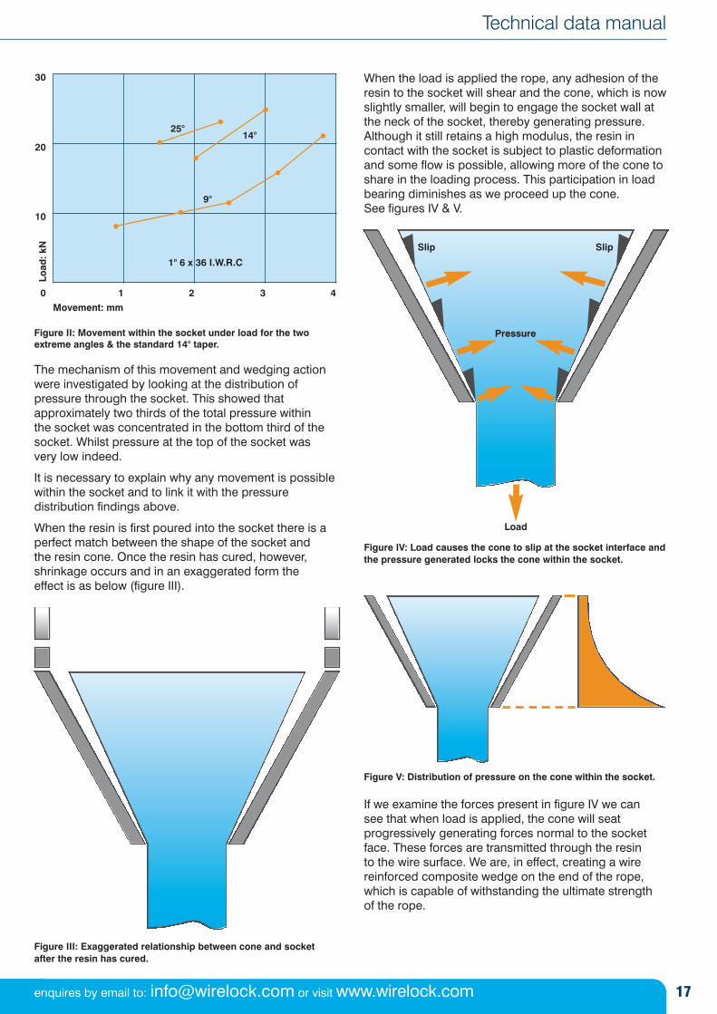
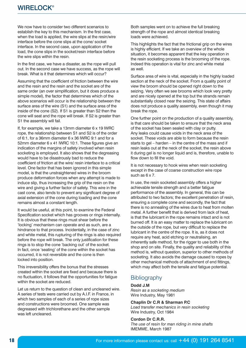
Figure II: Movement within the socket under load for the twoextreme angles & the standard 14° taper.
The mechanism of this movement and wedging actionwere investigated by looking at the distribution ofpressure through the socket. This showed thatapproximately two thirds of the total pressure within the socket was concentrated in the bottom third of thesocket. Whilst pressure at the top of the socket was very low indeed.
It is necessary to explain why any movement is possiblewithin the socket and to link it with the pressuredistribution findings above.
When the resin is first poured into the socket there is aperfect match between the shape of the socket and the resin cone. Once the resin has cured, however,shrinkage occurs and in an exaggerated form the effect is as below (figure III).
Figure III: Exaggerated relationship between cone and socketafter the resin has cured.
When the load is applied the rope, any adhesion of theresin to the socket will shear and the cone, which is nowslightly smaller, will begin to engage the socket wall atthe neck of the socket, thereby generating pressure.Although it still retains a high modulus, the resin incontact with the socket is subject to plastic deformationand some flow is possible, allowing more of the cone toshare in the loading process. This participation in loadbearing diminishes as we proceed up the cone. See figures IV & V.
Figure IV: Load causes the cone to slip at the socket interface andthe pressure generated locks the cone within the socket.
Figure V: Distribution of pressure on the cone within the socket.
If we examine the forces present in figure IV we can see that when load is applied, the cone will seatprogressively generating forces normal to the socketface. These forces are transmitted through the resin to the wire surface. We are, in effect, creating a wirereinforced composite wedge on the end of the rope,which is capable of withstanding the ultimate strength of the rope.
Movement: mm
30
25°14°
9°
20
Load
: kN
10
0 1 2 3 4
1" 6 x 36 I.W.R.C
Load
Pressure
Slip Slip
18 For more information please contact us: call +44 (0) 191 264 8541
WIRELOCK®
We now have to consider two different scenarios toestablish the key to this mechanism. In the first case,when the load is applied, the wire slips at the resin/wireinterface before the cone slips at the cone/ socketinterface. In the second case, upon application of theload, the cone slips in the socket/resin interface beforethe wire slips within the resin.
In the first case, we have a disaster, as the rope will pullout. In the second case we have success, as the rope willbreak. What is it that determines which will occur?
Assuming that the coefficient of friction between the wireand the resin and the resin and the socket are of thesame order (an over simplification, but it does produce asimple model), the factor that determines which of theabove scenarios will occur is the relationship between thesurface area of the wire (S1) and the surface area of theinside of the cone (S2). If S1 is greater than S2 then thecone will seat and the rope will break. If S2 is greater thanS1 the assembly will fail.
If, for example, we take a 13mm diameter 6 x 19 IWRCrope, the relationship between S1 and S2 is of the orderof 6:1, for a 36mm diameter 6 x 36 IWRC 9:1 and for a52mm diameter 6 x 41 IWRC 10:1. These figures give anindication of the margins of safety involved when resinsocketing is employed. It also shows that the degreasingwould have to be disastrously bad to reduce thecoefficient of friction at the wire/ resin interface to a criticallevel. One factor that has been ignored in this simplemodel, is that the unstraightened wires in the broomproduce deformation forces when any attempt is made toinduce slip, thus increasing the grip of the resin on thewire and giving a further factor of safety. This wire in thecast cone, also tends to prevent any significant degree ofaxial extension of the cone during loading and the coneremains almost a constant length.
It would be useful, at this point, to examine the FederalSpecification socket which has grooves or rings internally.It is obvious that these rings must shear before the‘locking’ mechanism can operate and as such, are ahindrance to that process. Incidentally, in the case of zincand white metal, this rupturing of the rings is also requiredbefore the rope will break. The only justification for theserings is to stop the cone ‘backing out’ of the socket. In fact, once ‘seating’ of the cone within the socket hasoccurred, it is not reversible and the cone is then locked into position.
This irreversibility offers the bonus that the stressescreated within the socket are fixed and because there isno fluctuation, it follows that the opportunities for fatiguewithin the socket are reduced.
Let us return to the question of clean and uncleaned wire.A series of tests were carried out by A.I.F. in France, inwhich two samples of each of a series of rope sizes and constructions were broomed. One sample wasdegreased with trichlorethane and the other sample was left uncleaned.
Both samples went on to achieve the full breakingstrength of the rope and almost identical breaking loads were achieved.
This highlights the fact that the frictional grip on the wiresis highly efficient. If we take an overview of the wholesituation, it becomes apparent that the key operation inthe resin socketing process is the brooming of the rope.Indeed this operation is vital for zinc and white metal as well.
Surface area of wire is vital, especially in the highly loadedsection at the neck of the socket. From a quality point ofview the broom should be opened right down to theseizing. Very often we see brooms which look very prettyand are nicely opened at the top but the strands remainsubstantially closed near the seizing. This state of affairsdoes not produce a quality assembly, even though it maybreak the rope.
One further point on the production of a quality assembly,is that care should be taken to ensure that the neck areaof the socket has been sealed with clay or putty. Any leaks could cause voids in the neck area of thesocket. These voids are able to form because the resinstarts to gel – harden – in the centre of the mass and ifresin leaks out at the neck of the socket, the resin above it during gel is no longer liquid and is, therefore, unable toflow down to fill the void.
It is not necessary to hook wires when resin socketingexcept in the case of coarse construction wire rope such as 6 x 7.
In use, the resin socketed assembly offers a higherachievable tensile strength and a better fatigueperformance of the assembly. In general, this can beattributed to two factors; the excellent penetration of resin,ensuring a complete cone and secondly, the fact thatthere is no annealing of the wires due to heat from moltenmetal. A further benefit that is derived from lack of heat, is that the lubricant in the rope remains intact and is notburned off. It is an easy matter to replace the lubricant onthe outside of the rope, but very difficult to replace thelubricant in the centre of the rope. It is, as it does notrequire any heat, acid etching or neutralising, aninherently safe method, for the rigger to use both in theshop and on site. Finally, the quality and reliability of thismethod is, without question, superior to other methods ofsocketing. It also avoids the damage caused to ropes byother mechanical methods of attachment of end fittings,which may affect both the tensile and fatigue potential.
Bibliography Dodd J.MResin as a socketing mediumWire Industry, May 1981
Chaplin Dr C.R & Sharman P.CLoad transfer mechanics in resin socketingWire Industry, Oct 1984
Cordon Dr C.R.R.The use of resin for man riding in mine shaftsIMEMME, March 1987
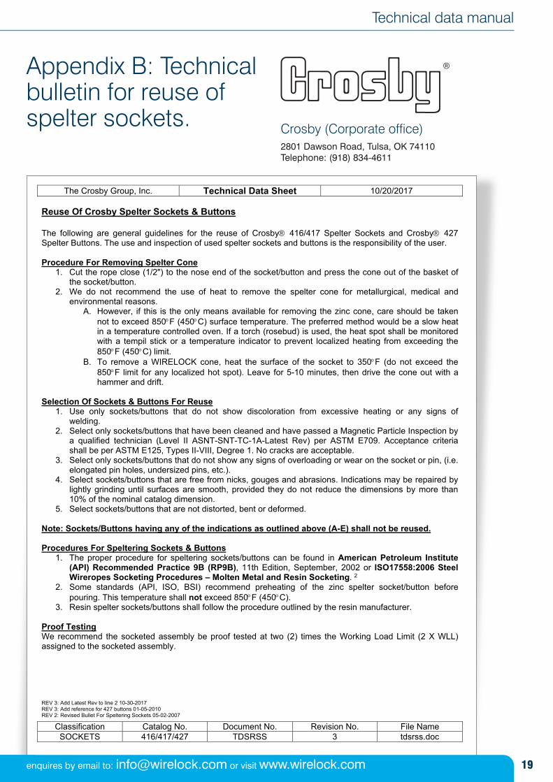
Appendix B: Technicalbulletin for reuse ofspelter sockets. Crosby (Corporate office)
2801 Dawson Road, Tulsa, OK 74110Telephone: (918) 834-4611
The Crosby Group, Inc. Technical Data Sheet 10/20/2017
Classification Catalog No. Document No. Revision No. File Name SOCKETS 416/417/427 TDSRSS 3 tdsrss.doc
Reuse Of Crosby Spelter Sockets & Buttons The following are general guidelines for the reuse of Crosby 416/417 Spelter Sockets and Crosby 427 Spelter Buttons. The use and inspection of used spelter sockets and buttons is the responsibility of the user. Procedure For Removing Spelter Cone
1. Cut the rope close (1/2") to the nose end of the socket/button and press the cone out of the basket of the socket/button.
2. We do not recommend the use of heat to remove the spelter cone for metallurgical, medical and environmental reasons.
A. However, if this is the only means available for removing the zinc cone, care should be taken not to exceed 850F (450C) surface temperature. The preferred method would be a slow heat in a temperature controlled oven. If a torch (rosebud) is used, the heat spot shall be monitored with a tempil stick or a temperature indicator to prevent localized heating from exceeding the 850F (450C) limit.
B. To remove a WIRELOCK cone, heat the surface of the socket to 350F (do not exceed the 850F limit for any localized hot spot). Leave for 5-10 minutes, then drive the cone out with a hammer and drift.
Selection Of Sockets & Buttons For Reuse
1. Use only sockets/buttons that do not show discoloration from excessive heating or any signs of welding.
2. Select only sockets/buttons that have been cleaned and have passed a Magnetic Particle Inspection by a qualified technician (Level II ASNT-SNT-TC-1A-Latest Rev) per ASTM E709. Acceptance criteria shall be per ASTM E125, Types II-VIII, Degree 1. No cracks are acceptable.
3. Select only sockets/buttons that do not show any signs of overloading or wear on the socket or pin, (i.e. elongated pin holes, undersized pins, etc.).
4. Select sockets/buttons that are free from nicks, gouges and abrasions. Indications may be repaired by lightly grinding until surfaces are smooth, provided they do not reduce the dimensions by more than 10% of the nominal catalog dimension.
5. Select sockets/buttons that are not distorted, bent or deformed. Note: Sockets/Buttons having any of the indications as outlined above (A-E) shall not be reused. Procedures For Speltering Sockets & Buttons
1. The proper procedure for speltering sockets/buttons can be found in American Petroleum Institute (API) Recommended Practice 9B (RP9B), 11th Edition, September, 2002 or ISO17558:2006 Steel Wireropes Socketing Procedures – Molten Metal and Resin Socketing. 2
2. Some standards (API, ISO, BSI) recommend preheating of the zinc spelter socket/button before pouring. This temperature shall not exceed 850F (450C).
3. Resin spelter sockets/buttons shall follow the procedure outlined by the resin manufacturer. Proof Testing We recommend the socketed assembly be proof tested at two (2) times the Working Load Limit (2 X WLL) assigned to the socketed assembly. REV 3: Add Latest Rev to line 2 10-30-2017 REV 3: Add reference for 427 buttons 01-05-2010 REV 2: Revised Bullet For Speltering Sockets 05-02-2007
19
Technical data manual
enquires by email to: [email protected] or visit www.wirelock.com

For more information about WIRELOCK® please contact us:
T +44 (0) 191 264 8541 E [email protected]
www.wirelock.comManual version: 2–11/17
WIRELOCK® is part of the groupMillfield Enterprises (Manufacturing) Ltd 16 Shelley Road Newburn Industrial Estate Newcastle upon Tyne NE15 9RT www.millfield-group.co.uk