Embed Size (px)
Citation preview

®
The power in relays and timers since 1954S.p.A
ISO 9001 STANDARD
TTIIMMEERRSSTechnical Data - 2000.4 English
RATED VOLTAGE - it is the nominal value of the operating voltage of the circuit by which the relay is designed to be supplied and operate. Therelays operating and use characteristics are referred to the rated voltage (EN 61810-1).
OPERATING RANGE - it is the range between the minimum and the maximum pick-up voltage.
DIELECTRIC STRENGTH - dielctric strength tests are carried out by applying a specified AC voltage (at 50 hz) for 1 minute between twocircuits (ex. between coil and contacts, between adjacent contacts, between open contacts), and verifying that the leakage current does notoverrun 10 mA. During the final 100% tests, the specified voltage is increased by 10%, and applied for 1 second. This refers to the rms value.
INSULATION GROUP - according to VDE 0110.
MECHANICAL LIFE - this test is carried out by energizing the coil without any load applied to the contacts, in order to check metalparts life, solder and residual magnetism intensity, which is checked by connecting one phase of each relay coil in parallel, while theother phase in connected to a contact of a pilot relay. This makes each relay independent in order to avoid induced counterelectromotive force which could facilitate the drop-out of the relay withsome residual magnetism (EN 61810-1) still on.
AMBIENT TEMPERATURE - it is the temperature of the actual area where the relay is located in which a good operation of the relay isguaranteed. The relay is energized at the rated voltage (or at the voltage indicated in the diagrams, which shows the trend of operatingminimum voltage versus temperature). All technical data in this catalogue refer to an ambient temperature +20°C.
TIME SETTING - range in which it is possible to set timing using the time scales.
REPEATABILITY - difference between the upper and lower limits of the confidence range from several time measurements of a specified time relayunder identical stated conditions. Preferably the repeatability is indicated as a percentage of the mean value of all measured values.
SETTING ACCURACY - difference between the measured value of the specified time and the reference value set on the scale.
RECOVERY TIME - necessary time to start the relay again with the defined accuracy after the input energizing quantity has been taken away.
CONTACT SPECIFICATION
RATED POWER - it is the maximum switching power or maximum power value (in VA) with resistive load in AC, that a contact can make, holdand break many times.
RATED CURRENT - this is the current for continuous duty, which is the highest value (rms value in AC) that a contact can continuously holdwithin the prescribed temperature limits. It coincides with the cycling capacity, that is the current that a contact can make, hold and break manytimes (EN 60225-23).
MAXIMUM PEAK CURRENT - the highest value of current (rms value in AC) that a contact can make and cycle for not more than 0.5 seconds, andwith a duty cycle (DC) not higher than 0.1, without undergoing a permanent degradation of its characteristics due to generated heat (EN 60225-23).
RATED VOLTAGE - it is the ratio between the rated power and the rated current.
MAXIMUM SWITCHING VOLTAGE - it is the highest voltage level that the contacts can switch. It is higher than or equal to the rated voltage.
BREAKING CAPACITY IN DC1 - for DC1 loads, it is the maximum value of current which contacts can switch, depending on the value of theload voltage, without any protection circuits.
SINGLE PHASE MOTOR RATING - it is the nominal value of the motors power, using AC3 category, cos ϕ = 0.7, 250 V maximum that arelay can control according to EN 60947-1, UL 508 e CSA 22.2 No.14.
Terminology

EMC SPECIFICATIONS
General
RADIATED AND CONDUCTED EMISSION EN 55022
TYPE OF TEST REFERENCE STANDARDELECTROSTATIC DISCHARGE - contact discharge EN 61000-4-2
- air discharge
RADIO-FREQUENCY ELECTROMAGNETIC FIELD (80 ÷ 1000 MHz) ENV 50140 (IEC 1000-4-3)
FAST TRANSIENTS (burst) (5-50 ns, 5 kHz) on Supply terminals EN 61000-4-4
SURGES (1.2/50 µs) on Supply terminals
- common mode EN 61000-4-5
- differential mode
RADIO-FREQUENCY COMMON MODE (0.15 ÷ 80 MHz) ENV 50141 (IEC 1000-4-6)on Supply terminals
POWER-FREQUENCY (50 Hz) EN 61000-4-8

81 SERIESMulti-function Modular Timers 16 A
85 SERIESMiniature Plug-in Timers 5 - 10 A
94 SERIESSockets and Accessoriesfor 85 Series Timers
82 SERIESModular Timers 5 A
87 SERIESModular Timers 5 - 8 A
86 SERIESTimer Modules
Timers
1
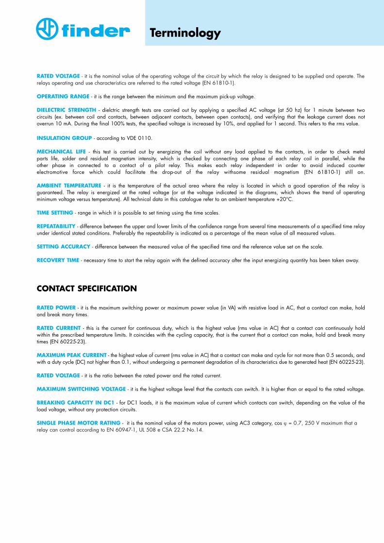
81 SeriesMulti-function Modular Timers 16 A
A range of mono or multi-voltage multi-function timersFeatures include:• One module (17.5 mm) wide housing• Seven functions (4 with supply start and 3 with external start)• Six time scales, from 0.1s to 10h• Supply voltage: 12...230 V AC/DC (non polarized) (type 81.01)
12, 24, 48, 110 V AC/DC (non polarized)230 V AC (type 81.11)
• External START activated by a make contact, not requiring an additional voltage supply• Instantaneous RESET facility• 35 mm rail (EN 50022) mount• Protection category IP 20• LEDs provided: GREEN = power ON
RED = relay ON• Conforms to EN 61812-1 standard

MULTI-FUNCTION MODULAR TIMERS 16 ATYPE 81.11 1 COSupply voltages available:12 V AC/DC (non polarized)24 V AC/DC (non polarized)48 V AC/DC (non polarized)110 V AC/DC (non polarized)230 V AC- Functions: see page 3- Ordering information: see page 5
81 SeriesMulti-function Modular Timers 16 A
2
81.01 81.11
MULTI-FUNCTION MODULAR TIMERS 16 ATYPE 81.01 1 COMulti-voltage from 12 V to 230 V in AC and in DC (non polarized).Automatically recognizes supply voltage used. The device can be supplied with any voltage from 12 to 230 V, both in AC and in DC(non polarized).- Functions: see page 3- Ordering information: see page 5
TYPE OF TEST REFERENCE STANDARD 81.01 81.11ELECTROSTATIC DISCHARGE - contact discharge EN 61000-4-2 4 kV 4 kV
- air discharge 8 kV 8 kV
RADIO-FREQUENCY ELECTROMAGNETIC FIELD (80 ÷ 1000 MHz) ENV 50140 (IEC 1000-4-3) 10 V/m 10 V/m
FAST TRANSIENTS (burst) (5-50 ns, 5 kHz) on Supply terminals EN 61000-4-4 4 kV 4 kV
SURGES (1.2/50 µs) on Supply terminals
- common mode EN 61000-4-5 4 kV 4 kV
- differential mode 2 kV 2 kV
RADIO-FREQUENCY COMMON MODE (0.15 ÷ 80 MHz) ENV 50141 (IEC 1000-4-6) 10 V 10 Von Supply terminals
RADIATED AND CONDUCTED EMISSION EN 55022 class A class B
EMC SPECIFICATIONS
84
17.4
45
59
43.5
26.5
84
17.4
45
59
43.5
26.5

81 SeriesMulti-function Modular Timers 16 A
3
The (C) indicated in the diagrams refers to the position of the NO contact. When the red LED (C) is illuminated the NO contact is closed.
DESCRIPTION OF THE FUNCTIONS
ContactsNO contactposition
Supplyvoltage
LEDgreen red
NO
YES
YES
U = Supply voltage
S = START
C = Relay contact (NO)
open
open
closed
15 - 18
15 - 18
15 - 16
15 - 16
15 - 16
15 - 18
open closed
(AI) ON delay.Apply power to timer. Contact transfers after preset time has elapsed. Reset occurs when power is removed.
(DI) ON pulse.Apply power to timer. Contact transfers immediately. After preset time has elapsed, contact returns to original position.
(SW) Symmetrical recycler: pulse start.Apply power to timer. First transfer of contact occurs as soon as power is applied. The timer now cycles between ON and OFF as long as power isapplied. The ratio is 1:1 (time off = time on).
(SP) Symmetrical recycler: pause start.Apply power to timer. First transfer of contact occurs after preset time haselapsed. The timer now cycles between OFF and ON as long as power isapplied. The ratio is 1:1 (time off = time on).
T
123
U
Ct<T
T
123
U
Ct<T
T T T T
123
U
Ct<T
T T T TT
123
U
Ct<T
(BE) OFF delay: timing on START release (internal start).Power must be applied at all times to timer.On closure of normally open control Signal Switch, the output contacttransfers and remains in that position. When the Signal Switch is reopened, the desired delay begins.After preset time has elapsed, the contact returns to the original position.
(DE) ON pulse: timing on START pulse.Power must be applied at all times to timer.On momentary or maintained closure of a normally open control SignalSwitch, the output contact transfers. After the desired time has elapsed, the contact returns to the original position.
(EE) OFF pulse: timing on START release.Power must be applied at all times to timer.On opening a normally open control Signal Switch, the output contacttransfers. After the desired time has elapsed, the contact returns to the original position.
TTT
U
S
123 C
T
U
S
C
123
TT T
TT
U
SC
123
T
On depressing the External Reset Switch the timer is immediately released.Releasing the Reset Switch reactivates the function.Example: ON delay function.
Depressing the External Reset Switch terminates the interval time.To re-start, it is necessary to depress the Start switch again.Example: ON pulse function.
T
123
U
R
C
T T
123
T T
U
S
R
Ct<T
In each and everyfunction and timescale, the timer isimmediately released when the reset switch is depressed.
External StartControlled throughsignal contact ofexternal start switch.
Internal StartControlled throughsignal contact involtage supply line.
**Reset
R X S 16
A1 A2 18 15
L/+ N/–
**Reset
R X S 16
A1 A2 18 15
L/+ N/–
*Start
RESET FUNCTION(R)

81 SeriesMulti-function Modular Timers 16 A
4
MAX AMBIENT TEMPERATUREVERSUS SUPPLY VOLTAGE (for timer type 81.01).If the apparatus operates at atemperature near the [R 81] limitcurve, adequate ventilation mustbe provided.Minimum ambient temperature:-10°C.
R 81
50
45
40
35
30
25
20
T[°C]
11 UB [V]220 230 240 250
81.01 81.11SUPPLY VOLTAGE (UN) (12 ... 230) V AC/DC (non polarized) 12, 24, 48, 110 V AC/DC (non polarized)
230 V ACOPERATING RANGE Umin = 11 V Umin = 0.85 UN
Umax = 250 V Umax = 1.1 UN
POWER CONSUMPTION relay OFF: < 35 mW at 12 V; < 1.7 W at 230 V < 50 mWrelay ON: < 400 mW at 12 V; < 2 W at 230 V < 700 mW
DIELECTRIC STRENGTH BETWEEN OPEN CONTACTS 1,000 V AC 1,000 V ACMECHANICAL LIFE 20 · 106 cycles 20 · 106 cycles PROTECTION CATEGORY IP 20 IP 20DELAY SETTING 0.1 s...10h (see time scales) 0.1 s...10h (see time scales)REPEATABILITY ± 1 % ± 1 %SETTING ACCURACY - FULL RANGE ± 5 % ± 5 %RECOVERY TIME ≤ 100 ms ≤ 100 msMINIMUM START/RESET PULSE DURATION 50 ms 50 msAMBIENT TEMPERATURE see diagram R 81 (–10...+50)°CPOWER LOST IN THE ENVIRONMENT 12 V AC/DC 230 V AC/DC 12 V AC/DC 230 V AC/DC- without load: 0.03 W 1.03 W 0.05 W 2.2 W- at full load: 1.9 W 3.2 W 0.9 W 3.4 W
WORKING CONDITIONSIn conformity with EC Directive on EMC (89/336), the timer has a high level of immunity, both from radiated and conducted disturbances (according to EN 61812-1). However, the timer (and its supply and control wiring) must be installed as far as possible from disturbance sources (such as transformers, contactors, circuit-breakers and their power cables). The cables for Start and Reset contact wiring must be short and, if possible, shielded.
TECHNICAL DATA
TIME SCALES
123456
(0,1…1) s123456
(1…10) s123456
(10…60) s123456
(1…10) min123456
(10…60) min123456
(1…10) h

Coil voltage012 = 12 V AC/DC024 = 24 V AC/DC048 = 48 V AC/DC110 = 110 V AC/DC230 = 230 V AC230 = 12 ... 230 V AC/DC (81.01)
RATED CURRENT 16 AMAXIMUM PEAK CURRENT 30 ARATED VOLTAGE 250 V ACMAXIMUM SWITCHING VOLTAGE 400 V ACNOMINAL RATE IN AC1 4,000 VASINGLE PHASE HP MOTOR RATING (230 V AC) 0.44 kW/0.6 HPBREAKING CAPACITY IN DC1: 30/110/220 V 16 A/0.3 A/0.12 AELECTRICAL LIFE AT 2.5 kVA AC1 100 · 103 cyclesMINIMUM SWITCHING LOAD 500 mW (10 V/5 mA)CONTACT MATERIAL AgCdO
ORDERING INFORMATION
CONTACT SPECIFICATIONS
Example: a 81 series multi-voltage16 A relay with 1 CO (SPDT) contact, supply rated at 12 … 230 V AC/DC.
Coil version0 = AC (50/60 Hz)/DC8 = AC (50/60 Hz)
Type0 = Multi-voltage1 = Mono-voltage
No. of poles1 = 1 CO (SPDT)
Series
8 1 2 3 00 1 0 000 0
81 SeriesMulti-function Modular Timers 16 A
5

7
82 SeriesModular Timers 5 A
A range of modular timers• One module (17.5 mm) wide• Four functions• Six time scales, from 0.05s to 10h• Supply voltage: 24...240 V AC
24...48 V DC• 35 mm rail (EN 50022) mount• Approvals (according to type): cULus, GL
I I
I I I I I IIIIIIIII
INDUSTRIALAPPLIANCES
AIRCONDITIONING
MEDICALEQUIPMENT
INDUSTRIALAUTOMATION
ALARMSYSTEMS
ELEVATORSAUTOMATICGATES
BURNERS

82 SeriesModular Timers 5 A
8
82.11
MODULAR TIMERS 5 ATYPE 82.01 1 CO (SPDT) Multi-function (AI, DI, SW, BE)TYPE 82.11 1 CO (SPDT) Mono-function: ON delay (AI)TYPE 82.21 1 CO (SPDT) Mono-function: ON pulse (DI)TYPE 82.31 1 CO (SPDT) Mono-function: symmetrical recycler: pulse start (SW)TYPE 82.41 1 CO (SPDT) Mono-function: OFF delay: timing on START release (internal start) (BE)TYPE 82.82 2 NO (DPST-NO) Mono-function: star - delta (SD)- Functions: see page 9- Ordering information: see page 10
®C
43
70
4580
17.5
66
TYPE OF TEST REFERENCE STANDARDELECTROSTATIC DISCHARGE - contact discharge EN 61000-4-2 8 kV
- air discharge 8 kV
RADIO-FREQUENCY ELECTROMAGNETIC FIELD (80 ÷ 1000 MHz) ENV 50140 (IEC 1000-4-3) 10 V/m
FAST TRANSIENTS (burst) (5-50 ns, 5 kHz) on Supply terminals EN 61000-4-4 4 kV
SURGES (1.2/50 µs) on Supply terminals
- common mode EN 61000-4-5 4 kV
- differential mode —
RADIO-FREQUENCY COMMON MODE (0.15 ÷ 80 MHz) ENV 50141 (IEC 1000-4-6) 10 Von Supply terminals
RADIATED AND CONDUCTED EMISSION EN 55022 class B
EMC SPECIFICATIONS

(SD) Star - delta.Apply power to relay.Closure of the star contact ( ) occurs immediately.After preset time has elapsed the star contact ( ) returns to the original position. After a fixed time of ~60 ms the delta contact ( ∆ ) closes and remains in that position.
82 SeriesModular Timers 5 A
9
The (C) indicated in the diagrams refers to the position of the NO contact. When the red LED is illuminated the NO contact is closed.DESCRIPTION OF THE FUNCTIONS
wiring diagram without externalSTART
Contact Supply voltageLED Type
YES
YES
YES
YES
NO contactposition
open
closed
closed ( )
closed (∆)
82.0182.1182.3182.41
82.82
U = Supply Voltage
S = START
C = Relay Contact (NO)
15 - 18
15 - 16
17 - 28
17 - 18
15 - 16
15 - 18
17 - 18
17 - 28
open closed
(AI) ON delay.Apply power to timer. Contact transfers after preset time has elapsed. Reset occurs when power is removed.
(DI) ON pulse.Apply power to timer. Contact transfers immediately. After preset time has elapsed, contact returns to original position.
(SW) Symmetrical recycler: pulse start.Apply power to timer. First transfer of contact occurs as soon as power isapplied. The timer now cycles between ON and OFF as long as power isapplied. The ratio is 1:1 (time off = time on).
(AI) ON delay.Apply power to timer. Contact transfers after preset time has elapsed. Reset occurs when power is removed.
(DI) ON pulse.Apply power to timer. Contact transfers immediately. After preset time has elapsed, contact returns to original position.
(SW) Symmetrical recycler: pulse start.Apply power to timer.First transfer of contact occurs as soon as power is applied. The timernow cycles between ON and OFF as long as power is applied. The ratio is 1:1 (time off = time on).
(BE) OFF delay: timing on START release (internal start).Power must be applied at all times to timer.On closure of normally open control Signal Switch, the output contacttransfers and remains in that position. When the Signal Switch is reopened, the desired delay begins.After preset time has elapsed, the contact returns to the original position.
(BE) OFF delay: timing on START release (internal start).Power must be applied at all times to timer.On closure of normally open control Signal Switch, the output contacttransfers and remains in that position. When the Signal Switch is reopened, the desired delay begins.After preset time has elapsed, the contact returns to the original position.
*
A2 18 16N/–
A1 15
L/+
B1
A2 18 16N/–
A1 15
L/+
A2 18 16N/–
A1 15
L/+
wiring diagram withexternal START (S)
wiring diagramwith external START
82.01
82.01
82.82
A2 18 28N/–
A1 17
L/+
wiring diagram without externalSTART
Type82.01
82.11
82.21
82.41
82.82
82.31
82.1182.2182.31
82.41*
A2 18 16N/–
A1 15
L/+
B1
T
U
Ct<T
T
U
Ct<T
T T T T
U
Ct<T
T
U
Ct<T
T
U
Ct<T
T T T T
U
Ct<T
T
U
S
t<TC
Tt<T
T Tu=∼ 60 ms
U
∆
T
U
S
t<TC
Tt<T
* A voltage other than the supply voltage can be applied to the command START (B1).Example: A1 - A2 = 230 V AC
B1 - A2 = 24 V AC

82 SeriesModular Timers 5 A
10
SUPPLY VOLTAGE (UN) AC: (24...240) V 50/60 HzDC: (24...48) V
OPERATING RANGE AC: (0.85...1.1)UN
DC: (0.85...1.2)UN
POWER CONSUMPTION AC: 5 VA to 240 VDC: 0.5 W to 24 V
DIELECTRIC STRENGTH BETWEEN OPEN CONTACTS 2 kV ACSURGE TEST (1.2/50 µs) BETWEEN COIL AND CONTACTS 4 kV DELAY SETTING 0.05 s to 10h (see time scales)REPEATABILITY ± 1 %SETTING ACCURACY - FULL RANGE ± 5%RECOVERY TIME ≤ 100 msMINIMUM START PULSE DURATION ≥ 250 msAMBIENT TEMPERATURE (–20...+50)°C
RATED CURRENT 5 AMAXIMUM PEAK CURRENT 20 ARATED VOLTAGE 250 V ACMAXIMUM SWITCHING VOLTAGE 440 V ACBREAKING CAPACITY IN DC1: 30/110/220 V 5 A/0.3 A/0.12 ANOMINAL RATE IN AC1 1,000 VAMINIMUM SWITCHING LOAD 300 mW (10 V/5mA)CONTACT MATERIAL AgCdO
TECHNICAL DATA
CONTACT SPECIFICATIONS
ORDERING INFORMATIONExample: a 82 series, multi-function modular timer, 24...48 V DC and 24...240 V AC (50/60) Hz supply voltage.
Coil version0 = AC (50/60 Hz)/DC
Type0 = Multi-function1 = ON delay (AI)2 = ON pulse (DI)3 = Symmetrical recycler: pulse start (SW)4 = OFF delay: timing on START release (internal start) (BE)8 = Star - delta (SD)
No. of poles1 = 1 CO (SPDT)
for function0, 1, 2, 3, 4
2 = 2 NO (DPST-NO) for star - delta
Coil voltage24 ... 48 V DC24 ... 240 V AC (50/60) Hz
Series
8 2 2 4 00 1 0 000 0
240 =
s s s min min h h0.05 0.15 0.5 0.05 0.5 0.05 0.5
1 3 10 1 10 1 10• • • • • •• • • • • •• • • • • •• • • • • •• • • • • •• • • • • •• • • • • •• • • • • •
• • • •
TypeFunction
Code Function
Time Scales
82.01
82.1182.2182.3182.4182.82
AIBEDI
SWAIDI
SWBESD
ON delayOFF delay: timing on START release (internal start)ON pulseSymmetrical recycler: pulse startON delayON pulseSymmetrical recycler: pulse startOFF delay: timing on START release (internal start)Star - delta
FUNCTIONSANDTIME SCALES

11
85 Series Miniature Plug-in Timers 5 - 10 A
• Six time scales, from 0.1s to 10h• Each timer has 2 functions• Supply voltage: 12, 24, 48, 110/125 V AC/DC (non polarized);
230/240 V AC• Functions and time scales set by DIP switches situati sulla parte superiore del relè• LED indication• 2 CO (DPDT), 3 CO (3PDT) 10 A 250 V AC1 or 4 CO (4PDT) 5 A 252 V AC1
contacts available• Sockets and accessories: see 94 series• Conforms to EN 61812-1 standard• Approvals (according to type): CSA, cULus
INDUSTRIALAPPLIANCES
INDUSTRIALAUTOMATION

MINIATURE PLUG-IN TIMERS 5 - 10 ATYPE 85.32 2 CO (DPDT) 10 ATYPE 85.33 3 CO (3PDT) 10 ATYPE 85.34 4 CO (4PDT) 5 A- Functions available, see page 13:
ON delay (AI)ON pulse (DI)
- 2.0 x 0.5 mm terminals- LED indication: red = relay ON
green = power ON- Mounting: see 94 series sockets- Ordering information: see page 15
MINIATURE PLUG-IN TIMERS 5 - 10 ATYPE 85.52 2 CO (DPDT) 10 ATYPE 85.53 3 CO (3PDT) 10 ATYPE 85.54 4 CO (4PDT) 5 A- Functions available, see page 13:
symmetrical recycler: pulse start (SW)symmetrical recycler: pause start (SP)
- 2.0 x 0.5 mm terminals- LED indication: red = relay ON
green = power ON- Mounting: see 94 series sockets- Ordering information: see page 15
85 Series Miniature Plug-in Timers 5 - 10 A
12
85.32 85.54
3.7 3.713.2
20.6
3.7 3.7
20.6
4.4
85.32 / 85.52 85.33 / 85.53 85.34 / 85.54
2 6
10
3 7
11
1 5
9
4 8
12
2 5
8
3 6
9
1 4
7
4 8
12
1 5
9
14
U
1314
U
1314
U
13
3.7 3.76.6
20.6
6.76.34.1
27.7
59.1
6.1
14.5
1.9
587.
23.
6
C US®
C US®

TIME SCALES
85 Series Miniature Plug-in Timers 5 - 10 A
13
The (C) indicated in the diagrams refers to the position of the NO contacts.When the red LED (C) is illuminated the NO contact are closed.
U = SUPPLY VOLTAGE C = RELAY CONTACT (NO)
(AI) ON delay.Apply power to timer. Contact transfers after preset time has elapsed. Reset occurs when power is removed.
(DI) ON pulse.Apply power to timer. Contact transfers immediately. After preset time has elapsed, contact returns to original position.
(SW) Symmetrical recycler: pulse start.Apply power to timer.First transfer of contact occurs as soon as power is applied. The timer now cycles between ON and OFF as long aspower is applied. The ratio is 1:1 (time off = time on).
(SP) Symmetrical recycler: pause start.Apply power to timer.First transfer of contact occurs after preset time has elapsed.The timer now cycles between OFF and ON as long as power (time off = time on).
(0.1...1) s
1 2 3
(1...10) s
1 2 3
(1...10) h
1 2 3
(10...60) min
1 2 3
(1...10) min
1 2 3
(10...60) s
1 2 3
DESCRIPTION OF THE FUNCTIONS
RADIATED AND CONDUCTED EMISSION EN 55022 class B
TYPE OF TEST REFERENCE STANDARDELECTROSTATIC DISCHARGE - contact discharge EN 61000-4-2 n.a.
- air discharge 8 kV
RADIO-FREQUENCY ELECTROMAGNETIC FIELD (80 ÷ 1000 MHz) ENV 50140 (IEC 1000-4-3) 15 V/m
FAST TRANSIENTS (burst) (5-50 ns, 5 kHz) on Supply terminals EN 61000-4-4 4 kV
SURGES (1.2/50 µs) on Supply terminals
- common mode EN 61000-4-5 4 kV
- differential mode 2 kV
RADIO-FREQUENCY COMMON MODE (0.15 ÷ 80 MHz) ENV 50141 (IEC 1000-4-6) 10 Von Supply terminals
POWER-FREQUENCY (50 Hz) EN 61000-4-8 30 A/m
EMC SPECIFICATIONS
Types85.5285.5385.54
Types85.3285.3385.34
T431
U
Ct<T2
T
U
Ct<T4312
T T T T
U
Ct<T4312
T T T TT
U
Ct<T4312

SUPPLY VOLTAGE (UN) 12, 24, 48, 110/125 V AC/DC (non polarized)230/240 V AC
OPERATING RANGE AC (50/60 Hz)/DC: (0.85...1.1)UN
POWER CONSUMPTION AC: ≤ 2 VADC: ≤ 2 W
DIELECTRIC STRENGTH 2 (DPDT) - 3 CO (3PDT) 4 CO (4PDT)between coil and contacts: 2,000 V 2,000 Vbetween open contacts: 1,000 V 1,000 Vbetween adjacent contacts: 2,000 V 1,550 Vbetween frame and live parts: 1,500 V 1,500 V
MECHANICAL LIFE 10 · 106 cyclesPROTECTION CATEGORY IP 40DELAY SETTING 0.1 s...10h (see time scales)REPEATABILITY ± 2%SETTING ACCURACY - FULL RANGE ± 5%RECOVERY TIME ≤ 20 msAMBIENT TEMPERATURE (–20...+60)°CPOWER LOST IN THE ENVIRONMENT 85.x2.8.230 85.x3.8.230 85.x4.8.230- without load: 0.6 W 0.6 W 0.6 W- at full load: 3.7 W 4.7 W 3.3 W
CONTACT SPECIFICATIONS
14
2 CO (DPDT) 3 CO (3PDT) 4 CO (4PDT)RATED CURRENT 10 A 10 A 5 AMAXIMUM PEAK CURRENT 20 A 20 A 10 ARATED VOLTAGE 250 V AC 250 V AC 250 V ACMAXIMUM SWITCHING VOLTAGE 400 V AC 400 V AC 400 V ACNOMINAL RATE IN AC1 2,500 VA 2,500 VA 1,250 VANOMINAL RATE IN AC15 (230 V) 500 VA 500 VA 250 VABREAKING CAPACITY IN DC1 see diagram H 85 see diagram H 85 see diagram H 85SINGLE PHASE MOTOR RATING (230 V AC) 0.37 kW/0.6 HP 0.37 kW/0.6 HP 0.125 kW/0.2 HPELECTRICAL LIFE IN AC1 see diagram F 85/2 see diagram F 85/2 see F 85/1CONTACT RESISTANCE: initial ≤ 50 mΩ ≤ 50 mΩ ≤ 50 mΩCONTACT MATERIAL AgNi AgNi AgNi
WORKING CONDITIONS: in conformity with EC Directive on EMC (89/336), the timer has a high level of immunity, both from radiated and conducted disturbances (according to EN 61812-1). However, the timer (and its supply and control wiring) must be installed as far as possible fromdisturbance sources (such as transformers contactors, circuit-breakers and their power cables).
TECHNICAL DATA
85 Series Miniature Plug-in Timers 5 - 10 A

85 Series Miniature Plug-in Timers 5 - 10 A
H 85
F 85/1 F 85/2
0.5 1.0 2
107
0
106
105
1.5 1 3 4
107
20
106
105
20 220
20
0.1
10
64
2
1
0.60.4
0.2
1
60 100 140 180
A B C
D
DC contact life vs AC1 load. 4 CO types (5 A)
VOLTAGE DC (V)
CYC
LES
MA
X SW
ITC
HIN
G C
URR
ENT
(A)
CYC
LES
LOAD (kVA) LOAD (kVA)
Contact life vs AC1 load. 2 - 3 CO types (10 A)
Breaking capacity for DC1 load.1 = 4 CO typeA = load applied to 1 contactB = load applied to 2 contacts in seriesC = load applied to 3 contacts in seriesD = load applied to 4 contacts in series
ORDERING INFORMATIONExample: 85 series timer, 4 CO (4PDT), 24 V AC/DC supply voltage with AI - DI functions.
No. of poles2 = 2 CO (DPDT) - 10A3 = 3 CO (3PDT) - 10A4 = 4 CO (4PDT) - 5A
Coil version0 = AC (50/60 Hz)/DC8 = AC (50/60 Hz)
for 230 V onlyType3 = Functions: AI - DI5 = Functions: SW - SP
Coil voltage012 = 12 V AC/DC024 = 24 V AC/DC048 = 48 V AC/DC110 = 110/125 V AC/DC230 = 230/240 V AC
8 5 0 2 43 4 0
Series
000 0
15

16
94 Series - Sockets and Accessories for 85 Series Timers
A range of sockets and accessories for 85 series timersFeatures include:• PCB, screw terminal, panel or 35 mm rail (EN 50022) mount versions• Flammability in conformity with UL 94• Approvals (according to type): BBJ, CSA, DEMKO, CS - IMQ, SEV, cULus

17
94.14 94.22
P.C.B. SOCKETSTYPE 94.12 for types 85.32 - 85.52TYPE 94.13 for types 85.33 - 85.53TYPE 94.14 for types 85.34 - 85.54
CHARACTERISTICS- LOAD: 10 A 250 V- ISOLATION RESISTANCE: ≥ 103 MΩ- DIELECTRIC STRENGTH: ≥ 2 kV AC- MATERIAL: self-extinguishing PPEm (V1)- CONNECTIONS: Cu Sn 6 tin plated
PANEL MOUNT SOLDER SOCKETS (1 mm thick panel mount)TYPE 94.22 for types 85.32 - 85.52TYPE 94.23 for types 85.33 - 85.53TYPE 94.24 for types 85.34 - 85.54
CHARACTERISTICS- LOAD: 10 A 250 V- ISOLATION RESISTANCE: ≥ 103 MΩ- DIELECTRIC STRENGTH: ≥ 2 kV AC- MATERIAL: polycarbonate (PC)- CONNECTIONS: Cu Sn 6 silver plated
94 Series - Sockets and Accessories for 85 Series Timers
29.5
21.5
29.5
21.5
29.5
21.5 11.55
13.5
25.5
11.55
14.5
25.5
29.5
21.5
29.5
21.5
29.5
21.5
94.12 94.13 94.14
94.12 94.13 94.14
94.22 94.23 94.24
25.8
1
21.8
29.5
21.5==
4.4
1.5
6.5
5.34.1
6.3
7.5
29.5
21.5==
6.6
1.5
6.5
5.34.1
6.3
7.5
==
29.5
21.5==
13.2
1.5
6.5
5.34.1
6.3
7.5
== ==

CLAMP TERMINALS SOCKETS(panel or 35 mm rail - EN 50022- mount)TYPE 94.62 for types 85.32 - 85.52TYPE 94.64 for types 85.34 - 85.54Accessories: TYPE 094.81 retaining clip
CHARACTERISTICS- LOAD: 10 A 250 V- ISOLATION RESISTANCE: ≥ 103 MΩ- DIELECTRIC STRENGTH: ≥ 2 kV AC- MATERIAL: self-extinguishing PPEm (V1)- CONNECTIONS: Cu Zn 33 nickel plated- PROTECTION CATEGORY: IP 20- Non removable pozidrive slotted terminal screws.- Identification label.
94.34
PANEL MOUNT SOLDER SOCKETS (M3 screw mount)TYPE 94.32 for types 85.32 - 85.52TYPE 94.33 for types 85.33 - 85.53TYPE 94.34 for types 85.34 - 85.54
CHARACTERISTICS- LOAD: 10 A 250 V- ISOLATION RESISTANCE: ≥ 103 MΩ- DIELECTRIC STRENGTH: ≥ 2 kV AC- MATERIAL: self-extinguishing PPEm (V1)- CONNECTIONS: Cu Sn 6 tin plated
94 Series - Sockets and Accessories for 85 Series Timers
18
94.64
NO
NC
COIL
COM
448
347
246
145
424
323
222
121
4112
3111
2110
119
A214
A113
66.5
==
3.1
22.5
26
66.5
==
3.1
22.5
26
COM
COIL
NC
NO448
145
424
121
A214
A113
4112
119
94.64
20.5
33
17.5
94.62
21.5
40.5
40.5
21.5
40.5
21.5
94.32 94.33 94.34
16.513.5
7.53.2
26.534
==
7.5
22.5

SCREW TERMINALS SOCKETS (panel or 35 mm rail - EN 50022- mount)TYPE 94.82 for types 85.32 - 85.52Accessories: TYPE 094.81 retaining clip
CHARACTERISTICS- LOAD: 10 A 250 V- ISOLATION RESISTANCE: ≥ 103 MΩ- DIELECTRIC STRENGTH: ≥ 2 kV AC- MATERIAL: self-extinguishing PPEm (V1)- CONNECTIONS: Cu Zn 33 nickel plated- PROTECTION CATEGORY: IP 20- Non removable pozidrive slotted terminal screws.- Identification label.
30
Ø 4.
23
2423
COM
NO
NC
COIL
346
245
144
323
222
121
319
218
117
A2 A1
448
COM
NO
NC
COIL
347
246
145
424
323
222
121
A214
A113
4112
3111
2110
119
94.73 94.74
27
70.5
36.3
34.2
26
68
4.1
24
30
SCREW TERMINALS SOCKETS (panel or 35 mm rail - EN 50022- mount)TYPE 94.73 for types 85.32 - 85.52TYPE 94.74 for types 85.34 - 85.54Accessories: TYPE 094.81 retaining clip
CHARACTERISTICS- LOAD: 10 A 250 V- ISOLATION RESISTANCE: ≥ 103 MΩ- DIELECTRIC STRENGTH: ≥ 2 kV AC- MATERIAL: self-extinguishing PPEm (V1)- CONNECTIONS: Cu Zn 33 nickel plated- PROTECTION CATEGORY: IP 20- Non removable pozidrive slotted terminal screws.- Identification label.
19
94.74
94 Series - Sockets and Accessories for 85 Series Timers
94.82
COM
424
COIL
NC
NO
4112
121
448
145
119
A214
A113
29.523
71.3
26

94.04
CLAMP TERMINALS SOCKETS (panel or 35 mm rail - EN 50022- mount)TYPE 94.02 for types 85.32 - 85.52TYPE 94.04 for types 85.34 - 85.54Accessories: TYPE 094.81 retaining clip Accessories: TYPE 094.06 6-way jumper link
CHARACTERISTICS- LOAD: 10 A 250 V- ISOLATION RESISTANCE: ≥ 103 MΩ- DIELECTRIC STRENGTH: ≥ 2 kV AC- MATERIAL: self-extinguishing PA 6 20% FV (V1)- CONNECTIONS: Cu Zn 33 nickel plated- PROTECTION CATEGORY: IP 20- Non removable pozidrive slotted terminal screws.- Identification label.
94 Series - Sockets and Accessories for 85 Series Timers
20
32
26
61
17.5 17.5
76
35.5
2727
COIL
4112
448
424
COM
NO
NC
119
145
121
A214
A113
94.02
4112
3111
2110
119
448
347
246
145
424
323
222
121
A214
A113 COIL
COM
NO
NC
94.04
094.06
6-WAY JUMPER LINKTYPE 094.06 for socket 94.02 and 94.04
CHARACTERISTICS- LOAD: 10 A 250 V
10.3
5.1
0.75 272726.25 27 26.25
135
3.3
7

21
86 SeriesTimer Modules
• Type 86.60 for use with 90.73 socket and 60.13 relay, or with 90.72 socket and 60.12 relay
• Type 86.10 and 86.20 for use with 95.03 or 95.05 sockets and 40 or 44 series relays,with 94.02 or 94.04 sockets and 55.32 and 55.34 relays, with 92.03 socket and 62.32and 62.33 relays
• LED indication• Approvals (according to type): cULus
INDUSTRIALAPPLIANCES
TOOLINGMACHINES
INDUSTRIALAUTOMATION

86.60
C US®
MULTI-FUNCTION TIMER MODULETYPE 86.60 module for use with 90.72 and 90.73 sockets- Temporizzazioni disposnibili: vedere pagina 24- Additional clamp-terminal for external START (B1)- LED indication:green = relay ONyellow = relay ON
- Time scales: see page 24- Ordering information: see page 26
The 86.60 timer module is for use with 90.72 - 90.73 sockets.
86 SeriesTimer Modules
22
86.10
MONO-FUNCTION TIMER MODULETYPE 86.10 - ON delay (AI): see page 25TYPE 86.20 - ON pulse (DI): see page 25- LED indication: relay ON- 4 time scales: see page 24- Ordering informationn: see page 26
The 86.10 and 86.20 timer modules are for use with92.03 - 94.02 - 94.04 - 95.03 - 95.05 sockets.
10 35
44
10
34
15

86 SeriesTimer Modules
23
MODULES TYPES 86.10 AND 86.20 WITH SOCKETS AND RELAYS
931
821
711
414
524
634
BA2
AA1
COM
NC
NO
112
222
332
COIL
60.9
91.3
78.5
3240
A2 A1 COIL
21 11 COM
NO
NC
24 14
22 12
A2 A1 COIL
11 COM
NO
NC
14
12
95.0315.8
95.0532
78.6
60.9
27COIL
4112
448
424
COM
NO
NC
119
145
121
A214
A113
4112 COM
NO
NC
3111
2110
119
448
347
246
145
424
323
222
121
COILA214
A113
94.04 94.02
73
60.9
32
76.1
92.03
667038
75
349
328
247
225
143
124
A210
COIL COILCOM
A210
3111
216
111
A12
COMCOM
NO NC NCNO NO NC73.5
246
225
124
143
A27
A27
218
111
A12
NO NC NONC
COIL COILCOM COM
90.7390.72
MODULE TYPE 86.60 WITH SOCKET AND RELAY

SUPPLY VOLTAGE (UN) (12...24) V AC (50/60 Hz)/DCRELAY OPERATING RANGE (0.8...1.1)UN
DELAY SETTING 1.5s...64 min (see time scales)REPEATABILITY ± 1%SETTING ACCURACY - FULL RANGE ± 5%AMBIENT TEMPERATURE (–20...+50)°CRECOVERY TIME ≤150 msPOWER LOST IN THE ENVIRONMENT- without load: 0.2 W- at full load: see 40, 55, 62 series relays
SUPPLY VOLTAGE (UN) AC: (12...240)V (50/60 Hz)DC: (12...125)V
OPERATING RANGE AC: (10.8...252)VDC: (10.8...135)V
RELAY OPERATING RANGE (0.8...1.1)UN
DELAY SETTING 15 ms ... 10h / 15 ms ... 30 h (see time scales)REPEATABILITY AND SCALE TOLERANCE - FULL RANGE ± 1 %RESET TIME ≤ 120 msMINIMUM START PULSE DURATION 20 msAMBIENT TEMPERATURE (–20...+50)°CPOWER LOST IN THE ENVIRONMENT 12 V 230 V- without load: 0.2 W- at full load: see 60 series relays see 60 series relays
Type 86.10Type 86.20
TYPE 86.60
TECHNICAL DATA
86 SeriesTimer Modules
Type 86.10Type 86.20
Type 86.60
24
TIME SCALES
CONTACT SPECIFICATIONSTYPES 86.10 and 86.20: see 40, 44, 55 and 62 series
TYPE 86.60: see types 60.12 and 60.13
Type 86.60...3
TYPE OF TEST REFERENCE STANDARD 86.10/20 86.60ELECTROSTATIC DISCHARGE - contact discharge EN 61000-4-2 n.a. 4 kV
- air discharge 8 kV 8 kV
RADIO-FREQUENCY ELECTROMAGNETIC FIELD (80 ÷ 1000 MHz) ENV 50140 (IEC 1000-4-3) 10 V/m 10 V/m
FAST TRANSIENTS (burst) (5-50 ns, 5 kHz) on Supply terminals EN 61000-4-4 2 kV 2 kV
SURGES (1.2/50 µs) on Supply terminals
- common mode EN 61000-4-5 — 2 kV
- differential mode — 1 kV
RADIO-FREQUENCY COMMON MODE (0.15 ÷ 80 MHz) ENV 50141 (IEC 1000-4-6) 10 V 10 Von Supply terminals
POWER-FREQUENCY (50 Hz) EN 61000-4-8 — —
EMC SPECIFICATIONS
(1.5...15) s (6...60) s (0.8...8) min (6.4...64) min
6 5 4
(15...125) ms
6 5 4
(1...10) h
6 5 4
(0.1...1) s
6 5 4
(1...10) s
6 5 4
(0.1...1) min
6 5 4
(1...10) min
6 5 4
(0.1...1) h
6 5 4
(15...400) ms
6 5 4
(3...30) h
6 5 4
(0.3...3) s
6 5 4
(3...30) s
6 5 4
(0.3...3) min
6 5 4
(3...30) min
6 5 4
(0.3...3) h

The (C) indicated in the diagrams refers to the position of the NO contact.
(AI) ON delay.Apply power to timer. Contact transfers after preset time has elapsed. Reset occurs when power is removed.
(DI) ON pulse.Apply power to timer. Contact transfers immediately. After preset time has elapsed, contact returns to original position.
86 SeriesTimer Modules
25
DESCRIPTION OF THE FUNCTIONS
NO contactposition
Supplyvoltage
LEDgreen (86.60 only) yellow
U = Supply Voltage
S = START
C = Relay Contact (NO)
Function *wiring diagram without external STARTo in conformità aEN 60204-1
Function *wiring diagram without external START
* Contacts 31-32-34 are not connectedwhen mounted with60.12 relay and90.72 socket.
NO open
open
closed
YES
YES
(AI) ON delay.Apply power to timer. Contact transfers after preset time has elapsed. Reset occurs when power is removed.T123
U
Ct<T
T
U
Ct<T
(DI) ON pulse.Apply power to timer. Contact transfers immediately. After preset time has elapsed,contact returns to original position.
T123
U
Ct<T
T
U
Ct<T
(SW) Symmetrical recycler: pulse start.Apply power to timer.First transfer of contact occurs as soon as power is applied. The timer now cycles between ON and OFF as long as power is applied.The ratio is 1:1 (time off = time on).
T T T T123
U
Ct<T
(SP) Symmetrical recycler: pause start.Apply power to timer. First transfer of contact occurs after preset timehas elapsed. The timer now cycles between OFF and ONas long as power is applied. The ratio is 1:1 (time off = time on).
T T T TT123
U
Ct<T
(BE) OFF delay: timing on START release (internal start).Power must be applied at all times to timer.On closure of normally open control Signal Switch, the output contacttransfers and remains in that position. When the Signal Switch is reopened, the desired delay begins. After preset time has elapsed, thecontact returns to the original position.
U
S
123 C T TTT
T
(DE) ON pulse: timing on START pulse.Power must be applied at all times to timer.On momentary or maintained closure of a normally open control SignalSwitch, the output contact transfers. After the desired time has elapsed, the contact returns to the original position.
U
S
C123TT T
(EE) OFF pulse: timing on START release.Power must be applied at all times to timer. On opening a normally open control Signal Switch, the output contact transfers. After the desired time has elapsed, the contact returns to the original position.
TT
U
S
C123T t<T
(FE) On pulse + OFF pulse: timing on Start pulse and on START release.
Power must be applied at all times to timer. On opening or closing of anormally open Signal Switch, the output contact occurs. After the desired time has elapsed, the contact returns to the original position.
TT
U
S
C123
T
T
Type86.10
Type86.20
Start
L/+ N/-U
A1 A2
N/– L/+349 328 247 225 143 124
B 1 A2 10 A210 3111 216 111 A1 2
N/– L/+349 328 247 225 143 124
B 1 A2 10 A210 3111 216 111 A1 2

86 SeriesTimer Modules
Example: 86 series multi-function timer module, with (12 to 240) V AC and (12 to 115) V DC supply voltage.
Supply version0 = AC (50/60 Hz)/DC
Supply version0 = Standard (time scales until 10h)
type 86.60 only3 = Time scales until 30h
type 86.60 only
Type1 = ON delay (AI)2 = ON pulse (DI)6 = Multi-function (AI, DI, SW, SP,
BE, DE, EE, FE)
Series
8 6 0 2 41 0 0 000 0
ORDERING INFORMATION
26
Coil voltage12...125 V DC12...240 V AC
024 = 12...24 V AC/DC (for 86.10 and 86.20 only)240 =

27
87 SeriesModular Timers 5 - 8 A
A range of modular timers 5 - 8 AFeatures include:• One module (22.5 mm) wide• Monofunction and multifunction versions available• Time scales from 0.05s to 60h• “1 delayed contact + 1 instantaneous contact” version available (type 87.02)• LED indicator• 35 mm rail (EN 50022) mounting• Approvals (according to type): cUL, GL
3
INDUSTRIALAPPLICATIONS
INDUSTRIALAUTOMATION
TOOLINGMACHINES
ELECTRICMOTORS
PLASTICMOULDINGMACHINES

87 SeriesModular Timers 5 - 8 A
28
87.01 87.02
MODULAR TIMERS 8 ATYPE 87.01 1 CO (SPDT)Multifunction (AI, BE, CE, DI, DE, EE, GI, SW, ON, OFF)TYPE 87.11 1 CO (SPDT)ON Delay (AI)TYPE 87.21 1 CO (SPDT)ON Pulse (DI)TYPE 87.31 1 CO (SPDT)Symmetrical recycler: pulse start (SW)TYPE 87.41 1 CO (SPDT)OFF delay: timing on START release (internal start) (BE)TYPE 87.82 2 NO (DPST)Star - delta (SD)- Functions: see page 30, 31- Ordering information: see page 34
MODULAR TIMER 8 ATYPE 87.02 2 delayed contacts or 1 delayed contact +
1 instantaneous contactMultifunction (AI, BE, CE, DI, DE, EE, GI, SW, ON, OFF)- Regulated using an external potentiometer (10 kΩ)- Functions: see page 30- Ordering information: see page 34
C ®
16 18 A2
A1 B1 15
16 18 A2
A1 B1 15
25/21 Z1 Z2
26/22 28/24
22.5
78.8
96
101
35
22.5
78.8
96
101
35
C ®

87 SeriesModular Timers 5 - 8 A
87.61 87.91
MODULAR TIMERS 5 ATYPE 87.61 1 CO (SPDT)TYPE 87.62 2 CO (DPDT)True OFF delay (power OFF) (BI) without auxiliary supply- Functions: see page 31- Ordering information: see page 34
MODULAR TIMER 8 ATYPE 87.91 1 CO (SPDT)Asymmetrical recycler (LI, LE, PI, PE)- Functions: see page 31- Ordering information: see page 34
29
26/2216 18 A2
A1 B1 15 25/21 Z1 Z2
28/24
22.5
78.8
96
101
35
22.5
78.8
96
101
35
C ®C ®
87 SeriesModular Timers 5 - 8 A
30
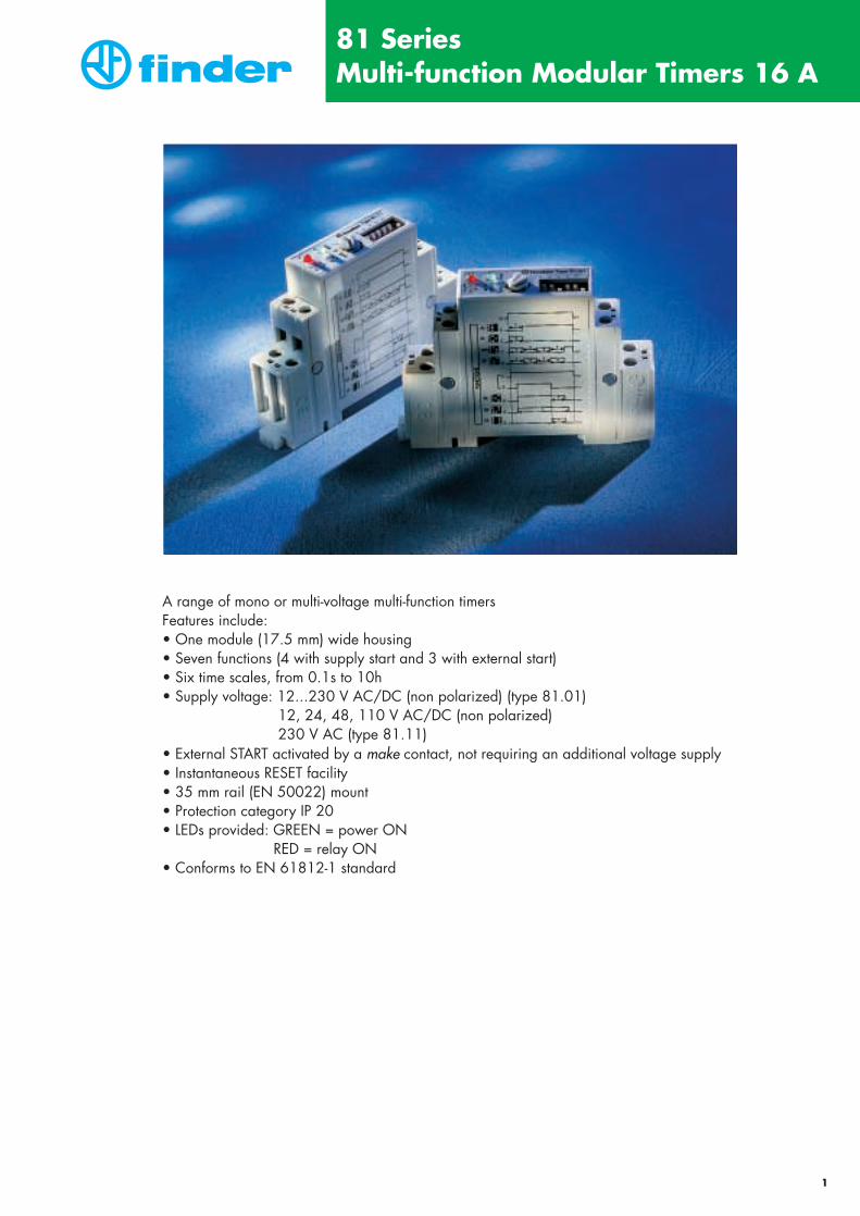
The (C) indicated in the diagrams refers to the position of the NO contact.
NO contactpositionTimingLED**
green
none
in progress
in progress
none
U = Supply Voltage
S = START
C = Relay Contact (NO)
open
open
closed
closed
openTimed Instantaneous*
Contact
closed DIP switch
up
down
open closed
21 - 24*
21 - 22*
21 - 22*
21 - 22*
21 - 22*
21 - 24*
21 - 24*
21 - 24*
15 - 18 15 - 16 25 -28* 25 - 26*
15 - 18 15 - 1625 - 28* 25 - 26*15 - 16 15 - 1825 - 26* 25 - 28*
15 - 16 15 - 1825 - 26* 25 - 28*
* 25-26-28 only for type 87.02 with 2 timed contacts. 21-22-24 only for type 87.02 with 1 instantaneous contact (+1 timed)positioning the front DIP switch.
** The LED on type 87.61 is illuminated when supply voltage is supplied to timer.
wiring diagram without external START
Functions
Multi-functionwiring diagram without external START
Types87.01and
87.02
** Type 87.02: regulatedusing an externalpotentiometer (10 kΩ).
NB.: position thepotentiometeron “zero”.
** Type 87.02: regulatedusing an externalpotentiometer (10 kΩ).
NB.: position thepotentiometer on “zero”.
* A voltage other than thesupply voltage can beapplied to the commandSTART (B1).
(AI) ON delay.Apply power to timer. Contact transfers after preset time has elapsed. Reset occurs when power is removed.T
U
Ct<T
(DI) ON pulse.Apply power to timer. Contact transfers immediately. After preset time has elapsed, contact returns to original position.T
U
Ct<T
(GI) Fixed pulse (0.5s) delayed.Apply power to timer. Contact transfers after preset time has elapsed. Reset occurs after a fixed time of 0.5s.
0.5sT
U
C
(SW) Symmetrical recycler: pulse start.Apply power to timer. First transfer of contact occurs as soon aspower is applied. The timer now cycles between ON and OFFas long as power is applied. The ratio is 1:1 (time off = time on).
T T T T
U
Ct<T
(BE) OFF delay: timing on START release (internal start).Power must be applied at all times to timer. On closure of normallyopen control Signal Switch, the output contact transfers and remainsin that position. When the Signal Switch is reopened, the desired delay begins. After preset time has elapsed, the contact returns to theoriginal position.
T
U
S
t<TC
Tt<T
(CE) ON and OFF delay (external start).On closure of the normally open control Signal Switch, the desired delaybegins. After the preset time has elapsed the output contact transfers and remains in that position. When the Signal Switch is reopened, thedesired delay begins again. After the preset time has elapsed, the contactreturns to the original position.
T
U
C
T t<TT
S
(DE) ON pulse: timing on START pulse.Power must be applied at all times to timer. On momentary or main-tained closure of a normally open control Signal Switch, the outputcontact transfers. After the desired time has elapsed, the contact returnsto the original position.TT
U
S
t<TC
(EE) OFF pulse: timing on START release.Power must be applied at all times to timer. On opening a normallyopen control Signal Switch, the output contact transfers. After the desired time has elapsed, the contact returns to the original position.T
U
S
TC
t<T
Permanently ON.Selecting the function ON when power is applied to the relay thefirst contact transfers immediately and remains in that position.
U
ON
C
Permanently OFF.The contact returns to the original position when the OFF function isselected.
U
OFF
C
A2 18 16
N/–
A1 15
L/+
B1
26
25
Z1 Z2 2822)***(24
**
(21)***
*A2 18 16
N/–
A1 15
L/+
B1
26
25
Z1 Z2 2822)***(24
**
(21)***
*
S

87 SeriesModular Timers 5 - 8 A
31
Functions
wiring diagram without external START
Asymmetricalrecycler
Functionswiring diagram with external START
wiring diagram with external START
Types
87.11
87.21
87.31
87.6187.62
87.82
87.41
87.91
DIP-Switch
DIP-Switch
DIP-Switch
DIP-Switch
Functionswiring diagram without external START
T
U
Ct<T
T
U
Ct<T
T T T T
U
Ct<T
T Tu=∼ 60 ms
U
∆
T
U
S
t<TC
Tt<T
T1 T2
U
S
Ct<TT1
T1 T1T2
U
S
Ct<TT2
T1 T2
U
CT1 T2 t<T
T1 T2
U
CT1 T2 t<T
T TC
U
(AI) ON delay.Apply power to timer. Contact transfers after preset time has elapsed. Reset occurs when power is removed.
(DI) ON pulse.Apply power to timer. Contact transfers immediately. After preset time has elapsed, contact returns to original position.
(SW) Symmetrical recycler: pulse start.Apply power to timer. First transfer of contact occurs as soon aspower is applied. The timer now cycles between ON and OFFas long as power is applied. The ratio is 1:1 (time off = time on).
(BE) OFF delay: timing on START release (internal start).Power must be applied at all times to timer. On closure of normallyopen control Signal Switch, the output contact transfers and remainsin that position. When the Signal Switch is reopened, the desired delay begins. After preset time has elapsed, the contact returns to theoriginal position.
(BI) True OFF delay (power OFF).Apply power to timer (Tmin = 300ms). Contact transfers immediately. Reset occurs when power is removed after preset time elapsed.
(SD) Star - delta.Apply power to timer. Closure of the star contact ( ) occurs immediately. After preset time has elapsed the star contact ( ) returns to the original position. After a fixed time of ~60 ms the delta contact ( ∆ ) closed and remains in that position.
(LI) Asymmetrical recycler pulse start.Apply power to timer. First transfer of contact occurs as soon as poweris applied. The timer now cycles between ON and OFF as long as power is applied. The cycles are not equal (time off = time on).
(PI) Asymmetrical recycler pause start.Apply power to relay. First transfer of contact occurs as soon as power is applied. The timer now cycles between OFF and ON as long as power is applied. The cycles are not equal (time off = time on).
(LE) Asymmetrical recycler pulse start (external start).On closure of the normally open control Signal Switch the first transfer of contact occurs. The timer now cycles between ON and OFF.The cycles are not equal (time off = time on).
(PE) Asymmetrical recycler pause start (external start).On closure of the normally open control Signal Switch the first transfer of contact occurs. The timer now cycles between OFF and ON .The cycles are not equal (time off = time on)
A2 18 16N/–
A1 15
L/+
A2 18 28N/–
A1 17
L/+
A2 18 16N/–
A1 15
L/+
B1
S*
A2 18 16N/–
A1 15
L/+
B1
A2 18 16N/–
A1 15
L/+
B1
S*

87 SeriesModular Timers 5 - 8 A
32
TYPE 87.01INTERNAL STARTFUNCTIONS: AI,DI,GI,SW,ON,OFF
TYPE 87.11-87.21-87.31-87.61INTERNAL STARTFUNCTIONS: AI, BI, DI, SW
TYPE 87.82INTERNAL STARTFUNCTIONS: SD
TYPE 87.41*EXTERNAL STARTFUNCTIONS: BE
TYPE 87.91INTERNAL STARTFUNCTIONS: LI, PI
TYPE 87.91*EXTERNAL STARTFUNCTIONS: LE, PE
TYPE 87.01*EXTERNAL STARTFUNCTIONS: BE, CE, DE, EE
TYPE 87.02INTERNAL STARTFUNCTIONS: AI,DI,GI,SW,ON,OFF
TYPE 87.02*EXTERNAL STARTFUNCTIONS: BE, CE, DE, EE
* The functions with external start (B1) may be activated using a different voltage from that used for the supply voltage.Example: A1 - A2 = 230 V AC
B1 - A2 = 24 V AC
TYPE 87.02:
The 1st contact (terminal numbers 15 - 16 - 18) is always timed according to the function selected.
The 2nd contact is:
- timed in the same way as the 1st contact only if the selector switch is set in the following position: In this case terminals 25 - 26 - 28 must be used.
- instantaneous: In this case terminals 21 - 22 - 24 must be used.
A (10 KΩ) potentiometer may be connected between terminals Z1 and Z2 for external timer regulation.Set the potentiometer to zero.
WIRING DIAGRAMS
TYPE OF TEST REFERENCE STANDARDELECTROSTATIC DISCHARGE - contact discharge EN 61000-4-2 8 kV
- air discharge 8 kV
RADIO-FREQUENCY ELECTROMAGNETIC FIELD (80 ÷ 1000 MHz) ENV 50140 (IEC 1000-4-3) 10 V/m
FAST TRANSIENTS (burst) (5-50 ns, 5 kHz) on Supply terminals EN 61000-4-4 6 kV
SURGES (1.2/50 µs) on Supply terminals
- common mode EN 61000-4-5 4 kV
- differential mode —
RADIO-FREQUENCY COMMON MODE (0.15 ÷ 80 MHz) ENV 50141 (IEC 1000-4-6) 10 Von Supply terminals
RADIATED AND CONDUCTED EMISSION EN 55022 class B
EMC SPECIFICATIONS
Z1 Z2
# #A2 18 16
N/–
A1 B1 15
L/+
A2 18 16
N/–
A1 B1 15
L/+
A2
N/–
A1 B1
L/+
18 16
15
28 (24)*
26 (22)*
(21)*25
Z1 Z2
L/+
B1
A2
N/–
A1
18 16
15
28 (24)*
(21)*25
26 (22)*
A2 18 16
N/–
A1 15
L/+
B1
Start Start
A2 18 16
N/–
A1 15
L/+
A2 18 28
N/–
A1 17
L/+
Start
A2 18 16
N/–
A1 15
L/+
B1
A2 18 16
N/–
A1 15
L/+
B1
Start
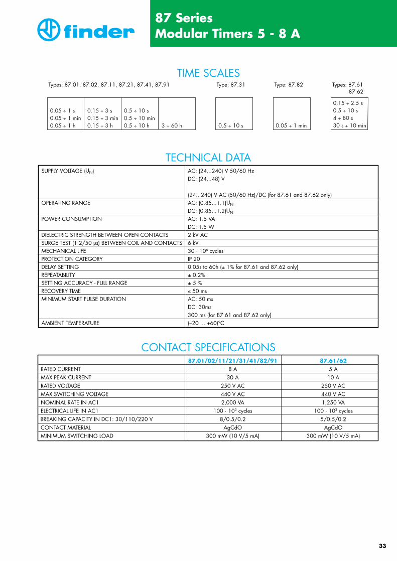
SUPPLY VOLTAGE (UN) AC: (24...240) V 50/60 HzDC: (24...48) V
(24...240) V AC (50/60 Hz)/DC (for 87.61 and 87.62 only)OPERATING RANGE AC: (0.85...1.1)UN
DC: (0.85...1.2)UN
POWER CONSUMPTION AC: 1.5 VADC: 1.5 W
DIELECTRIC STRENGTH BETWEEN OPEN CONTACTS 2 kV ACSURGE TEST (1.2/50 µs) BETWEEN COIL AND CONTACTS 6 kVMECHANICAL LIFE 30 · 106 cycles PROTECTION CATEGORY IP 20DELAY SETTING 0.05s to 60h (± 1% for 87.61 and 87.62 only)REPEATABILITY ± 0.2%SETTING ACCURACY - FULL RANGE ± 5 %RECOVERY TIME ≤ 50 msMINIMUM START PULSE DURATION AC: 50 ms
DC: 30ms300 ms (for 87.61 and 87.62 only)
AMBIENT TEMPERATURE (–20 ... +60)°C
87.01/02/11/21/31/41/82/91 87.61/62RATED CURRENT 8 A 5 AMAX PEAK CURRENT 30 A 10 ARATED VOLTAGE 250 V AC 250 V ACMAX SWITCHING VOLTAGE 440 V AC 440 V ACNOMINAL RATE IN AC1 2,000 VA 1,250 VAELECTRICAL LIFE IN AC1 100 · 103 cycles 100 · 103 cyclesBREAKING CAPACITY IN DC1: 30/110/220 V 8/0.5/0.2 5/0.5/0.2CONTACT MATERIAL AgCdO AgCdOMINIMUM SWITCHING LOAD 300 mW (10 V/5 mA) 300 mW (10 V/5 mA)
TIME SCALES
TECHNICAL DATA
CONTACT SPECIFICATIONS
Types: 87.01, 87.02, 87.11, 87.21, 87.41, 87.91 Type: 87.31 Type: 87.82 Types: 87.6187.62
87 SeriesModular Timers 5 - 8 A
33
0.05 ÷ 1 s0.05 ÷ 1 min0.05 ÷ 1 h
0.15 ÷ 3 s0.15 ÷ 3 min0.15 ÷ 3 h
0.5 ÷ 10 s0.5 ÷ 10 min0.5 ÷ 10 h 3 ÷ 60 h 0.5 ÷ 10 s 0.05 ÷ 1 min
0.15 ÷ 2.5 s0.5 ÷ 10 s4 ÷ 80 s30 s ÷ 10 min

Example: 87 series 8 A multi-function timer, 1 CO contact, with (24 … 240) V AC (50/60)Hz and (24…48) V DC supply.
Supply voltage24…48 V DC24…240 V AC
240 = 24…240 V AC/DC (for 87.61 and 87.62 only)
240 = Supply version0 = AC (50/60 Hz)/DC
Type0 = Multi-function (AI, BE, CE, DI, DE, EE, GI, SW, ON, OFF)1 = ON delay (AI)2 = ON pulse (DI)3 = Symmetrical recycler: pulse start (SW)4 = OFF delay: timing on START release (internal start) (BE)6 = True OFF delay (power OFF) (BI) 8 = Star - delta (SD)9 = Asymmetrical recycler (LI, LE, PI, PE)
No. of contact1 = 1 CO2 = 2 CO for
87.02, 87.622 = 2 NO for 87.82
Series
8 7 2 4 00 1 0 000 0
ORDERING INFORMATION
87 SeriesModular Timers 5 - 8 A
s s s min min min h h h h0.05 0.15 0.5 0.05 0.15 0.5 0.05 0.15 0.5 3
1 3 10 1 3 10 1 3 10 60• • • • • • • • • •• • • • • • • • • •
• • • • • • • • • •• • • • • • • • • •• • • • • • • • • •• • • • • • • • • •• • • • • • • • • •• • • • • • • • • •
• • • • • • • • • •• • • • • • • • • •
•• • • • • • • • • •
0.15 0.072.5 1.3
•
• • • • • • • • • •• • • • • • • • • •
• • • • • • • • • •• • • • • • • • • •
Type FunctionCode
Function
Time scales
87.01/87.02
87.1187.2187.3187.41
87.6187.6287.82
87.91
A IBE
CEDIDEEEGISWONOFFAIDI
SWBE
BI
SD
–LILE
PIPE
ON delayOFF delay: timing on START release (internal start)ON and OFF delay (external start)ON pulseON pulse: timing on START pulseOFF pulse: timing on START releaseFixed pulse (0,5s) delayedSymmetrical recycler: pulse startPermanently ONPermanently OFFON delayON pulseSymmetrical recycler: pulse startOFF delay: timing on START release (internal start)True OFF delay (power OFF)True OFF delay (power OFF)Star - deltaTU = (50…65) msAsymmetrical recycler:Asymmetrical recycler pulse startAsymmetrical recycler pulse start (external start)Asymmetrical recycler pause startAsymmetrical recycler pause start (external start)
• •
34

ZFT
020304G
B -
I/00
- St
ampe
ria A
rtisti
ca N
azio
nale
- To
rino
- Prin
ted
in It
aly
S.P.R.L. FINDER BELGIUM B.V.B.A.Rue Marcel Grünerstraat, 16B - 1080 BRUXELLES - BRUSSELTel. +32/2/4118581 - 4118836Fax +32/2/4119166
FINDER (SCHWEIZ) AGIndustriestrasse 1aPostfach 23CH - 8157 DIELSDORF (ZH)Tel. +41(0) 1/8 85 30 10Fax +41(0) 1/8 85 30 20
FINDER RELAYS, INC.4465 Commerce Drive, Suite: 103Buford, GA 30518 - U.S.A.Tel. +1/770/271-4431Fax +1/770/271-7530
FINDER GmbHEisenstrasse 30D - 65428 RÜSSELSHEIMTel. +49 (0) 61 42/87 70Fax +49 (0) 61 42/8 77 77
FINDER RELAIS NEDERLANDPropellerstraat 1 - 5NL - 1059 CB AMSTERDAMTel. +31/20/6156557Fax +31/20/6178992
FINDER RELAIS VERTRIEBS GmbHAspangbahnstraße 2A - 2361 LAXENBURGTel. +43/2236/86 41 36 - 0Fax +43/2236/86 41 36 36
FINDER P.L.C.Opal Way - Stone Business ParkSTONE, STAFFORDSHIRE,ST15 0SS - UKTel. +44/1785/818100Fax +44/1785/815500
ORDEM E PROGRESSO
FINDER COMPONENTES LTDa.Rua Olavo Bilac, 315BAIRRO: SANTO ANTONIOSAO CAETANO DO SUL - SAO PAULOCEP 09530260 - BRASILTel. +55/11/7690 1550Fax +55/11/4227 4313
FINDER FRANCE SarlAvenue d'Italie - BP 40Zone Ind. du Pré de la GardeF - 73300 ST. JEAN DE MAURIENNE CédexTel. +33/4 79 83 27 27Fax +33/4 79 59 80 04
FINDER SpAVia Drubiaglio, 14I - 10040 ALMESE (TO)Tel. +39/011.934 62 11Fax +39/011.935 90 79
®
http://www.findernet.com
FINDER reserves the right to alter characteristics at any time without notice.FINDER assumes no liability for damage to people or things, caused as a result ot the wrong or application of its products.