Embed Size (px)
Citation preview
Technical Committee on Fundamentals of Combustion Systems Hazards
AGENDA
May 22-23, 2012
Southern Company Birmingham, AL
1. Chair’s welcome, call to order, and opening remarks at 8:00 a.m. CDT. 2. Self-Introduction of Committee Members and Guests 3. Approval of Minutes from the March 2010 ROC Meeting in Tampa, FL. The minutes
are posted on the NFPA 85 document information page, www.nfpa.org/85, by clicking on the “Archived Revision Information” link.
4. Staff Liaison Report A. New Document Revision Process B. Revision Cycle Review and timeline (Attachment A) 5. Old Business A. Held items from last edition (Attachment B) B. Gas Line Purging Task Group - The task force scope is to develop commissioning
requirements that clearly delineate the equipment and piping covered by NFPA 85 and safe procedures for removing or charging gas into piping and equipment. Members of the task group are: B. Baesel; T. Jablkowski; R. Kleen; F. Switzer; and D. Mason. NFPA Staff Note: The task group was established before the development and issuance of NFPA 56(PS), Standard for Fire and Explosion Prevention During Cleaning and Purging of Flammable Gas Piping Systems.
C. Mr. Kleen reported two items that he requests the TC consider in the next revision cycle. See Attachment C for details.
6. New Business A. Review BCS-FUN Public Input received to date (Attachment D) B. NFPA Editorial Requests. (Attachment E) C. Referenced Documents – In their ROC meeting, the Technical Correlating
Committee (TCC) requested that NFPA Staff generate lists of documents referenced in each chapter and review with the TC chair to determine if additional review by the TC is needed to insure that the referenced documents are appropriate and applicable. The documents referenced in chapter 4 are: NFPA 30, NFPA 54, ASME B31.1, ASME B31.3 (section 4.10) and CGA G-2.1 (subsection 4.16.3).
D. Requirement for burner management system to be limited to a single boiler or HRSG (Attachment F) The chairman requests the committee review section 4.11.7.4 to determine if any modification is needed for the next edition.
E. Definitions 3.3.159.11 and 3.3.159.12 (Attachment G) The chairman requests the committee review these definitions because the terms don’t appear to be in use in the Code.
F. Annex material on flue gas analyzers (Attachment H) The chairman requests the committee review the annex sections A.5.3.4.6.3, A.6.4.2.3.4.6(2), and A.7.6.2.1.1(10) to discuss possible recommendations to the SBB, MBB, and FBB committees respectively.
7. Other Items? 8. Date/Location of Next Meeting. The next meeting will be the First Draft Report
meeting. 9. Adjournment.
Attachment A: NFPA F2014 Revision Cycle
Process
StageProcess Step Dates for TC
Dates for TC
with CC
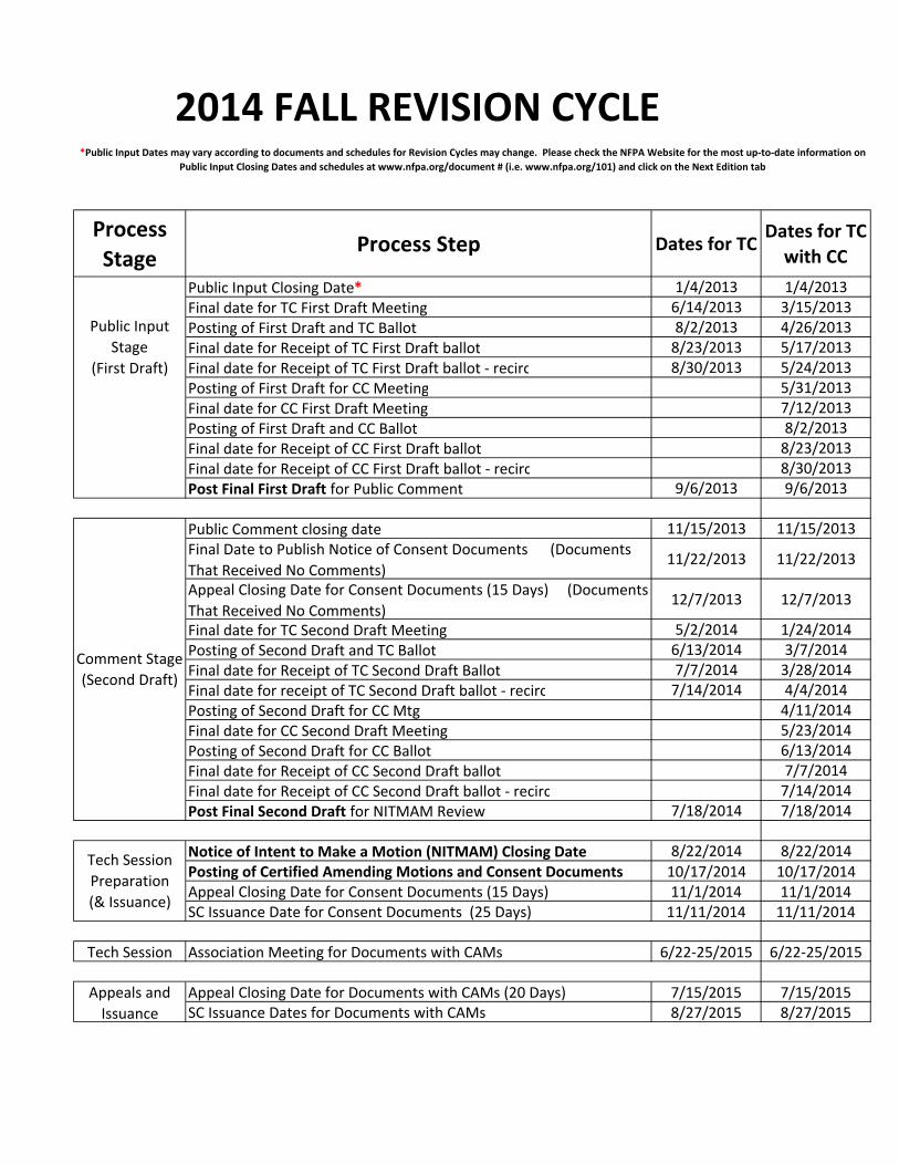
Public Input Closing Date* 1/4/2013 1/4/2013
Final date for TC First Draft Meeting 6/14/2013 3/15/2013
Posting of First Draft and TC Ballot 8/2/2013 4/26/2013
Final date for Receipt of TC First Draft ballot 8/23/2013 5/17/2013
Final date for Receipt of TC First Draft ballot ‐ recirc 8/30/2013 5/24/2013
Posting of First Draft for CC Meeting 5/31/2013
Final date for CC First Draft Meeting 7/12/2013
Posting of First Draft and CC Ballot 8/2/2013
Final date for Receipt of CC First Draft ballot 8/23/2013
Final date for Receipt of CC First Draft ballot ‐ recirc 8/30/2013
Post Final First Draft for Public Comment 9/6/2013 9/6/2013
Public Comment closing date 11/15/2013 11/15/2013
Final Date to Publish Notice of Consent Documents (Documents
That Received No Comments)11/22/2013 11/22/2013
Appeal Closing Date for Consent Documents (15 Days) (Documents
That Received No Comments)12/7/2013 12/7/2013
Final date for TC Second Draft Meeting 5/2/2014 1/24/2014
Posting of Second Draft and TC Ballot 6/13/2014 3/7/2014
Final date for Receipt of TC Second Draft Ballot 7/7/2014 3/28/2014
Final date for receipt of TC Second Draft ballot ‐ recirc 7/14/2014 4/4/2014
Posting of Second Draft for CC Mtg 4/11/2014
Final date for CC Second Draft Meeting 5/23/2014
Posting of Second Draft for CC Ballot 6/13/2014
Final date for Receipt of CC Second Draft ballot 7/7/2014
Final date for Receipt of CC Second Draft ballot ‐ recirc 7/14/2014
Post Final Second Draft for NITMAM Review 7/18/2014 7/18/2014
Notice of Intent to Make a Motion (NITMAM) Closing Date 8/22/2014 8/22/2014
Posting of Certified Amending Motions and Consent Documents 10/17/2014 10/17/2014Appeal Closing Date for Consent Documents (15 Days) 11/1/2014 11/1/2014SC Issuance Date for Consent Documents (25 Days) 11/11/2014 11/11/2014
Tech Session Association Meeting for Documents with CAMs 6/22‐25/2015 6/22‐25/2015
Appeal Closing Date for Documents with CAMs (20 Days) 7/15/2015 7/15/2015SC Issuance Dates for Documents with CAMs 8/27/2015 8/27/2015
Comment Stage
(Second Draft)
Tech Session
Preparation
(& Issuance)
Appeals and
Issuance
2014 FALL REVISION CYCLE
Public Input
Stage
(First Draft)
*Public Input Dates may vary according to documents and schedules for Revision Cycles may change. Please check the NFPA Website for the most up‐to‐date information on
Public Input Closing Dates and schedules at www.nfpa.org/document # (i.e. www.nfpa.org/101) and click on the Next Edition tab

Attachment B: Items Held From Last Cycle
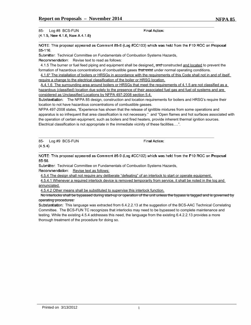
Report on Proposals – November 2014 NFPA 85_______________________________________________________________________________________________85- Log #8 BCS-FUN
_______________________________________________________________________________________________
Technical Committee on Fundamentals of Combustion Systems Hazards,Revise text to read as follows:
4.1.5 The burner or fuel feed piping and equipment shall be designed, and constructed and located to prevent theformation of hazardous concentrations of combustible gases that exist under normal operating conditions.4.1.6* The installation of boilers or HRSGs in accordance with the requirements of this Code shall not in and of itself
require a change to the electrical classification of the boiler or HRSG location.A.4.1.6 The surrounding area around boilers or HRSGs that meet the requirements of 4.1.5 are not classified as a
hazardous (classified) location due solely to the presence of their associated fuel gas and fuel oil systems and areconsidered as Unclassified Locations by NFPA 497-2008 section 5.4.
The NFPA 85 design, construction and location requirements for boilers and HRSG’s require theirlocation to not have hazardous concentrations of combustible gasses.NFPA 497-2008 states, “Experience has shown that the release of ignitible mixtures from some operations andapparatus is so infrequent that area classification is not necessary.” and “Open flames and hot surfaces associated withthe operation of certain equipment, such as boilers and fired heaters, provide inherent thermal ignition sources.Electrical classification is not appropriate in the immediate vicinity of these facilities….”.
_______________________________________________________________________________________________85- Log #9 BCS-FUN
_______________________________________________________________________________________________
Technical Committee on Fundamentals of Combustion Systems Hazards,Revise text as follows:
4.5.4 The design shall not require any deliberate “defeating” of an interlock to start or operate equipment.4.5.4.1 Whenever a required interlock device is removed temporarily from service, it shall be noted in the log and
annunciated.4.5.4.2 Other means shall be substituted to supervise this interlock function.No interlocks shall be bypassed during start-up or operation of the unit unless the bypass is tagged and is governed by
operating procedures.This language was extracted from 6.4.2.2.13 at the suggestion of the BCS-AAC Technical Correlating
Committee. The BCS-FUN TC recognizes that interlocks may need to be bypassed to complete maintenance andtesting. While the existing 4.5.4 addresses this need, the language from the existing 6.4.2.2.13 provides a morethorough treatment of the procedure for doing so.
1Printed on 3/13/2012
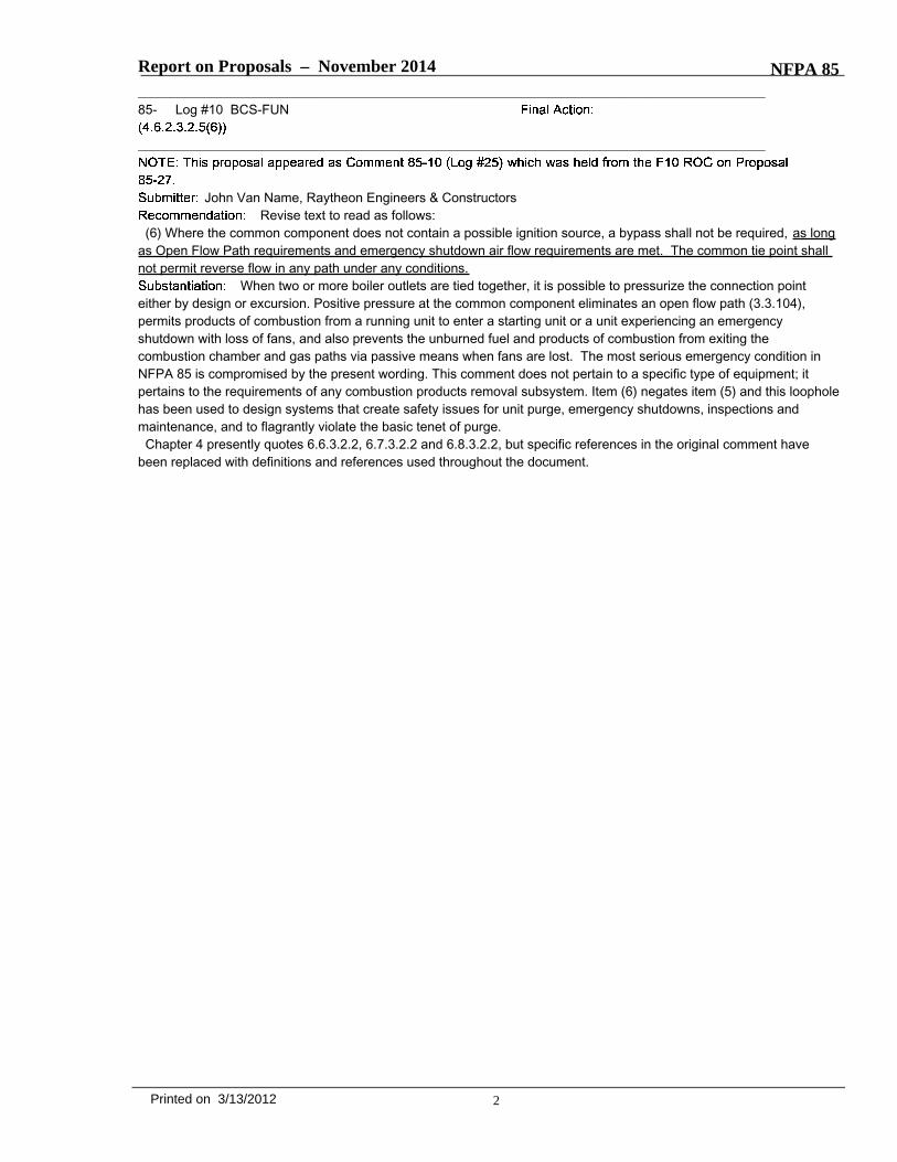
Report on Proposals – November 2014 NFPA 85_______________________________________________________________________________________________85- Log #10 BCS-FUN
_______________________________________________________________________________________________
John Van Name, Raytheon Engineers & ConstructorsRevise text to read as follows:
(6) Where the common component does not contain a possible ignition source, a bypass shall not be required, as longas Open Flow Path requirements and emergency shutdown air flow requirements are met. The common tie point shallnot permit reverse flow in any path under any conditions.
When two or more boiler outlets are tied together, it is possible to pressurize the connection pointeither by design or excursion. Positive pressure at the common component eliminates an open flow path (3.3.104),permits products of combustion from a running unit to enter a starting unit or a unit experiencing an emergencyshutdown with loss of fans, and also prevents the unburned fuel and products of combustion from exiting thecombustion chamber and gas paths via passive means when fans are lost. The most serious emergency condition inNFPA 85 is compromised by the present wording. This comment does not pertain to a specific type of equipment; itpertains to the requirements of any combustion products removal subsystem. Item (6) negates item (5) and this loopholehas been used to design systems that create safety issues for unit purge, emergency shutdowns, inspections andmaintenance, and to flagrantly violate the basic tenet of purge.Chapter 4 presently quotes 6.6.3.2.2, 6.7.3.2.2 and 6.8.3.2.2, but specific references in the original comment have
been replaced with definitions and references used throughout the document.
2Printed on 3/13/2012
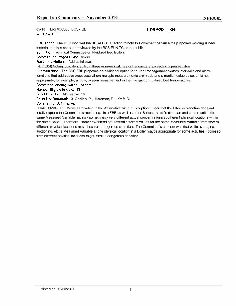
Report on Comments – November 2010 NFPA 85_______________________________________________________________________________________________85-18 Log #CC300 BCS-FBB
_______________________________________________________________________________________________The TCC modified the BCS-FBB TC action to hold this comment because the proposed wording is new
material that has not been reviewed by the BCS-FUN TC or the public.Technical Committee on Fluidized Bed Boilers,
85-30Add as follows:
4.11.3(4) Voting logic derived from three or more switches or transmitters exceeding a preset valueThe BCS-FBB proposes an additional option for burner management system interlocks and alarm
functions that addresses processes where multiple measurements are made and a median value selection is notappropriate, for example, airflow, oxygen measurement in the flue gas, or fluidized bed temperatures.
Affirmative: 103 Chelian, P., Herdman, R., Kraft, D.
DARGUZAS, J.: While I am voting in the Affirmative without Exception; I fear that the listed explanation does nottotally capture the Committee's reasoning. In a FBB as well as other Boilers; stratification can and does result in thesame Measured Variable having - sometimes - very different actual concentrations at different physical locations withinthe same Boiler. Therefore: somehow "blending" several different values for the same Measured Variable from severaldifferent physical locations may obscure a dangerous condition. The Committee's concern was that while averaging,auctioning, etc. a Measured Variable at one physical location in a Boiler maybe appropriate for some activities; doing sofrom different physical locations might mask a dangerous condition.
1Printed on 12/20/2011

Attachment C: Requested Items from R. Kleen
1
Beach, Denise
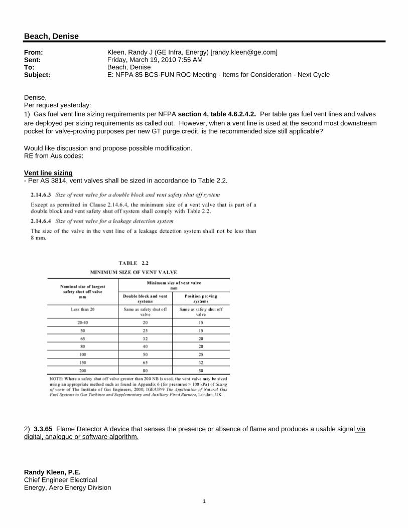
From: Kleen, Randy J (GE Infra, Energy) [[email protected]]Sent: Friday, March 19, 2010 7:55 AMTo: Beach, DeniseSubject: E: NFPA 85 BCS-FUN ROC Meeting - Items for Consideration - Next Cycle
Denise, Per request yesterday: 1) Gas fuel vent line sizing requirements per NFPA section 4, table 4.6.2.4.2. Per table gas fuel vent lines and valves are deployed per sizing requirements as called out. However, when a vent line is used at the second most downstream pocket for valve-proving purposes per new GT purge credit, is the recommended size still applicable?
Would like discussion and propose possible modification. RE from Aus codes:
Vent line sizing - Per AS 3814, vent valves shall be sized in accordance to Table 2.2.
2) 3.3.65 Flame Detector A device that senses the presence or absence of flame and produces a usable signal via digital, analogue or software algorithm.
Randy Kleen, P.E. Chief Engineer Electrical Energy, Aero Energy Division

2
16415 Jacintoport Houston, TX 77015
T 281-864-2873 C 713-249-1593 DC *8-326-2873
Attachment D: New Public Input Received to Date
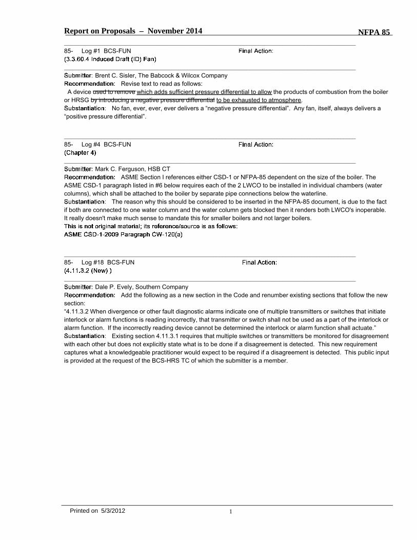
Report on Proposals – November 2014 NFPA 85_______________________________________________________________________________________________85- Log #1 BCS-FUN
_______________________________________________________________________________________________Brent C. Sisler, The Babcock & Wilcox Company
Revise text to read as follows:A device used to remove which adds sufficient pressure differential to allow the products of combustion from the boiler
or HRSG by introducing a negative pressure differential to be exhausted to atmosphere.No fan, ever, ever, ever delivers a “negative pressure differential”. Any fan, itself, always delivers a
“positive pressure differential”.
_______________________________________________________________________________________________85- Log #4 BCS-FUN
_______________________________________________________________________________________________Mark C. Ferguson, HSB CT
ASME Section I references either CSD-1 or NFPA-85 dependent on the size of the boiler. TheASME CSD-1 paragraph listed in #6 below requires each of the 2 LWCO to be installed in individual chambers (watercolumns), which shall be attached to the boiler by separate pipe connections below the waterline.
The reason why this should be considered to be inserted in the NFPA-85 document, is due to the factif both are connected to one water column and the water column gets blocked then it renders both LWCO's inoperable.It really doesn't make much sense to mandate this for smaller boilers and not larger boilers.
_______________________________________________________________________________________________85- Log #18 BCS-FUN
_______________________________________________________________________________________________Dale P. Evely, Southern Company
Add the following as a new section in the Code and renumber existing sections that follow the newsection:“4.11.3.2 When divergence or other fault diagnostic alarms indicate one of multiple transmitters or switches that initiateinterlock or alarm functions is reading incorrectly, that transmitter or switch shall not be used as a part of the interlock oralarm function. If the incorrectly reading device cannot be determined the interlock or alarm function shall actuate.”
Existing section 4.11.3.1 requires that multiple switches or transmitters be monitored for disagreementwith each other but does not explicitly state what is to be done if a disagreement is detected. This new requirementcaptures what a knowledgeable practitioner would expect to be required if a disagreement is detected. This public inputis provided at the request of the BCS-HRS TC of which the submitter is a member.
1Printed on 5/3/2012
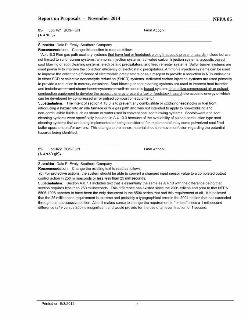
Report on Proposals – November 2014 NFPA 85_______________________________________________________________________________________________85- Log #21 BCS-FUN
_______________________________________________________________________________________________Dale P. Evely, Southern Company
Change this section to read as follows:“A.4.10.3 Flue gas path auxiliary systems that have fuel or feedstock piping that could present hazards include but are
not limited to sulfur burner systems, ammonia injection systems, activated carbon injection systems, acoustic basedsoot blowing or soot cleaning systems, electrostatic precipitators, and fired reheater systems. Sulfur burner systems areused primarily to improve the collection efficiency of electrostatic precipitators. Ammonia injection systems can be usedto improve the collection efficiency of electrostatic precipitators or as a reagent to provide a reduction in NOx emissionsin either SCR or selective noncatalytic reduction (SNCR) systems. Activated carbon injection systems are used primarilyto provide a reduction in mercury emissions. Soot blowing or soot cleaning systems are used to improve heat transferand include water- and steam-based systems as well as acoustic based systems that utilize compressed air or pulsedcombustion equipment to develop the acoustic energy present a fuel or feedstock hazard, the acoustic energy of whichcan be developed by compressed air or pulsed combustion equipment.”
The intent of section 4.10.3 is to prevent any combustible or oxidizing feedstocks or fuel fromintroducing a hazard into an idle furnace or flue gas path and was not intended to apply to non-oxidizing andnon-combustible fluids such as steam or water used in conventional sootblowing systems. Sootblowers and sootcleaning systems were specifically included in A.4.10.3 because of the availability of pulsed combustion type sootcleaning systems that are being implemented or being considered for implementation by some pulverized coal firedboiler operators and/or owners. This change to the annex material should remove confusion regarding the potentialhazards being identified.
_______________________________________________________________________________________________85- Log #22 BCS-FUN
_______________________________________________________________________________________________Dale P. Evely, Southern Company
Change the existing text to read as follows:(b) For protective actions, the system should be able to convert a changed input sensor value to a completed output
control action in 250 milliseconds or less less than 25 milliseconds.Section A.8.7.1 includes text that is essentially the same as A.4.13 with the difference being that
section requires less than 250 milliseconds. This difference has existed since the 2001 edition and prior to that NFPA8506-1998 appears to have been the only document in the 8500 series that had this requirement at all. It is believedthat the 25 millisecond requirement is extreme and probably a typographical error in the 2001 edition that has cascadedthrough each successive edition. Also, it makes sense to change the requirement to “or less” since a 1 milliseconddifference (249 versus 250) is insignificant and would provide for the use of an even fraction of 1 second.
2Printed on 5/3/2012
Attachment E: Editorial Requests
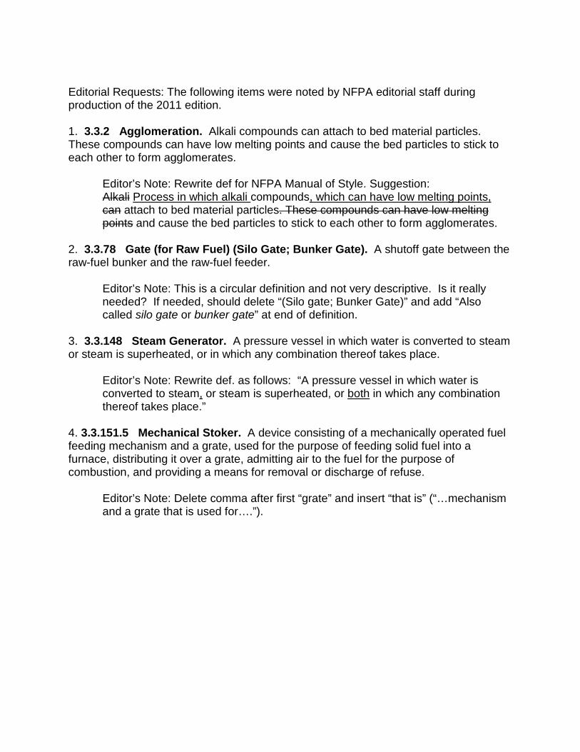
Editorial Requests: The following items were noted by NFPA editorial staff during production of the 2011 edition. 1. 3.3.2 Agglomeration. Alkali compounds can attach to bed material particles. These compounds can have low melting points and cause the bed particles to stick to each other to form agglomerates.
Editor’s Note: Rewrite def for NFPA Manual of Style. Suggestion: Alkali Process in which alkali compounds, which can have low melting points, can attach to bed material particles. These compounds can have low melting points and cause the bed particles to stick to each other to form agglomerates.
2. 3.3.78 Gate (for Raw Fuel) (Silo Gate; Bunker Gate). A shutoff gate between the raw-fuel bunker and the raw-fuel feeder.
Editor’s Note: This is a circular definition and not very descriptive. Is it really needed? If needed, should delete “(Silo gate; Bunker Gate)” and add “Also called silo gate or bunker gate” at end of definition.
3. 3.3.148 Steam Generator. A pressure vessel in which water is converted to steam or steam is superheated, or in which any combination thereof takes place.
Editor’s Note: Rewrite def. as follows: “A pressure vessel in which water is converted to steam, or steam is superheated, or both in which any combination thereof takes place.”
4. 3.3.151.5 Mechanical Stoker. A device consisting of a mechanically operated fuel feeding mechanism and a grate, used for the purpose of feeding solid fuel into a furnace, distributing it over a grate, admitting air to the fuel for the purpose of combustion, and providing a means for removal or discharge of refuse.
Editor’s Note: Delete comma after first “grate” and insert “that is” (“…mechanism and a grate that is used for….”).
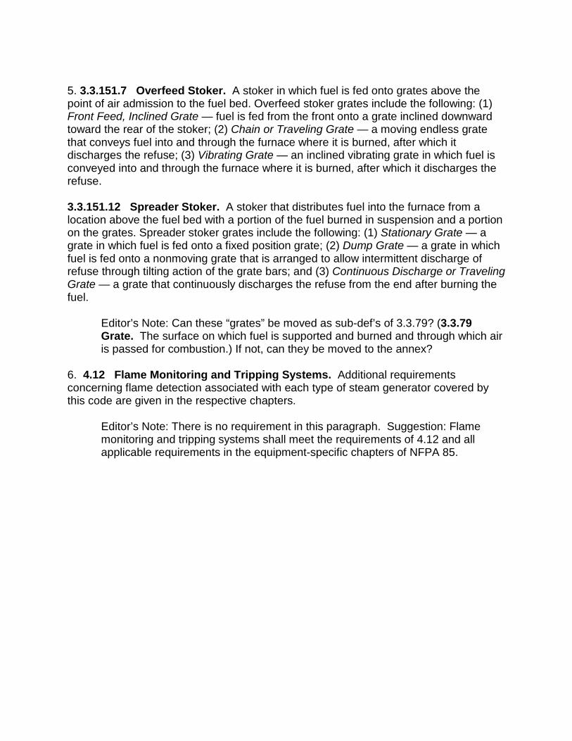
5. 3.3.151.7 Overfeed Stoker. A stoker in which fuel is fed onto grates above the point of air admission to the fuel bed. Overfeed stoker grates include the following: (1) Front Feed, Inclined Grate — fuel is fed from the front onto a grate inclined downward toward the rear of the stoker; (2) Chain or Traveling Grate — a moving endless grate that conveys fuel into and through the furnace where it is burned, after which it discharges the refuse; (3) Vibrating Grate — an inclined vibrating grate in which fuel is conveyed into and through the furnace where it is burned, after which it discharges the refuse. 3.3.151.12 Spreader Stoker. A stoker that distributes fuel into the furnace from a location above the fuel bed with a portion of the fuel burned in suspension and a portion on the grates. Spreader stoker grates include the following: (1) Stationary Grate — a grate in which fuel is fed onto a fixed position grate; (2) Dump Grate — a grate in which fuel is fed onto a nonmoving grate that is arranged to allow intermittent discharge of refuse through tilting action of the grate bars; and (3) Continuous Discharge or Traveling Grate — a grate that continuously discharges the refuse from the end after burning the fuel.
Editor’s Note: Can these “grates” be moved as sub-def’s of 3.3.79? (3.3.79 Grate. The surface on which fuel is supported and burned and through which air is passed for combustion.) If not, can they be moved to the annex?
6. 4.12 Flame Monitoring and Tripping Systems. Additional requirements concerning flame detection associated with each type of steam generator covered by this code are given in the respective chapters.
Editor’s Note: There is no requirement in this paragraph. Suggestion: Flame monitoring and tripping systems shall meet the requirements of 4.12 and all applicable requirements in the equipment-specific chapters of NFPA 85.
7. A.4.3.1 Human error. Statistics indicate that human error is a contributing factor in the majority of explosions. It is important to consider whether the error was a result of any of the following: (1) Lack of understanding of, or failure to use, proper operating procedures, safeguards, and equipment (2) Unfavorable operating characteristics of the equipment or its control (3) Lack of functional coordination of the various components of the steam-generating system and its controls Unfavorable function design. Explosions also can occur as a result of unfavorable functional design. Investigations frequently reveal human error but completely overlook the chain of causes that triggered the operating error. Therefore, the design, installation, and functional objectives of the overall system of components and their controls should be integrated. Consideration should be given to the existing ergonomics that can affect system operation.
Editor’s Note: The NFPA Manual of Style prohibits “run-in headings” in annex material (except definitions where the term is repeated). Are these headings even necessary? Can the committee develop generic lead-in text to make these headings unnecessary?
Attachment F: BMS Dedicated to Single Boiler/HRSG
4.11.7.4 The logic system shall be limited to one boiler or HRSG. From Chairman D. Evely: API asked Mike Polagye in 2010 to explain the reasoning behind this requirement. The apparent reasoning has been: • To ensure a rapid response to trip signals (Polagye). • To reduce the risk of having multiple boilers trip as a result of a problem with a logic system (Polagye). • A concern that if some authorized user is working on the logic system and does something incorrectly (programming error) then there could possibly be an effect on all the boilers on the logic system rather than just one. This wouldn't necessarily be a trip but it could be a hazardous condition (Dressel). • Ease of maintenance or testing. If they are all combined, then whatever precautions or measures taken while working on the logic must be done for all the units rather than just one (Dressel). • Operation of the units would be problematic when changes need to be made and tested with all of the multiple units not operating, which would greatly lessen the redundancy that having multiple boilers provides in the first place (Evely). Don Lueckenotte of Burns and McDonnell for Mike Walz provided the following additional background on this subject: • The per unit requirement appears to have been added with the integration of NFPA 85B, 85D, 85F and 85G into 8502 in 1995 at Article 4-3.2.3.3. The substantiation should have been included with the proposal and should be in NFPA records (Denise – please see if you can locate any substantiation for this from the archives to aid in the discussion in the May meeting). Note that there were several revisions incorporated in 4-3.2.3 during the same document revision. • Standards prior to that revision that we reviewed indicated that the logic systems were simply stated as being required to be independent from all other logic systems. We interpret that requirement to be on a boiler system and within a boiler system. Perhaps it was not so clear to everyone. • As far as applying the requirement for HRSG’s (and fluidized bed boilers), I assume the requirement to have been applied with that integration into the single standard. Single burner boilers have their own exception based on air flow control independency in 4.6.3.2.5.2. • It would be difficult to rationalize a common system for multiple boilers unless there would be no possibility of providing maintenance or programming changes on one boiler with the other boiler in service.
Attachment G: Definitions 3.3.159.11 and 12
3.3.159.11 Safety Shutdown, Low Water Cutout Auxiliary Switch. On single burner boilers, a device that is arranged to effect a safety shutdown of the burner when the water level in the boiler falls to a predetermined low level. 3.3.159.12 Safety Shutdown, Low Water Cutout Switch. A device that is arranged to effect a safety shutdown or master fuel trip when the water level in the boiler or HRSG falls to a predetermined low level.
From Chairman D. Evely: • Doing a word search of both the 2007 and 2011 editions, these terms when
including the word “switch” are found nowhere else in the code. They are used frequently in Chapter 5, but without the word “switch” (Polagye).
• Should the definitions be changed to delete “switch” (Polagye) and relocated in Chapter 3 (Evely)?
• The use of the word “switch” in the definition is being interpreted to mean that all low water cutouts on boilers where NFPA 85 is being enforced have to be switches (Polagye) even though the definitions section of the Code should not in and of itself define requirements (Evely).
Attachment H: Flue Gas Analyzer Annex Text
A.5.3.4.6.3 Analyzers could contain heated elements that exceed the autoignition temperature of many fuels. Zirconium oxide analyzers, commonly used for oxygen analysis, contain an element heated to 1300°F (704°C). This high temperature element presents a potential ignition source to unburned fuel that could be present at startup. Some analyzers are designed to protect the sampled space from the ignition source by providing flashback protection (such as flame arresters in the sample gas path). Analyzers with that protection or that are not heated to autoignition temperature do not present an ignition hazard. A.6.4.2.3.4.6(2) and A.7.6.2.1.1(10) Analyzers could contain heated elements that exceed the autoignition temperature of some fuels. (Remainder of paragraph is identical to A.5.3.4.6.3) From chairman D. Evely:
• These sections are all meant to help explain requirements that read “Permanently installed flue gas analyzers shall not present an ignition source hazard to the flue gas stream being sampled. (SBB)”; “All sources of ignition energy proven off” (MBB); and “The oxygen analyzer and carbon monoxide or combustibles analyzer, if provided, are operating, the carbon monoxide or combustibles indication is at zero, and oxygen indication is at maximum.”
• Per Doug Simmers at Emerson the problems with using flame arrestors (FAs) on oxygen analyzers to provide this type of protection are:
o They only work below a certain temperature which is usually not quantified.
o The FA element will not quench a flame as well once it becomes corroded. o Flame arrestors induce a speed of response delay.
• Emerson prefers powering down the probe, and all other ignition sources upon a loss-of-flame event. The glowing burner refractory will likely present more of a risk of explosion for much longer than a small probe heater up in the back pass.