Embed Size (px)
Citation preview
www.nabertherm.com
MadeinGermany
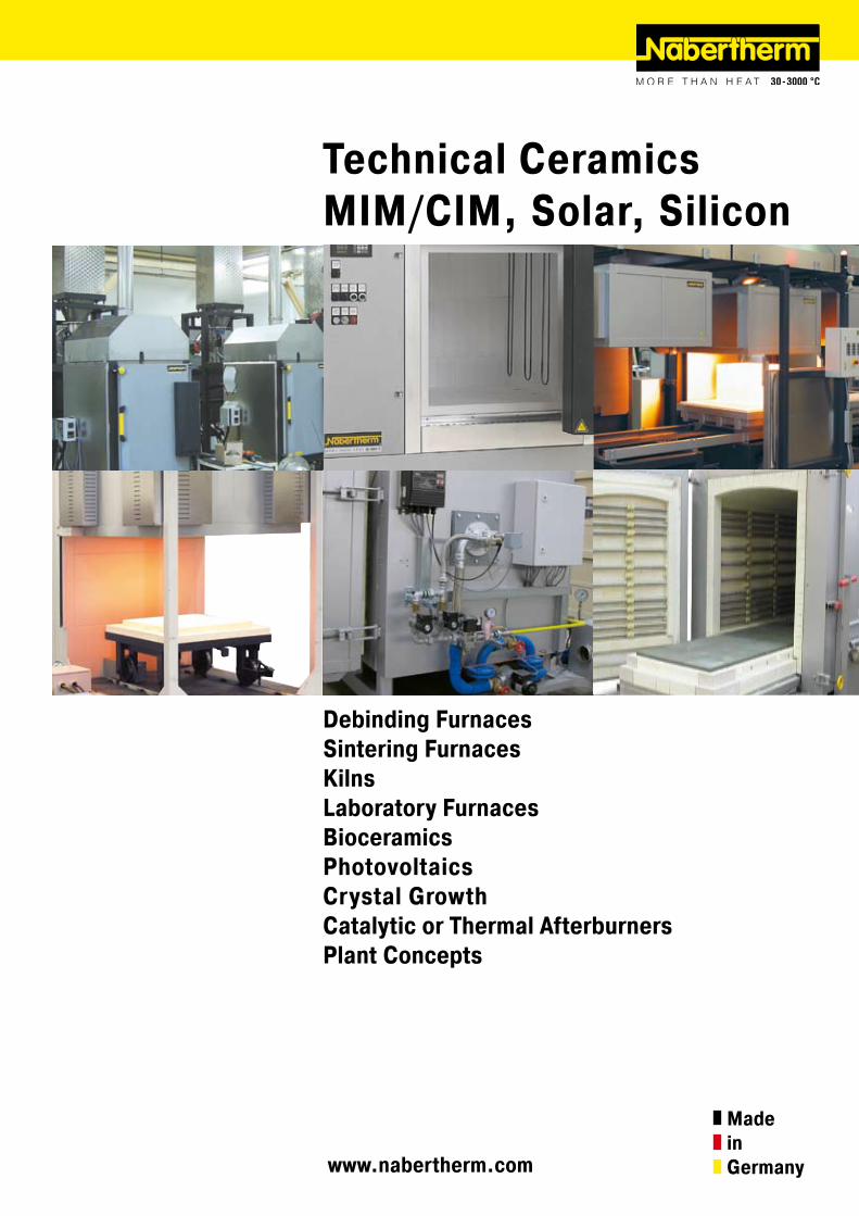
Technical CeramicsMIM/CIM, Solar, Silicon
Debinding FurnacesSintering FurnacesKilnsLaboratory Furnaces BioceramicsPhotovoltaicsCrystal GrowthCatalytic or Thermal AfterburnersPlant Concepts
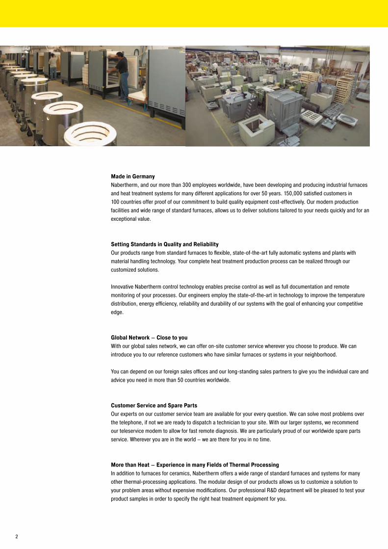
Made in GermanyNabertherm, and our more than 300 employees worldwide, have been developing and producing industrial furnaces and heat treatment systems for many different applications for over 50 years. 150,000 satisfied customers in 100 countries offer proof of our commitment to build quality equipment cost-effectively. Our modern production facilities and wide range of standard furnaces, allows us to deliver solutions tailored to your needs quickly and for an exceptional value.
Setting Standards in Quality and ReliabilityOur products range from standard furnaces to flexible, state-of-the-art fully automatic systems and plants with material handling technology. Your complete heat treatment production process can be realized through our customized solutions.
Innovative Nabertherm control technology enables precise control as well as full documentation and remote monitoring of your processes. Our engineers employ the state-of-the-art in technology to improve the temperature distribution, energy efficiency, reliability and durability of our systems with the goal of enhancing your competitive edge.
Global Network – Close to youWith our global sales network, we can offer on-site customer service wherever you choose to produce. We can introduce you to our reference customers who have similar furnaces or systems in your neighborhood.
You can depend on our foreign sales offices and our long-standing sales partners to give you the individual care and advice you need in more than 50 countries worldwide.
Customer Service and Spare Parts Our experts on our customer service team are available for your every question. We can solve most problems over the telephone, if not we are ready to dispatch a technician to your site. With our larger systems, we recommend our teleservice modem to allow for fast remote diagnosis. We are particularly proud of our worldwide spare parts service. Wherever you are in the world – we are there for you in no time.
More than Heat – Experience in many Fields of Thermal ProcessingIn addition to furnaces for ceramics, Nabertherm offers a wide range of standard furnaces and systems for many other thermal-processing applications. The modular design of our products allows us to customize a solution to your problem areas without expensive modifications. Our professional R&D department will be pleased to test your product samples in order to specify the right heat treatment equipment for you.
�
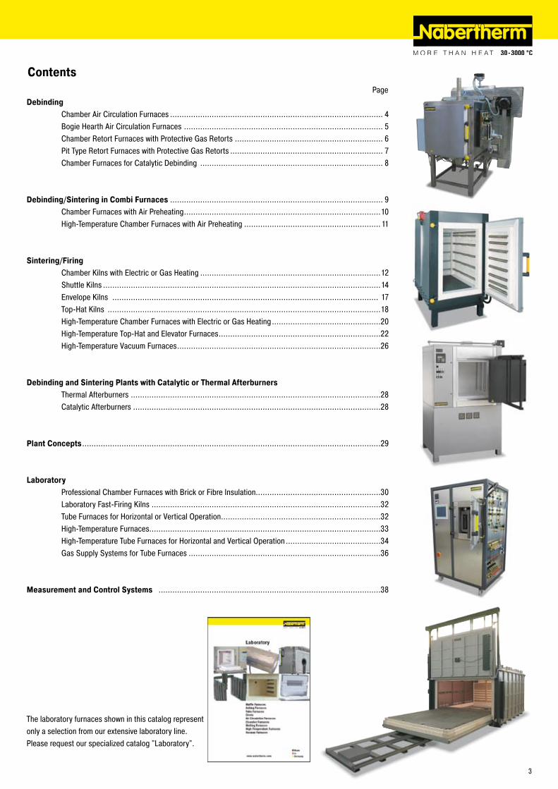
Contents PageDebinding Chamber Air Circulation Furnaces ............................................................................................ 4 Bogie Hearth Air Circulation Furnaces ...................................................................................... 5 Chamber Retort Furnaces with Protective Gas Retorts ................................................................ 6 Pit Type Retort Furnaces with Protective Gas Retorts .................................................................. 7 Chamber Furnaces for Catalytic Debinding ............................................................................... 8
Debinding/Sintering in Combi Furnaces ............................................................................................ 9 Chamber Furnaces with Air Preheating .....................................................................................10 High-Temperature Chamber Furnaces with Air Preheating ...........................................................11
Sintering/Firing Chamber Kilns with Electric or Gas Heating ..............................................................................1� Shuttle Kilns ........................................................................................................................14 Envelope Kilns ................................................................................................................... 17 Top-Hat Kilns ......................................................................................................................18 High-Temperature Chamber Furnaces with Electric or Gas Heating ...............................................�0 High-Temperature Top-Hat and Elevator Furnaces ......................................................................�� High-Temperature Vacuum Furnaces ........................................................................................�6
Debinding and Sintering Plants with Catalytic or Thermal Afterburners Thermal Afterburners ............................................................................................................�8 Catalytic Afterburners ...........................................................................................................�8
Plant Concepts .................................................................................................................................�9
Laboratory Professional Chamber Furnaces with Brick or Fibre Insulation......................................................30 Laboratory Fast-Firing Kilns ...................................................................................................3� Tube Furnaces for Horizontal or Vertical Operation .....................................................................3� High-Temperature Furnaces....................................................................................................33 High-Temperature Tube Furnaces for Horizontal and Vertical Operation .........................................34 Gas Supply Systems for Tube Furnaces ...................................................................................36
Measurement and Control Systems ................................................................................................38
The laboratory furnaces shown in this catalog represent only a selection from our extensive laboratory line. Please request our specialized catalog "Laboratory".
3
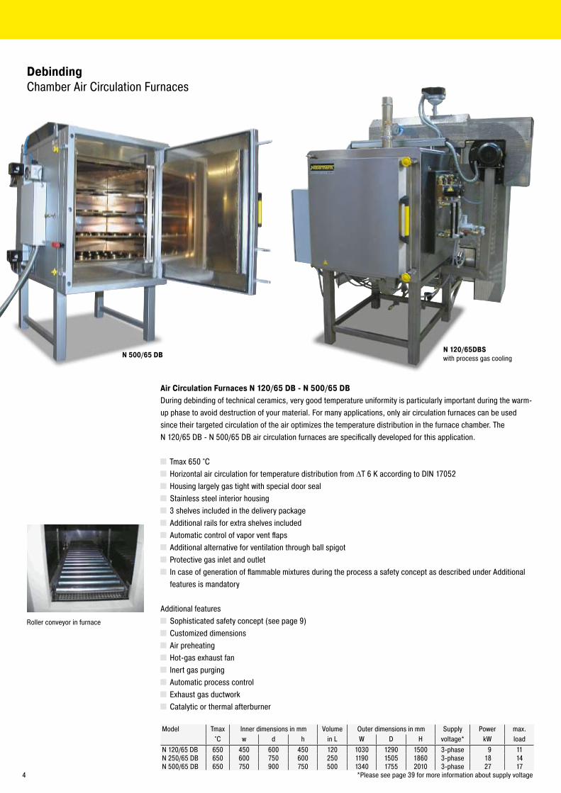
N 500/65 DB
DebindingChamber Air Circulation Furnaces
Air Circulation Furnaces N 120/65 DB - N 500/65 DBDuring debinding of technical ceramics, very good temperature uniformity is particularly important during the warm-up phase to avoid destruction of your material. For many applications, only air circulation furnaces can be used since their targeted circulation of the air optimizes the temperature distribution in the furnace chamber. The N 1�0/65 DB - N 500/65 DB air circulation furnaces are specifically developed for this application.
Tmax 650 °C Horizontal air circulation for temperature distribution from ΔT 6 K according to DIN 1705� Housing largely gas tight with special door seal Stainless steel interior housing 3 shelves included in the delivery package Additional rails for extra shelves included Automatic control of vapor vent flaps Additional alternative for ventilation through ball spigot Protective gas inlet and outlet In case of generation of flammable mixtures during the process a safety concept as described under Additional features is mandatory
Additional features Sophisticated safety concept (see page 9) Customized dimensions Air preheating Hot-gas exhaust fan Inert gas purging Automatic process control Exhaust gas ductwork Catalytic or thermal afterburner
Model Tmax Inner dimensions in mm Volume Outer dimensions in mm Supply Power max. °C w d h in L W D H voltage* kW load
N 1�0/65 DB 650 450 600 450 1�0 1030 1�90 1500 3-phase 9 11N �50/65 DB 650 600 750 600 �50 1190 1505 1860 3-phase 18 14N 500/65 DB 650 750 900 750 500 1340 1755 �010 3-phase �7 17 *Please see page 39 for more information about supply voltage
N 120/65DBS with process gas cooling
Roller conveyor in furnace
4
DebindingBogie Hearth Air Circulation Furnaces
Bogie Hearth Air Circulation Furnaces W 1000/65A - W 10000/85AEspecially for debinding of heavy charges and/or loading outside the furnace, bogie hearth furnaces are recommended. Even the standard furnace achieves a particularlygood temperature distribution of up to ΔT 14 K.
Tmax 650 °C or 850 °C Special wheels so bogie can run on factory floor Three-sided heating, from both sides and from the bogie Vertical air circulation with fans in the furnace roof Sophisticated safety concept (see page 9)
Additional Features Atmosphere box for operation with inert gas Electro-hydraulic lift door Air inlet and outlet system Bogie on rails and/or electrical drive of the bogie Cooling systems Multi-zone control for optimizing the temperature distribution up to ΔT 6 K according to with DIN 1705� Control of vapor vent flaps for fast cooling Customized dimensions of up to �0 m³ furnace volume
Model Tmax Inner dimensions in mm Volume Outer dimensions in mm Power Supply°C w d h in L W D H kW voltage*
W 1000 /65A 650 800 1600 800 1000 1450 �400 �300 4� 3-phaseW 1500 /65A 650 900 1900 900 1500 1550 �750 �400 58 3-phaseW �000 /65A 650 1000 ��00 1000 ��00 1650 3000 �500 77 3-phaseW 3300 /65A 650 1000 3300 1000 3300 1650 4000 �500 90 3-phaseW 5000 /65A 650 1�00 3400 1�00 5000 1850 4100 �700 110 3-phaseW 7500 /65A 650 1400 3800 1400 7500 �050 4500 �900 140 3-phaseW 10000 /65A 650 1600 3900 1600 10000 ��50 4600 3100 ��0 3-phase
W 1000 /85A 850 800 1600 800 1000 1450 �400 �300 4� 3-phaseW 1500 /85A 850 900 1900 900 1500 1550 �750 �400 58 3-phaseW ��00 /85A 850 1000 ��00 1000 ��00 1650 3000 �500 77 3-phaseW 3300 /85A 850 1000 3300 1000 3300 1650 4000 �500 90 3-phaseW 5000 /85A 850 1�00 3400 1�00 5000 1850 4100 �700 110 3-phaseW 7500 /85A 850 1400 3800 1400 7500 �050 4500 �900 140 3-phaseW 10000 /85A 850 1600 3900 1600 10000 ��50 4600 3100 ��0 3-phase
*Please see page 39 for more information about supply voltage
W 1500/65Awith atmosphere box and Rails
Atmosphere boxes on bogie for furnace W 14850
W 10370/65ASwith bogie on Rails
5
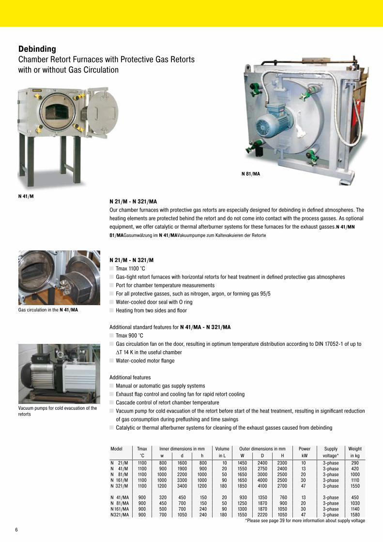
N 41/M
N 81/MA
DebindingChamber Retort Furnaces with Protective Gas Retorts with or without Gas Circulation
N 21/M - N 321/MAOur chamber furnaces with protective gas retorts are especially designed for debinding in defined atmospheres. The heating elements are protected behind the retort and do not come into contact with the process gasses. As optional equipment, we offer catalytic or thermal afterburner systems for these furnaces for the exhaust gasses.N 41/MN
81/MAGasumwälzung im N 41/MAVakuumpumpe zum Kaltevakuieren der Retorte
N 21/M - N 321/M Tmax 1100 °C Gas-tight retort furnaces with horizontal retorts for heat treatment in defined protective gas atmospheres Port for chamber temperature measurements For all protective gasses, such as nitrogen, argon, or forming gas 95/5 Water-cooled door seal with O ring Heating from two sides and floor
Additional standard features for N 41/MA - N 321/MA Tmax 900 °C Gas circulation fan on the door, resulting in optimum temperature distribution according to DIN 1705�-1 of up to ΔT 14 K in the useful chamber
Water-cooled motor flange
Additional features Manual or automatic gas supply systems Exhaust flap control and cooling fan for rapid retort cooling Cascade control of retort chamber temperature Vacuum pump for cold evacuation of the retort before start of the heat treatment, resulting in significant reduction of gas consumption during preflushing and time savings
Catalytic or thermal afterburner systems for cleaning of the exhaust gasses caused from debinding
Gas circulation in the N 41/MA
Vacuum pumps for cold evacuation of the retorts
Model Tmax Inner dimensions in mm Volume Outer dimensions in mm Power Supply Weight°C w d h in L W D H kW voltage* in kg
N �1/M 1100 800 1600 800 10 1450 �400 �300 10 3-phase �90N 41/M 1100 900 1900 900 �0 1550 �750 �400 13 3-phase 4�0N 81/M 1100 1000 ��00 1000 50 1650 3000 �500 �0 3-phase 1000N 161/M 1100 1000 3300 1000 90 1650 4000 �500 30 3-phase 1110N 3�1/M 1100 1�00 3400 1�00 180 1850 4100 �700 47 3-phase 1550
N 41/MA 900 3�0 450 150 �0 930 1350 760 13 3-phase 450N 81/MA 900 450 700 150 50 1�50 1870 900 �0 3-phase 1030N 161/MA 900 500 700 �40 90 1300 1870 1050 30 3-phase 1140N 3�1/MA 900 700 1050 �40 180 1550 ���0 1050 47 3-phase 1580
*Please see page 39 for more information about supply voltage
6
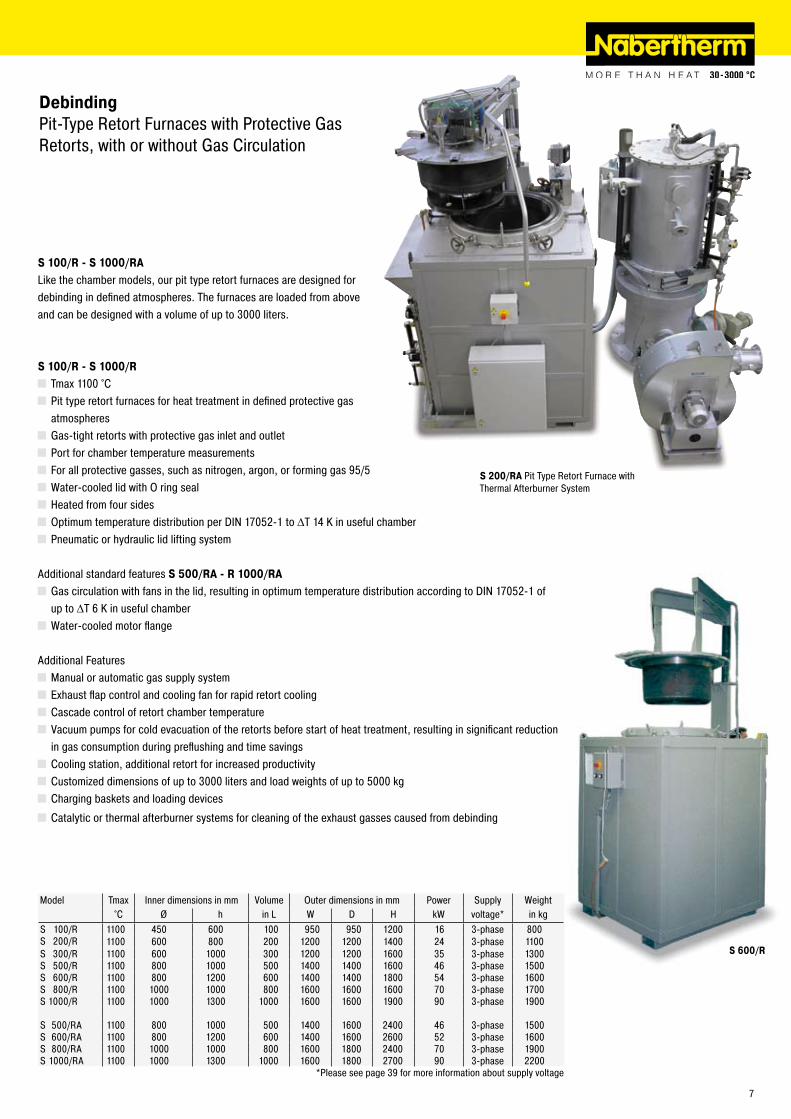
S 600/R
DebindingPit-Type Retort Furnaces with Protective Gas Retorts, with or without Gas Circulation
S 100/R - S 1000/RALike the chamber models, our pit type retort furnaces are designed for debinding in defined atmospheres. The furnaces are loaded from above and can be designed with a volume of up to 3000 liters.
S 100/R - S 1000/R Tmax 1100 °C Pit type retort furnaces for heat treatment in defined protective gas atmospheres
Gas-tight retorts with protective gas inlet and outlet Port for chamber temperature measurements For all protective gasses, such as nitrogen, argon, or forming gas 95/5 Water-cooled lid with O ring seal Heated from four sides Optimum temperature distribution per DIN 1705�-1 to ΔT 14 K in useful chamber Pneumatic or hydraulic lid lifting system
Additional standard features S 500/RA - R 1000/RA Gas circulation with fans in the lid, resulting in optimum temperature distribution according to DIN 1705�-1 of
up to ΔT 6 K in useful chamber Water-cooled motor flange
Additional Features Manual or automatic gas supply system Exhaust flap control and cooling fan for rapid retort cooling Cascade control of retort chamber temperature Vacuum pumps for cold evacuation of the retorts before start of heat treatment, resulting in significant reduction in gas consumption during preflushing and time savings
Cooling station, additional retort for increased productivity Customized dimensions of up to 3000 liters and load weights of up to 5000 kg Charging baskets and loading devices
Catalytic or thermal afterburner systems for cleaning of the exhaust gasses caused from debinding
S 200/RA Pit Type Retort Furnace with Thermal Afterburner System
Model Tmax Inner dimensions in mm Volume Outer dimensions in mm Power Supply Weight°C Ø h in L W D H kW voltage* in kg
S 100/R 1100 450 600 100 950 950 1�00 16 3-phase 800S �00/R 1100 600 800 �00 1�00 1�00 1400 �4 3-phase 1100S 300/R 1100 600 1000 300 1�00 1�00 1600 35 3-phase 1300S 500/R 1100 800 1000 500 1400 1400 1600 46 3-phase 1500S 600/R 1100 800 1�00 600 1400 1400 1800 54 3-phase 1600S 800/R 1100 1000 1000 800 1600 1600 1600 70 3-phase 1700S 1000/R 1100 1000 1300 1000 1600 1600 1900 90 3-phase 1900
S 500/RA 1100 800 1000 500 1400 1600 �400 46 3-phase 1500S 600/RA 1100 800 1�00 600 1400 1600 �600 5� 3-phase 1600S 800/RA 1100 1000 1000 800 1600 1800 �400 70 3-phase 1900S 1000/RA 1100 1000 1300 1000 1600 1800 �700 90 3-phase ��00
*Please see page 39 for more information about supply voltage
7
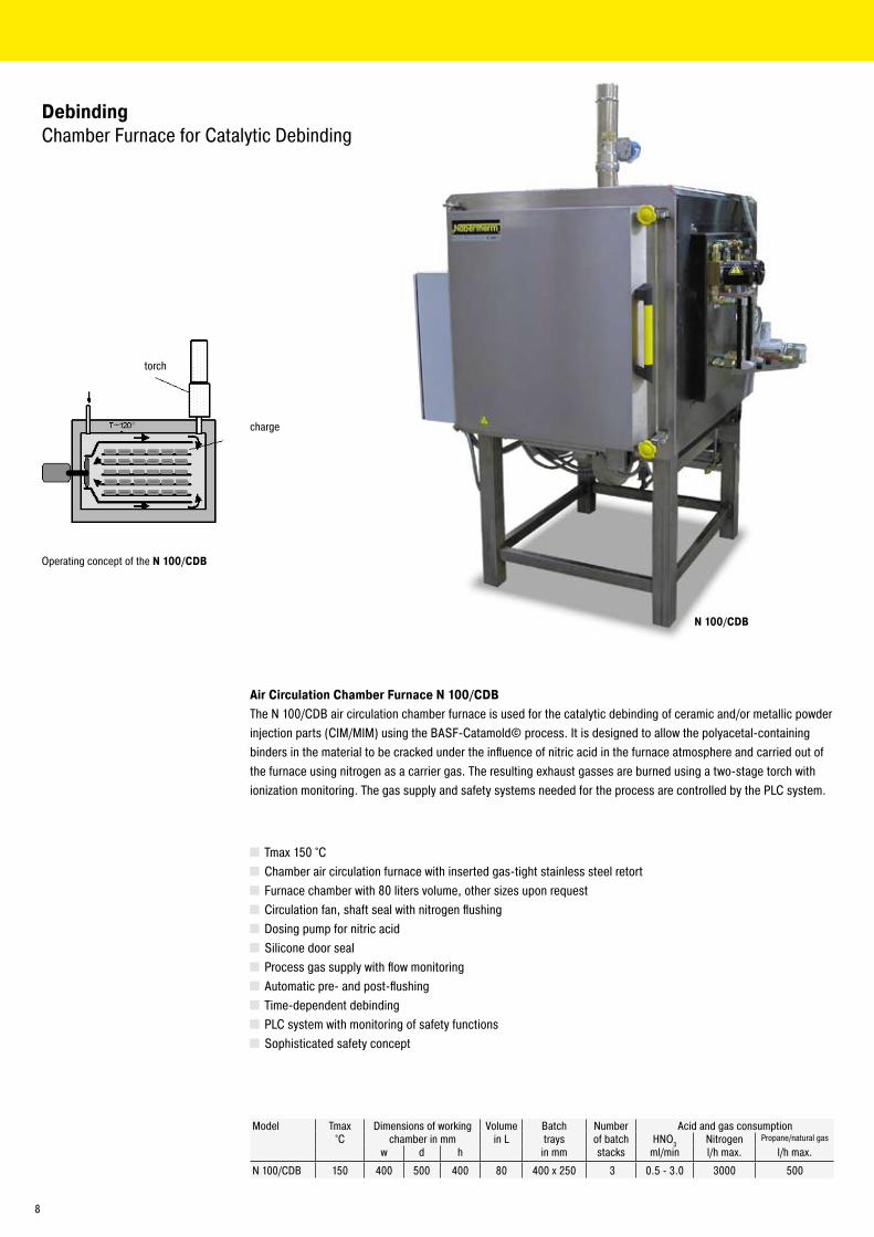
N 100/CDB
DebindingChamber Furnace for Catalytic Debinding
Model Tmax Dimensions of working Volume Batch Number Acid and gas consumption°C chamber in mm in L trays of batch HNO3 Nitrogen Propane/natural gas
w d h in mm stacks ml/min l/h max. l/h max.
N 100/CDB 150 400 500 400 80 400 x �50 3 0.5 - 3.0 3000 500
Air Circulation Chamber Furnace N 100/CDBThe N 100/CDB air circulation chamber furnace is used for the catalytic debinding of ceramic and/or metallic powder injection parts (CIM/MIM) using the BASF-Catamold© process. It is designed to allow the polyacetal-containing binders in the material to be cracked under the influence of nitric acid in the furnace atmosphere and carried out of the furnace using nitrogen as a carrier gas. The resulting exhaust gasses are burned using a two-stage torch with ionization monitoring. The gas supply and safety systems needed for the process are controlled by the PLC system.
Tmax 150 °C Chamber air circulation furnace with inserted gas-tight stainless steel retort Furnace chamber with 80 liters volume, other sizes upon request Circulation fan, shaft seal with nitrogen flushing Dosing pump for nitric acid Silicone door seal Process gas supply with flow monitoring Automatic pre- and post-flushing Time-dependent debinding PLC system with monitoring of safety functions Sophisticated safety concept
Operating concept of the N 100/CDB
charge
torch
8
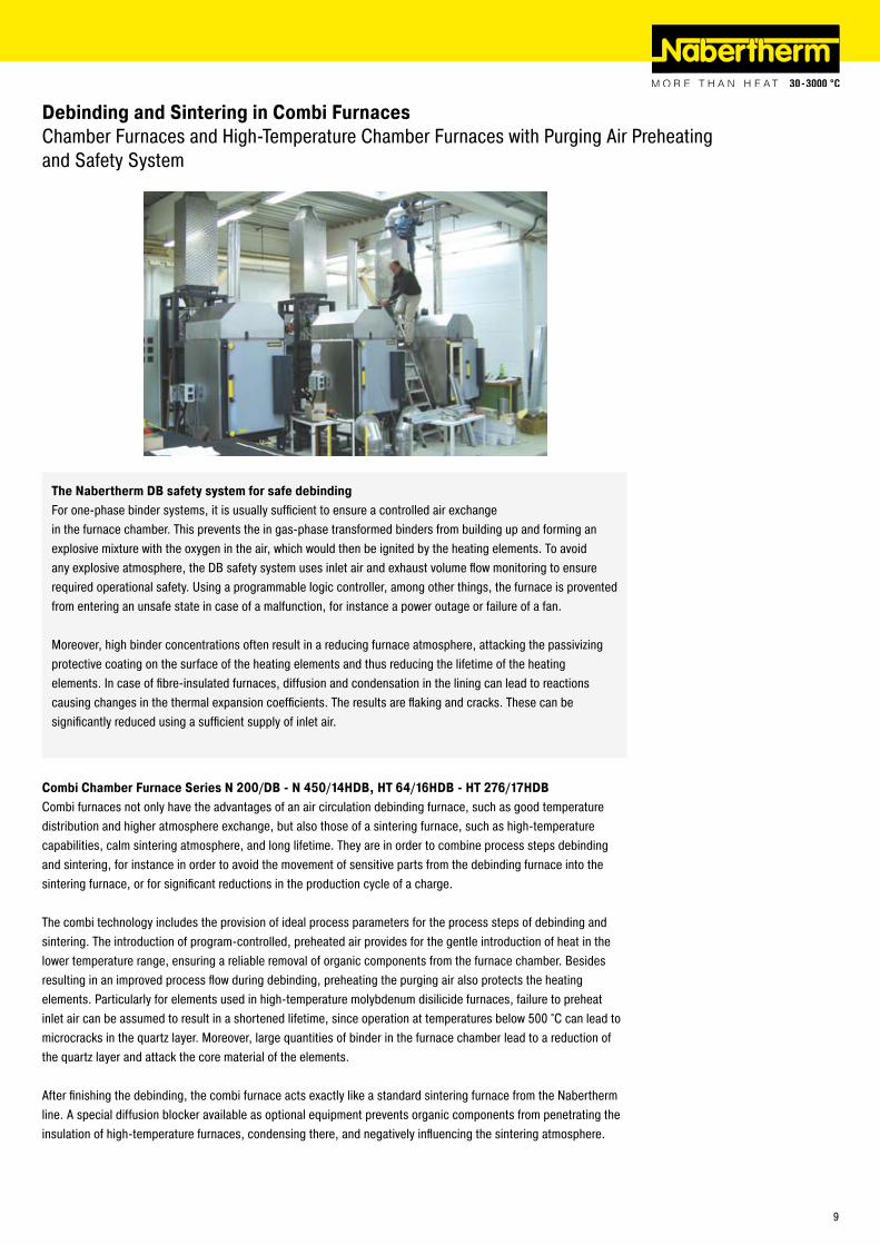
Debinding and Sintering in Combi FurnacesChamber Furnaces and High-Temperature Chamber Furnaces with Purging Air Preheating and Safety System
Combi Chamber Furnace Series N 200/DB - N 450/14HDB, HT 64/16HDB - HT 276/17HDB Combi furnaces not only have the advantages of an air circulation debinding furnace, such as good temperature distribution and higher atmosphere exchange, but also those of a sintering furnace, such as high-temperature capabilities, calm sintering atmosphere, and long lifetime. They are in order to combine process steps debinding and sintering, for instance in order to avoid the movement of sensitive parts from the debinding furnace into the sintering furnace, or for significant reductions in the production cycle of a charge.
The combi technology includes the provision of ideal process parameters for the process steps of debinding and sintering. The introduction of program-controlled, preheated air provides for the gentle introduction of heat in the lower temperature range, ensuring a reliable removal of organic components from the furnace chamber. Besides resulting in an improved process flow during debinding, preheating the purging air also protects the heating elements. Particularly for elements used in high-temperature molybdenum disilicide furnaces, failure to preheat inlet air can be assumed to result in a shortened lifetime, since operation at temperatures below 500 °C can lead to microcracks in the quartz layer. Moreover, large quantities of binder in the furnace chamber lead to a reduction of the quartz layer and attack the core material of the elements.
After finishing the debinding, the combi furnace acts exactly like a standard sintering furnace from the Nabertherm line. A special diffusion blocker available as optional equipment prevents organic components from penetrating the insulation of high-temperature furnaces, condensing there, and negatively influencing the sintering atmosphere.
The Nabertherm DB safety system for safe debindingFor one-phase binder systems, it is usually sufficient to ensure a controlled air exchange in the furnace chamber. This prevents the in gas-phase transformed binders from building up and forming an explosive mixture with the oxygen in the air, which would then be ignited by the heating elements. To avoid any explosive atmosphere, the DB safety system uses inlet air and exhaust volume flow monitoring to ensure required operational safety. Using a programmable logic controller, among other things, the furnace is provented from entering an unsafe state in case of a malfunction, for instance a power outage or failure of a fan.
Moreover, high binder concentrations often result in a reducing furnace atmosphere, attacking the passivizing protective coating on the surface of the heating elements and thus reducing the lifetime of the heating elements. In case of fibre-insulated furnaces, diffusion and condensation in the lining can lead to reactions causing changes in the thermal expansion coefficients. The results are flaking and cracks. These can be significantly reduced using a sufficient supply of inlet air.
9
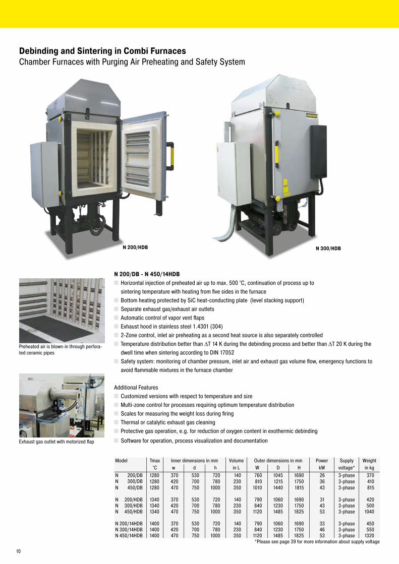
N 200/HDB N 300/HDB
N 200/DB - N 450/14HDB Horizontal injection of preheated air up to max. 500 °C, continuation of process up to sintering temperature with heating from five sides in the furnace
Bottom heating protected by SiC heat-conducting plate (level stacking support) Separate exhaust gas/exhaust air outlets Automatic control of vapor vent flaps Exhaust hood in stainless steel 1.4301 (304) �-Zone control, inlet air preheating as a second heat source is also separately controlled Temperature distribution better than ΔT 14 K during the debinding process and better than ΔT �0 K during the dwell time when sintering according to DIN 1705�
Safety system: monitoring of chamber pressure, inlet air and exhaust gas volume flow, emergency functions to avoid flammable mixtures in the furnace chamber
Additional Features Customized versions with respect to temperature and size Multi-zone control for processes requiring optimum temperature distribution Scales for measuring the weight loss during firing Thermal or catalytic exhaust gas cleaning Protective gas operation, e.g. for reduction of oxygen content in exothermic debinding
Software for operation, process visualization and documentation
Preheated air is blown-in through perfora-ted ceramic pipes
Debinding and Sintering in Combi FurnacesChamber Furnaces with Purging Air Preheating and Safety System
Exhaust gas outlet with motorized flap
Model Tmax Inner dimensions in mm Volume Outer dimensions in mm Power Supply Weight°C w d h in L W D H kW voltage* in kg
N �00/DB 1�80 370 530 7�0 140 760 1045 1690 �6 3-phase 370N 300/DB 1�80 4�0 700 780 �30 810 1�15 1750 36 3-phase 410N 450/DB 1�80 470 750 1000 350 1010 1440 1815 43 3-phase 815
N �00/HDB 1340 370 530 7�0 140 790 1060 1690 31 3-phase 4�0N 300/HDB 1340 4�0 700 780 �30 840 1�30 1750 43 3-phase 500N 450/HDB 1340 470 750 1000 350 11�0 1485 18�5 53 3-phase 1040
N �00 /14HDB 1400 370 530 7�0 140 790 1060 1690 33 3-phase 450N 300 /14HDB 1400 4�0 700 780 �30 840 1�30 1750 46 3-phase 550N 450 /14HDB 1400 470 750 1000 350 11�0 1485 18�5 53 3-phase 13�0
*Please see page 39 for more information about supply voltage
10
HT 64/17HDB
Debinding and Sintering in Combi FurnacesHigh-Temperature Chamber Furnaces with Inlet Air Preheating andSafety System
HT 64/16HDB - HT 276/17HDB Horizontal injection of preheated air up to max. 500 °C, continuation of process up to sintering temperature with heating elements of molybdenum disilicide (MoSi�)
Floor reinforcement with flat stacking support to protect fibre insulation and to support heavy loads
Chain guided parallel moving swivel door for precise operation protecting the collar fibre insulation
Door area amored with stainless steel to avoid burn damage Over temperature limit controller for product and furnace protection Furnace chamber lined with first-class, durable fibre materials Special ceiling construction with high durability Long lasting thermocouple, PtRh-Pt, Type B or Type S Separate exhaust gas and exhaust air flaps Automatic control of vapor vent flaps Exhaust hood in stainless steel 1.4301(304) �-Zone control, inlet air preheating as a second heat source is also separately controlled
Temperature distribution better than ΔT 14 K during the debinding process and better than ΔT �0 K during the dwell time when sintering according to DIN 1705�
Safety system: monitoring of chamber pressure, inlet air and exhaust gas volume flow, emergency functions to avoid flammable mixtures in the furnace chamber
Additional Features Customized versions with respect to temperature and size Multi-zone control for processes requiring optimum temperature distribution Scales for measuring the weight loss during firing Thermal or catalytic exhaust gas purification Protective gas operation, e.g. for reduction of oxygen content in exothermic debinding
Software for operation, process visualization and documentation
Model Tmax Inner dimensions in mm Volume Outer dimensions in mm Power Supply Weight°C w d h in L W D H kW voltage* in kg
HT 64/16HDB 1600 400 400 400 64 10�0 840 1700 �9 3-phase 550HT 160/16HDB 1600 500 550 550 160 1140 10�0 1900 3� 3-phase 800HT �76/16HDB 1600 500 1000 550 �76 1140 1470 1900 49 3-phase 1100
HT 64/17HDB 1750 400 400 400 64 10�0 840 1700 �9 3-phase 550HT 160/17HDB 1750 500 550 550 160 1140 10�0 1900 3� 3-phase 800HT �76/17HDB 1750 500 1000 550 �76 1140 1470 1900 49 3-phase 1100
*Please see page 39 for more information about supply voltage
11
N 300
N 150
N 650
Sintering/FiringChamber Kilns with Electric or Gas Heating
Chamber Furnaces N 100/G - N 2200/14, Electrically HeatedHigh-quality workmanship, attractive design, durability, and excellent temperature distribution – these are the most important quality features of the N 100/G - N ��00/14 chamber furnace. Our extensive standard series addresses most customer needs.
Tmax 900 °C, 1�80 °C, 1340 °C or 1400 °C Five-sided heating with special arrangement of the heating elements for optimum temperature distribution Heating elements on support tubes resulting in long service life of the heating wire Protection of floor heating and flat stacking surface provided by embedded SiC plate in the floor High quality long lasting thermocouple, type S Door safety switch Multi-layer insulation with lightweight refractory bricks and special rear insulation Side walls and door double walled, side walls made of stainless steel (up to N 300..) Controlled air inflow, vapor vent in the kiln ceiling (from N 450 designed as flap) Self-supporting brick ceiling construction, arch-shaped Removable stand (up to N 300…)
Additional Features N 100/G - N 2200/14 Customized dimensions Cooling systems for shortening cycles with manual or fully automatic control gear Automatic vapor vent flap control for better air outflow Stainless steel exhaust gas hoods Thermal or catalytic exhaust gas cleaning Customized kiln furniture Multi-zone control for an optimum temperature distribution
Process documentation by temperature recorder or PC softwareN1500/H with integrated SiC beam structure
1�
Model Tmax Inner dimensions in mm Volume Outer dimensions in mm Power Supply Weight°C w d h in L W D H kW voltage* in kg
N 100 /G 900 400 530 460 100 710 1150 1430 7 3-phase �70N 150 /G 900 450 530 590 150 760 1150 1560 9 3-phase 305N �00 /G 900 500 530 7�0 �00 810 1150 1690 11 3-phase 345N 300 /G 900 550 700 780 300 860 1340 1750 15 3-phase 430N 450 /G 900 600 750 1000 450 1010 1440 1815 �0 3-phase 815N 650 /G 900 700 850 1100 650 11�0 1540 19�5 �6 3-phase 930N 1000 /G 900 800 1000 1�50 1000 1370 1810 �000 40 3-phase 1680N 1500 /G 900 900 1�00 1400 1500 1470 �010 �160 57 3-phase �300N ��00 /G 900 1000 1400 1600 ��00 1570 ��10 �360 75 3-phase �800 N 100 1�80 400 530 460 100 660 1150 1430 9 3-phase �70N 150 1�80 450 530 590 150 710 1150 1560 11 3-phase �90N �00 1�80 500 530 7�0 �00 760 1150 1690 15 3-phase 370N 300 1�80 550 700 780 300 810 1340 1750 �0 3-phase 410N 450 1�80 600 750 1000 450 1010 1440 1815 30 3-phase 815N 650 1�80 700 850 1100 650 11�0 1540 19�5 40 3-phase 930N 1000 1�80 800 1000 1�50 1000 1450 1850 �000 57 3-phase 1800N 1500 1�80 900 1�00 1400 1500 1550 �050 �160 75 3-phase �500N ��00 1�80 1000 1400 1600 ��00 1650 ��50 �360 110 3-phase 3100
N 100 /H 1340 400 530 460 100 690 1170 1430 11 3-phase 315N 150 /H 1340 450 530 590 150 740 1170 1560 15 3-phase 350N �00 /H 1340 500 530 7�0 �00 790 1170 1690 �0 3-phase 4�0N 300 /H 1340 550 700 780 300 840 1360 1750 �7 3-phase 500N 450 /H 1340 600 750 1000 450 11�0 1485 18�5 40 3-phase 1040N 650 /H 1340 700 850 1100 650 1��0 1585 1935 57 3-phase 1�60N 1000 /H 1340 800 1000 1�50 1000 1450 1850 �000 75 3-phase �3�0N 1500 /H 1340 900 1�00 1400 1500 1550 �050 �160 110 3-phase �700N ��00 /H 1340 1000 1400 1600 ��00 1650 ��50 �360 140 3-phase 3600
N 100 /14 1400 400 530 460 100 690 1060 1430 15 3-phase 345N 150 /14 1400 450 530 590 150 740 1060 1560 �0 3-phase 400N �00 /14 1400 500 530 7�0 �00 790 1060 1690 �� 3-phase 450N 300 /14 1400 550 700 780 300 840 1�30 1750 30 3-phase 550N 450 /14 1400 600 750 1000 450 11�0 1485 18�5 40 3-phase 13�0N 650 /14 1400 700 850 1100 650 1��0 1585 1935 57 3-phase 1560N 1000 /14 1400 800 1000 1�50 1000 1460 1770 �000 75 3-phase �500N 1500 /14 1400 900 1�00 1400 1500 1560 1970 �160 110 3-phase 3000N ��00 /14 1400 1000 1400 1600 ��00 1660 �170 �360 140 3-phase 3900
*Please see page 39 for more information about supply voltage
Cooling systems for shortenedprocess times
Chamber Kilns NB, Gas-Heated
Besides our extensive line of electrically heated chamber kilns, we can also offer you gas-heated models, customized to your application. Please contact us for details.
Automatic vapor vent flap
NB 660 with exhaust hood
13
Sintering/FiringShuttle Kilns
14
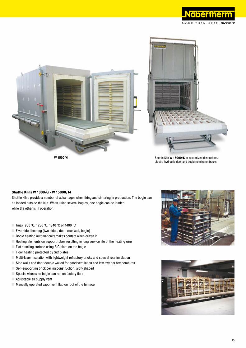
W 1500/H
Shuttle Kilns W 1000/G - W 15000/14Shuttle kilns provide a number of advantages when firing and sintering in production. The bogie can be loaded outside the kiln. When using several bogies, one bogie can be loaded while the other is in operation.
Tmax 900 °C, 1�80 °C, 1340 °C or 1400 °C Five-sided heating (two sides, door, rear wall, bogie) Bogie heating automatically makes contact when driven in Heating elements on support tubes resulting in long service life of the heating wire Flat stacking surface using SiC plate on the bogie Floor heating protected by SiC plates Multi-layer insulation with lightweight refractory bricks and special rear insulation Side walls and door double walled for good ventilation and low exterior temperatures Self-supporting brick ceiling construction, arch-shaped Special wheels so bogie can run on factory floor Adjustable air supply vent Manually operated vapor vent flap on roof of the furnace
Shuttle Kiln W 15000/S in customized dimensions,electro-hydraulic door and bogie running on tracks
15
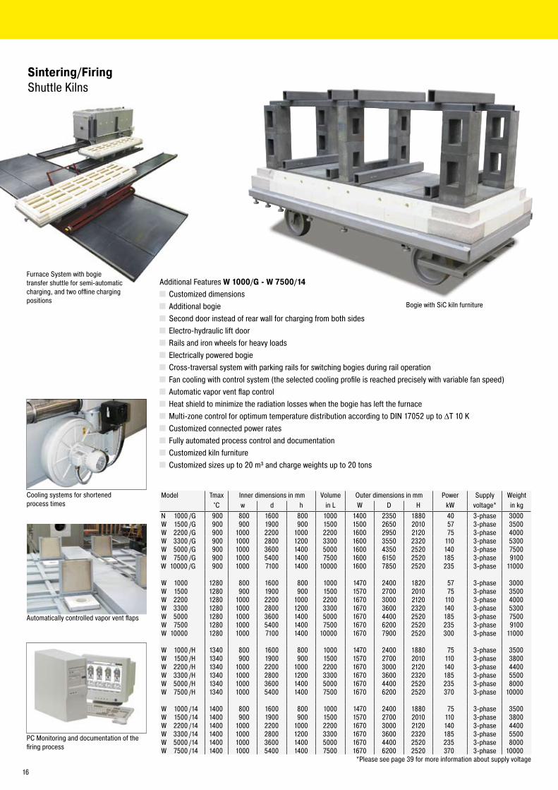
Additional Features W 1000/G - W 7500/14 Customized dimensions Additional bogie Second door instead of rear wall for charging from both sides Electro-hydraulic lift door Rails and iron wheels for heavy loads Electrically powered bogie Cross-traversal system with parking rails for switching bogies during rail operation Fan cooling with control system (the selected cooling profile is reached precisely with variable fan speed) Automatic vapor vent flap control Heat shield to minimize the radiation losses when the bogie has left the furnace Multi-zone control for optimum temperature distribution according to DIN 1705� up to ΔT 10 K Customized connected power rates Fully automated process control and documentation Customized kiln furniture Customized sizes up to �0 m³ and charge weights up to �0 tons
Bogie with SiC kiln furniture
Sintering/FiringShuttle Kilns
Cooling systems for shortened process times
Automatically controlled vapor vent flaps
PC Monitoring and documentation of the firing process
Model Tmax Inner dimensions in mm Volume Outer dimensions in mm Power Supply Weight°C w d h in L W D H kW voltage* in kg
N 1000 /G 900 800 1600 800 1000 1400 �350 1880 40 3-phase 3000W 1500 /G 900 900 1900 900 1500 1500 �650 �010 57 3-phase 3500W ��00 /G 900 1000 ��00 1000 ��00 1600 �950 �1�0 75 3-phase 4000W 3300 /G 900 1000 �800 1�00 3300 1600 3550 �3�0 110 3-phase 5300W 5000 /G 900 1000 3600 1400 5000 1600 4350 �5�0 140 3-phase 7500W 7500 /G 900 1000 5400 1400 7500 1600 6150 �5�0 185 3-phase 9100W 10000 /G 900 1000 7100 1400 10000 1600 7850 �5�0 �35 3-phase 11000
W 1000 1�80 800 1600 800 1000 1470 �400 18�0 57 3-phase 3000W 1500 1�80 900 1900 900 1500 1570 �700 �010 75 3-phase 3500W ��00 1�80 1000 ��00 1000 ��00 1670 3000 �1�0 110 3-phase 4000W 3300 1�80 1000 �800 1�00 3300 1670 3600 �3�0 140 3-phase 5300W 5000 1�80 1000 3600 1400 5000 1670 4400 �5�0 185 3-phase 7500W 7500 1�80 1000 5400 1400 7500 1670 6�00 �5�0 �35 3-phase 9100W 10000 1�80 1000 7100 1400 10000 1670 7900 �5�0 300 3-phase 11000
W 1000 /H 1340 800 1600 800 1000 1470 �400 1880 75 3-phase 3500W 1500 /H 1340 900 1900 900 1500 1570 �700 �010 110 3-phase 3800W ��00 /H 1340 1000 ��00 1000 ��00 1670 3000 �1�0 140 3-phase 4400W 3300 /H 1340 1000 �800 1�00 3300 1670 3600 �3�0 185 3-phase 5500W 5000 /H 1340 1000 3600 1400 5000 1670 4400 �5�0 �35 3-phase 8000W 7500 /H 1340 1000 5400 1400 7500 1670 6�00 �5�0 370 3-phase 10000
W 1000 /14 1400 800 1600 800 1000 1470 �400 1880 75 3-phase 3500W 1500 /14 1400 900 1900 900 1500 1570 �700 �010 110 3-phase 3800W ��00 /14 1400 1000 ��00 1000 ��00 1670 3000 �1�0 140 3-phase 4400W 3300 /14 1400 1000 �800 1�00 3300 1670 3600 �3�0 185 3-phase 5500W 5000 /14 1400 1000 3600 1400 5000 1670 4400 �5�0 �35 3-phase 8000W 7500 /14 1400 1000 5400 1400 7500 1670 6�00 �5�0 370 3-phase 10000
*Please see page 39 for more information about supply voltage
Furnace System with bogie transfer shuttle for semi-automatic charging, and two offline charging positions
16
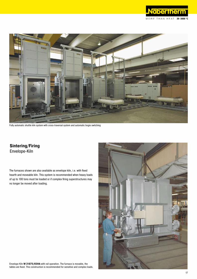
Fully automatic shuttle kiln system with cross-traversal system and automatic bogie switching
Sintering/FiringEnvelope-Kiln
Envelope Kiln W 21875/65HA with rail operation. The furnace is movable, the tables are fixed. This construction is recommended for sensitive and complex loads.
The furnaces shown are also available as envelope kiln, i.e. with fixed hearth and moveable kiln. This system is recommended when heavy loads of up to 100 tons must be loaded or if complex firing superstructures may no longer be moved after loading.
17
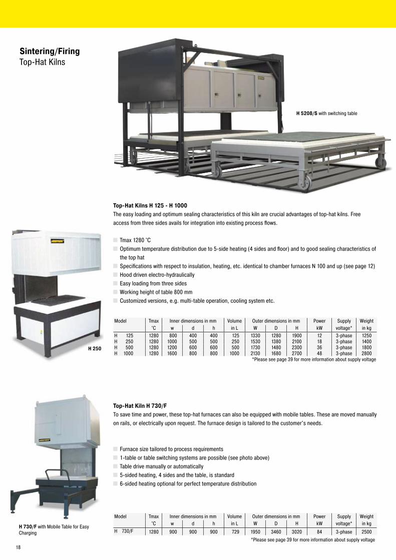
H 250
Top-Hat Kilns H 125 - H 1000The easy loading and optimum sealing characteristics of this kiln are crucial advantages of top-hat kilns. Free access from three sides avails for integration into existing process flows.
Tmax 1�80 °C Optimum temperature distribution due to 5-side heating (4 sides and floor) and to good sealing characteristics of the top hat
Specifications with respect to insulation, heating, etc. identical to chamber furnaces N 100 and up (see page 1�) Hood driven electro-hydraulically Easy loading from three sides Working height of table 800 mm Customized versions, e.g. multi-table operation, cooling system etc.
Sintering/FiringTop-Hat Kilns
H 5208/S with switching table
H 730/F with Mobile Table for Easy Charging
Model Tmax Inner dimensions in mm Volume Outer dimensions in mm Power Supply Weight°C w d h in L W D H kW voltage* in kg
H 1�5 1�80 800 400 400 1�5 1330 1�80 1900 1� 3-phase 1�50H �50 1�80 1000 500 500 �50 1530 1380 �100 18 3-phase 1400H 500 1�80 1�00 600 600 500 1730 1480 �300 36 3-phase 1800H 1000 1�80 1600 800 800 1000 �130 1680 �700 48 3-phase �800 *Please see page 39 for more information about supply voltage
Model Tmax Inner dimensions in mm Volume Outer dimensions in mm Power Supply Weight°C w d h in L W D H kW voltage* in kg
H 730/F 1�80 900 900 900 7�9 1950 3460 30�0 84 3-phase �500 *Please see page 39 for more information about supply voltage
Top-Hat Kiln H 730/FTo save time and power, these top-hat furnaces can also be equipped with mobile tables. These are moved manually on rails, or electrically upon request. The furnace design is tailored to the customer's needs.
Furnace size tailored to process requirements 1-table or table switching systems are possible (see photo above) Table drive manually or automatically 5-sided heating, 4 sides and the table, is standard 6-sided heating optional for perfect temperature distribution
18
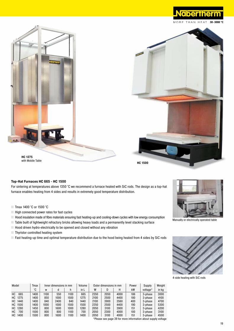
HC 1500
Top-Hat Furnaces HC 665 - HC 1500For sintering at temperatures above 1350 °C we recommend a furnace heated with SiC rods. The design as a top-hat furnace enables heating from 4 sides and results in extremely good temperature distribution.
Tmax 1400 °C or 1500 °C High connected power rates for fast cycles Hood insulation made of fibre materials ensuring fast heating-up and cooling-down cycles with low energy consumption Table built of lightweight refractory bricks allowing heavy loads and a permanently level stacking surface Hood driven hydro-electrically to be opened and closed without any vibration Thyristor controlled heating system Fast heating-up time and optimal temperature distribution due to the hood being heated from 4 sides by SiC rods
HC 1275 with Mobile Table
Manually or electrically operated table
4-side heating with SiC rods
Model Tmax Inner dimensions in mm Volume Outer dimensions in mm Power Supply Weight°C w d h in L W D H kW voltage* in kg
HC 665 1400 1100 550 1100 665 �350 �050 4000 186 3-phase 3000HC 1�75 1400 850 1000 1500 1�75 �100 �500 4400 180 3-phase 4100HC 1440 1400 840 �400 840 1440 �100 3900 3560 400 3-phase 4700HC 1500 1400 1000 1000 1500 1500 ��50 �500 4400 190 3-phase 5300HC 1�80 1450 800 1600 1000 1�80 �050 3100 3900 151 3-phase 4�00HC 700 1500 800 800 1100 700 �050 �300 4000 100 3-phase 3100HC 1400 1500 800 1600 1100 1400 �050 3100 4000 151 3-phase 4500 *Please see page 39 for more information about supply voltage
19
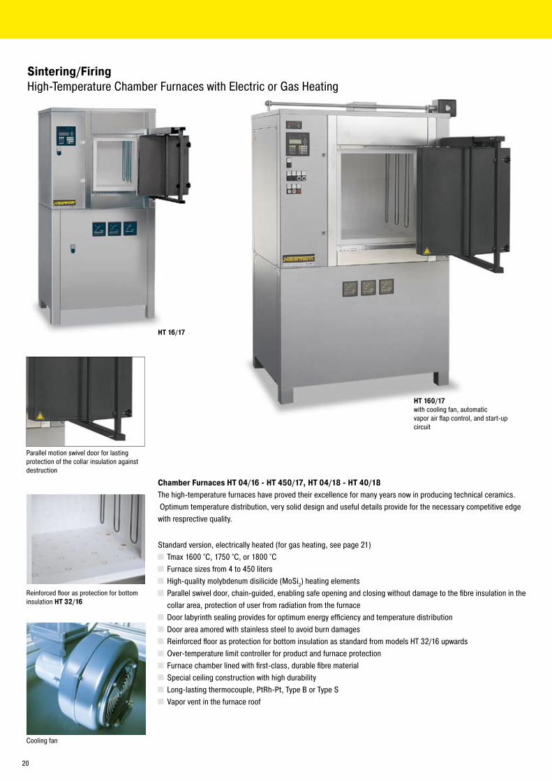
HT 16/17
HT 160/17 with cooling fan, automaticvapor air flap control, and start-up circuit
Chamber Furnaces HT 04/16 - HT 450/17, HT 04/18 - HT 40/18The high-temperature furnaces have proved their excellence for many years now in producing technical ceramics. Optimum temperature distribution, very solid design and useful details provide for the necessary competitive edge with resprective quality.
Standard version, electrically heated (for gas heating, see page �1) Tmax 1600 °C, 1750 °C, or 1800 °C Furnace sizes from 4 to 450 liters High-quality molybdenum disilicide (MoSi�) heating elements Parallel swivel door, chain-guided, enabling safe opening and closing without damage to the fibre insulation in the collar area, protection of user from radiation from the furnace
Door labyrinth sealing provides for optimum energy efficiency and temperature distribution Door area amored with stainless steel to avoid burn damages Reinforced floor as protection for bottom insulation as standard from models HT 3�/16 upwards Over-temperature limit controller for product and furnace protection Furnace chamber lined with first-class, durable fibre material Special ceiling construction with high durability Long-lasting thermocouple, PtRh-Pt, Type B or Type S Vapor vent in the furnace roof
Parallel motion swivel door for lasting protection of the collar insulation against destruction
Reinforced floor as protection for bottom insulation HT 32/16
Sintering/FiringHigh-Temperature Chamber Furnaces with Electric or Gas Heating
Cooling fan
�0
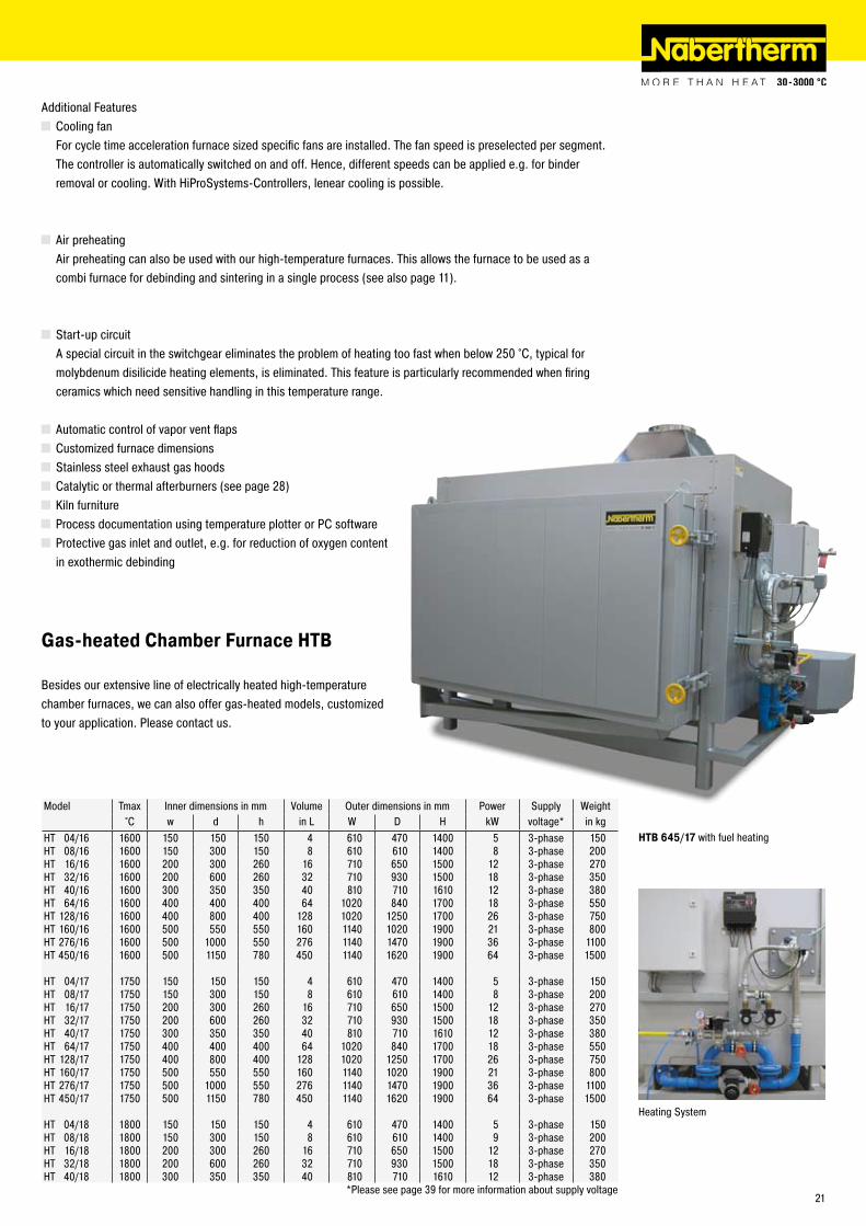
Additional Features Cooling fan For cycle time acceleration furnace sized specific fans are installed. The fan speed is preselected per segment. The controller is automatically switched on and off. Hence, different speeds can be applied e.g. for binder removal or cooling. With HiProSystems-Controllers, lenear cooling is possible.
Air preheating Air preheating can also be used with our high-temperature furnaces. This allows the furnace to be used as a combi furnace for debinding and sintering in a single process (see also page 11).
Start-up circuit A special circuit in the switchgear eliminates the problem of heating too fast when below �50 °C, typical for molybdenum disilicide heating elements, is eliminated. This feature is particularly recommended when firing ceramics which need sensitive handling in this temperature range.
Automatic control of vapor vent flaps Customized furnace dimensions Stainless steel exhaust gas hoods Catalytic or thermal afterburners (see page �8) Kiln furniture Process documentation using temperature plotter or PC software Protective gas inlet and outlet, e.g. for reduction of oxygen content in exothermic debinding
Gas-heated Chamber Furnace HTB
Besides our extensive line of electrically heated high-temperature chamber furnaces, we can also offer gas-heated models, customized to your application. Please contact us.
Model Tmax Inner dimensions in mm Volume Outer dimensions in mm Power Supply Weight°C w d h in L W D H kW voltage* in kg
HT 04/16 1600 150 150 150 4 610 470 1400 5 3-phase 150HT 08/16 1600 150 300 150 8 610 610 1400 8 3-phase �00HT 16/16 1600 �00 300 �60 16 710 650 1500 1� 3-phase �70HT 3�/16 1600 �00 600 �60 3� 710 930 1500 18 3-phase 350HT 40/16 1600 300 350 350 40 810 710 1610 1� 3-phase 380HT 64/16 1600 400 400 400 64 10�0 840 1700 18 3-phase 550HT 1�8/16 1600 400 800 400 1�8 10�0 1�50 1700 �6 3-phase 750HT 160/16 1600 500 550 550 160 1140 10�0 1900 �1 3-phase 800HT �76/16 1600 500 1000 550 �76 1140 1470 1900 36 3-phase 1100HT 450/16 1600 500 1150 780 450 1140 16�0 1900 64 3-phase 1500
HT 04/17 1750 150 150 150 4 610 470 1400 5 3-phase 150HT 08/17 1750 150 300 150 8 610 610 1400 8 3-phase �00HT 16/17 1750 �00 300 �60 16 710 650 1500 1� 3-phase �70HT 3�/17 1750 �00 600 �60 3� 710 930 1500 18 3-phase 350HT 40/17 1750 300 350 350 40 810 710 1610 1� 3-phase 380HT 64/17 1750 400 400 400 64 10�0 840 1700 18 3-phase 550HT 1�8/17 1750 400 800 400 1�8 10�0 1�50 1700 �6 3-phase 750HT 160/17 1750 500 550 550 160 1140 10�0 1900 �1 3-phase 800HT �76/17 1750 500 1000 550 �76 1140 1470 1900 36 3-phase 1100HT 450/17 1750 500 1150 780 450 1140 16�0 1900 64 3-phase 1500
HT 04/18 1800 150 150 150 4 610 470 1400 5 3-phase 150HT 08/18 1800 150 300 150 8 610 610 1400 9 3-phase �00HT 16/18 1800 �00 300 �60 16 710 650 1500 1� 3-phase �70HT 3�/18 1800 �00 600 �60 3� 710 930 1500 18 3-phase 350HT 40/18 1800 300 350 350 40 810 710 1610 1� 3-phase 380
*Please see page 39 for more information about supply voltage
HTB 645/17 with fuel heating
Heating System
�1

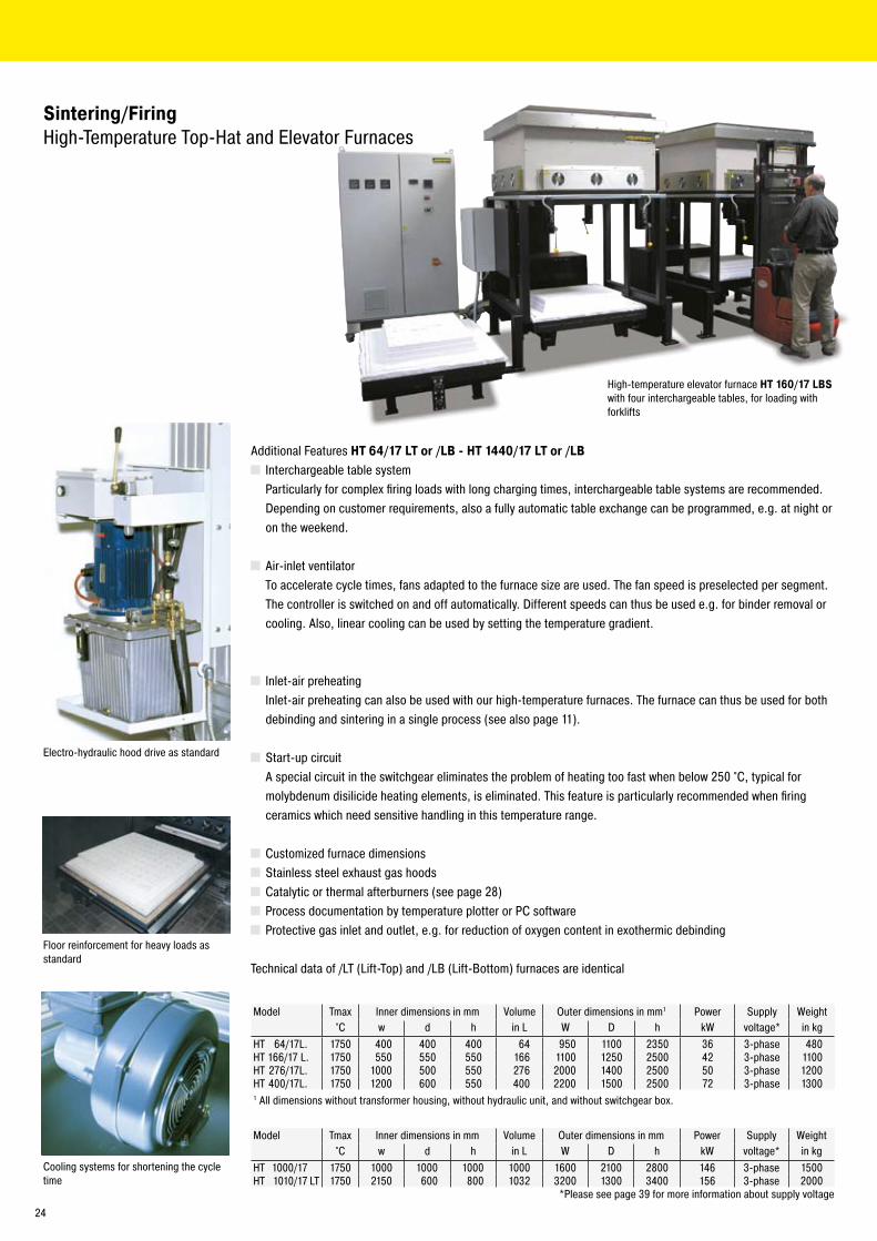
Sintering/FiringHigh-Temperature Top-Hat and Elevator Furnaces
High-temperature elevator furnaces HT 1440/17LBS with inlet air preheating for debinding and sintering
��
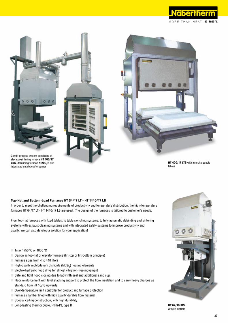
Top-Hat and Bottom-Load Furnaces HT 64/17 LT - HT 1440/17 LBIn order to meet the challenging requirements of productivity and temperature distribution, the high-temperature furnaces HT 64/17 LT - HT 1440/17 LB are used. The design of the furnaces is tailored to customer's needs.
From top-hat furnaces with fixed tables, to table switching systems, to fully automatic debinding and sintering systems with exhaust cleaning systems and with integrated safety systems to improve productivity and quality, we can also develop a solution for your application!
Tmax 1750 °C or 1800 °C Design as top-hat or elevator furnace (lift-top or lift-bottom principle) Furnace sizes from 4 to 440 liters High-quality molybdenum disilicide (MoSi�) heating elements Electro-hydraulic hood drive for almost vibration-free movement Safe and tight hood closing due to labyrinth seal and additional sand cup Floor reinforcement with level stacking support to protect the fibre insulation and to carry heavy charges as standard from HT 16/16 upwards
Over-temperature limit controller for product and furnace protection Furnace chamber lined with high quality durable fibre material Special ceiling construction, with high durability Long-lasting thermocouple, PtRh-Pt, type B
HT 400/17 LTS with interchargeable tables
Combi-process system consisting of elevator-sintering furnace HT 166/17 LBS, debinding furnace N 200/H and integrated catalytic afterburner
HT 64/16LBS with lift-bottom
�3
Model Tmax Inner dimensions in mm Volume Outer dimensions in mm1 Power Supply Weight°C w d h in L W D h kW voltage* in kg
HT 64/17L. 1750 400 400 400 64 950 1100 �350 36 3-phase 480HT 166/17 L. 1750 550 550 550 166 1100 1�50 �500 4� 3-phase 1100HT �76/17L. 1750 1000 500 550 �76 �000 1400 �500 50 3-phase 1�00HT 400/17L. 1750 1�00 600 550 400 ��00 1500 �500 7� 3-phase 13001 All dimensions without transformer housing, without hydraulic unit, and without switchgear box.
Model Tmax Inner dimensions in mm Volume Outer dimensions in mm Power Supply Weight°C w d h in L W D h kW voltage* in kg
HT 1000/17 1750 1000 1000 1000 1000 1600 �100 �800 146 3-phase 1500HT 1010/17 LT 1750 �150 600 800 103� 3�00 1300 3400 156 3-phase �000
*Please see page 39 for more information about supply voltage
Additional Features HT 64/17 LT or /LB - HT 1440/17 LT or /LB Interchargeable table system
Particularly for complex firing loads with long charging times, interchargeable table systems are recommended. Depending on customer requirements, also a fully automatic table exchange can be programmed, e.g. at night or on the weekend.
Air-inlet ventilator To accelerate cycle times, fans adapted to the furnace size are used. The fan speed is preselected per segment.
The controller is switched on and off automatically. Different speeds can thus be used e.g. for binder removal or cooling. Also, linear cooling can be used by setting the temperature gradient.
Inlet-air preheating Inlet-air preheating can also be used with our high-temperature furnaces. The furnace can thus be used for both
debinding and sintering in a single process (see also page 11).
Start-up circuit A special circuit in the switchgear eliminates the problem of heating too fast when below �50 °C, typical for
molybdenum disilicide heating elements, is eliminated. This feature is particularly recommended when firing ceramics which need sensitive handling in this temperature range.
Customized furnace dimensions Stainless steel exhaust gas hoods Catalytic or thermal afterburners (see page �8) Process documentation by temperature plotter or PC software Protective gas inlet and outlet, e.g. for reduction of oxygen content in exothermic debinding
Technical data of /LT (Lift-Top) and /LB (Lift-Bottom) furnaces are identical
Cooling systems for shortening the cycle time
Electro-hydraulic hood drive as standard
Floor reinforcement for heavy loads as standard
Sintering/FiringHigh-Temperature Top-Hat and Elevator Furnaces
High-temperature elevator furnace HT 160/17 LBSwith four interchargeable tables, for loading with forklifts
�4
HT 64/17LT
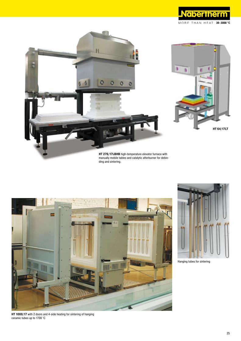
Hanging tubes for sintering
HT 1000/17 with � doors and 4-side heating for sintering of hanging ceramic tubes up to 1700 °C
HT 276/17LBHB high-temperature elevator furnace with manually mobile tables and catalytic afterburner for debin-ding and sintering.
�5
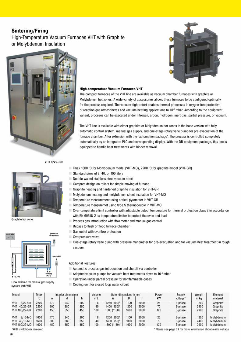
VHT 8/22-GR
Sintering/FiringHigh-Temperature Vacuum Furnaces VHT with Graphiteor Molybdenum Insulation
Model Tmax Interior dimensions Volume Outer dimensions in mm Power Supply Weight Element°C w d h in L W D H kW voltage* in kg material
VHT 8/��-GR ��00 170 �40 �00 8 1�50 (800)1 1100 �000 �5 3-phase 1�00 GraphiteVHT 40/��-GR ��00 300 380 350 40 1400 (950)1 1300 �000 70 3-phase �400 GraphiteVHT 100/��-GR ��00 450 550 450 100 1600 (1150)1 1600 �000 1�0 3-phase �900 Graphite
VHT 8/16-MO 1600 170 �40 �00 8 1�50 (800)1 1100 �000 �5 3-phase 1�00 MolybdenumVHT 40/16-MO 1600 300 380 350 40 1400 (950)1 1300 �000 70 3-phase �400 MolybdenumVHT 100/��-MO 1600 450 550 450 100 1600 (1150)1 1600 �000 1�0 3-phase �900 Molybdenum1With switchgear removed *Please see page 39 for more information about mains voltage
High-temperature Vacuum Furnaces VHTThe compact furnaces of the VHT line are available as vacuum chamber furnaces with graphite or Molybdenum hot zones. A wide variety of accessories allows these furnaces to be configured optimally for the process required. The vacuum-tight retort enables thermal processes in oxygen-free protective or reaction gas atmospheres and vacuum heating applications to 10-5 mbar. According to the equipment variant, proceses can be executed under nitrogen, argon, hydrogen, inert gas, partial pressure, or vacuum.
The VHT line is available with either graphite or Molybdenum hot zones in the base version with fully automatic control system, manual gas supply, and one-stage rotary vane pump for pre-evacuation of the furnace chamber. After extension with the "automation package", the process is controlled completely automatically by an integrated PLC and corresponding display. With the DB equipment package, this line is equipped to handle heat treatments with binder removal.
Tmax 1600 °C for Molybdenum model (VHT-MO), ��00 °C for graphite model (VHT-GR) Standard sizes of 8, 40, or 100 liters Double-walled stainless steel vacuum retort Compact design on rollers for simple moving of furnace Graphite heating and hardened graphite insulation for VHT-GR Molybdenum heating and molybdenum sheet insulation for VHT-MO Temperature measurement using optical pyrometer in VHT-GR Temperature measuremet using type S thermocouple in VHT-MO Over-temperature limit controller with adjustable cutout temperature for thermal protection class � in accordance with EN 60518-� as temperature limiter to protect the oven and load
Process gas introduction with flow meter and manual gas control Bypass to flush or flood furnace chamber Gas outlet with overflow protection Overpressure valve One-stage rotary vane pump with pressure manometer for pre-evacuation and for vacuum heat treatment in rough vacuum
Additional Features Automatic process gas introduction and shutoff via controller Adapted vacuum pumps for vacuum heat treatments down to 10-5 mbar Operation under partial pressure for nonflammable gases Cooling unit for closed loop water circuit
Flow scheme for manual gas supply system with VHT
Graphite hot zone
�6
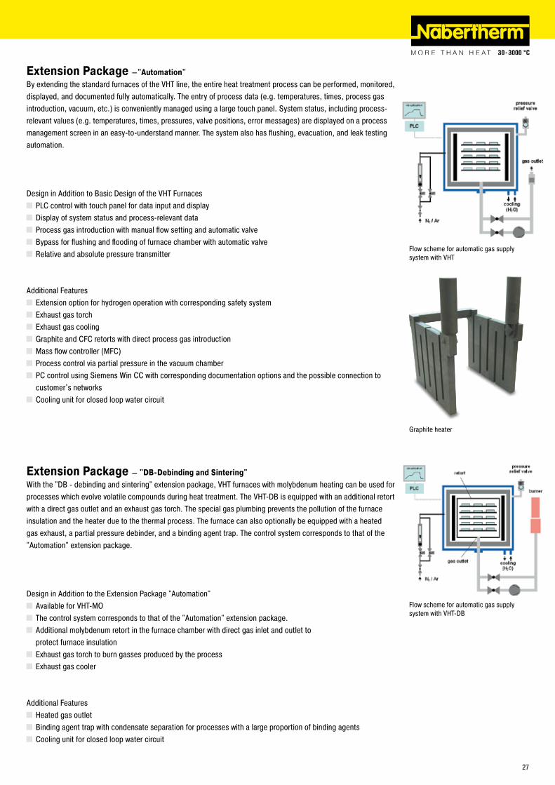
Graphite heater
Extension Package –"Automation"By extending the standard furnaces of the VHT line, the entire heat treatment process can be performed, monitored, displayed, and documented fully automatically. The entry of process data (e.g. temperatures, times, process gas introduction, vacuum, etc.) is conveniently managed using a large touch panel. System status, including process-relevant values (e.g. temperatures, times, pressures, valve positions, error messages) are displayed on a process management screen in an easy-to-understand manner. The system also has flushing, evacuation, and leak testing automation.
Design in Addition to Basic Design of the VHT Furnaces PLC control with touch panel for data input and display Display of system status and process-relevant data Process gas introduction with manual flow setting and automatic valve Bypass for flushing and flooding of furnace chamber with automatic valve Relative and absolute pressure transmitter
Additional Features Extension option for hydrogen operation with corresponding safety system Exhaust gas torch Exhaust gas cooling Graphite and CFC retorts with direct process gas introduction Mass flow controller (MFC) Process control via partial pressure in the vacuum chamber PC control using Siemens Win CC with corresponding documentation options and the possible connection to customer's networks
Cooling unit for closed loop water circuit
Extension Package – "DB-Debinding and Sintering"With the "DB - debinding and sintering" extension package, VHT furnaces with molybdenum heating can be used for processes which evolve volatile compounds during heat treatment. The VHT-DB is equipped with an additional retort with a direct gas outlet and an exhaust gas torch. The special gas plumbing prevents the pollution of the furnace insulation and the heater due to the thermal process. The furnace can also optionally be equipped with a heated gas exhaust, a partial pressure debinder, and a binding agent trap. The control system corresponds to that of the "Automation" extension package.
Design in Addition to the Extension Package "Automation" Available for VHT-MO The control system corresponds to that of the "Automation" extension package. Additional molybdenum retort in the furnace chamber with direct gas inlet and outlet to
protect furnace insulation Exhaust gas torch to burn gasses produced by the process Exhaust gas cooler
Additional Features Heated gas outlet Binding agent trap with condensate separation for processes with a large proportion of binding agents Cooling unit for closed loop water circuit
Flow scheme for automatic gas supply system with VHT
Flow scheme for automatic gas supply system with VHT-DB
�7
Debinding and sintering plant with catalytic afterburning system
Catalytic and Thermal Afterburning SystemsFor exhaust air cleaning, especially during debinding, Nabertherm offers afterburning systems tailored to the process. Catalytic systems for cracking organic compounds can be provided as well as thermal systems for higher exhaust volumes or anorganic waste gases.
Catalytic or thermal afterburners Customized size and design tailored to process conditions Catalytic afterburner including electrical heater for heating up the exhaust air to the reaction temperature Sophisticated safety concepts for complex plants (e.g.protection against restarting if process is interrupted in critical segments, flooding the furnace chamber with nitrogen or air before restarting etc.)
Debinding and Sintering Systems with Catalytic or Thermal Afterburners
Gas-supply panel
PC process visualization
�8
Bogie hearth furnace plant with integrated thermal afterburner
In addition to supplying a furnace, Nabertherm offers process and production technology solutions to improve your productivity and/or production capacity. Our experienced engineers can provide support for:
Planning and designing furnace and exhaust systems Assembly and commissioning of the entire plant including construction of ductwork Accompanying emission measurements required by public institutions Material flow solutions for integrating upstream and downstream process steps Detailed visualization of process monitoring and documentation to provide for quality relevant production data
Plant Concepts
Top-hat system for sintering of technical ceramics with two cooling stations for fully automatic operation
Fully automatic production system consisting of 8 air circulating bogie-hearth furnaces, two cooling stations, and loading/unloading area
Unlo
adin
gLo
adin
g
Furnace 1 Furnace 4
Furnace 8 Cooling station
Furnace � Furnace 3
Furnace 7 Furnace 6 Furnace 5
Cooling station
�9
Interior of low heat storage fibre material for fast cooling times in LF models
Cooling fan connected to automatic vent flap for shorter cooling time
LH 60/12 with brick insulation
LH 15/12 with brick insulation
LaboratoryProfessional Chamber Furnaces with Brick Insulation LH or Fibre Insulation LF
Laboratory-Chamber Furnaces LH 15/12 - LF 120/14The LH 15/1� - LF 1�0/14 laboratory furnaces have been trusted for many years as professional chamber furnaces for the laboratory. These furnaces are available with either a robust insulation of light refractory bricks (LH models) or with a combination insulation of refractory bricks in the corners and low heat storage, quickly cooling fibre material (LF models). With a wide variety of optional equipment, these models can be optimally adapted to your processes.
Tmax 1�00 °C, 1300 °C, or 1400 °C 5-sided heating for very good temperature uniformity Heating elements on support tubes ensure free heat radiation and a long service life Protection of floor heating and flat stacking surface provided by embedded SiC plate in the floor LH models: multilayered, fibre-free insulation of light refractory bricks and special backup insulation LF models: high-quality fibre insulation with corner bricks for shorter heating and cooling times Door with brick-on-brick seal, hand fitted Short heating times due to high installed power Side vent with bypass connection for exhaust pipe Self-supporting arch for high stability and greatest possible protection against dust Quick lock on door Freely adjustable air slide intake in furnace floor Stand included
30
Parallel swinging door for opening whenhot
LF 120/12 with fibre insulation
Additional Features Parallel swinging door, pivots away from operator, for opening when hot Separate wall-mounting or floor standing cabinet for switchgear Automatic vent flap Cooling fan for shorter cycle times Protective gas connector, sealed casing Manual or automatic gas supply system
Gas panel
LH 120/12S with gas supply system and sight port in the door
Model Tmax Inner dimensions in mm Volume Outer dimensions in mm Power Supply Weight°C w d h in L W D H kW voltage* in kg
LH 15/1� 1�00 �50 �50 �50 15 570 790 1170 5,0 3-phase1 150LH 30/1� 1�00 3�0 3�0 3�0 30 640 860 1�40 7,0 3-phase1 170LH 60/1� 1�00 400 400 400 60 7�0 1010 13�0 8,0 3-phase �60LH 1�0/1� 1�00 500 500 500 1�0 8�0 1110 14�0 1�,0 3-phase 340
LH 15/13 1300 �50 �50 �50 15 570 790 1170 7,0 3-phase1 150LH 30/13 1300 3�0 3�0 3�0 30 640 860 1�40 8,0 3-phase1 170LH 60/13 1300 400 400 400 60 7�0 1010 13�0 11,0 3-phase �60LH 1�0/13 1300 500 500 500 1�0 8�0 1110 14�0 15,0 3-phase 340
LH 15/14 1400 �50 �50 �50 15 570 790 1170 8,0 3-phase1 150LH 30/14 1400 3�0 3�0 3�0 30 640 860 1�40 10,0 3-phase1 170LH 60/14 1400 400 400 400 60 7�0 1010 13�0 1�,0 3-phase �60LH 1�0/14 1400 500 500 500 1�0 8�0 1110 14�0 18,0 3-phase 340
Model Tmax Inner dimensions in mm Volume Outer dimensions in mm Power Supply Weight°C w d h in L W D H kW voltage* in kg
LF 15/13 1300 �50 �50 �50 15 570 790 1170 7,0 3-phase1 130LF 30/13 1300 3�0 3�0 3�0 30 640 860 1�40 8,0 3-phase1 150LF 60/13 1300 400 400 400 60 7�0 1010 13�0 11,0 3-phase �30LF 1�0/13 1300 500 500 500 1�0 8�0 1110 14�0 15,0 3-phase 300
LF 15/14 1400 �50 �50 �50 15 570 790 1170 8,0 3-phase1 130LF 30/14 1400 3�0 3�0 3�0 30 640 860 1�40 10,0 3-phase1 150LF 60/14 1400 400 400 400 60 7�0 1010 13�0 1�,0 3-phase �30LF 1�0/14 1400 500 500 500 1�0 8�0 1110 14�0 18,0 3-phase 300
1Heating only between two phases * Please see page 39 for more information about supply voltage
31
LS 12/13
LS 25/13
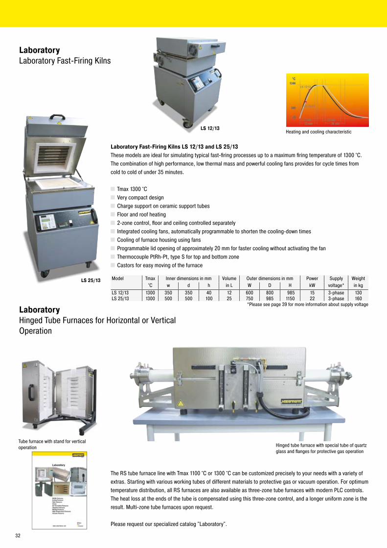
LaboratoryLaboratory Fast-Firing Kilns
Laboratory Fast-Firing Kilns LS 12/13 and LS 25/13These models are ideal for simulating typical fast-firing processes up to a maximum firing temperature of 1300 °C. The combination of high performance, low thermal mass and powerful cooling fans provides for cycle times from cold to cold of under 35 minutes.
Tmax 1300 °C Very compact design Charge support on ceramic support tubes Floor and roof heating �-zone control, floor and ceiling controlled separately Integrated cooling fans, automatically programmable to shorten the cooling-down times Cooling of furnace housing using fans Programmable lid opening of approximately �0 mm for faster cooling without activating the fan Thermocouple PtRh-Pt, type S for top and bottom zone Castors for easy moving of the furnace
Heating and cooling characteristic
LaboratoryHinged Tube Furnaces for Horizontal or Vertical Operation
Tube furnace with stand for vertical operation
Model Tmax Inner dimensions in mm Volume Outer dimensions in mm Power Supply Weight°C w d h in L W D H kW voltage* in kg
LS 1�/13 1300 350 350 40 1� 600 800 985 15 3-phase 130LS �5/13 1300 500 500 100 �5 750 985 1150 �� 3-phase 160
*Please see page 39 for more information about supply voltage
The RS tube furnace line with Tmax 1100 °C or 1300 °C can be customized precisely to your needs with a variety of extras. Starting with various working tubes of different materials to protective gas or vacuum operation. For optimum temperature distribution, all RS furnaces are also available as three-zone tube furnaces with modern PLC controls. The heat loss at the ends of the tube is compensated using this three-zone control, and a longer uniform zone is the result. Multi-zone tube furnaces upon request.
Please request our specialized catalog "Laboratory".
Hinged tube furnace with special tube of quartz glass and flanges for protective gas operation
3�
HTC 08/15
LHT 04/17
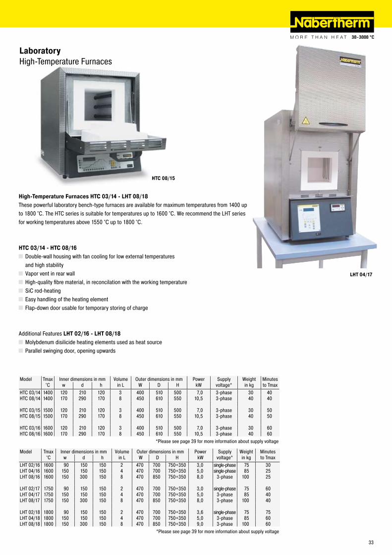
High-Temperature Furnaces HTC 03/14 - LHT 08/18These powerful laboratory bench-type furnaces are available for maximum temperatures from 1400 up to 1800 °C. The HTC series is suitable for temperatures up to 1600 °C. We recommend the LHT series for working temperatures above 1550 °C up to 1800 °C.
HTC 03/14 - HTC 08/16 Double-wall housing with fan cooling for low external temperatures
and high stability Vapor vent in rear wall High-quality fibre material, in reconcilation with the working temperature SiC rod-heating Easy handling of the heating element Flap-down door usable for temporary storing of charge
Additional Features LHT 02/16 - LHT 08/18 Molybdenum disilicide heating elements used as heat source Parallel swinging door, opening upwards
LaboratoryHigh-Temperature Furnaces
Model Tmax Inner dimensions in mm Volume Outer dimensions in mm Power Supply Weight Minutes°C w d h in L W D H kW voltage* in kg to Tmax
LHT 0�/16 1600 90 150 150 � 470 700 750+350 3,0 single-phase 75 30LHT 04/16 1600 150 150 150 4 470 700 750+350 5,0 single-phase 85 �5LHT 08/16 1600 150 300 150 8 470 850 750+350 8,0 3-phase 100 �5
LHT 0�/17 1750 90 150 150 � 470 700 750+350 3,0 single-phase 75 60LHT 04/17 1750 150 150 150 4 470 700 750+350 5,0 3-phase 85 40LHT 08/17 1750 150 300 150 8 470 850 750+350 8,0 3-phase 100 40
LHT 0�/18 1800 90 150 150 � 470 700 750+350 3,6 single-phase 75 75LHT 04/18 1800 150 150 150 4 470 700 750+350 5,0 3-phase 85 60LHT 08/18 1800 150 300 150 8 470 850 750+350 9,0 3-phase 100 60
*Please see page 39 for more information about supply voltage
Model Tmax Inner dimensions in mm Volume Outer dimensions in mm Power Supply Weight Minutes°C w d h in L W D H kW voltage* in kg to Tmax
HTC 03/14 1400 1�0 �10 1�0 3 400 510 500 7,0 3-phase 30 40HTC 08/14 1400 170 �90 170 8 450 610 550 10,5 3-phase 40 40
HTC 03/15 1500 1�0 �10 1�0 3 400 510 500 7,0 3-phase 30 50HTC 08/15 1500 170 �90 170 8 450 610 550 10,5 3-phase 40 50
HTC 03/16 1600 1�0 �10 1�0 3 400 510 500 7,0 3-phase 30 60HTC 08/16 1600 170 �90 170 8 450 610 550 10,5 3-phase 40 60
*Please see page 39 for more information about supply voltage
33
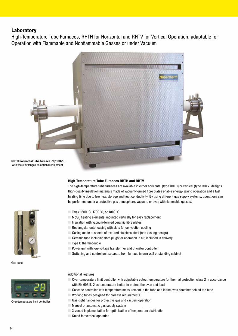
LaboratoryHigh-Temperature Tube Furnaces, RHTH for Horizontal and RHTV for Vertical Operation, adaptable for Operation with Flammable and Nonflammable Gasses or under Vacuum
High-Temperature Tube Furnaces RHTH and RHTVThe high-temperature tube furnaces are available in either horizontal (type RHTH) or vertical (type RHTV) designs. High-quality insulation materials made of vacuum-formed fibre plates enable energy-saving operation and a fast heating time due to low heat storage and heat conductivity. By using different gas supply systems, operations can be performed under a protective gas atmosphere, vacuum, or even with flammable gasses.
Tmax 1600 °C, 1700 °C, or 1800 °C MoSi� heating elements, mounted vertically for easy replacement Insulation with vacuum-formed ceramic fibre plates Rectangular outer casing with slots for convection cooling Casing made of sheets of textured stainless steel (non-rusting design) Ceramic tube including fibre plugs for operation in air, included in delivery Type B thermocouple Power unit with low-voltage transformer and thyristor controller Switching and control unit separate from furnace in own wall or standing cabinet
Additional Features Over-temperature limit controller with adjustable cutout temperature for thermal protection class � in accordance with EN 60518-� as temperature limiter to protect the oven and load
Cascade controller with temperature measurement in the tube and in the oven chamber behind the tube Working tubes designed for process requirements Gas-tight flanges for protective gas and vacuum operation Manual or automatic gas supply system 3-zoned implementation for optimization of temperature distribution Stand for vertical operation
RHTH horizontal tube furnace 70/300/16 with vacuum flanges as optional equipment
Over-temperature limit controller
Gas panel
34
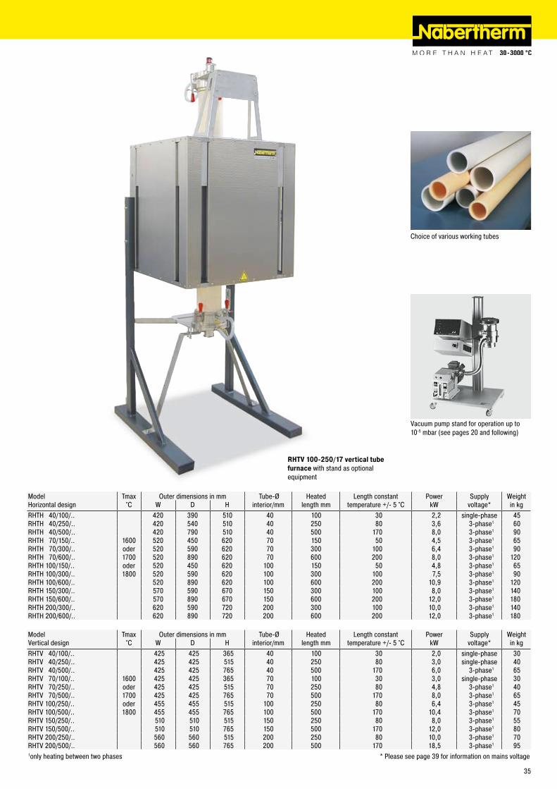
RHTV 100-250/17 vertical tube furnace with stand as optional equipment
Model Tmax Outer dimensions in mm Tube-Ø Heated Length constant Power Supply WeightHorizontal design °C W D H interior/mm length mm temperature +/- 5 °C kW voltage* in kgRHTH 40/100/.. 4�0 390 510 40 100 30 �,� single-phase 45RHTH 40/�50/.. 4�0 540 510 40 �50 80 3,6 3-phase1 60RHTH 40/500/.. 4�0 790 510 40 500 170 8,0 3-phase1 90RHTH 70/150/.. 1600 5�0 450 6�0 70 150 50 4,5 3-phase1 65RHTH 70/300/.. oder 5�0 590 6�0 70 300 100 6,4 3-phase1 90RHTH 70/600/.. 1700 5�0 890 6�0 70 600 �00 8,0 3-phase1 1�0RHTH 100/150/.. oder 5�0 450 6�0 100 150 50 4,8 3-phase1 65RHTH 100/300/.. 1800 5�0 590 6�0 100 300 100 7,5 3-phase1 90RHTH 100/600/.. 5�0 890 6�0 100 600 �00 10,9 3-phase1 1�0RHTH 150/300/.. 570 590 670 150 300 100 8,0 3-phase1 140RHTH 150/600/.. 570 890 670 150 600 �00 1�,0 3-phase1 180RHTH �00/300/.. 6�0 590 7�0 �00 300 100 10,0 3-phase1 140RHTH �00/600/.. 6�0 890 7�0 �00 600 �00 1�,0 3-phase1 180
Model Tmax Outer dimensions in mm Tube-Ø Heated Length constant Power Supply WeightVertical design °C W D H interior/mm length mm temperature +/- 5 °C kW voltage* in kgRHTV 40/100/.. 4�5 4�5 365 40 100 30 �,0 single-phase 30RHTV 40/�50/.. 4�5 4�5 515 40 �50 80 3,0 single-phase 40RHTV 40/500/.. 4�5 4�5 765 40 500 170 6,0 3-phase1 65RHTV 70/100/.. 1600 4�5 4�5 365 70 100 30 3,0 single-phase 30RHTV 70/�50/.. oder 4�5 4�5 515 70 �50 80 4,8 3-phase1 40RHTV 70/500/.. 1700 4�5 4�5 765 70 500 170 8,0 3-phase1 65RHTV 100/�50/.. oder 455 455 515 100 �50 80 6,4 3-phase1 45RHTV 100/500/.. 1800 455 455 765 100 500 170 10,4 3-phase1 70RHTV 150/�50/.. 510 510 515 150 �50 80 8,0 3-phase1 55RHTV 150/500/.. 510 510 765 150 500 170 1�,0 3-phase1 80RHTV �00/�50/.. 560 560 515 �00 �50 80 10,0 3-phase1 70RHTV �00/500/.. 560 560 765 �00 500 170 18,5 3-phase1 951only heating between two phases * Please see page 39 for information on mains voltage
Vacuum pump stand for operation up to 10-5 mbar (see pages �0 and following)
Choice of various working tubes
35
LaboratoryGas Supply Systems for Tube Furnaces RS, RHTH and RHTV
When equipped with various equipment packages, the tube furnace series RS, RHTH, and RHTV can be adapted for operation with nonflammable or flammable gasses or for vacuum operation. The different equipment packages can be delivered together with the furnace, or later as needed.
Gas Supply System 1 for simple protective gas applicationsThis package represents a basic version sufficient for many applications, for operation with nonflammable protective gasses. The standard working tube made of ceramic C 530 delivered with the furnace can still be used.
Tube of ceramic C 530 can be used � plugs of ceramic fibre with protective gas connections Gas supply system for nonflammable protective gas (Ar, N�, inert gas) with shutoff valve and flow meter with control valve (volume 50-500 l/hr), piped and ready to connect (gas intake pressure at 300 mbar to be provided by customer)
Additional Features Extension of gas supply system with a second or third nonflammable type of gas Bottle pressure regulator for use with bottled gas Automatically controlled gas supply with solenoid valves on the gas supply panel, which can be switched on and off through a controller with programmable extra functions (e.g. P 3�0)
Gas Supply System 2 for gas-tight operation with nonflammable gassesFor increased atmospheric purity requirements in the tube, we recommend this gas supply system. The standard working tube is replaced by a dense tube of ceramic C 610 or C 799 in a gas-tight design. Besides the longer working tube, the scope of delivery also includes gas-tight flanges and a corresponding bracket system in the furnace. The system can also be equipped for vacuum operation.
Longer, gas-tight working tube of ceramic C 610 for furnaces to 1300 °C or of C 799 for temperatures above 1300 °C
� vacuum-tight, water-cooled stainless steel flanges with fittings on the outlet side (cooling water supply with NW9 hose connector to be provided by the customer)
Mounting system on furnace for the flanges Gas supply system for nonflammable protective gas (Ar, N�, inert gas) with shutoff valve and flow meter with control valve (volume 50-500 l/hr), piped and ready to connect (gas intake pressure at 300 mbar to be provided by customer)
Additional Features Extension of gas supply system with a second or third nonflammable type of gas Bottle pressure regulator for use with bottled gas Automatically controlled gas supply with solenoid valves on the gas supply panel, which can be switched on and off through a controller with programmable extra functions (e.g. P 3�0)
Water-cooled end flange with quick connectors Vacuum package for evacuation of the working tube, consisting of a tee for the gas outlet, � ball valves, manometer, 1-stage manually operated rotary vane vacuum pump with corrugated stainless steel hose connected to the gas outlet, max. attainable end pressure in tube about 10-3 mbar
Vacuum package with adapted pumps for a max. end pressure down to 10-5 mbar upon request Cooling unit for closed loop water circuit
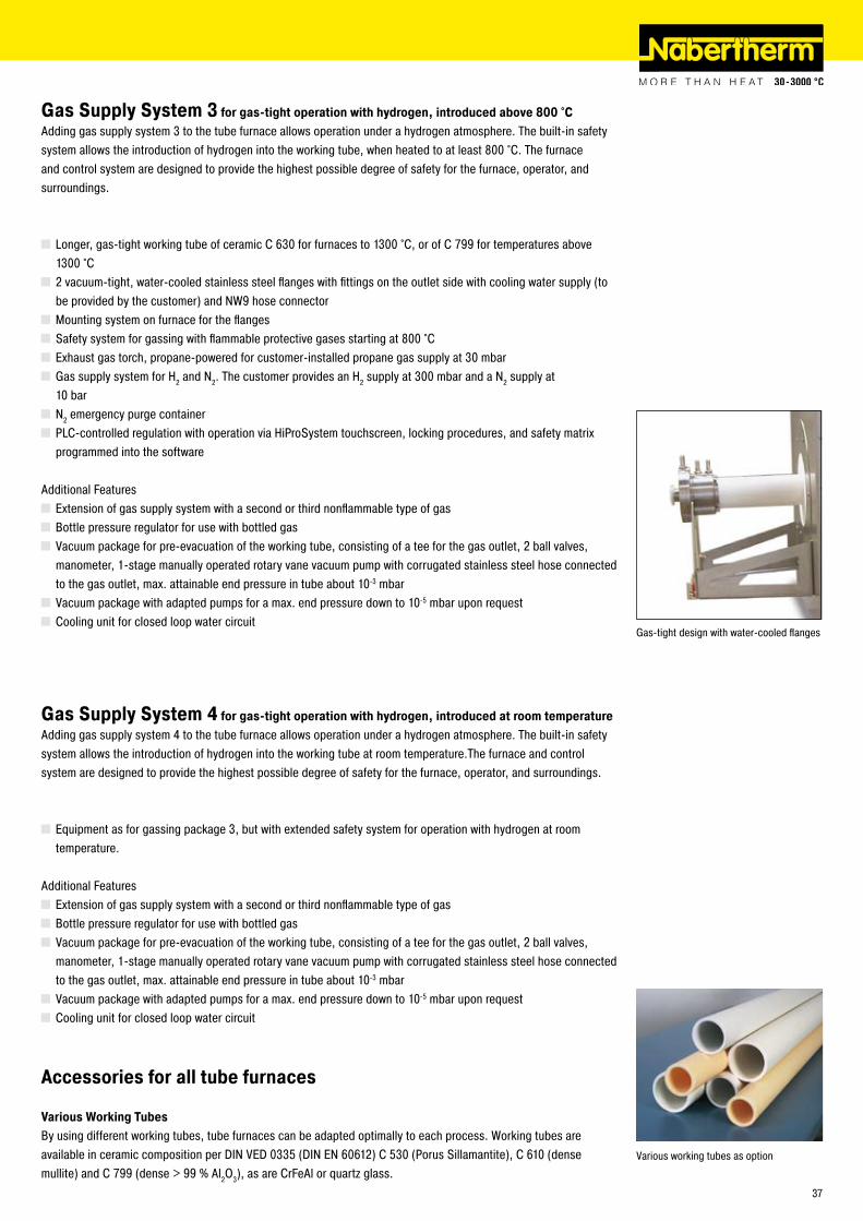
Gas supply panel for nonflammable protective gas with shutoff valve and flow meter with regulator valve, piped and ready to connect
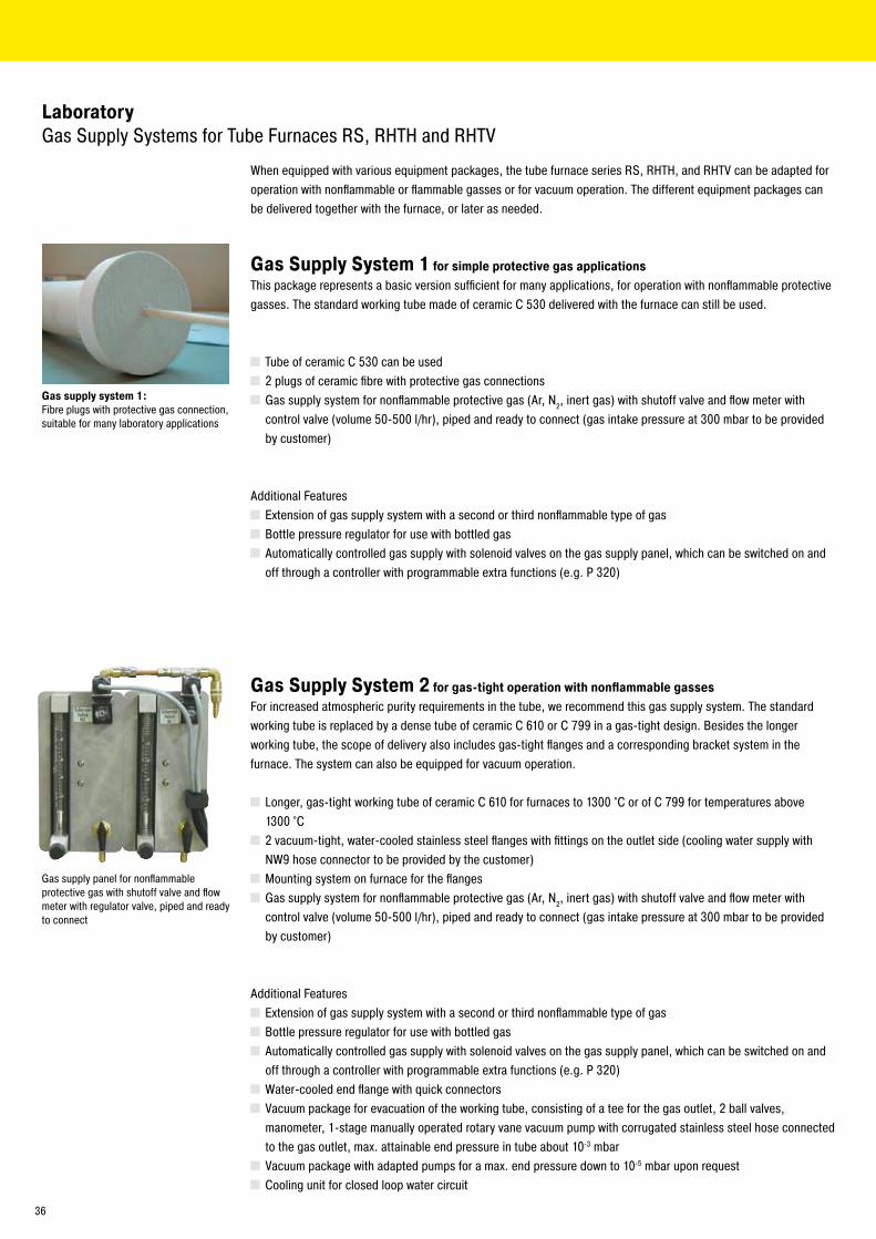
Gas supply system 1: Fibre plugs with protective gas connection, suitable for many laboratory applications
36
Gas Supply System 3 for gas-tight operation with hydrogen, introduced above 800 °CAdding gas supply system 3 to the tube furnace allows operation under a hydrogen atmosphere. The built-in safety system allows the introduction of hydrogen into the working tube, when heated to at least 800 °C. The furnace and control system are designed to provide the highest possible degree of safety for the furnace, operator, and surroundings.
Longer, gas-tight working tube of ceramic C 630 for furnaces to 1300 °C, or of C 799 for temperatures above 1300 °C
� vacuum-tight, water-cooled stainless steel flanges with fittings on the outlet side with cooling water supply (to be provided by the customer) and NW9 hose connector
Mounting system on furnace for the flanges Safety system for gassing with flammable protective gases starting at 800 °C Exhaust gas torch, propane-powered for customer-installed propane gas supply at 30 mbar Gas supply system for H� and N�. The customer provides an H� supply at 300 mbar and a N� supply at
10 bar N� emergency purge container PLC-controlled regulation with operation via HiProSystem touchscreen, locking procedures, and safety matrix programmed into the software
Additional Features Extension of gas supply system with a second or third nonflammable type of gas Bottle pressure regulator for use with bottled gas Vacuum package for pre-evacuation of the working tube, consisting of a tee for the gas outlet, � ball valves, manometer, 1-stage manually operated rotary vane vacuum pump with corrugated stainless steel hose connected to the gas outlet, max. attainable end pressure in tube about 10-3 mbar
Vacuum package with adapted pumps for a max. end pressure down to 10-5 mbar upon request Cooling unit for closed loop water circuit
Gas Supply System 4 for gas-tight operation with hydrogen, introduced at room temperatureAdding gas supply system 4 to the tube furnace allows operation under a hydrogen atmosphere. The built-in safety system allows the introduction of hydrogen into the working tube at room temperature.The furnace and control system are designed to provide the highest possible degree of safety for the furnace, operator, and surroundings.
Equipment as for gassing package 3, but with extended safety system for operation with hydrogen at room temperature.
Additional Features Extension of gas supply system with a second or third nonflammable type of gas Bottle pressure regulator for use with bottled gas Vacuum package for pre-evacuation of the working tube, consisting of a tee for the gas outlet, � ball valves, manometer, 1-stage manually operated rotary vane vacuum pump with corrugated stainless steel hose connected to the gas outlet, max. attainable end pressure in tube about 10-3 mbar
Vacuum package with adapted pumps for a max. end pressure down to 10-5 mbar upon request Cooling unit for closed loop water circuit
Accessories for all tube furnaces
Various Working TubesBy using different working tubes, tube furnaces can be adapted optimally to each process. Working tubes are available in ceramic composition per DIN VED 0335 (DIN EN 6061�) C 530 (Porus Sillamantite), C 610 (dense mullite) and C 799 (dense > 99 % Al�O3), as are CrFeAl or quartz glass.
Various working tubes as option
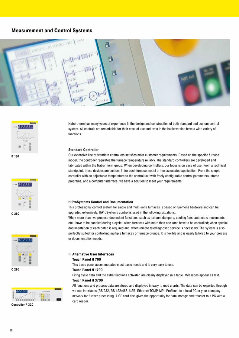
Gas-tight design with water-cooled flanges
37
B 130
C 280
C 295
Controller P 320
Measurement and Control Systems
Nabertherm has many years of experience in the design and construction of both standard and custom control system. All controls are remarkable for their ease of use and even in the basic version have a wide variety of functions.
Standard ControllerOur extensive line of standard controllers satisfies most customer requirements. Based on the specific furnace model, the controller regulates the furnace temperature reliably. The standard controllers are developed and fabricated within the Nabertherm group. When developing controllers, our focus is on ease of use. From a technical standpoint, these devices are custom-fit for each furnace model or the associated application. From the simple controller with an adjustable temperature to the control unit with freely configurable control parameters, stored programs, and a computer interface, we have a solution to meet your requirements.
HiProSystems Control and Documentation This professional control system for single and multi-zone furnaces is based on Siemens hardware and can be upgraded extensively. HiProSystems control is used in the following situations:When more than two process-dependent functions, such as exhaust dampers, cooling fans, automatic movements, etc., have to be handled during a cycle; when furnaces with more than one zone have to be controlled; when special documentation of each batch is required and; when remote telediagnostic service is necessary. The system is also perfectly suited for controlling multiple furnaces or furnace groups. It is flexible and is easily tailored to your process or documentation needs.
Alternative User Interfaces Touch Panel H 700 This basic panel accommodates most basic needs and is very easy to use. Touch Panel H 1700 Firing cycle data and the extra functions activated are clearly displayed in a table. Messages appear as text. Touch Panel H 3700 All functions and process data are stored and displayed in easy to read charts. The data can be exported through
various interfaces (RS �3�, RS 4��/485, USB, Ethernet TCI/IP, MPI, Profibus) to a local PC or your company network for further processing. A CF card also gives the opportunity for data storage and transfer to a PC with a card reader.
38
Mains Voltages for Nabertherm FurnacesSingle-phase: all furnaces are available for mains voltages from 110 V - �40 V at 50 or 60 Hz.Three-phase: all furnaces are available for mains voltages from �00 V - �40 V or 380 V - 480 V, at 50 or 60 Hz.
Nabertherm Control Center NCC (PC-based)Upgrading the HiProSystems-Control into an NCC provides for additional interfaces, operating documentation, and service benefits in particular for controlling furnace groups including charge beyond the furnace itself (quenching tank, cooling station etc.): Charge data can be read in via barcodes Interface for connection to existing Enterprise Database systems (e.g. SAP, Oracle) Internet connection for remote operation and monitoring Connection to mobile phone network for alarm message transmission via SMS Control from various locations over the network Documentation according to ISO 9000, etc. Maximum operator convenience: full keyboard, large screen Ideal for controlling furnace groups and documentation
Controltherm MV Software for Monitoring, Documentation and Control with Standard ControllersDocumentation and reproducibility are more important with the quality standards certain industries demand. Here, the powerful Nabertherm software, Controltherm MV provides an optimum solution for the control and documentation of one or more furnaces (furnace data only).
Features Parallel control/monitoring and documentation of up to 16 furnaces Programming, archiving and printing of programs and graphics Documentation of furnace data according to ISO 9000 etc. Free input of descriptive charge data text Data exportable into Excel format for further evaluation Start/stop of the Controller from the local PC
Temperature RecorderReliable documentation method with a dot printer or continuous pen and up to six measuring points, also available with various digital storage systems (e.g. disk, CF card).
Process Documentation in Compliance with FDA GuidlinesUpon request, we can deliver your furnace according to FDA guidelines, with the corresponding required full process documentation. Please contact us.
H 3700 with colored graphic presentation of data
Control Center NCC user interface display-ed on a PC
Temperature recorder
Program documentation with MV Software
H 1700 with monochrome presentation of data in table format
39
[email protected]@[email protected]@[email protected]@[email protected]
Tel (+86) �1 6490 �960Tel (+33) 1 5356 1800Tel (+39) 348 38�0�78Tel (+41) 6� �09 6070Tel (+34) 93 674 8339Tel (+44) 19�� 455 5�1Tel (+1) 30� 3�� 3665
Reg.
-Nr.
C �.
1/07
.06
(eng
lisch
), In
form
atio
n he
rein
is s
ubje
ct to
cha
nge
with
out n
otic
e. N
aber
ther
m a
ssum
es n
o lia
bilit
y fo
r any
erro
rs th
at m
ay a
ppea
r in
this
doc
umen
t.
Please visit our website www.nabertherm.com and find out all you want to know about us and our products.
In addition to our current calendar of trade fairs and training dates, there is also the opportunity to get in touch directly with your local sales office or nearest dealer worldwide.
Professional Solutions for: Arts & Crafts Glass Technical Ceramics, MIM/CIM, Solar, Silicon
Laboratory/Dental Heat Treatment of Metals,
Plastics and Surface Finishing Foundry
Sales and Support Offices:Nabertherm Ltd., ChinaNabertherm S.A.S, FranceNabertherm Italia, ItalyNabertherm Schweiz AG Nabertherm Ibérica, S.L., SpainNabertherm Ltd., UK Nabertherm Inc., USA
For all other countries see worldwide sales.
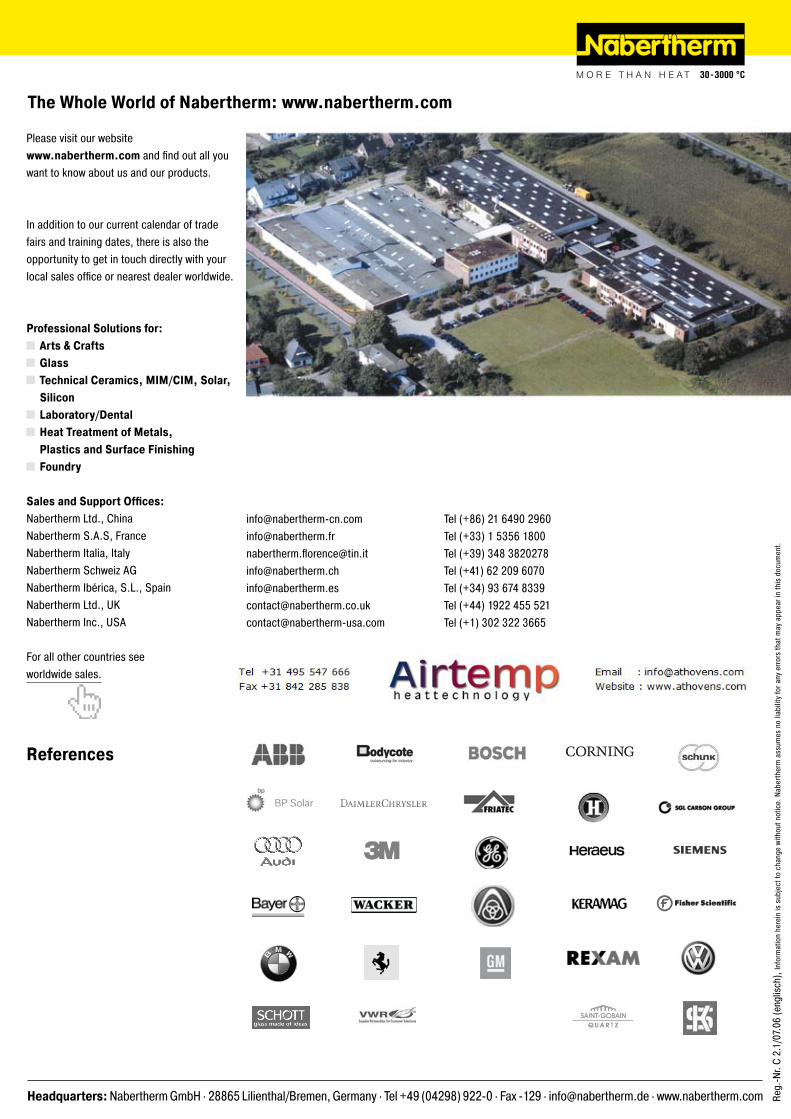
The Whole World of Nabertherm: www.nabertherm.com
References
Headquarters: Nabertherm GmbH . �8865 Lilienthal/Bremen, Germany . Tel +49 (04�98) 9��-0 . Fax -1�9 . [email protected] . www.nabertherm.com