Embed Size (px)
Citation preview
FrequencyInverter
FR-S 500EC/ECR
Technical Catalogue
MITSUBISHI ELECTRIC
2004
+-
118
5
128
ø5
118
348
4,5
10
96
M4
96
110
158
158
168
4,5
5
9,5
118
D2
8
35
4,5
10
56
M4
56
70
158
RUN
RUN
SETMODE
PU
EXT
PUEXT
STOP
RESET
MITSUBISHIFR-S500
2 MITSUBISHI ELECTRICFR-S 500 EC/ECR
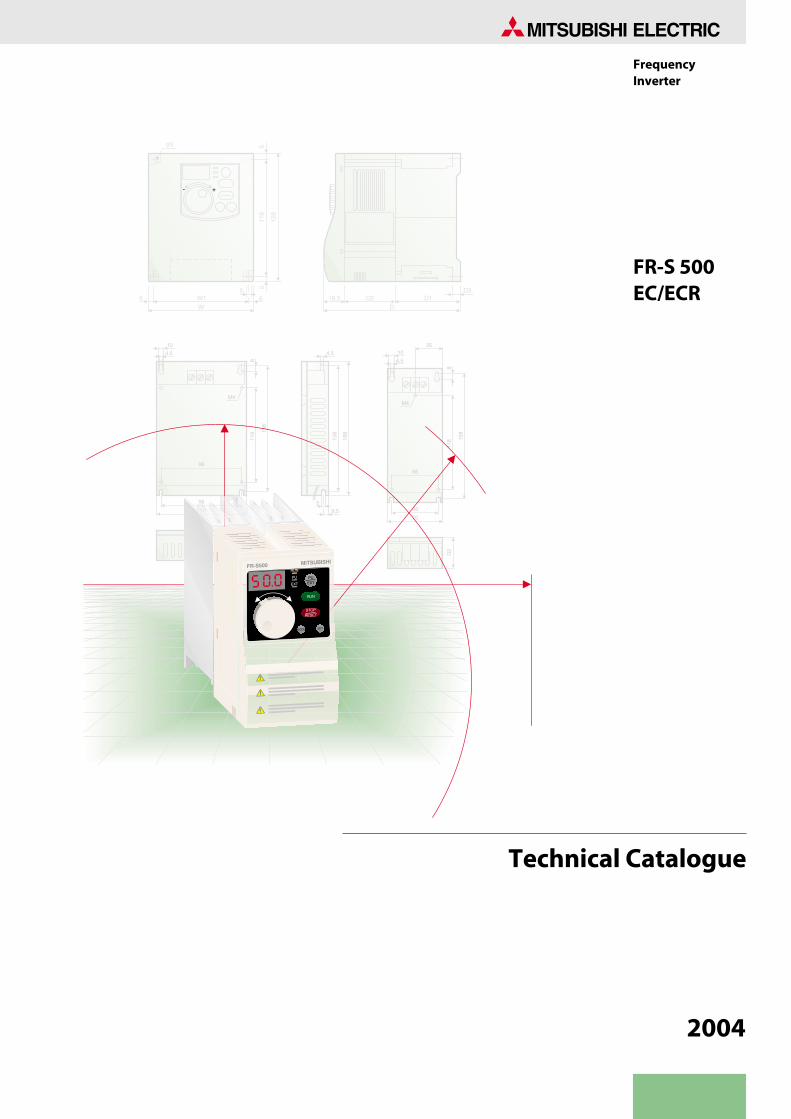
The inverters are available in the performance range from0.2 to 1.5 kW for operation with single-phase 200 to 240 V ACpower supplies (50/60 Hz) and for capacities of 0.4 kW to 3.7 kWwith three-phase 380 to 480 V AC power supplies (50/60 Hz).
Additional servicesYou will find current information on updates, alterations, new items, and technical support on MITSUBISHI ELECTRIC's web pages(www.mitsubishi-automation.com).
The products section of the MITSUBISHI home site includes various documentations of the whole product range by MITSUBISHIELECTRIC as well as the current version of this catalogue on hand. All manuals and catalogues can be downloaded.The content is updated daily and to date is provided in German and English.
About this product catalogueThis catalogue is periodically updated due to product range enlargement, technical changes or new or changed features.Texts, figures and diagrams shown in this product catalogue are intended exclusively for explanation and assistance in planning and orderingthe frequency inverter series FR-S 500 EC/ECR and the associated accessories. Only the manuals supplied with the devices are relevant forinstallation, commissioning and handling of the devices and the accessories. The information given in these manuals must be read beforeinstallation and commissioning of the devices or software.
Should questions arise with regard to the planning of devices described in this product catalogue, do not hesitate to contact MITSUBISHIELECTRIC EUROPE B.V. in Ratingen (Germany) or one of its distributors (see cover page).
© MITSUBISHI ELECTRIC EUROPE B.V. 01/2004 (5th edition - version E)
Technical
Catalogues
Dial in Your
Advantage
Further Publications within the Factory Automation Range
FR-S 500 EC Frequency Inverters
Technical catalogues FR-A 500, FR-F 500 and FR-S 500
Product catalogues for frequency inverters and accessoriesof the FR-A 500 (L-G) EC, FR-F 500L and FR-S 500 series
Technical catalogues MELSERVO and Motion Controllers
Product catalogues for MR-J2S series amplifiers, servo motorsand motion controllers with SSCNET connection
Technical catalogues PLC and HMI
Product catalogues for programmable logic controllers,operator terminals, software, and accessories of theMELSEC PLC series
Technical catalogue Networks
Product catalogue for Master and Slave modules as well as acces-sories for the use of programmable logic controllers and frequencyinverters in open and MELSEC networks (art. no. 136730)
3FR-S 500 EC/ECR
CONTENTS
FREQUENCY INVERTER FR-S 500 EC/ECR
SYSTEM DESCRIPTION
Introduction of the FR-S series . . . . . . . . . . . . . . . . . . . . . . . . . . . . . . . . . . . . . . . . . . . . . . . . . . . . . . . . . . . . . . . . . . . . . . . . . . . . . 4 Equipment and configuration . . . . . . . . . . . . . . . . . . . . . . . . . . . . . . . . . . . . . . . . . . . . . . . . . . . . . . . . . . . . . . . . . . . 5 The integrated control panel . . . . . . . . . . . . . . . . . . . . . . . . . . . . . . . . . . . . . . . . . . . . . . . . . . . . . . . . . . . . . . . . . . . . . . . . . . . . . . 6 Specifications . . . . . . . . . . . . . . . . . . . . . . . . . . . . . . . . . . . . . . . . . . . . . . . . . . . . . . . . . . . . . . . . . . . . . . . . . . . . . . . . . . . . . . . . . . . . . 8 Terminal assignment. . . . . . . . . . . . . . . . . . . . . . . . . . . . . . . . . . . . . . . . . . . . . . . . . . . . . . . . . . . . . . . . . . . . . . . . . . . . . . . . . . . . . 10 Optional parameter unit FR-PU04. . . . . . . . . . . . . . . . . . . . . . . . . . . . . . . . . . . . . . . . . . . . . . . . . . . . . . . . . . . . . . . . . . . . . . . . . 12
PARAMETERS + PROTECTIVE FUNCTIONS
Overview of parameters. . . . . . . . . . . . . . . . . . . . . . . . . . . . . . . . . . . . . . . . . . . . . . . . . . . . . . . . . . . . . . . . . . . . . . . . . . . . . . . . . . 14 Overview of protective functions . . . . . . . . . . . . . . . . . . . . . . . . . . . . . . . . . . . . . . . . . . . . . . . . . . . . . . . . . . . . . . . . . . . . . . . . . 17 Activating a protective function and resetting methods . . . . . . . . . . . . . . . . . . . . . . . . . . . . . . . . . . . . . . . . . . . . . . . . . . . 18 Sample applications . . . . . . . . . . . . . . . . . . . . . . . . . . . . . . . . . . . . . . . . . . . . . . . . . . . . . . . . . . . . . . . . . . . . . . . . . . . . . . . . . . . . . 19
ACCESSORIES
Overview of options . . . . . . . . . . . . . . . . . . . . . . . . . . . . . . . . . . . . . . . . . . . . . . . . . . . . . . . . . . . . . . . . . . . . . . . . . . . . . . . . . . . . . 20 Noise filters . . . . . . . . . . . . . . . . . . . . . . . . . . . . . . . . . . . . . . . . . . . . . . . . . . . . . . . . . . . . . . . . . . . . . . . . . . . . . . . . . . . . . . . . . . . . . . 21 Brake units . . . . . . . . . . . . . . . . . . . . . . . . . . . . . . . . . . . . . . . . . . . . . . . . . . . . . . . . . . . . . . . . . . . . . . . . . . . . . . . . . . . . . . . . . . . . . . 21
DIMENSIONS
Parameter unit. . . . . . . . . . . . . . . . . . . . . . . . . . . . . . . . . . . . . . . . . . . . . . . . . . . . . . . . . . . . . . . . . . . . . . . . . . . . . . . . . . . . . . . . . . . 22 Frequency inverters. . . . . . . . . . . . . . . . . . . . . . . . . . . . . . . . . . . . . . . . . . . . . . . . . . . . . . . . . . . . . . . . . . . . . . . . . . . . . . . . . . . . . . 23 Noise filters . . . . . . . . . . . . . . . . . . . . . . . . . . . . . . . . . . . . . . . . . . . . . . . . . . . . . . . . . . . . . . . . . . . . . . . . . . . . . . . . . . . . . . . . . . . . . . 24 Brake units . . . . . . . . . . . . . . . . . . . . . . . . . . . . . . . . . . . . . . . . . . . . . . . . . . . . . . . . . . . . . . . . . . . . . . . . . . . . . . . . . . . . . . . . . . . . . . 25
APPENDIX
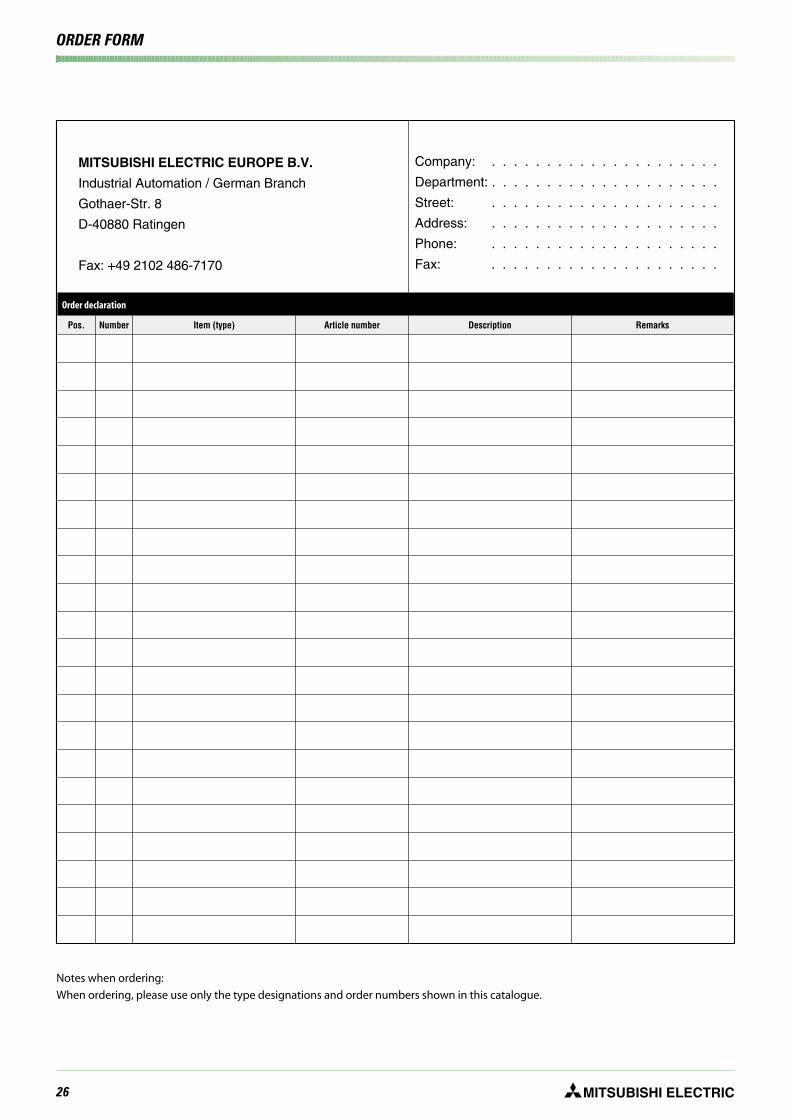
Order form . . . . . . . . . . . . . . . . . . . . . . . . . . . . . . . . . . . . . . . . . . . . . . . . . . . . . . . . . . . . . . . . . . . . . . . . . . . . . . . . . . . . . . . . . . . . . . 26 Index . . . . . . . . . . . . . . . . . . . . . . . . . . . . . . . . . . . . . . . . . . . . . . . . . . . . . . . . . . . . . . . . . . . . . . . . . . . . . . . . . . . . . . . . . . . . . . . . . . . . 27
4 MITSUBISHI ELECTRICFR-S 500 EC/ECR
SYSTEM DESCRIPTION
The Frequency Inverter FR-S 500 EC/ECR
RUN
RUN
SETMODE
PU
EXT
PUEXT
STOP
RESET
S500MITSUBISHI
RUN
RUN
SETMODE
PU
EXT
PUEXT
STOP
RESET
FR-S500 MITSUBISHI
R
RC
DIN ISO 9001 /EN 29001
Zertifikat: 09 100 4371
SELV
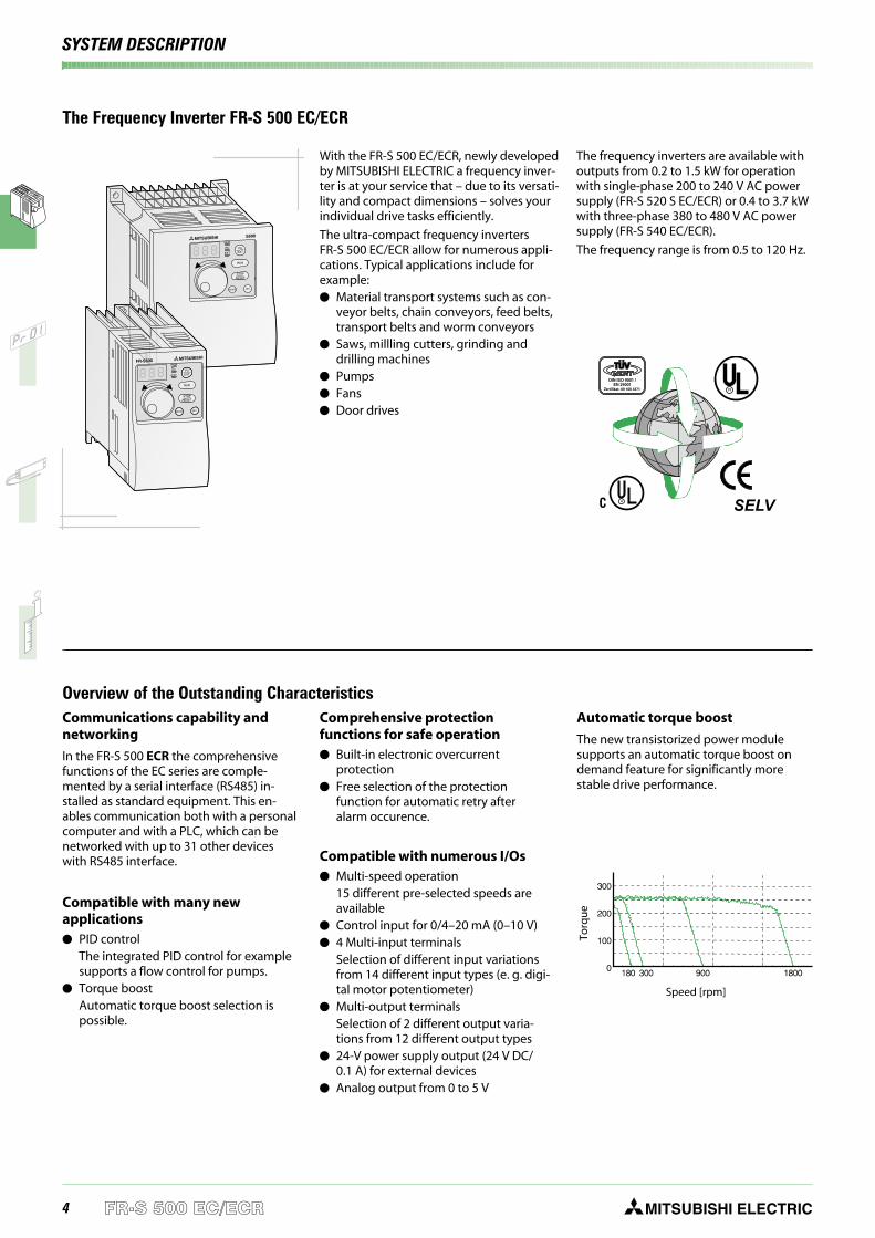
Overview of the Outstanding CharacteristicsCommunications capability andnetworking
In the FR-S 500 ECR the comprehensivefunctions of the EC series are comple-mented by a serial interface (RS485) in-stalled as standard equipment. This en-ables communication both with a personalcomputer and with a PLC, which can benetworked with up to 31 other deviceswith RS485 interface.
Compatible with many newapplications PID control
The integrated PID control for examplesupports a flow control for pumps.
Torque boostAutomatic torque boost selection ispossible.
Comprehensive protectionfunctions for safe operation Built-in electronic overcurrent
protection Free selection of the protection
function for automatic retry afteralarm occurence.
Compatible with numerous I/Os Multi-speed operation
15 different pre-selected speeds areavailable
Control input for 0/4–20 mA (0–10 V) 4 Multi-input terminals
Selection of different input variationsfrom 14 different input types (e. g. digi-tal motor potentiometer)
Multi-output terminalsSelection of 2 different output varia-tions from 12 different output types
24-V power supply output (24 V DC/0.1 A) for external devices
Analog output from 0 to 5 V
Automatic torque boost
The new transistorized power modulesupports an automatic torque boost ondemand feature for significantly morestable drive performance.
With the FR-S 500 EC/ECR, newly developedby MITSUBISHI ELECTRIC a frequency inver-ter is at your service that – due to its versati-lity and compact dimensions – solves yourindividual drive tasks efficiently.
The ultra-compact frequency invertersFR-S 500 EC/ECR allow for numerous appli-cations. Typical applications include forexample: Material transport systems such as con-
veyor belts, chain conveyors, feed belts,transport belts and worm conveyors
Saws, millling cutters, grinding anddrilling machines
Pumps Fans Door drives
The frequency inverters are available withoutputs from 0.2 to 1.5 kW for operationwith single-phase 200 to 240 V AC powersupply (FR-S 520 S EC/ECR) or 0.4 to 3.7 kWwith three-phase 380 to 480 V AC powersupply (FR-S 540 EC/ECR).
The frequency range is from 0.5 to 120 Hz.
Speed [rpm]
Torq
ue

5MITSUBISHI ELECTRIC FR-S 500 EC/ECR
SYSTEM DESCRIPTION
User-friendly Operation
Easy operation
The integrated control panel provides aquick and easy operation of the frequencyinverter and displays several operationalsignals and error messages. The "DigitalDial" provides a far more quick and directaccess to all important drive parametersthan conventional keys would allow.
In addition, for example the speed of theconnected motor can be continuouslycontrolled directly.
For a remote control of the inverter amongothers the parameter unit FR-PU04 isavailable. It provides a long-life backlightLC display. Operational data is inputdirectly via the numeric keypad.
Eight different selectable languages aresupported by the display.
The integrated copy function transfers theentire parameter settings to other invertersand thus shortens the initialisation timesignificantly.
RUN
PU
EXT
RUN
STOP
RESET
MODE SET
PUEXT
Simplified MaintenanceEasy access to cooling fans
The easily accessible cooling fans can bereplaced quickly and easily, if required.
The integrated cooling fan can beswitched OFF automatically in stand-byoperation to increase its lifetime signifi-cantly.
Easy installation and maintenance
Since the control and power terminal blockis easy of access, the installation and main-tenance of the inverter is also very easy.
All connection points are designed asscrew terminals.
The housing includes a cable routingfacility which can be removed for in-stalling.
SINK
R/L S/L T/L3 U V W
MODE
RUN
STOPRESET
PUEXT
SET
A B CSOURCE
AMRHRMRL
STRSTF
45210RUN
SEPC
SDSD
RUN
RUN
SETMODE
PU
EXT
PU
+-
EXT
STOP
RESET
SINK
A B C
SOURCE
PC SE RUN
AMRHRMRLSTR
SD
10 2 5 4
FR-S 500 EC/ECR
SINK
R/L S/L T/L3 U V W
MODE
RUN
STOPRESET
PUEXT
SET
A B CSOURCE
AMRHRMRL
STRSTF
45210RUN
SEPC
SDSD
EXT PU
FWD
REV
STOP
RESETWRITEREAD
MON
HELP
7
4
1
0
2 3
8
5 6
9
SET
SHIFT ESC
FR-PU-04 PARAMETER UNIT
- - - STOP EXT50 00 Hz
FR-PU04
By default, only the 12 most importantparameters are activated to ensure a quickparameterizing. If required, all parameterscan be easily accessed.
Integratedcontrol panel
In addition to control panel operation thefrequency inverter can also be connectedto a standard PC via an RS-485 port andoperated from the PC with the optionalVFD setup software package (see page 20).Version 2.4 and above of this package rununder Windows® 95, 98, Me and XP andalso under Windows® NT and 2000. Usingthis software you can configure, operateand monitor multiple frequency invertersin a network or directly from a single PC ornotebook computer.
6 MITSUBISHI ELECTRICFR-S 500 EC/ECR
SYSTEM DESCRIPTION
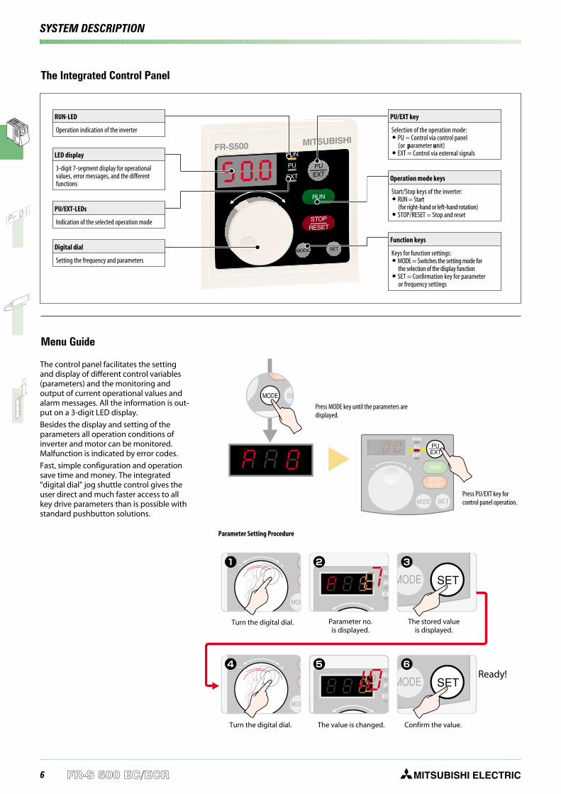
The Integrated Control Panel
Einstellrad drehen Der Wert wird geändert
Fertig!
Bestätigung
Menu Guide
The control panel facilitates the settingand display of different control variables(parameters) and the monitoring andoutput of current operational values andalarm messages. All the information is out-put on a 3-digit LED display.
Besides the display and setting of theparameters all operation conditions ofinverter and motor can be monitored.Malfunction is indicated by error codes.
Fast, simple configuration and operationsave time and money. The integrated"digital dial" jog shuttle control gives theuser direct and much faster access to allkey drive parameters than is possible withstandard pushbutton solutions.
RUN
RUN
SETMODE
PU
EXT
PUEXT
STOP
RESET
MITSUBISHIFR-S500
PU/EXT key
Selection of the operation mode: PU = Control via control panel
(or parameter unit) EXT = Control via external signals
Operation mode keys
Start/Stop keys of the inverter: RUN = Start
(for right-hand or left-hand rotation) STOP/RESET = Stop and reset
Function keys
Keys for function settings: MODE = Switches the setting mode for
the selection of the display function SET = Confirmation key for parameter
or frequency settings
Press MODE key until the parameters aredisplayed.
Press PU/EXT key forcontrol panel operation.
Parameter Setting Procedure
Confirm the value.The value is changed.Turn the digital dial.
Turn the digital dial. Parameter no.is displayed.
The stored valueis displayed.
Ready!
RUN-LED
Operation indication of the inverter
LED display
3-digit 7-segment display for operationalvalues, error messages, and the differentfunctions
PU/EXT-LEDs
Indication of the selected operation mode
Digital dial
Setting the frequency and parameters
7MITSUBISHI ELECTRIC FR-S 500 EC/ECR
SYSTEM DESCRIPTION
EMC compatibility
Regarding its electromagnetic compatibil-ity the frequency inverter FR-S 500 EC/ECRcomplies with the European EMC direc-tives. To meet these standards speciallyadjusted compact noise filters have beendeveloped for each performace range.These noise filters can be mounted simplyon or under the inverter.
For details refer to page 21.
By connecting an optional converter chokecoil harmonic feedback into the mains sup-ply is suppressed.
Standards
The devices of the FR-S 500 EC/ECR productline are designed to be used world-widewithout further effort or certifications. Compliant with world-wide standards
CE, UL, cUL Selectable sink or source logic
The logic for input and output signalscan be freely selected. The result is aflexible and easy customization of theunits to the needs of the world market.
Extended input voltage rangeFR-S 520 EC/ECR: 1~ 200–240 V; 50/60 Hz;FR-S 540 EC/ECR: 3~ 380–480 V; 50/60 Hz;Tolerance: −15 %; +10 %
Multi-language parameter unit(8 languages) optionally available
Due to the integrated PID control thefrequency inverter for instance can beused for temperature control withoutfurther requirements.
All inverters are equipped with an in-rush current limiter protecting theconnected components.
MS-Windows compatible world-widestandardized multi-language paramete-rizing software (VFD-Setup).
The FR-S 500 EC/ECR is a world productcomplying with all relevant standards andeasily adopting to the according needs of acountry.
Environmentally Friendly Operation
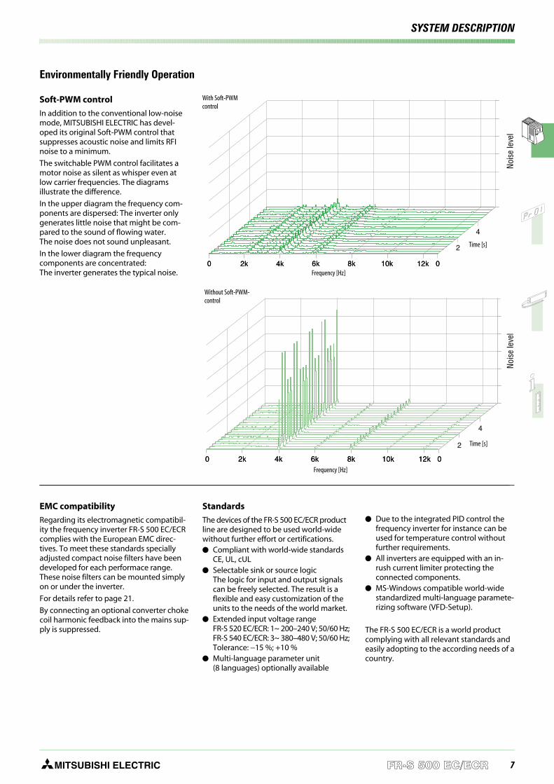
Soft-PWM control
In addition to the conventional low-noisemode, MITSUBISHI ELECTRIC has devel-oped its original Soft-PWM control thatsuppresses acoustic noise and limits RFInoise to a minimum.
The switchable PWM control facilitates amotor noise as silent as whisper even atlow carrier frequencies. The diagramsillustrate the difference.
In the upper diagram the frequency com-ponents are dispersed: The inverter onlygenerates little noise that might be com-pared to the sound of flowing water.The noise does not sound unpleasant.
In the lower diagram the frequencycomponents are concentrated:The inverter generates the typical noise.
With Soft-PWMcontrol
Frequency [Hz]
Time [s]
Nois
ele
vel
Without Soft-PWM-control
Frequency [Hz]
Time [s]
Nois
ele
vel
8 MITSUBISHI ELECTRICFR-S 500 EC/ECR
SYSTEM DESCRIPTION
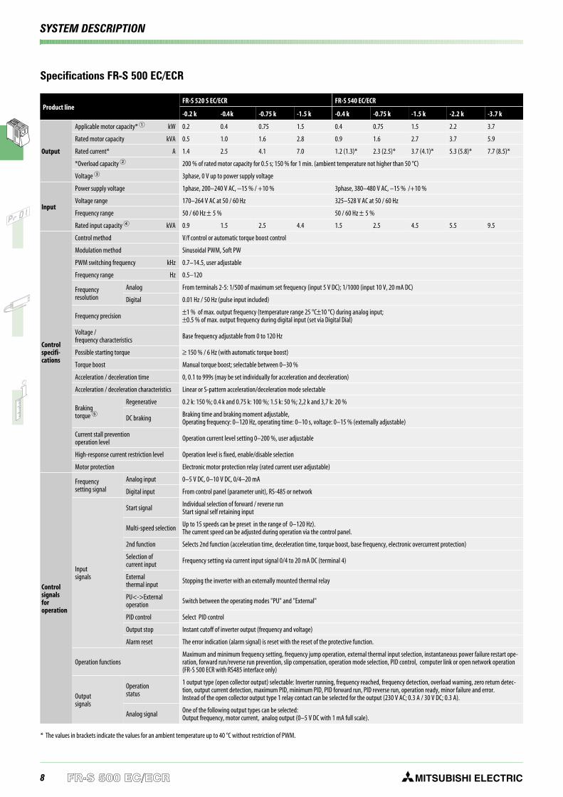
Product lineFR-S 520 S EC/ECR FR-S 540 EC/ECR
-0.2 k -0.4k -0.75 k -1.5 k -0.4 k -0.75 k -1.5 k -2.2 k -3.7 k
Output
Applicable motor capacity* kW 0.2 0.4 0.75 1.5 0.4 0.75 1.5 2.2 3.7
Rated motor capacity kVA 0.5 1.0 1.6 2.8 0.9 1.6 2.7 3.7 5.9
Rated current* A 1.4 2.5 4.1 7.0 1.2 (1.3)* 2.3 (2.5)* 3.7 (4.1)* 5.3 (5.8)* 7.7 (8.5)*
*Overload capacity 200 % of rated motor capacity for 0.5 s; 150 % for 1 min. (ambient temperature not higher than 50 °C)
Voltage 3phase, 0 V up to power supply voltage
Input
Power supply voltage 1phase, 200–240 V AC, −15 % / +10 % 3phase, 380–480 V AC, –15 % /+10 %
Voltage range 170–264 V AC at 50 / 60 Hz 325–528 V AC at 50 / 60 Hz
Frequency range 50 / 60 Hz ± 5 % 50 / 60 Hz ± 5 %
Rated input capacity kVA 0.9 1.5 2.5 4.4 1.5 2.5 4.5 5.5 9.5
Controlspecifi-cations
Control method V/f control or automatic torque boost control
Modulation method Sinusoidal PWM, Soft PW
PWM switching frequency kHz 0.7–14.5, user adjustable
Frequency range Hz 0.5–120
Frequencyresolution
Analog From terminals 2-5: 1/500 of maximum set frequency (input 5 V DC); 1/1000 (input 10 V, 20 mA DC)
Digital 0.01 Hz / 50 Hz (pulse input included)
Frequency precision ±1 % of max. output frequency (temperature range 25 °C±10 °C) during analog input;±0.5 % of max. output frequency during digital input (set via Digital Dial)
Voltage /frequency characteristics Base frequency adjustable from 0 to 120 Hz
Possible starting torque ≥ 150 % / 6 Hz (with automatic torque boost)
Torque boost Manual torque boost; selectable between 0–30 %
Acceleration / deceleration time 0, 0.1 to 999s (may be set individually for acceleration and deceleration)
Acceleration / deceleration characteristics Linear or S-pattern acceleration/deceleration mode selectable
Brakingtorque
Regenerative 0.2 k: 150 %; 0.4 k and 0.75 k: 100 %; 1.5 k: 50 %; 2,2 k and 3,7 k: 20 %
DC braking Braking time and braking moment adjustable,Operating frequency: 0–120 Hz, operating time: 0–10 s, voltage: 0–15 % (externally adjustable)
Current stall preventionoperation level Operation current level setting 0–200 %, user adjustable
High-response current restriction level Operation level is fixed, enable/disable selection
Motor protection Electronic motor protection relay (rated current user adjustable)
Controlsignalsforoperation
Frequencysetting signal
Analog input 0–5 V DC, 0–10 V DC, 0/4–20 mA
Digital input From control panel (parameter unit), RS-485 or network
Inputsignals
Start signal Individual selection of forward / reverse runStart signal self retaining input
Multi-speed selection Up to 15 speeds can be preset in the range of 0–120 Hz).The current speed can be adjusted during operation via the control panel.
2nd function Selects 2nd function (acceleration time, deceleration time, torque boost, base frequency, electronic overcurrent protection)
Selection ofcurrent input Frequency setting via current input signal 0/4 to 20 mA DC (terminal 4)
Externalthermal input Stopping the inverter with an externally mounted thermal relay
PU<->Externaloperation Switch between the operating modes "PU" and "External"
PID control Select PID control
Output stop Instant cutoff of inverter output (frequency and voltage)
Alarm reset The error indication (alarm signal) is reset with the reset of the protective function.
Operation functionsMaximum and minimum frequency setting, frequency jump operation, external thermal input selection, instantaneous power failure restart ope-ration, forward run/reverse run prevention, slip compensation, operation mode selection, PID control, computer link or open network operation(FR-S 500 ECR with RS485 interface only)
Outputsignals
Operationstatus
1 output type (open collector output) selectable: Inverter running, frequency reached, frequency detection, overload warning, zero return detec-tion, output current detection, maximum PID, minimum PID, PID forward run, PID reverse run, operation ready, minor failure and error.Instead of the open collector output type 1 relay contact can be selected for the output (230 V AC; 0.3 A / 30 V DC; 0.3 A).
Analog signal One of the following output types can be selected:Output frequency, motor current, analog output (0–5 V DC with 1 mA full scale).
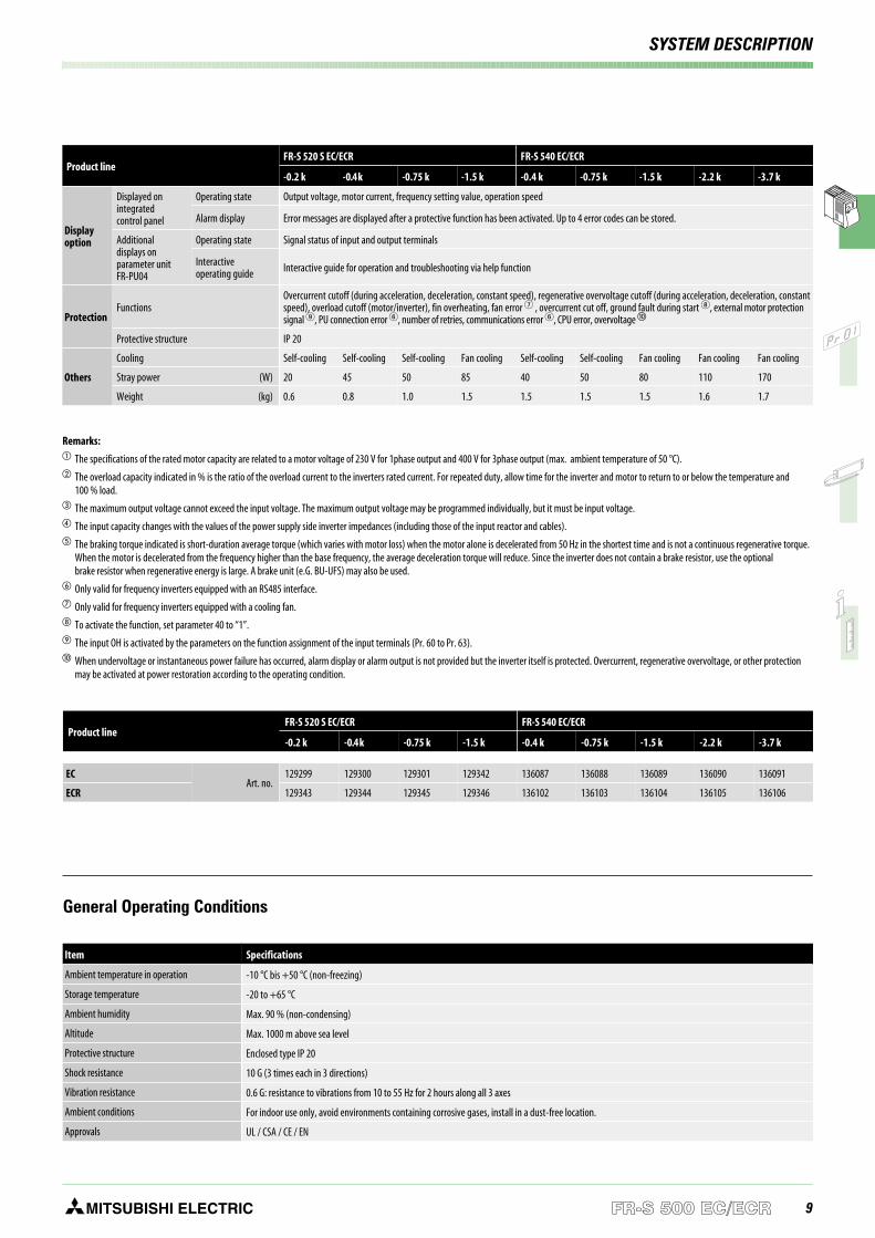
Specifications FR-S 500 EC/ECR
* The values in brackets indicate the values for an ambient temperature up to 40 °C without restriction of PWM.
9MITSUBISHI ELECTRIC FR-S 500 EC/ECR
SYSTEM DESCRIPTION
General Operating Conditions
Item Specifications
Ambient temperature in operation -10 °C bis +50 °C (non-freezing)
Storage temperature -20 to +65 °C
Ambient humidity Max. 90 % (non-condensing)
Altitude Max. 1000 m above sea level
Protective structure Enclosed type IP 20
Shock resistance 10 G (3 times each in 3 directions)
Vibration resistance 0.6 G: resistance to vibrations from 10 to 55 Hz for 2 hours along all 3 axes
Ambient conditions For indoor use only, avoid environments containing corrosive gases, install in a dust-free location.
Approvals UL / CSA / CE / EN
Product lineFR-S 520 S EC/ECR FR-S 540 EC/ECR
-0.2 k -0.4k -0.75 k -1.5 k -0.4 k -0.75 k -1.5 k -2.2 k -3.7 k
ECArt. no.
129299 129300 129301 129342 136087 136088 136089 136090 136091
ECR 129343 129344 129345 129346 136102 136103 136104 136105 136106
Remarks: The specifications of the rated motor capacity are related to a motor voltage of 230 V for 1phase output and 400 V for 3phase output (max. ambient temperature of 50 °C). The overload capacity indicated in % is the ratio of the overload current to the inverters rated current. For repeated duty, allow time for the inverter and motor to return to or below the temperature and
100 % load. The maximum output voltage cannot exceed the input voltage. The maximum output voltage may be programmed individually, but it must be input voltage. The input capacity changes with the values of the power supply side inverter impedances (including those of the input reactor and cables). The braking torque indicated is short-duration average torque (which varies with motor loss) when the motor alone is decelerated from 50 Hz in the shortest time and is not a continuous regenerative torque.
When the motor is decelerated from the frequency higher than the base frequency, the average deceleration torque will reduce. Since the inverter does not contain a brake resistor, use the optionalbrake resistor when regenerative energy is large. A brake unit (e.G. BU-UFS) may also be used.
Only valid for frequency inverters equipped with an RS485 interface. Only valid for frequency inverters equipped with a cooling fan. To activate the function, set parameter 40 to “1”. The input OH is activated by the parameters on the function assignment of the input terminals (Pr. 60 to Pr. 63). When undervoltage or instantaneous power failure has occurred, alarm display or alarm output is not provided but the inverter itself is protected. Overcurrent, regenerative overvoltage, or other protection
may be activated at power restoration according to the operating condition.
Product lineFR-S 520 S EC/ECR FR-S 540 EC/ECR
-0.2 k -0.4k -0.75 k -1.5 k -0.4 k -0.75 k -1.5 k -2.2 k -3.7 k
Displayoption
Displayed onintegratedcontrol panel
Operating state Output voltage, motor current, frequency setting value, operation speed
Alarm display Error messages are displayed after a protective function has been activated. Up to 4 error codes can be stored.
Additionaldisplays onparameter unitFR-PU04
Operating state Signal status of input and output terminals
Interactiveoperating guide Interactive guide for operation and troubleshooting via help function
ProtectionFunctions
Overcurrent cutoff (during acceleration, deceleration, constant speed), regenerative overvoltage cutoff (during acceleration, deceleration, constantspeed), overload cutoff (motor/inverter), fin overheating, fan error , overcurrent cut off, ground fault during start , external motor protectionsignal , PU connection error , number of retries, communications error , CPU error, overvoltage
Protective structure IP 20
Others
Cooling Self-cooling Self-cooling Self-cooling Fan cooling Self-cooling Self-cooling Fan cooling Fan cooling Fan cooling
Stray power (W) 20 45 50 85 40 50 80 110 170
Weight (kg) 0.6 0.8 1.0 1.5 1.5 1.5 1.5 1.6 1.7
10 MITSUBISHI ELECTRICFR-S 500 EC/ECR
SYSTEM DESCRIPTION
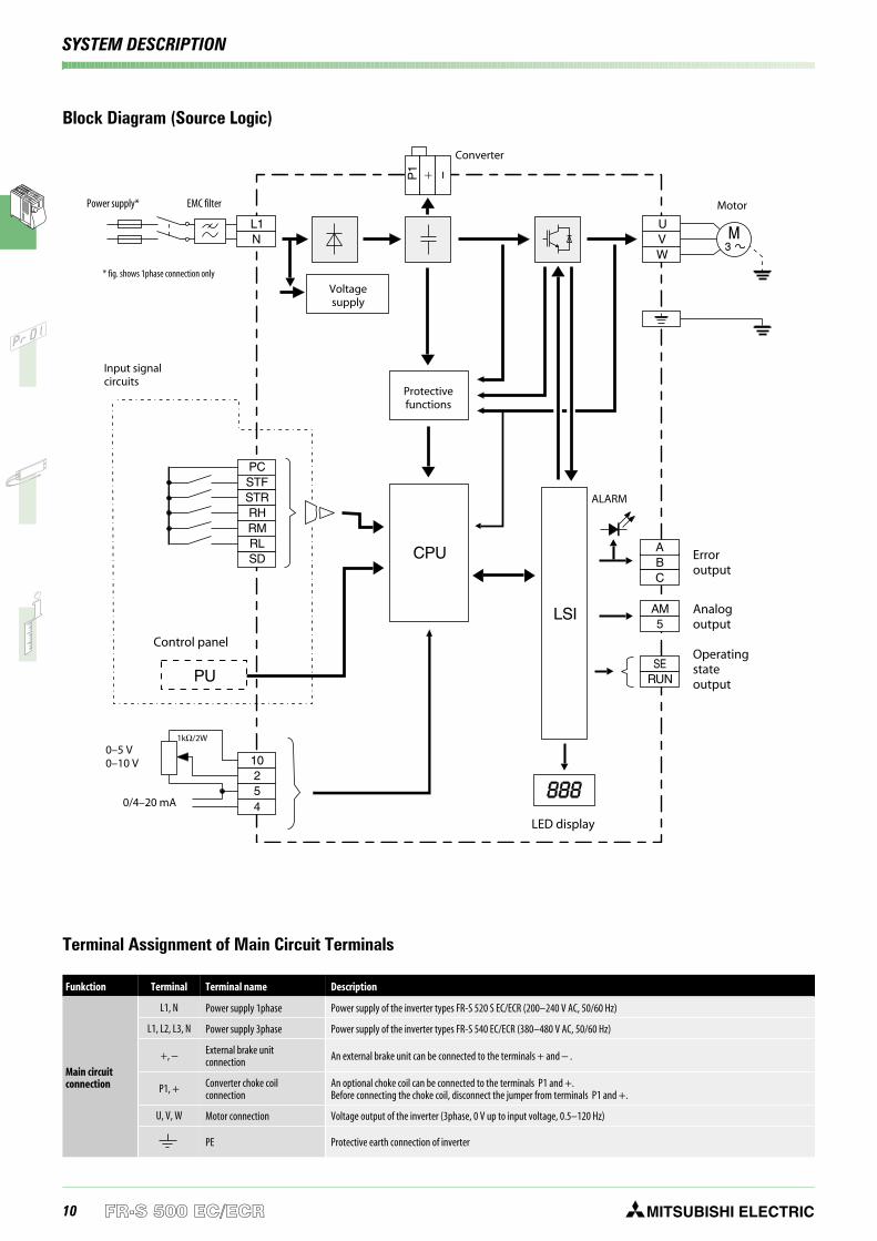
Block Diagram (Source Logic)
Funkction Terminal Terminal name Description
Main circuitconnection
L1, N Power supply 1phase Power supply of the inverter types FR-S 520 S EC/ECR (200–240 V AC, 50/60 Hz)
L1, L2, L3, N Power supply 3phase Power supply of the inverter types FR-S 540 EC/ECR (380–480 V AC, 50/60 Hz)
+, − External brake unitconnection An external brake unit can be connected to the terminals + and − .
P1, + Converter choke coilconnection
An optional choke coil can be connected to the terminals P1 and +.Before connecting the choke coil, disconnect the jumper from terminals P1 and +.
U, V, W Motor connection Voltage output of the inverter (3phase, 0 V up to input voltage, 0.5–120 Hz)
PE Protective earth connection of inverter
Terminal Assignment of Main Circuit Terminals
Power supply*
Input signalcircuits
Protectivefunctions
Voltagesupply
Control panel
LED display
0–5 V0–10 V
0/4–20 mA
Converter
Motor
ALARM
Erroroutput
Analogoutput
Operatingstateoutput
1kΩ/2W
EMC filter
* fig. shows 1phase connection only
11MITSUBISHI ELECTRIC FR-S 500 EC/ECR
SYSTEM DESCRIPTION
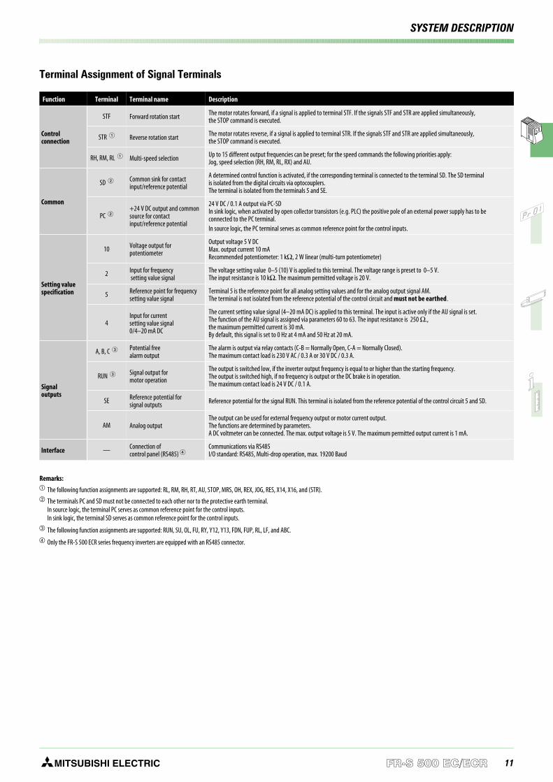
Terminal Assignment of Signal Terminals
Function Terminal Terminal name Description
Controlconnection
STF Forward rotation start The motor rotates forward, if a signal is applied to terminal STF. If the signals STF and STR are applied simultaneously,the STOP command is executed.
STR Reverse rotation start The motor rotates reverse, if a signal is applied to terminal STR. If the signals STF and STR are applied simultaneously,the STOP command is executed.
RH, RM, RL Multi-speed selection Up to 15 different output frequencies can be preset; for the speed commands the following priorities apply:Jog, speed selection (RH, RM, RL, RX) and AU.
Common
SD Common sink for contactinput/reference potential
A determined control function is activated, if the corresponding terminal is connected to the terminal SD. The SD terminalis isolated from the digital circuits via optocouplers.The terminal is isolated from the terminals 5 and SE.
PC +24 V DC output and commonsource for contactinput/reference potential
24 V DC / 0.1 A output via PC-SDIn sink logic, when activated by open collector transistors (e.g. PLC) the positive pole of an external power supply has to beconnected to the PC terminal.In source logic, the PC terminal serves as common reference point for the control inputs.
Setting valuespecification
10 Voltage output forpotentiometer
Output voltage 5 V DCMax. output current 10 mARecommended potentiometer: 1 kΩ, 2 W linear (multi-turn potentiometer)
2 Input for frequencysetting value signal
The voltage setting value 0–5 (10) V is applied to this terminal. The voltage range is preset to 0–5 V.The input resistance is 10 kΩ. The maximum permitted voltage is 20 V.
5 Reference point for frequencysetting value signal
Terminal 5 is the reference point for all analog setting values and for the analog output signal AM.The terminal is not isolated from the reference potential of the control circuit and must not be earthed.
4Input for currentsetting value signal0/4–20 mA DC
The current setting value signal (4–20 mA DC) is applied to this terminal. The input is active only if the AU signal is set.The function of the AU signal is assigned via parameters 60 to 63. The input resistance is 250 Ω.,the maximum permitted current is 30 mA.By default, this signal is set to 0 Hz at 4 mA and 50 Hz at 20 mA.
Signaloutputs
A, B, C Potential freealarm output
The alarm is output via relay contacts (C-B = Normally Open, C-A = Normally Closed).The maximum contact load is 230 V AC / 0.3 A or 30 V DC / 0.3 A.
RUN Signal output formotor operation
The output is switched low, if the inverter output frequency is equal to or higher than the starting frequency.The output is switched high, if no frequency is output or the DC brake is in operation.The maximum contact load is 24 V DC / 0.1 A.
SE Reference potential forsignal outputs Reference potential for the signal RUN. This terminal is isolated from the reference potential of the control circuit 5 and SD.
AM Analog outputThe output can be used for external frequency output or motor current output.The functions are determined by parameters.A DC voltmeter can be connected. The max. output voltage is 5 V. The maximum permitted output current is 1 mA.
Interface — Connection ofcontrol panel (RS485)
Communications via RS485I/O standard: RS485, Multi-drop operation, max. 19200 Baud
Remarks: The following function assignments are supported: RL, RM, RH, RT, AU, STOP, MRS, OH, REX, JOG, RES, X14, X16, and (STR). The terminals PC and SD must not be connected to each other nor to the protective earth terminal.
In source logic, the terminal PC serves as common reference point for the control inputs.In sink logic, the terminal SD serves as common reference point for the control inputs.
The following function assignments are supported: RUN, SU, OL, FU, RY, Y12, Y13, FDN, FUP, RL, LF, and ABC. Only the FR-S 500 ECR series frequency inverters are equipped with an RS485 connector.
12 MITSUBISHI ELECTRICFR-S 500 EC/ECR
OPERATION
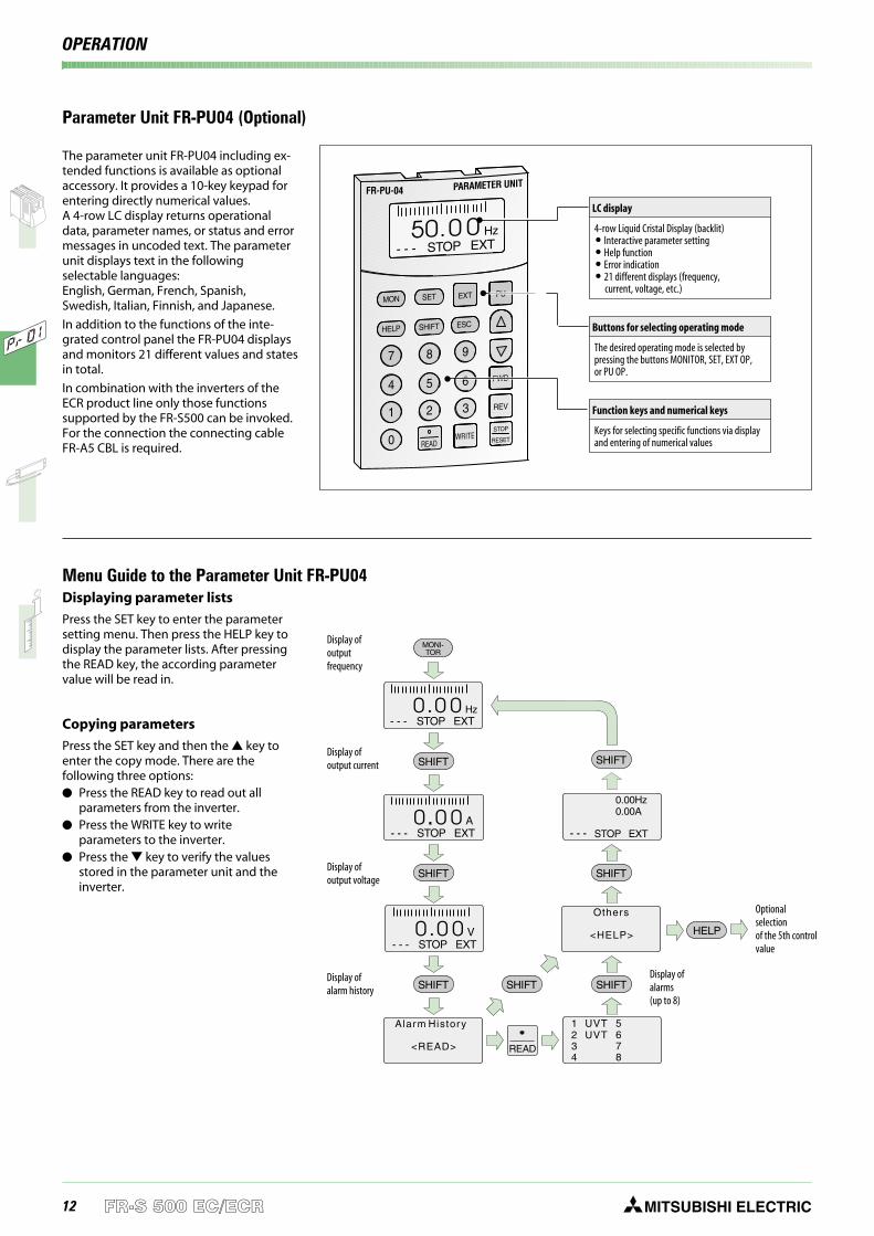
Parameter Unit FR-PU04 (Optional)
EXT PU
FWD
REV
STOP
RESETWRITEREAD
MON
HELP
7
4
1
0
2 3
8
5 6
9
SET
SHIFT ESC
FR-PU-04 PARAMETER UNIT
- - - STOP EXT50 00 Hz
LC display
4-row Liquid Cristal Display (backlit) Interactive parameter setting Help function Error indication 21 different displays (frequency,
current, voltage, etc.)
Buttons for selecting operating mode
The desired operating mode is selected bypressing the buttons MONITOR, SET, EXT OP,or PU OP.
Function keys and numerical keys
Keys for selecting specific functions via displayand entering of numerical values
MONI-TOR
Others
<HELP>
Alarm History
<READ>
1 5UVT2 6UVT3 74 8
SHIFT
SHIFT SHIFT
SHIFT
SHIFT SHIFT SHIFT
- - - STOP EXT0 00 Hz
- - -
- - -
STOP
STOP
EXT
EXT
A
V
0
0
0
0
0
0
READ
HELP
0.00Hz0.00A
STOP EXT- - -
Display ofoutputfrequency
Display ofoutput current
Display ofoutput voltage
Display ofalarm history
Display ofalarms(up to 8)
Optionalselectionof the 5th controlvalue
Displaying parameter lists
Press the SET key to enter the parametersetting menu. Then press the HELP key todisplay the parameter lists. After pressingthe READ key, the according parametervalue will be read in.
Copying parameters
Press the SET key and then the key toenter the copy mode. There are thefollowing three options: Press the READ key to read out all
parameters from the inverter. Press the WRITE key to write
parameters to the inverter. Press the key to verify the values
stored in the parameter unit and theinverter.
The parameter unit FR-PU04 including ex-tended functions is available as optionalaccessory. It provides a 10-key keypad forentering directly numerical values.A 4-row LC display returns operationaldata, parameter names, or status and errormessages in uncoded text. The parameterunit displays text in the followingselectable languages:English, German, French, Spanish,Swedish, Italian, Finnish, and Japanese.
In addition to the functions of the inte-grated control panel the FR-PU04 displaysand monitors 21 different values and statesin total.
In combination with the inverters of theECR product line only those functionssupported by the FR-S500 can be invoked.For the connection the connecting cableFR-A5 CBL is required.
Menu Guide to the Parameter Unit FR-PU04
13MITSUBISHI ELECTRIC FR-S 500 EC/ECR
OPERATION
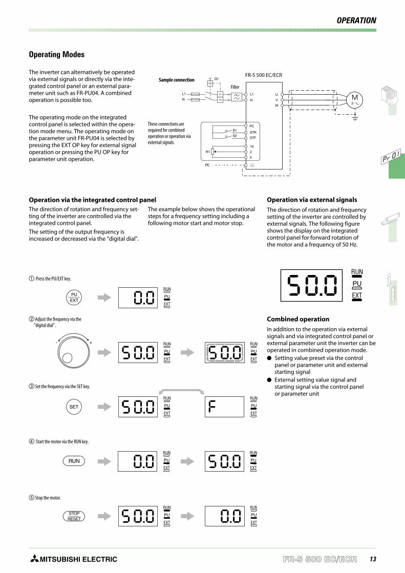
The inverter can alternatively be operatedvia external signals or directly via the inte-grated control panel or an external para-meter unit such as FR-PU04. A combinedoperation is possible too.
The operating mode on the integratedcontrol panel is selected within the opera-tion mode menu. The operating mode onthe parameter unit FR-PU04 is selected bypressing the EXT OP key for external signaloperation or pressing the PU OP key forparameter unit operation.
U
V
W
STR
STF
PC
10
2
5
R1
S1
S2
L1
NI
I
Q1
PE
L1
N
Sample connection
These connections arerequired for combinedoperation or operation viaexternal signals.
Operation via the integrated control panelThe direction of rotation and frequency set-ting of the inverter are controlled via theintegrated control panel.
The setting of the output frequency isincreased or decreased via the "digital dial".
The example below shows the operationalsteps for a frequency setting including afollowing motor start and motor stop.
RUN
PU
EXT
PUEXT
RUN RUN
PU PU
EXT EXT
+-
RUN RUN
PU PU
EXT EXTSET
RUN
PU
EXT
RUN
PU
EXTRUN
RUN
PU
EXT
RUN
PU
EXT
STOPRESET
Press the PU/EXT key.
Adjust the frequency via the"digital dial".
Set the frequency via the SET key.
Stop the motor.
Operation via external signals
The direction of rotation and frequencysetting of the inverter are controlled byexternal signals. The following figureshows the display on the integratedcontrol panel for forward rotation ofthe motor and a frequency of 50 Hz.
Combined operation
In addition to the operation via externalsignals and via integrated control panel orexternal parameter unit the inverter can beoperated in combined operation mode. Setting value preset via the control
panel or parameter unit and externalstarting signal
External setting value signal andstarting signal via the control panelor parameter unit
RUN
PU
EXT
Operating Modes
FR-S 500 EC/ECR
Start the motor via the RUN key.
Filter
14 MITSUBISHI ELECTRICFR-S 500 EC/ECR
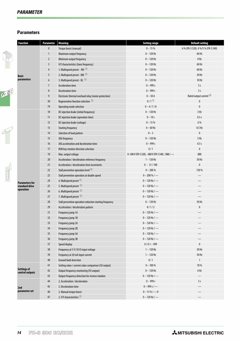
Parameters
Function Parameter Meaning Setting range Default setting
Basicparameters
0 Torque boost (manual) 0 – 15 % 6 % (FR-S 520), 4 %/5 % (FR-S 540)
1 Maximum output frequency 0 – 120 Hz 60 Hz
2 Minimum output frequency 0 – 120 Hz 0 Hz
3 V/f characteristics (base frequency) 0 – 120 Hz 60 Hz
4 1. Multispeed preset - RH 0 – 120 Hz 60 Hz
5 2. Multispeed preset - RM 0 – 120 Hz 30 Hz
6 3. Multispeed preset - RL 0 – 120 Hz 10 Hz
7 Acceleration time 0 – 999 s 5 s
8 Deceleration time 0 – 999 s 5 s
9 Electronic thermal overload relay (motor protection) 0 – 50 A Rated output current
30 Regenerative function selection 0 / 1 0
79 Operating mode selection 0 – 4 / 7 / 8 0
Parameters forstandard driveoperation
10 DC injection brake (initial frequency) 0 – 120 Hz 3 Hz
11 DC injection brake (operation time) 0 – 10 s 0.5 s
12 DC injection brake (voltage) 0 – 15 % 6 %
13 Starting frequency 0 – 60 Hz 0.5 Hz
14 Selection of load pattern 0 – 3 0
15 JOG frequency 0 – 120 Hz 5 Hz
16 JOG acceleration and deceleration time 0 – 999 s 0.5 s
17 RUN key rotation direction selection 0 / 1 0
19 Max. output voltage 0–500 V (FR-S 520), –800 V (FR-S 540) / 888 / — 888
20 Acceleration / deceleration reference frequency 1 – 120 Hz 50 Hz
21 Acceleration / deceleration time increments 0 – 31 / 100 0
22 Stall prevention operation level 0 – 200 % 150 %
23 Stall prevention operation at double speed 0 – 200 % / — —
24 4. Multispeed preset 0 – 120 Hz / — —
25 5. Multispeed preset 0 – 120 Hz / — —
26 6. Multispeed preset 0 – 120 Hz / — —
27 7. Multispeed preset 0 – 120 Hz / — —
28 Stall prevention operation reduction starting frequency 0 – 120 Hz 50 Hz
29 Acceleration / deceleration pattern 0 / 1 / 2 0
31 Frequency jump 1A 0 – 120 Hz / — —
32 Frequency jump 1B 0 – 120 Hz / — —
33 Frequency jump 2A 0 – 120 Hz / — —
34 Frequency jump 2B 0 – 120 Hz / — —
35 Frequency jump 3A 0 – 120 Hz / — —
36 Frequency jump 3B 0 – 120 Hz / — —
37 Speed display 0 / 0.1 – 999 0
38 Frequency at 5 V (10 V) input voltage 1 – 120 Hz 50 Hz
39 Frequency at 20 mA input current 1 – 120 Hz 50 Hz
40 Ground fault detection 0 / 1 1
Settings ofcontrol outputs
41 Setting value / current value comparison (SU output) 0 – 100 % 10 %
42 Output frequency monitoring (FU output) 0 – 120 Hz 6 Hz
43 Output frequency detection for reverse rotation 0 – 120 Hz / — —
2ndparameter set
44 2. Acceleration / deceleration 0 – 999 s 5 s
45 2. Deceleration time 0 – 999 s / — —
46 2. Manual torque boost 0 – 15 % / —0 —
47 2. V/f characteristics 0 – 120 Hz / — —
PARAMETER
15MITSUBISHI ELECTRIC FR-S 500 EC/ECR
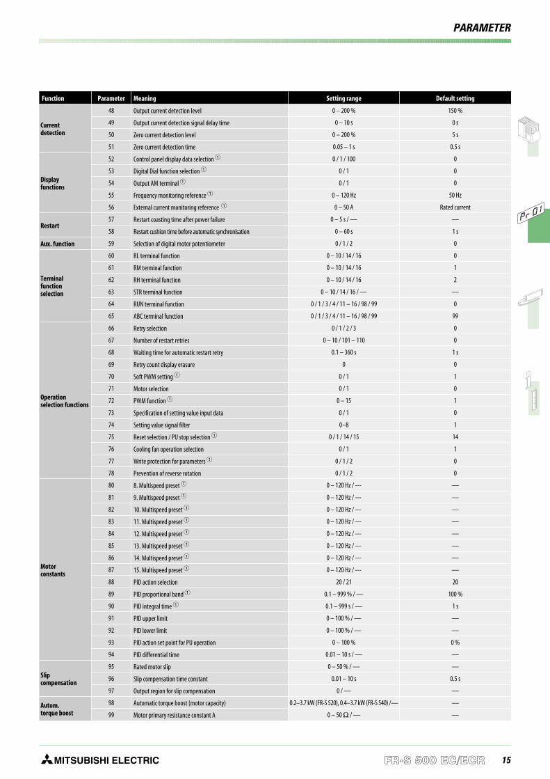
Function Parameter Meaning Setting range Default setting
Currentdetection
48 Output current detection level 0 – 200 % 150 %
49 Output current detection signal delay time 0 – 10 s 0 s
50 Zero current detection level 0 – 200 % 5 s
51 Zero current detection time 0.05 – 1 s 0.5 s
Displayfunctions
52 Control panel display data selection 0 / 1 / 100 0
53 Digital Dial function selection 0 / 1 0
54 Output AM terminal 0 / 1 0
55 Frequency monitoring reference 0 – 120 Hz 50 Hz
56 External current monitoring reference 0 – 50 A Rated current
Restart57 Restart coasting time after power failure 0 – 5 s / — —
58 Restart cushion time before automatic synchronisation 0 – 60 s 1 s
Aux. function 59 Selection of digital motor potentiometer 0 / 1 / 2 0
Terminalfunctionselection
60 RL terminal function 0 – 10 / 14 / 16 0
61 RM terminal function 0 – 10 / 14 / 16 1
62 RH terminal function 0 – 10 / 14 / 16 2
63 STR terminal function 0 – 10 / 14 / 16 / — —
64 RUN terminal function 0 / 1 / 3 / 4 / 11 – 16 / 98 / 99 0
65 ABC terminal function 0 / 1 / 3 / 4 / 11 – 16 / 98 / 99 99
Operationselection functions
66 Retry selection 0 / 1 / 2 / 3 0
67 Number of restart retries 0 – 10 / 101 – 110 0
68 Waiting time for automatic restart retry 0.1 – 360 s 1 s
69 Retry count display erasure 0 0
70 Soft PWM setting 0 / 1 1
71 Motor selection 0 / 1 0
72 PWM function 0 – 15 1
73 Specification of setting value input data 0 / 1 0
74 Setting value signal filter 0–8 1
75 Reset selection / PU stop selection 0 / 1 / 14 / 15 14
76 Cooling fan operation selection 0 / 1 1
77 Write protection for parameters 0 / 1 / 2 0
78 Prevention of reverse rotation 0 / 1 / 2 0
Motorconstants
80 8. Multispeed preset 0 – 120 Hz / --- —
81 9. Multispeed preset 0 – 120 Hz / --- —
82 10. Multispeed preset 0 – 120 Hz / --- —
83 11. Multispeed preset 0 – 120 Hz / --- —
84 12. Multispeed preset 0 – 120 Hz / --- —
85 13. Multispeed preset 0 – 120 Hz / --- —
86 14. Multispeed preset 0 – 120 Hz / --- —
87 15. Multispeed preset 0 – 120 Hz / --- —
88 PID action selection 20 / 21 20
89 PID proportional band 0.1 – 999 % / — 100 %
90 PID integral time 0.1 – 999 s / — 1 s
91 PID upper limit 0 – 100 % / — —
92 PID lower limit 0 – 100 % / — —
93 PID action set point for PU operation 0 – 100 % 0 %
94 PID differential time 0.01 – 10 s / — —
Slipcompensation
95 Rated motor slip 0 – 50 % / — —
96 Slip compensation time constant 0.01 – 10 s 0.5 s
97 Output region for slip compensation 0 / — —
Autom.torque boost
98 Automatic torque boost (motor capacity) 0.2–3.7 kW (FR-S 520), 0.4–3.7 kW (FR-S 540) /— —
99 Motor primary resistance constant A 0 – 50 Ω / — —
PARAMETER
16 MITSUBISHI ELECTRICFR-S 500 EC/ECR
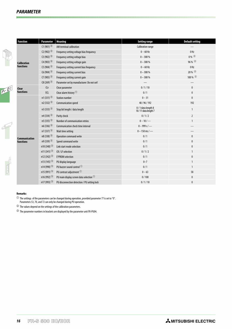
Function Parameter Meaning Setting range Default setting
Calibrationfunctions
C1 (901) AM terminal calibration Calibration range —
C2 (902) Frequency setting voltage bias frequency 0 – 60 Hz 0 Hz
C3 (902) Frequency setting voltage bias 0 – 300 % 0 %
C4 (903) Frequency setting voltage gain 0 – 300 % 96 %
C5 (904) Frequency setting current bias frequency 0 – 60 Hz 0 Hz
C6 (904) Frequency setting current bias 0 – 300 % 20 %
C7 (905) Frequency setting current gain 0 – 300 % 100 %
C8 (269) Parameter set by manufacturer: Do not set! — —
Clearfunctions
CLr Clear parameter 0 / 1 / 10 0
ECL Clear alarm history 0 / 1 0
Communicationfunctions
n1 (331) Station number 0 – 31 0
n2 (332) Communication speed 48 / 96 / 192 192
n3 (333) Stop bit length / data length 0 / 1 data length 810 / 11 data length 7 1
n4 (334) Parity check 0 / 1 / 2 2
n5 (335) Number of communication retries 0 – 10 / — 1
n6 (336) Communication check time interval 0 – 999 s / — —
n7 (337) Wait time setting 0 – 150 ms / — —
n8 (338) Operation command write 0 / 1 0
n9 (339) Speed command write 0 / 1 0
n10 (340) Link start mode selection 0 / 1 0
n11 (341) CR / LF selection 0 / 1 / 2 1
n12 (342) E²PROM selection 0 / 1 0
n13 (145) PU display language 0–7 1
n14 (990) PU buzzer sound control 0 / 1 1
n15 (991) PU contrast adjustment 0 – 63 58
n16 (992) PU main display screen data selection 0 / 100 0
n17 (993) PU disconnection detection / PU setting lock 0 / 1 / 10 0
Remarks: The settings of the parameters can be changed during operation, provided parameter 77 is set to “0”.
Parameters 53, 70, and 72 can only be changed during PU operation. The values depend on the settings of the calibration parameters. The parameter numbers in brackets are displayed by the parameter unit FR-PU04.
PARAMETER
17MITSUBISHI ELECTRIC FR-S 500 EC/ECR
PROTECTIVE FUNCTIONS
Display Meaning Description Remedy
OC1 Overcurrent 1(acceleration)
A) The output current of the inverter has reached or exceeded 200 % of the rated currentduring acceleration, deceleration, or at constant speed.
B) The temperature of the main circuits of the inverter rises rapidly.
The cause for the activation of the protectivefunction is a short circuit or a ground fault acrossthe main outputs, an exceeding moment of inertiaof the load (GD2), too short acceleration / decele-ration time presets, restart during a motor idlingphase, operation of a motor with an exceedingcapacity.
Overheating due to insufficient cooling (defectivecooling fan or choked heat sink).
OC2 Overcurrent 2(constant speed)
OC3 Overcurrent 3(deceleration)
OV1 Overvoltage 1(acceleration)
The converter voltage has increased highly due to regenerative energy. The overvoltage limitwas exceeded during acceleration, deceleration, or at constant speed.
In most cases the protective function is activateddue to a too short deceleration time preset or aregenerative overload.
Increase the deceleration time by connectingan external brake unit.
An overvoltage in the mains power supplyactivates this protective function as well.
OV2 Overvoltage 2(constant speed)
OV3 Overvoltage 3(deceleration)
THN Overload(motor)
The electronic overload protection for the motor or inverter was activated.
The electronic motor protection switch continually detects the motor current and the output fre-quency of the inverter. If a self-cooling motor operates over a long period at low speed but hightorque, the motor is thermally overloaded and the protective function is activated.
If several motors are operated by one inverter the motor protection switch will not operate properly. Inthis case deactivate the motor protection and replace it by external protection switches.
Decrease the motor load to avoid an activation.
Check whether the performance range of themotor and inverter correspond.THT Overload
(inverter)
FIn Fin overheat If the cooling fin overheats, the fin overheat sensor activates and halts inverter output. Check ambient temperature.
Fn Fan breakdown The cooling fan breaks down or an operation different from the setting of parameter 76is performed. Replace cooling fan. Check Parameter 76.
GF Ground fault An overcurrent occured due to a ground fault upon the inverter output (load side). Check load connections (motor circuit).
0HTActivation of an externalmotor protection relay(thermal contact)
An external motor protective switch was activated.If an external motor protective switch for thermal monitoring is used, this switch can activatethe protective function of the inverter.
Check motor load and drive.
0LT Stall preventionoverload A long lasting excess of the current limit (OL display) shuts down the inverter.
Reduce the load.Check the preset values for the current limit(parameter 22) and the stall prevention selection(parameter 21).
OPT Communication error The protective function is activated, if a setting or connection error occurs during serialcommunication.
Check connections and connectors of theoptional unit.
PE Memory error Error on access of the data memory of the inverter.Please contact your nearest MITSUBISHIELECTRIC representative if the error occursagain.
PUE Parameter unit connectionerror
A connection error between inverter and external parameter unit occurred during operation.This alarm is only returned, if parameter 17 is set to "1". Check the connection of the parameter unit.
rET Automatic restart retryexceeded
After activation of a protective function the inverter failed to be restarted automaticallywithin the number of retries specified in parameter 67.
Remedy the actual cause of the originaryprotective function.
CPU CPU error Scan time of CPU was exceeded. Failure on CPU printed circuit board.Restart the inverter.Contact the MITSUBISHI ELECTRIC customerservice if the error occurs again.
PS Inverter was stopped viacontrol panel or PU STOP key on the control panel or PU was pressed during external operating mode. Check parameter 75.
OL
Overcurrent duringacceleration
If a current of more than 150 % of the rated inverter current flows in the motor, this functionstops the increase of the frequency until the overload current reduces to prevent the inverterfrom resulting in overcurrent shut-off. When the overload current has reduced below 150 %, thisfunction increases the frequency again.
Change the acceleration/deceleration time.Increase the stall prevention operation level viaparameter 22. Disable the stall prevention viaparameter 21. Check whether the torque boostin parameter 0 is set higher than required.
Overcurrent duringconstant speed
If a current of more than 150 % of the rated inverter current flows in the motor, this functionlowers the frequency until the overload current reduces to prevent the inverter from resulting inovercurrent shut-off. When the overload current has reduced below 150 %, this function increa-ses the frequency up to the set value.
Overcurrent duringdeceleration
If a current of more than 150 % of the rated inverter current flows in the motor, this functionstops the decrease of the frequency until the overload current reduces to prevent theinverter from resulting in overcurrent shut-off. When the overload current has reduced below150 %, this function decreases the frequency again.
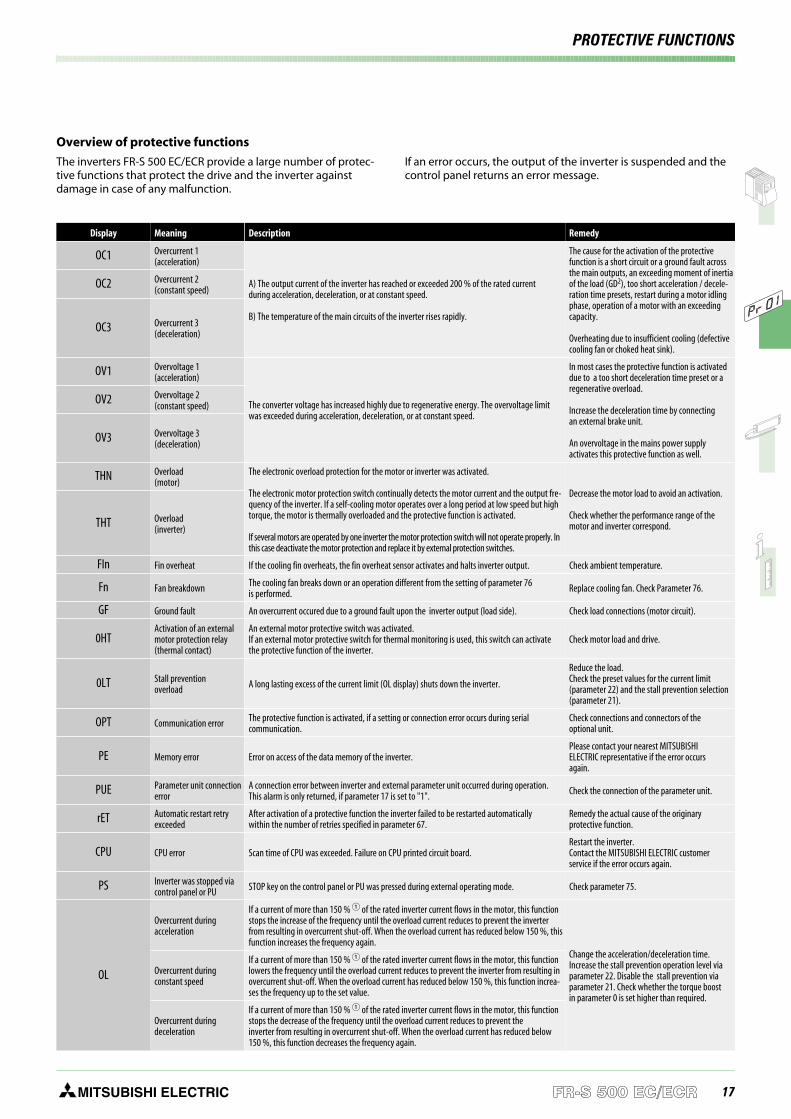
Overview of protective functions
The inverters FR-S 500 EC/ECR provide a large number of protec-tive functions that protect the drive and the inverter againstdamage in case of any malfunction.
If an error occurs, the output of the inverter is suspended and thecontrol panel returns an error message.
18 MITSUBISHI ELECTRICFR-S 500 EC/ECR
PROTECTIVE FUNCTIONS
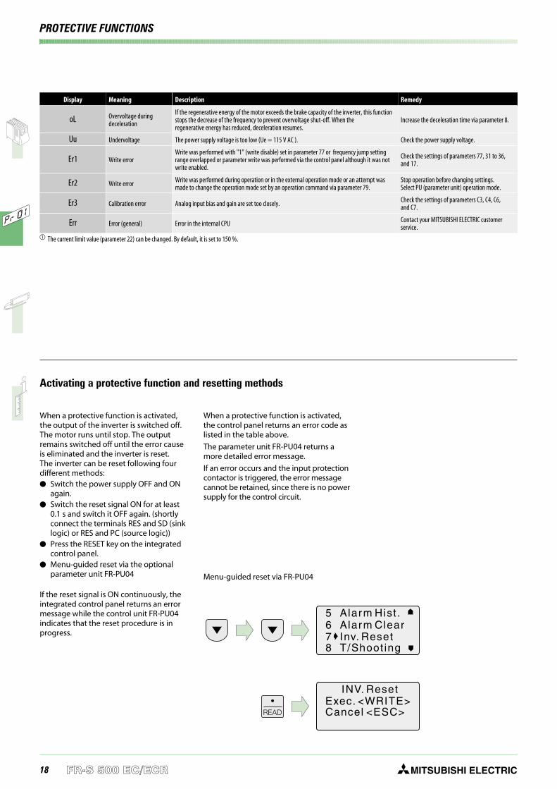
When a protective function is activated,the output of the inverter is switched off.The motor runs until stop. The outputremains switched off until the error causeis eliminated and the inverter is reset.The inverter can be reset following fourdifferent methods: Switch the power supply OFF and ON
again. Switch the reset signal ON for at least
0.1 s and switch it OFF again. (shortlyconnect the terminals RES and SD (sinklogic) or RES and PC (source logic))
Press the RESET key on the integratedcontrol panel.
Menu-guided reset via the optionalparameter unit FR-PU04
If the reset signal is ON continuously, theintegrated control panel returns an errormessage while the control unit FR-PU04indicates that the reset procedure is inprogress.
When a protective function is activated,the control panel returns an error code aslisted in the table above.
The parameter unit FR-PU04 returns amore detailed error message.
If an error occurs and the input protectioncontactor is triggered, the error messagecannot be retained, since there is no powersupply for the control circuit.
Activating a protective function and resetting methods
Display Meaning Description Remedy
oL Overvoltage duringdeceleration
If the regenerative energy of the motor exceeds the brake capacity of the inverter, this functionstops the decrease of the frequency to prevent overvoltage shut-off. When theregenerative energy has reduced, deceleration resumes.
Increase the deceleration time via parameter 8.
Uu Undervoltage The power supply voltage is too low (Ue = 115 V AC ). Check the power supply voltage.
Er1 Write errorWrite was performed with "1" (write disable) set in parameter 77 or frequency jump settingrange overlapped or parameter write was performed via the control panel although it was notwrite enabled.
Check the settings of parameters 77, 31 to 36,and 17.
Er2 Write error Write was performed during operation or in the external operation mode or an attempt wasmade to change the operation mode set by an operation command via parameter 79.
Stop operation before changing settings.Select PU (parameter unit) operation mode.
Er3 Calibration error Analog input bias and gain are set too closely. Check the settings of parameters C3, C4, C6,and C7.
Err Error (general) Error in the internal CPU Contact your MITSUBISHI ELECTRIC customerservice.
The current limit value (parameter 22) can be changed. By default, it is set to 150 %.
Menu-guided reset via FR-PU04
READ
INV. ResetExec. <WRITE>Cancel <ESC>
5 Alarm Hist .6 Alarm Clear7 Inv. Reset8 T/Shoot ing
19MITSUBISHI ELECTRIC FR-S 500 EC/ECR
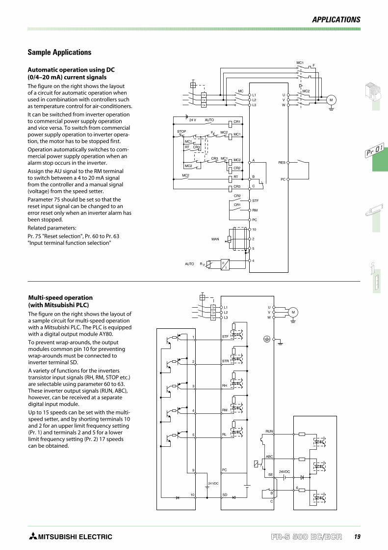
Sample Applications
Multi-speed operation(with Mitsubishi PLC)The figure on the right shows the layout ofa sample circuit for multi-speed operationwith a Mitsubishi PLC. The PLC is equippedwith a digital output module AY80.
To prevent wrap-arounds, the outputmodules common pin 10 for preventingwrap-arounds must be connected toinverter terminal SD.
A variety of functions for the inverterstransistor input signals (RH, RM, STOP etc.)are selectable using parameter 60 to 63.These inverter output signals (RUN, ABC),however, can be received at a separatedigital input module.
Up to 15 speeds can be set with the multi-speed setter, and by shorting terminals 10and 2 for an upper limit frequency setting(Pr. 1) and terminals 2 and 5 for a lowerlimit frequency setting (Pr. 2) 17 speedscan be obtained.
Automatic operation using DC(0/4–20 mA) current signalsThe figure on the right shows the layoutof a circuit for automatic operation whenused in combination with controllers suchas temperature control for air-conditioners.
It can be switched from inverter operationto commercial power supply operationand vice versa. To switch from commercialpower supply operation to inverter opera-tion, the motor has to be stopped first.
Operation automatically switches to com-mercial power supply operation when analarm stop occurs in the inverter.
Assign the AU signal to the RM terminalto switch between a 4 to 20 mA signalfrom the controller and a manual signal(voltage) from the speed setter.
Parameter 75 should be set so that thereset input signal can be changed to anerror reset only when an inverter alarm hasbeen stopped.
Related parameters:
Pr. 75 "Reset selection", Pr. 60 to Pr. 63"Input terminal function selection"
L1MC MC2
MC1
A
B
10
4
STF
RM
PC
C
2
5
R ϑ
CR1
RT
CR3
MC1
MC1 MC2
CR2
CR2
CR1
MAN
MC2
MC1
MC2
MC2
STOP
24 V
RT CR3
CR3
F
F
AUTO
AUTO
L2
L3
I
I
I
M
U
V
W
PC
RES
ϑI
1 STF
STR
RH
RM
RL
6
RUN
ABC
SE
B
C
24VDCPC
SD
2
3
4
5
9
10
24 VDC
L1
L2
L3
I
I
MU
V
WI
APPLICATIONS

20 MITSUBISHI ELECTRICFR-S 500 EC/ECR
OPTIONS
External optionsBesides the parameter unit FR-PU04 thatprovides an interactive control of theinverter the external options include noise
filters complying with the EMC directives,filters improving the efficiency as well asbrake units and brake resistors.
Option Type Description Remarks / specifications Art. no.
Externaloptions
Parameter unit (8 languages) FR-PU04 Interactive parameter unit with LC display For details refer to p.13. 67735
Connection cable for theparameter unit
FR-A5 CBL Cable for a remote connection of the parameter unit FR-PU04. Available length: 1; 2.5 and 5 m1 m: 70727
2.5 m: 707285 m: 70729
Interface cable SC-FR PC Communications cable for RS232 or RS485 interface to connect anexternal personal computer
Length 3 m; can be used for examplewith the VFD Setup Software(only with ECR version)
88426
VFD Setup Software FR-SW0-SETUP-W Parameter and setup software for theFR-S 500, FR-E 500, FR-F500 and FR-A 500 series inverters English / German 149718
EMCnoisefilter
FR-S 520S-0.2 – 0.75kEC/ECR
FR-S5NFSA-0.75 k,FR-S5NFSB-0.75 k
FFR-S520S-14A-RF1 Noise filter for the FR-S 520 seriesfor compliance with EMC directives For details refer to p. 21 see p. 21
FR-S 520S-1.5kEC/ECR
FR-S5NFSA-1.5 k,FR-S5NFSB-1.5 k
FFR-S520S-20A-RF1
FR-S 540-0.4 – 1.5 kEC/ECR
FFR-S540-8A-RF100Noise filter for the FR-S 540 seriesfor compliance with EMC directives For details refer to p. 21
138425
FR-S 540-2.2 – 3.7 kEC/ECR
FFR-S540-13A-RF100 138423
Brakeunit
FR-S 520 S EC/ECR BU-UFS-22J For improving the brake capacity. For loads with high moment ofinertia or negative loads. Used in combination with a resistor unit. For details refer to p. 21
127962
FR-S 540 EC/ECR BU-UFS-22 127947
DIN rail mounting set
FR-UDA 01 Adapter for mounting frequency invertersup to 0.75 k on a DIN rail When using the DIN rail adapter, filters
can not be footprint mounted
130833
FR-UDA 02 Adapter for mounting frequency invertersfrom 1.5 k on a DIN rail
130832
! L1 N1 PE! L1 N1 PE
RUN
RUN
SETMODE
PU
EXT
PUEXT
STOP
RESET
MITSUBISHIFR-S500
RUN
RUN
SETMODE
PU
EXT
PUEXT
STOP
RESET
MITSUBISHIFR-S500
Mounting the FR-S 520 ECon a DIN rail using themounting set FR-UDA 01
Installing an EMCnoise filter on anFR-S 520 EC
Options
21MITSUBISHI ELECTRIC FR-S 500 EC/ECR
OPTIONS
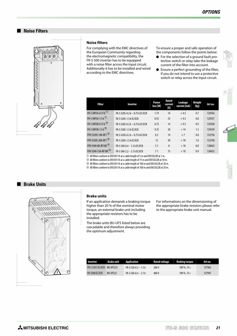
Noise Filters
Noise filtersFor complying with the EMC directives ofthe European Community regardingthe electromagnetic compatibility, theFR-S 500 inverter has to be equippedwith a noise filter across the input circuit.Additionally it has to be installed and wiredaccording to the EMC directives.
To ensure a proper and safe operation ofthe components follow the points below: For the selection of a ground fault pro-
tective switch or relay take the leakagecurrent of the filter into account.
Ensure a perfect grounding of the filter,if you do not intend to use a protectiveswitch or relay across the input circuit.
! L1 N1 PE
Brake Units
Brake unitsIf an application demands a braking torquehigher than 20 % of the nominal motortorque, an external brake unit includingthe appropriate resistors has to beinstalled.
The brake units BU-UFS listed below arecascadable and therefore always providingthe optimum adjustment.
For informations on the dimensioning ofthe appropriate brake resistors please referto the appropriate brake unit manual.
Inverter Brake unit Application Rated voltage Braking torque Art no.
FR-S 520 S EC/ECR BU-UFS22J FR-S 520-0.2 – 1.5 k 200 V 100 %, 15 s 127962
FR-S540 EC/ECR BU-UFS22 FR-S 540-0.4 – 3.7 k 400 V 100 %, 15 s 127947
Filter InverterPower
loss [W]
Ratedcurrent
[A]
Leakagecurrent [mA]
Weight[kg]
Art no.
FR-S 5NFSA-0.75 k FR-S 520S-0.2 k – 0.75 k EC/ECR 1.74 14 < 4.5 0.7 129356
FR-S 5NFSA-1.5 k FR-S 520S-1.5 k EC/ECR 8.55 25 < 9.5 0.8 129357
FR-S 5NFSB-0.75 k FR-S 520S-0.2 k – 0.75 k EC/ECR 6.75 14 < 9.5 0.9 129358
FR-S 5NFSB-1.5 k FR-S 520S-1.5 k EC/ECR 9.25 20 < 14 1.3 129359
FFR-S520S-14A-RF1 FR-S 520S-0.2 k – 0.75 k EC/ECR 6.5 14 < 7 0.8 152736
FFR-S520S-20A-RF1 FR-S 520S-1.5 k EC/ECR 12 20 < 10 1.0 152740
FFR-S540-8A-RF100 FR-S 540-0.4 – 1.5 k EC/ECR 5.1 8 < 10 0.8 138425
FFR-S540-13A-RF100 FR-S 540-2.2 – 3.7 k EC/ECR 7.1 13 < 10 0.9 138423
All filters conform to EN55011A at a cable length of 5 m and EN55022B at 1 m. All filters conform to EN55011A at a cable length of 75 m and EN55022B at 30 m. All filters conform to EN55011A at a cable length of 100 m and EN55022B at 30 m. All filters conform to EN55011A at a cable length of 100 m and EN55022B at 20 m.
22 MITSUBISHI ELECTRICFR-S 500 EC/ECR
DIMENSIONS
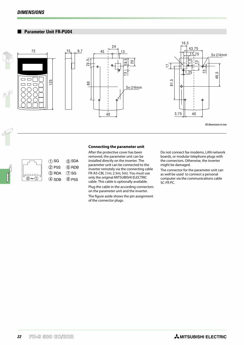
Parameter Unit FR-PU04
5x 4mm∅
16,5
1,25
43,7511,75
403,75
5x 4mm∅
1781
,5
46,515
131,5
40
2445 13
20
8021
,5
18,5
13
72 15 9,712
5
All dimensions in mm
1 5SG SDA
2 6P5S RDB
3 7RDA SG
4 8SDB P5S
~
Connecting the parameter unitAfter the protective cover has beenremoved, the parameter unit can beinstalled directly on the inverter. Theparameter unit can be connected to theinverter remotely via the connecting cableFR-A5-CBL (1m; 2.5m; 5m). You must useonly the original MITSUBISHI ELECTRICcable. This cable is optionally available.
Plug the cable in the according connectorson the parameter unit and the inverter.
The figure aside shows the pin assignmentof the connector plugs.
Do not connect fax modems, LAN networkboards, or modular telephone plugs withthe connectors. Otherwise, the invertermight be damaged.
The connector for the parameter unit canas well be used to connect a personalcomputer via the communications cableSC-FR PC.
23MITSUBISHI ELECTRIC FR-S 500 EC/ECR
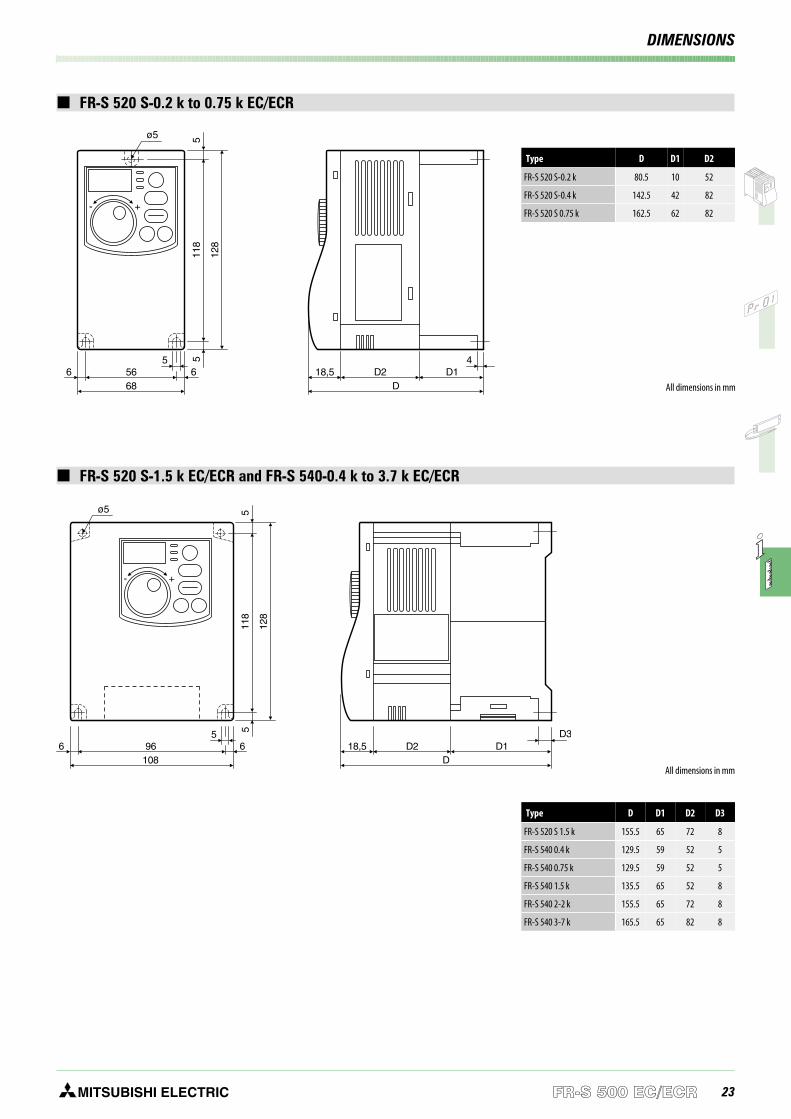
FR-S 520 S-0.2 k to 0.75 k EC/ECR
FR-S 520 S-1.5 k EC/ECR and FR-S 540-0.4 k to 3.7 k EC/ECR
+-11
85
5
128
ø5
5 466 56 D218,5 D1
68 D
+-
118
55
128
ø5
5 D366 96 D218,5 D1
108 D
All dimensions in mm
All dimensions in mm
Type D D1 D2
FR-S 520 S-0.2 k 80.5 10 52
FR-S 520 S-0.4 k 142.5 42 82
FR-S 520 S 0.75 k 162.5 62 82
DIMENSIONS
Type D D1 D2 D3
FR-S 520 S 1.5 k 155.5 65 72 8
FR-S 540 0.4 k 129.5 59 52 5
FR-S 540 0.75 k 129.5 59 52 5
FR-S 540 1.5 k 135.5 65 52 8
FR-S 540 2-2 k 155.5 65 72 8
FR-S 540 3-7 k 165.5 65 82 8
24 MITSUBISHI ELECTRICFR-S 500 EC/ECR
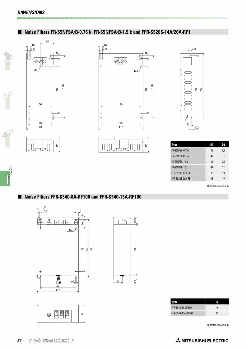
Noise Filters FR-S5NFSA/B-0.75 k, FR-S5NFSA/B-1.5 k and FFR-S520S-14A/20A-RF1
118
D1
8
35
4,5
10
56
M4
56
70
158
118
D1
158
168
8
4,5 4,5
5
D2
10
96
M4
96
110
158
All dimensions in mm
DIMENSIONS
Noise Filters FFR-S540-8A-RF100 and FFR-S540-13A-RF100
118
139
19,5
9,5
306
158
168
74,510
D
M4
ø5 25
96
112
All dimensions in mm
Type D
FFR-S540-8A-RF100 40
FFR-S540-13A-RF100 45
Type D1 D2
FR-S5NFSA-0.75k 35 9,5
FR-S5NFSB-0.75k 47 11
FR-S5NFSA-1.5k 35 9,5
FR-S5NFSB-1.5k 47 11
FFR-S520S-14A-RF1 38 19
FFR-S520S-20A-RF1 38 19
25MITSUBISHI ELECTRIC FR-S 500 EC/ECR
DIMENSIONS
15 67
3 x M4x0,7
68
128
8,7
67
4 x M4x0,7
108
128
8,7
15
10
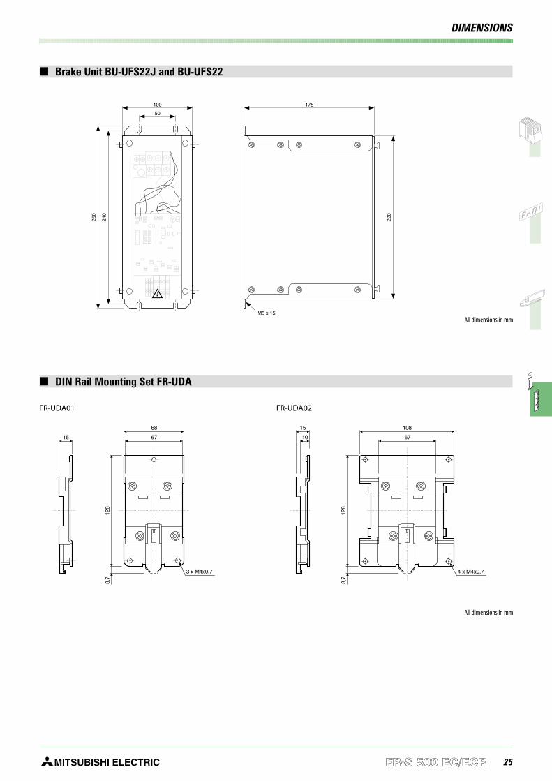
DIN Rail Mounting Set FR-UDA
FR-UDA01 FR-UDA02
All dimensions in mm
Brake Unit BU-UFS22J and BU-UFS22
50
M5 x 15
240
220
250
100 175
All dimensions in mm
26 MITSUBISHI ELECTRIC
Company: . . . . . . . . . . . . . . . . . . . . .
Department: . . . . . . . . . . . . . . . . . . . . .
Street: . . . . . . . . . . . . . . . . . . . . .
Address: . . . . . . . . . . . . . . . . . . . . .
Phone: . . . . . . . . . . . . . . . . . . . . .
Fax: . . . . . . . . . . . . . . . . . . . . .
Order declaration
Pos. Number Item (type) Article number Description Remarks
MITSUBISHI ELECTRIC EUROPE B.V.
Industrial Automation / German Branch
Gothaer-Str. 8
D-40880 Ratingen
Fax: +49 2102 486-7170
Notes when ordering:
When ordering, please use only the type designations and order numbers shown in this catalogue.
ORDER FORM
27FR-S 500 EC/ECR
INDEX
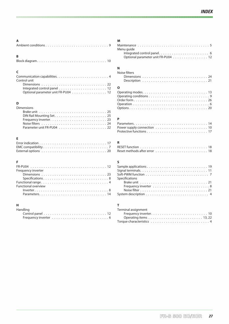
AAmbient conditions . . . . . . . . . . . . . . . . . . . . . . . . . . . . . 9
BBlock diagram . . . . . . . . . . . . . . . . . . . . . . . . . . . . . . . . 10
CCommunication capabilities. . . . . . . . . . . . . . . . . . . . . . . . 4Control unit
Dimensions . . . . . . . . . . . . . . . . . . . . . . . . . . . . . . 22Integrated control panel . . . . . . . . . . . . . . . . . . . . . . 12Optional parameter unit FR-PU04 . . . . . . . . . . . . . . . . 12
DDimensions
Brake unit . . . . . . . . . . . . . . . . . . . . . . . . . . . . . . . 25DIN Rail Mounting Set . . . . . . . . . . . . . . . . . . . . . . . . 25Frequency inverter . . . . . . . . . . . . . . . . . . . . . . . . . . 23Noise filters . . . . . . . . . . . . . . . . . . . . . . . . . . . . . . 24Parameter unit FR-PU04 . . . . . . . . . . . . . . . . . . . . . . 22
EError indication . . . . . . . . . . . . . . . . . . . . . . . . . . . . . . . 17EMC compatibility . . . . . . . . . . . . . . . . . . . . . . . . . . . . . . 7External options . . . . . . . . . . . . . . . . . . . . . . . . . . . . . . 20
FFR-PU04 . . . . . . . . . . . . . . . . . . . . . . . . . . . . . . . . . . . 12Frequency inverter
Dimensions . . . . . . . . . . . . . . . . . . . . . . . . . . . . . . 23Specifications . . . . . . . . . . . . . . . . . . . . . . . . . . . . . . 8
Functional range . . . . . . . . . . . . . . . . . . . . . . . . . . . . . . . 4Functional overview
Inverter . . . . . . . . . . . . . . . . . . . . . . . . . . . . . . . . . . 8Parameters. . . . . . . . . . . . . . . . . . . . . . . . . . . . . . . 14
HHandling
Control panel . . . . . . . . . . . . . . . . . . . . . . . . . . . . . 12Frequency inverter . . . . . . . . . . . . . . . . . . . . . . . . . . 6
MMaintenance . . . . . . . . . . . . . . . . . . . . . . . . . . . . . . . . . 5Menu guide
Integrated control panel. . . . . . . . . . . . . . . . . . . . . . . 6Optional parameter unit FR-PU04 . . . . . . . . . . . . . . . . 12
NNoise filters
Dimensions . . . . . . . . . . . . . . . . . . . . . . . . . . . . . . 24Description . . . . . . . . . . . . . . . . . . . . . . . . . . . . . . 21
OOperating modes. . . . . . . . . . . . . . . . . . . . . . . . . . . . . . 13Operating conditions . . . . . . . . . . . . . . . . . . . . . . . . . . . . 9Order form . . . . . . . . . . . . . . . . . . . . . . . . . . . . . . . . . . 26Operation . . . . . . . . . . . . . . . . . . . . . . . . . . . . . . . . . . . 6Options . . . . . . . . . . . . . . . . . . . . . . . . . . . . . . . . . . . . 20
PParameters. . . . . . . . . . . . . . . . . . . . . . . . . . . . . . . . . . 14Power supply connection . . . . . . . . . . . . . . . . . . . . . . . . 10Protective functions . . . . . . . . . . . . . . . . . . . . . . . . . . . . 17
RRESET function . . . . . . . . . . . . . . . . . . . . . . . . . . . . . . . 18Reset methods after error . . . . . . . . . . . . . . . . . . . . . . . . 18
SSample applications . . . . . . . . . . . . . . . . . . . . . . . . . . . . 19Signal terminals. . . . . . . . . . . . . . . . . . . . . . . . . . . . . . . 11Soft-PWM function . . . . . . . . . . . . . . . . . . . . . . . . . . . . . 7Specifications
Brake unit . . . . . . . . . . . . . . . . . . . . . . . . . . . . . . . 21Frequency inverter . . . . . . . . . . . . . . . . . . . . . . . . . . 8Noise filter . . . . . . . . . . . . . . . . . . . . . . . . . . . . . . . 21
System description . . . . . . . . . . . . . . . . . . . . . . . . . . . . . 4
TTerminal assignment
Frequency inverter . . . . . . . . . . . . . . . . . . . . . . . . . . 10Operating items . . . . . . . . . . . . . . . . . . . . . . . . . 13, 22
Torque characteristics . . . . . . . . . . . . . . . . . . . . . . . . . . . 4
MITSUBISHI ELECTRICSpecifications subject to change without notice.Art. no. 132467-E, Printed in Germany 01.04
INDUSTRIAL AUTOMATION
Gothaer Strasse 8 Phone: +49 2102 486-0 Fax: +49 2102 486-7170 www.mitsubishi-automation.deD-40880 Ratingen Hotline: +49 1805 000-7650 [email protected] www.mitsubishi-automation.com
HEADQUARTERS
MITSUBISHI ELECTRIC EUROPEEUROPE B.V.German BranchGothaer Straße 8D-40880 RatingenPhone: +49 (0) 21 02 / 486-0Fax: +49 (0) 21 02 / 4 86-11 20e mail: [email protected] ELECTRIC FRANCEEUROPE B.V.French Branch25, Boulevard des BouvetsF-92741 Nanterre CedexPhone: +33 1 55 68 55 68Fax: +33 1 55 68 56 85e mail: [email protected] ELECTRIC . ITALYEUROPE B.VItalian BranchVia Paracelso 12I-20041 Agrate Brianza (MI)Phone: +39 039 / 60 53 1Fax: +39 039 / 60 53 312e mail: [email protected] ELECTRIC SPAINEUROPE B.V.Spanish BranchCarretera de Rubí 76-80E-08190 Sant Cugat del VallésPhone: +34 9 3 / 565 3131Fax: +34 9 3 / 589 2948e mail: [email protected] ELECTRIC UKEUROPE B.V.UK BranchTravellers LaneGB-Hatfield Herts. AL10 8 XBPhone: +44 (0) 1707 / 27 61 00Fax: +44 (0) 1707 / 27 86 95MITSUBISHI ELECTRIC JAPANCORPORATIONOffice Tower “Z” 14 F8-12,1 chome, Harumi Chuo-KuTokyo 104-6212Phone: +81 3 / 622 160 60Fax: +81 3 / 622 160 75MITSUBISHI ELECTRIC USAAUTOMATION500 Corporate Woods ParkwayVernon Hills, IL 60061Phone: +1 847 / 478 21 00Fax: +1 847 / 478 22 83
EUROPEAN REPRESENTATIVES
GEVA AUSTRIAWiener Straße 89A-2500 BadenPhone: +43 (0)2252 / 85 55 20Fax: +43 (0)2252 / 488 60e mail: [email protected] BELARUSOktjabrskaya 16/5, Ap 704BY-220030 MinskPhone: +375 (0)17 / 2104626Fax: +375 (0)17 / 2275830e mail: [email protected] b.v. BELGIUMControl SystemsPontbeeklaan 43B-1731 Asse-ZellikPhone: +32 (0)2 / 467 17 51Fax: +32 (0)2 / 467 17 45e mail: [email protected] CO. BULGARIA4, A. Ljapchev Blvd.BG-1756 SofiaPhone: +359 (0)2 / 97 44 058Fax: +359 (0)2 / 97 44 061e mail: —INEA CR d.o.o. CROATIADrvinje 63HR-10000 ZagrebPhone: +385 (0)1 / 3667140Fax: +385 (0)1 / 3667140e mail: —AutoCont CZECH REPUBLICControl Systems s.r.o.Nemocnicni 12CZ-70200 Ostrava 2Phone: +420 59 / 6152 111Fax: +420 59 / 6152 562e mail: [email protected] poulsen DENMARKindustri & automationGeminivej 32DK-2670 GrevePhone: +45 (0)43 / 95 95 95Fax: +45 (0)43 / 95 95 91e mail: [email protected] Elektrotehnika AS ESTONIAPärnu mnt.160iEE-10621 TallinnPhone: +372 6 / 51 72 80Fax: +372 6 / 51 72 88e mail: [email protected] POWEL OY FINLANDBox 236FIN-28101 PoriPhone: +358 (0)2 / 550 800Fax: +358 (0)2 / 550 8841e mail: [email protected] A.B.E.E. GREECE5, Mavrogenous Str.GR-18542 PiraeusPhone: +302 (0)10 / 42 10 050Fax: +302 (0)10 / 42 12 033e mail: [email protected] Automatika Kft. HUNGARY55, Harmat St.HU-1105 BudapestPhone: +36 (0)1 / 2605 602Fax: +36 (0)1 / 2605 602e mail: [email protected] POWEL LATVIALienes iela 28LV-1009 RigaPhone: +371 784 2280Fax: +371 784 2281e mail: [email protected]
EUROPEAN REPRESENTATIVES
UAB UTU POWEL LITHUANIASavanoriu Pr. 187LT-2053 VilniusPhone: +370 (0)52323-101Fax: +370 (0)52322-980e mail: [email protected] Srl MOLDOVACuza-Voda 36/1-81MD-2061 ChisinauPhone: +373 (0)2 / 562 263Fax: +373 (0)2 / 562 263e mail: [email protected] b.v. NETHERLANDSControl SystemsDonauweg 2 BNL-1043 AJ AmsterdamPhone: +31 (0)20 / 587 6700Fax: +31 (0)20 / 587 6839e mail: [email protected] Control NETHERLANDSAutomation b.v.Markenweg 5NL-7051 HS VarsseveldPhone: +31 (0)315 / 257 260Fax: +31 (0)315 / 257 269e mail: —Beijer Electronics AS NORWAYTeglverksveien 1N-3002 DrammenPhone: +47 (0)32 / 24 30 00Fax: +47 (0)32 / 84 85 77e mail: [email protected] Technology Sp. z o.o. POLANDul. Sliczna 36PL-31-444 KrakówPhone: +48 (0)12 / 632 28 85Fax: +48 (0)12 / 632 47 82e mail: [email protected] Trading & Services srl ROMANIAStr. Biharia Nr. 67-77RO-013981 Bucuresti 1Phone: +40 (0) 21 / 201 1146Fax: +40 (0) 21 / 201 1148e mail: [email protected] Autocomp a.s. SLOVAKIAChalupkova 7SK-81109 BratislavaPhone: +421 (0)7 592 22 54Fax: +421 (0)7 592 22 48e mail: [email protected] d.o.o. SLOVENIAStegne 11SI-1000 LjubljanaPhone: +386 (0)1 513 8100Fax: +386 (0)1 513 8170e mail: [email protected] Electronics AB SWEDENBox 426S-20124 MalmöPhone: +46 (0)40 / 35 86 00Fax: +46 (0)40 / 35 86 02e mail: [email protected] AG SWITZERLANDPostfach 282CH-8309 NürensdorfPhone: +41 (0) 1 / 838 48 11Fax: +41 (0) 1 / 838 48 12e mail: [email protected]
EUROPEAN REPRESENTATIVES
GTS TURKEYDarülaceze Cad. No. 43A KAT: 2TR-80270 Okmeydani-IstanbulPhone: +90 (0) 212 / 320 1640Fax: +90 (0) 212 / 320 1649e mail: [email protected] Automation UKRAINE15, M. Raskovoyi St., Floor 10,Office 1010U-02002 KievPhone: +380 (0) 44 / 238 83 16Fax: +380 (0) 44 / 238 83 17e mail: [email protected]
EURASIAN REPRESENTATIVES
CONSYS RUSSIAPromyshlennaya St. 42RU-198099 St PetersburgPhone: +7 812 / 325 36 53Fax: +7 812 / 325 36 53e mail: [email protected] RUSSIAul. Garschina 11RU-140070 Moscow OblastPhone: +7 095/ 557 9756Fax: +7 095/ 746 8880e mail: [email protected] RUSSIAKrasnij Prospekt 220-1, Office 312RU-630049 NovosibirskPhone: +7 3832 / 10 66 18Fax: +7 3832 / 10 66 26e mail: [email protected] RUSSIARyazanskij Prospekt, 8A, Office 100RU-109428 MoscowPhone: +7 095 / 232 0207Fax: +7 095 / 232 0327e mail: [email protected] RUSSIAPolzunova 7RU-630051 NovosibirskPhone: +7 095 / 416 4321Fax: +7 095 / 416 4321e mail: [email protected] Rosgidromontazh Ltd RUSSIA23, Lesoparkovaya Str.RU-344041 Rostov On DonPhone: +7 8632 / 36 00 22Fax: +7 8632 / 36 00 26e mail: —STC Drive Technique RUSSIAPoslannikov per., 9, str.1RU-107005 MoscowPhone: +7 095 / 786 21 00Fax: +7 095 / 786 21 01e mail: [email protected]
MIDDLE EAST REPRESENTATIVE
SHERF Motion Techn. LTD ISRAELRehov Hamerkava 19IL-58851 HolonPhone: +972 (0) 3 / 559 54 62Fax: +972 (0) 3 / 556 01 82e mail: —
AFRICAN REPRESENTATIVE
CBI Ltd SOUTH AFRICAPrivate Bag 2016ZA-1600 IsandoPhone: +27 (0) 11 / 928 2000Fax: +27 (0) 11 / 392 2354e mail: [email protected]


![[3] [4,5]. - chronos.msu.ru](https://img.pdfslide.us/doc/110x75/61a4f7a2b980bb7e291aaae4/3-45-.jpg)