Embed Size (px)
Citation preview

Disclaimer:
The information contained herein is for general information purposes only. Users should be aware that (to the maximum permitted
by law) we accept no responsibility for the accuracy or completeness of any material contained herein and exclude all liability to
any person arising directly or indirectly from using the information or material. We recommend users confirm the accuracy and appropriateness
of the information from another source if necessary, and to exercise their own skill and care with respect to its use.
Copyright
Copyright © 2007 Insurance Australia Limited ABN 11 000 016 722. All content included herein, such as text, documents,
graphics, logos and images are the property of Insurance Australia Limited or its content suppliers and protected by Australian copyright laws.
Third party copyright and trade marks appearing herein are reproduced with permission. No part of the content
may be reproduced, transmitted, distributed, commercialised or re-used for any purpose whatsoever without written permission
of Insurance Australia Limited (contact IAG Research Centre for more information).
Insurance Australia Limited ABN 11 000 016 722
AFS Licence No. 227681
IAG Research Centre
Unit One/ No. 2 Holker Street
Newington NSW 2127 Australia
T +61 (0)2 9292 6840
F +61 (0)2 9737 9860
W www.iagresearch.com.au
TECHNICAL BULLETIN
MERCEDES SCRATCH RESISTANT CLEARCOAT MAY 2012
Paint Code with ‘C’ Paint Code post July 2010 without ‘C’
• As of June 2002 most Mercedes Benz models are refinished with scratch
resistant clear coat, with only a few exceptions. These being the 169 A
series and 245 B series vehicles.
• Vehicles built between June 2002 and July 2010 refinished with scratch
resistant clear coat, are marked with a letter ‘C’ in front of the paint code
on the manufacturer model plate.
• As of July 2010 the identification indicator ‘C’ before the paint code was
deleted, meaning all applicable vehicles from this date forward are coated
in scratch resistant clear coat.
• For additional information on models which are not refinished with the
scratch resistant clear coat, please contact the IAG Research Centre on
0411 012 399.

TECHNICAL BULLETIN
ERASING/RESETTING OF FAULT CODES MARCH 2012
Many vehicles now have multiple electronic control units (ECU’s) that communicate with each other via the
Controller Area Network (CAN) system.
When the ignition is switched on, the CAN checks the functionality of all systems and displays a warning light on
the instrument panel. The warning lights can be as minor as a blown lamp, or in case of serous items such as the
SRS, if there is a defect detected; the component is temporarily disabled by the main ECU.
Engine Check Air bag light Head Lamp Bulb
In addition to the warning lamp being displayed, fault codes are stored in the memory.
Fault codes are defined as “Soft” and “Hard” codes.
“Soft Codes” While these fault codes will still be stored, examination is not usually considered necessary. It is
common for a vehicle to accumulate several soft fault codes during service intervals and these are normally
ignored if the lamp is no longer illuminated. Reconnecting or replacing a damaged component causes the warning
light to be extinguished.
“Hard Codes” These fault codes are those generated for critical items such as SRS deployment, ESC, ABS .etc and
will generate a warning lamp that will have to be reset by a service technician using a diagnostic tool.
RECOMMENDATION
It has become common practice for repairers to quote for “resetting fault codes” irrespective of whether there is a
current warning light active.
Assessors should only approve the resetting of “hard fault codes” that have a warning light still active and require
access via a diagnostic tool.

TECHNICAL BULLETIN
AIR BAG ASSISTED SUSPENSION DECEMBER 2011
Deformation at a support point, or structural failure on one of the main frame members, may
be due to overloading if a vehicle has air assisted load devices fitted.
Leaf Spring air assist systems are more likely to be overloaded, due to their ability to carry a
larger load and vehicle operators inadvertently exceeding the vehicle manufacturers design
limits.
Types of Air Bag Suspension
Leaf spring air assist
Leaf spring air assist suspension is the most commonly used, for assisting suspension and
keeping vehicle level when carrying or towing heavy loads. Prices vary from $ 90.00 up to
$1,000.00.
Coil spring air assist
Coil spring assist suspension is inserted into new or existing coil springs and assists in coil load
and rebound. Prices vary from $300.00 to $600.00
Maximum Load Ratings
Improves towing and load carrying capability.
• Coil spring air bags can assist up to 500 kg a pair
• Leaf spring air bags can assist up to 2,265 kg a pair
The vehicle manufacturer’s maximum load carrying and towing capabilities should not be
exceeded.

TECHNICAL BULLETIN
CARE OF AIR CONDITIONING COMPRESSORS NOVEMBER 2011
It is vital to avoid expensive compressor replacement when there is no apparent impact
damage.
Air conditioning systems should be switched off and not operated if the vehicle is driven during
the course of repairs, such as to be painted or to have sublet work done.
Variable-displacement compressor
It is not necessary to disconnect the drivebelt to a
variable-displacement compressor. Simply turn off
the a/c using the instrument panel switch.
Although the compressor shaft will rotate with the
engine (because there is no clutch) the internal
swashplate will be resting perpendicular to the
shaft, so there wil be minimal load on the bearings
which have their own self-lubrication system.
Clutch-type compressor
A clutch-type compressor can be damaged if it is
run with no gas in the system, because the
refrigerant gas contains a lubricant for the
compressor.
Once the A/C System is de-gassed, it should be
switched off (using the instrument panel switch)
and not operated until the system is regassed.
For further information contact the IAG Research Centre on (02) 9292 6840

TECHNICAL BULLETIN
SEATBELT CHECKLIST APRIL 2010
Research commissioned in the 1990’s by
NRMA Insurance has led to the development
of this seatbelt checklist to ensure correct
seatbelt replacement during the repair
process.
The research examined the effects of
impacts on seatbelts and was carried out by
the Roads and Traffic Authority of New South
Wales through its Crash Engineering Section.
The aim of the study was to formulate a
straight-forward policy on seatbelt
replacement following impacts.
The following checklist incorporates
recommendations made by the study team.
This checklist should be referenced when
making assessments on extensively damaged
vehicles. Note that under no circumstances
are second hand seatbelts to be fitted.
Examples of damaged webbing
TONGUE AND BUCKLE ASSEMBLY
ENGAGEMENT: The tongue and buckle assemblies
should securely latch every time.
EJECTION: The tongue should eject from the buckle
assembly freely when it is released.
TONGUE AND BUCKLE: The tongue and buckle should
have no metal deformation, webbing markings or cracks
on the metal or plastic sections of the assemblies.
RETRACTOR
TILT MECHANISM: The retractor mechanism should lock
if the front of the car is jacked to an angle of
approximately 25-30 degrees.
INERTIA: The inertia locking mechanism on the retractor
should be operable throughout its range without any
sticking or binding and should lock if the webbing is
pulled out suddenly.
WEBBING: The seatbelt webbing must be securely
attached to its end fittings and the stitching must not be
damaged, frayed, torn or split in any way.
The webbing should be flat throughout its entire length.
Any evidence of warping is a sign that the webbing has
been stretched.
The webbing should not have any plastic burn markings
caused by the webbing running over the anchorage
point in the vicinity of the top anchorage or tongue
sections.
ANCHORAGES: Anchorage points should be free from
corrosion & securely fastened to the vehicles structure.
Lower anchorage points should not show any sign of
deformation.
Top anchorage should show no signs of webbing burn
marks.

TECHNICAL BULLETIN
PREMIUM HEADLAMPS REPAIRED NOT EXCHANGED FEBRUARY 2010
Some replacement headlamps for Lexus, Mercedes-Benz, BMW and Audi vehicles are extraordinarily
expensive – particularly those with bi-xenon projectors, voltage converters and light-emitting diodes.
Headlights Plus in Moorabbin specialise in the repair of high-spec headlamps using technicians from the
jewelery repair trade. They often repair headlamps for a fraction of the cost of new ones.
It is worth emailing a few images to [email protected] for a repair estimate, even if
there is lens damage or if replacement brackets are not available. Headlamps are repaired according to
individual requirements, rather than exchanged for other reconditioned parts.
In a recent case study, replacement brackets were not available for a Mercedes-Benz W211 E-class
headlamp priced almost $4,600. Headlights Plus could repair the broken bracket for $150 plus GST with
$23 freight to and from Sydney. This is a saving of around $4,400.
Headlights Plus phone number is 03 9555 7022. Interstate freight charges are attached
Please contact the IAG Research Centre on (02) 9292 6840 for any inquiries.

TECHNICAL BULLETIN
MAZDA LONG LIFE COOLANT JANUARY 2010
Mazda FL22 Long Life Coolant coolant is now available in one litre containers:
Part number K300W900L1 List price $21.49 + GST
Until recently, FL22 had to be decanted by dealers because Mazda only supplied FL22 in twenty litre
containers:
Part number KO18WO122 List price $335.78 plus GST
Mazda Australia recommends the use of only genuine FL22 coolant to top up breached cooling
systems.
- To reduce the environmental impact of waste coolant, repairers should catch and reuse FL22
coolant if they are replacing damaged condensors in unbreached systems.
- If coolant is missing due to impact damage, then the system will need a few litres for topping up.
-In very rare instances, a complete “dry fill” may be required. Mazda cooling system capacities
range from approximately 6 litres on Mazda2 to 13 litres on CX9.
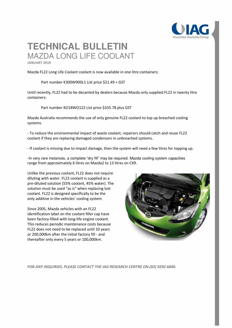
Unlike the previous coolant, FL22 does not require
diluting with water. FL22 coolant is supplied as a
pre-diluted solution (55% coolant, 45% water). The
solution must be used “as is” when replacing lost
coolant. FL22 is designed specifically to be the
only additive in the vehicles’ cooling system.
Since 2005, Mazda vehicles with an FL22
identification label on the coolant filler cap have
been factory-filled with long-life engine coolant.
This reduces periodic maintenance costs because
FL22 does not need to be replaced until 10 years
or 200,000km after the initial factory fill - and
thereafter only every 5 years or 100,000km.
FOR ANY INQUIRIES, PLEASE CONTACT THE IAG RESEARCH CENTRE ON (02) 9292 6840.

TECHNICAL BULLETIN
ASSISTANCE IN THE SOURCING OF MAJOR PARTS ASSEMBLIES NOVEMBER 2009
This initiative is intended to improve customer service by identifying any supply problems before they impact
on the repair process.
Slow-selling complex assemblies are rarely carried in stock by parts distributors and often have to be sourced
overseas, resulting in considerable delay to repairs. Complex assemblies typically include: engine blocks,
transmission cases, engine and body wiring harnesses, complete bucket seats, etc.
Vehicle owners often expect a much faster turnaround time on repairs involving these parts than can
reasonably be provided by the car manufacturer.
In these circumstances, Motor Assessors are encouraged to check parts availability before committing to
repairs, to avoid inconvenience to customers.
The IAG Research Centre may be able to assist when major repairs require unusual parts to be replaced.
Motor Assessors should contact the Research Help Desk so that parts availability and the expected time of
delivery can be checked.
This information may help to manage customers’ expectations and perhaps help to contain repair costs.
Motor assessors should obtain the following information and email: [email protected]
� Make, model & VIN
� Name of the repairer
� The part number
� The contact details for the dealer and dealer’s order number if the part has already
been ordered
Or phone the Help Desk: Roy McInnes extn 26849 or Andrew Marshall extn 26850
The availability of replacement parts can often be traced through the car companies’ computer systems within
48 hours globally.

TECHNICAL BULLETIN
HEADLAMP BRACKETS REPLACEMENT PARTS LIST AUGUST 2009
Attached is the latest headlamp bracket replacement list. A number of new models have been added
and parts prices from previous entries updated.
In previous Technical Bulletins we explained how the remaining broken section of the bracket is cut
from the headlamp body and the replacement part attached with screws.
For further enquiries please contact IAG Research Centre on (02) 9292 6840.
Double Click below file to open latest headlamp bracket replacement list.
Cut through at this point.
Replacement
bracket
attached with
screws.

TECHNICAL BULLETIN
LASER BRAZED WELDING NOVEMBER 2008
Laser brazed continuous seam welding equipment is not currently available to the smash repair industry.
Therefore, vehicles manufactured with laser brazed continuous seam welded panels cannot be repaired
using the same methods and technology.
When replacing laser brazed continuous seam welded panels, a combination of resistance spot welding
and structural adhesives is required.
Images above are of a 2005 Volkswagen Golf. Replacement of a body side panel cannot be performed
without replacing the roof panel. However, the roof panel can be replaced without disturbing the side
panels.
Assessors and repairers should therefore consider the extra parts and labour cost involved when
replacing body side panels.
Laser brazed continuous seam welding has been adopted in the manufacture of vehicles due to
advantages such as:
• Increased body rigidity which results in improved safety and vehicle stability
• Production cost efficiencies
• Enables materials of varying thicknesses to be joined
The cross-sectional views below show the different ways that Volkswagen Golf body side and roof
panels are joined. The left side illustrates how both panels engage when joined using laser brazed
continuous seam welding. The right side illustrates the area where structural bonding is used so that
replacement panels can be joined in a repair situation.
Laser brazed continuous seam
weld attaches body side
panel to roof panel
Close-up of weld

Many manufacturers use laser brazed continuous seam welding on their vehicles, including:
Audi A3, Audi A4, Audi A6, Audi A8, Audi TT, Ford Mondeo, Mazda6, VW Golf 5, VW Polo,VW Jetta, VW
Bora, VW Toureg, VW Transporter,
For further information please contact the IAG Research Centre on (02) 9292 6840
Acknowledgments:
Technical and product information supplied by Henkel Australia Pty Ltd
For component replacement, the laser seam
weld is substituted with a beading of structural
bond adhesive
Manufacturer’s laser brazed continuous
seam weld
Roof panel
(sectional
view) Body side panel (sectional view)

TECHNICAL BULLETIN
REPAIRS TO ALUMINIUM ALLOY ROAD WHEELS NOVEMBER 2008
There are a number of issues that need to be considered in the repair of damage to aluminium alloy
road wheels.
Aluminium alloy is quite different to steel in that mechanically straightening it cold, or the application of
heat, will alter the characteristics of the metal - usually making it brittle. Aluminium has no fatigue limit,
so no matter how over-designed or lightly loaded a section is, eventually it will fail. (It may be in a
thousand years but it will fail). Steel, on the other hand, will never fail providing the stress applied is
below the fatigue limit.
The repair of alloy wheels is quite common, but the degree of damage being repaired varies widely.
With few exceptions, most alloy wheels are over-designed, ie: thicker than they need to be.
Once the wheel is repaired and painted, there is no way of knowing how it was done or what
qualifications the repairer had or what process was used. Naturally, a wheel failure could be
catastrophic and may be hidden in the event of a future collision.
This technical bulletin is intended to provide guidelines for alloy wheel repairs to assist assessing staff.
These guidelines are based on repair practices in North America.
1. No repairs should be allowed on the spoke or centre section of the wheel, except for cosmetic repairs
(ie scratches etc)
2. Cold straightening is allowed if the deformation is less than the material thickness and less than 10cm
in length.
3. Heat straightening is allowed if:
a) Temperature is restricted to less than 200 degrees Celcius
b) The length and depth of the wheel deformation considered repairable by heat straightening is no
more than 20% of the wheel diameter on the inner rim and 10% of the outer rim.
4. Welding repairs are only to be made to the rim beyond the tyre bead.
5. Repaired wheels must be identified and numbered by the repairer so that a future repair is not
attempted.
For any further assistance contact the IAG Research Centre on (02) 9292 6840

TECHNICAL BULLETIN
BI – XENON HEADLAMP FAULT CODES FEBRUARY 2007
Assessors and repairers should be aware of an additional expense which may be incurred on
Volkswagen and Audi vehicles with Bi-Xenon headlamps.
As part of the repair process the headlamp is removed and the vehicle is driven back and forth from
panel to paint shop. When the vehicle is being reassembled and the headlamp re-connected it may not
work. This is because each time the ignition is turned on the vehicle’s computers check the wiring and
circuitry for system faults. The disconnection of the headlamp will register as an interruption in the
system therefore creating a fault code. A Volkswagen/Audi service department will need to clear the
fault code before the headlamps will operate.
Fault coding is possible to avoid by a repairer
removing and replacing the headlamps
without the ignition being turned on although
in most repair scenarios this would be difficult.
Remember, Bi-Xenon headlamps only will fault
code.
It is likely that other vehicle makes may also
require fault codes to be cleared prior to the
correct operation of the headlamps.
Assessors may contact Industry Research for a cost estimate to clear the code.
Should you have any further enquiries, please contact the IAG Research Centre Help Desk on 02 9292-
6840 or internally on 26840.

TECHNICAL BULLETIN
TOYOTA PANEL ADHESIVES JUNE 2006
Assessors and smash repairers should consider the following when inspecting late and current model Toyotas.
In March 2001, a Technical Bulletin was published regarding the acceptable use of panel adhesives.
In summary the bulletin stated that the use of adhesives was acceptable providing it was being used where the vehicle
manufacturer had originally used adhesives to join panels and that the adhesive was purchased from the vehicle manufacturer.
This directive is still current.
The information below describes the reapplication of the adhesive between the quarter and wheel arch panels on a Toyota
Yaris. Toyota recommend the use of 3M8115 Auto Mix Panel Bond be used.
Step 1 Remove the bulk of the quarter panel and drill out the 5 or
6 spot welds either side of the adhered section of the wheel arch.
With a heat gun or similar, warm the adhered section of the
quarter panel and remove.
Continue to warm and scrape the remaining adhesive on the
wheel arch then finish off with a disc sander or belt grinder. This
will increase the bond between the panels when the adhesive is
reapplied.
Finally, solvent wipe, air blow and apply a weldable sealer only to
the area to be re-spot welded.
Step 2 Following a check on the new panel fit, deeply scuff the
inside of the quarter panel ensuring that the manufactures
electrophoretic coating (E coat) is well penetrated.
Solvent wipe and air blow the area where the adhesive is being
applied.
Apply a 3 mm bead to the inside quarter panel around where it is
expected to contact the wheel arch.
Inside the wheel arch lip on the quarter panel, apply a 10mm bead
of adhesive and spread evenly. This will assist in removing air
bubbles.
Sit the new panel onto the vehicle and when correctly aligned
apply 1 spot weld either side of the wheel arch to secure the panel.
Complete the remainder of the welding.
Drying Time Force dry 60°C - 1½ hours.
Air dry 24°C - 24 hours.
Body sealer should be applied to the underside of the wheel arch following the application of the primer.
Should you have any further enquiries, please feel free to contact IAG Research on 02 9292-6843 or internally 26843.

TECHNICAL BULLETIN
DOOR SKIN REPLACEMENT ALLOWANCES MAY 2006
This bulletin explains the inclusions of door skin replacement allowances following a number of
enquiries from Assessors and Smash Repairers.
1. The partial dismantling and reassembly of the door. Not all components need to be removed to
replace the door skin. It is assumed that items such as grommets or window mechanisms will be left in
position. These do not interfere with the replacement of the skin or the repainting of the door.
2. Removal and replacement of the door. This allowance includes the initial removal of the door,
refitting in the aperture when the skin has been removed and the final installation of the door after the
skin has been fitted and the inner frame painted.
3. The removal and replacement of the skin. Note, many door skins have an inner brace welded at the
top to support the waste mould. When schedules are being created, the Technicians' are unable to
determine whether the brace is supplied with the skin or needs to be unpicked from the old panel and
welded to the new. For this reason no time has been included, therefore requiring the Assessor to
negotiate an additional allowance with the repairer for this operation. Figure 1 shows the approximate
location of the brace.
4. Some doors have inner sound proofing sheets applied to inside the panel. Assessors will need to
negotiate the reapplication of this material with repairers.
5. The door skins on some models include the upper frame. In these instances the time to replace the
skin is inclusive of the whole skin. See figure 2.
If you have any further enquiries, please feel free to contact IAG Research Centre on 02 9292-6840 or
internally 26840.
TECHNICAL BULLETIN
REPAIRS TO NEW UNSOLD VEHICLES MARCH 2006
The following Bulletin may be useful when inspecting CGU commercial claims on new, unsold vehicles.
The information detailed below has been sourced from the New South Wales Office Of Fair Trading
under the heading of Warranties, Dealer disclosure of damage, New and demonstrator vehicles.
A Motor dealer is obliged to disclose damage in a new vehicle when:
• Replacement or repair of the whole part of any panel, structural member or component of the
vehicle by cutting and welding, by application of heat or by any other means occurred;
• Replacement of not less than 4 major external panels fitted to the vehicle by means of bolts,
screws or other mechanical fastening devices has occurred;
• It is water damaged.
In summary, the motor dealer is required by law to disclose to a buyer if welding or cutting has been
performed to either the outer panels, or the vehicle’s structure. Furthermore he must advise if 4 bolted
or clipped body panels have been changed.
Additional information may be obtained from the Office Of Fair Trading’s web site,
http://www.fairtrading.nsw.gov.au/Consumers/Motor_vehicles/Warranties.html
Should you have any further enquiries, please feel free to contact IAG Research Centre externally on
02 9292-6840 or internally 26840.

TECHNICAL BULLETIN
IAG PAINT LIST DESCRIPTION JULY 2005
The latest IAG Paint Group List is available via the NTAR website.
The list is created from a database of colours sent to us from PPG Automotive Coatings. The difference
between M1 and M2 is the quantity and cost of the tinters in the formula. As tinters and their quantities
vary between paint manufacturers, what may be an M1 on PPG could be an M2 on another system. In
these circumstances we will increase to the higher rate providing the smash repairer can provide
justification.
Please note that many paint companies cost out their colours by using a system of price groupings. See
diagram 1.
The paint companies price
groupings and IAG’s paint rates
are not always the same. That is, a
colour which is a price group 2 or
3 will not necessarily be an M2 or
an M3.
Previous versions of the IAG Paint
Group List should be discarded.
Should you have any further
enquiries, please feel free to
contact IAG Research on 02 9292-
6840 or extension 26840.

TECHNICAL BULLETIN
STANDOX 2K PLATINUM CLEARCOAT FEBRUARY 2005
A Mercedes Benz February 2004 Technical Bulletin advised that from June 2002 productions, clear over
based finished vehicles are being manufactured with a Teflon based material called Ceramiclear.
All models are affected except ‘M’ Class.
At the time of the February 2004 Bulletin, there were no refinishing materials available to duplicate the
properties of Ceramiclear.
In the 4th quarter of 2004, Standox released a material called Standocryl 2K Platinum Clear that
replicates Ceramiclear’s properties.
When Mercedes Benz vehicles are being refinished using this material there are a number of factors to
consider.
• Platinum Clear can only be used over Standox Basecoats. It will react if applied over another paint
manufacturer’s basecoats by either blistering or delaminating.
• This material can be blended with the aid of Standox 2K Smart Blend.
• Platinum Clear will not air dry, it must be baked at 65º - 70ºC or dried with Infrared heaters.
This is contrary to IAG’s policy regarding bake allowance on bumper bars and plastic components.
However, this material will not fully cure without force drying.
Standox recommend that the refinish area be sanded and polished using the appropriate materials.
At moment there are no additional allowances paid to repairers using this material.
If you have any further enquiries, please feel free to contact IAG Research Centre internally on 26840 or
externally 02 9292-6840.

TECHNICAL BULLETIN
MICRODOTS JANUARY 2005
BMW/Mini (from September 2001) and HSV, FPV (incl. Mustang), Porsche, Mitsubishi Ralliart 2002
models and Subaru (2003 models) have used microdots as a secondary identifier. Since then Audi and
Yamaha have also adopted microdots. The cars would normally carry a DataDot decal on one of the side
windows but these are often removed during window tinting.
What are they?
They are a small clear plastic disc about 1 mm in diameter and have
the vehicle’s make and VIN etched onto them. They are intended to
make the vehicle difficult to rebirth as the sheer number of dots
makes it virtually impossible to remove them all.
Where are they?
The dots are sprayed over the underside of the vehicle including
chassis rails, suspension components, brake callipers, engine, gearbox and cross members. Some
manufacturers spray them within the cabin. Most manufacturers also have the dots sprayed over the
compliance plate, with BMW only doing this recently. (See the table overleaf)
Viewing them
They are applied to the vehicle with a water-based adhesive that has a trace that responds to Ultraviolet
light with a brilliant purple iridescence. After finding the microdots using a hand held UV light, peel
some off using a small blade of some kind, place them on a piece of white paper and they can be viewed
in detail by using a low cost 30x magnifier.
Replacement dots
DataDot Technology Australia will produce replacement dots if requested in writing by an insurance
company. The replacement dots will have an ‘R’ as a prefix to the VIN to indicate that they are a
replacement microdot.
The following pages contain the location of microdots listed by manufacturer.
For more information contact IAG Research Centre on (02) 9292-6840.
Where are they applied?

BMW Subaru HSV FPV Mustang Mini Porsche Ralliart Audi
Compliance Plate X X X X X X X X
Build Plate X X X X X X X
ID Plate X X X X
Wheels X X X X X
Brake Calipers X X X X X X
Brake Rotors Backing
Plates
X
Front Suspension
Components
X X X X X X X X
Rear Suspension
Components
X X X X X X X X X
Engine X X inc.
Serial
Number
X inc.
Serial
Number
X X inc.
Serial
Number
X X X inc.
Serial
Number
X
Gearbox X X X X X X X X X
Cross Member X X X X X X X X X
Steering Rack X X X Cayenne
Only
X
Front Bumper X X X X X X X X X
Rear Bumper X X X X X X X X X
Chassis Rails X X X X X X X X X
Exhaust and/or
Mounts
X X inc.
Turbo
X X X X X X X
Bonnet X X X X
Boot or Hatch Lid X X X X X

BMW Subaru HSV FPV Mustang Mini Porsche Ralliart Audi
Spare Wheel Well X X X X
Spare Wheel X Maloo
Only
X X X
Tail Lights X
Drive Shaft X X
4WD Transfer
Case
X
Differential X X X X X X
Inside Doors X X X X
Seats X
Seat Tracks X X X
Under Dash X X
A/C Vents
Headlights X X X
Manifold X X

TECHNICAL BULLETIN
HEADLAMP RETAINING LJULY 2002
Some car companies now offer replacement mounting brackets for headlamps. This provides a
cost-effective alternative to plastic repairs on headlamps that are damaged in collisions.
Vehicles involved in front-end impacts often sustain damage to headlamp assemblies. Severe impacts
might crack lenses, but most impacts simply break the retaining lugs away from
lamps. If the lugs have remained with the vehicle, it is always an option to plastic weld the lugs back
onto the bodies of the lamps. This can be done by body repairers or by sublet specialists.
On certain models, attachment lugs are now
purchased and attached to lamps, in a fraction of the time and cost of plastic repairs.
The photograph below is of a headlamp from a Toyota Avensis, which was impacted as part of the
Low Speed Crash Test program conducted by IAG
extracted from the Avensis workshop manual and shows the installation of the replacement bracket.
The operation is very simple. The remaining broken section of the lug (indicated by the arrow) is cut
flush to the headlamp body, allowing a neat fit of the replacement part. The list price of the new
bracket is less than $15.00. All fo
While the holes on the top of the lamp are pre
brackets do require drilling. The allowance for replacement should be 0.30 hours for each of the top
brackets and 0.40 hours for each of the bottom and side brackets.
TECHNICAL BULLETIN
HEADLAMP RETAINING LUG REPLACEMENT
Some car companies now offer replacement mounting brackets for headlamps. This provides a
alternative to plastic repairs on headlamps that are damaged in collisions.
end impacts often sustain damage to headlamp assemblies. Severe impacts
might crack lenses, but most impacts simply break the retaining lugs away from the bodies of the
lamps. If the lugs have remained with the vehicle, it is always an option to plastic weld the lugs back
onto the bodies of the lamps. This can be done by body repairers or by sublet specialists.
On certain models, attachment lugs are now available as replacement brackets. New brackets can be
purchased and attached to lamps, in a fraction of the time and cost of plastic repairs.
The photograph below is of a headlamp from a Toyota Avensis, which was impacted as part of the
st program conducted by IAG Research. The drawing to the right has been
extracted from the Avensis workshop manual and shows the installation of the replacement bracket.
The operation is very simple. The remaining broken section of the lug (indicated by the arrow) is cut
flush to the headlamp body, allowing a neat fit of the replacement part. The list price of the new
bracket is less than $15.00. All four are available for this model.
While the holes on the top of the lamp are pre-drilled for the bracket screws, the lower and side
brackets do require drilling. The allowance for replacement should be 0.30 hours for each of the top
for each of the bottom and side brackets.
Cut through at this point.
UG REPLACEMENT
Some car companies now offer replacement mounting brackets for headlamps. This provides a
alternative to plastic repairs on headlamps that are damaged in collisions.
end impacts often sustain damage to headlamp assemblies. Severe impacts
the bodies of the
lamps. If the lugs have remained with the vehicle, it is always an option to plastic weld the lugs back
onto the bodies of the lamps. This can be done by body repairers or by sublet specialists.
available as replacement brackets. New brackets can be
purchased and attached to lamps, in a fraction of the time and cost of plastic repairs.
The photograph below is of a headlamp from a Toyota Avensis, which was impacted as part of the
Research. The drawing to the right has been
extracted from the Avensis workshop manual and shows the installation of the replacement bracket.
The operation is very simple. The remaining broken section of the lug (indicated by the arrow) is cut
flush to the headlamp body, allowing a neat fit of the replacement part. The list price of the new
drilled for the bracket screws, the lower and side
brackets do require drilling. The allowance for replacement should be 0.30 hours for each of the top
Replacement
bracket
attached with
screws.

TECHNICAL BULLETIN
UNACCEPTABLE TURBO MODIFICATIONS APRIL 2002
Recently we have seen an increase in the number of manufacturer fitted turbo charged vehicles.
Some models include Subaru’s WRX, Liberty and Forester, Nissan 200SX, Audi’s A3,
A4 and TT, Toyota Corolla and Echo Sportivo’s to name a few.
In order to up spec the performance of these vehicles, some owners are opting to modify the
turbo charged systems. However in many instances these modifications make the vehicles an
unacceptable risk for insurance. These modifications and a description of their function have
been tabled below.


NRMA Insurance will only offer cover to petrol fuelled vehicles which have turbo chargers fitted
by the manufacturer as standard equipment. However cover is offered to accessory turbo
chargers fitted to diesel fuelled vehicles.
If you are unsure of a turbo charger modification, contact one of the Product Support Specialist
in Motor and Home Underwriting on extension 29508.
TECHNICAL BULLETIN
PANELS ADHESIVES MARCH 2001
There are a number of companies such as 3M, Wurth and the Lord Corporation,
which produce metal bonding adhesives for use in repairing motor vehicles. This is
not new technology. Some may remember Volvo in the late 1970/80’s using adhesives
to bond roof panels and door skins. This was a product sold as a Volvo spare
part. Since then more manufacturers have adopted the use of adhesives in vehicle
construction, in particular door skins.
The adhesive companies have extensively researched the strength and durability of
their products by employing independent organizations to perform impact tests on
vehicles which have had panels attached with their products. In most instances the
results have been favourable. Their strength in shear, or the ability of two lapped
panels to be stretched apart is acceptable.
In the replacement of roof panels, these claims have attracted many repairers to use
adhesives as an alternative replacement method. However, this breaches our policy
of repairing vehicles as per the manufacturer’s recommendation. Where a panel has
been originally spotted, mig, braze or lap welded, our expectation is for the panel
to be reattached using that method. Similarly, if the vehicle manufacturer has used
an adhesive on a door skin then it should also be used in a repair situation.
Repairers who believe there is a cost advantage using adhesives should reconsider
their options. To replace a roof skin on a medium size vehicle takes approximately
one canister of sealer. The average cost of a 225 ml canister is $90.00. Like spot
welding, the panels being adhered have to be sanded clean. Comparing this to the
time to spot weld and dress the roof, the more expensive option is using adhesive.
If anyone has any further enquiries regarding the use of adhesives they may contact
the IAG Research Centre on 02 9292-6843.
TECHNICAL BULLETIN
RADIATOR FAILURE OCTOBER 1998
Denso Manufacturing Australia in conjunction with the NRMA Technical Department
have published a booklet on radiator failures and their causes. The booklet
gives pictorial examples, in colour of several of the main causes of radiator failure.
Included are the two which mostly concern the smash repair industry, chemical corrosion
and stray current electrolysis.
Briefly, chemical corrosion is caused by mixing two incompatible coolants and stray
current electrolysis is caused by the flow of electrical current through the cooling system.
Recently there have been a number of instances where radiators have failed due to
stray current electrolysis. Discussions have been forthcoming between smash repairers,
radiator repairers and ourselves about who should pay to rectify the failure. It is
the repairer's responsibility to return the vehicle to its pre-accident condition. This
includes checking that electrolysis does not exist in the radiator coolant. The operation
to remove and replace the radiator includes the preparation of mounting points
and the re-attachment of earth straps. Should assessing staff sight instances of electrolysis
they should advise smash repairers of their liability to rectify the problem.