Embed Size (px)
Citation preview
Experience In Motion
TECHNICAL BULLETIN
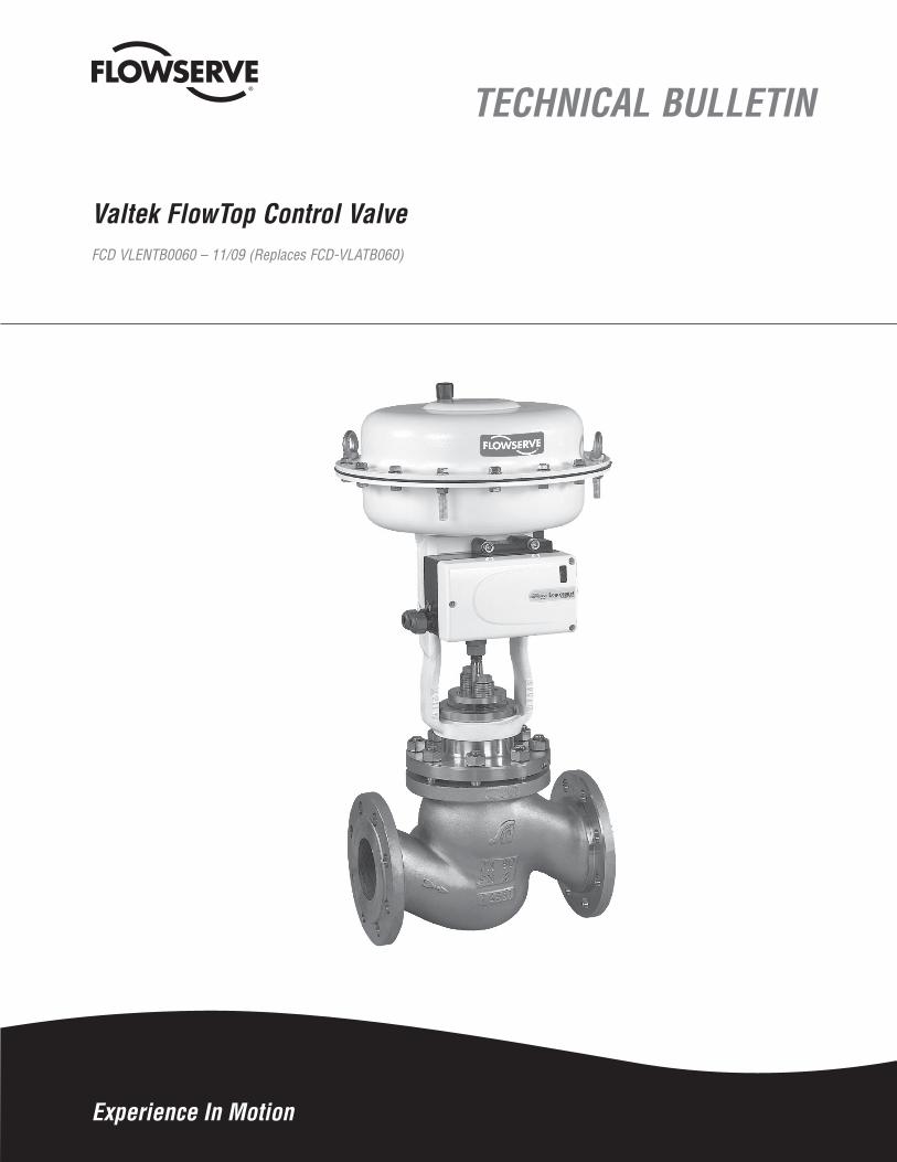
Valtek FlowTop Control ValveFCD VLENTB0060 – 11/09 (Replaces FCD-VLATB060)

Valtek FlowTop Control Valves FCD VLENTB0060-01 11/09
2
Body Assembly
Figure 1: FlowTop Control Valve Body Assembly
The FlowTop control valve is a high-performance, general service valve coupled with the high thrust FlowAct pneumatic diaphragm actuator.
The Logix 500 positioner is mounted standard on FlowTop control valves. The Logix 500 simplifies and reduces calibration time to 20 seconds or less by pushing two buttons. The easily installed HART compatible positioner make the FlowTop/Logix 500 combination the best choice for general service valve applications. There is no need for additional software or software support and upgrades. Handheld devices are not needed to calibrate this valve, making it the highest performing, low cost solution for general service valves.
The Pop-belly shaped gallery give the FlowTop more C than all the other globe valves on the market.
Designed for use in ANSI Class 150 or 300 service applications, the FlowTop control valve is capable of operating within temperatures ranging from -500 to 8000 F (-460 to 4270 C).
The FlowTop control valve is available in sizes 0.5 to 4 inches with a carbon steel or stainless steel body. It features flow under, single seated trim with a post-guided valve stem to eliminate cage guiding problems.
Heavy duty parts constructed of corrosion resistant materials provide extended valve life.
Zero external leakage at the body to bonnet joint: Graphite gasket eliminates leakage and minimizes torque requirements. Multiple equally spaced body bolts ensure optimal gasket loading
Stable plug travel over entire stroke of the valve: Solid, sturdy post style guide minimizes vibration and wear.
Very low seat leakage: A solid graphite seat gasket provides excellent shut-off. No lapping or grinding required to achieve class 4 shut-off. No more messy lapping compound.
Up to 10 Cv values available per valve size: No need to lap the plug and seat
Many high quality packing systems available: Including UltraGuard environmental packing, which exceeds EPA requirements. Certification for up to 5 years; no maintenance required (see Figure 18)
Highest globe valve Cv’s on the market: The pop belly shaped gallery enables flowTop to have higher Cv’s per trim size, and valve size than all other globe valves on the market.
3
Valtek FlowTop Control Valves FCD VLENTB0060-01 11/09
flowserve.com
Actuator Assembly
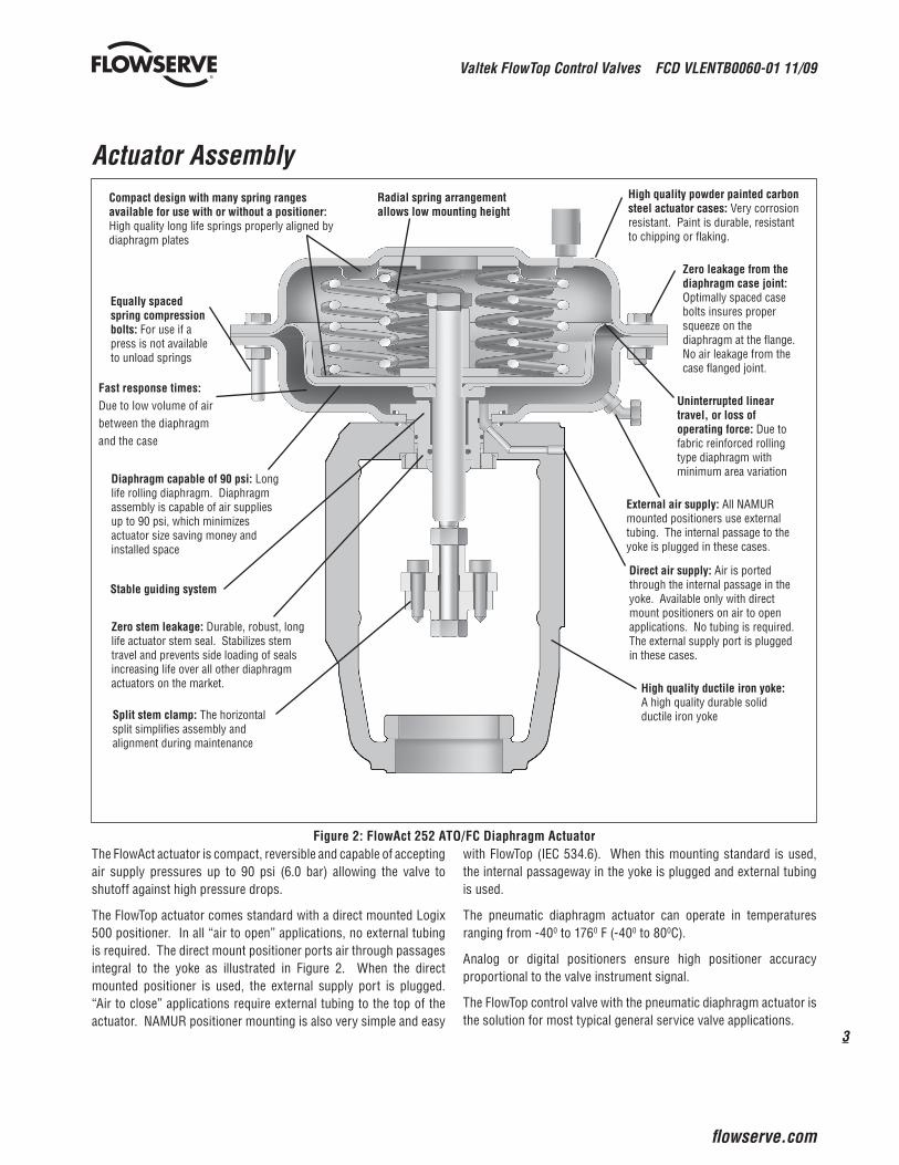
Figure 2: FlowAct 252 ATO/FC Diaphragm ActuatorThe FlowAct actuator is compact, reversible and capable of accepting air supply pressures up to 90 psi (6.0 bar) allowing the valve to shutoff against high pressure drops.
The FlowTop actuator comes standard with a direct mounted Logix 500 positioner. In all “air to open” applications, no external tubing is required. The direct mount positioner ports air through passages integral to the yoke as illustrated in Figure 2. When the direct mounted positioner is used, the external supply port is plugged. “Air to close” applications require external tubing to the top of the actuator. NAMUR positioner mounting is also very simple and easy
with FlowTop (IEC 534.6). When this mounting standard is used, the internal passageway in the yoke is plugged and external tubing is used.
The pneumatic diaphragm actuator can operate in temperatures ranging from -400 to 1760 F (-400 to 800C).
Analog or digital positioners ensure high positioner accuracy proportional to the valve instrument signal.
The FlowTop control valve with the pneumatic diaphragm actuator is the solution for most typical general service valve applications.
Compact design with many spring ranges available for use with or without a positioner: High quality long life springs properly aligned by diaphragm plates
Diaphragm capable of 90 psi: Long life rolling diaphragm. Diaphragm assembly is capable of air supplies up to 90 psi, which minimizes actuator size saving money and installed space
Stable guiding system
Zero stem leakage: Durable, robust, long life actuator stem seal. Stabilizes stem travel and prevents side loading of seals increasing life over all other diaphragm actuators on the market.
Radial spring arrangement allows low mounting height
Equally spaced spring compression bolts: For use if a press is not available to unload springs
Uninterrupted linear travel, or loss of operating force: Due to fabric reinforced rolling type diaphragm with minimum area variation
External air supply: All NAMUR mounted positioners use external tubing. The internal passage to the yoke is plugged in these cases.
Direct air supply: Air is ported through the internal passage in the yoke. Available only with direct mount positioners on air to open applications. No tubing is required. The external supply port is plugged in these cases.
High quality ductile iron yoke: A high quality durable solid ductile iron yoke
Fast response times: Due to low volume of air between the diaphragm and the case

Valtek FlowTop Control Valves FCD VLENTB0060-01 11/09
4
Body and Actuator Assembly
Figure 3: FlowTop Control Valve Assembly
Upper and Lower Diaphragm Cases
Packing Follower
External Air Supply
Stem Nut
Bonnet Gasket
Diaphragm Plate
3 Spring Compression Bolts
Actuator Nut
Body
Stem Guide
Name Plate
Case Bolts
Actuator Stem
Seat Gasket
Springs
Plug
Packing System
Split Stem Clamp
Yoke Nut
Seat Ring
Bonnet Flange (Integral to Bonnet)
Stem Seal Assembly and Guide Assembly
Body Bolting
Thread Covers
Packing Studs
Plug Stem
Yoke
Diaphragm
Vent
Bonnet

5
Valtek FlowTop Control Valves FCD VLENTB0060-01 11/09
flowserve.com
Features and AdvantagesFeatures AdvantagesLogix 500 Digital Positioner Logix 500 digital positioner reduces calibration time to 20 seconds by pushing
one button.
Either standard direct or NAMUR (IEC 534.6) positioner mounting available
Easy to install, HART compatible positioners make the FlowTop/Logix 500 the best valve/positioner combination for general service needs
No software or handheld device is required and can be configured locally
Good Shut-off FlowTop control valves offer class 4 shut off without the need for lapping the seating surfaces. Unlike most conventional valves, the FlowTop seat ring has a seat gasket, providing very good shut off.
Post Guiding Eliminates cage guiding problems
One solid, sturdy guide stabilizes the stem and plug during entire travel and minimizes vibration and wear.
Low Noise Trim Silent Pac Low Noise baffle can reduce noise levels generated by vapors and gasses.
Economical Stainless Steel Bellows Assembly Bellows assembly used for tough sealing applications, like Dowtherm, steam and others
Compact Engineered for applications with limited available installation clearance
ANSI Body Designed for use in ANSI Class 150 and 300 service, flanged applications
Easy Maintenance Bonnet design allows for quick, top-entry service. The valve body can remain in line while trim is changed or replaced.
Versatile Packing Configuration Available sets include single PTFE V-ring, PTFE braid and graphite. Live loading kits are available (see Figures 13 to 20).
Fugitive Emission Packing High quality “Ultra seal” environmental packing is available: Exceeds EPA standards of 500 ppm (see Figure 18).
Long-life Operation Heavy duty parts provide extended life, corrosion resistant construction
Many Positioning Options The valve can be equipped with a high performance analog or digital positioner or function without a positioner on air signal alone.
Wide Variety of Trim Sizes and Materials Up to 10 Cv values per valve size and many material options
High-Thrust Diaphragm Actuator Compact, light weight, capable of 90 psi (6.0 bar) air supply; multiple spring combinations. Reduces installation size and initial expense.
Dynamic Stability Sturdy guiding system stabilizes plug travel
Reversible Actuator Failure mode is easily reversed, using common tools
NAMUR Mounting (IEC 534.6) as an option Easy positioner mounting with universal NAMUR mounting kit
Support for products such as limit switches and position transmitters are easily mounted on the same NAMUR positioner bracket
Many Available Options Top-mounted handwheel, digital positioners, position transmitter, limit switches, proximity switches, and solenoids. (See Performance! software for specific details.)
Multiple Applications Usage High-performance, general service control valve used in many process indus-tries including chemical, refinery, power, food and beverage, HVAC and OEM
Valtek FlowTop Control Valves FCD VLENTB0060-01 11/09
6
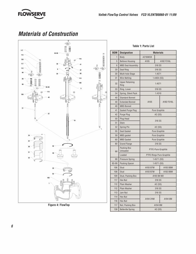
Table 1: Parts List
BOM Designation Materials
1 Body A216WCB
5 Bellows Housing A105 A182 F316L
6 MBS Seal Assembly 316 SS
20 Seat Ring 316 SS
30 Multi-hole Stage 1.4571
31 Wire Netting 1.4404 (SS)
32Upper Retaining Ring
1.4571
33 Ring, Lower 316 SS
34 Spring, Silent Pack 1.4310
40 Standard Bonnet
A105 A182 F316L40 Extended Bonnet
40 MBS Bonnet
41 Gasket Purge Plug Pure Graphite
42 Purge Plug A2 (SS)
50 Plug Head316 SS
51 Stem
52 Spring Pin A2 (SS)
55 Seat Gasket Pure Graphite
59 MBS gasket Pure Graphite
60 MBS Gasket Pure Graphite
80 Grand Flange 316 SS
88
Packing Box Unloaded
PTFE-Pure-Graphite
Loaded PTFE-Rings Pure-Graphite
90 Pressure Spring 1.4571 (SS)
93-99 Packing Spacer 1.4571 (SS)
106 Stud A193 B7M A193 B8M
108 Stud A193 B7M A193 B8M
109 Stud, Packing Box A193 B8 M2
117 Hex Nut 316 SS
112 Plain Washer A2 (SS)
112 Plain Washer 316 SS
113 Jam Nut 316 SS
114 Hex NutA194 2HM A194 8M
116 Hex Nut
117 Nut, Packing Box A194 8M
138 Belleville Spring A2 (SS)
Materials of Construction
Figure 4: FlowTop
58
20
55
108
1
31
30
32
34
33
50
93-99
59
8
40
116
16
41
42
60
113
106
5
117
112
138
117
112
80
88
90
93-99
109
51
114
40
52

7
Valtek FlowTop Control Valves FCD VLENTB0060-01 11/09
flowserve.com
Options
Figure 5: Bellow 2 inches and smaller (shown with a Silent Pac Low Noise
Baffle)
Figure 7: Silent Pac Low Noise Baffle used for gases and vapors
Figure 6:” Bellow 3-4 inches
Figure 8: PTFE Soft Seat(Minimum Trim Number is 0.24 inches [6 mm]
Figure 10: Trim with Alloy 6 Full-contour Overlay
Figure 9: Standard Trim with Alloy 6 Seat-surface Overlay
PTFE Soft Seat Insert

Valtek FlowTop Control Valves FCD VLENTB0060-01 11/09
8
Body Specifications and Design Options
Table 2: Valve Body Specifications
Style Top-entry, single seated, straight-through globe valve
Sizes 0.5 to 4-inch, ANSI Class 150-300 Flanged
End connection Integral flange
ISA 75.03
Surface finish Standard: 125 - 250 Ra
Optional: 250 - 500 Ra
Bonnet Standard, extended and bellows seal
Packing PTFE V-ring, braided PTFE, graphite, UltraGuard environmental packing systems
Trim flow characteristics
Linear, equal percentage, quick-open; unbal-anced
Leakage rates ANSI Class IV, VI (with soft seat option) Minimum trim number with soft seat is 0.24 inches
Design OptionsUnlike other general service valves, the FlowTop control valve offers a number of design and accessory options - including a versatile packing box with numerous packing configurations, fugitive emission option, multiple actuator spring configurations, top-mounted hand wheels, and a wide range of digital or analog positioners.
Figure 11: FlowTop with a direct mounted Logix 500 digital positioner - local calibration, no need of handheld device or
software.
Figure 12: FlowTop with a NAMUR mounted Logix 3000MD series digital positioner - local calibration, no need of handheld
device or software.

9
Valtek FlowTop Control Valves FCD VLENTB0060-01 11/09
fl owserve.com
Cv Tables
Table 3: Cv values for Modified Equal Percent
Valve Size
Inches
Trim Number Stroke Cv 100%
Inches mm Inches mm Cv KvS
0.5
0.63 16 0.787 20 6.5 5.6
0.47 12 0.787 20 4.6 4
0.39 10 0.787 20 2.9 2.5
0.31A 8 0.787 20 1.8 1.6
0.31B 8 0.787 20 1.16 1
0.24 6 0.787 20 0.73 0.63
0.16A 4 0.787 20 0.47 0.4
0.16B 4 0.787 20 0.29 0.25
0.16C 4 0.787 20 0.19 0.16
1
0.98 25 0.787 20 16.2 14
0.79 20 0.787 20 11.6 10
0.63 16 0.787 20 7.3 6.3
0.47 12 0.787 20 4.6 4
0.39 10 0.787 20 2.9 2.5
0.31A 8 0.787 20 1.8 1.6
0.31B 8 0.787 20 1.16 1
0.24 6 0.787 20 0.73 0.63
0.16A 4 0.787 20 0.46 .4
0.16B 4 0.787 20 0.29 0.25
0.16C 4 0.787 20 0.18 0.16
1.5
1.57 40 0.787 20 36 31.5
1.34 34 0.787 20 29 25
0.98 25 0.787 20 18.5 16
0.79 20 0.787 20 11.6 10
0.63 16 0.787 20 7.3 6.3
2
1.97 50 0.787 20 55 47.5
1.65 42 0.787 20 46 40
1.57 40 0.787 20 36 31.5
1.34 34 0.787 20 29 25
0.98 25 0.787 20 18.5 16
0.79 20 0.787 20 11.6 10
3
3.15 80 1.57 40 145 125
2.64 67 1.57 40 116 100
2.09 53 1.57 40 73 63
1.65 42 1.57 40 46 40
4
3.94 100 1.57 40 208 180
3.31 84 1.57 40 187 160
2.64 67 1.57 40 116 100
2.09 53 1.57 40 73 63
Table 4: Cv values for Linear
Valve Size
Inches
Trim Number Stroke Cv 100%
Inches mm Inches mm Cv KvS
0.50.63 16 0.787 20 6.5 5.6
0.47 12 0.787 20 4.6 4
1
0.98 25 0.787 20 16.2 14
0.79 20 0.787 20 11.6 10
0.63 16 0.787 20 7.3 6.3
0.47 12 0.787 20 4.6 4
1.5
1.57 40 0.787 20 36 31.5
1.34 34 0.787 20 29 25
0.98 25 0.787 20 18.5 16
0.79 20 0.787 20 11.6 10
0.63 16 0.787 20 7.3 6.3
2
1.97 50 0.787 20 55 47.5
1.65 42 0.787 20 46 40
1.57 40 0.787 20 36 31.5
1.34 34 0.787 20 29 25
0.98 25 0.787 20 18.5 16
0.79 20 0.787 20 11.6 10
3
3.15 80 1.57 40 145 125
2.64 67 1.57 40 116 100
2.09 53 1.57 40 73 63
1.65 42 1.57 40 46 40
4
3.94 100 1.57 40 208 180
3.31 84 1.57 40 187 160
2.64 67 1.57 40 116 100
2.09 53 1.57 40 73 63
Table5: Cv values for Quick Open
Valve Size
Inches
Trim Number Stroke Cv 100%
Inches mm Inches mm Cv KvS
0.5 0.63 16 0.787 20 7.3 6.3
1 0.98 25 0.787 20 18.5 16
1.5 1.57 40 0.787 20 41 35.5
2 1.97 50 0.787 20 61 53
3 3.15 80 1.57 40 162 140
4 3.94 100 1.57 40 231 200
Table 6: Silent Pac Cv values for Modified Equal Percent
Valve Size
Inches
Trim Number Stroke Cv 100%
Inches mm Inches mm Cv KvS
0.5
0.63 16 0.787 20 6.5 5.6
0.47 12 0.787 20 4.7 4
0.39 10 0.787 20 2.9 2.5
0.31A 8 0.787 20 1.9 1.6
0.31B 8 0.787 20 1.16 1
0.24 6 0.787 20 0.73 0.63
1
0.98 25 0.787 20 14.6 12.5
0.79 20 0.787 20 11.6 10
0.63 16 0.787 20 7.3 6.3
0.47 12 0.787 20 4.7 4
0.39 10 0.787 20 2.9 2.5
0.31A 8 0.787 20 1.8 1.6
0.31B 8 0.787 20 1.16 1
0.24 6 0.787 20 0.73 0.63
1.5
1.57 40 0.787 20 26 22.5
1.34 34 0.787 20 23 20
0.98 25 0.787 20 18.7 16
0.79 20 0.787 20 11.6 10
0.63 16 0.787 20 7.3 6.3
2
1.97 50 0.787 20 41 35.5
1.65 42 0.787 20 37 31.5
1.34 34 0.787 20 29 25
0.98 25 0.787 20 18.5 16
0.79 20 0.787 20 11.6 10
3
3.15 80 1.57 40 117 100
2.64 67 1.57 40 105 90
2.09 53 1.57 40 73 63
1.65 42 1.57 40 46 40
4
3.94 100 1.57 40 145 125
3.31 84 1.57 40 145 125
2.64 67 1.57 40 116 100
2.09 53 1.57 40 73 63
Table 7: Silent Pac Cv values for Linear
Valve Size
Inches
Trim Number Stroke Cv 100%
Inches mm Inches mm Cv KvS
0.50.63 16 0.787 20 6.5 5.6
0.47 12 0.787 20 4.6 4
1
0.98 25 0.787 20 14.7 12.5
0.79 20 0.787 20 11.6 10
0.63 16 0.787 20 7.3 6.3
0.47 12 0.787 20 4.6 4
1.5
1.57 40 0.787 20 26 22.4
1.34 34 0.787 20 23 20
0.98 25 0.787 20 18.5 16
0.79 20 0.787 20 11.6 10
0.63 16 0.787 20 7.3 6.3
2
1.97 50 0.787 20 41 35.5
1.65 42 0.787 20 37 31.5
1.34 34 0.787 20 29 25
0.98 25 0.787 20 18.5 16
0.79 20 0.787 20 11.6 10
3.15 80 1.57 40 117 100
2.64 67 1.57 40 105 90
32.09 53 1.57 40 73 63
1.65 42 1.57 40 46 40
4
3.94 100 1.57 40 145 125
3.31 84 1.57 40 145 125
2.64 67 1.57 40 116 100
2.09 53 1.57 40 73 63

Valtek FlowTop Control Valves FCD VLENTB0060-01 11/09
10
Packing
Non-Environmental Packing
Figure 13:V-ring Standard Bonnet
(Internal Live-loading Shown)
Figure 15:PTFE Ring Standard Bonnet
(Externally Live-loaded)
Figure 17:Graphite Ring
(Externally Live-loaded)
Figure 16:Graphite Ring
Figure 14:PTFE Ring Standard Bonnet
Extended Bonnet (Packing configuration only - extension not shown)
11
Valtek FlowTop Control Valves FCD VLENTB0060-01 11/09
flowserve.com
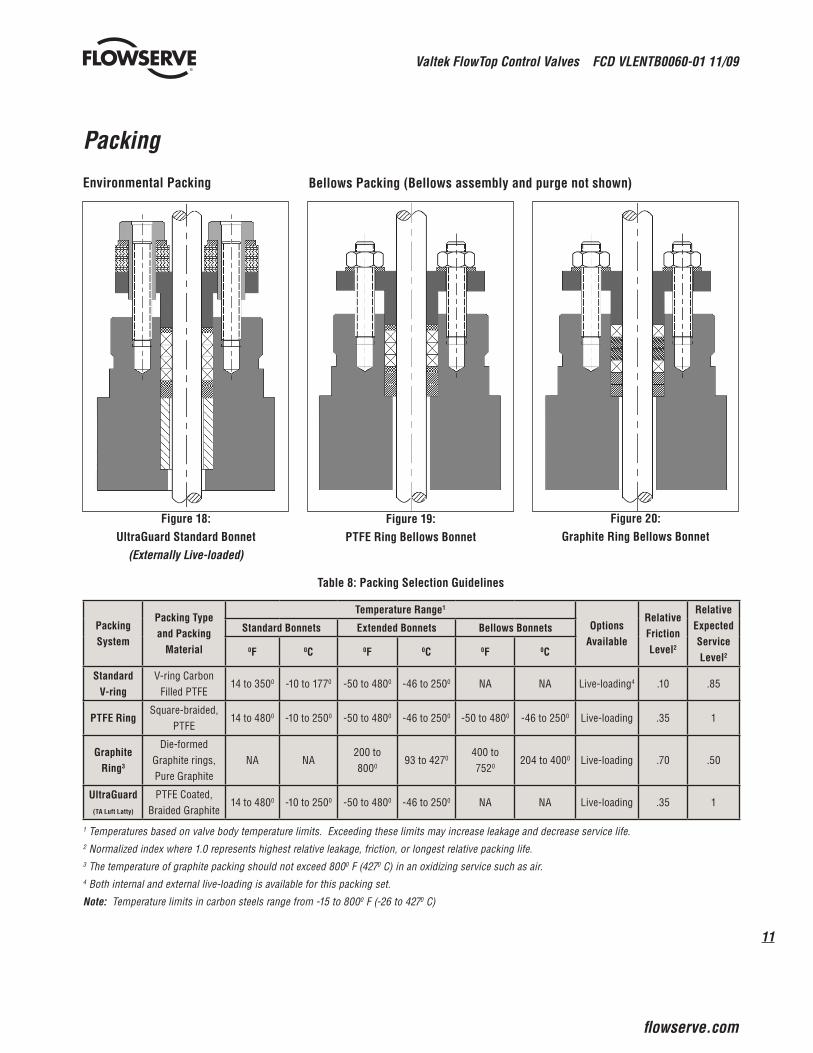
Figure 18:UltraGuard Standard Bonnet
(Externally Live-loaded)
Packing
Environmental Packing
Figure 20:Graphite Ring Bellows Bonnet
Figure 19:PTFE Ring Bellows Bonnet
Table 8: Packing Selection Guidelines
Packing System
Packing Type and Packing
Material
Temperature Range1
Options Available
Relative Friction Level2
Relative Expected Service Level2
Standard Bonnets Extended Bonnets Bellows Bonnets
0F 0C 0F 0C 0F 0C
Standard V-ring
V-ring Carbon Filled PTFE
14 to 3500 -10 to 1770 -50 to 4800 -46 to 2500 NA NA Live-loading4 .10 .85
PTFE RingSquare-braided,
PTFE14 to 4800 -10 to 2500 -50 to 4800 -46 to 2500 -50 to 4800 -46 to 2500 Live-loading .35 1
Graphite Ring3
Die-formed Graphite rings, Pure Graphite
NA NA200 to 8000
93 to 4270400 to 7520
204 to 4000 Live-loading .70 .50
UltraGuard(TA Luft Latty)
PTFE Coated, Braided Graphite
14 to 4800 -10 to 2500 -50 to 4800 -46 to 2500 NA NA Live-loading .35 1
1 Temperatures based on valve body temperature limits. Exceeding these limits may increase leakage and decrease service life.2 Normalized index where 1.0 represents highest relative leakage, friction, or longest relative packing life.3 The temperature of graphite packing should not exceed 8000 F (4270 C) in an oxidizing service such as air.4 Both internal and external live-loading is available for this packing set.
Note: Temperature limits in carbon steels range from -15 to 8000 F (-26 to 4270 C)
Bellows Packing (Bellows assembly and purge not shown)
Valtek FlowTop Control Valves FCD VLENTB0060-01 11/09
12
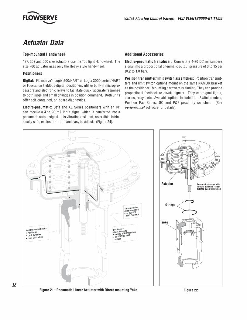
Actuator DataTop-mounted Handwheel
127, 252 and 500 size actuators use the Top light Handwheel. The size 700 actuator uses only the Heavy style handwheel.
Positioners
Digital: Flowserve’s Logix 500/HART or Logix 3000 series/HART or Foundation Fieldbus digital positioners utilize built-in micropro-cessors and electronic relays to facilitate quick, accurate response to both large and small changes in position command. Both units offer self-contained, on-board diagnostics.
Electro-pneumatic: Beta and XL Series positioners with an I/P can receive a 4 to 20 mA input signal which is converted into a pneumatic output signal. It is vibration resistant, reversible, intrin-sically safe, explosion-proof, and easy to adjust. (Figure 24).
Additional Accessories
Electro-pneumatic transducer: Converts a 4-20 DC milliampere signal into a proportional pneumatic output pressure of 3 to 15 psi (0.2 to 1.0 bar).
Position transmitter/limit switch assemblies: Position transmit-ters and limit switch options mount on the same NAMUR bracket as the positioner. Mounting hardware is similar. They can provide proportional feedback or on/off signals. They can signal lights, alarms, relays, etc. Available options include: UltraSwitch models, Position Pac Series, GO and P&F proximity switches. (See Performance! software for details).
Figure 21: Pneumatic Linear Actuator with Direct-mounting Yoke Figure 22
Solenoid Valve –
direct mounting
• on VDI/VDE
3845 E surface
NAMUR – mounting for:
• Positioner
• Limit Switches
• Limit Switch Box
Positioner –
direct mounting
• on SRD 009/1/2 surface
• on VDI/VDE 3847
surface
Actuator Pneumatic Actuator with integral pipework – stem extends by air failure ( s )
Yoke
O-rings

13
Valtek FlowTop Control Valves FCD VLENTB0060-01 11/09
flowserve.com
Actuator Data
Table 9: Parts List
Part Designation Materials203 Diaphragm Casing 1.03222
202 Diaphragm Casing 1.03222
335,336 Hexagon Bolt A2-70351 Hexagon Nut A2-70337 Plain Washer A2
257Guide Bush 1.07361
Plain Bearing -271 O-Ring NBR 70275 O-Ring NBR 70273 Scraper Ring NBR 90211 Stem 1.4571253 Spacer Bush 1.03081
228 Disk 1.07361
227 Diaphragm Plate 1.03321
225 Diaphragm NBR 60272 O-Ring NBR 70260 Thrust Washer 1.07361
349 Lock Washer Federstahl348 Hexagon Nut 17H1
229, 230 Actuator Spring 1.7102231 Distance Plate3 1.07361
326Spring Adjusting Plate
1.0330.031
258 Vent Plug Polyamid1 chromatised acc. to DIN 50 961 Fe/Zn 12C2 powder coating
Figure 23
335, 336
337
258
202
231
326
257
273
271
275
203
351
337
348
349
228
227
225
272
260
211
253
229, 230

Valtek FlowTop Control Valves FCD VLENTB0060-01 11/09
14
Actuator Dimensions and Weights
Table 10: Dimensions and Weights
Actuator Size 19 in2 (127 cm2) 39 in2 (252 cm20 78 in2 (502 cm2) 109 in2 (700 cm2)
Stroke 0.8 0.8 0.8 1.6 0.8 1.6Designation in cm in cm in cm in cm in cm in cmøA 7.8 178 10.4 254 13.9 330 13.9 330 15.9 381 15.9 381 H max. 12.6 305 13.2 330 17.9 432 18.1 457 21.5 533 21.7 533 Hs max. - - - - - - - - 34.3 864 34.4 864 Hl max. 23.2 584 23.4 584 33.3 838 34.3 864 - - - -øDs - - - - - - - - 13.8 330 13.8 330øDl 7.9 178 7.9 178 11.8 279 11.8 279 - - - -
Weight lb kg lb kg lb kg lb kg lb kg lb kg
Actuator 20 9 31 14 64 29 64 29 88 40 88 40With top mounted hand wheel “heavy” - - - - - - - - 12 5 12 5With top mounted hand wheel “light” 31 14 42 19 79 36 79 36 - - - -
Figure 24: Single-seat Trim
Table 11: Yoke Dimensions
Actuator Size 19 in2 (127 cm2) 39 in2 (252 cm20 78 in2 (502 cm2) 109 in2 (700 cm2)
Stroke 20 20 20 40 20 40
Designation in mm in mm in mm in mm in mm in mmøB 2.6 65 2.6 65 2.6 65 3.2 82 2.6 65 3.2 82≈M 4.1 105 4.1 105 4.1 105 5.5 140 4.1 105 5.5 140 G M12 M12 M12 M16 M12 M16 T .91 23 .91 23 .91 23 .98 25 .91 23 .98 25
øA
M(A
t 0%
s
trok
e
STRO
KE
T
øB
H m
ax.
G
Actuator size
øD
HL
max
.
Actuator with hand wheel
"light" Only available on
the 127, 252 & 502 actuators
HS
max
.
Actuator with hand wheel
"heavy"Used on 700 only
actuators
øDS
15
Valtek FlowTop Control Valves FCD VLENTB0060-01 11/09
flowserve.com
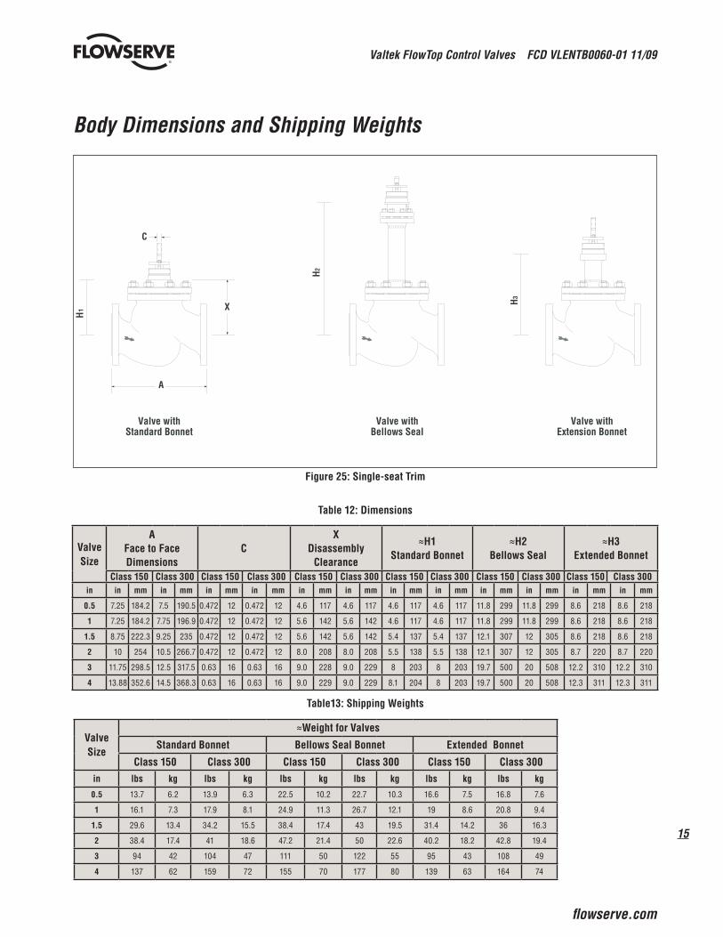
Body Dimensions and Shipping Weights
Figure 25: Single-seat Trim
Table 12: Dimensions
Valve Size
A Face to Face Dimensions
CX
Disassembly Clearance
≈H1 Standard Bonnet
≈H2 Bellows Seal
≈H3 Extended Bonnet
Class 150 Class 300 Class 150 Class 300 Class 150 Class 300 Class 150 Class 300 Class 150 Class 300 Class 150 Class 300in in mm in mm in mm in mm in mm in mm in mm in mm in mm in mm in mm in mm
0.5 7.25 184.2 7.5 190.5 0.472 12 0.472 12 4.6 117 4.6 117 4.6 117 4.6 117 11.8 299 11.8 299 8.6 218 8.6 218
1 7.25 184.2 7.75 196.9 0.472 12 0.472 12 5.6 142 5.6 142 4.6 117 4.6 117 11.8 299 11.8 299 8.6 218 8.6 218
1.5 8.75 222.3 9.25 235 0.472 12 0.472 12 5.6 142 5.6 142 5.4 137 5.4 137 12.1 307 12 305 8.6 218 8.6 218
2 10 254 10.5 266.7 0.472 12 0.472 12 8.0 208 8.0 208 5.5 138 5.5 138 12.1 307 12 305 8.7 220 8.7 220
3 11.75 298.5 12.5 317.5 0.63 16 0.63 16 9.0 228 9.0 229 8 203 8 203 19.7 500 20 508 12.2 310 12.2 310
4 13.88 352.6 14.5 368.3 0.63 16 0.63 16 9.0 229 9.0 229 8.1 204 8 203 19.7 500 20 508 12.3 311 12.3 311
Table13: Shipping Weights
Valve Size
≈Weight for Valves
Standard Bonnet Bellows Seal Bonnet Extended Bonnet
Class 150 Class 300 Class 150 Class 300 Class 150 Class 300in lbs kg lbs kg lbs kg lbs kg lbs kg lbs kg
0.5 13.7 6.2 13.9 6.3 22.5 10.2 22.7 10.3 16.6 7.5 16.8 7.6
1 16.1 7.3 17.9 8.1 24.9 11.3 26.7 12.1 19 8.6 20.8 9.4
1.5 29.6 13.4 34.2 15.5 38.4 17.4 43 19.5 31.4 14.2 36 16.3
2 38.4 17.4 41 18.6 47.2 21.4 50 22.6 40.2 18.2 42.8 19.4
3 94 42 104 47 111 50 122 55 95 43 108 49
4 137 62 159 72 155 70 177 80 139 63 164 74
Valve withStandard Bonnet
Valve withBellows Seal
Valve withExtension Bonnet
C
XH2
H1
H3
A

Valtek FlowTop Control Valves FCD VLENTB0060-01 11/09
16
Actuator Data
Table 14: Actuator Spring
Actuator Size StrokeSpring Code
Spring RangeSpring Color
Number of Springs
Spring Part Number
in2 cm2 mm psi bar
19.4 in2 127 cm2 20 mm
A 3-15 0.2-1.0 Blue 3 SMD-28602B 7-28 0.5-1.9 Blue 6 SMD-28602D 15-35 1.0-2.4 Red 3 SMD-28604F 29-70 2.0-4.8 Red 6 SMD-28604
U 22-55 1.5-3.8Blue 2 SMD-28602Red 4 SMD-28604
V 22-40 1.5-2.7 Silver 6 SMD-37482in2 cm2 mm psi bar
38.8 in2 252 cm2 20 mm
A 3-15 0.2-1.0 Blue 3 SMD-28605B 7-28 0.5-1.9 Blue 6 SMD-28605D 15-35 1.0-2.4 Red 3 SMD-28609F 29-70 2.0-4.8 Red 6 SMD-28609
U 22-55 1.5-3.8Blue 2 SMD-28605Red 4 SMD-28609
V 22-40 1.5-2.7 Silver 6 SMD-37483in2 cm2 mm psi bar
77.5 in2 502 cm2 20 mm
A 3-15 0.2-1.0 Blue 3 SMD-32097B 7-28 0.5-1.9 Blue 6 SMD-32097D 15-35 1.0-2.4 Red 3 SMD-32099F 29-70 2.0-4.8 Red 6 SMD-32099
U 22-55 1.5-3.8Blue 2 SMD-32097Red 4 SMD-32099
V 22-40 1.5-2.7 Silver 6 SMD-37486in2 cm2 mm psi bar
77.5 in2 502 cm2 40 mm
A 3-15 0.2-1.0 Blue 3 SMD-28610B 7-28 0.5-1.9 Blue 6 SMD-28610D 15-35 1.0-2.4 Red 3 SMD-28612F 29-70 2.0-4.8 Red 6 SMD-28612
U 22-55 1.5-3.8Blue 2 SMD-28610Red 4 SMD-28612
V 22-40 1.5-2.7 Silver 6 SMD-37485in2 cm2 mm psi bar
109 in2 700 cm2 40 mm
A 3-15 0.2-1.0 Blue 3 SMD-63752B 7-28 0.5-1.9 Blue 6 SMD-63752D 15-35 1.0-2.4 Red 3 SMD-63753F 29-70 2.0-4.8 Red 6 SMD-63753
U 22-55 1.5-3.8Blue 2 SMD-63752Red 4 SMD-63753
V 22-40 1.5-2.7 Silver 6 SMD-63754
17
Valtek FlowTop Control Valves FCD VLENTB0060-01 11/09
flowserve.com
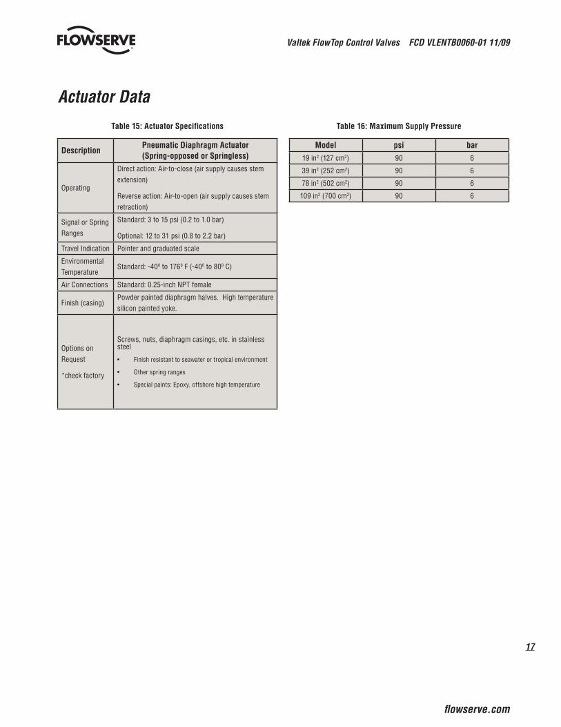
Actuator Data
Table 15: Actuator Specifications
DescriptionPneumatic Diaphragm Actuator(Spring-opposed or Springless)
Operating
Direct action: Air-to-close (air supply causes stem extension)
Reverse action: Air-to-open (air supply causes stem retraction)
Signal or Spring Ranges
Standard: 3 to 15 psi (0.2 to 1.0 bar)
Optional: 12 to 31 psi (0.8 to 2.2 bar)
Travel Indication Pointer and graduated scale
Environmental Temperature
Standard: -400 to 1760 F (-400 to 800 C)
Air Connections Standard: 0.25-inch NPT female
Finish (casing)Powder painted diaphragm halves. High temperature silicon painted yoke.
Options on Request
*check factory
Screws, nuts, diaphragm casings, etc. in stainless steel
Finish resistant to seawater or tropical environment•
Other spring ranges•
Special paints: Epoxy, offshore high temperature•
Table 16: Maximum Supply Pressure
Model psi bar19 in2 (127 cm2) 90 6
39 in2 (252 cm2) 90 6
78 in2 (502 cm2) 90 6
109 in2 (700 cm2) 90 6

Valtek FlowTop Control Valves FCD VLENTB0060-01 11/09
18
Model Codes
Type Size Class Body/Cert Plug Seat kvs Trim Actuator S
V740 DFVNA 2 inches 300 A216 WCB/00 PN1GG 42 46 316 SS
Packing Box Assembly
PTFE rings, adjustable, BAM APure graphite rings, adjustable, BAM BPTFE rings, loaded, BAM NPure graphite rings, loaded, BAM OPTFE rings, graphite core, load., “TA” QPTFE rings, oil lubricated, load., “TA” RV-ring packing S
Flow tends to open valve G
316 SS Plug, seat material400 SS Plug, seat material
Plug Guidance
Top 1
CharacteristicEqual percentage GLinear LOn/off A
PlugContoured plug PContoured plug with Silent Pac KDisk Plug (On/Off)
Plug TypeStandard NPartial Alloy 6 DFull Alloy 6 KSoft seated WHardened H
Port size 4 to 100
cv - value 0.012 - 208
Body material A216 WCB A351 CF8M
ANSI Class 150 150ANSI Class 300 300
Normal size 1/2 to 4 inches
Bonnet AssemblyStandard bonnet NBellows seal bonnet FExtension bonnet R
Body FormThree flange D
Bonnet FormWithout pressure balancing V
Form of ConnectionFlange acc. to ANSI B16.5 Form RF F
Valve ModelANSI 150 V738ANSI 300 V740
Materials CertificateWithout O.acc. EN 10 204 - 2.2Z Z.acc. EN 10 204 - 3.1B B.
Pressure and Leakage Certificate
Without .Oacc. EN 10 204 - 2.2Z .Zacc. EN 10 204 - 3.1B .B
Automatic safety valve - PED cat. IV .K
19
Valtek FlowTop Control Valves FCD VLENTB0060-01 11/09
flowserve.com
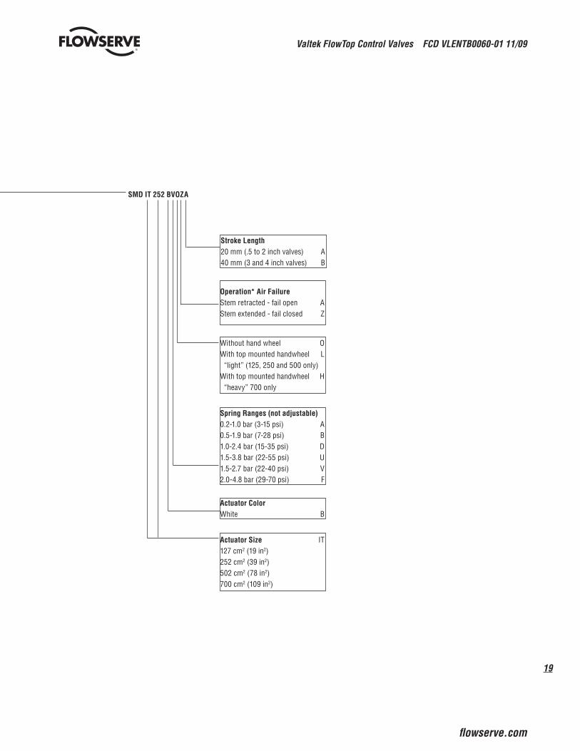
SMD IT 252 BVOZA
Stroke Length20 mm (.5 to 2 inch valves) A40 mm (3 and 4 inch valves) B
Spring Ranges (not adjustable)0.2-1.0 bar (3-15 psi) A0.5-1.9 bar (7-28 psi) B1.0-2.4 bar (15-35 psi) D1.5-3.8 bar (22-55 psi) U1.5-2.7 bar (22-40 psi) V2.0-4.8 bar (29-70 psi) F
Without hand wheel OWith top mounted handwheel L “light” (125, 250 and 500 only)With top mounted handwheel H “heavy” 700 only
Operation* Air FailureStem retracted - fail open AStem extended - fail closed Z
Actuator Size IT127 cm2 (19 in2)252 cm2 (39 in2)502 cm2 (78 in2)700 cm2 (109 in2)
Actuator ColorWhite B

flowserve.com
To find your local Flowserve representative:
For more information about Flowserve Corporation, visit www.flowserve.com or call USA 1 800 225 6989
Flowserve Corporation has established industry leadership in the design and manufacture of its products. When properly selected, this Flowserve product is designed to perform its intended function safely during its useful life. However, the purchaser or user of Flowserve products should be aware that Flowserve products might be used in numerous applications under a wide variety of industrial service conditions. Although Flowserve can (and often does) provide general guidelines, it cannot provide specific data and warnings for all possible applications. The purchaser/user must therefore assume the ultimate responsibility for the proper sizing and selection, installation, operation, and maintenance of Flowserve products. The purchaser/user should read and understand the Installation Operation Maintenance (IOM) instructions included with the product, and train its employees and contractors in the safe use of Flowserve products in connection with the specific application.
While the information and specifications contained in this literature are believed to be accurate, they are supplied for informative purposes only and should not be considered certified or as a guarantee of satisfactory results by reliance thereon. Nothing contained herein is to be construed as a warranty or guarantee, express or implied, regarding any matter with respect to this product. Because Flowserve is continually improving and upgrading its product design, the specifications, dimensions and information contained herein are subject to change without notice. Should any question arise concerning these provisions, the purchaser/user should contact Flowserve Corporation at any one of its worldwide operations or offices.
© 2009 Flowserve Corporation, Irving, Texas, USA. Flowserve is a registered trademark of Flowserve Corporation.
Manufacturing Facilities USA
1350 N. Mountain Springs PkwySpringville, UT 84663 USATelephone: +1 801 489 2300
Quick Response Centers
5114 Railroad St.Deer Park, TX 77536 USATelephone: +1 281 479 9500
2920 W. Cardinal Dr.Beaumont, TX 77705 USATelephone: +1 409 842 6600
12134 Inustriplex Blvd.Baton Rouge, LA 70809 USATelephone: +1 225 751 9880
1000 Eastern Star Road Ext.Kingsport, TN 37663 USATelephone: +1 423 349 4354
19 Creek ParkwayBoothwyn, PA 19061 USATelephone: +1 610 990 8710
6675 Daniel Burnham Dr.Clark BuildingPortage, IN 46368 USATelephone: +1 219 763 1000
FCD VLENTB0060-01 Printed in USA. (Replaces FCD-VLATB060)