Embed Size (px)
Citation preview

STATE OF CALIFORNIA DEPARTMENT OF CONSUMER AFFAIRS
BUREAU OF HOME FURNISHINGS AND THERMAL INSULATION 3485 ORANGE GROVE AVENUE
NORTH HIGHLANDS, CALIFORNIA 95660-5595
TECHNICAL BULLETIN 129
FLAMMABILITY TEST PROCEDURE FOR MATTRESSES FOR USE IN PUBLIC BUILDINGS
OCTOBER 1992

Standard Method for Room Fire Testing of Mattresses for use in Public Occupancies
1 SCOPE
1.1 The purpose of this test method is to determine the burning behavior of mattresses used in public occupancies by measuring specific fire-test responses when the mattress is subjected to a specified flaming ignition source under well ventilated conditions.
1.2 This test method is applicable only to the finished article of mattresses and other complete bedding systems and does not apply to testing of individual component materials used in the construction of bedding systems, such as ticking materials, foams, cotton battings, etc.
1.3 The public occupancies include, but are not limited to health care facilities, old age convalescent and board and care homes, college dormitories and residence halls.
1.4 Data are obtained describing the burning behavior from ignition until all burning has ceased, or a period of 1 hour has elapsed, or flashover appears inevitable.
1.5 Although this test method is primarily a test for mattresses, other bedding systems may be evaluated using procedures described in Appendix E.
1.6 The rate of heat release of the burning specimen is measured by an oxygen consumption technique.
1.7 Fire testing of products and materials is inherently hazardous and adequate safeguards for personnel and property shall be employed in conducting these tests. This standard may involve hazardous materials, operations, and equipment.
1.8 It is the intent of the Bureau that mattresses complying with this test method be safer when subjected to the ignition conditions specified by this method. This type of ignition may be typical of arson or incendiary fires or common accidental fires in public occupancies. The Bureau expects manufacturers and others attempting to comply with this method will also seek to make safer mattresses and will not attempt to compromise the intent of the method in any manner.
2 TEST CRITERIA
A mattress fails to meet the requirements of this test procedure if any of the following criteria are exceeded:
1. Weight loss due to combustion of 3 pounds or greater in the first 10 minutes of the test.
2. A maximum rate of heat release of 100 kW or greater.
3. A total heat release of 25 MJ or greater in the first 10 minutes of the test.
Note: These test criteria are applicable only when a single mattress is tested. 3 SUMMARY OF TEST METHOD
2

3.1 This standard determines a number of fire-test-response characteristics from a full scale mattress specimen, ignited with a propane gas burner, in a test room. Measurements to be made include rate of heat and smoke release, total amount of heat released, rates and concentrations of carbon oxides released, rates and amounts of mass of specimen lost. Other optional measurements are also described.
3.2 In options A and B, the mattress specimen to be tested is placed on a weighing platform, located in a test room. An exhaust hood, connected to an exhaust duct, is located at the doorway of the room.
3.4 In option C, the mattress specimen to be tested is placed on a weighing platform, located directly under a hood.
3.5 Heat, smoke and combustion gas release instrumentation is placed in the duct.
3.6 Additional instrumentation may be also placed in the room.
4 SIGNIFICANCE AND USE
4.1 This test method provides a means to measure a variety of fire-test-response characteristics resulting from burning a mattress specimen. The mattress specimen is allowed to burn freely under well ventilated conditions after ignition using a propane gas burner. The most important fire-test-response characteristic measured is the rate of heat release, which quantifies the intensity of the fire generated.
4.2 The rate of heat release is measured by the principle of oxygen consumption. Appendix C, and in particular C.1.4, discusses the assumptions and limitations.
4.3 Other fire-test-response characteristics measured, viz. smoke obscuration and combustion gas release, are also important in making decisions on fire safety.
4.4 The type of ignition chosen (flaming source) is common in both accidental and intentional fires in public occupancies. The test method is thus applicable to mattresses in public occupancies. Such facilities include, but are not limited to health care facilities, old age convalescent and board and care homes, college dormitories and residence halls.
4.5 This test method is not applicable to ignition of mattresses by cigarettes.
4.6 The test method has three options:
(A) The use of a test room with the following dimensions: 3.66 m x 2.44 m x 2.44 m high (12 x 8 x 8 ft).
(B) The use of a test room with the following dimensions: 3.66 m x 2.88 m x 2.44 m high (12 x 10 x 8 ft).
(C) The use of an open calorimeter (or furniture calorimeter).
3

(D) Rooms of other dimensions may be used where it can be shown that equivalent test results can be obtained.
4.7 For heat release rate values not exceeding 600 kW, the heat release rate measured with the specimen in the rooms of sizes shown in 4.6 has been found to be similar to that measured for a test specimen placed directly under the exhaust hood of a heat release rate calorimeter.
4.8 Measurements of temperatures, gas concentrations and smoke obscuration in the room are dependent on room size.
5 TEST SPECIMEN
5.1 The test specimen consists of an actual mattress.
6 ROOM LAYOUT AND INSTRUMENTATION
6.1 Test Room Layout (Option A)
6.1.1 The test room shall have dimensions of 2.44 m ±25 mm x 3.66 m ±25 mm x 2.44 m ±25 mm high (8 ft x 12 ft x 8 ft high). The room shall have no other openings than a doorway opening approximately 0.76 m ±6.4 mm x 2.03 m ±6.4 mm (30 in x 80 in), located as indicated in Figure 1, and other small openings, as necessary to make test measurements. Construct the test room of wooden or metal studs, and line it with fire rated gypsum wallboard. Position a hood outside of the room doorway, to extract all the combustion gases. There shall be no obstructions to the air supply of the test set-up.
6.2 Test Room Layout (Option B)
6.2.1 The test room shall have dimensions of 3.05 m ±25 mm x 3.66 m ±25 mm x 2.44 m ±25 mm high (10 ft x 12 ft x 8 ft high). The room shall have no other openings than a doorway opening approximately 0.97 m ±6.4 mm x 2.06 m ±6.4 mm (38 in x 81 in), located as indicated in Figure 2, and other small openings, as necessary to make test measurements. Construct the test room of wooden or metal studs, and line it with fire rated gypsum wallboard. Position a hood outside of the room doorway, to extract all the combustion gases. There shall be no obstructions to the air supply of the test set-up.
6.3 Open Calorimeter Layout (Option C)
6.3.1 The test enclosure shall be of sufficiently large dimensions that there are no spurious heat radiation effects from the walls or any other nearby objects. The airflow to the test specimen shall be symmetrical from all sides.
6.4 Other Test Room Furnishings
6.4.1 The test room shall contain no furnishings except for the item(s) to be tested. When full bedding systems are tested, as described in Appendix E, only the bedding components to be tested shall be in the test room.
4

6.5 Location of Specimen
6.5.1 Options A or B:
6.5.1.1 Position the mattress specimen and metal bed frame on a weighing platform in the corner so that the mattress is at a distance of between 10 and 25 cm (4 and 10 in) from both walls (Figures 1 and 2).
6.5.1.2 The preferred location for the mattress specimen is such that it faces the wall containing the doorway (Figures 1 and 2).
6.5.2 Option C:
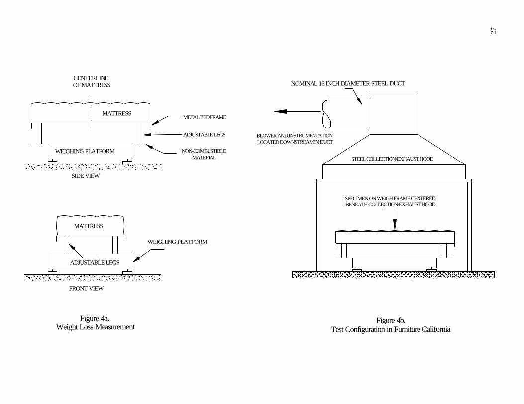
6.5.2.1 Position the mattress specimen and metal bed frame on a weighing platform underneath the hood (Figure 4-b).
6.5.3 The test specimen(s) shall be supported by a metal bed frame (Figure 4-a). The metal bed frame may be a conventional dormitory or prison cot. The bed frame shall be made of heavy angle-section iron with all joints welded and with sinusoidal no-snag type springs.
6.5.4 The distance from the lower surface of the test specimen to floor level shall be 50 ±5 cm (20±2 in).
6.6 Ignition Source
6.6.1 Ignite the mattress specimen with a gas burner, as described in Figure 3.
6.6.2 Construct the 205 mm (approximately 8 in) burner of 13±1 mm (0.5 in) OD stainless steel tubing, with 0.89±0.05 mm (0.035 in) wall thickness (Figure 3). The front side shall have 14 holes pointing at 45 degree angle straight out and spaced 13±1 mm (0.5 in) apart and 9 holes pointing at 45 degree angle inward and spaced 13±1 mm (0.5 in) apart. All holes shall be of 1±0.05 mm (0.039 in) diameter (see Figure 3). The straight arm of the burner shall be 1.07 m ±0.05 m (42 in) long and welded on to the rear of the front side (Figure 3) at a 30 degree angle. Mount the burner on an adjustable height pole and balance it by a counterweight or other appropriate mechanism (Figure 3).
6.6.3 Use commercial grade propane gas, with a known net heat of combustion of 2,050±50 kJ/mol, as a fuel for this ignition source. Meter the flow rate of propane and keep it constant throughout the test.
6.6.4 The approximate ratio of heat release rate output to gas flow rate is 1.485 kW min/l, under standard conditions.
6.6.5 Use the gas burner at a flow rate of 12 L/min for a total of 180 s. Measure the gas flow rate at a pressure of 101.3±5 kPa (standard atmospheric pressure) and a temperature of 20±5 o C.
6.7 Location of Gas Burner
6.7.1 The gas burner shall be positioned parallel to the bottom horizontal surface of the mattress and 25 mm (1 inch) from the vertical side panel of the mattress (Figure 3). The burner shall be positioned as indicated above with respect to the mattress, regardless of the use of bedding foundations or other bedding components.
5

6.8 Mass Loss Measurements
6.8.1 Use a weighing platform to continuously measure the mass loss of the burning specimen. The weighing platform shall consist of a horizontal non-combustible thermal barrier, placed on top of a mass measuring device (Figure 4-a).
6.8.2 The mass measuring device shall measure the specimen mass continuously with an accuracy of at least ±150 g up to at least 90 kg. Install it in such a way that the heat from the burning specimen and any eccentricity of the load does not affect accuracy. There shall be no range shifts during measurements. All parts of the mass measuring device shall be below the top level of the thermal barrier.
6.8.3 The distance from the lower surface of the thermal barrier to floor level shall not exceed 30 cm (12 in). The area between the thermal barrier and the floor level shall be shielded in order to avoid lifting forces, due to fire induced air flow, that influence the measurement.
6.8.4 Alternatively, a strain gauge weighing system may be used to measure the mass loss of the specimen in a test room. In this method, the bed frame may be suspended from the ceiling with chains (Figure 5) resulting in penetration through the ceiling of the test room. The hole at the ceiling should be kept at an absolute minimum size.
7 EXHAUST COLLECTION SYSTEM
7.1 General
7.1.1 The exhaust collection system shall consist of a blower, steel hood, duct, bi-directional probe, thermocouple(s), gas measurement system, smoke obscuration measurement system (white light photocell lamp/detector or laser), and combustion gas sampling system. It shall be constructed as shown in Figure A-1 and as explained in Appendix A.
7.1.2 The system for collecting the combustion products shall have a capacity and be designed in such a way that all of the combustion products leaving the burning specimen are collected without excessive make-up air (see Section A.1.4).
7.1.3 Place probes for sampling of combustion gases and for measurement of volume flow rate in the exhaust duct leading from the hood.
7.2 Details of Instrumentation in Exhaust Duct
7.2.1 The following specifications are minimum requirements, instrumentation. Additional information is found in Appendix B.
for exhaust duct
7.2.2 Volume Flow Rate
Measure volume flow rate in the exhaust duct by means of a bi-directional probe located at the center line of the duct. Measure the gas temperature in the exhaust duct by a thermocouple(see Appendix B.1 for further details). Measure the volume flow rate in the exhaust duct with an accuracy of at least ±6%. The response time
6

to a stepwise change of the duct flow rate shall be a maximum of 5 s to reach 90% of the final value.
7.2.3 Combustion Gas Analysis
7.2.3.1 Sampling Line
Take the combustion gas samples in the exhaust duct at a position where the combustion products are uniformly mixed. Make the sampling line tubes of a material not influencing the concentration of the combustion gas species to be analyzed. The recommended sequence of the gas train is: sampling probe, soot filter, cold trap, plastic drying column and carbon dioxide removal columns (if used), gas path pump, vent valve, flow controller and gas analyzers (see Figure 7 and Appendix B.2 for further details). The gas train shall also include appropriate spanning and zeroing facilities.
7.2.3.2 Specification for Oxygen Measurement
Measure the oxygen concentration with an accuracy of at least ±0.2% of full scale in the output range of 0 - 21 vol.% oxygen, or ±0.05 vol.% oxygen, in order to have adequate measurements of rate of heat release. Take the combustion gas sample from the end of the sampling line. Calculate the time delay, including the time constant of the instrument, from the test room; it is a function of the exhaust duct flow rate. It shall be a maximum of 30 seconds. (See Appendix B.3 for further details). A discussion of the calculations for rate of heat release is given in Appendix C.
7.2.3.3 Specification for Carbon Monoxide and Carbon Dioxide Measurement
Measure the combustion gas species with an instrument having an accuracy of at least ±0.1 vol.% for carbon dioxide and ±0.02 vol.% for carbon monoxide. A suitable output range is 0 - 1 vol.% for carbon monoxide and 0 - 6 vol.% for carbon dioxide. (Recommended upper limits of these ranges may be exceeded in flashover situation). Take the combustion gas sample from the end of the sampling line. Calculate the time delay, including the time constant of the instrument, from the test room; it is a function of the exhaust duct flow rate. It shall be a maximum of 30 seconds. (See Appendix B.3 for further details).
7.2.4 Measurement of Optical Density of Smoke
Install an optical system for measurement of light obscuration across the centerline of the exhaust duct, preceded by 12-30 diameters of duct. Determine the optical density of the smoke by measuring the light transmitted with a photometer system consisting of a lamp, lenses, an aperture and a photocell. Construct the system so that soot deposits during a test do not reduce the light transmission by more than 5%. Alternatively, instrumentation using a laser system instead of a white light system is acceptable (Figure 9).
7.2.4.1 Location
The light beam shall be directed across the diameter or cross section of the exhaust duct at a position where the smoke is homogeneous.
7.3 Calculations
7

7.3.1 Considerations for heat release measurements are presented in Appendix C. Calculate heat release data, using the equations presented in Appendix D.1. The testing laboratory shall choose which of the equations in Appendix D.1 it wishes to use for heat release calculations.
7.3.2 Calculate smoke release data using the equations presented in Appendix D.2.
8 CALIBRATION
8.1 Calibrate all instruments carefully with standard sources after initial installation. Among the instruments to be calibrated are load cells or weighing platforms, smoke meters, flow or velocity transducers, and gas analyzers. Perform re-calibration tests routinely on the entire system, for example using standard output burners.
8.2 Perform calibration of the mass measuring device by loading the weighing platform with known masses corresponding to the measuring range of interest, to ensure that the requirements of accuracy in Section 6.9.2 are fulfilled. Carry out this calibration daily, prior to testing.
8.3 Calibrate the smoke meter to read correctly for at least two different value neutral density filters, and also at 100% transmission. Carry out this calibration daily, prior to testing. Investigate any excessive departure from the zero line at the end of a test and correct it.
8.4 Calibrate gas analyzers daily prior to testing using "zero" and "span" gases, (see ASTM E800 standard guide for further details).
8.5 Perform calibration of the heat release instrumentation in the exhaust duct by burning propane or methane gas and comparing the heat release rates calculated from the metered gas input and those calculated from the measured oxygen consumption. The value of effective heat of combustion for methane is 50.0 MJ/kg and that for propane is 46.5 MJ/kg. Position the burner at the same location where the mattress specimen is to be placed during the test. Measure the gas flow rate at a pressure of 101.3±5 kPa (standard atmospheric pressure) and a temperature of 20±5 oC.
8.5.1 A suitable burner is a pipe, with an inner diameter of 100±1.5 mm (4 in), supplied with gas from beneath (ISO 9705). The gas for the burner flame shall not be premixed with air.
8.5.2 Another suitable calibration burner is a sand diffusion burner with a 0.3 m x 0.3 m (12 in x 12 in) top surface and a 0.15 m (6 in) depth. Construct such a gas burner with a 25 mm (1 in) thick plenum. Alternatively, use a minimum 100 mm (4 in) layer of Ottawa sand to provide the horizontal surface through which the gas is supplied. This type of burner is shown in Figure 6. The gas supply to the burner shall be propane, of the same quality as that used for the ignition burner, or methane, as described in Section 8.5. Meter the flow rate of gas and keep it constant throughout the calibration test.
8

8.6 Obtain a minimum of two calibration points. Obtain a lower heat release rate value of 40 kW and then a higher heat release rate value of 160 kW. Approximate propane flow rates for any required heat release rate value are estimated using the following constant: 1.485 kW min/l. Accurate flow rate of propane gas can be calculated using the mass flow rate equation for an orifice plate (Equation D1). Alternatively, a mass flow meter may be used to measure the flow rate of propane gas.
8.7 Take measurements at least once every 6 seconds and start 2 minutes prior to ignition of the burner. Determine the average rate of heat release over a 1 minute period by (a) the oxygen consumption method and (b) calculating the heat release rate from the mass gas flow rate and the effective heat of combustion. The difference between the two values shall not exceed 5%. This comparison shall be made only after steady state conditions have been reached.
8.8 Perform a calibration test according to Sections 8.5-8.7 prior to each continuous test series. Perform a full basic calibration on a new system or when modifications are introduced.
8.9 When calibrating a new system, or when modifications are introduced, it is recommended to check the response time of the measuring system by the following test sequence:
Time Burner output 0 - 5 minutes 0 kW 5 -10 minutes 40 kW 10-15 minutes 160 kW 15-20 minutes 0 kW
The response of the system to a stepwise change of the heat output from the burner shall be a maximum of 12 seconds to 90% of final value.
8.10 The precision of the system at various volume flow rates is checked by increasing the volume flow in the exhaust duct in four steps, starting from 0.25 m3 s-1 (at 0.1 MPa and 25°C) up to maximum. The heat output from the burner shall be 160 kW. The change in measured rate of heat release, comparing time average values over 1 minute, shall not be more than 10% of the actual heat output from the burner.
8.11 The use of a higher rate of heat release for calibration, for example 500 kW, will lead to higher accuracy in test results.
9 CONDITIONING
9.1 Prior to testing, condition the specimen for at least 48 hours in an atmosphere at a temperature of 23±3°C (73°F) and a relative humidity of 50±5%. Test specimens within 10 minutes of removal from such conditions if test room conditions differ from the above.
10 PROCEDURE
9

10.1 Initial Conditions
10.1.1 The ambient temperature shall be above 15°C (60°F) and the relative humidity shall be less than 75%.
10.1.2 The horizontal air flow, measured at the surface and at a horizontal distance of 0.5 m (20 in) from the edge of the weighing platform, shall not exceed 0.5 m s-1.
10.1.3 Position the specimen to be tested and metal bed frame centrally on the weighing platform.
10.1.4 Have available means for extinguishing a fully developed fire.
10.2 Test Procedure
10.2.1 Place the T-shaped propane gas burner at the side of the mattress, as specified in 6.7
10.2.2 Start all recording and measuring devices at least 1 min before starting the ignition burner.
10.2.3 Light the ignition burner.
10.2.4 Expose the specimen to the gas burner flames for 180 s, at a flow rate of 12 L/min.
10.2.5 After the specified burning period extinguish the gas flame and remove the burner.
10.2.6 Perform a photographic or a video recording before and during each test. A clock shall appear in all photographic records, giving time to the nearest 1 second.
10.2.7 Terminate the test after:
(1) all combustion has ceased*, or (2) 1 hour of testing has elapsed**, or (3) flashover appears inevitable.***
* Combustion is referred to both flaming and smoldering combustion. ** If the specimen is smoldering after 1 hour of testing has elapsed, remove the specimen from the test facility and extinguish with water completely. *** The test may be allowed to continue up to and beyond flashover, especially when using an open calorimeter, only if all safety precautions have been taken and there is no risk of hazard to the test operators and the test or other neighboring facilities.
11 TEST REPORT
The test report shall contain the following information:
11.1 Descriptive Information
11.1.1 Name and address of the testing laboratory.
10

11.1.2 Date and identification number of the report. 11.1.3 Name and address of the test requester. 11.1.4 Test option used: A, B or C. 11.1.5 Detailed description of the test specimens including dimensions. 11.1.6 Total initial weight of the specimen. 11.1.7 Date of test. 11.1.8 Test and sample model number.
11.2 Test Results (see also Appendix E).
11.2.1 Table of numerical results containing:
11.2.1.1 Peak rate of heat release (in kW), and the time at which it occurs 11.2.1.2 Total heat released at 10 minutes (in MJ) 11.2.1.3 Peak rate of smoke release (in m2 s-1), and the time at which it occurs 11.2.1.4 Total smoke released at 10 minutes (in m2) 11.2.1.5 Total weight loss at 10 minutes (kg)
NOTE
Studies on the flammability performance of mattresses indicate that bench scale fire tests may be used for evaluation of component materials for substitution purposes. The procedure is as follows:
1. Conduct full-scale fire test on the original mattress or bedding system.
2. If the original mattress complies with the requirements of the full-scale test method, conduct bench scale test(s) on combination of the component materials of the original mattress.
3. Conduct bench scale test(s) on the substitute component materials.
4. Compare the peak heat release and total heat release of the two bench-scale tests. If the corresponding values of the substitute materials are lower than those of the original mattress, a mattress made of the substitute components is expected to be in compliance with the full-scale test method.
5. If the substitute component materials produce higher heat release values than those of the original mattress, full-scale tests may be necessary to validate the fire performance of the substitute mattress.
For a complete description of bench scale test methods see NFPA 264A, "Standard Method of Test for Heat Release Rates for Upholstered Furniture Components or Composites and Mattresses Using an Oxygen Consumption Calorimeter".
11

APPENDICES
Appendix A
DESIGN OF EXHAUST SYSTEM
A.1 HOOD AND EXHAUST DUCT, RECOMMENDED DESIGN
A.1.1 The combustion gases from the burning specimen shall be collected by a hood. Below, a system is described which has been tested in practice and proven to fulfill the specifications given in the method.
A.1.2 The hood is located just outside the room doorway. The bottom dimensions of the hood are 2.4 m x 2.4 m (8 ft x 8 ft) and the height 1.0 m. On four sides, steel sheets are extended 1.0 m (3 ft 6 in) downwards. The effective height of the hood will thus be 2 m, see Figure A-1, and the distance between the lower edge of the hood and the floor (or weighing platform when using open calorimeter) shall be 1.5 -2 m. Larger size hoods are also acceptable. The hood feeds into a plenum having a 0.9 m x 0.9 m cross section area. The plenum has a height of 0.9 m. The maximum acceptable height is 1.8 m, depending on building constraints. In the plenum chamber two plates approximately 0.5 m x 0.9 m are located, see Figure A-1, to increase mixing of the combustion gases. The hood shall be designed and manufactured so that no leakage exists. A suitable means of mounting the laser beam together with the combustion gas sampling probes is shown in Figure A-2.
A.1.3 An exhaust duct is connected with the plenum chamber. The inner diameter of the exhaust duct is 405±5 mm (16 in). To facilitate flow measurements, guide vanes are located at both ends of the exhaust duct, Figure A-1. Alternatively, the rectilinear part of the exhaust duct must have such a length that a fully-developed flow profile is established at the point of measurement. The exhaust duct is connected to an evacuation system.
A.1.4 The capacity of the evacuation system shall be designed to exhaust all combustion gases leaving the specimen. This requires an exhaust capacity of at least 2.7 kg s-1 (about 8,000 m3 h-1 or 5000 CFM at standard atmospheric conditions) corresponding to a driving under pressure of about 2 kPa at the end of the duct. It shall be possible to control the exhaust flow from about 0.5 kg s-1 up to maximum flow as stated above during the test process. The system shall be capable of measuring low rates of heat release with sufficient sensitivity. If concentration gradients are found to exist, mixing vanes are an adequate means of addressing the problem.
A.1.5 Use of an alternative exhaust system design is limited to those systems shown to produce equivalent results. Equivalency is demonstrated by meeting the calibration requirements under Section 8.5. Exhaust system designs based on natural convection are not permitted.
Figure A-1. Design of hood and exhaust duct. A = min 3.35 m, B, C = min 0.30 m Figure A-2. Recommendations for mounting instrumentation in the exhaust duct.
12

Appendix B
INSTRUMENTATION IN EXHAUST DUCT
B.1 VOLUME FLOW
B.1.1 The flow shall be measured by a bi-directional probe, Figure B-1, located at the center line of the duct. The pressure difference between the two chambers is measured by a pressure transducer.
B.1.2 The pressure transducer shall have an accuracy of at least ±5 Pa and be of the capacitance type. A suitable range of measurement is 0 - 2,000 Pa.
B.1.3 Gas temperature in the immediate vicinity of the probe is measured by a Chromel-Alumel type K thermocouple shielded against high heat with insulation resisting up to 1200 °C. The wire gauge shall be 24 AWG or higher. The thermocouple shall be installed at the centerline of the duct and shall not be allowed to disturb the flow pattern around the bi-directional probe.
B.2 GAS SAMPLING LINE
B.2.1 The gas sampling probe shall be located in a position where the exhaust duct flow is well mixed. The probe shall have a cylindrical cross section so as to minimize disturbance of the air flow in the duct. Collect the combustion gas samples across the entire diameter of the exhaust duct (see Figure B-2).
B.2.2 Manufacture the sampling line, Figure 7, from corrosion resistant material, for example polytetrafluoroethylene. Remove the particulates contained in the combustion gases with inert filters, to the degree required by the gas analysis equipment. Carry out the filtering procedure in more than one step. The combustion gas samples taken to each analyzer shall be completely dried.
B.2.3 Transport the combustion gases by a pump, such as a diaphragm pump (coated with polytetrafluoroethylene), which does not emit oil, grease or similar products. The presence of such products in the stream will contaminate the combustion gas mixture. Alternate pumps shown to have the same effect are acceptable, but they have often been shown to need frequent replacement.
B.2.4 Two suitable sampling probes are shown in Figures B-2 and B-3. These sampling probes are bar type and cross-shaped, respectively. When these type of probes are not used, a ring type sampling probes is also acceptable. However, ring sampling probes will not allow combustion gas samples to be collected across the whole diameter of the duct. A suitable pump shall have the capacity of 10 - 50 L/min, as each combustion gas analysis instrument consumes about 2-3 L/min The pump shall generate a pressure differential of at least 10 kPa to reduce the risk of smoke clogging of the filters. The intake of the sampling probe is turned downstream in order to avoid soot clogging in the probe.
13

B.2.5 There shall be a soot filter, capable of removing all particles > 25 •m in size.
B.2.6 The recommended approach to a cooling column (to remove water from the combustion gases) is to use a refrigerated column with a drain plug from which the collected water is removed from time to time. Alternate devices shown to give equivalent results are also acceptable.
B.2.7 If carbon dioxide is to be removed, carbon dioxide removal media, as indicated in Figure 7, shall be used.
B.3 COMBUSTION GAS ANALYSIS
B.3.1 Oxygen Concentration
An oxygen analyzer, meeting the specifications under Section 7.2.3.2, shall be used. Paramagnetic type oxygen analyzers provide the most accurate measurement of oxygen concentration.
B.3.2 Carbon Monoxide and Dioxide Concentration
Non-dispersive infrared analyzers are found suitable CO/CO2 for measurements. Other types of analyzers may also be acceptable.
B.3.3 Time Shift
Combustion gas concentration measurements require the use of appropriate time shifts in order to account for combustion gas transit time within the sampling system.
Figure B-1 Bi-directional probe
Figures B-2 and B-3 Gas Sampling Probe
14

Appendix C
CONSIDERATIONS FOR HEAT RELEASE MEASUREMENTS
C.1 MEASUREMENT OF RATE OF HEAT RELEASE BY OXYGEN CONSUMPTION
C.1.1 INTRODUCTION
C.1.2 The objective of this section is to provide a comprehensive set of equations and guidelines to determine the rate of heat release in full-scale fire tests based on the principle of oxygen consumption.
C.1.3 The basic requirement is that all combustion products be collected in a hood and removed through an exhaust duct. At a distance downstream of the hood sufficient for adequate mixing, both flow rate and composition of the combustion gases are measured. The differences in treatment and equations to be used are mainly due to the extent to which combustion gas analysis is made. At least O2 shall be measured, but, if additional instrumentation is available, heat release rate measurements will be more accurate by measuring CO2 and CO additionally.
C.1.4 It must be emphasized that the analysis is approximate. The following list describes the main simplifying assumptions made:
· The amount of energy released by complete combustion per unit mass of oxygen consumed is taken as: E = 13.1 MJ/kg of O2.
· All combustion gases are considered to behave as ideal gases, in other words one mole of any gas is assumed to occupy a constant volume at the same pressure and temperature.
· Incoming air consists of O2, CO2, H2O, and N2. All "inert" gases, which do not take part in the combustion reactions, are lumped into the nitrogen.
· O2, CO2, and CO are measured on a dry basis, in other words, water vapor is removed from the sample before combustion gas analysis measurements are made.
C.1.5 In the analysis to follow, initial emphasis will be placed on the flow rate measurement. Equations to calculate flow rate are generally applicable, irrespective of the configuration of the combustion gas analysis system. In subsequent sections, distinction is made between various combustion gas analyzer combinations.
C.2 FLOW RATE MEASUREMENTS
C.2.1 To determine the flow rate in the exhaust duct, velocity at one point in the duct, usually along the center line, is measured. The flow rate is then calculated using a predetermined shape of the velocity profile in the duct. The latter is obtained by measuring velocity at a sufficient number of representative points over the diameter or cross section of the duct prior to any fire tests. Usually, conditions in full scale fire tests are such that the flow in the duct is turbulent, resulting in a shape factor kc (=ratio of the average velocity to the velocity along the centerline) close to 1.
15

C.2.2 Due to considerable soot production in many fires, pitot static tubes cannot be used because of clogging of the holes. In full-scale fire tests a more robust bi-directional probe is used. This involves measuring the differential pressure across the probe and the centerline velocity (Equation D2). This equation is generally preferred for full scale measurements of heat release rate.
C.3 RATE OF HEAT RELEASE MEASUREMENT IF ONLY OXYGEN IS MEASURED
C.3.1 In this case all water vapor and CO2 are eliminated by the use of appropriate filtering media. This leads to the assumption that the sample combustion gas only consists of O2 and N2. This is approximately true provided CO production is negligible. As the composition of the incoming air is unlikely to change during a test and as the temperatures in building fires are usually not high enough to generate noticeable amounts of nitrogen oxides by nitrogen fixation, the mole fraction of O2 in the air as measured by the analyzer prior to a test can be written on the basis of O2 and N2 exclusively. The mole fraction of O2 in the exhaust combustion gases, as measured by the oxygen analyzer, can be written likewise. As nitrogen is conserved and does not participate in the combustion reactions, the equations are derived on the basis of its conservation.
C.3.2 In this case the rate of heat released (in kW) is calculated as a function of the heat released per unit mass of oxygen consumed (E, 13.1 MJ/kg of O2), the ratio of the molecular weight of oxygen (M1, 32.0 kg/kmol) and the molecular weight of the incoming air (M2, generally taken as 28.97 kg/kmol), the mass flow rate of the incoming air (in kg/s). The flow rate measured is that of the smoke within the exhaust duct and not that of the incoming air. In order to find a relationship between the two it is necessary to define the oxygen depletion factor. The oxygen depletion factor is the fraction of the incoming air which is fully depleted of its oxygen (Equation D3). It can be demonstrated (see Appendix in ASTM E1354) that the rate of heat release is a function of E, M1, M2, and the oxygen depletion factor, plus the expansion factor. The expansion factor has to be assigned and a recommended value is 1.105, the value for methane. The value for carbon in dry air is 1.0 and for hydrogen is 1.21.
C.3.3 The resulting Equation, D4, is expected to be accurate to within ±5% provided combustion is complete, in other words, all carbon is converted to CO2. Errors will be larger if CO or soot production is considerable or if a significant amount of the combustion products are other than CO2 and H2O. It is unlikely that these errors will be of concern for a single mattress.
C.4 RATE OF HEAT RELEASE MEASUREMENT IF OXYGEN AND CARBON DIOXIDE ARE BEING MEASURED
C.4.1 This case is similar to that covered in the former section. It is now assumed that only water vapor is trapped before the sample reaches the combustion gas analyzers. Again, the equations, are derived on the basis of conservation of nitrogen. The mole fraction of CO2 in the incoming air is taken to be 440 ppm. A new equation is now needed, of course, for the oxygen depletion factor: Equation D6. Again the equation for rate of heat release (Equation D4) is accurate to within ±5% provided combustion is complete, in other words all carbon is converted to CO2.
16

C.5 RATE OF HEAT RELEASE MEASUREMENT IF OXYGEN, CARBON DIOXIDE AND CARBON MONOXIDE ARE BEING MEASURED
C.5.1 This case reverts to that covered in Section C.4 if CO production is negligible. Taking CO into account, however, changes the equations. It means that a new oxygen depletion factor is required, Equation D7, as well as a new rate of heat release equation altogether, Equation D8.
C.6 CONCLUSIONS
C.7.1 Depending on the configuration of combustion gas analyzers and the type of flow rate measurement, one of the following procedures shall be used to calculate rate of heat release:
C.7.2 Case 1: Only O2 is measured
* Calculate the mass flow rate of the exhaust combustion gases * Calculate the oxygen depletion factor * Calculate the rate of heat release
C.7.3 Case 2: Both O2 and CO2 are measured
* Calculate the mass flow rate of the exhaust combustion gases as in C.2.2 * Calculate the new oxygen depletion factor * Calculate the new rate of heat release
C.7.4. Case 3: O2, CO2, and CO are measured
* Calculate the mass flow rate of the exhaust combustion gases as in C.2.2 * Calculate the new oxygen depletion factor * Calculate the new rate of heat release
C.7.5 The following numerical values are recommended for use in the equations:
Energies: E = 13.1 MJ/kg of O2, ECO = 17.6 MJ/kg of O2
Molecular weights:
Ma = 29 kg/kmol (cases 1, 2, & 3), MCO = 28 kg/kmol, MCO2 = 44 kg/kmol, Mdry= 29 kg/kmol, Me = 29 kg/kmol (cases 1, 2, & 3), MN2 = 28 kg/kmol, MO2 = 32 kg/kmol Expansion factor = 1.105 (cases 1, 2, & 3).
C.7.6 Carbon dioxide is eliminated from the combustion gas sample because it interferes with the oxygen measurement. If a CO2 analyzer is used, this eliminates the need for removal of CO2 from the combustion gas sample. This is mainly of practical importance as the scrubbing agent used to remove CO2 usually requires careful handling and is rather expensive. If significant amounts of CO are produced (for example at or beyond flashover in ventilation controlled room fires), accuracy of the rate of heat release measurement is greatly improved if CO is measured.
17

D.1
Appendix D
Measurement Equations
Rate of Heat Release
Symbols are explained in D.4.
D.1.1 Flow Rate
Pressure differential measurement , using an orifice plate (Equation D1):
(D1)
Velocity measurement using bi-directional probe (Equation D2):
(D2)
D.1.2 Case 1: Only O2 is measured
Calculate the mass flow rate according to the Equation D2 and the oxygen depletion factor according to Equation D3:
(D3)
Then calculate the rate of heat release (q& ) according to Equation D4:
(D4)
if only O2 is measured, Equation D4 simplifies to Equation D5:
(D5)
D.1.3 Case 2: Only O2 and CO2 are measured
Calculate the mass flow rate according to the Equation D2 and the oxygen depletion factor according to Equation D6:
(D6)
18
and the rate of heat release according to the same Equation as in D.1.2 (Equation D4).
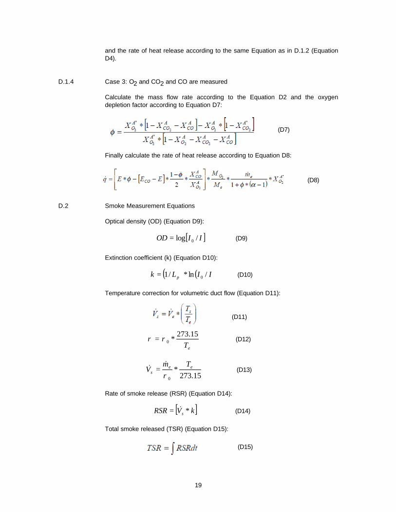
D.1.4 Case 3: O2 and CO2 and CO are measured
Calculate the mass flow rate according to the Equation D2 and the oxygen depletion factor according to Equation D7:
(D7)
Finally calculate the rate of heat release according to Equation D8:
(D8)
D.2 Smoke Measurement Equations
Optical density (OD) (Equation D9):
OD = log[I / I ]0 (D9)
Extinction coefficient (k) (Equation D10):
k = (1/ L )* ln (I / I )p 0 (D10)
Temperature correction for volumetric duct flow (Equation D11):
273.15ρ = ρ0 * Te
& m& e TeV = *s ρ0 273.15
(D11)
(D12)
(D13)
Rate of smoke release (RSR) (Equation D14):
RSR = [V& * k]s (D14)
Total smoke released (TSR) (Equation D15):
(D15)
19

(å([x]* m& ) )* Time * 0.001e scanf =s Number of scans * mass loss of specimen
D.3 Gas Yield Measurement Calculations
Calculate the gas yields (f) using the following equation (Equation D16):
(D16)
The numerator in this equation can be calculated by summing the product of the fraction of combustion gas by the total mass flow rate, measured at each scan, multiplying it by the total time period involved and dividing by the number of scans, as shown in Equation D17:
(D17)
In this equation, [x], the concentration of gas x, is expressed in ppm, m& , thee
mass flow rate, calculated by Equation D1 or D2, is expressed in kg/s, Time, the period over which the gas yield is calculated, is expressed in s, and mass loss of specimen, the mass lost over the period Time, is expressed in g, with 0.001 a conversion factor, to account for the unit changes.
Unless water concentrations are being measured, and this is not recommended, gas concentrations shall be reported on a dry gas basis.
20

D.4 Symbols:
m& : Mass flow rate in exhaust duct (in kg/s)e
C: Orifice plate coefficient (in kg½ m½ K½) Dp : Pressure drop across the orifice plate or bi-directional probe (in Pa)
Te:Gas temperature at the orifice plate (Equation D1) or combustion gas temperature at the bi-directional probe (Equation D2) (in °K) A: Cross sectional area of duct (in m2) kc: Velocity profile shape factor (non dimensional) q& : Rate of heat release (in kW) E: Net heat released for complete combustion, per unit mass of oxygen consumed (13,100 kJ/kg O2) α : Combustion expansion factor (non dimensional; normally a value of 1.105)
Ao
X O : Measured mole fraction of O2 in incoming air (non dimensional)2
A : Measured mole fraction of O2 in exhaust flow (non dimensional)X O2
Mdry: Molecular weight of dry air (29 kg/kmol) Ma: Molecular weight of incoming air (kg/kmol) Io: Light intensity for a beam of parallel light rays, measured in a smoke free environment, with a detector having the same spectral sensitivity as the human eye and reaching the photodetector I: Light intensity for a parallel light beam having traversed a certain length of smoky environment and reaching photodetector OD: Optical density (non dimensional) k: Extinction coefficient (in 1/m) Lp: Light path length of beam through smoky environment (in m) Ts: Duct temperature (near photodetector) (in °K)
V& : Volumetric flow rate in exhaust duct (at measuring location of mass flow rate)s
(in m3/s)
V& : Volumetric flow rate at location of smoke meter (value adjusted for smokes
measurement calculations) (in m3/s) ρ0 : Density of air at 273.15 K: 1.293 (in kg/m3)
ρ : Density of air at the temperature in the exhaust duct (in kg/m3)
RSR: Rate of smoke release (in m2/s) TSR: Total smoke released (in m2) φ : Oxygen depletion factor (non dimensional)
fx: Yield of gas x (in g/g) [x]: Concentration of gas x (in ppm)
21

Appendix E
TESTING OF BEDDING SYSTEMS
E.1 In addition to testing mattresses this test method may be used for any of the following bedding systems:
(a) A mattress and foundation, (b) A mattress with bed clothes, (c) A mattress and foundation with bed clothes, (d) Bed clothes only.
E.2 The standard bed clothes used in tests with bed clothes shall be two sheets, one pillow case, one acrylic blanket and one polyester filled pillow. The sheets and pillow case shall be either cotton or cotton/polyester. As an alternative, if a public building or facility has a prescribed or specified set of bed clothes, these may be substituted for the standard components described above.
E.3 When bed clothes alone is tested, a non-combustible substrate shall be used as an inert mattress. The inert mattress shall closely resemble the dimensions and feel of a typical mattress.
E.4 An inert mattress may be constructed by using fiberglass insulation batts of the desired thickness wrapped in fire barrier type cover fabric, such as fiberglass interliner material. The inert mattress should be pre-conditioned to minimize the potential contribution of the binder used in the fiberglass batts. Conditioning may be accomplished by covering the inert mattress with two bed sheets, which are ignited and burned prior to conducting actual tests.
22

APPENDIX F
NON-MANDATORY INFORMATION
F.1 Test Room Measurements
In addition to heat and smoke release measurements in the exhaust duct, some measurements in the room may be conducted. This information may be useful for comparison and/or correlation purposes.
F.1.1 Test Room Instrumentation
F.1.1.1 Figures 1-2 describe test room instruments.
F.1.1.2 Carry out room temperature measurement with Chromel-Alumel type K thermocouple, shielded against high heat with insulation resisting up to 1,200 oC. The wire gauge shall be 24 AWG or higher, and the thermocouple shall be mounted in one test location: at the geometric center of the ceiling, 100 mm (4 inches) below the ceiling (ceiling-center thermocouple).
F.1.1.3 Carry out density of smoke measurements with a smoke obscuration monitor, placed at a height of 1.22 m (4 ft) above the floor level. A white light or laser photometer system similar to that described for the duct will be suitable (See Section 7.2.4).
F.1.1.4 Carry out carbon monoxide concentration measurements with a gas sampling line located 165 mm (6.5 in) below the ceiling and 165 mm (6.5 in) from each wall of the corner where the specimen is placed (Figures 1 and 2).
F.2 Record of Events
F.2.1 During the test, record the following events and the time when they occur.
· Ignition of the specimen. · Position of flame front. · Melting and dripping. · Occurrence of pool fire under the specimen. · General description of the burning behavior. · Any other event of special interest.
F.2.2 Note the extent of damage to the specimen after the test.
F.3 Test Results - Additional Information
F.3.1 Numerical Results
F.3.2 F.3.3 F.3.4 F.3.5 F.3.6
Total mass loss (in kg). Peak concentration of carbon monoxide (in ppm). Gas yield of carbon monoxide and carbon dioxide. Peak temperatures (in °C). Report smoke obscuration, carbon monoxide and temperatures in the room in the same fashion.
23

F.3.2 Graphical Results
F.3.2.1 F.3.2.2 F.3.2.3 F.3.2.4 F.3.2.5 F.3.2.6 F.3.2.7 F.3.2.8 F.3.2.9 F.3.2.10
Plot of rate of heat release vs. time. Plot of rate of smoke release vs. time. Plot of optical density vs. time. Plot of mass loss vs. time. Plot of concentration of carbon monoxide vs. time. Plot of concentration of carbon dioxide vs. time. Plots of concentration of any other measured combustion gas vs. time. Plot of mass flow rate in the exhaust duct vs. time. Plot of duct temperature vs. time Report smoke obscuration, carbon monoxide and temperature measurements in the room in the same fashion, if they have been made.
F.3.3 Descriptive Results
F.3.3.1 F.3.3.2
Photographs or videotape, if available, of the fire development. All available information requested in Section 11.2.6.
FIGURES
Figure 1: Test room configuration for option A. Figure 2: Test room configuration for option B. Figure 3: T- Shaped Gas Burner Figure 4: Bed assembly - with platform load cell Figure 5: Bed assembly - with suspending strain gauge load cell Figure 6: Sand burner Figure 7: Schematic diagram of gas analysis system Figure 8: Optical system, using a white light Figure 9: Laser extinction beam
24

x
TC = THERMOCOUPLE
4-FT & CEILING THERMOCOUPLES
x
TEST BURN ROOM
VIDEO
CAMERA
Door TC
GAS SAMPLING LINE
CEILING CENTER TC
EXHAUST FILTERING SYSTEM
X
SMOKE OPACITY DETECTOR
SMOKE OPACITY LIGHT SOURCE
25
TEST BURN ROOM
X
X
1.2 m
SPECIMEN
3.66 mDETECTOR
SMOKE OBSCURATIONSMOKE OBSCURATION LIGHT SOURCE
0.76 m
2.44 m
+ Location of Smoke Obscuration Monitor Ceiling Thermocouple
Gas Sampling Line Figure 2
Test Room Configuration for Option BFigure 1 (Shown with Enclosure Room and Filtering System)Test Room Configuration for Option A
X

169 1818
12Top View
To gas supply (propane) 12 l/min
51 51
Bottom View
30°
Diameter of holes = 1.0 All dimensions in mm
¯
9 holes
90°
To gas supply
14 holes
End View
Figure 3-a. T-Shaped Gas Burner
SIDE VIEW OF PLACEMENT
MATTRESS
BED FRAME 1"
SIDE VIEW OF PLACEMENT WITH FOUNDATION
MATTRESS
BED FRAME 1"
Figure 3-b. Location of the T-Shaped Gas Burner 26
27
CENTERLINE NOMINAL 16 INCH DIAMETER STEEL DUCTOF MATTRESS
METAL BED FRAME
ADJUSTABLE LEGS BLOWER AND INSTRUMENTATION LOCATED DOWNSTREAM IN DUCT
NON-COMBUSTIBLE MATERIAL STEEL COLLECTION/EXHAUST HOOD
MATTRESS
WEIGHING PLATFORM
SPECIMEN ON WEIGH FRAME CENTERED BENEATH COLLECTION/EXHAUST HOOD
SIDE VIEW
MATTRESS
WEIGHING PLATFORM
ADJUSTABLE LEGS
FRONT VIEW
Figure 4a. Figure 4b.Weight Loss Measurement Test Configuration in Furniture California

LOAD CELL
PILLOW AND PILLOW CASE BLANKET
BOTTOM SHEET TUCKED IN
TOP SHEET
1'
Figure 5. A Test Configuration with Mattress and Bedding Using Strain Gauge Suspended from Ceiling
METAL BED FRAME 6"
2"
1' 6" 2"
SAMPLER
SOOT FILTER
SEPARATION CHAMBER
O2 ANALYZER
WASTE WASTE FLOW
REGULATOR CONTROLLER COLD TRAP
7 µM FILTER DESICCANT ROTAMETERCO2
REMOVAL PUMP MEDIA
TO CO2 AND CO ANALYZERSDRAIN
OUTFLOW
6"
6"
NOTE: SHOWN WITHOUT SAND
PLAN VIEW
SPACE FILLED WITH WHITE OTTOWA SILICA SAND
6"
1 3/4"
PROPANE FUEL
Figure 7. Schematic Diagram of Gas analysis System ELEVATION
Figure 6. Calibration Gas Burner
28

WALLS OF EXHAUST DUCT
L2
LAMP
L 1
DETECTOR
APERTURE
SMOKE PARTICLES
Figure 8. Optical System Using a White Light
0.5 MW HELIUM-NEON LASER
ALIGNMENT CRADLE
CAP
MAIN DETECTOR
FILTER SLOT
BEAM SPLITTER PURGE AIR ORIFICES
CERAMIC FIBER PACKING
OPTICAL PATH
COMPENSATION DETECTOR
OPTICAL GLASS
FILTER SLOT
SILICONE TUBING
Figure 9. Laser Extinction Beam
29

APPENDIX A
914
360
380
D0.
91 m
m(0
.036
in)
FLOW
SMOKE THERMOCOUPLELASER EXTINCTION BEAM
SMOKE THERMOCOUPLE
MASS SAMPLING PORT
BI-DIRECTIONAL PROBE
GAS SAMPLING PROBE
EXHAUST DUCT
A BC
A
A
PITOT TUBE
GUIDE VANES
STEEL PLATES 2 mm X 500 X 900 HOOD OF 2 mm STEEL PLATES
FRAME OF STEEL PROFILE
1000 X 2440 (OPTIONAL)
OPENING 2440 X 2440
240
•
4 STEEL PLATES 390 X 400
400
A
A
GUIDE VANES
DIMENSIONS IN MILLIMETERS
400
TO EXHAUST GAS CLEANING
OPENING 400
SECTION A--A CROSS SECTION GUIDE VANES
Figure A-1: Details of Exhaust System A = min 3350 mm B, C = min 30 mm
LASER MOUNTING VIEW OF GAS SAMPLING PROBE HOLES DOWNSTREAM TO AVOID CLOGGINGFigure A-2. Exhaust Duct Instrumentation
APPENDIX B
7.26 mm VARIABLE LENGTH SUPPORT TUBES(0.286 in) (TO PRESSURE TRANSDUCER)
4.70 mm (0.286 in)
WELD
50
HOLE 2
50
3HOLE
1010
EXHAUST DUCT
1.87 mm (0.072 in)
L=2D
Figure B.2. Gas Sampling Probe - Bar Type
Figure B.1. Bi-directional Probe
30

1"
14"
12"
1"
1"
SMALL HOLES (9) 3/32" DIAMETER LARGE HOLES (16) 1/8" DIAMETER DISTANCES BETWEEN HOLES = 1 IN.
14"
DUCT
AIR FLOW
31
ENDS PLUGGED
1"
1/2" OD SS TUBE
¯ TO GAS ANALYSIS SYSTEM
Figure B3-b Figure B3-a Side View of the Gas Sampling Probe in the Duct Front View of Cross-Shaped Gas Sampling Probe