Embed Size (px)
Citation preview
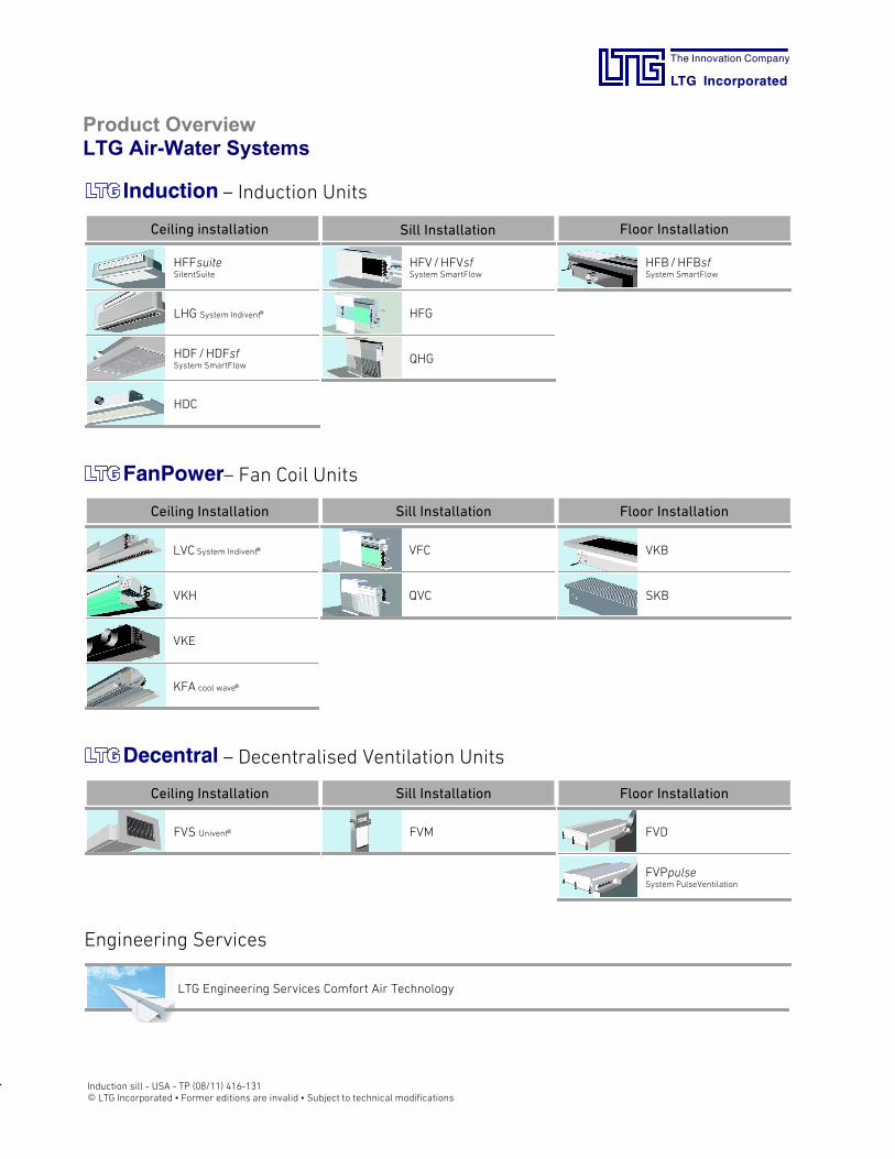
Technical Brochure
LTG Air-Water Systems
The Innovation Company
LTG Incorporated
Induction units
Sill installation
The Innovation Company
LTG Incorporated
E LTG Incorporated · PO Box 2889 · Spartanburg, S.C. 29304, USA Induction sill -USA-TP (08/11)Phone +1 864 599-6340, Fax +1 864-6344 · [email protected] · www.LTG-INC.netFormer editions are invalid · Subject to technical modifications page 2 of 29
Induction units for perimeter installation
LTG Comfort Air Technology
Air Diffusers
Air Distribution
Air-Water-Systems
Content Page
Induction units 3
Type HFG-0 2-pipe system 5
Type HFG-0 4-pipe system 7
Type HFK-0 4-pipe system 9
Type HFS 4-pipe system 11
Type HFG with bypass 2-pipe system 14
Type HFL 4-pipe system 16
Type HFH 4-pipe system 18
Type QHGperimeter displacement induction unit
20
Capacity charts 23
Example for selection 27
Connection of units 28
Damper actuators 29
Specifications and schedules of prices
NotesDimensions stated in this brochure are in inches and mm.
Dimensions stated in this brochure are subject to GeneralTolerances according to DIN ISO 2768-vL.For the outlet grille special tolerances stated in the drawingapply.
Straightness and twist tolerances for extruded aluminumprofiles according to DIN EN 12020-2.
The surface finish is designed to meet the requirements forapplications in buildings - room climate according to DIN1946 part 2. Other requirements on request.
The actual specifications are available as a word docu-ment at your local distributor or at www.LTG-INC.net.
The Innovation Company
LTG Incorporated
E LTG Incorporated · PO Box 2889 · Spartanburg, S.C. 29304, USA Induction sill -USA-TP (08/11)Phone +1 864 599-6340, Fax +1 864-6344 · [email protected] · www.LTG-INC.netFormer editions are invalid · Subject to technical modifications page 3 of 29
Induction units for perimeter installation
LTG offers air distribution with various flow patterns:
- Mixed/displacement flow from the sill
- tangential flow from the sill
- IndiventR flow from the ceiling
- displacement air flow from the sill
LTG-KlimaventR units are induction units formedium/high-pressure air conditioning systems.
The induction system is a combined air and water system:
- The air system ensures ventilation and room air humiditycontrol.
- Thewater system,which is very economical for the trans-port of energy, additionally heats or cools the air usingheat exchangers.
This provides the twomost significant features of the induc-tion unit: energy-saving operation and low space require-ments.
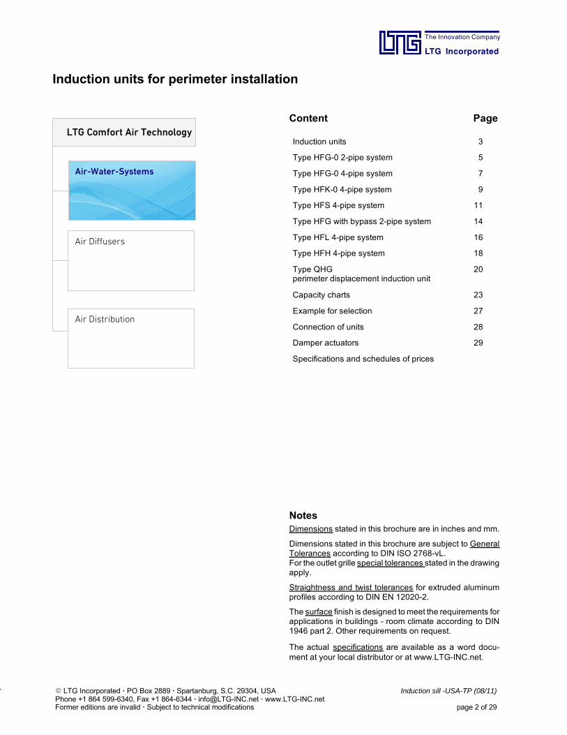
KlimaventR induction units with casing
Models and sizesLTG offers differents models and sizes for any application.The main distinctive feature of the LTG induction units isthe way the temperature is controlled.Each of the LTG induction units is available in five sizes:500 - 630 - 800 - 1000 - 1250.
Two-pipe systemThe induction unit has only one heat exchanger throughwhich chilled water flows for cooling and hot water for heat-ing. Therefore, it is only possible to either heat or coolwithina single water circuit.
Four-pipe systemThe induction unit has two separate water systems, one forheating, the other one for cooling. Therefore, chilled andhot water will always remain separated. The four-pipe sys-tem fulfills all requirements on varying loads and small con-trol zones.
Valve control (water-side control)The heating or cooling output of the heat exchanger is con-trolled by modifying the water flow.
Damper control (air-side control)The heating or cooling output is controlled by modifying theflow of secondary air. Adjustable dampers guide the airstream through the cooling or heating coil or they divert thesecondary air through a bypass around the heat ex-changers.
Advantages High cooling and heating capacitydue high performance heat exchanger
Low energy consumptiondue to high capacity natural convection
Low noisedue to special nozzle design and arrangement ofnozzles.
Flexible nozzle assemblydue to the availability of several sets of nozzles whichmay also be combined, resulting in a particularly advant-ageous room air flow pattern to meet any demand.
No sequence overlapsThe actuator of the air-side controlled damper is de-signed to make simultaneous heating and cooling of theunit impossible.
High operational reliabilityThe air dampers are mounted on robust shafts with low-friction ball bearings.
Maintenance-free actuatorsThe electric and pneumatic actuators for all control typesare reliable and maintenance-free.
High induction ratiodue to optimum aerodynamic energy conversion of theprimary air.
Wide range of modelsThe wide selection of models includes units to meet alldemands:- air-side (damper) or water-side (valve) control- for two-pipe or four-pipe systems- each model is available in different sizes.
Optimized selectionKlimaventR induction units are dimensioned using spe-cial LTG selection software.
Fire safetydue to primary air nozzles of aluminum and primary airsockets of sheet metal (on request).
The Innovation Company
LTG Incorporated
E LTG Incorporated · PO Box 2889 · Spartanburg, S.C. 29304, USA Induction sill -USA-TP (08/11)Phone +1 864 599-6340, Fax +1 864-6344 · [email protected] · www.LTG-INC.netFormer editions are invalid · Subject to technical modifications page 4 of 29
Induction units for perimeter installation
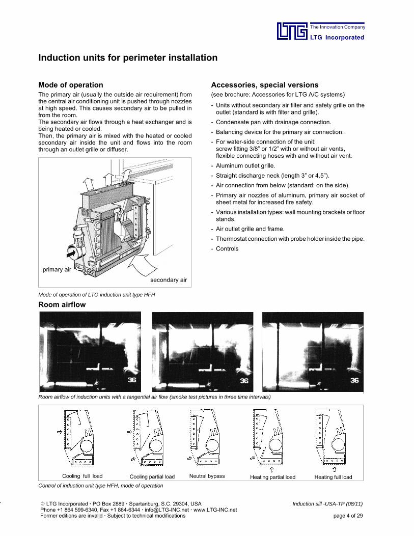
Mode of operationThe primary air (usually the outside air requirement) fromthe central air conditioning unit is pushed through nozzlesat high speed. This causes secondary air to be pulled infrom the room.The secondary air flows through a heat exchanger and isbeing heated or cooled.Then, the primary air is mixed with the heated or cooledsecondary air inside the unit and flows into the roomthrough an outlet grille or diffuser.
secondary air
primary air
Mode of operation of LTG induction unit type HFH
Accessories, special versions(see brochure: Accessories for LTG A/C systems)
- Units without secondary air filter and safety grille on theoutlet (standard is with filter and grille).
- Condensate pan with drainage connection.
- Balancing device for the primary air connection.
- For water-side connection of the unit:screw fitting 3/8” or 1/2” with or without air vents,flexible connecting hoses with and without air vent.
- Aluminum outlet grille.
- Straight discharge neck (length 3” or 4.5”).
- Air connection from below (standard: on the side).
- Primary air nozzles of aluminum, primary air socket ofsheet metal for increased fire safety.
- Various installation types: wall mounting brackets or floorstands.
- Air outlet grille and frame.
- Thermostat connection with probe holder inside the pipe.
- Controls
Room airflow
Room airflow of induction units with a tangential air flow (smoke test pictures in three time intervals)
Cooling full load Cooling partial load Neutral bypass Heating partial load Heating full load
Control of induction unit type HFH, mode of operation
The Innovation Company
LTG Incorporated
E LTG Incorporated · PO Box 2889 · Spartanburg, S.C. 29304, USA Induction sill -USA-TP (08/11)Phone +1 864 599-6340, Fax +1 864-6344 · [email protected] · www.LTG-INC.netFormer editions are invalid · Subject to technical modifications page 5 of 29
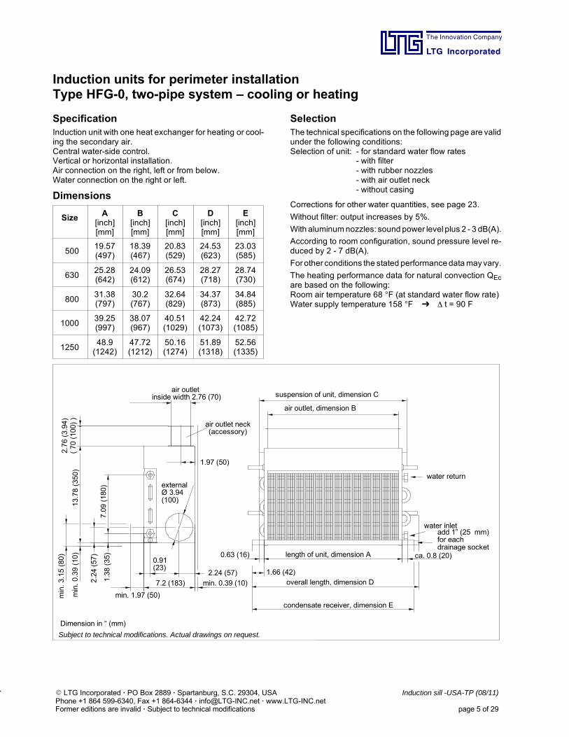
Induction units for perimeter installationType HFG-0, two-pipe system – cooling or heating
SpecificationInduction unit with one heat exchanger for heating or cool-ing the secondary air.Central water-side control.Vertical or horizontal installation.Air connection on the right, left or from below.Water connection on the right or left.
Dimensions
Size A[inch][mm]
B[inch][mm]
C[inch][mm]
D[inch][mm]
E[inch][mm]
50019.57(497)
18.39(467)
20.83(529)
24.53(623)
23.03(585)
63025.28(642)
24.09(612)
26.53(674)
28.27(718)
28.74(730)
80031.38(797)
30.2(767)
32.64(829)
34.37(873)
34.84(885)
100039.25(997)
38.07(967)
40.51(1029)
42.24(1073)
42.72(1085)
125048.9(1242)
47.72(1212)
50.16(1274)
51.89(1318)
52.56(1335)
SelectionThe technical specifications on the following page are validunder the following conditions:Selection of unit: - for standard water flow rates
- with filter- with rubber nozzles- with air outlet neck- without casing
Corrections for other water quantities, see page 23.
Without filter: output increases by 5%.
With aluminumnozzles: sound power level plus 2 - 3 dB(A).
According to room configuration, sound pressure level re-duced by 2 - 7 dB(A).
For other conditions the stated performancedatamayvary.
The heating performance data for natural convection QEcare based on the following:Room air temperature 68 F (at standard water flow rate)Water supply temperature 158 F t = 90 F
13.78(350)
7.2 (183)
7.09(180)
min. 1.97 (50)
2.24 (57)
2.24(57)
min. 0.39 (10)1.38(35)
min.0.39(10)
min.3.15(80)
1.97 (50)
externalØ 3.94(100)
air outletinside width 2.76 (70)
air outlet neck(accessory)
Subject to technical modifications. Actual drawings on request.
water return
water inlet
0.63 (16)
1.66 (42)
ca. 0.8 (20)
overall length, dimension D
length of unit, dimension A
air outlet, dimension B
suspension of unit, dimension C
condensate receiver, dimension E
add 1” (25 mm)for eachdrainage socket
Dimension in “ (mm)
0.91(23)
2.76(3.94)
(70(100))

The Innovation Company
LTG Incorporated
E LTG Incorporated · PO Box 2889 · Spartanburg, S.C. 29304, USA Induction sill -USA-TP (08/11)Phone +1 864 599-6340, Fax +1 864-6344 · [email protected] · www.LTG-INC.netFormer editions are invalid · Subject to technical modifications page 6 of 29
Induction units for perimeter installationType HFG-0, two-pipe system – cooling or heating
Technical data size 500 Technical data size 1000
∆p"H2O
VP[cfm]
LwA[dB(A)]
NC QP/∆tBTU/h·∆t-1
Qc/∆tBTU/h·∆t-1
Qh/∆tBTU/h·∆t-1
0.8182429
262528
19.024.632.2
55.062.566.3
55.062.566.3
1.0182429
282729
19.024.632.2
56.964.470.1
56.964.470.1
1.218242935
29323033
19.024.632.237.9
58.868.273.977.7
58.868.273.977.7
QEc = 1,430 BTU/hm = 24.2 lbspw at woc = 7.2 feet with 0.88 gpmpw at woh = 6.0 feet with 0.88 gpm
∆p"H2O
VP[cfm]
LwA[dB(A)]
NC QP/∆tBTU/h·∆t-1
Qc/∆tBTU/h·∆t-1
Qh/∆tBTU/h·∆t-1
0.8384759
303033
41.751.262.5
113.7125.1134.6
113.7125.1134.6
1.0384759
323134
41.751.262.5
117.5130.8142.2
117.5130.8142.2
1.238475965
33363537
41.751.262.570.1
121.3136.5147.8151.6
121.3136.5147.8151.6
QEc = 2,453 BTU/hm = 42.9 lbspw at woc = 7.2 feet with 1.54 gpmpw at woh = 6.0 feet with 1.54 gpm
Technical data size 630 Technical data size 1250∆p"H2O
VP[cfm]
LwA[dB(A)]
NC QP/∆tBTU/h·∆t-1
Qc/∆tBTU/h·∆t-1
Qh/∆tBTU/h·∆t-1
0.8242935
272628
24.632.237.9
72.079.685.3
72.079.685.3
1.0242935
293129
24.632.237.9
75.885.391.0
75.885.391.0
1.224293541
31333133
24.632.237.943.6
77.787.294.898.6
77.787.294.898.6
QEc = 1,716 BTU/hm = 29.7 lbspw at woc = 7.2 feet with 1.10 gpmpw at woh = 6.0 feet with 1.10 gpm
∆p"H2O
VP[cfm]
LwA[dB(A)]
NC QP/∆tBTU/h·∆t-1
Qc/∆tBTU/h·∆t-1
Qh/∆tBTU/h·∆t-1
0.8475974
323236
51.262.579.6
144.1161.1174.4
144.1161.1174.4
1.0475974
333637
51.262.579.6
149.7168.7182.0
149.7168.7182.0
1.247597488
34373841
51.262.579.694.8
155.4174.4189.5200.9
155.4174.4189.5200.9
QEc = 2,975 BTU/hm = 50.6 lbspw at woc = 7.2 feet with 1.85 gpmpw at woh = 6.0 feet with 1.85 gpm
Technical data size 800
∆p"H2O
VP[cfm]
LwA[dB(A)]
NC QP/∆tBTU/h·∆t-1
Qc/∆tBTU/h·∆t-1
Qh/∆tBTU/h·∆t-1
0.8293847
282831
32.241.751.2
89.1102.4109.9
89.1102.4109.9
1.0293847
303332
32.241.751.2
92.9108.0115.6
92.9108.0115.6
1.229384753
32343335
32.241.751.256.9
96.7111.8119.4125.1
96.7111.8119.4125.1
QEc = 2,023 BTU/hm = 36.3 lbspw at woc = 7.2 feet with 1.32 gpmpw at woh = 6.0 feet with 1.32 gpm
Legend
∆p - static pressure at the primary air socketVP - primary air flow rate (± 10 %)LwA - sound power (± 3 dB)QP - cool. capacity of primary air (fresh air) (± 5 %)Qc - cool. cap., secondary air (heat exch.) (± 5 %)Qh - heating capacity, secondary air (± 5 %)QEc - heating capacity with natural convectionm - weightwoc - standard water flow rate at cooling capacitywoh - standard water flow rate at heating capacity∆t - temperature difference between
air temperature entering the heat exchangerand water supply temperature
∆tP - temperature difference between room airand primary air
∆pw - water-side pressure loss
The Innovation Company
LTG Incorporated
E LTG Incorporated · PO Box 2889 · Spartanburg, S.C. 29304, USA Induction sill -USA-TP (08/11)Phone +1 864 599-6340, Fax +1 864-6344 · [email protected] · www.LTG-INC.netFormer editions are invalid · Subject to technical modifications page 7 of 29
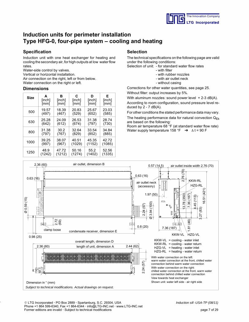
Induction units for perimeter installationType HFG-0, four-pipe system – cooling and heating
SpecificationInduction unit with one heat exchanger for heating andcooling the secondary air, for high outputs at low water flowrates.Water-side control by valves.Vertical or horizontal installation.Air connection on the right, left or from below.Water connection on the right or left.
Dimensions
Size A[inch][mm]
B[inch][mm]
C[inch][mm]
D[inch][mm]
E[inch][mm]
500 19.57(497)
18.39(467)
20.83(529)
25.67(652)
23.03(585)
630 25.28(642)
24.09(612)
26.53(674)
31.38(797)
28.74(730)
800 31.38(797)
30.2(767)
32.64(829)
33.54(852)
34.84(885)
1000 39.25(997)
38.07(967)
40.51(1029)
45.35(1152)
42.72(1085)
1250 48.9(1242)
47.72(1212)
50.16(1274)
55.2(1402)
52.56(1335)
SelectionThe technical specifications on the following page are validunder the following conditions:Selection of unit: - for standard water flow rates
- with filter- with rubber nozzles- with air outlet neck- without casing
Corrections for other water quantities, see page 25.Without filter: output increases by 5%.With aluminum nozzles: sound power level + 2-3 dB(A).According to room configuration, sound pressure level re-duced by 2 - 7 dB(A).
For other conditions the stated performancedatamayvary.
The heating performance data for natural convection QEkare based on the following:Room air temperature 68 F (at standard water flow rate)Water supply temperature 158 F t = 90 F
Subject to technical modifications. Actual drawings on request.
16.51(421)
7.36 (187)
2.36 (60)
0.57 (14.5)
0.98 (25)
KKW-RL
HZG-RL
HZG-VLKKW-VL
length of unit, dimension A
air outlet, dimension B
overall length, dimension D
condensate receiver, dimension E
air outlet inside width 2.76 (70)
2.24(57)
Ø3.94(100)
With water connection on the left:warm water connection at the front, chilled waterconnection behind warm water connectionWith water connection on the right:chilled water connection at the front, warm waterconnection behind chilled water connectionView towards heat exchangerShown unit: water left side - air right side
1.97 (50)
3.27(83)4.45(113)
7.36(187)
13.78(350)
2.76(70)
1.81(46)
2.44 (62)
0.8 (20)
Ø0.59(15)
2.36 (60)
0.63 (16)
2.24(57)
0.63 (16)
2.72
(69)
clamp loose
air outlet neck(accessory)
KKW-VL = cooling - water inletKKW-RL = cooling - water returnHZG-VL = heating - water inletHZG-RL = heating - water return
Dimension in “ (mm)
The Innovation Company
LTG Incorporated
E LTG Incorporated · PO Box 2889 · Spartanburg, S.C. 29304, USA Induction sill -USA-TP (08/11)Phone +1 864 599-6340, Fax +1 864-6344 · [email protected] · www.LTG-INC.netFormer editions are invalid · Subject to technical modifications page 8 of 29
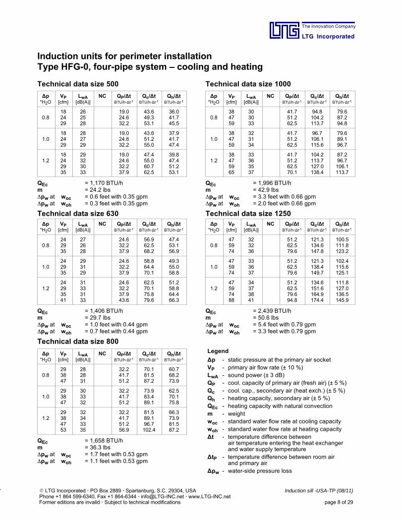
Induction units for perimeter installationType HFG-0, four-pipe system – cooling and heating
Technical data size 500 Technical data size 1000
∆p"H2O
VP[cfm]
LwA[dB(A)]
NC QP/∆tBTU/h·∆t-1
Qc/∆tBTU/h·∆t-1
Qh/∆tBTU/h·∆t-1
0.8182429
262528
19.024.632.2
43.649.353.1
36.041.745.5
1.0182429
282729
19.024.632.2
43.651.255.0
37.941.747.4
1.218242935
29323033
19.024.632.237.9
47.455.060.762.5
39.847.451.253.1
QEc = 1,170 BTU/hm = 24.2 lbspw at woc = 0.6 feet with 0.35 gpmpw at woh = 0.3 feet with 0.35 gpm
∆p"H2O
VP[cfm]
LwA[dB(A)]
NC QP/∆tBTU/h·∆t-1
Qc/∆tBTU/h·∆t-1
Qh/∆tBTU/h·∆t-1
0.8384759
303033
41.751.262.5
94.8104.2113.7
79.687.294.8
1.0384759
323134
41.751.262.5
96.7106.1115.6
79.689.196.7
1.238475965
33363537
41.751.262.570.1
104.2113.7127.0138.4
87.296.7106.1113.7
QEc = 1,996 BTU/hm = 42.9 lbspw at woc = 3.3 feet with 0.66 gpmpw at woh = 2.0 feet with 0.66 gpm
Technical data size 630 Technical data size 1250∆p"H2O
VP[cfm]
LwA[dB(A)]
NC QP/∆tBTU/h·∆t-1
Qc/∆tBTU/h·∆t-1
Qh/∆tBTU/h·∆t-1
0.8242935
272628
24.632.237.9
56.962.568.2
47.453.156.9
1.0242935
293129
24.632.237.9
58.864.470.1
49.355.058.8
1.224293541
31333133
24.632.237.943.6
62.570.175.879.6
51.258.864.466.3
QEc = 1,406 BTU/hm = 29.7 lbspw at woc = 1.0 feet with 0.44 gpmpw at woh = 0.7 feet with 0.44 gpm
∆p"H2O
VP[cfm]
LwA[dB(A)]
NC QP/∆tBTU/h·∆t-1
Qc/∆tBTU/h·∆t-1
Qh/∆tBTU/h·∆t-1
0.8475974
323236
51.262.579.6
121.3134.6147.8
100.5111.8123.2
1.0475974
333637
51.262.579.6
121.3138.4149.7
102.4115.6125.1
1.247597488
34373841
51.262.579.694.8
134.6151.6164.9174.4
111.8127.0136.5145.9
QEc = 2,439 BTU/hm = 50.6 lbspw at woc = 5.4 feet with 0.79 gpmpw at woh = 3.3 feet with 0.79 gpm
Technical data size 800
∆p"H2O
VP[cfm]
LwA[dB(A)]
NC QP/∆tBTU/h·∆t-1
Qc/∆tBTU/h·∆t-1
Qh/∆tBTU/h·∆t-1
0.8293847
282831
32.241.751.2
70.181.587.2
60.768.273.9
1.0293847
303332
32.241.751.2
73.983.489.1
62.570.175.8
1.229384753
32343335
32.241.751.256.9
81.589.196.7102.4
66.373.981.587.2
QEc = 1,658 BTU/hm = 36.3 lbspw at woc = 1.7 feet with 0.53 gpmpw at woh = 1.1 feet with 0.53 gpm
Legend
∆p - static pressure at the primary air socketVP - primary air flow rate (± 10 %)LwA - sound power (± 3 dB)QP - cool. capacity of primary air (fresh air) (± 5 %)Qc - cool. cap., secondary air (heat exch.) (± 5 %)Qh - heating capacity, secondary air (± 5 %)QEc - heating capacity with natural convectionm - weightwoc - standard water flow rate at cooling capacitywoh - standard water flow rate at heating capacity∆t - temperature difference between
air temperature entering the heat exchangerand water supply temperature
∆tP - temperature difference between room airand primary air
∆pw - water-side pressure loss
The Innovation Company
LTG Incorporated
E LTG Incorporated · PO Box 2889 · Spartanburg, S.C. 29304, USA Induction sill -USA-TP (08/11)Phone +1 864 599-6340, Fax +1 864-6344 · [email protected] · www.LTG-INC.netFormer editions are invalid · Subject to technical modifications page 9 of 29
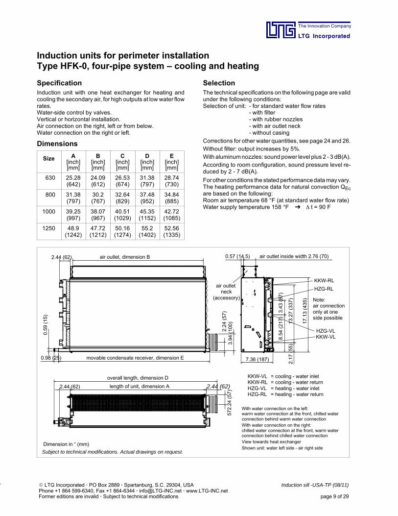
Induction units for perimeter installationType HFK-0, four-pipe system – cooling and heating
SpecificationInduction unit with one heat exchanger for heating andcooling the secondary air, for high outputs at low water flowrates.Water-side control by valves.Vertical or horizontal installation.Air connection on the right, left or from below.Water connection on the right or left.
Dimensions
Size A[inch][mm]
B[inch][mm]
C[inch][mm]
D[inch][mm]
E[inch][mm]
630 25.28(642)
24.09(612)
26.53(674)
31.38(797)
28.74(730)
800 31.38(797)
30.2(767)
32.64(829)
37.48(952)
34.84(885)
1000 39.25(997)
38.07(967)
40.51(1029)
45.35(1152)
42.72(1085)
1250 48.9(1242)
47.72(1212)
50.16(1274)
55.2(1402)
52.56(1335)
SelectionThe technical specifications on the following page are validunder the following conditions:Selection of unit: - for standard water flow rates
- with filter- with rubber nozzles- with air outlet neck- without casing
Corrections for other water quantities, see page 24 and 26.Without filter: output increases by 5%.With aluminumnozzles: sound power level plus 2 - 3 dB(A).According to room configuration, sound pressure level re-duced by 2 - 7 dB(A).
For other conditions the stated performancedatamayvary.The heating performance data for natural convection QEcare based on the following:Room air temperature 68 F (at standard water flow rate)Water supply temperature 158 F t = 90 F
air outlet, dimension B
0.59(15)
0.98 (25) movable condensate receiver, dimension E
2.24(57)
3.94(100)
2.44 (62)
KKW-RL
HZG-RL
HZG-VLKKW-VL
7.36 (187)
2.17(55)
13.27(337)
8.54(217)3.43(87)
0.57 (14.5) air outlet inside width 2.76 (70)
17.13(435)
overall length, dimension D
length of unit, dimension A2.44 (62)
572.24(57)
KKW-VL = cooling - water inletKKW-RL = cooling - water returnHZG-VL = heating - water inletHZG-RL = heating - water return
Dimension in “ (mm)
Subject to technical modifications. Actual drawings on request.
air outletneck
(accessory)
2.44 (62)
Note:air connectiononly at oneside possible
With water connection on the left:warm water connection at the front, chilled waterconnection behind warm water connectionWith water connection on the right:chilled water connection at the front, warm waterconnection behind chilled water connectionView towards heat exchangerShown unit: water left side - air right side
The Innovation Company
LTG Incorporated
E LTG Incorporated · PO Box 2889 · Spartanburg, S.C. 29304, USA Induction sill -USA-TP (08/11)Phone +1 864 599-6340, Fax +1 864-6344 · [email protected] · www.LTG-INC.netFormer editions are invalid · Subject to technical modifications page 10 of 29
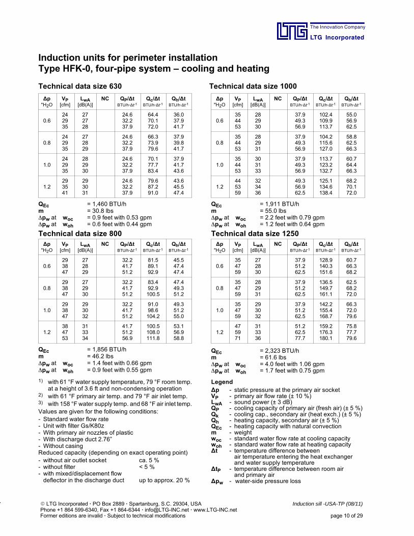
Induction units for perimeter installationType HFK-0, four-pipe system – cooling and heating
Technical data size 630 Technical data size 1000
∆p"H2O
VP[cfm]
LwA[dB(A)]
NC QP/∆tBTU/h·∆t-1
Qc/∆tBTU/h·∆t-1
Qh/∆tBTU/h·∆t-1
0.6242935
272728
24.632.237.9
64.470.172.0
36.037.941.7
0.8242935
272829
24.632.237.9
66.373.979.6
37.939.841.7
1.0242935
282930
24.632.237.9
70.177.783.4
37.941.743.6
1.2293541
293031
24.632.237.9
79.687.291.0
43.645.547.4
QEc = 1,460 BTU/hm = 30.8 lbspw at woc = 0.9 feet with 0.53 gpmpw at woh = 0.6 feet with 0.44 gpm
∆p"H2O
VP[cfm]
LwA[dB(A)]
NC QP/∆tBTU/h·∆t-1
Qc/∆tBTU/h·∆t-1
Qh/∆tBTU/h·∆t-1
0.6354453
282930
37.949.356.9
102.4109.9113.7
55.056.962.5
0.8354453
282931
37.949.356.9
104.2115.6127.0
58.862.566.3
1.0354453
303133
37.949.356.9
113.7123.2132.7
60.764.466.3
1.2445359
323436
49.356.962.5
125.1134.6138.4
68.270.172.0
QEc = 1,911 BTU/hm = 55.0 lbspw at woc = 2.2 feet with 0.79 gpmpw at woh = 1.2 feet with 0.64 gpm
Technical data size 800 Technical data size 1250∆p"H2O
VP[cfm]
LwA[dB(A)]
NC QP/∆tBTU/h·∆t-1
Qc/∆tBTU/h·∆t-1
Qh/∆tBTU/h·∆t-1
0.6293847
272829
32.241.751.2
81.589.192.9
45.547.447.4
0.8293847
272930
32.241.751.2
83.492.9100.5
47.449.351.2
1.0293847
293032
32.241.751.2
91.098.6104.2
49.351.255.0
1.2384753
313334
41.751.256.9
100.5108.0111.8
53.156.958.8
QEc = 1,856 BTU/hm = 46.2 lbspw at woc = 1.4 feet with 0.66 gpmpw at woh = 0.9 feet with 0.55 gpm
∆p"H2O
VP[cfm]
LwA[dB(A)]
NC QP/∆tBTU/h·∆t-1
Qc/∆tBTU/h·∆t-1
Qh/∆tBTU/h·∆t-1
0.6354759
272830
37.951.262.5
128.9140.3151.6
60.766.368.2
0.8354759
282931
37.951.262.5
136.5149.7161.1
62.568.272.0
1.0354759
293032
37.951.262.5
142.2155.4168.7
66.372.079.6
1.2475971
313336
51.262.577.7
159.2176.3180.1
75.877.779.6
QEc = 2,323 BTU/hm = 61.6 lbspw at woc = 4.0 feet with 1.06 gpmpw at woh = 1.7 feet with 0.75 gpm
1) with 61 °F water supply temperature, 79 °F room temp.at a height of 3.6 ft and non-condensing operation
2) with 61 °F primary air temp. and 79 °F air inlet temp.3) with 158 °F water supply temp. and 68 °F air inlet temp.Values are given for the following conditions:- Standard water flow rate- Unit with filter Gs/K80z- With primary air nozzles of plastic- With discharge duct 2.76”- Without casingReduced capacity (depending on exact operating point)- without air outlet socket ca. 5 %- without filter < 5 %- with mixed/displacement flowdeflector in the discharge duct up to approx. 20 %
Legend∆p - static pressure at the primary air socketVP - primary air flow rate (± 10 %)LwA - sound power (± 3 dB)QP - cooling capacity of primary air (fresh air) (± 5 %)Qk - cooling cap., secondary air (heat exch.) (± 5 %)Qh - heating capacity, secondary air (± 5 %)QEc - heating capacity with natural convectionm - weightwoc - standard water flow rate at cooling capacitywoh - standard water flow rate at heating capacity∆t - temperature difference between
air temperature entering the heat exchangerand water supply temperature
∆tP - temperature difference between room airand primary air
∆pw - water-side pressure loss
The Innovation Company
LTG Incorporated
E LTG Incorporated · PO Box 2889 · Spartanburg, S.C. 29304, USA Induction sill -USA-TP (08/11)Phone +1 864 599-6340, Fax +1 864-6344 · [email protected] · www.LTG-INC.netFormer editions are invalid · Subject to technical modifications page 11 of 29
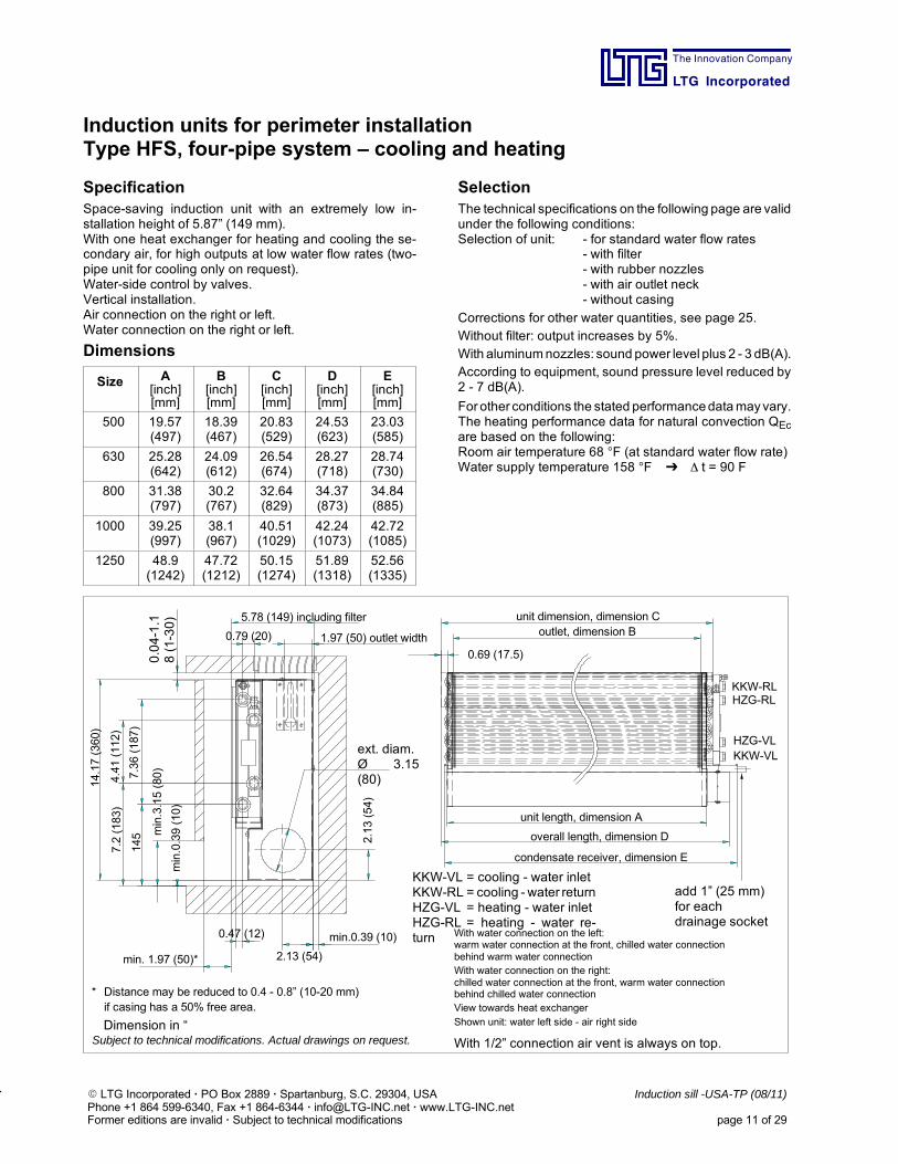
Induction units for perimeter installationType HFS, four-pipe system – cooling and heating
SpecificationSpace-saving induction unit with an extremely low in-stallation height of 5.87” (149 mm).With one heat exchanger for heating and cooling the se-condary air, for high outputs at low water flow rates (two-pipe unit for cooling only on request).Water-side control by valves.Vertical installation.Air connection on the right or left.Water connection on the right or left.
Dimensions
Size A[inch][mm]
B[inch][mm]
C[inch][mm]
D[inch][mm]
E[inch][mm]
500 19.57(497)
18.39(467)
20.83(529)
24.53(623)
23.03(585)
630 25.28(642)
24.09(612)
26.54(674)
28.27(718)
28.74(730)
800 31.38(797)
30.2(767)
32.64(829)
34.37(873)
34.84(885)
1000 39.25(997)
38.1(967)
40.51(1029)
42.24(1073)
42.72(1085)
1250 48.9(1242)
47.72(1212)
50.15(1274)
51.89(1318)
52.56(1335)
SelectionThe technical specifications on the following page are validunder the following conditions:Selection of unit: - for standard water flow rates
- with filter- with rubber nozzles- with air outlet neck- without casing
Corrections for other water quantities, see page 25.Without filter: output increases by 5%.With aluminumnozzles: sound power level plus 2 - 3 dB(A).According to equipment, sound pressure level reduced by2 - 7 dB(A).
For other conditions the stated performancedatamayvary.The heating performance data for natural convection QEcare based on the following:Room air temperature 68 F (at standard water flow rate)Water supply temperature 158 F t = 90 F
add 1” (25 mm)for eachdrainage socket
With water connection on the left:warm water connection at the front, chilled water connectionbehind warm water connectionWith water connection on the right:chilled water connection at the front, warm water connectionbehind chilled water connectionView towards heat exchangerShown unit: water left side - air right side
With 1/2” connection air vent is always on top.
* Distance may be reduced to 0.4 - 0.8” (10-20 mm)if casing has a 50% free area.
KKW-RL
HZG-VL
HZG-RL
KKW-VL
unit length, dimension A
0.69 (17.5)
unit dimension, dimension Coutlet, dimension B
overall length, dimension D
condensate receiver, dimension E
2.13 (54)
2.13(54)
14.17(360)
min. 1.97 (50)*
min.0.39 (10)
min.0.39(10)
min.3.15(80)
0.47 (12)
145
7.36(187)
7.2(183)
4.41(112)
5.78 (149) including filter
1.97 (50) outlet width0.79 (20)
0.04-1.1
8(1-30)
ext. diam.Ø 3.15(80)
KKW-VL = cooling - water inletKKW-RL = cooling - water returnHZG-VL = heating - water inletHZG-RL = heating - water re-turn
Dimension in “(mm)Subject to technical modifications. Actual drawings on request.
The Innovation Company
LTG Incorporated
E LTG Incorporated · PO Box 2889 · Spartanburg, S.C. 29304, USA Induction sill -USA-TP (08/11)Phone +1 864 599-6340, Fax +1 864-6344 · [email protected] · www.LTG-INC.netFormer editions are invalid · Subject to technical modifications page 12 of 29
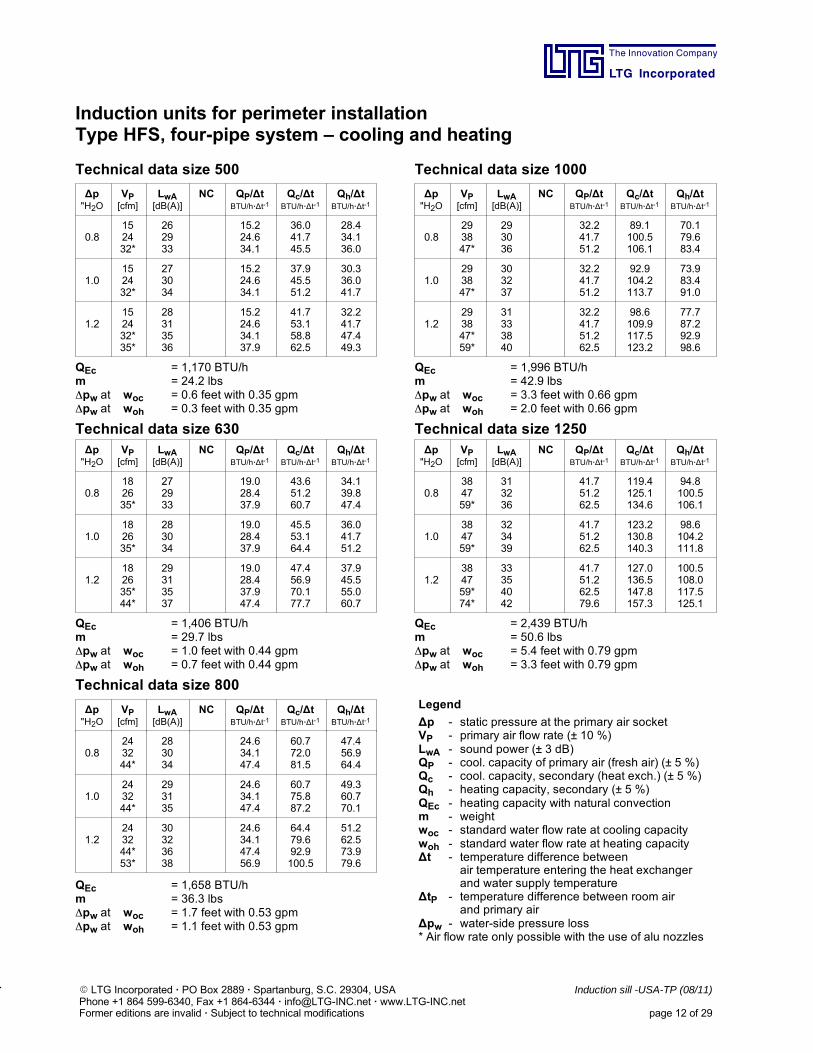
Induction units for perimeter installationType HFS, four-pipe system – cooling and heating
Technical data size 500 Technical data size 1000
∆p"H2O
VP[cfm]
LwA[dB(A)]
NC QP/∆tBTU/h·∆t-1
Qc/∆tBTU/h·∆t-1
Qh/∆tBTU/h·∆t-1
0.8152432*
262933
15.224.634.1
36.041.745.5
28.434.136.0
1.0152432*
273034
15.224.634.1
37.945.551.2
30.336.041.7
1.2152432*35*
28313536
15.224.634.137.9
41.753.158.862.5
32.241.747.449.3
QEc = 1,170 BTU/hm = 24.2 lbspw at woc = 0.6 feet with 0.35 gpmpw at woh = 0.3 feet with 0.35 gpm
∆p"H2O
VP[cfm]
LwA[dB(A)]
NC QP/∆tBTU/h·∆t-1
Qc/∆tBTU/h·∆t-1
Qh/∆tBTU/h·∆t-1
0.8293847*
293036
32.241.751.2
89.1100.5106.1
70.179.683.4
1.0293847*
303237
32.241.751.2
92.9104.2113.7
73.983.491.0
1.2293847*59*
31333840
32.241.751.262.5
98.6109.9117.5123.2
77.787.292.998.6
QEc = 1,996 BTU/hm = 42.9 lbspw at woc = 3.3 feet with 0.66 gpmpw at woh = 2.0 feet with 0.66 gpm
Technical data size 630 Technical data size 1250∆p"H2O
VP[cfm]
LwA[dB(A)]
NC QP/∆tBTU/h·∆t-1
Qc/∆tBTU/h·∆t-1
Qh/∆tBTU/h·∆t-1
0.8182635*
272933
19.028.437.9
43.651.260.7
34.139.847.4
1.0182635*
283034
19.028.437.9
45.553.164.4
36.041.751.2
1.2182635*44*
29313537
19.028.437.947.4
47.456.970.177.7
37.945.555.060.7
QEc = 1,406 BTU/hm = 29.7 lbspw at woc = 1.0 feet with 0.44 gpmpw at woh = 0.7 feet with 0.44 gpm
∆p"H2O
VP[cfm]
LwA[dB(A)]
NC QP/∆tBTU/h·∆t-1
Qc/∆tBTU/h·∆t-1
Qh/∆tBTU/h·∆t-1
0.8384759*
313236
41.751.262.5
119.4125.1134.6
94.8100.5106.1
1.0384759*
323439
41.751.262.5
123.2130.8140.3
98.6104.2111.8
1.2384759*74*
33354042
41.751.262.579.6
127.0136.5147.8157.3
100.5108.0117.5125.1
QEc = 2,439 BTU/hm = 50.6 lbspw at woc = 5.4 feet with 0.79 gpmpw at woh = 3.3 feet with 0.79 gpm
Technical data size 800
∆p"H2O
VP[cfm]
LwA[dB(A)]
NC QP/∆tBTU/h·∆t-1
Qc/∆tBTU/h·∆t-1
Qh/∆tBTU/h·∆t-1
0.8243244*
283034
24.634.147.4
60.772.081.5
47.456.964.4
1.0243244*
293135
24.634.147.4
60.775.887.2
49.360.770.1
1.2243244*53*
30323638
24.634.147.456.9
64.479.692.9100.5
51.262.573.979.6
QEc = 1,658 BTU/hm = 36.3 lbspw at woc = 1.7 feet with 0.53 gpmpw at woh = 1.1 feet with 0.53 gpm
Legend
∆p - static pressure at the primary air socketVP - primary air flow rate (± 10 %)LwA - sound power (± 3 dB)QP - cool. capacity of primary air (fresh air) (± 5 %)Qc - cool. capacity, secondary (heat exch.) (± 5 %)Qh - heating capacity, secondary (± 5 %)QEc - heating capacity with natural convectionm - weightwoc - standard water flow rate at cooling capacitywoh - standard water flow rate at heating capacity∆t - temperature difference between
air temperature entering the heat exchangerand water supply temperature
∆tP - temperature difference between room airand primary air
∆pw - water-side pressure loss* Air flow rate only possible with the use of alu nozzles
The Innovation Company
LTG Incorporated
E LTG Incorporated · PO Box 2889 · Spartanburg, S.C. 29304, USA Induction sill -USA-TP (08/11)Phone +1 864 599-6340, Fax +1 864-6344 · [email protected] · www.LTG-INC.netFormer editions are invalid · Subject to technical modifications page 13 of 29
Induction units for perimeter installationType HFS, four-pipe system – cooling and heating
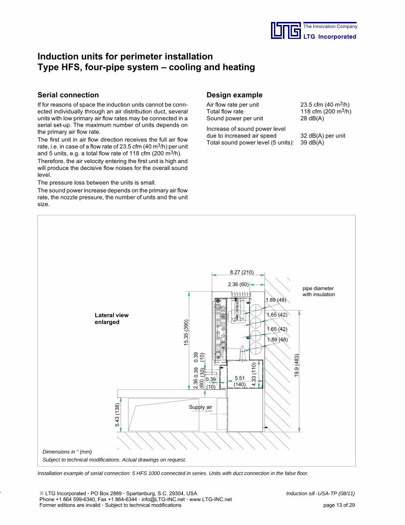
Serial connectionIf for reasons of space the induction units cannot be conn-ected individually through an air distribution duct, severalunits with low primary air flow rates may be connected in aserial set-up. The maximum number of units depends onthe primary air flow rate.The first unit in air flow direction receives the full air flowrate, i.e. in case of a flow rate of 23.5 cfm (40m3/h) per unitand 5 units, e.g. a total flow rate of 118 cfm (200 m3/h).Therefore, the air velocity entering the first unit is high andwill produce the decisive flow noises for the overall soundlevel.The pressure loss between the units is small.The sound power increase depends on the primary air flowrate, the nozzle pressure, the number of units and the unitsize.
Design exampleAir flow rate per unit 23.5 cfm (40 m3/h)Total flow rate 118 cfm (200 m3/h)Sound power per unit 28 dB(A)
Increase of sound power leveldue to increased air speed 32 dB(A) per unitTotal sound power level (5 units): 39 dB(A)
Supply air
8.27 (210)
(60)(10)
(10)
(10)
15.35(390)
5.43(138)
1.65 (42)
(140) 4.33(110)
2.36 (60)
19.9(483)
Lateral viewenlarged
pipe diameterwith insulation
Dimensions in “ (mm)
Subject to technical modifications. Actual drawings on request.
5.51
1.65 (42)
1.89 (48)
1.89 (48)
2.360.39
0.39
0.39
Installation example of serial connection: 5 HFS 1000 connected in series. Units with duct connection in the false floor.
The Innovation Company
LTG Incorporated
E LTG Incorporated · PO Box 2889 · Spartanburg, S.C. 29304, USA Induction sill -USA-TP (08/11)Phone +1 864 599-6340, Fax +1 864-6344 · [email protected] · www.LTG-INC.netFormer editions are invalid · Subject to technical modifications page 14 of 29
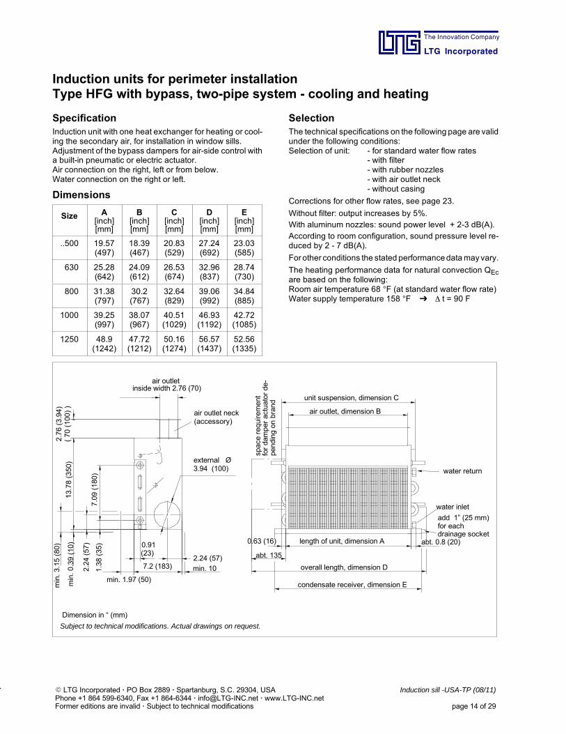
Induction units for perimeter installationType HFG with bypass, two-pipe system - cooling and heating
SpecificationInduction unit with one heat exchanger for heating or cool-ing the secondary air, for installation in window sills.Adjustment of the bypass dampers for air-side control witha built-in pneumatic or electric actuator.Air connection on the right, left or from below.Water connection on the right or left.
Dimensions
Size A[inch][mm]
B[inch][mm]
C[inch][mm]
D[inch][mm]
E[inch][mm]
..500 19.57(497)
18.39(467)
20.83(529)
27.24(692)
23.03(585)
630 25.28(642)
24.09(612)
26.53(674)
32.96(837)
28.74(730)
800 31.38(797)
30.2(767)
32.64(829)
39.06(992)
34.84(885)
1000 39.25(997)
38.07(967)
40.51(1029)
46.93(1192)
42.72(1085)
1250 48.9(1242)
47.72(1212)
50.16(1274)
56.57(1437)
52.56(1335)
SelectionThe technical specifications on the following page are validunder the following conditions:Selection of unit: - for standard water flow rates
- with filter- with rubber nozzles- with air outlet neck- without casing
Corrections for other flow rates, see page 23.
Without filter: output increases by 5%.With aluminum nozzles: sound power level + 2-3 dB(A).According to room configuration, sound pressure level re-duced by 2 - 7 dB(A).
For other conditions the stated performancedatamayvary.
The heating performance data for natural convection QEcare based on the following:Room air temperature 68 F (at standard water flow rate)Water supply temperature 158 F t = 90 F
water return
water inlet
0.63 (16)
abt. 135
abt. 0.8 (20)
spacerequirement
fordamperactuatorde-
pendingonbrand
overall length, dimension D
length of unit, dimension A
air outlet, dimension B
condensate receiver, dimension E
unit suspension, dimension C
add 1” (25 mm)for eachdrainage socket
Subject to technical modifications. Actual drawings on request.
7.2 (183)
(23)
min. 1.97 (50)
2.24 (57)min. 10
2.76(3.94)
(70(100))
external Ø3.94 (100)
air outlet neck(accessory)
Dimension in “ (mm)
0.91
13.78(350)
7.09(180)
2.24(57)
1.38(35)
min.0.39(10)
min.3.15(80)
air outletinside width 2.76 (70)
The Innovation Company
LTG Incorporated
E LTG Incorporated · PO Box 2889 · Spartanburg, S.C. 29304, USA Induction sill -USA-TP (08/11)Phone +1 864 599-6340, Fax +1 864-6344 · [email protected] · www.LTG-INC.netFormer editions are invalid · Subject to technical modifications page 15 of 29
Induction units for perimeter installationType HFG with bypass, two-pipe system – cooling or heating
Technical data size 500 Technical data size 1000
∆p"H2O
VP[cfm]
LwA[dB(A)]
NC QP/∆tBTU/h·∆t-1
Qc/∆tBTU/h·∆t-1
Qh/∆tBTU/h·∆t-1
0.8182429
262528
19.024.632.2
53.162.566.3
53.162.566.3
1.0182429
282729
19.024.632.2
56.964.470.1
56.964.470.1
1.218242935
29323033
19.024.632.237.9
58.868.273.977.7
58.868.273.977.7
QEc = 812 BTU/hm = 24.2 lbspw at woc = 7.2 feet with 0.88 gpmpw at woh = 6.0 feet with 0.88 gpm
∆p"H2O
VP[cfm]
LwA[dB(A)]
NC QP/∆tBTU/h·∆t-1
Qc/∆tBTU/h·∆t-1
Qh/∆tBTU/h·∆t-1
0.8384759
303033
41.751.262.5
113.7125.1134.6
113.7125.1134.6
1.0384759
323134
41.751.262.5
117.5132.7142.2
117.5132.7142.2
1.238475965
33363537
41.751.262.570.1
121.3136.5147.8151.6
121.3136.5147.8151.6
QEc = 1,375 BTU/hm = 42.9 lbspw at woc = 7.2 feet with 1.54 gpmpw at woh = 6.0 feet with 1.54 gpm
Technical data size 630 Technical data size 1250∆p"H2O
VP[cfm]
LwA[dB(A)]
NC QP/∆tBTU/h·∆t-1
Qc/∆tBTU/h·∆t-1
Qh/∆tBTU/h·∆t-1
0.8242935
272628
24.632.237.9
72.079.685.3
72.079.685.3
1.0242935
293129
24.632.237.9
73.985.391.0
73.985.391.0
1.224293541
31333133
24.632.237.943.6
77.787.294.898.6
77.787.294.898.6
QEc = 972 BTU/hm = 29.7 lbspw at woc = 7.2 feet with 1.10 gpmpw at woh = 6.0 feet with 1.10 gpm
∆p"H2O
VP[cfm]
LwA[dB(A)]
NC QP/∆tBTU/h·∆t-1
Qc/∆tBTU/h·∆t-1
Qh/∆tBTU/h·∆t-1
0.8475974
323236
51.262.579.6
144.1161.1174.4
144.1161.1174.4
1.0475974
333637
51.262.579.6
149.7168.7182.0
149.7168.7182.0
1.247597488
34373841
51.262.579.694.8
155.4174.4189.5200.9
155.4174.4189.5200.9
QEc = 1,665 BTU/hm = 50.6 lbspw at woc = 7.2 feet with 1.85 gpmpw at woh = 6.0 feet with 1.85 gpm
Technical data size 800
∆p"H2O
VP[cfm]
LwA[dB(A)]
NC QP/∆tBTU/h·∆t-1
Qc/∆tBTU/h·∆t-1
Qh/∆tBTU/h·∆t-1
0.8293847
282831
32.241.751.2
89.1102.4109.9
89.1102.4109.9
1.0293847
303332
32.241.751.2
92.9108.0115.6
92.9108.0115.6
1.229384753
32343335
32.241.751.256.9
96.7111.8119.4125.1
96.7111.8119.4125.1
QEc = 1,140 BTU/hm = 36.3 lbspw at woc = 7.2 feet with 1.32 gpmpw at woh = 6.0 feet with 1.32 gpm
Legend
∆p - static pressure at the primary air socketVP - primary air flow rate (± 10 %)LwA - sound power (± 3 dB)QP - cool. capacity of primary air (fresh air) (± 5 %)Qc - cool. cap., secondary air (heat exch.) (± 5 %)Qh - heating capacity, secondary air (± 5 %)QEc - heating capacity with natural convectionm - weightwoc - standard water flow rate at cooling capacitywoh - standard water flow rate at heating capacity∆t - temperature difference between
air temperature entering the heat exchangerand water supply temperature
∆tP - temperature difference between room airand primary air
∆pw - water-side pressure loss
The Innovation Company
LTG Incorporated
E LTG Incorporated · PO Box 2889 · Spartanburg, S.C. 29304, USA Induction sill -USA-TP (08/11)Phone +1 864 599-6340, Fax +1 864-6344 · [email protected] · www.LTG-INC.netFormer editions are invalid · Subject to technical modifications page 16 of 29
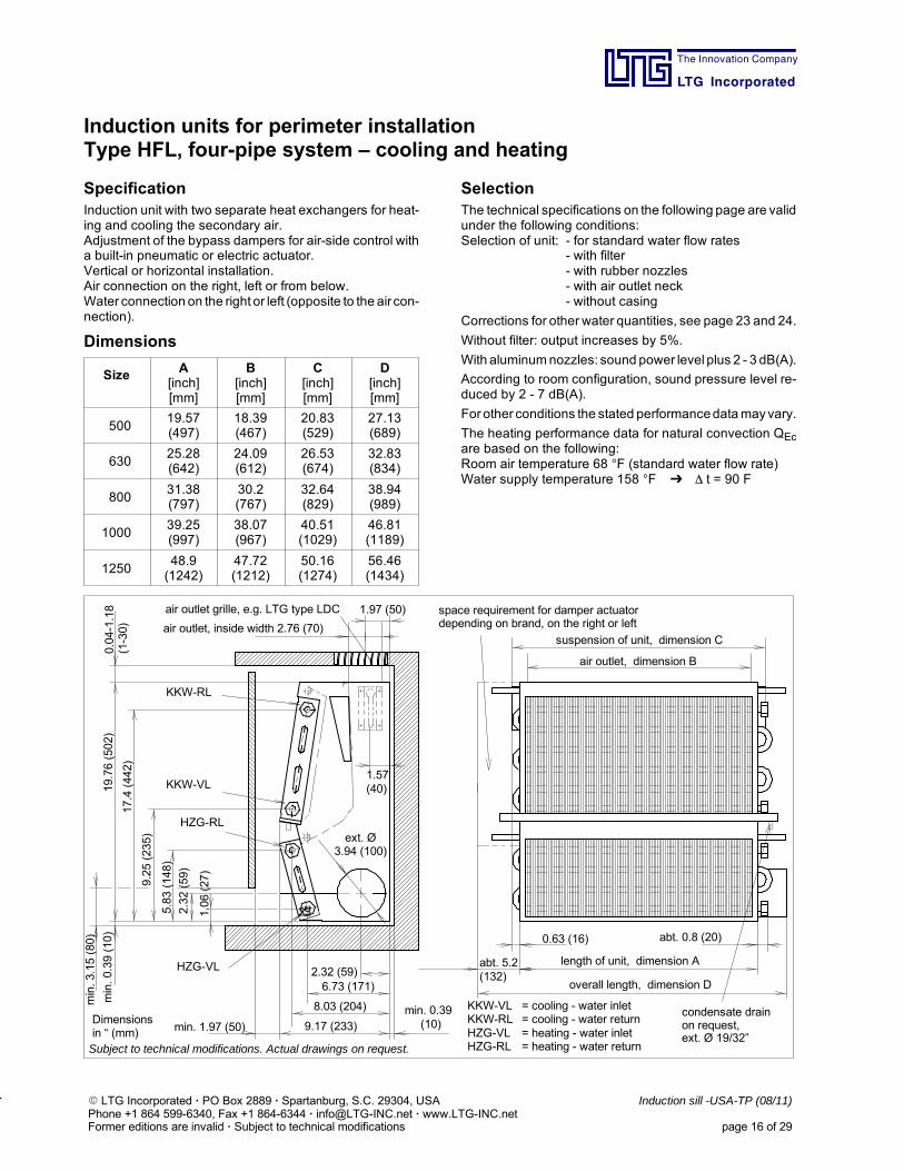
Induction units for perimeter installationType HFL, four-pipe system – cooling and heating
SpecificationInduction unit with two separate heat exchangers for heat-ing and cooling the secondary air.Adjustment of the bypass dampers for air-side control witha built-in pneumatic or electric actuator.Vertical or horizontal installation.Air connection on the right, left or from below.Water connection on the right or left (opposite to the aircon-nection).
Dimensions
Size A[inch][mm]
B[inch][mm]
C[inch][mm]
D[inch][mm]
50019.57(497)
18.39(467)
20.83(529)
27.13(689)
63025.28(642)
24.09(612)
26.53(674)
32.83(834)
80031.38(797)
30.2(767)
32.64(829)
38.94(989)
100039.25(997)
38.07(967)
40.51(1029)
46.81(1189)
125048.9(1242)
47.72(1212)
50.16(1274)
56.46(1434)
SelectionThe technical specifications on the following page are validunder the following conditions:Selection of unit: - for standard water flow rates
- with filter- with rubber nozzles- with air outlet neck- without casing
Corrections for other water quantities, see page 23 and 24.
Without filter: output increases by 5%.
With aluminumnozzles: sound power level plus 2 - 3 dB(A).
According to room configuration, sound pressure level re-duced by 2 - 7 dB(A).
For other conditions the stated performancedatamayvary.
The heating performance data for natural convection QEcare based on the following:Room air temperature 68 F (standard water flow rate)Water supply temperature 158 F t = 90 F
abt. 5.2(132)
abt. 0.8 (20)
min. 0.39(10)min. 1.97 (50)
23
2.32 (59)
9.17 (233)
KKW-RL
min.0.39(10)
min.3.15(80)
19.76(502)
17.4(442)
2.32(59)
1.06(27)
8.03 (204)
6.73 (171)
1.57(40)
1.97 (50)
9.25(235)
5.83(148)
HZG-RL
KKW-VL
0.63 (16)
HZG-VL
KKW-VL = cooling - water inletKKW-RL = cooling - water returnHZG-VL = heating - water inletHZG-RL = heating - water return
space requirement for damper actuatordepending on brand, on the right or left
air outlet grille, e.g. LTG type LDC
air outlet, inside width 2.76 (70)suspension of unit, dimension C
air outlet, dimension B
length of unit, dimension A
overall length, dimension D
condensate drainon request,ext. Ø 19/32”
Subject to technical modifications. Actual drawings on request.
ext. Ø3.94 (100)
Dimensionsin “ (mm)
0.04-1.18
(1-30)

The Innovation Company
LTG Incorporated
E LTG Incorporated · PO Box 2889 · Spartanburg, S.C. 29304, USA Induction sill -USA-TP (08/11)Phone +1 864 599-6340, Fax +1 864-6344 · [email protected] · www.LTG-INC.netFormer editions are invalid · Subject to technical modifications page 17 of 29
Induction units for perimeter installationType HFL, four-pipe system – cooling and heating
Technical data size 500 Technical data size 1000
∆p"H2O
VP[cfm]
LwA[dB(A)]
NC QP/∆tBTU/h·∆t-1
Qc/∆tBTU/h·∆t-1
Qh/∆tBTU/h·∆t-1
0.8182429
262528
19.024.632.2
45.551.255.0
34.137.941.7
1.0182429
282729
19.024.632.2
49.355.060.7
36.039.843.6
1.218242935
29323033
19.024.632.237.9
51.256.962.566.3
36.039.843.647.4
QEc = 856 BTU/hm = 33.0 lbspw at woc = 7.2 feet with 0.88 gpmpw at woh = 0.5 feet with 0.31 gpm
∆p"H2O
VP[cfm]
LwA[dB(A)]
NC QP/∆tBTU/h·∆t-1
Qc/∆tBTU/h·∆t-1
Qh/∆tBTU/h·∆t-1
0.8384759
303033
41.751.262.5
94.8102.4113.7
72.077.783.4
1.0384759
323134
41.751.262.5
100.5109.9119.4
73.979.687.2
1.238475965
33363537
41.751.262.570.1
106.1115.6127.0130.8
75.881.589.191.0
QEc = 1,433 BTU/hm = 52.8 lbspw at woc = 7.2 feet with 1.54 gpmpw at woh = 0.5 feet with 0.48 gpm
Technical data size 630 Technical data size 1250∆p"H2O
VP[cfm]
LwA[dB(A)]
NC QP/∆tBTU/h·∆t-1
Qc/∆tBTU/h·∆t-1
Qh/∆tBTU/h·∆t-1
0.8242935
272628
24.632.237.9
60.766.372.0
45.549.353.1
1.0242935
293129
24.632.237.9
64.472.077.7
47.451.255.0
1.224293541
31333133
24.632.237.943.6
68.273.981.585.3
49.353.155.058.8
QEc = 1,013 BTU/hm = 37.4 lbspw at woc = 7.2 feet with 1.10 gpmpw at woh = 0.5 feet with 0.35 gpm
∆p"H2O
VP[cfm]
LwA[dB(A)]
NC QP/∆tBTU/h·∆t-1
Qc/∆tBTU/h·∆t-1
Qh/∆tBTU/h·∆t-1
0.8475974
323236
51.262.579.6
121.3132.7145.9
91.098.6108.0
1.0475974
333637
51.262.579.6
128.9142.2155.4
94.8100.5109.9
1.247597488
34373841
51.262.579.694.8
136.5147.8164.9172.5
96.7106.1111.8119.4
QEc = 1,726 BTU/hm = 63.8 lbspw at woc = 7.2 feet with 1.85 gpmpw at woh = 0.5 feet with 0.67 gpm
Technical data size 800
∆p"H2O
VP[cfm]
LwA[dB(A)]
NC QP/∆tBTU/h·∆t-1
Qc/∆tBTU/h·∆t-1
Qh/∆tBTU/h·∆t-1
0.8293847
282831
32.241.751.2
75.885.391.0
56.962.568.2
1.0293847
303332
32.241.751.2
81.591.098.6
58.864.470.1
1.229384753
32343335
32.241.751.256.9
85.394.8104.2108.0
60.766.370.173.9
QEc = 1,187 BTU/hm = 44.0 lbspw at woc = 7.2 feet with 1.32 gpmpw at woh = 0.5 feet with 0.42 gpm
Legend
∆p - static pressure at the primary air socketVP - primary air flow rate (± 10 %)LwA - sound power (± 3 dB)QP - cool. capacity of primary air (fresh air) (± 5 %)Qc - cool. cap., secondary air (heat exch.) (± 5 %)Qh - heating capacity, secondary air (± 5 %)QEc - heating capacity with natural convectionm - weightwoc - standard water flow rate at cooling capacitywoh - standard water flow rate at heating capacity∆t - temperature difference between
air temperature entering the heat exchangerand water supply temperature
∆tP - temperature difference between room airand primary air
∆pw - water-side pressure loss
The Innovation Company
LTG Incorporated
E LTG Incorporated · PO Box 2889 · Spartanburg, S.C. 29304, USA Induction sill -USA-TP (08/11)Phone +1 864 599-6340, Fax +1 864-6344 · [email protected] · www.LTG-INC.netFormer editions are invalid · Subject to technical modifications page 18 of 29
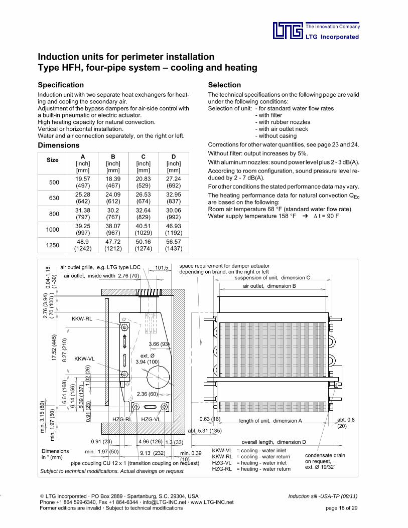
Induction units for perimeter installationType HFH, four-pipe system – cooling and heating
SpecificationInduction unit with two separate heat exchangers for heat-ing and cooling the secondary air.Adjustment of the bypass dampers for air-side control witha built-in pneumatic or electric actuator.High heating capacity for natural convection.Vertical or horizontal installation.Water and air connection separately, on the right or left.
Dimensions
Size A[inch][mm]
B[inch][mm]
C[inch][mm]
D[inch][mm]
50019.57(497)
18.39(467)
20.83(529)
27.24(692)
63025.28(642)
24.09(612)
26.53(674)
32.95(837)
80031.38(797)
30.2(767)
32.64(829)
30.06(992)
100039.25(997)
38.07(967)
40.51(1029)
46.93(1192)
125048.9(1242)
47.72(1212)
50.16(1274)
56.57(1437)
SelectionThe technical specifications on the following page are validunder the following conditions:Selection of unit: - for standard water flow rates
- with filter- with rubber nozzles- with air outlet neck- without casing
Corrections for other water quantities, see page 23 and 24.
Without filter: output increases by 5%.
With aluminumnozzles: sound power level plus 2 - 3 dB(A).
According to room configuration, sound pressure level re-duced by 2 - 7 dB(A).
For other conditions the stated performancedatamayvary.
The heating performance data for natural convection QEcare based on the following:Room air temperature 68 F (standard water flow rate)Water supply temperature 158 F t = 90 F
abt. 5.31 (135)
abt. 0.8(20)
min. 0.39(10)
min. 1.97 (50)
1.3 (33)
9.13 (232)
HZG-VL
KKW-RL
min.1.97(50)
min.3.15(80)
17.52(445)
8.27(210)
1.02(26)
0.91(23)
4.96 (126)
3.66 (93)
101,5
6.61(168)
6.14(156)
HZG-RL
KKW-VL
0.63 (16)
0.91 (23)
5.39(137)
2.36 (60)
air outlet grille, e.g. LTG type LDC
air outlet, inside width 2.76 (70)
space requirement for damper actuatordepending on brand, on the right or left
suspension of unit, dimension C
air outlet, dimension B
length of unit, dimension A
overall length, dimension D
pipe coupling CU 12 x 1 (transition coupling on request)
KKW-VL = cooling - water inletKKW-RL = cooling - water returnHZG-VL = heating - water inletHZG-RL = heating - water returnSubject to technical modifications. Actual drawings on request.
condensate drainon request,ext. Ø 19/32”
Dimensionsin “ (mm)
0.04-1.18
(1-30)
ext. Ø3.94 (100)
2.76(3.94)
(70(100))
The Innovation Company
LTG Incorporated
E LTG Incorporated · PO Box 2889 · Spartanburg, S.C. 29304, USA Induction sill -USA-TP (08/11)Phone +1 864 599-6340, Fax +1 864-6344 · [email protected] · www.LTG-INC.netFormer editions are invalid · Subject to technical modifications page 19 of 29
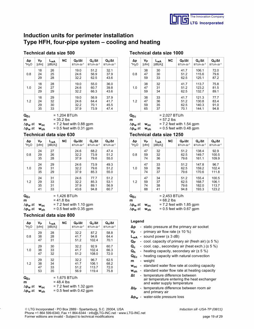
Induction units for perimeter installationType HFH, four-pipe system – cooling and heating
Technical data size 500 Technical data size 1000
∆p"H2O
VP[cfm]
LwA[dB(A)]
NC QP/∆tBTU/h·∆t-1
Qc/∆tBTU/h·∆t-1
Qh/∆tBTU/h·∆t-1
0.8182429
262528
19.024.632.2
51.256.962.5
32.137.943.6
1.0182429
282729
19.024.632.2
55.060.766.3
36.039.843.6
1.218242935
29323033
19.024.632.237.9
56.964.470.173.9
37.941.745.547.4
QEc = 1,204 BTU/hm = 35.2 lbspw at woc = 7.2 feet with 0.88 gpmpw at woh = 0.5 feet with 0.31 gpm
∆p"H2O
VP[cfm]
LwA[dB(A)]
NC QP/∆tBTU/h·∆t-1
Qc/∆tBTU/h·∆t-1
Qh/∆tBTU/h·∆t-1
0.8384759
303033
41.751.262.5
106.1115.6125.1
72.079.687.2
1.0384759
323134
41.751.262.5
113.7123.2132.7
75.881.589.1
1.238475965
33363537
41.751.262.570.1
121.3130.8140.3144.1
77.783.491.094.8
QEc = 2,027 BTU/hm = 57.2 lbspw at woc = 7.2 feet with 1.54 gpmpw at woh = 0.5 feet with 0.48 gpm
Technical data size 630 Technical data size 1250∆p"H2O
VP[cfm]
LwA[dB(A)]
NC QP/∆tBTU/h·∆t-1
Qc/∆tBTU/h·∆t-1
Qh/∆tBTU/h·∆t-1
0.8242935
272628
24.632.237.9
68.273.979.6
47.451.255.0
1.0242935
293129
24.632.237.9
73.979.685.3
49.351.255.0
1.224293541
31333133
24.632.237.943.6
77.785.389.194.8
51.253.156.960.7
QEc = 1,426 BTU/hm = 41.8 lbspw at woc = 7.2 feet with 1.10 gpmpw at woh = 0.5 feet with 0.35 gpm
∆p"H2O
VP[cfm]
LwA[dB(A)]
NC QP/∆tBTU/h·∆t-1
Qc/∆tBTU/h·∆t-1
Qh/∆tBTU/h·∆t-1
0.8475974
323236
51.262.579.6
138.4149.7161.1
92.9100.5109.9
1.0475974
333637
51.262.579.6
147.8159.2170.6
96.7102.4111.8
1.247597488
34373841
51.262.579.694.8
155.4168.7182.0193.3
100.5106.1113.7123.2
QEc = 2,453 BTU/hm = 68.2 lbspw at woc = 7.2 feet with 1.85 gpmpw at woh = 0.5 feet with 0.67 gpm
Technical data size 800
∆p"H2O
VP[cfm]
LwA[dB(A)]
NC QP/∆tBTU/h·∆t-1
Qc/∆tBTU/h·∆t-1
Qh/∆tBTU/h·∆t-1
0.8293847
282831
32.241.751.2
87.294.8102.4
58.864.470.1
1.0293847
303332
32.241.751.2
92.9102.4108.0
60.766.372.0
1.229384753
32343335
32.241.751.256.9
96.7106.1113.7119.4
62.568.272.075.8
QEc = 1,675 BTU/hm = 48.4 lbspw at woc = 7.2 feet with 1.32 gpmpw at woh = 0.5 feet with 0.42 gpm
Legend
∆p - static pressure at the primary air socketVP - primary air flow rate (± 10 %)LwA - sound power (± 3 dB)QP - cool. capacity of primary air (fresh air) (± 5 %)Qc - cool. cap., secondary air (heat exch.) (± 5 %)Qh - heating capacity, secondary air (± 5 %)QEc - heating capacity with natural convectionm - weightwoc - standard water flow rate at cooling capacitywoh - standard water flow rate at heating capacity∆t - temperature difference between
air temperature entering the heat exchangerand water supply temperature
∆tP - temperature difference between room airand primary air
∆pw - water-side pressure loss
The Innovation Company
LTG Incorporated
E LTG Incorporated · PO Box 2889 · Spartanburg, S.C. 29304, USA Induction sill -USA-TP (08/11)Phone +1 864 599-6340, Fax +1 864-6344 · [email protected] · www.LTG-INC.netFormer editions are invalid · Subject to technical modifications page 20 of 29
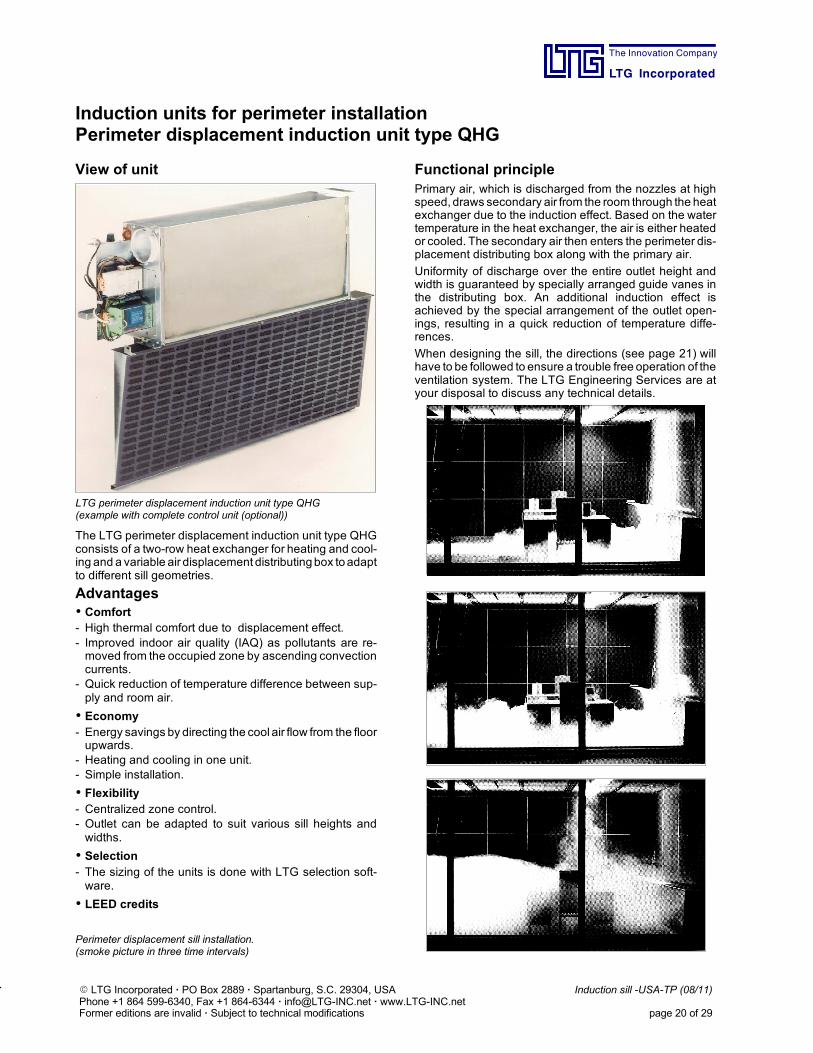
Induction units for perimeter installationPerimeter displacement induction unit type QHG
View of unit
LTG perimeter displacement induction unit type QHG(example with complete control unit (optional))
The LTG perimeter displacement induction unit type QHGconsists of a two-row heat exchanger for heating and cool-ing and a variable air displacement distributingbox toadaptto different sill geometries.
Advantages Comfort- High thermal comfort due to displacement effect.- Improved indoor air quality (IAQ) as pollutants are re-moved from the occupied zone by ascending convectioncurrents.
- Quick reduction of temperature difference between sup-ply and room air.
Economy- Energy savings by directing the cool air flow from the floorupwards.
- Heating and cooling in one unit.- Simple installation.
Flexibility- Centralized zone control.- Outlet can be adapted to suit various sill heights andwidths.
Selection- The sizing of the units is done with LTG selection soft-ware.
LEED credits
Perimeter displacement sill installation.(smoke picture in three time intervals)
Functional principlePrimary air, which is discharged from the nozzles at highspeed, draws secondary air from the room through the heatexchanger due to the induction effect. Based on the watertemperature in the heat exchanger, the air is either heatedor cooled. The secondary air then enters the perimeter dis-placement distributing box along with the primary air.
Uniformity of discharge over the entire outlet height andwidth is guaranteed by specially arranged guide vanes inthe distributing box. An additional induction effect isachieved by the special arrangement of the outlet open-ings, resulting in a quick reduction of temperature diffe-rences.
When designing the sill, the directions (see page 21) willhave to be followed to ensure a trouble free operation of theventilation system. The LTG Engineering Services are atyour disposal to discuss any technical details.
The Innovation Company
LTG Incorporated
E LTG Incorporated · PO Box 2889 · Spartanburg, S.C. 29304, USA Induction sill -USA-TP (08/11)Phone +1 864 599-6340, Fax +1 864-6344 · [email protected] · www.LTG-INC.netFormer editions are invalid · Subject to technical modifications page 21 of 29
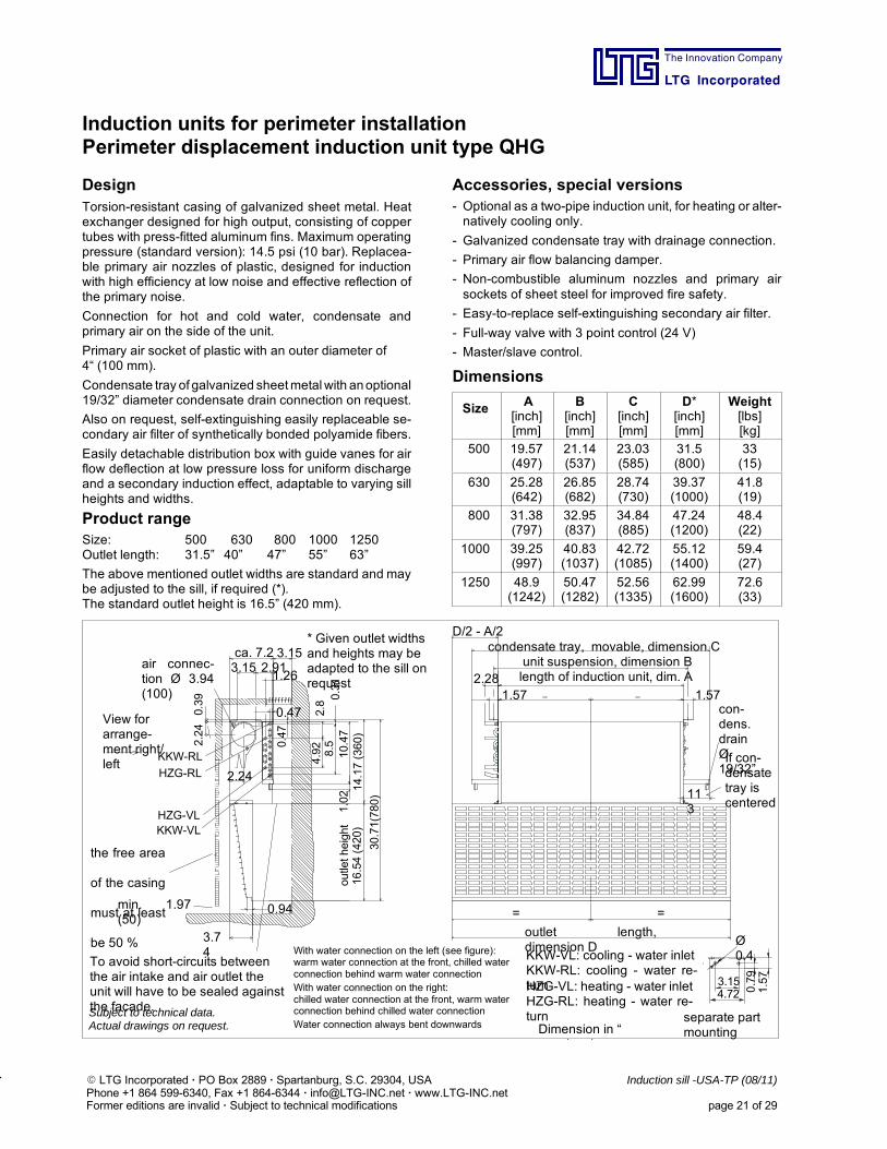
Induction units for perimeter installationPerimeter displacement induction unit type QHG
DesignTorsion-resistant casing of galvanized sheet metal. Heatexchanger designed for high output, consisting of coppertubes with press-fitted aluminum fins. Maximum operatingpressure (standard version): 14.5 psi (10 bar). Replacea-ble primary air nozzles of plastic, designed for inductionwith high efficiency at low noise and effective reflection ofthe primary noise.
Connection for hot and cold water, condensate andprimary air on the side of the unit.
Primary air socket of plastic with an outer diameter of4“ (100 mm).
Condensate tray of galvanized sheetmetalwith anoptional19/32” diameter condensate drain connection on request.
Also on request, self-extinguishing easily replaceable se-condary air filter of synthetically bonded polyamide fibers.
Easily detachable distribution box with guide vanes for airflow deflection at low pressure loss for uniform dischargeand a secondary induction effect, adaptable to varying sillheights and widths.
Product rangeSize: 500 630 800 1000 1250Outlet length: 31.5” 40” 47” 55” 63”
The above mentioned outlet widths are standard and maybe adjusted to the sill, if required (*).The standard outlet height is 16.5” (420 mm).
Accessories, special versions- Optional as a two-pipe induction unit, for heating or alter-natively cooling only.
- Galvanized condensate tray with drainage connection.
- Primary air flow balancing damper.
- Non-combustible aluminum nozzles and primary airsockets of sheet steel for improved fire safety.
- Easy-to-replace self-extinguishing secondary air filter.
- Full-way valve with 3 point control (24 V)
- Master/slave control.
Dimensions
Size A[inch][mm]
B[inch][mm]
C[inch][mm]
D*[inch][mm]
Weight[lbs][kg]
500 19.57(497)
21.14(537)
23.03(585)
31.5(800)
33(15)
630 25.28(642)
26.85(682)
28.74(730)
39.37(1000)
41.8(19)
800 31.38(797)
32.95(837)
34.84(885)
47.24(1200)
48.4(22)
1000 39.25(997)
40.83(1037)
42.72(1085)
55.12(1400)
59.4(27)
1250 48.9(1242)
50.47(1282)
52.56(1335)
62.99(1600)
72.6(33)
air connec-tion Ø 3.94(100)
Subject to technical data.Actual drawings on request.
HZG-VL: heating - water inletHZG-RL: heating - water re-turn
KKW-VL: cooling - water inletKKW-RL: cooling - water re-turn
HZG-VLKKW-VL
HZG-RL
KKW-RL
the free area
of the casing
must at least
be 50 % 3.74
ca. 7.2 3.15
0.94
3.15 2.91
=
0.47
2.24
1.26
0.39
14.17(360)
2.24
outletheight
30.71(780)
2.8
1.02
4.92 8.5
10.47
0.31
0.47
=
113
1.57
D/2 - A/2
2.281.57
4.723.15
0.79
1.57
Ø0.4
View forarrange-ment right/left
To avoid short-circuits betweenthe air intake and air outlet theunit will have to be sealed againstthe facade.
min. 1.97(50)
con-dens.drainØ19/32”If con-densatetray iscentered
outlet length,dimension D
condensate tray, movable, dimension Cunit suspension, dimension Blength of induction unit, dim. A
* Given outlet widthsand heights may beadapted to the sill onrequest
separate partmounting
With water connection on the left (see figure):warm water connection at the front, chilled waterconnection behind warm water connectionWith water connection on the right:chilled water connection at the front, warm waterconnection behind chilled water connectionWater connection always bent downwards Dimension in “
( )
16.54(420)
The Innovation Company
LTG Incorporated
E LTG Incorporated · PO Box 2889 · Spartanburg, S.C. 29304, USA Induction sill -USA-TP (08/11)Phone +1 864 599-6340, Fax +1 864-6344 · [email protected] · www.LTG-INC.netFormer editions are invalid · Subject to technical modifications page 22 of 29
Induction units for perimeter installationPerimeter displacement induction unit type QHG
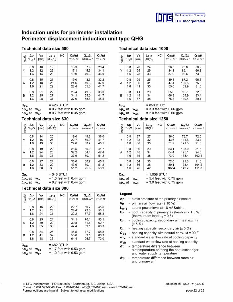
Technical data size 500 Technical data size 1000
nozzle ∆p
"H2OVP[cfm]
LA18[dB(A)]
NC QP/∆tBTU/h·∆t-1
Qc/∆tBTU/h·∆t-1
Qh/∆tBTU/h·∆t-1
Y0.81.21.6
101214
192528
13.317.119.0
37.945.549.3
28.434.136.0
A0.81.21.6
151821
212529
19.024.628.4
43.649.355.0
32.237.941.7
B0.81.21.6
212528
222731
28.434.137.9
49.355.058.8
36.041.745.5
QEc = 426 BTU/hpw at woc = 0.7 feet with 0.35 gpmpw at woh = 0.7 feet with 0.35 gpm
nozzle ∆p
"H2OVP[cfm]
LA18[dB(A)]
NC QP/∆tBTU/h·∆t-1
Qc/∆tBTU/h·∆t-1
Qh/∆tBTU/h·∆t-1
Y0.81.21.6
202528
242933
26.534.137.9
75.889.198.6
56.966.373.9
A0.81.21.6
293641
263135
39.847.455.0
87.2100.5109.9
66.375.881.5
B0.81.21.6
414957
293438
55.066.375.8
96.7109.9119.4
72.083.489.1
QEc = 853 BTU/hpw at woc = 3.3 feet with 0.66 gpmpw at woh = 2.0 feet with 0.66 gpm
Technical data size 630 Technical data size 1250
nozzle ∆p
"H2OVP[cfm]
LA18[dB(A)]
NC QP/∆tBTU/h·∆t-1
Qc/∆tBTU/h·∆t-1
Qh/∆tBTU/h·∆t-1
Y0.81.21.6
141619
202630
19.022.724.6
49.356.960.7
36.041.745.5
A0.81.21.6
192428
222831
26.532.237.9
55.064.470.1
41.747.451.2
B0.81.21.6
273338
242933
36.043.651.2
60.770.175.8
45.551.256.9
QEc = 546 BTU/hpw at woc = 1.0 feet with 0.44 gpmpw at woh = 0.7 feet with 0.44 gpm
nozzle ∆p
"H2OVP[cfm]
LA18[dB(A)]
NC QP/∆tBTU/h·∆t-1
Qc/∆tBTU/h·∆t-1
Qh/∆tBTU/h·∆t-1
Y0.81.21.6
273338
273235
36.043.651.2
76.7111.8121.3
72.083.491.0
A0.81.21.6
394855
293438
53.164.473.9
108.0125.1138.4
81.594.8102.4
B0.81.21.6
546676
333842
72.089.1102.4
121.3138.4149.7
91.0104.2111.8
QEc = 1,058 BTU/hpw at woc = 5.4 feet with 0.75 gpmpw at woh = 3.0 feet with 0.75 gpm
Technical data size 800
nozzle ∆p
"H2OVP[cfm]
LA18[dB(A)]
NC QP/∆tBTU/h·∆t-1
Qc/∆tBTU/h·∆t-1
Qh/∆tBTU/h·∆t-1
Y0.81.21.6
162124
222831
22.728.432.2
60.772.077.7
45.553.158.8
A0.81.21.6
253035
242933
34.139.847.4
70.181.589.1
53.160.766.3
B0.81.21.6
344148
263235
45.555.064.4
77.789.196.7
58.866.372.0
QEc = 682 BTU/hpw at woc = 1.7 feet with 0.53 gpmpw at woh = 1.0 feet with 0.53 gpm
Legend
∆p - static pressure at the primary air socketVP - primary air flow rate (± 10 %)LA18 - sound power level at 18 m² SabineQP - cool. capacity of primary air (fresh air) (± 5 %)
(therm. room load T = 0,8)Qc - cooling capacity, secondary air (heat exch.)
(± 5 %)Qh - heating capacity, secondary air (± 5 %)QEc - heating capacity with natural conv. t = 90 Fwoc - standard water flow rate at cooling capacitywoh - standard water flow rate at heating capacity∆t - temperature difference between
air temperature entering the heat exchangerand water supply temperature
∆tP - temperature difference between room airand primary air
The Innovation Company
LTG Incorporated
E LTG Incorporated · PO Box 2889 · Spartanburg, S.C. 29304, USA Induction sill -USA-TP (08/11)Phone +1 864 599-6340, Fax +1 864-6344 · [email protected] · www.LTG-INC.netFormer editions are invalid · Subject to technical modifications page 23 of 29
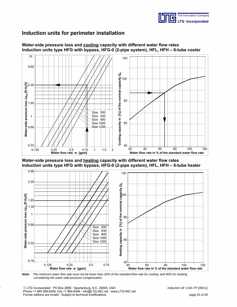
Induction units for perimeter installation
Water-side pressure loss and cooling capacity with different water flow ratesInduction units type HFG with bypass, HFG-0 (2-pipe system), HFL, HFH – 6-tube cooler
0.125 0.25 0.5 0.75 1 1.5
0.33
0.66
1
1.65
3.30
6.60
10
20 40 60 80 100 12040
60
80
100
120
Water flow rate in % of the standard water flow rateWater flow rate w [gpm]
Water-sidepressureloss
∆pw[ftH2O]
Coolingcapacityin[%]ofthenominalcapacityQc
2
Size 500Size 630Size 800Size 1000Size 1250
Water-side pressure loss and heating capacity with different water flow ratesInduction units type HFG with bypass, HFG-0 (2-pipe system), HFL, HFH – 6-tube heater
0.125 0.25 0.5 0.750.16
0.33
0.66
1.65
3.30
4.95
40 60 80 100 12040
60
80
100
120
Size 500Size 630Size 800Size 1000Size 1250
Water-sidepressureloss
∆pw[ftH2O]
Heatingcapacityin[%]ofthenominalcapacityQh
Water flow rate in % of the standard water flow rateWater flow rate w [gpm]
1.32
1
Note: The minimum water flow rate must not be lower than 20% of the standard flow rate for cooling, and 40% for heating,considering the water-side pressure compensation.
The Innovation Company
LTG Incorporated
E LTG Incorporated · PO Box 2889 · Spartanburg, S.C. 29304, USA Induction sill -USA-TP (08/11)Phone +1 864 599-6340, Fax +1 864-6344 · [email protected] · www.LTG-INC.netFormer editions are invalid · Subject to technical modifications page 24 of 29
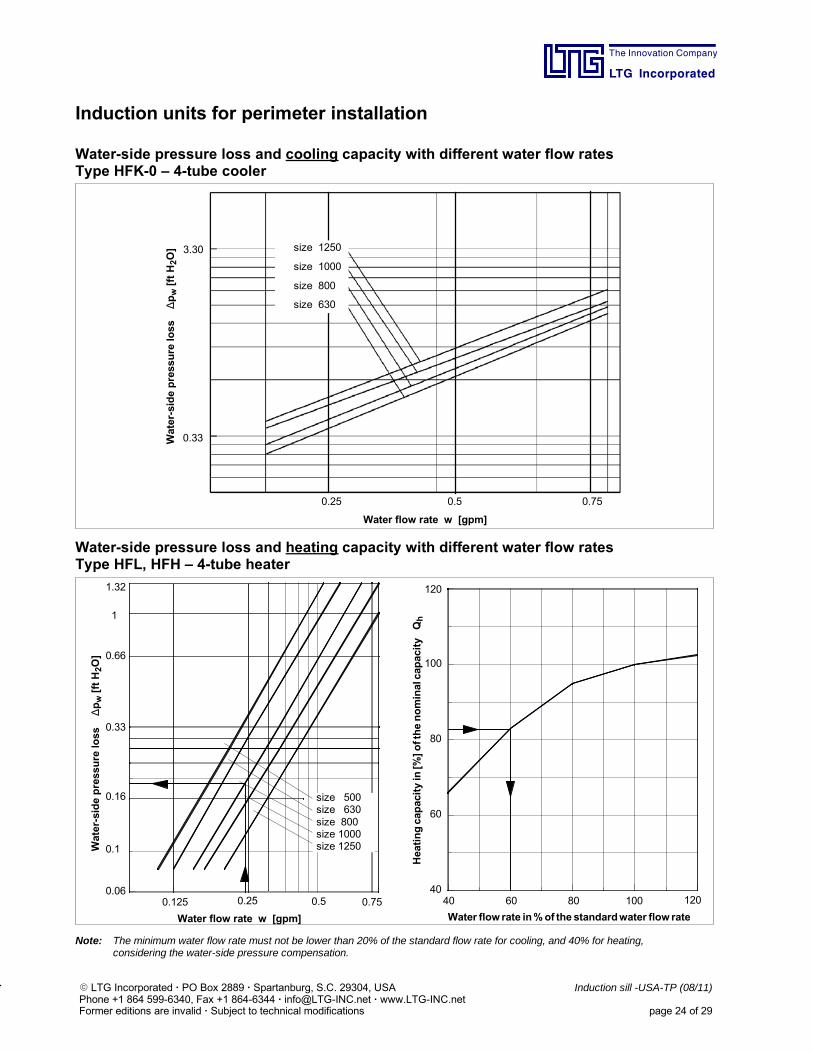
Induction units for perimeter installation
Water-side pressure loss and cooling capacity with different water flow ratesType HFK-0 – 4-tube cooler
Water-sidepressureloss
∆pw[ftH2O]
Water flow rate w [gpm]
0.25 0.5 0.75
3.30
0.33
size 1250
size 1000
size 800
size 630
Water-side pressure loss and heating capacity with different water flow ratesType HFL, HFH – 4-tube heater
0.125 0.25 0.5 0.750.06
0.1
0.16
0.33
0.66
1
1.32
40 60 80 100 12040
60
80
100
120
Water flow rate w [gpm] Water flow rate in%of the standardwater flow rate
Heatingcapacityin[%]ofthenominalcapacityQh
Water-sidepressureloss
∆pw[ftH2O]
size 500size 630size 800size 1000size 1250
Note: The minimum water flow rate must not be lower than 20% of the standard flow rate for cooling, and 40% for heating,considering the water-side pressure compensation.
The Innovation Company
LTG Incorporated
E LTG Incorporated · PO Box 2889 · Spartanburg, S.C. 29304, USA Induction sill -USA-TP (08/11)Phone +1 864 599-6340, Fax +1 864-6344 · [email protected] · www.LTG-INC.netFormer editions are invalid · Subject to technical modifications page 25 of 29
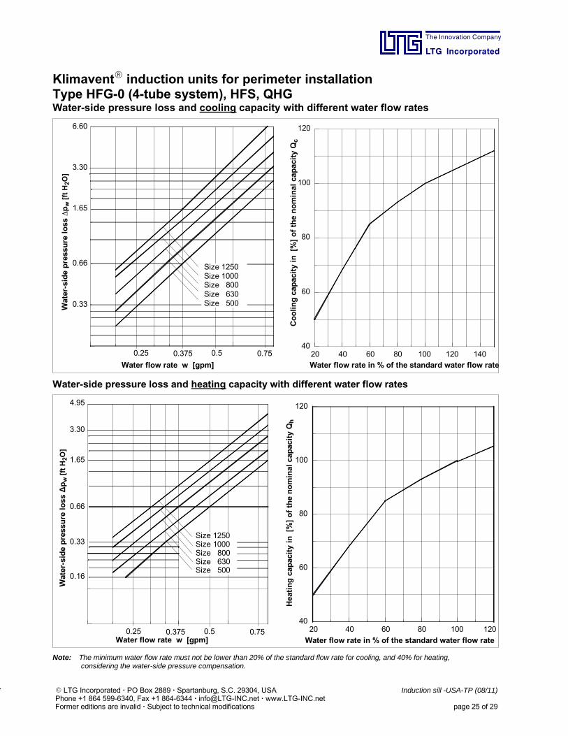
KlimaventR induction units for perimeter installationType HFG-0 (4-tube system), HFS, QHGWater-side pressure loss and cooling capacity with different water flow rates
0.25 0.375 0.5 0.75
0.33
0.66
1.65
3.30
6.60
20 40 60 80 100 120 14040
60
80
100
120
Water flow rate in % of the standard water flow rateWater flow rate w [gpm]
Water-sidepressureloss
pw[ftH2O]
Coolingcapacityin[%]ofthenominalcapacityQc
Size 1250Size 1000Size 800Size 630Size 500
Water-side pressure loss and heating capacity with different water flow rates
0.16
0.33
0.66
1.65
3.30
20 40 60 80 100 12040
60
80
100
1204.95
Water flow rate w [gpm] Water flow rate in % of the standard water flow rate
Size 1250Size 1000Size 800Size 630Size 500
Water-sidepressureloss
∆pw[ftH2O]
Heatingcapacityin[%]ofthenominalcapacityQh
0.25 0.375 0.5 0.75
Note: The minimum water flow rate must not be lower than 20% of the standard flow rate for cooling, and 40% for heating,considering the water-side pressure compensation.
The Innovation Company
LTG Incorporated
E LTG Incorporated · PO Box 2889 · Spartanburg, S.C. 29304, USA Induction sill -USA-TP (08/11)Phone +1 864 599-6340, Fax +1 864-6344 · [email protected] · www.LTG-INC.netFormer editions are invalid · Subject to technical modifications page 26 of 29
Induction units for perimeter installation
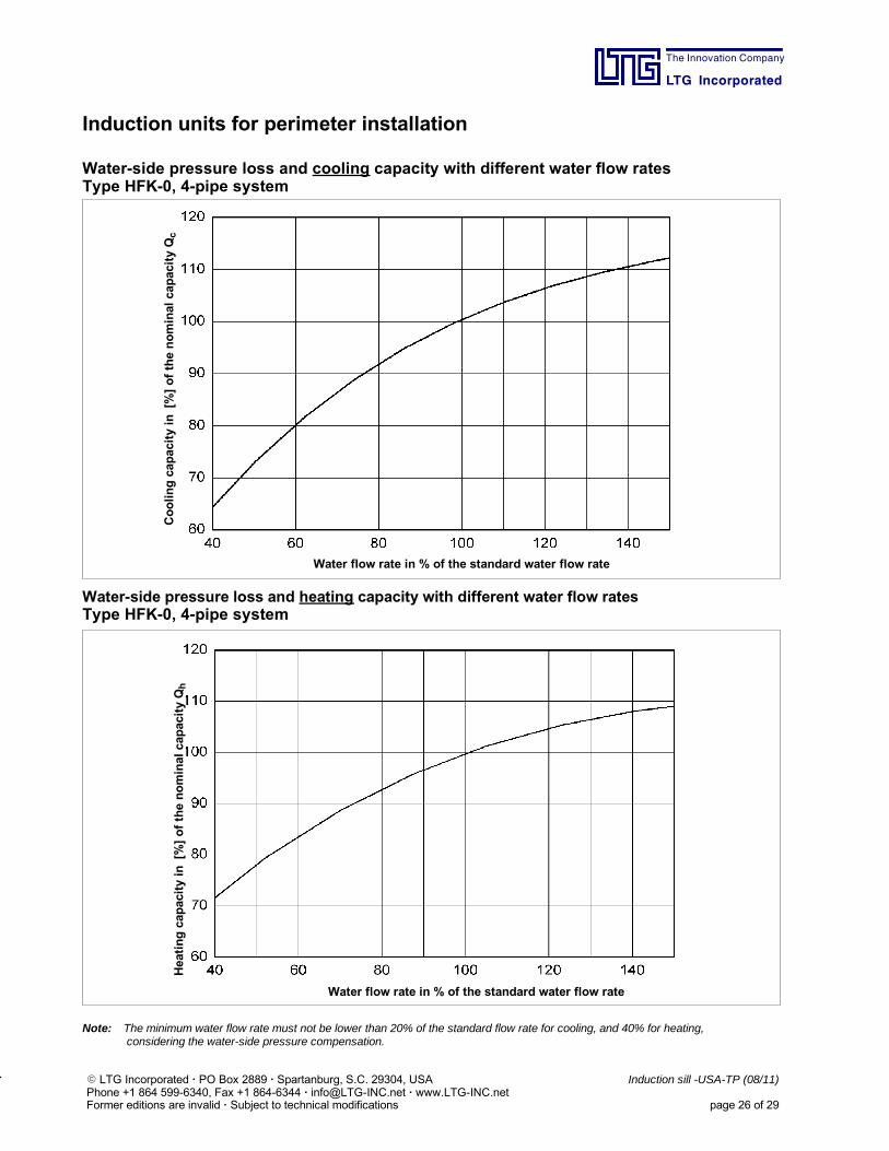
Water-side pressure loss and cooling capacity with different water flow ratesType HFK-0, 4-pipe system
Coolingcapacityin[%]ofthenominalcapacityQc
Water flow rate in % of the standard water flow rate
Water-side pressure loss and heating capacity with different water flow ratesType HFK-0, 4-pipe system
Heatingcapacityin[%]ofthenominalcapacityQh
Water flow rate in % of the standard water flow rate
Note: The minimum water flow rate must not be lower than 20% of the standard flow rate for cooling, and 40% for heating,considering the water-side pressure compensation.
The Innovation Company
LTG Incorporated
E LTG Incorporated · PO Box 2889 · Spartanburg, S.C. 29304, USA Induction sill -USA-TP (08/11)Phone +1 864 599-6340, Fax +1 864-6344 · [email protected] · www.LTG-INC.netFormer editions are invalid · Subject to technical modifications page 27 of 29
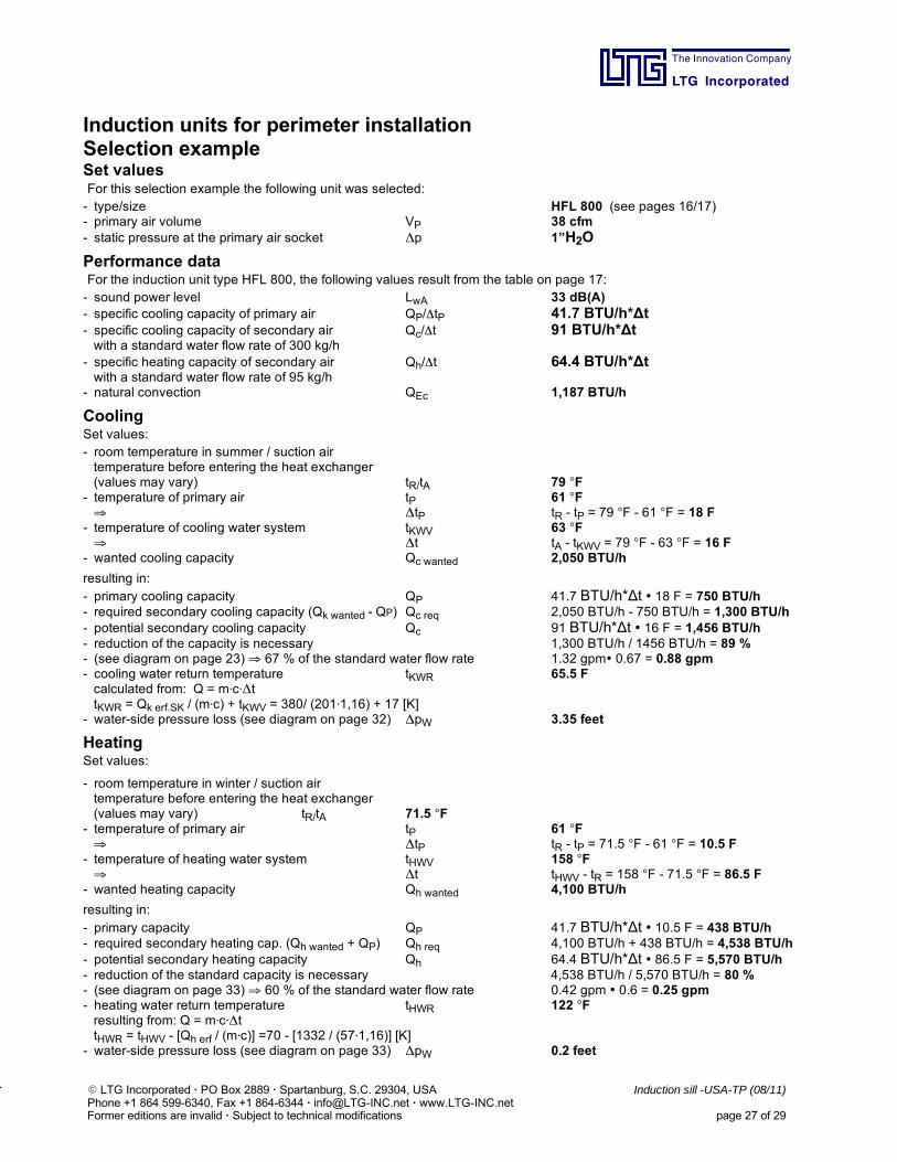
Induction units for perimeter installationSelection exampleSet valuesFor this selection example the following unit was selected:- type/size HFL 800 (see pages 16/17)- primary air volume VP 38 cfm- static pressure at the primary air socket Δp 1”H2O
Performance dataFor the induction unit type HFL 800, the following values result from the table on page 17:- sound power level LwA 33 dB(A)- specific cooling capacity of primary air QP/tP 41.7 BTU/h*∆t- specific cooling capacity of secondary air Qc/t 91 BTU/h*∆twith a standard water flow rate of 300 kg/h
- specific heating capacity of secondary air Qh/t 64.4 BTU/h*∆twith a standard water flow rate of 95 kg/h
- natural convection QEc 1,187 BTU/h
CoolingSet values:- room temperature in summer / suction airtemperature before entering the heat exchanger(values may vary) tR/tA 79 F
- temperature of primary air tP 61 F ΔtP tR - tP = 79 F - 61 F = 18 F
- temperature of cooling water system tKWV 63 F Δt tA - tKWV = 79 F - 63 F = 16 F
- wanted cooling capacity Qc wanted 2,050 BTU/h
resulting in:- primary cooling capacity QP 41.7 BTU/h*∆t 18 F = 750 BTU/h- required secondary cooling capacity (Qk wanted - QP) Qc req 2,050 BTU/h - 750 BTU/h = 1,300 BTU/h- potential secondary cooling capacity Qc 91 BTU/h*∆t 16 F = 1,456 BTU/h- reduction of the capacity is necessary 1,300 BTU/h / 1456 BTU/h = 89 %- (see diagram on page 23) 67 % of the standard water flow rate 1.32 gpm 0.67 = 0.88 gpm- cooling water return temperature tKWR 65.5 Fcalculated from: Q = mcΔttKWR = Qk erf.SK / (mc) + tKWV = 380/ (2011,16) + 17 [K]
- water-side pressure loss (see diagram on page 32) ΔpW 3.35 feet
HeatingSet values:
- room temperature in winter / suction airtemperature before entering the heat exchanger(values may vary) tR/tA 71.5 F
- temperature of primary air tP 61 F ΔtP tR - tP = 71.5 F - 61 F = 10.5 F
- temperature of heating water system tHWV 158 F Δt tHWV - tR = 158 F - 71.5 F = 86.5 F
- wanted heating capacity Qh wanted 4,100 BTU/h
resulting in:- primary capacity QP 41.7 BTU/h*∆t 10.5 F = 438 BTU/h- required secondary heating cap. (Qh wanted + QP) Qh req 4,100 BTU/h + 438 BTU/h = 4,538 BTU/h- potential secondary heating capacity Qh 64.4 BTU/h*∆t 86.5 F = 5,570 BTU/h- reduction of the standard capacity is necessary 4,538 BTU/h / 5,570 BTU/h = 80 %- (see diagram on page 33) 60 % of the standard water flow rate 0.42 gpm 0.6 = 0.25 gpm- heating water return temperature tHWR 122 Fresulting from: Q = mcΔttHWR = tHWV - [Qh erf / (mc)] =70 - [1332 / (571,16)] [K]
- water-side pressure loss (see diagram on page 33) ΔpW 0.2 feet
The Innovation Company
LTG Incorporated
E LTG Incorporated · PO Box 2889 · Spartanburg, S.C. 29304, USA Induction sill -USA-TP (08/11)Phone +1 864 599-6340, Fax +1 864-6344 · [email protected] · www.LTG-INC.netFormer editions are invalid · Subject to technical modifications page 28 of 29
Induction units for perimeter installation
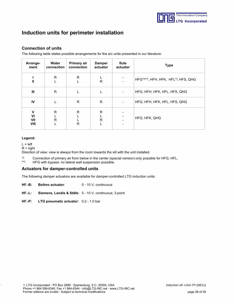
Connection of unitsThe following table states possible arrangements for the a/c units presented in our literature:
Arrange-ment
Waterconnection
Primary airconnection
Damperactuator
fluteactuator
Type
III
RL
RL
LR
--
HFG*)**), HFH, HFK, HFL*), HFS, QHG
III R L L - HFG, HFH, HFK, HFL, HFS, QHG
IV L R R - HFG, HFH, HFK, HFL, HFS, QHG
VVIVIIVIII
RLRL
RLLR
RLRL
----
HFG, HFK, QHG
Legend:
L = leftR = rightDirection of view: view is always from the room towards the sill with the unit installed.
*) Connection of primary air from below in the center (special version) only possible for HFG, HFL.**) HFG with bypass: no lateral wall suspension possible.
Actuators for damper-controlled units
The following damper actuators are available for damper-controlled LTG induction units:
HF.-B: Belimo actuator: 0 - 10 V, continuous
HF.-L: Siemens, Landis & Stäfa: 0 - 10 V, continuous; 3-point
HF.-P: LTG pneumatic actuator: 0.2 - 1.0 bar
The Innovation Company
LTG Incorporated
E LTG Incorporated · PO Box 2889 · Spartanburg, S.C. 29304, USA Induction sill -USA-TP (08/11)Phone +1 864 599-6340, Fax +1 864-6344 · [email protected] · www.LTG-INC.netFormer editions are invalid · Subject to technical modifications page 29 of 29
Induction units for perimeter installation
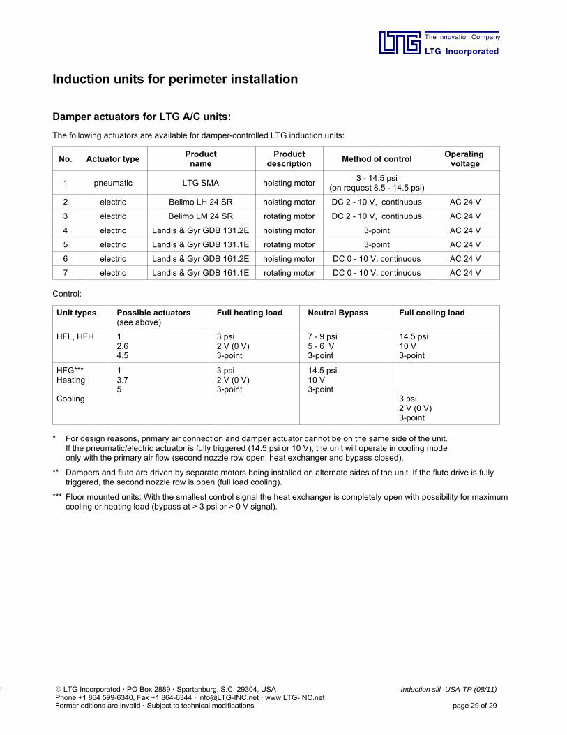
Damper actuators for LTG A/C units:
The following actuators are available for damper-controlled LTG induction units:
No. Actuator typeProductname
Productdescription
Method of controlOperatingvoltage
1 pneumatic LTG SMA hoisting motor3 - 14.5 psi
(on request 8.5 - 14.5 psi)
2 electric Belimo LH 24 SR hoisting motor DC 2 - 10 V, continuous AC 24 V
3 electric Belimo LM 24 SR rotating motor DC 2 - 10 V, continuous AC 24 V
4 electric Landis & Gyr GDB 131.2E hoisting motor 3-point AC 24 V
5 electric Landis & Gyr GDB 131.1E rotating motor 3-point AC 24 V
6 electric Landis & Gyr GDB 161.2E hoisting motor DC 0 - 10 V, continuous AC 24 V
7 electric Landis & Gyr GDB 161.1E rotating motor DC 0 - 10 V, continuous AC 24 V
Control:
Unit types Possible actuators(see above)
Full heating load Neutral Bypass Full cooling load
HFL, HFH 12.64.5
3 psi2 V (0 V)3-point
7 - 9 psi5 - 6 V3-point
14.5 psi10 V3-point
HFG***Heating
Cooling
13.75
3 psi2 V (0 V)3-point
14.5 psi10 V3-point
3 psi2 V (0 V)3-point
* For design reasons, primary air connection and damper actuator cannot be on the same side of the unit.If the pneumatic/electric actuator is fully triggered (14.5 psi or 10 V), the unit will operate in cooling modeonly with the primary air flow (second nozzle row open, heat exchanger and bypass closed).
** Dampers and flute are driven by separate motors being installed on alternate sides of the unit. If the flute drive is fullytriggered, the second nozzle row is open (full load cooling).
*** Floor mounted units: With the smallest control signal the heat exchanger is completely open with possibility for maximumcooling or heating load (bypass at > 3 psi or > 0 V signal).
1.Dient zur Identifizierung der letzten S
The Innovation Company
LTG Incorporated
Induction sill - USA - TP (08/11) 416-131E LTG Incorporated • Former editions are invalid • Subject to technical modifications
Product OverviewLTG Air-Water Systems
FanPower
Ceiling Installation Floor Installation
FVS Univent FVM FVD
FVPpulseSystem PulseVentilation
Ceiling Installation Floor Installation
LVC System Indivent VFC VKB
VKH QVC SKB
VKE
KFA cool wave
HFFsuiteSilentSuite
HFV/HFVsfSystem SmartFlow
HFB/HFBsfSystem SmartFlow
LHG System Indivent HFG
HDF/HDFsfSystem SmartFlow
QHG
HDC
Ceiling installation Floor Installation
Induction
Decentral
Sill Installation
Sill Installation
Sill Installation
LTG Engineering Services Comfort Air Technology
– Induction Units
– Decentralised Ventilation Units
– Fan Coil Units
Engineering Services