Embed Size (px)
Citation preview

Technical Brochure
Metalis Energy Ltd
Unit 1 Birchwood Way, Ashwood Business Park, Ashington, Northumberland, NE63 0XD. Registered in the UK: 06758233
metalisenergy.com

2
Metalis Energy are world leading specialists in
high integrity, high pressure, safety critical
pipeline components and drilling manifold
systems for today's latest generation high-
performance environment drill-rigs and drill
ship applications. In today’s demanding deep-
water harsh environments where safety, high-
performance and certified quality materials
are absolutely paramount, why take a chance
using substandard unquantified materials
where quality and testing are in doubt.
All our products are manufactured in the UK,
Europe or the USA and have a proven track
record in the harshest drilling environments.
All products are design verified and
independently certified by either ABS or DNV
as standard.
If you need high integrity, high pressure
pipeline components for a priority new-build or
tight deadline drill-rig refurbishment, whether
it’s a jack-up, semi-sub or drillship for choke &
kill, high pressure / high temperature mud &
cement line applications… Metalis Energy has
the solution for you.
metalisenergy.com

3
Contents
4. Products Overview
5. Quality Assurance
6. Seamless Pipe
8. Manifold Fittings
20. ANSI B16.9 Fittings
29. API Products
37. Hammer Lug Unions
41. API Valves
50. Pipeline Hubs and Clamps
57. API 16c Hubs and Clamps
4
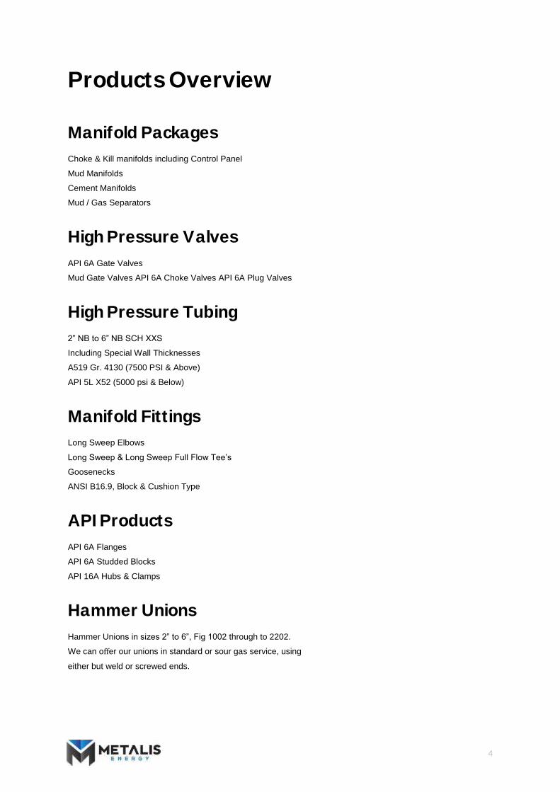
Products Overview
Manifold Packages
Choke & Kill manifolds including Control Panel
Mud Manifolds
Cement Manifolds
Mud / Gas Separators
High Pressure Valves
API 6A Gate Valves
Mud Gate Valves API 6A Choke Valves API 6A Plug Valves
High Pressure Tubing
2” NB to 6” NB SCH XXS
Including Special Wall Thicknesses
A519 Gr. 4130 (7500 PSI & Above)
API 5L X52 (5000 psi & Below)
Manifold Fittings
Long Sweep Elbows
Long Sweep & Long Sweep Full Flow Tee’s
Goosenecks
ANSI B16.9, Block & Cushion Type
API Products
API 6A Flanges
API 6A Studded Blocks
API 16A Hubs & Clamps
Hammer Unions
Hammer Unions in sizes 2” to 6”, Fig 1002 through to 2202.
We can offer our unions in standard or sour gas service, using
either but weld or screwed ends.

5
Quality Assurance
Our dedication to quality assurance is second
to none. All of our projects are conducted
from start to finish using our strict quality
system which is in full accordance with BS EN
ISO 9001. We also ensure that all of the
products we offer are in accordance with all
relative industry standards and specific
customer requirements. We are always open
to any input from our customers as to how to
improve our products and services as we
continue to grow. All of our products can also
be manufactured to meet any necessary
specifications brought forward by our clients
whether it is chemical compositions or
specialist packaging.
All our products are manufactured in the UK,
Europe or the USA and have a proven track
record in the harshest drilling environments.
All products are design verified and
independently certified by either ABS or DNV
as standard.
metalisenergy.com

6
Seamless Pipe
All pipe and tubing supplied by Metalis Energy is supplied in accordance with the following international
standards where applicable.
API spec 5L American petroleum institute specification for line pipe
NACE MR 01 75 Sulphide Stress Corrosion Cracking Resistant Metallic
Materials for Oil Field Equipment
ASME B16.10 Welded and Seamless Wrought Steel Pipes
ASTM American Society for Testing and Materials.
Material certification to BS EN 10204 3.1 is provided as standard, material certification to BS EN 10204 3.2
can be provided if required.
Table 4.1
Material Min Tensile Strength Min Yield Strength
Brinell Hardness number
Charpy Impact value
ASTM A106 Gr B 35,000psi 60,000psi - -
A333 Gr 6 35,000psi 60,000psi - 18J min AV at -45 deg C
API 5L X52 52,000psi 65,000psi - 27j min AV at -50 deg C
A182 F316L 25,000psi 70,000psi - -
A519 4130 85,000psi 105,000psi 237 HB 42K min AV -50 deg C
Metalis can provide pipe and tubing in other material grades, please contact us with any other material
requirements you may have. Specific working pressures available upon request.
See the tables below for the dimensional data of standard Metalis pipe sizes. Please note that these are lists of
only the most common sizes stocked by Metalis. If you have any requirements for specific sizes or special
materials that are not in the lists please contact [email protected] and we will be more than happy to
assist.

7
Table 4.2
Nominal Bore (in)
Outside Diameter (Inches)
Outside Diameter
(mm) Sch 80 Sch XS Sch 100 Sch 120 Sch 140 Sch 160 Sch XXS
1” 1.315 33.401 Wall thickness (mm) Weight (kg/m)
4.55 3.29
4.55 3.29
- -
- -
- -
6.35 4.30
9.70 7.88
2” 2.375 60.325 Wall thickness (mm) Weight (kg/m)
5.54 7.60
5.54 7.60
- -
- -
- -
8.74 11.29
11.07 13.65
3” 3.500 88.900 Wall thickness (mm) Weight (kg/m)
7.62 15.51
7.62 15.51
- -
- -
- -
11.13 21.67
15.24 28.11
4” 4.500 114.300 Wall thickness (mm) Weight (kg/m)
8.56 22.64
8.56 22.64
- -
11.13 28.75
- -
13.49 34.05
17.12 41.66
5” 5.563 141.300 Wall thickness (mm) Weight (kg/m)
9.53 31.44
9.53 31.44
- -
12.70 40.90
- -
15.88 49.94
19.05 58.32
6” 6.625 168.275 Wall thickness (mm) Weight (kg/m)
10.97 43.21
10.97 43.21
- -
14.27 55.03
- -
18.26 68.53
21.92 80.43
Table 4.3 ‐ Common Specialist Pipe Sizes
Nominal Bore (in)
Outside Diameter (Inches)
Outside Diameter
(mm) Inside Diameter
(inches) Inside Diameter
(mm) Wall thickness
(mm) Weight (kg/m)
4” 4.5 114.3 3.0 76.2 19.05 44.39 5” 5.5 139.7 3.0 76.2 31.75 84.52 5” 5.75 146.05 4.0 101.6 22.23 66.07 6” 6.75 171.45 5.0 127.0 22.23 84.53 - 7.4 187.96 4.0 101.6 43.18 154.17

8
High Pressure Manifold Fittings
Metalis Energy only supplies the highest quality manifold fittings manufactured in the UK from wrought steel forgings
– far superior to steel casings or steel plate. The fittings have been designed to meet all of the following international
standards:
MSS‐SP75 Specifications for High test Wrought Butt Weld Fittings.
ANSI B31.3 Chemical Plant and Petroleum Refinery Piping.
ANSI 16.9 Factory made Wrought Steel Butt Weld Fittings.
NACE MR‐01‐75 Sulphide Stress Cracking Resistant Metallic Materials for Oil Field Equipment. ASME VIII
Division 1 section 13.10 Boiler and Pressure Vessel Code.
API 6A Specifications for Wellhead and Christmas Tree Equipment

9
Metalis forged manifold fixings are available for the following pressure ratings:
MAX WORKING
PREESSURE* 5,000psi 10,000psi 15,000psi
Test pressure 10,000psi 15,000psi 22,500psi
Material Carbon Manganese Steel
(ASTM A860 Gr WPHY
52)
Low Alloy steel
(AISI 4130)
Low Alloy steel
(AISI 4130)
Min Yield 52,000psi 85,000psi 85,000psi
Operating temps -46 to 204 deg C -46 to 204 deg C -46 to 204 deg C
*Working pressures can be affected by a number of factors such as butt weld prep sizes. Please contact Metalis for
specific working pressures.
All tees and crosses can be supplied with reducing connections, these may effect the sizes of these fittings, please
contact Metalis for clarification.
See the tables below for the dimensional data of standard Metalis manifold fittings. Please note that these are lists of
only the most common sizes stocked by Metalis. If you have any requirements for specific sizes or special materials
that are not in the lists please contact [email protected] and we will be more than happy to assist.

10
Long sweep 90 degree elbow
Table 5.1 – Long Sweep 90 deg Elbow Standard Sizes (All dims in inches unless otherwise stated)
NB A B C D E WEIGHT
(KG)
2” XXS 8.00 8.00 1.50 2.375 3.50 14
3” XXS 8.00 8.00 2.30 3.50 4.50 22
4” XXS 11.00 11.00 3.15 4.50 5.50 42
5” XXS 12.00 12.00 4.06 5.56 6.63 57
6” XXS 15.00 15.00 4.90 6.625 8.00 94
5.5” OD x 3.0” ID 12.00 12.00 3.06 5.50 6.63 62
6.75” OD x 5.0” ID 15.00 15.00 5.00 6.75 8.00 94

11
Long sweep 45 degree elbow
Table 5.2 – Long Sweep 45 deg Elbow Standard Sizes (All dims in inches unless otherwise stated)
NB A B C D E WEIGHT
(KG)
2” XXS 8.00 6.00 1.50 2.375 3.50 9
3” XXS 8.00 6.00 2.30 3.50 4.50 15
4” XXS 11.00 8.25 3.15 4.50 5.50 29
5” XXS 11.50 9.50 4.06 5.56 6.63 38
6” XXS 13.69 12.00 4.90 6.625 8.00 72
5.5” OD x 3.0” ID 11.50 9.50 3.06 5.50 6.63 43
6.75” OD x 5.0” ID 13.69 12.00 5.00 6.75 8.00 72

12
Long sweep full flow tee
Table 5.3 – Long Sweep Full Flow Tee Standard Sizes (All dims in inches unless otherwise stated)
NB A B C D E F WEIGHT
(KG)
2” XXS 16.00 8.00 8.00 1.50 2.37 4.50 44
3” XXS 16.00 8.00 8.00 2.30 3.50 4.50 38
4” XXS 22.00 11.00 11.00 3.15 4.50 5.56 63
5” XXS 24.00 12.00 12.00 4.06 5.56 6.63 88
6” XXS 30.00 15.00 15.00 4.90 6.63 7.75 170
5.5” OD x 3.0” ID 24.00 12.00 12.00 3.06 5.50 6.63 93
6.75 OD x 5.00” ID 30.00 15.00 15.00 5.00 6.75 7.75 170

13
Long sweep tee
Table 5.4 – Long Sweep Tee Standard Sizes (All dims in inches unless otherwise stated)
NB A B C D E F WEIGHT
(KG)
2” XXS 13.00 8.00 8.00 1.50 2.37 4.50 36
3” XXS 13.00 8.00 8.00 2.30 3.50 4.50 31
4” XXS 16.00 11.00 11.00 3.15 4.50 5.56 52
5” XXS 19.00 12.00 12.00 4.06 5.56 6.63 75
6” XXS 27.00 15.00 15.00 4.90 6.63 7.75 145
5.5” OD x 3.0” ID 19.00 12.00 12.00 3.06 5.50 6.63 80
6.75 OD x 5.00” ID 27.00 15.00 15.00 5.00 6.75 7.75 145

14
Long Sweep Tee C/W Integral Bull Plug
Table 5.5 – Long Sweep Tee C/W Bull Plug Standard Sizes (All dims in inches unless otherwise stated)
NB A B C D E F WEIGHT
(KG)
2” XXS 15.20 8.00 8.00 1.50 2.37 4.50 40
3” XXS 15.20 8.00 8.00 2.30 3.50 4.50 34
4” XXS 19.50 11.00 11.00 3.15 4.50 5.56 59
5” XXS 23.00 12.00 12.00 4.06 5.56 6.63 86
6” XXS 31.70 15.00 15.00 4.90 6.63 7.75 160
5.5” OD x 3.0” ID 23.00 12.00 12.00 3.06 5.50 6.63 91
6.75 OD x 5.00” ID 31.70 15.00 15.00 5.00 6.75 7.75 16

15
Long Sweep Full Flow Cross
Table 5.6 – Long Sweep Full Flow Cross Standard Sizes (All dims in inches unless otherwise stated)
NB A B C D E F WEIGHT
(KG)
2” XXS 16.00 8.00 8.00 1.50 2.37 4.50 59
3” XXS 16.00 8.00 8.00 2.30 3.50 4.50 60
4” XXS 22.00 11.00 11.00 3.15 4.50 5.56 81.
5” XXS 24.00 12.00 12.00 4.06 5.56 6.63 111
6” XXS 30.00 15.00 15.00 4.90 6.63 7.75 243
5.5” OD x 3.0” ID 24.00 12.00 12.00 3.06 5.50 6.63 116
6.75 OD x 5.00” ID 30.00 15.00 15.00 5.00 6.75 7.75 243

16
90 Degree 3d Double Backed Elbow
Table 5.7 – 90 Deg 3D Double Backed Elbow Standard Sizes (All dims in inches unless otherwise stated)
NB A B C D E WEIGHT (KG)
2” XXS 7.00 7.00 1.50 2.37 3.50 11
3” XXS 12.00 12.00 2.30 3.50 4.50 30
4” XXS 14.00 14.00 3.15 4.50 5.50 47
5” XXS 17.00 17.00 4.06 5.56 6.60 75
6” XXS 21.00 21.00 4.90 6.63 8.25 135
5.5” OD x 3.0” ID 17.00 17.00 3.06 5.50 6.60 80
6.75 OD x 5.00” ID 21.00 21.00 5.00 6.75 8.25 135

17
45 Degree 3d Doubled Backed Elbow
Table 5.8 – 45 Deg 3D Double Backed Elbow Standard Sizes (All dims in inches unless otherwise stated)
NB A B C D E WEIGHT (KG)
2” XXS 4.76 4.76 1.50 2.37 3.50 10
3” XXS 6.73 6.73 2.30 3.50 4.33 20
4” XXS 6.97 6.97 3.15 4.50 5.50 28
5” XXS 8.22 8.22 4.06 5.56 6.60 45
6” XXS 10.43 10.43 4.90 6.63 8.25 94
5.5” OD x 3.0” ID 8.22 8.22 3.06 5.50 6.60 50
6.75 OD x 5.00” ID 10.43 10.43 5.00 6.75 8.25 94

18
Standpipe Gooseneck 160 Degree C/W Top Outlet
Table 5.9 – Standpipe Gooseneck 160 Deg Standard Sizes (All dims in inches unless otherwise stated)
NB A B C D E WEIGHT (KG)
2” XXS 13.00 12.00 1.50 2.37 4.50 40
3” XXS 13.00 12.00 2.30 3.50 4.50 42
4” XXS 16.00 14.00 3.15 4.50 5.56 75
5” XXS 19.00 16.00 4.06 5.56 6.63 107
6” XXS 27.00 24.00 4.90 6.63 7.75 210
5.5” OD x 3.0” ID 19.00 16.00 3.06 5.50 6.63 112
6.75 OD x 5.00” ID 27.00 24.00 5.00 6.75 7.75 210

19
Standpipe Gooseneck 160 Degree C/W Top Integral Bullplug
Table 5.10 – Standpipe Gooseneck 160 Deg C/W Top Bull Plug Standard Sizes (All dims in inches unless
otherwise stated)
NB A B C D E WEIGHT (KG)
2” XXS 15.20 12.00 1.50 2.37 4.50 45
3” XXS 15.20 12.00 2.30 3.50 4.50 47
4” XXS 19.50 14.00 3.15 4.50 5.56 81
5” XXS 23.00 16.00 4.06 5.56 6.63 117
6” XXS 29.00 24.00 4.90 6.63 7.75 225
5.5” OD x 3.0” ID 23.00 16.00 3.06 5.50 6.63 122
6.75 OD x 5.00” ID 29.00 24.00 5.00 6.75 7.75 225

20
ANSI B16.9 Fittings
Metalis Energy only supplies the highest quality ANSI B16.9 fixings & block type fittings manufactured in UK. The fittings have been designed to meet all of the following international standards:
MSS‐SP75 Specifications for High test Wrought Butt Weld Fittings
MSS‐SP43 Wrought stainless steel butt weld fittings
ANSI B31.3 Chemical Plant and Petroleum Refinery Piping
ANSI 16.9 Factory made Wrought Steel Butt Weld Fittings
NACE MR‐01‐75 Sulphide Stress Cracking Resistant Metallic Materials for Oil Field
Equipment
ASME VIII Division 1 section 13.10 Boiler and Pressure Vessel Code.
API 6A Specifications for Wellhead and Christmas Tree Equipment.

21
Table 6.1 – Standard Fitting Materials
Material Min Tensile Strength Min Yield Strength Brinell Hardness
number Charpy Impact value
A182 Gr 316L 25,000psi 70,000psi - - A234 Gr WPB 35,000psi 60,000psi 197 HB - A420 WPL6 35,000psi 60,000psi - 18J min AV -45 deg C
A860 Gr WPHY52 52,000psi 66,000psi 235 HB 27J min AV -50 deg C A182 F51 UNS 31803 65,000psi 90,000psi 237 HB 27J min AV -50 deg C
AISI 4130 75,000psi 105,000psi 237 HB 42J min AV -50 deg C * Metalis can provide fittings in other material grades, please contact us with any other material requirements you may have. Specific working pressures available upon request. See the tables below for the dimensional data of standard Metalis fitting sizes. Please note that these are lists of only the most common sizes stocked by Metalis. If you have any requirements for specific sizes or special materials that are not in the lists please contact [email protected] and we will be more than happy to assist.

22
90 Degree Long Radius Elbow
Table 6.2 – 90 Deg Long Radius Elbow Standard Sizes (All dims in inches unless otherwise stated)
NB A B C WEIGHT (KG)
2” XXS 3.00 1.50 2.37 2
3” XXS 4.50 2.30 3.50 5
4” XXS 6.00 3.15 4.50 10
5” XXS 7.50 4.06 5.56 18
6” XXS 9.00 4.90 6.63 30
5.5” OD x 3” ID 7.50 3.00 5.50 22
6.75” OD x 5” ID 9.00 5.00 6.75 31

23
45 Degree Long Radius Elbow
Table 6.3 – 45 Deg Long Radius Elbow Standard Sizes (All dims in inches unless otherwise stated)
NB A B C WEIGHT (KG)
2” XXS 1.38 1.50 2.37 1
3” XXS 2.00 2.30 3.50 3
4” XXS 2.50 3.15 4.50 5
5” XXS 3.10 4.06 5.56 9
6” XXS 3.75 4.90 6.63 15
5.5” OD x 3” ID 3.10 3.00 5.50 12
6.75” OD x 5” ID 3.75 5.00 6.75 16

24
Buttweld Equal Tee
Table 6.4 – Equal Tee Standard Sizes (All dims in inches unless otherwise stated)
NB A B C D E WEIGHT (KG)
2” XXS 5.04 2.52 2.52 1.50 2.37 3
3” XXS 6.78 3.39 3.39 2.30 3.50 8
4” XXS 8.24 4.12 4.12 3.15 4.50 17
5” XXS 9.76 4.88 4.88 4.06 5.56 25
6” XXS 11.26 5.63 5.63 4.90 6.63 39
5.5” OD x 3” ID 9.76 4.88 4.88 3.00 5.50 29
6.75” OD x 5” ID 11.26 5.63 5.63 5.00 6.75 40

25
Buttweld Equal Cross
Table 6.5 – Equal Cross Standard Sizes (All dims in inches unless otherwise stated)
NB A B C D E WEIGHT (KG)
2” XXS 5.04 2.52 2.52 1.50 2.37 4
3” XXS 6.78 3.39 3.39 2.30 3.50 9
4” XXS 8.24 4.12 4.12 3.15 4.50 18
5” XXS 9.76 4.88 4.88 4.06 5.56 26
6” XXS 11.26 5.63 5.63 4.90 6.63 40
5.5” OD x 3” ID 9.76 4.88 4.88 3.00 5.50 30
6.75” OD x 5” ID 11.26 5.63 5.63 4.90 6.63 42
* Reducing tees and crosses are available; these may alter the dimensions of the fittings. Please contact
Metalis for further information.
26
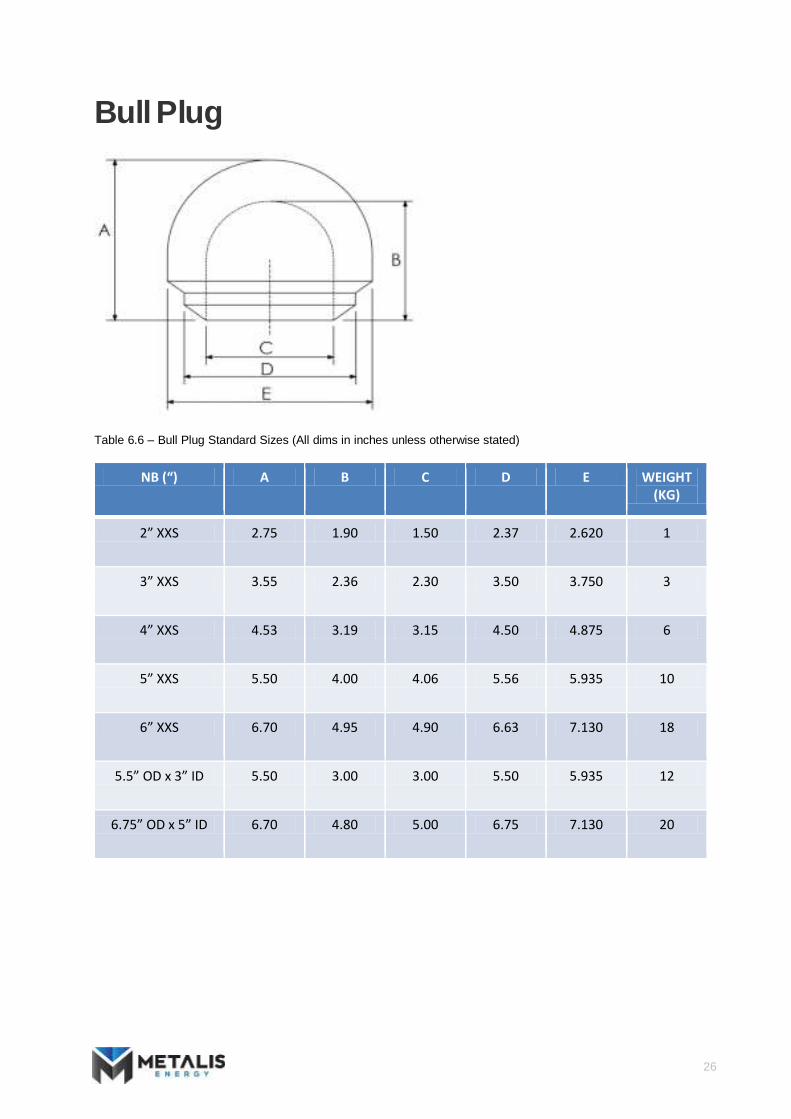
Bull Plug
Table 6.6 – Bull Plug Standard Sizes (All dims in inches unless otherwise stated)
NB (“) A B C D E WEIGHT (KG)
2” XXS 2.75 1.90 1.50 2.37 2.620 1
3” XXS 3.55 2.36 2.30 3.50 3.750 3
4” XXS 4.53 3.19 3.15 4.50 4.875 6
5” XXS 5.50 4.00 4.06 5.56 5.935 10
6” XXS 6.70 4.95 4.90 6.63 7.130 18
5.5” OD x 3” ID 5.50 3.00 3.00 5.50 5.935 12
6.75” OD x 5” ID 6.70 4.80 5.00 6.75 7.130 20

27
Concentric Reducer
Table 6.7 – Concentric Reducer Standard Sizes (All dims in inches unless otherwise stated)
NB (“) (SCH XXS)
A B C D E WEIGHT (KG)
3” x 2” 3.50 3.50 2.30 2.37 1.50 2.5
4” x 2” 4.00 4.50 3.15 2.37 1.50 4.5
4” x 3” 4.00 4.50 3.15 3.50 2.30 4.5
5” x 2” 5.00 5.56 4.06 2.37 1.50 7.5
5” x 3” 5.00 5.56 4.06 3.50 2.30 7.5
5” x 4” 5.00 5.56 4.06 4.50 3.15 7.5
6” x 3” 5.50 6.63 4.90 3.50 2.30 11
6” x 4” 5.50 6.63 4.90 4.50 3.15 11
6” x 5” 5.50 6.63 4.90 5.56 4.06 11

28
Eccentric Reducer
Table 6.8 – Eccentric Reducer Standard Sizes (All dims in inches unless otherwise stated)
NB (“) (SCH XXS)
A B C D E WEIGHT (KG)
3” x 2” 3.50 3.50 2.30 2.37 1.50 2.5
4” x 2” 4.00 4.50 3.15 2.37 1.50 4.5
4” x 3” 4.00 4.50 3.15 3.50 2.30 4.5
5” x 2” 5.00 5.56 4.06 2.37 1.50 7.5
5” x 3” 5.00 5.56 4.06 3.50 2.30 7.5
5” x 4” 5.00 5.56 4.06 4.50 3.15 7.5
6” x 3” 5.50 6.63 4.90 3.50 2.30 11
6” x 4” 5.50 6.63 4.90 4.50 3.15 11
6” x 5” 5.50 6.63 4.90 5.56 4.06 11

29
API 6A Products Metalis Energy only supplies the highest quality API 6A Products including flanges and studded blocks manufactured in UK. Flanges available are weld neck, target, blind & test blind. They have been designed to be strictly in accordance with the following standards: MSS‐SP75 Specifications for High test Wrought Butt Weld Fittings.
ANSI B31.3 Chemical Plant and Petroleum Refinery Piping. ANSI 16.9 Factory made Wrought Steel Butt Weld Fittings. NACE MR‐01‐75 Sulphide Stress Cracking Resistant Metallic Materials for Oil Field Equipment. API 6A Specifications for Wellhead and Christmas Tree Equipment. All API 6A equipment can be specified with the following:
PSL level 1, 2, 3 or 4 Material Class, AA, BB, CC, DD, EE‐NL
PR‐1 or PR‐2
Temperature classes: K thru Y (‐60degC to 345degC)
See the tables below for the dimensional data of standard Metalis flange sizes. Please note that these are lists of only the most common sizes stocked by Metalis. If you have any requirements for specific sizes or special materials that are not in the lists please contact [email protected] and we will be more than happy to assist. Metalis are capable of supplying all API sizes.

30
Type 6B Welding Neck Flanges 5,000 PSI Rated Working Pressure
Table 7.1 – API 6A – TYPE 6B 5,000psi Weldneck Flange dimensions (All dims in inches unless otherwise stated)
- A B - C D E F G H - - - - - J L M -
NO
MIN
AL
SIZE
& B
OR
E
OF
FLA
NG
ES
MA
X. B
OR
E
OU
TSID
E D
IAM
ETER
OF
FLA
NG
ES
TOLE
RA
NC
E
MA
X. C
HA
MFE
R
DIA
MET
ER O
F R
AIS
ED
FAC
E
TOTA
L TH
ICK
NES
S O
F
FLA
NG
E
BA
SIC
TH
ICK
NES
S O
F FL
AN
GE
DIA
MET
ER O
F H
UB
DIA
MET
ER O
F B
OLT
CIR
LCE
NU
MB
ER O
F B
OLT
S
DIA
MET
ER O
F B
OLT
S
DIA
MET
ER O
F B
OLT
H
OLE
S
BO
LT H
OLE
TO
LER
AN
CE
(SEE
NO
TES)
LEN
GTH
OF
BO
LTS
TOTA
L LE
NG
TH O
F
WEL
D N
ECK
LIN
E P
IPE
FLA
NG
E
NEC
K D
IAM
ETER
OF
WEL
D N
ECK
LIN
E P
IPE
FLA
NG
E
MA
XIM
UM
BO
RE
OF
WEL
D N
ECK
FLA
NG
E
RIN
G T
YP
E, R
X
2-1/16” 2.09 8.50 +0.06 0.12 4.88 1.81 1.50 4.12 6.50 8 7/8” 1.00 +0.06 6.00 4.31 2.38 1.72 24
2-9/16” 2.59 9.62 +0.06 0.12 5.38 1.94 1.62 4.88 7.50 8 1” 1.12 +0.06 6.50 4.44 2.88 2.16 27
3-1/8” 3.22 10.50 +0.06 0.12 6.62 2.19 1.88 5.25 8.00 8 1-1/8” 1.25 +0.06 7.25 4.94 3.50 2.65 35
4-1/16” 4.28 12.25 +0.06 0.12 7.62 2.44 2.12 6.38 9.50 8 1-1/4” 1.38 +0.06 8.00 5.19 4.50 3.47 39
5-1/8” 5.16 14.75 +0.06 0.12 9.00 3.19 2.88 7.75 11.50 8 1-1/2” 1.62 +0.06 10.00 6.44 5.56 4.34 44

31
Type 6BX Welding Neck Flanges 10,000 PSI Rated Working Pressure
Table 7.2 – API 6A – TYPE 6BX 10,000psi Weldneck Flange dimensions (All dims in inches unless otherwise stated)
- A B - C D E F G H R J - - - - - -
NO
MIN
AL
SIZE
&
BO
RE
OF
FLA
NG
ES
MA
X. B
OR
E
OU
TSID
E D
IAM
ETER
OF
FLA
NG
ES
TOLE
RA
NC
E
MA
X. C
HA
MFE
R
DIA
MET
ER O
F R
AIS
ED
FAC
E
TOTA
L TH
ICK
NES
S O
F
FLA
NG
E
LAR
GE
DIA
MET
ER O
F
HU
B
SMA
LL D
IAM
ETER
OF
HU
B
LEN
GTH
OF
HU
B
RA
DIU
S O
F H
UB
DIA
MET
ER O
F B
OLT
CIR
LCE
NU
MB
ER O
F B
OLT
S
DIA
MET
ER O
F B
OLT
S
DIA
MET
ER O
G B
OLT
HO
LES
BO
LT H
OLE
TOLE
RA
NC
E (S
EE
NO
TES)
MIN
IMU
M L
ENG
TH
OF
STU
D B
OLT
RIN
G N
UM
BER
1-13/16” 1.84 7.38 +0.06 0.12 4.12 1.66 3.50 2.56 1.91 0.38 5.75 8 ¾” 0.88 +0.06 5.00 151
2-1/16” 2.09 7.88 +0.06 0.12 4.38 1.73 3.94 2.94 2.03 0.38 6.25 8 ¾” 0.88 +0.06 5.25 152
2-9/16” 2.59 9.12 +0.06 0.12 5.19 2.02 4.75 3.62 2.25 0.38 7.25 8 7/8” 1.00 +0.06 6.00 153
3-1/16” 3.09 10.62 +0.06 0.12 6.00 2.30 5.59 4.34 2.50 0.38 8.50 8 1” 1.12 +0.06 6.75 154
4-1/16” 4.09 12.44 +0.06 0.12 7.28 2.77 7.19 5.75 2.88 0.38 10.19 8 1-1/8” 1.25 +0.06 8.00 155
5-1/8” 5.16 14.06 +0.06 0.12 8.69 3.13 8.81 7.19 3.19 0.38 11.81 12 1-1/8” 1.25 +0.06 8.75 169

32
Type 6BX Welding Neck Flanges 15,000 PSI Rated Working Pressure
Table 7.3 – API 6A – TYPE 6BX 15,000psi Weldneck Flange dimensions (All dims in inches unless otherwise stated)
- A B - C D E F G H R J - - - - - -
NO
MIN
AL
SIZE
&
BO
RE
OF
FLA
NG
ES
MA
X. B
OR
E
OU
TSID
E D
IAM
ETER
OF
FLA
NG
ES
TOLE
RA
NC
E
MA
X. C
HA
MFE
R
DIA
MET
ER O
F R
AIS
ED
FAC
E
TOTA
L TH
ICK
NES
S O
F
FLA
NG
E
LAR
GE
DIA
MET
ER O
F
HU
B
SMA
LL D
IAM
ETER
OF
HU
B
LEN
GTH
OF
HU
B
RA
DIU
S O
F H
UB
DIA
MET
ER O
F B
OLT
CIR
LCE
NU
MB
ER O
F B
OLT
S
DIA
MET
ER O
F B
OLT
S
DIA
MET
ER O
G B
OLT
HO
LES
BO
LT H
OLE
TOLE
RA
NC
E (S
EE
NO
TES)
MIN
IMU
M L
ENG
TH
OF
STU
D B
OLT
RIN
G N
UM
BER
1-13/16” 1.84 8.19 +0.06 0.12 4.19 1.78 3.84 2.81 1.88 0.38 6.31 8 7/8” 1.00 +.06 5.50 151
2-1/16” 2.09 8.75 +0.06 0.12 4.50 2.00 4.38 3.25 2.12 0.38 6.88 8 7/8” 1.00 +.06 6.00 152
2-9/16” 2.59 10.00 +0.06 0.12 5.25 2.25 5.06 3.94 2.25 0.38 7.88 8 1” 1.12 +.06 6.75 153
3-1/16” 3.09 11.31 +0.06 0.12 6.06 2.53 6.06 4.81 2.50 0.38 9.06 8 1-1/8” 1.25 +.06 7.50 154
4-1/16” 4.09 14.19 +0.06 0.12 7.62 3.09 7.69 6.25 2.88 0.62 11.44 8 1-3/8” 1.50 +.06 9.25 155
5-1/8” 5.16 16.50 +0.06 0.12 8.88 3.88 9.62 7.88 3.22 0.62 13.50 12 1-1/2” 1.62 +.09 11.50 169

33
Type 6BX Blind Flanges 10,000 PSI Rated Working Pressure
Table 7.4 – API 6A – TYPE 6BX 10,000psi Blind Flange dimensions (All dims in inches unless otherwise stated)
- A B - C D E F G H R J - - - - - -
NO
MIN
AL
SIZE
&
BO
RE
OF
FLA
NG
ES
MA
X. B
OR
E
OU
TSID
E D
IAM
ETER
OF
FLA
NG
ES
TOLE
RA
NC
E
MA
X. C
HA
MFE
R
DIA
MET
ER O
F R
AIS
ED
FAC
E
TOTA
L TH
ICK
NES
S O
F
FLA
NG
E
LAR
GE
DIA
MET
ER O
F
HU
B
SMA
LL D
IAM
ETER
OF
HU
B
LEN
GTH
OF
HU
B
RA
DIU
S O
F H
UB
DIA
MET
ER O
F B
OLT
CIR
LCE
NU
MB
ER O
F B
OLT
S
DIA
MET
ER O
F B
OLT
S
DIA
MET
ER O
G B
OLT
HO
LES
BO
LT H
OLE
TOLE
RA
NC
E (S
EE
NO
TES)
MIN
IMU
M L
ENG
TH
OF
STU
D B
OLT
RIN
G N
UM
BER
1-13/16” 1.84 7.38 +0.06 0.12 4.12 1.66 3.50 2.56 1.91 0.38 5.75 8 ¾” 0.88 +.06 5.00 151
2-1/16” 2.09 7.88 +0.06 0.12 4.38 1.73 3.94 2.94 2.03 0.38 6.25 8 ¾” 0.88 +.06 5.25 152
2-9/16” 2.59 9.12 +0.06 0.12 5.19 2.02 4.75 3.62 2.25 0.38 7.25 8 7/8” 1.00 +.06 6.00 153
3-1/16” 3.09 10.62 +0.06 0.12 6.00 2.30 5.59 4.34 2.50 0.38 8.50 8 1” 1.12 +.06 6.75 154
4-1/16” 4.09 12.44 +0.06 0.12 7.28 2.77 7.19 5.75 2.88 0.38 10.19 8 1-1/8” 1.25 +.06 8.00 155

34
Type 6BX Blind Flanges 15,000 PSI Rated Working Pressure
Table 7.5 – API 6A – TYPE 6BX 10,000psi Blind Flange dimensions (All dims in inches unless otherwise stated)
- A B - C D E F G H R J - - - - - -
NO
MIN
AL
SIZE
&
BO
RE
OF
FLA
NG
ES
MA
X. B
OR
E
OU
TSID
E D
IAM
ETER
OF
FLA
NG
ES
TOLE
RA
NC
E
MA
X. C
HA
MFE
R
DIA
MET
ER O
F R
AIS
ED
FAC
E
TOTA
L TH
ICK
NES
S O
F
FLA
NG
E
LAR
GE
DIA
MET
ER O
F
HU
B
SMA
LL D
IAM
ETER
OF
HU
B
LEN
GTH
OF
HU
B
RA
DIU
S O
F H
UB
DIA
MET
ER O
F B
OLT
CIR
LCE
NU
MB
ER O
F B
OLT
S
DIA
MET
ER O
F B
OLT
S
DIA
MET
ER O
G B
OLT
HO
LES
BO
LT H
OLE
TOLE
RA
NC
E (S
EE
NO
TES)
MIN
IMU
M L
ENG
TH
OF
STU
D B
OLT
RIN
G N
UM
BER
1-13/16” 1.84 8.19 +0.06 0.12 4.19 1.78 3.84 2.81 1.88 0.38 6.31 8 7/8” 1.00 +.06 5.50 151
2-1/16” 2.09 8.75 +0.06 0.12 4.50 2.00 4.38 3.25 2.12 0.38 6.88 8 7/8” 1.00 +.06 6.00 152
2-9/16” 2.59 10.00 +0.06 0.12 5.25 2.25 5.06 3.94 2.25 0.38 7.88 8 1” 1.12 +.06 6.75 153
3-1/16” 3.09 11.31 +0.06 0.12 6.06 2.53 6.06 4.81 2.50 0.38 9.06 8 1-1/8” 1.25 +.06 7.50 154
4-1/16” 4.09 14.19 +0.06 0.12 7.62 3.09 7.69 6.25 2.88 0.38 11.44 8 1-3/8” 1.50 +.06 9.25 155

35
API 6A Studded Crosses & Tees
Table 7.6 – API 6A – 5,000psi Studded block dimensions (All dims in inches unless otherwise stated)
RATED WORKING PRESSURE
(PSI)
NOMINAL SIZE & BORE CTR TO
FACE.
VERTICAL
RUN Bv
CTR TO FACE.
HORIZONTAL
RUN Bh VERTICAL
Av HORIZONTAL
Ah
INCHES +.03-0
INCHES +.03-0 INCHES +.03 INCHES +.03
5,000
2-1/16” 2-1/16” 4.50 4.50
2-9/16” 2-9/16” 5.00 5.00
3-1/8” 3-1/8” 5.50 5.50
4-1/16” 4-1/16” 6.50 6.50
5-1/8” 5-1/8” 7.97 7.97
Table 7.7– API 6A – 10,000psi Studded block dimensions (All dims in inches unless otherwise stated)
RATED WORKING PRESSURE
(PSI)
NOMINAL SIZE & BORE CTR TO FACE.
VERTICAL RUN Bv
CTR TO FACE. HORIZONTAL
RUN Bh VERTICAL Av
HORIZONTAL Ah
INCHES +.03-0
INCHES +.03-0 INCHES +.03 INCHES +.03
10,000
1-13/16” 1-13/16” 4.38 4.38
2-1/16” 2-1/16” 4.38 4.38
2-9/16” 2-9/16” 5.12 5.12
3-1/16” 3-1/16” 5.88 5.88
4-1/16” 4-1/16” 6.88 6.88
5-1/18” 5-1/18” 7.75 7.75

36
API 6A Studded Crosses & Tees
Table 7.8– API 6A – 15,000psi Studded block dimensions (All dims in inches unless otherwise stated)
RATED WORKING PRESSURE
(PSI)
NOMINAL SIZE & BORE CTR TO FACE.
VERICAL RUN Bv
CTR TO FACE. HORIZONTAL
RUN Bh VERTICAL Av
HORIZONTAL Ah
INCHES +.03-0
INCHES +.03-0 INCHES +.03 INCHES +.03
15,000
1-13/16” 1-13/16” 5.00 5.00
2-1/16” 2-1/16” 5.00 5.00
2-9/16” 2-9/16” 5.50 5.50
3-1/16” 3-1/16” 6.31 6.31
4-1/16” 4-1/16” 7.62 7.62
5-1/8” 5-1/8” 9.25 9.25

37
Fig 1002 Hammer Lug Union
Fig 1002 unions are a low allow steel union with an elastomer seal. Sizes 1” thru 4” use a lip type seal while size 5” and 6” use an O‐ring. 5” and 6”
unions are available in butt weld end only. Fig 1002 unions are designed to work at the following pressures: Standard service: 1”, 3” and 4” 10,000psi 5” and 6” 7,500psi Sour service: 1”, 3” and 4” 7,500psi 5” and 6” 5,000psi
Table 8.2 – Fig 1002 dimensions (All dims in inches unless otherwise stated)
LINE PIPE THREAD BW SCH XXS
SIZE (“)
WEIGHT (Lbs)
MASS (KGs)
NUT RADIUS
(A)
BODY LENGTH
(B2)
BODY DIA (C)
WEIGHT (Lbs)
MASS (KGs)
TOTAL LENGTH
(B1)
1" 4.0 1.8 2.25 3.52 1.75 4.0 1.8 3.53
3" 21.5 9.8 4.50 6.19 4.20 24.5 11.1 5.35
4" 34.0 15.5 4.94 8.19 5.30 33.7 15.3 5.79
5" - - 6.00 - - 59.4 27 6.19
6" - - 7.25 - - 85.8 39 6.55
38
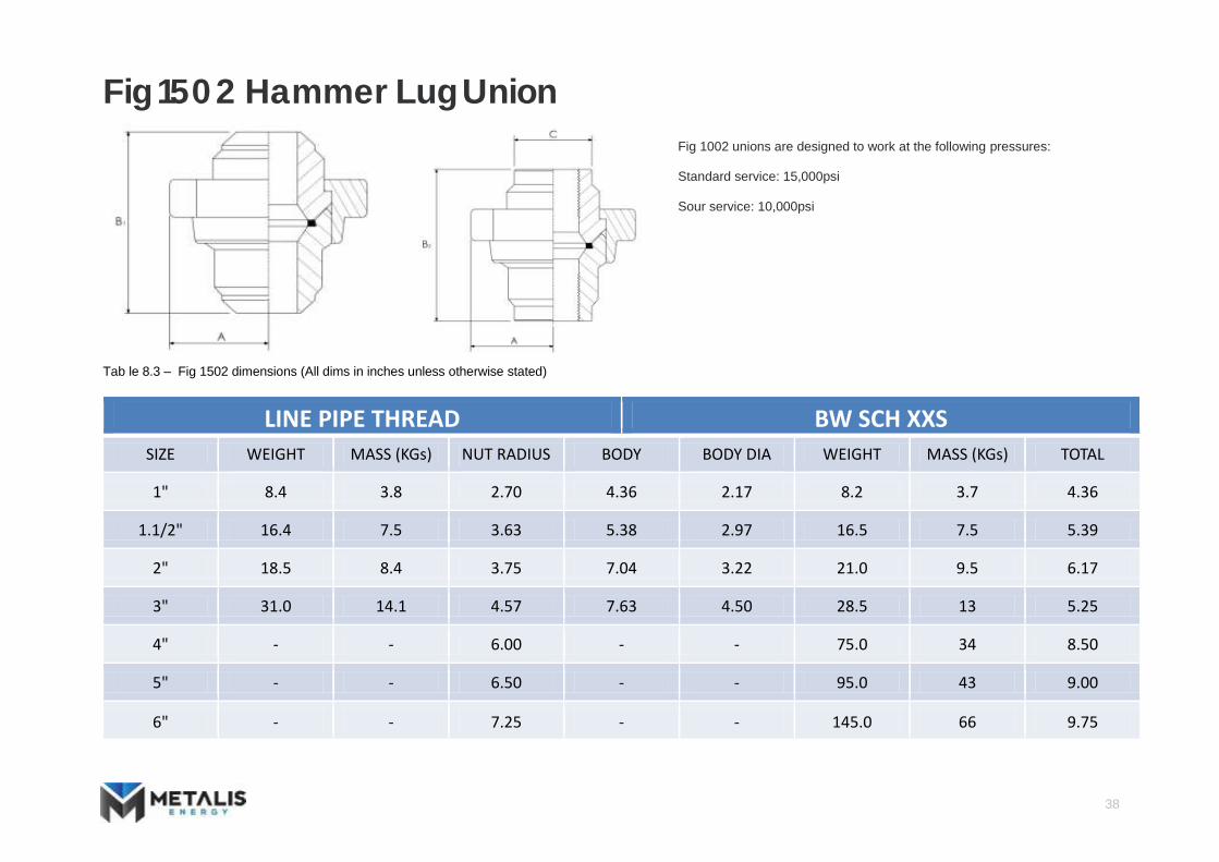
Fig 1502 Hammer Lug Union
Fig 1002 unions are designed to work at the following pressures: Standard service: 15,000psi Sour service: 10,000psi
Tab le 8.3 – Fig 1502 dimensions (All dims in inches unless otherwise stated)
LINE PIPE THREAD BW SCH XXS
SIZE WEIGHT (Lbs)
MASS (KGs) NUT RADIUS (A)
BODY LENGTH
(B2)
BODY DIA (C)
WEIGHT (Lbs)
MASS (KGs) TOTAL LENGTH (B1)
1" 8.4 3.8 2.70 4.36 2.17 8.2 3.7 4.36
1.1/2" 16.4 7.5 3.63 5.38 2.97 16.5 7.5 5.39
2" 18.5 8.4 3.75 7.04 3.22 21.0 9.5 6.17
3" 31.0 14.1 4.57 7.63 4.50 28.5 13 5.25
4" - - 6.00 - - 75.0 34 8.50
5" - - 6.50 - - 95.0 43 9.00
6" - - 7.25 - - 145.0 66 9.75

39
Fig 2202 Hammer Lug Union
Fig 2202 unions are a designed to work at 15,000psi standard or sour service
Table 8.4 – Fig 2202 dimensions (All dims in inches unless otherwise stated)
BUTT WELD WELD PREP
SIZE WEIGHT (Lbs)
MASS (KGs)
NUT RADIUS (A)
TOTAL LENGTH (B)
O/D I/D
2" 23.0 10.5 3.75 7.40 2.50 1.25
3" 48.0 21.8 4.88 9.56 4.125 2.06
4" 76.0 34.5 6.00 8.50 5.50 3.00
5" 110.0 50 6.50 10.75 6.12 4.00
6" 170.0 77.3 7.25 13.00 7.75 5.00

40
API Valves Metalis Energy only supplies the highest quality API 6A Products All products have been designed to be strictly in accordance with the following standards: MSS‐SP75 Specifications for High test Wrought Butt Weld Fittings.
ANSI B31.3 Chemical Plant and Petroleum Refinery Piping. ANSI 16.9 Factory made Wrought Steel Butt Weld Fittings. NACE MR‐01‐75 Sulphide Stress Cracking Resistant Metallic Materials for Oil Field Equipment.
API 6A Specifications for Wellhead and Christmas Tree Equipment. All API 6A valves can be specified with the following:
PSL level 1, 2, 3 or 4 Material Class, AA, BB, CC, DD, EE‐NL
PR‐1 or PR‐2
Temperature classes: K thru Y (‐60degC to 345degC)
See the tables below for the dimensional data of common valve sizes. Please note that these are lists of only the most common sizes stocked by Metalis. If you have any requirements for specific sizes or special materials that are not in the lists please contact [email protected] and we will be more than happy to assist. Metalis are capable of supplying all standard API sizes.

41
API 6A Manual Gate Valve
Table 9.1 – API 6A Manual Gate Valve Dimensions
VALVE SIZE API RING GASKET
BORE DIAMETER
(A)
FACE TO FACE (B)
CENTRELINE TO BASE
(C)
EXTREME BODY
DIAMETER (D)
CENTRELINE TO
HANDWHEEL (E)
HANDWHEEL DIA (F)
TURNS TO OPEN
WEIGHT (KGs)
2-1/16” 5K R-24 2.06” 14.62” 5.88” 7.25” 14.44” 12.00” 13.5 92kg 2-9/16” 5K R-27 2.56” 16.62” 6.50” 7.75” 15.38” 16.00” 15.5 127kg 3-1/8” 5K R-35 3.12” 18.62” 7.88” 9.62” 16.25” 16.00” 18 165kg
4-1/16” 5K R-39 4.06” 21.62” 10.12” 10.75” 17.88” 20.00” 24 262kg 5-1/8” 5K R-44 5.12” 28.62” 13.00” 14.12” 24.12” 24.00” 23.5 686kg
1-13/16” 10K BX-151 1.81” 18.25” 5.30” 8.25” 14.25” 16.00” 12 115kg 2-1/16” 10K BX-152 2.06” 20.50” 5.75” 8.25” 14.44” 16.00” 13.5 118kg 2-9/16” 10K BX-153 2.56” 22.25” 6.88” 9.25” 15.38” 16.00” 15.5 150kg 3-1/16” 10K BX-154 3.06” 24.38” 8.06” 10.25” 16.25” 20.00” 18 230kg 4-1/16” 10K BX-155 4.06” 26.38” 9.88” 12.25” 20.50” 24.00” 24 416kg 5-1/8” 10K BX-169 5.12” 29.00” 13.00” 14.12” 24.12” 24.00” 23.5 670kg

42
API 6A Manual Gate Valve
Table 9.1 – API 6A Manual Gate Valve Dimensions
VALVE SIZE API RING GASKET
BORE DIAMETER
(A)
FACE TO FACE (B)
CENTRELINE TO BASE
(C)
EXTREME BODY
DIAMETER (D)
CENTRELINE TO
HANDWHEEL (E)
HANDWHEEL DIA (F)
TURNS TO OPEN
WEIGHT
1-13/16” 15K BX-151 1.81” 18.00” 5.38” 8.25” 14.25” 16.00” 12 127kg 2-1/16” 15K BX-152 2.06” 19.00” 6.12” 8.25” 14.44” 16.00” 13.5 136kg 2-9/16” 15K BX-153 2.56” 25.00” 7.12” 10.25” 17.88” 20.00” 16 207kg 3-1/16” 15K BX-154 3.06” 23.56” 9.00” 12.00” 19.00” 20.00” 19 380kg 4-1/16” 15K BX-155 4.06” 29.00” 10.50” 13.00” 23.00” 24.00” 20 619kg

43
API 6A Hydraulic Gate Valve
Table 9.2 – API 6A Hydraulic Gate Valve Dimensions
VALVE SIZE API RING GASKET
BORE DIAMETER
(A)
FACE TO FACE (B)
CENTRELINE TO BASE
(C)
EXTREME BODY DIAMETER
(D)
CENTRELINE TO TOP (E)
ACTUATOR DIA (F)
WEIGHT (KGs)
2-1/16” 5K R-24 2.06” 14.62” 6.00” 7.25” 20.50” 7.87” 110
3-1/8” 5K R-35 3.12” 18.62” 7.88” 9.62” 23.45” 7.87” 183
4-1/16” 5K R-39 4.06” 21.62” 10.13” 10.75” 25.97” 7.87” 280
5-1/8” 5K R-44 5.12” 28.62” 13.00” 14.12” 34.12” 11.25” 805
2-1/16” 10K BX-152 2.06” 20.50” 5.75” 8.25” 20.50” 7.87” 134
3-1/16” 10K BX-154 3.06” 24.38” 8.06” 10.25” 23.45” 7.87” 250
4-1/16” 10K BX-155 4.06” 26.38” 10.50” 12.25” 29.78” 10.75” 474
5-1/8” 10K BX-169 5.12” 29.00” 13.00” 14.12” 34.12” 11.25” 789

44
7,500 Psi Mud Valves Butt Weld Ends
Table 9.3 – 7,500 psi Butt Weld End Mud Valve Dimensions
VALVE SIZE BORE DIAMETER,
AT SEAT (A)
END TO END (B)*
CENTRELINE TO BASE
(C)
CENTRELINE TO TOP, MAX
(D)
HANDWHEEL DIA (E)
WEIGHT
2” x 2”SCH XXS 2.00” 14.00” 3.25” 11.88” 14.00” 54kg 3” x 3” SCH XXS 3.00” 16.00” 4.88” 18.13” 18.00” 110kg 4” x 3” SCH XXS 3.00” 16.00” 4.88” 18.13” 18.00” 110kg 5” x 4” SCH XXS 4.00” 16.00” 5.12” 24.63” 23.00” 160kg 6” x 5” SCH XXS 5.00” 17.88” 5.75” 30.64” 26.00” 270kg

45
7,500 PSI Mud Valves API 6A Flanged Ends
Table 9.4 – 7,500 psi API 6A Flanged End Mud Valve Dimensions
VALVE SIZE API 6A FLANGE
SIZE
RTJ TYPE END TO END (A)
CENTRELINE TO BASE
(B)
CENTRELINE TO TOP
(C)
HANDWHEEL DIA (D)
FLANGE DIA (F)
BORE SIZE AT SEAT
WEIGHT
2” 2-1/16” 10K BX-152 13.50” 3.25” 11.88” 14.00” 7.88” 2.00” 70kg 3” 2-9/16” 10K BX-153 22.25” 4.87” 18.13” 18.00” 9.12” 3.00” 155kg 3” 3-1/16” 10K BX-154 27.12” 4.87” 18.13” 18.00” 10.62” 3.00” 162kg 5” 4-1/16” 10K BX-155 29.12” 7.00” 24.63” 23.00” 12.44” 4.00” 250kg 5” 5-1/8” 10K BX-169 29.00” 5.75” 30.64” 26.00” 14.06” 5.13” 375Kg

46
7,500 PSI Mud Valves Hub Ends
Table 9.5– 7,500 Hub End Mud Valve Dimensions
VALVE SIZE
HUB SIZE*
BORE SIZE AT SEAT
END TO END*
(A)
CENTRELINE TO BASE
(B)
CENTRELINE TO TOP
(C)
HANDWHEEL DIA (D)
WEIGHT
2” 2in14 2.00” 14.00” 3.25” 11.88” 14.00” 55kg 3” 4in31 3.00” 20.00” 4.87” 18.13” 18.00” 120kg 4” 5in40 4.00” 24.00” 7.00” 24.63” 23.00” 175kg 5” 6in46 5.13” 20.50” 5.75” 30.64” 26.00” 280kg

47
API 6A Plug Valves Hammer Union Ends
Table 9.6 – API 6A Hammer Union End Plug Valve Dimensions
VALVE SIZE
6 BORE SIZE (A)
END TO END (B)
END TO CENTRE OF PLUG
(C)
HANDWHEEL DIA (D)
CENTRE LINE TO END OF
HANDWHEEL (E)
CENTRELINE TO TOP
(F)
CENTRELINE TO BOTTOM
(G)
WEIGHT
1” 1” FIG 1502 MxF 0.94” 9.50” 5.69” n/a n/a 5.19” 4.56” 19kg 1” 2” FIG 1502 MXF 0.94” 10.56” 5.88” n/a n/a 5.19” 4.56” 25kg 2” 2” FIG 1502 MxF 1.75” 13.88” 7.88” n/a n/a 5.94” 5.50” 45kg 3” 3” FIG 1502 MxF 2.75” 17.52” 9.00” 12.00” 11.75” 6.62” 6.78” 99kg
48
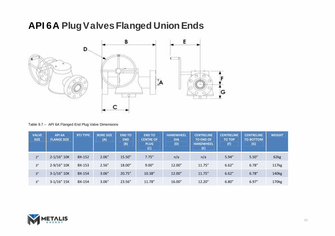
API 6A Plug Valves Flanged Union Ends
Table 9.7 – API 6A Flanged End Plug Valve Dimensions
VALVE SIZE
API 6A FLANGE SIZE
RTJ TYPE BORE SIZE (A)
END TO END (B)
END TO CENTRE OF
PLUG (C)
HANDWHEEL DIA (D)
CENTRELINE TO END OF
HANDWHEEL (E)
CENTRELINE TO TOP
(F)
CENTRELINE TO BOTTOM
(G)
WEIGHT
2” 2-1/16” 10K BX-152 2.06” 15.50” 7.75” n/a n/a 5.94” 5.50” 62kg 3” 2-9/16” 10K BX-153 2.56” 18.00” 9.00” 12.00” 11.75” 6.62” 6.78” 117kg 3” 3-1/16” 10K BX-154 3.06” 20.75” 10.38” 12.00” 11.75” 6.62” 6.78” 140kg 3” 3-1/16” 15K BX-154 3.06” 23.56” 11.78” 16.00” 12.20” 6.80” 6.97” 170kg

49
Pipeline Hubs and Clamps Metalis Energy will only supply the highest quality hubs and clamps designed to be strictly in accordance with the following standards: ASME VIII Div 1:1998 ASME VIII Div 2: Alternative rules: 1998: Appendix 4 ANSI B31.3 Chemical Plant and Petroleum Refinery Piping. ANSI 16.9 Factory made Wrought Steel Butt Weld Fittings. NACE MR‐01‐75 Sulphide Stress Cracking Resistant Metallic Materials for Oil Field Equipment.
See the tables below for the dimensional data of standard Metalis hub and clamp sizes. Please note that these are lists of only the most common sizes stocked by Metalis. If you have any requirements for specific sizes or special materials that are not in the lists please contact [email protected] and we will be more than happy to assist.

50
Pipeline Hubs and Clamps ‐ Standard Series Hubs
Table 10.1 – Standard Series Hubs ‐ Dimensions (all dims in inches unless otherwise stated)
CLAMP SIZE
N.P.S OD (D)
NOMINAL DIA (DN)
PIPE SCH STANDARD DESIGNATION
HUB OUTSIDE
DIA (A)
HUB LENGTH
(B) HUB
BACKFACE DIA (C)
B/W INSIDE
DIA (E)
LIP THICKNESS
(F) BLIND HUD
THICKNESS (G)
BW HUB WEIGHT
(KG) BLIND HUB
WEIGHT (KG)
1/2” DN15 Std 40 40S 1in5 2.00 1.75 1.50 0.62 0.31 1.31 0.3 0.4 1/2” DN15 XS 80 80S 1in5 2.00 1.75 1.50 0.55 0.31 1.31 0.3 0.4 1/2” DN15 160 1in4 2.00 1.75 1.50 0.47 0.31 1.31 0.3 0.4 1/2” DN15 XXS 1in4 2.00 1.75 1.50 0.25 0.31 1.31 0.3 0.4 3/4” DN20 Std 40 40S 1in7 2.00 1.75 1.50 0.82 0.31 1.31 0.2 0.4 3/4” DN20 XS 80 80S 1in7 2.00 1.75 1.50 0.74 0.31 1.31 0.3 0.4
51
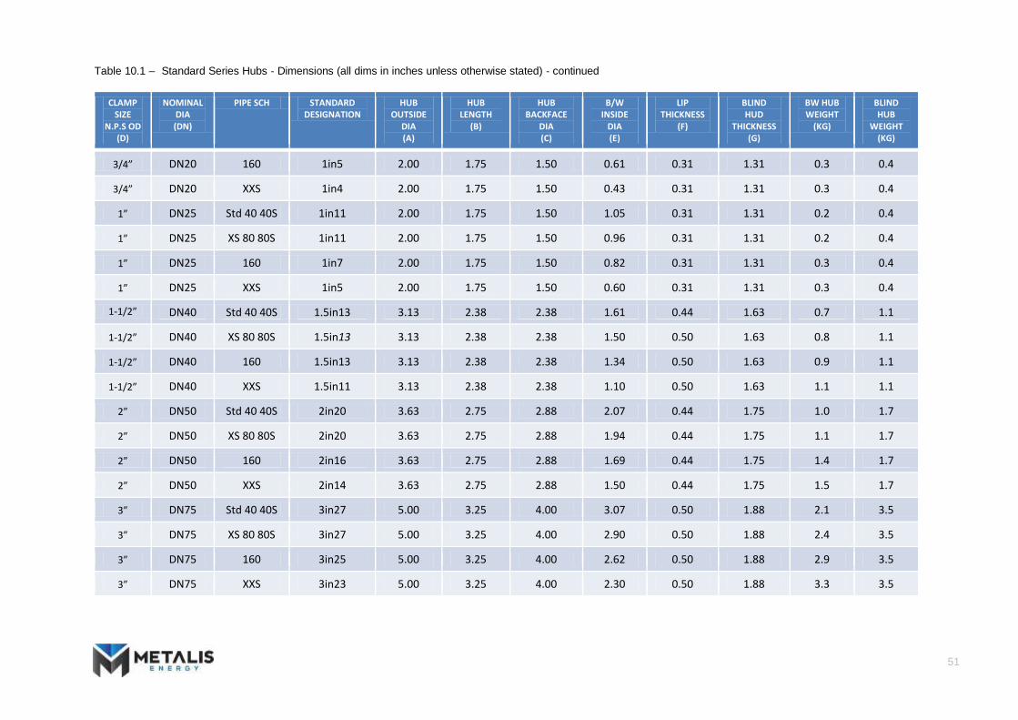
Table 10.1 – Standard Series Hubs ‐ Dimensions (all dims in inches unless otherwise stated) ‐ continued
CLAMP SIZE
N.P.S OD (D)
NOMINAL DIA (DN)
PIPE SCH STANDARD DESIGNATION
HUB OUTSIDE
DIA (A)
HUB LENGTH
(B) HUB
BACKFACE DIA (C)
B/W INSIDE
DIA (E)
LIP THICKNESS
(F) BLIND HUD
THICKNESS (G)
BW HUB WEIGHT
(KG) BLIND HUB
WEIGHT (KG)
3/4” DN20 160 1in5 2.00 1.75 1.50 0.61 0.31 1.31 0.3 0.4 3/4” DN20 XXS 1in4 2.00 1.75 1.50 0.43 0.31 1.31 0.3 0.4 1” DN25 Std 40 40S 1in11 2.00 1.75 1.50 1.05 0.31 1.31 0.2 0.4 1” DN25 XS 80 80S 1in11 2.00 1.75 1.50 0.96 0.31 1.31 0.2 0.4 1” DN25 160 1in7 2.00 1.75 1.50 0.82 0.31 1.31 0.3 0.4 1” DN25 XXS 1in5 2.00 1.75 1.50 0.60 0.31 1.31 0.3 0.4
1-1/2” DN40 Std 40 40S 1.5in13 3.13 2.38 2.38 1.61 0.44 1.63 0.7 1.1 1-1/2” DN40 XS 80 80S 1.5in13 3.13 2.38 2.38 1.50 0.50 1.63 0.8 1.1 1-1/2” DN40 160 1.5in13 3.13 2.38 2.38 1.34 0.50 1.63 0.9 1.1 1-1/2” DN40 XXS 1.5in11 3.13 2.38 2.38 1.10 0.50 1.63 1.1 1.1
2” DN50 Std 40 40S 2in20 3.63 2.75 2.88 2.07 0.44 1.75 1.0 1.7 2” DN50 XS 80 80S 2in20 3.63 2.75 2.88 1.94 0.44 1.75 1.1 1.7 2” DN50 160 2in16 3.63 2.75 2.88 1.69 0.44 1.75 1.4 1.7 2” DN50 XXS 2in14 3.63 2.75 2.88 1.50 0.44 1.75 1.5 1.7 3” DN75 Std 40 40S 3in27 5.00 3.25 4.00 3.07 0.50 1.88 2.1 3.5 3” DN75 XS 80 80S 3in27 5.00 3.25 4.00 2.90 0.50 1.88 2.4 3.5 3” DN75 160 3in25 5.00 3.25 4.00 2.62 0.50 1.88 2.9 3.5 3” DN75 XXS 3in23 5.00 3.25 4.00 2.30 0.50 1.88 3.3 3.5

52
Table 10.1 – Standard Series Hubs ‐ Dimensions (all dims in inches unless otherwise stated) ‐ continued
CLAMP SIZE
N.P.S OD (D)
NOMINAL DIA (DN)
PIPE SCH STANDARD DESIGNATION
HUB OUTSIDE
DIA (A)
HUB LENGTH
(B) HUB
BACKFACE DIA (C)
B/W INSIDE
DIA (E)
LIP THICKNESS
(F) BLIND HUD
THICKNESS (G)
BW HUB WEIGHT
(KG) BLIND HUB
WEIGHT (KG)
4” DN100 Std 40 40S 4in40 6.00 3.63 5.00 4.03 0.50 2.13 3.1 5.9 4” DN100 XS 80 80S 4in40 6.00 3.63 5.00 3.83 0.50 2.13 3.5 5.9 4” DN100 160 4in34 6.00 3.63 5.00 3.44 0.50 2.13 4.5 5.9 4” DN100 XXS 4in31 6.00 3.63 5.00 3.15 0.50 2.13 5.2 5.9 5” DN125 Std 40 40S 5in52 7.50 4.38 6.50 5.05 0.63 2.75 6.0 12.6 5” DN125 XS 80 80S 5in52 7.50 4.38 6.50 4.81 0.63 2.75 6.7 12.6 5” DN125 160 5in46 7.50 4.38 6.50 4.31 0.63 2.75 8.7 12.6 5” DN125 XXS 5in40 7.50 4.38 6.50 4.06 0.63 2.75 9.9 12.6 6” DN150 Std 40 40S 6in62 9.25 4.63 7.75 6.07 0.75 2.88 9.2 19.5 6” DN150 XS 80 80S 6in56 9.25 4.63 7.75 5.76 0.81 2.88 11.3 19.5 6” DN150 120 6in54 9.25 4.63 7.75 5.50 0.81 2.88 12.6 19.5 6” DN150 160 6in52 9.25 4.63 7.75 5.19 0.81 2.88 13.9 19.5 6” DN150 XXS 6in52 9.25 4.63 7.75 4.90 0.81 2.88 14.8 19.5 8” DN200 Std 40 40S 8in82 11.50 5.38 10.00 7.98 0.75 3.19 15.0 34.6 8” DN200 XS 80 80S 8in76 11.50 5.38 10.00 7.63 0.75 3.19 18.3 34.6 8” DN200 100 8in76 11.50 5.38 10.00 7.44 0.75 3.19 19.2 34.6 8” DN200 120 8in72 11.50 5.38 10.00 7.19 0.75 3.19 21.7 34.6 8” DN200 140 8in72 11.50 5.38 10.00 7.00 0.75 3.19 22.6 34.6 8” DN200 XXS 8in67 11.50 5.38 10.00 6.88 0.75 3.19 24.0 34.6 8” DN200 160 8in67 11.50 5.38 10.00 6.81 0.75 3.19 24.3 34.6

53
Pipeline Hubs and Clamps ‐ Standard Series Seal Rings
Table 10.3 – Standard Series Clamps ‐ Dimensions (all dims in inches unless otherwise stated)
CLAMP SIZE
CLAMP ID (A)
BOLT CENTRES
(B) CLAMP
OD (C)
OVERALL LENGTH
(D) CLAMP WIDTH
(E) LUG
SEPERATION (F)
CLAMP CLEARENCE
(G) BOLT
DIAMETER (H)
BOLT LENGTH
(I) BOLT LUG
WIDTH (J)
BOLT PITCH
(K) ASSEMBLY CLEARENCE
(L) ASSEMBLY
WIEGTH (KG)
1in 1.69 3.25 2.81 4.25 1.38 2.19 2.63 0.50 3.50 2.25 1.25 1.91 1.9
1-1/2in 2.69 5.00 4.50 6.50 2.00 3.25 4.00 0.63 5.00 3.13 1.63 3.02 4.5
2in 3.20 5.75 5.50 7.50 2.00 3.52 4.50 0.75 5.25 3.38 1.81 3.59 6.0
3in 4.38 7.50 6.88 9.25 2.38 4.60 5.25 0.75 6.50 3.38 1.81 4.63 10.7
4in 5.38 8.50 8.25 10.50 2.38 5.40 6.00 0.88 7.50 4.00 2.06 5.39 13.0
5in 6.88 10.25 9.88 12.38 3.13 6.13 7.25 1.00 8.25 4.50 2.31 6.38 18.6
6in 8.38 12.63 12.00 15.25 3.75 6.88 8.75 1.13 10.63 5.25 2.44 7.96 31.9
8in 10.63 15.25 14.50 18.50 3.75 7.88 9.88 1.25 12.00 5.75 2.88 9.39 50.0

54
Table 10.2 – Standard Series Seal Rings ‐ Dimensions (all dims in inches unless otherwise stated) ‐ continued
SEAL RING OUTSIDE DIAMETER (A)
INSIDE DIAMETER (B)
OVERALL THICKNESS (C)
RIB THICKNESS (D)
SEAL RING WIEGHT (KG)
31 4.500 3.250 0.750 0.250 0.31
34 5.000 3.688 0.750 0.250 0.36
40 5.500 4.063 1.000 0.250 0.51
42 6.375 4.188 1.000 0.250 0.76
46 6.250 4.750 1.000 0.250 0.61
52 6.625 5.313 1.000 0.250 0.60
54 6.812 5.500 1.000 0.250 0.71 56 7.500 5.750 1.000 0.250 0.83
62 7.875 6.065 1.375 0.375 1.42
64 8.625 6.500 1.375 0.375 1.72
67 8.750 6.875 1.375 0.375 1.64
72 9.500 7.250 1.375 0.375 2.00
76 10.000 7.750 1.375 0.375 2.12
82 10.125 8.250 1.375 0.375 1.93

55
Pipeline Hubs and Clamps ‐ Standard Series Clamp
Table 10.2 – Standard Series Seal Rings ‐ Dimensions (all dims in inches unless otherwise stated)
SEAL RING OUTSIDE DIAMETER (A)
INSIDE DIAMETER (B)
OVERALL THICKNESS (C)
RIB THICKNESS (D)
SEAL RING WIEGHT (KG)
4 1.000 0.500 0.375 0.125 0.01 5 1.094 0.625 0.375 0.125 0.01 7 1.375 0.906 0.375 0.125 0.02
11 1.750 1.125 0.375 0.125 0.03 13 2.375 1.500 0.375 0.125 0.05 14 2.625 1.609 0.563 0.250 0.13 16 2.750 1.868 0.625 0.250 0.13 20 3.250 2.063 0.750 0.250 0.20
23 3.500 2.375 0.750 0.250 0.22 25 4.000 2.672 0.750 0.250 0.28 27 4.250 3.063 0.750 0.250 0.28

56
API 16C Hubs and Clamps Metalis Energy only supplies the highest quality API 16 Products manufactured in UK. They have been designed to be strictly in accordance with the following standards: MSS‐SP75 Specifications for High test Wrought Butt Weld Fittings.
ANSI B31.3 Chemical Plant and Petroleum Refinery Piping. ANSI 16.9 Factory made Wrought Steel Butt Weld Fittings. NACE MR‐01‐75 Sulphide Stress Cracking Resistant Metallic Materials for Oil Field Equipment.
API 16A Specifications for Drill Through Equipment. See the tables below for the dimensional data of standard Metalis hub sizes. Please note that these are lists of only the most common sizes stocked by Metalis. If you have any requirements for specific sizes or special materials that are not in the lists please contact [email protected] and we will be more than happy to assist. Metalis are capable of supplying all API sizes.

57
5,000 PSI API 16C Hubs and Clamps
Table 11.1 – 5,000 psi API 16C Hubs & Clamps Dimensions (all dims in inches unless otherwise stated)
NOMINAL BORE SIZE (B)
OUTSIDE DIAMETER (D)
LIP THICKNESS (C)
LARGE DIAMETER OF HUB (A)
MIN LENGTH OF HUB (E)
RING GASKET NUMBER
CLAMP NUMBER
2-1/16” 5.031 1.166 3.656 2.22 BX-152 1
2-9/16” 5.781 1.166 4.406 2.27 BX-153 2
3-1/8” 6.312 1.166 4.938 2.36 BX-154 4
4-1/16” 7.625 1.197 6.250 2.38 BX-155 5
7-1/16” 13.250 1.622 11.625 3.38 BX-156 6

58
10,000 PSI API 16C Hubs and Clamps
Table 11.1 – 10,000 psi API 16C Hubs & Clamps Dimensions (all dims in inches unless otherwise stated)
NOMINAL BORE SIZE (B)
OUTSIDE DIAMETER (D)
LIP THICKNESS (C)
LARGE DIAMETER OF HUB (A)
MIN LENGTH OF HUB (E)
RING GASKET NUMBER
CLAMP NUMBER
1-13/16” 5.031 1.166 3.656 2.22 BX-151 1
2-1/16” 5.781 1.166 4.406 2.27 BX-152 2
2-9/16” 6.312 1.166 4.938 2.36 BX-153 4
3-1/16” 7.625 1.197 6.250 2.38 BX-154 5
4-1/16” 8.437 1.310 6.812 2.82 BX-155 6
7-1/16” 16.250 1653 14.625 4.13 BX-156 10

59
15,000 PSI API 16C Hubs and Clamps
Table 11.1 – 15,000 psi API 16C Hubs & Clamps Dimensions (all dims in inches unless otherwise stated)
NOMINAL BORE SIZE (B)
OUTSIDE DIAMETER (D)
LIP THICKNESS (C)
LARGE DIAMETER OF HUB (A)
MIN LENGTH OF HUB (E)
RING GASKET NUMBER
CLAMP NUMBER
1-13/16” 5.781 1.166 4.406 2.27 BX-151 2
2-1/16” 6.125 1.622 4.500 3.22 BX-152 3
2-9/16” 6.125 1.622 4.500 3.22 BX-153 3
3-1/16” 8.437 1.310 6.812 2.82 BX-154 6
4-1/16” 13.250 1.622 11.625 3.38 BX-155 8
7-1/16” 20.626 2.035 18.625 4.75 BX-156 22

60
Metalis Energy Ltd
Unit 1 Birchwood Way, Ashwood Business Park, Ashington, Northumberland, NE63 0XD. Registered in the UK: 06758233
metalisenergy.com


![13 Edition - Bicakcilarapi.bicakcilar.com/Storage/ProductGroup/EngPdf/90a... · [dafa[Yd ljaYdk$ Yf\ kmhhda]k l`]k] lg ]f\%mk]jk$ Yf\ l`mk hagf]]jk l`] afljg\m[lagf g^ f]o hjg\m[lk](https://img.pdfslide.us/doc/110x75/600c8faeb04cb449c10a0527/13-edition-dafayd-ljaydk-yf-kmhhdak-lk-lg-fmkjk-yf-lmk-hagfjk.jpg)
