Embed Size (px)
Citation preview
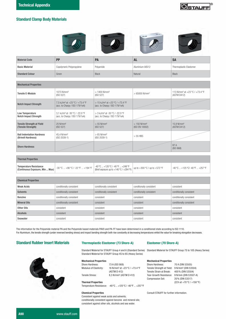
Technical Appendix
Material Code PP PA AL SA
Basic Material Copolymeric Polypropylene Polyamide Aluminium AlSi12 Thermoplastic Elastomer
Standard Colour Green Black Natural Black
Mechanical Properties
Tensile E-Module 1073 N/mm² (ISO 527)
> 1400 N/mm² (ISO 527)
> 65000 N/mm² 113 N/mm² at +23 °C / +73.4 °F (ASTM D412)
Notch Impact Strength 7,5 kJ/m² at +23 °C / +73.4 °F(acc. to Charpy / ISO 179/1eA)
> 15 kJ/m² at +23 °C / +73.4 °F(acc. to Charpy / ISO 179/1eA)
Low TemperatureNotch Impact Strength
3,1 kJ/m² at -30 °C / -22.0 °F(acc. to Charpy / ISO 179/1eA)
> 3 kJ/m² at -30 °C / -22.0 °F(acc. to Charpy / ISO 179/1eA)
Tensile Strength at Yield(Tensile Strength)
25 N/mm² (ISO 527)
> 55 N/mm² (ISO 527)
> 150 N/mm² (ISO EN 10002)
15,9 N/mm² (ASTM D412)
Ball Indentation Hardness(Brinell Hardness)
45,4 N/mm² (ISO 2039-1)
> 65 N/mm² (ISO 2039-1) > 55 HBS
Shore Hardness 87 A(ISO 868)
Standard Clamp Body Materials
Thermal Properties
Temperature Resistance (Continuous Exposure, Min ... Max) -30 °C ... +90 °C / -22 °F ... +194 °F -40 °C ... +120 °C / -40 °F ... +248 °F
(Brief exposure up to +140 °C / +284 °F) up to +300 °C / up to +572 °F -40 °C ... +125 °C/ -40 °F ... +257 °F
Chemical Properties
Weak Acids conditionally consistent conditionally consistent conditionally consistent consistent
Solvents conditionally consistent conditionally consistent conditionally consistent conditionally consistent
Benzine conditionally consistent consistent consistent conditionally consistent
Mineral Oils conditionally consistent consistent consistent conditionally consistent
Other Oils consistent consistent consistent consistent
Alcohols consistent consistent consistent consistent
Seawater consistent consistent consistent consistent
The information for the Polyamide material PA and the Polyamide based materials PAV0 and PA-FF have been determined in a conditioned state according to ISO 1110.For Aluminium, the tensile strength (under reversed bending stress) and impact bending strength both rise constantly at decreasing temperatures whilst the value for breaking elongation decreases.
Thermoplastic Elastomer (73 Shore-A)
Standard Material for STAUFF Group 4 and 6 (Standard Series)Standard Material for STAUFF Group 4S to 6S (Heavy Series)
Mechanical PropertiesShore Hardness: 73 A (ISO 868)Modulus of Elasticity: 16 N/mm² at +23 °C / +73.4 °F (ASTM D 412)Tensile Stress: 8,3 N/mm² (ASTM D 412)
Thermal PropertiesTemperature Resistance: -40 °C ... +125 °C / -40 °F ... +257 °F
Chemical PropertiesConsistent against weak acids and solvents; conditionally consistent against benzine and mineral oils;consistent against other oils, alcohols and sea water.
Standard Rubber Insert Materials Elastomer (70 Shore-A)
Standard Material for STAUFF Group 7S to 10S (Heavy Series)
Mechanical PropertiesShore Hardness: 70 A (DIN 53505)Tensile Strength at Yield: 9 N/mm² (DIN 53504)Tensile Strain at Break: 400 % (DIN 53504)Tear-Growth Resistance: 9 N/mm (DIN 53507-A)Compression Set: 20 % (DIN 53517) (22 h at +70 °C / +158 °F)
Consult STAUFF for further information.
A90 www.stauff.com
Schelle-2012-03-28-EN.indd 90 29.03.2012 10:13:13
STAU
FF
Clam
psA
Approvals / Special Properties
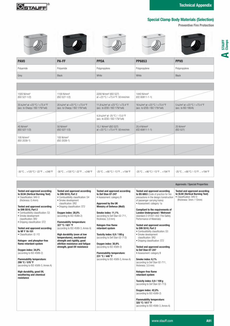
Tested and approved according to UL94 (Vertical Burning Test)� Classification: 94V-0 (thickness: 0,4mm)
Tested and approved according to DIN 5510, Part 2� Combustibility classification: S3� Smoke development classification: SR2� Dripping classification: ST2
Tested and approved according to NF F 16-101� Classification: I2 / F2
Halogen- and phosphor-free flame retardant system
Oxygen index: 34,0% (according to ISO 4589-2)
Flammability temperature: 299 °C / 570 °F(according to ISO 4589-3, Annex A)
High durability, good UV, weathering and chemical resistance
Tested and approved according to DIN 5510, Part 2� Combustibility classification: S4� Smoke development classification: SR2� Dripping classification: ST2
Oxygen index: 28,0% (according to ISO 4589-2)
Flammability temperature: 327 °C / 621 °F(according to ISO 4589-3, Annex A)
High durability (even at low temperatures), mechanical strength and rigidity, good attrition resistance and fatigue strength, good UV resistance
Tested and approved according to Def Stan 07-247� Assessment: category B
Approved by the UK Ministry of Defence (MoD)
Smoke index: 11,1% (according to Def Stan 02-711, thickness: 3,0 mm)
Halogen-free flame retardant system
Toxicity index: 0,9 / 100 g (according to Def Stan 02-713)
Oxygen index: 30,9% (according to ISO 4589-2)
Flammability temperature: 231 °C / 448 °F(according to ISO 4589-3, Annex A)
Tested and approved according to BS 6853 (Code of practice for fire precautions in the design / construction of passenger carrying trains)� Assessment: category 1a
Compliant to the requirements of London Underground / Metronet(standard 2-01001-002: Fire Safety Performance of Materials)
Tested and approved according to DIN 5510, Part 2� Combustibility classification: S3� Smoke development classification: SR2� Dripping classification: ST2
Tested and approved according to Def Stan 07-247� Assessment: category B
Smoke index: 6,1% (according to Def Stan 02-711, thickness: 3,0 mm)
Halogen-free flame retardant system
Toxicity index: 0,9 / 100 g (according to Def Stan 02-713)
Oxygen index: 42,0% (according to ISO 4589-2)
Flammability temperature: 325 °C / 617 °F(according to ISO 4589-3, Annex A)
Tested and approved according to UL94 (Vertical Burning Test)� Classification: 94V-0 (thickness: 3mm / 13mm)
Technical Appendix
PAV0 PA-FF PPDA PP6853 PPV0
Polyamide Polyamide Polypropylene Polypropylene Polypropylene
Grey Black White White Black
1500 N/mm² (ISO 527-1/2)
1100 N/mm² (ISO 527-1/2)
2200 N/mm² (ISO 527) at +23 °C / +73.4 °F: 50 mm/min
1440 N/mm² (ICE 60811-1-1)
35 kJ/m² at +23 °C / +73.4 °F(acc. to Charpy / ISO 179/1eA)
20 kJ/m² at +23 °C / +73.4 °F(acc. to Charpy / ISO 179/1eA)
11,8 kJ/m² at +23 °C / +73.4 °F(acc. to IZOD / ISO 179/1eA)
16 kJ/m² at +23 °C / +73.4 °F(acc. to IZOD / ISO 179/1eA)
5 kJ/m² at +23 °C / +73.4 °F(acc. to ISO 180/A)
4,9 kJ/m² at -25 °C / -13.0 °F(acc. to IZOD / ISO 179/1eA)
45 N/mm² (ISO 527-1/2)
50 N/mm² (ISO 527-1/2)
15,1 N/mm² (ISO 527) at +23 °C / +73.4 °F: 50 mm/min
20,4 N/mm² (ICE 60811-1-1)
25 N/mm² (ISO 527)
100 N/mm² (ISO 2039-1)
100 N/mm² (ISO 2039-1)
-30 °C ... +120 °C / -22 °F ... +248 °F -30 °C ... +120 °C / -22 °F ... +248 °F -25 °C ... +90 °C / -13 °F ... +194 °F -25 °C ... +90 °C / -13 °F ... +194 °F -25 °C ... +90 °C / -13 °F ... +194 °F
Special Clamp Body Materials (Selection)Preventive Fire Protection
www.stauff.com A91
Schelle-2012-03-28-EN.indd 91 29.03.2012 10:13:14
Technical Appendix
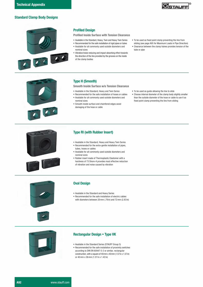
Standard Clamp Body Designs
Profiled DesignProfiled Inside Surface with Tension Clearance
� Available in the Standard, Heavy, Twin and Heavy Twin Series � Recommended for the safe installation of rigid pipes or tubes � Available for all commonly used outside diameters and nominal sizes
� Vibration/noise reducing and impact absorbing effect towards the direction of the line provided by the grooves on the inside of the clamp bodies
Type H (Smooth)Smooth Inside Surface w/o Tension Clearance
� Available in the Standard, Heavy and Twin Series � Recommended for the safe installation of hoses or cables � Available for all commonly used outside diameters and nominal sizes
� Smooth inside surface and chamfered edges avoid damaging of the hose or cable
� To be used as fixed point clamp preventing the line from sliding (see page A95 for Maximum Loads in Pipe Direction)
� Clearance between the clamp halves provides tension of the tube or pipe
� To be used as guide allowing the line to slide � Choose internal diameter of the clamp body slightly smaller than the outside diameter of the hose or cable to use it as fixed point clamp preventing the line from sliding
Type RI (with Rubber Insert)
� Available in the Standard, Heavy and Heavy Twin Series � Recommended for the extra-gentle installation of pipes, tubes, hoses or cables
� Available for all commonly used outside diameters and nominal sizes
� Rubber insert made of Thermoplastic Elastomer with a hardness of 73 Shore-A provides most effective reduction of vibration and noise caused by vibration
Oval Design
� Available in the Standard and Heavy Series � Recommended for the safe installation of electric cables with diameters between 20 mm (.79 in) and 72 mm (2.83 in)
Rectangular Design � Type VK
� Available in the Standard Series (STAUFF Group 5) � Recommended for the safe installation of proximity switches according to DIN EN 60947-5-2 or similar, rectangular construction, with a square of 40 mm x 40 mm (1.57 in x 1.57 in) or 40 mm x 36 mm (1.57 in x 1.42 in)
A92 www.stauff.com
Schelle-2012-03-28-EN.indd 92 29.03.2012 10:13:16
STAU
FF
Clam
psA
Technical Appendix
Materials and Surface Finishings of Metal Parts
Materials
Unless otherwise stated, all metal parts (e.g. weld plates, cover plates, bolts, rail nuts, etc.) are made of Carbon Steel (surface finishing according to material code).
Besides that, all metal parts are also available ex stock in two different stainless steel qualities:
Stainless Steel V2A � 1.4301 / 1.4305 (AISI 304 / 303) � Material code: W4
Stainless Steel V4A � 1.4401 / 1.4571 (AISI 316 / 316 Ti) � Material code: W5
Alternative materials are available upon request. Consult STAUFF for further information.
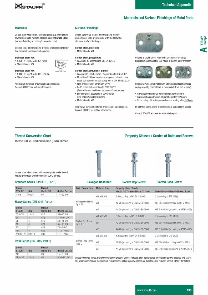
Surface Finishings
Unless otherwise stated, all metal parts made of Carbon Steel St37 are available with the following standard surface finishings:
Carbon Steel, untreated � Material code: W1
Carbon Steel, phosphated � Fe/Znph r 10 according to DIN EN 12476 � Material code: W2
Carbon Steel, zinc/nickel-plated � Fe/ZnNi (12...16) 6+6//A//T2 according to DIN 50962 � More than 720 hours resistance against red rust / base metal corrosion in the salt spray test to DIN EN ISO 9227
� Free of hexavalent chromium Cr(VI) � RoHS compliant according to 2002/95/EC (Restrictions of the Use of Hazardous Substances)
� ELV compliant according to 2000/53/EC (End of Life Vehicles Directive)
� Material code: W3
Alternative surface finishings are available upon request. Consult STAUFF for further information.
Original STAUFF Cover Plate with Zinc/Nickel-Coating:No signs of corrosion after 528 hours in the salt spray chamber!
Original STAUFF Cover Plates with alternative surface finishings widely-used by competitors in the market (from left to right):
� Galvanisation and blue-chromating after 96 hours � Galvanisation and yellow-chromating after 192 hours � Zinc-coating, thick-film passivation and sealing after 192 hours
In all three cases, signs of corrosion are quite clearly visible!
Consult STAUFF and ask for a detailed report.
Property Classes / Grades of Bolts and Screws
Bolt / Screw Type Material Code Property Class / GradeMetric ISO Threaded Bolts / Screws Unified Coarse Threaded Bolts / Screws
Hexagon Head BoltType AS
W1, W2, W3 8.8 (according to DIN EN ISO 898) 5 (according to SAE J429)
W4 A2-70 (according to DIN EN ISO 3506) AISI 304 / B8 (according to ASTM A193)
W5 A4-70 (according to DIN EN ISO 3506) AISI 316 / B8M (according to ASTM A193)
Socket Cap Screw Type IS
W1, W2, W3 8.8 (according to DIN EN ISO 898) 5 (according to SAE J429)
W4 A2-70 (according to DIN EN ISO 3506) AISI 304 / B8 (according to ASTM A193)
W5 A4-70 (according to DIN EN ISO 3506) AISI 316 / B8M (according to ASTM A193)
Slotted Head ScrewType LI
W1, W2, W3 4.8 (according to DIN EN ISO 898) 2 (according to SAE J429)
W4 A2-70 (according to DIN EN ISO 3506) AISI 304 / B8 (according to ASTM A193)
W5 A4-70 (according to DIN EN ISO 3506) AISI 316 / B8M (according to ASTM A193)
Unless otherwise stated, the above mentioned property classes / grades apply as standards for bolts and screws supplied by STAUFF. The information indicate the minimum requirements; higher property classes are available upon request. Consult STAUFF for details.
Thread Conversion Chart Metric ISO vs. Unified Coarse (UNC) Thread
Group ThreadSTAUFF DIN Metric ISO Unified Coarse1 to 8 0 to 8 M6 1/4–20 UNC
Standard Series (DIN 3015, Part 1)
Heavy Series (DIN 3015, Part 2)
Group ThreadSTAUFF DIN Metric ISO Unified Coarse3S to 5S 1 to 3 M10 3/8–16 UNC6S 4 M12 7/16–14 UNC7S 5 M16 5/8–11 UNC8S 6 M20 3/4–10 UNC9S 7 M24 7/8–9 UNC10S 8 M30 1-1/8–7 UNC11S to 12S 9 to 10 M30 1-1/4–7 UNC
Twin Series (DIN 3015, Part 3)
Group ThreadSTAUFF DIN Metric ISO Unified Coarse1D 1 M6 1/4–20 UNC2D to 5D 2 to 5 M8 5/16–18 UNC
Unless otherwise stated, all threaded parts available with Metric ISO thread or unified coarse (UNC) thread.
Hexagon Head Bolt Slotted Head ScrewSocket Cap Screw
www.stauff.com A93
Schelle-2012-03-28-EN.indd 93 29.03.2012 10:13:17
Technical Appendix
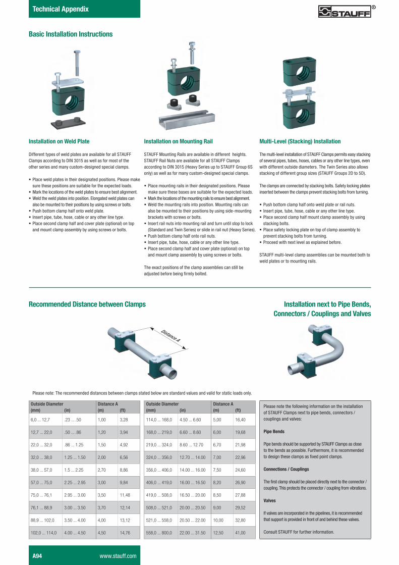
Outside Diameter Distance A(mm) (in) (m) (ft)
114,0 ... 168,0 4.50 ... 6.60 5,00 16,40
168,0 ... 219,0 6.60 ... 8.60 6,00 19,68
219,0 ... 324,0 8.60 ... 12.70 6,70 21,98
324,0 ... 356,0 12.70 ... 14.00 7,00 22,96
356,0 ... 406,0 14.00 ... 16.00 7,50 24,60
406,0 ... 419,0 16.00 ... 16.50 8,20 26,90
419,0 ... 508,0 16.50 ... 20.00 8,50 27,88
508,0 ... 521,0 20.00 ... 20.50 9,00 29,52
521,0 ... 558,0 20.50 ... 22.00 10,00 32,80
558,0 ... 800,0 22.00 ... 31.50 12,50 41,00
Outside Diameter Distance A(mm) (in) (m) (ft)
6,0 ... 12,7 .23 ... .50 1,00 3,28
12,7 ... 22,0 .50 ... .86 1,20 3,94
22,0 ... 32,0 .86 ... 1.25 1,50 4,92
32,0 ... 38,0 1.25 ... 1.50 2,00 6,56
38,0 ... 57,0 1.5 ... 2.25 2,70 8,86
57,0 ... 75,0 2.25 ... 2.95 3,00 9,84
75,0 ... 76,1 2.95 ... 3.00 3,50 11,48
76,1 ... 88,9 3.00 ... 3.50 3,70 12,14
88,9 ... 102,0 3.50 ... 4.00 4,00 13,12
102,0 ... 114,0 4.00 ... 4.50 4,50 14,76
Recommended Distance between Clamps
Basic Installation Instructions
Installation on Weld Plate
Different types of weld plates are available for all STAUFF Clamps according to DIN 3015 as well as for most of the other series and many custom-designed special clamps.
� Place weld plates in their designated positions. Please make sure these positions are suitable for the expected loads.
� Mark the locations of the weld plates to ensure best alignment. � Weld the weld plates into position. Elongated weld plates can also be mounted to their positions by using screws or bolts.
� Push bottom clamp half onto weld plate. � Insert pipe, tube, hose, cable or any other line type. � Place second clamp half and cover plate (optional) on top and mount clamp assembly by using screws or bolts.
Installation on Mounting Rail
STAUFF Mounting Rails are available in different heights. STAUFF Rail Nuts are available for all STAUFF Clamps according to DIN 3015 (Heavy Series up to STAUFF Group 6S only) as well as for many custom-designed special clamps.
� Place mounting rails in their designated positions. Please make sure these bases are suitable for the expected loads.
� Mark the locations of the mounting rails to ensure best alignment. � Weld the mounting rails into position. Mounting rails can also be mounted to their positions by using side-mounting brackets with screws or bolts.
� Insert rail nuts into mounting rail and turn until stop to lock (Standard and Twin Series) or slide in rail nut (Heavy Series).
� Push bottom clamp half onto rail nuts. � Insert pipe, tube, hose, cable or any other line type. � Place second clamp half and cover plate (optional) on top and mount clamp assembly by using screws or bolts.
The exact positions of the clamp assemblies can still be adjusted before being firmly bolted.
Multi-Level (Stacking) Installation
The multi-level installation of STAUFF Clamps permits easy stacking of several pipes, tubes, hoses, cables or any other line types, even with different outside diameters. The Twin Series also allows stacking of different group sizes (STAUFF Groups 2D to 5D).
The clamps are connected by stacking bolts. Safety locking plates inserted between the clamps prevent stacking bolts from turning.
� Push bottom clamp half onto weld plate or rail nuts. � Insert pipe, tube, hose, cable or any other line type. � Place second clamp half mount clamp assembly by using stacking bolts.
� Place safety locking plate on top of clamp assembly to prevent stacking bolts from turning.
� Proceed with next level as explained before.
STAUFF multi-level clamp assemblies can be mounted both to weld plates or to mounting rails.
Please note: The recommended distances between clamps stated below are standard values and valid for static loads only.
Please note the following information on the installation of STAUFF Clamps next to pipe bends, connectors / couplings and valves: Pipe Bends
Pipe bends should be supported by STAUFF Clamps as close to the bends as possible. Furthermore, it is recommended to design these clamps as fixed point clamps.
Connections / Couplings
The first clamp should be placed directly next to the connector / coupling. This protects the connector / coupling from vibrations.
Valves
If valves are incorporated in the pipelines, it is recommended that support is provided in front of and behind these valves.
Consult STAUFF for further information.
Installation next to Pipe Bends, Connectors / Couplings and Valves
Distance A
A94 www.stauff.com
Schelle-2012-03-28-EN.indd 94 29.03.2012 10:13:19
STAU
FF
Clam
psA
Technical Appendix
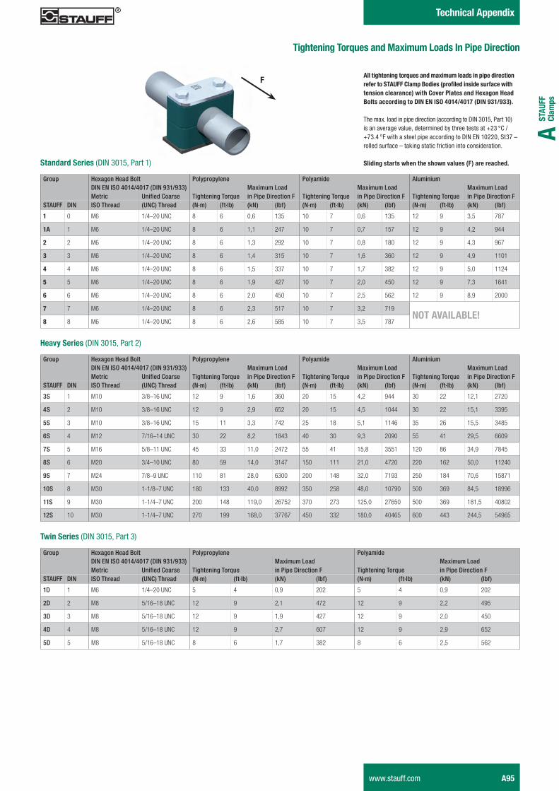
Tightening Torques and Maximum Loads In Pipe Direction
Group Hexagon Head Bolt Polypropylene Polyamide AluminiumDIN EN ISO 4014/4017 (DIN 931/933) Maximum Load Maximum Load Maximum LoadMetric Unified Coarse Tightening Torque in Pipe Direction F Tightening Torque in Pipe Direction F Tightening Torque in Pipe Direction F
STAUFF DIN ISO Thread (UNC) Thread (N·m) (ft·lb) (kN) (lbf) (N·m) (ft·lb) (kN) (lbf) (N·m) (ft·lb) (kN) (lbf)
1 0 M6 1/4–20 UNC 8 6 0,6 135 10 7 0,6 135 12 9 3,5 787
1A 1 M6 1/4–20 UNC 8 6 1,1 247 10 7 0,7 157 12 9 4,2 944
2 2 M6 1/4–20 UNC 8 6 1,3 292 10 7 0,8 180 12 9 4,3 967
3 3 M6 1/4–20 UNC 8 6 1,4 315 10 7 1,6 360 12 9 4,9 1101
4 4 M6 1/4–20 UNC 8 6 1,5 337 10 7 1,7 382 12 9 5,0 1124
5 5 M6 1/4–20 UNC 8 6 1,9 427 10 7 2,0 450 12 9 7,3 1641
6 6 M6 1/4–20 UNC 8 6 2,0 450 10 7 2,5 562 12 9 8,9 2000
7 7 M6 1/4–20 UNC 8 6 2,3 517 10 7 3,2 719NOT AVAILABLE!
8 8 M6 1/4–20 UNC 8 6 2,6 585 10 7 3,5 787
All tightening torques and maximum loads in pipe direction refer to STAUFF Clamp Bodies (profiled inside surface with tension clearance) with Cover Plates and Hexagon Head Bolts according to DIN EN ISO 4014/4017 (DIN 931/933).
The max. load in pipe direction (according to DIN 3015, Part 10) is an average value, determined by three tests at +23 °C / +73.4 °F with a steel pipe according to DIN EN 10220, St37 – rolled surface – taking static friction into consideration.
Sliding starts when the shown values (F) are reached.Standard Series (DIN 3015, Part 1)
Group Hexagon Head Bolt Polypropylene Polyamide AluminiumDIN EN ISO 4014/4017 (DIN 931/933) Maximum Load Maximum Load Maximum LoadMetric Unified Coarse Tightening Torque in Pipe Direction F Tightening Torque in Pipe Direction F Tightening Torque in Pipe Direction F
STAUFF DIN ISO Thread (UNC) Thread (N·m) (ft·lb) (kN) (lbf) (N·m) (ft·lb) (kN) (lbf) (N·m) (ft·lb) (kN) (lbf)
3S 1 M10 3/8–16 UNC 12 9 1,6 360 20 15 4,2 944 30 22 12,1 2720
4S 2 M10 3/8–16 UNC 12 9 2,9 652 20 15 4,5 1044 30 22 15,1 3395
5S 3 M10 3/8–16 UNC 15 11 3,3 742 25 18 5,1 1146 35 26 15,5 3485
6S 4 M12 7/16–14 UNC 30 22 8,2 1843 40 30 9,3 2090 55 41 29,5 6609
7S 5 M16 5/8–11 UNC 45 33 11,0 2472 55 41 15,8 3551 120 86 34,9 7845
8S 6 M20 3/4–10 UNC 80 59 14,0 3147 150 111 21,0 4720 220 162 50,0 11240
9S 7 M24 7/8–9 UNC 110 81 28,0 6300 200 148 32,0 7193 250 184 70,6 15871
10S 8 M30 1-1/8–7 UNC 180 133 40,0 8992 350 258 48,0 10790 500 369 84,5 18996
11S 9 M30 1-1/4–7 UNC 200 148 119,0 26752 370 273 125,0 27650 500 369 181,5 40802
12S 10 M30 1-1/4–7 UNC 270 199 168,0 37767 450 332 180,0 40465 600 443 244,5 54965
Heavy Series (DIN 3015, Part 2)
Group Hexagon Head Bolt Polypropylene PolyamideDIN EN ISO 4014/4017 (DIN 931/933) Maximum Load Maximum LoadMetric Unified Coarse Tightening Torque in Pipe Direction F Tightening Torque in Pipe Direction F
STAUFF DIN ISO Thread (UNC) Thread (N·m) (ft·lb) (kN) (lbf) (N·m) (ft·lb) (kN) (lbf)
1D 1 M6 1/4–20 UNC 5 4 0,9 202 5 4 0,9 202
2D 2 M8 5/16–18 UNC 12 9 2,1 472 12 9 2,2 495
3D 3 M8 5/16–18 UNC 12 9 1,9 427 12 9 2,0 450
4D 4 M8 5/16–18 UNC 12 9 2,7 607 12 9 2,9 652
5D 5 M8 5/16–18 UNC 8 6 1,7 382 8 6 2,5 562
Twin Series (DIN 3015, Part 3)
F
www.stauff.com A95
Schelle-2012-03-28-EN.indd 95 29.03.2012 10:13:20
Technical Appendix
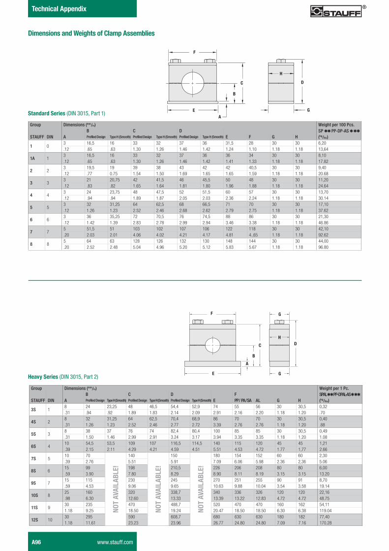
Group Dimensions (mm/in) Weight per 100 Pcs.B C D SP QQ PP-DP-AS Q QQ
STAUFF DIN A Profiled Design Type H (Smooth) Profiled Design Type H (Smooth) Profiled Design Type H (Smooth) E F G H (kg/lbs)
1 03 16,5 16 33 32 37 36 31,5 28 30 30 6,20.12 .65 .63 1.30 1.26 1.46 1.42 1.24 1.10 1.18 1.18 13,64
1A 13 16,5 16 33 32 37 36 36 34 30 30 8,10.12 .65 .63 1.30 1.26 1.46 1.42 1.41 1.33 1.18 1.18 17.82
2 23 19,5 19 39 38 43 42 42 40,5 30 30 9,40.12 .77 0.75 1.54 1.50 1.69 1.65 1.65 1.59 1.18 1.18 20.68
3 33 21 20,75 42 41,5 46 45,5 50 48 30 30 11,20.12 .83 .82 1.65 1.64 1.81 1.80 1.96 1.88 1.18 1.18 24.64
4 43 24 23,75 48 47,5 52 51,5 60 57 30 30 13,70.12 .94 .94 1.89 1.87 2.05 2.03 2.36 2.24 1.18 1.18 30.14
5 53 32 31,25 64 62,5 68 66,5 71 70 30 30 17,10.12 1.26 1.23 2.52 2.46 2.68 2.62 2.79 2.75 1.18 1.18 37.62
6 63 36 35,25 72 70,5 76 74,5 88 86 30 30 21,30.12 1.42 1.39 2.83 2.78 2.99 2.94 3.46 3.38 1.18 1.18 46.86
7 75 51,5 51 103 102 107 106 122 118 30 30 42,10.20 2.03 2.01 4.06 4.02 4.21 4.17 4.81 4.,65 1.18 1.18 92.62
8 85 64 63 128 126 132 130 148 144 30 30 44,00.20 2.52 2.48 5.04 4.96 5.20 5.12 5.83 5.67 1.18 1.18 96.80
Standard Series (DIN 3015, Part 1)
F
C
B
AE
Heavy Series (DIN 3015, Part 2)
F
C
B
A
E
G
DH
G
Group Dimensions (mm/in) Weight per 1 Pc.B C D F SPAL QQ PP-DPAL-AS Q QQ
STAUFF DIN A Profiled Design Type H (Smooth) Profiled Design Type H (Smooth) Profiled Design Type H (Smooth) E PP / PA / SA AL G H (kg/lbs)
3S 18 24 23,25 48 46,5 54,4 52,9 74 55 56 30 30,5 0,32.31 .94 .92 1.89 1.83 2.14 2.09 2.91 2.16 2.20 1.18 1.20 .70
4S 28 32 31,25 64 62,5 70,4 68,9 86 70 70 30 30,5 0,40.31 1.26 1.23 2.52 2.46 2.77 2.72 3.39 2.76 2.76 1.18 1.20 .88
5S 38 38 37 76 74 82,4 80,4 100 85 85 30 30,5 0,49.31 1.50 1.46 2.99 2.91 3.24 3.17 3.94 3.35 3.35 1.18 1.20 1.08
6S 410 54,5 53,5 109 107 116,5 114,5 140 115 120 45 45 1,21.39 2.15 2.11 4.29 4.21 4.59 4.51 5.51 4.53 4.72 1.77 1,77 2.66
7S 510 70
NOT
AVAI
LABL
E!
140
NOT
AVAI
LABL
E!
150
NOT
AVAI
LABL
E!
180 154 152 60 60 2,30.39 2.76 5.51 5.91 7.09 6.06 5.98 2.36 2,36 5.06
8S 615 99 198 210,5 226 206 208 80 80 6,00.59 3.90 7.80 8.29 8.90 8.11 8.19 3.15 3.15 13.20
9S 715 115 230 245 270 251 255 90 91 8,70.59 4.53 9.06 9.65 10.63 9.88 10.04 3.54 3.58 19.14
10S 825 160 320 338,7 340 336 326 120 120 22,16.98 6.30 12.60 13.33 13.39 13.22 12.83 4.72 4.72 48.75
11S 930 235 470 488,7 520 470 470 160 162 54,111.18 9.25 18.50 19.24 20.47 18.50 18.50 6.30 6.38 119.04
12S 1030 295 590 608,7 680 630 630 180 182 77,401.18 11.61 23.23 23.96 26.77 24.80 24.80 7.09 7.16 170.28
D
G
H
Dimensions and Weights of Clamp Assemblies
A96 www.stauff.com
Schelle-2012-03-28-EN.indd 96 29.03.2012 10:13:21
STAU
FF
Clam
psA
Technical Appendix
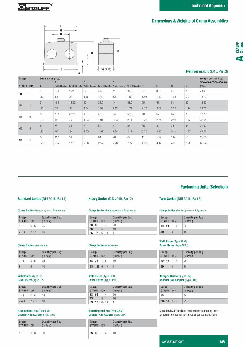
Group Dimensions (mm/in) Weight per 100 Pcs.B C D SP QQ/QQ PP-GD-AS Q QQ
STAUFF DIN A Profiled Design Type H (Smooth) Profiled Design Type H (Smooth) Profiled Design Type H (Smooth) E F G H (kg/lbs)
1D 13 16,5 16,25 37 36,5 41 40,5 37 36 34 20 7,60
.12 .65 .64 1.46 1.44 1.61 1.59 1.46 1.42 1.34 .79 16.72
2D 25 18,5 18,25 39 38,5 44 43,5 55 53 52 29 13,50
.20 .73 .72 1.54 1.52 1.73 1.71 2.17 2.09 2.05 1.14 29.70
3D 35 23,5 23,25 49 48,5 54 53,5 70 67 65 36 17,70
.20 .93 .92 1.93 1.91 2.13 2.11 2.76 2.64 2.56 1.42 38.94
4D 45 25 24 52 50 57 55 85 80 79 45 20,40
.20 .98 .94 2.05 1.97 2.24 2.17 3.35 3.15 3.11 1.77 44.88
5D 55 31,5 31 65 64 70 69 110 106 102 56 27,70
.20 1.24 1.22 2.56 2.52 2.76 2.72 4.33 4.17 4.02 2.20 60.94
F
C
B
AE
GH
D
30 (1.18)Twin Series (DIN 3015, Part 3)
Dimensions & Weights of Clamp Assemblies
Packaging Units (Selection)
Twin Series (DIN 3015, Part 3)Heavy Series (DIN 3015, Part 2)Standard Series (DIN 3015, Part 1)
Group Quantity per BagSTAUFF DIN (in Pcs.)
1 - 6 0 - 6 25
7 + 8 7 + 8 10
Clamp Bodies (Polypropylene / Polyamide)
Weld Plates (Type SP)Cover Plates (Type DP)
Hexagon Rail Nut (Type SM) Channel Rail Adaptor (Type CRA)
Group Quantity per BagSTAUFF DIN (in Pcs.)3S - 6S 1 - 4 207S 5 108S - 12S 6 - 10 1
Clamp Bodies (Aluminium)
Group Quantity per BagSTAUFF DIN (in Pcs.)
1 - 6 0 - 6 25
7 + 8 7 + 8 10
Group Quantity per BagSTAUFF DIN (in Pcs.)
1 - 8 0 - 8 50
Clamp Bodies (Polypropylene / Polyamide)
Group Quantity per BagSTAUFF DIN (in Pcs.)
3S - 7S 1 - 5 10
8S - 12S 6 - 10 1
Weld Plates (Type SPAL) Cover Plates (Type DPAL)
Group Quantity per BagSTAUFF DIN (in Pcs.)3S - 6S 1 - 4 207S 5 108S - 12S 6 - 10 1
Mounting Rail Nut (Type GMV) Channel Rail Adaptor (Type CRA)
Group Quantity per BagSTAUFF DIN (in Pcs.)
3S - 6S 1 - 4 40
Group Quantity per BagSTAUFF DIN (in Pcs.)
1D - 4D 1 - 4 25
5D 5 10
Clamp Bodies (Polypropylene / Polyamide)
Weld Plates (Type SPAL) Cover Plates (Type DPAL)
Hexagon Rail Nut (Type SM) Channel Rail Adaptor (Type CRA)
Group Quantity per BagSTAUFF DIN (in Pcs.)
1 - 5 0 - 5 25
6 6 10
Clamp Bodies (Aluminium)
Group Quantity per BagSTAUFF DIN (in Pcs.)
1D - 4D 1 - 4 25
5D 5 10
Group Quantity per BagSTAUFF DIN (in Pcs.)
1D 1 50
2D - 5D 2 - 5 25
Consult STAUFF and ask for standard packaging units for further components or special packaging options.
www.stauff.com A97
Schelle-2012-03-28-EN.indd 97 29.03.2012 10:13:21

Schelle-2012-03-28-EN.indd 98 29.03.2012 10:13:21