Embed Size (px)
Citation preview
ATTACHMENT A – BO/200200646
TECHNICAL ANALYSIS REPORT
Report No. 20/02
Task File No. BE/200200008
Occurrence File No: BO/200200646
Examination of a Failed Rolls-Royce RB211-524 Turbofan Engine
Boeing Commercial Aircraft Group, 747-436, G-BNLD
1 March 2002
ATTACHMENT 1 – BO/200200646
ii
CONTENTS
1. FACTUAL INFORMATION...................................................................................................1
1.1. History of the flight.........................................................................................................1
1.2. Engine history .................................................................................................................1
1.3. Blade history ...................................................................................................................2
1.4. Blade inspection history..................................................................................................2
1.5. Engine and nacelle damage.............................................................................................3 1.5.1. Fan and rotor assembly..........................................................................................3 1.5.2. Intake cowl ............................................................................................................5 1.5.3. Blade fragment trajectories....................................................................................8 1.5.4. Accessory equipment (fan case) ............................................................................8 1.5.5. Thrust reverser assembly .......................................................................................9 1.5.6. Number-4 engine .................................................................................................10
1.6. Aircraft damage.............................................................................................................10 1.6.1. Number-3 engine pylon .......................................................................................11 1.6.2. Wing, stabiliser and control surfaces...................................................................11 1.6.3. Fuselage ...............................................................................................................12
1.7. Blade failure ..................................................................................................................14 1.7.1. Identification markings........................................................................................14 1.7.2. Fracture surfaces..................................................................................................15 1.7.3. Pre-existing defect ...............................................................................................18 1.7.4. Previous fan blade failures ..................................................................................18
2. ANALYSIS ............................................................................................................................19
2.1. Engine failure ................................................................................................................19
2.2. Blade defect...................................................................................................................19
ATTACHMENT 1 – BO/200200646
1
1. FACTUAL INFORMATION
1.1.
1.2.
History of the flight
On the evening of March 1, 2002, Boeing 747-436 aircraft G-BNLD sustained the failure of the number-3 (right inboard) engine during a scheduled regular passenger transport flight from Sydney to Bangkok. The flight crew experienced vibrations and received an ENG 3 REVERSER engine indicating and crew alerting system (EICAS) message. The crew shut down the number-3 engine and completed checklist items before returning the aircraft to Sydney.
An initial engineering examination found that a fan blade from the number-3 engine had failed and that debris had punctured the engine cowl, the right wing leading and trailing edge flaps and the fuselage; damaging a structural member above the wing root area. The inspection found fractured fasteners and other components beneath the fan cowls and damage to the structure associated with the thrust reverser assembly. Debris from the number-3 engine was also found embedded within the intake cowl of the adjacent number-4 engine.
Engine history
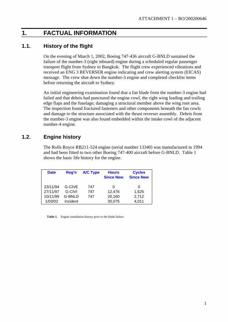
The Rolls Royce RB211-524 engine (serial number 13340) was manufactured in 1994 and had been fitted to two other Boeing 747-400 aircraft before G-BNLD. Table 1 shows the basic life history for the engine.
Date Reg'n A/C Type Hours CyclesSince New Since New
23/11/94 G-CIVE 747 0 027/11/97 G-CIVI 747 12,476 1,52510/11/99 G-BNLD 747 20,160 2,7121/03/02 Incident 30,075 4,011
Table 1. Engine installation history prior to the blade failure.
ATTACHMENT 1 – BO/200200646
2
1.3.
1.4.
01/92 1308
Installed 02/92 G-BNWL 767 1 13426 1308Removed 12/92 3312 A/C HANGAR CHECK
Installed 01/93 G-BNWL 767 1 13426 3312Removed 02/93 3532 2814 15/05/93 SHOP VISIT (HIGH VIBS & TGT)
Installed 06/93 G-BNLS 747 2 13050 3532Removed 14/08/93 4440 2916 SHOP VISIT (FIRE)
Installed 11/93 G-BNWG 767 2 13409 4440Removed 1/09/95 11285 4294 21/10/95 SHOP VISIT (HP Turbine blade failure)
Installed 16/11/95 G-BNWU 767 1 13409 11285Removed 05/97 17926 SHOP VISIT (HP Turbine blade shroud missing)
Installed 29/05/97 G-BNWJ 767 1 13409 17926Removed 08/99 23085 8145 28/10/99 SHOP VISIT (MID-LIFE)
Installed 16/11/99 G-BNLD 747 3 13340 23085Removed 03/02 32000 9444 FAN BLADE FAILURE
Blade history
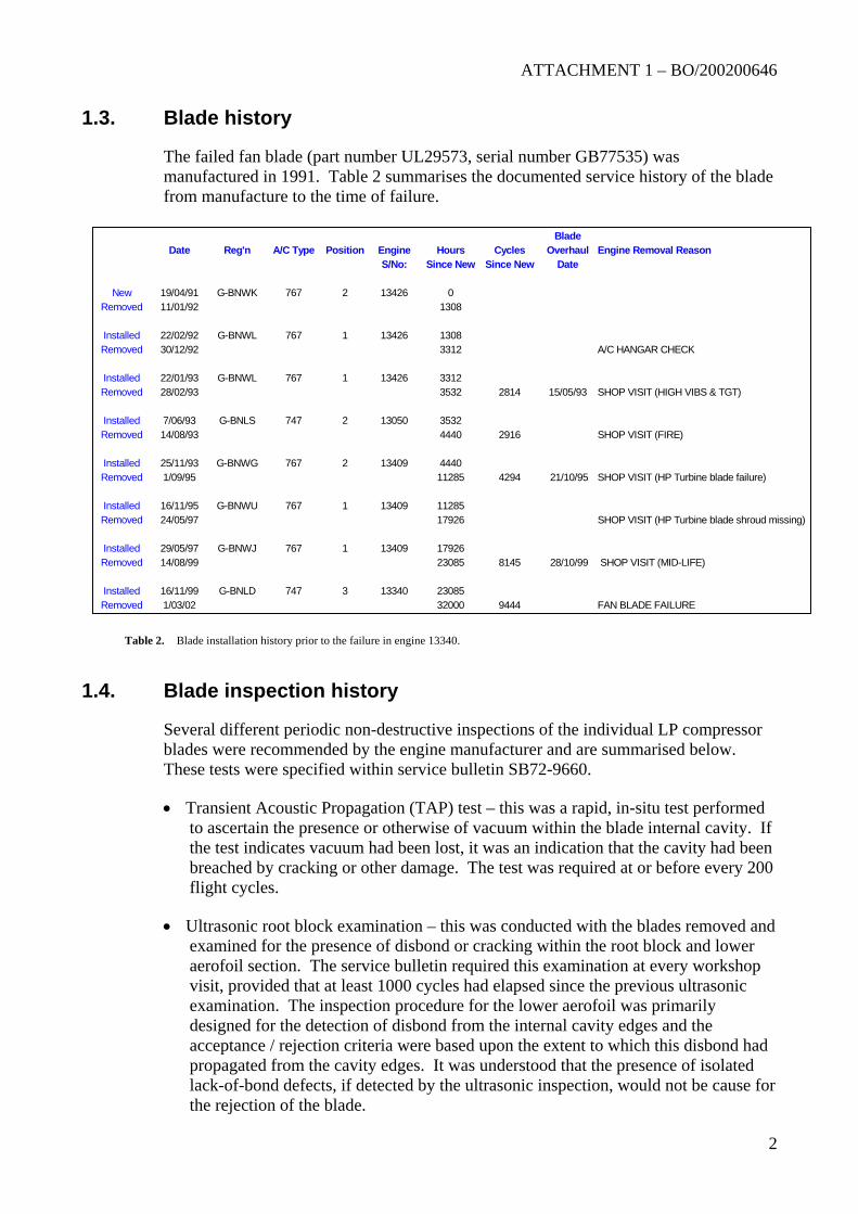
The failed fan blade (part number UL29573, serial number GB77535) was manufactured in 1991. Table 2 summarises the documented service history of the blade from manufacture to the time of failure.
11/
22/30/
22/28/
7/
25/
24/
14/
1/
BladeDate Reg'n A/C Type Position Engine Hours Cycles Overhaul Engine Removal Reason
S/No: Since New Since New Date
New 19/04/91 G-BNWK 767 2 13426 0Removed
Table 2. Blade installation history prior to the failure in engine 13340.
Blade inspection history
Several different periodic non-destructive inspections of the individual LP compressor blades were recommended by the engine manufacturer and are summarised below. These tests were specified within service bulletin SB72-9660.
• Transient Acoustic Propagation (TAP) test – this was a rapid, in-situ test performed to ascertain the presence or otherwise of vacuum within the blade internal cavity. If the test indicates vacuum had been lost, it was an indication that the cavity had been breached by cracking or other damage. The test was required at or before every 200 flight cycles.
• Ultrasonic root block examination – this was conducted with the blades removed and examined for the presence of disbond or cracking within the root block and lower aerofoil section. The service bulletin required this examination at every workshop visit, provided that at least 1000 cycles had elapsed since the previous ultrasonic examination. The inspection procedure for the lower aerofoil was primarily designed for the detection of disbond from the internal cavity edges and the acceptance / rejection criteria were based upon the extent to which this disbond had propagated from the cavity edges. It was understood that the presence of isolated lack-of-bond defects, if detected by the ultrasonic inspection, would not be cause for the rejection of the blade.
ATTACHMENT 1 – BO/200200646
3
1.5.
1.5.1.
• Ultrasonic C-Scan – this was an advanced inspection method for the aerofoil sections. It was required at each workshop visit if the time since the last C-Scan inspection exceeded 1000 cycles. C-Scan inspection for fan blades was introduced from April 1997 after it was recognised that the TAP testing was not providing adequate protection against lower aerofoil cracks.
Records from the engine manufacturer indicated the last TAP test was performed on February 18 2002, ten days before the engine failure. The last ultrasonic root-block inspection was carried out on October 28 2001. The engine fan set had two workshop visits after the introduction of the C-Scan inspection – May 1997 and August - November 1999. Records indicated the blades were inspected using C-scan during the 1999 overhaul.
Engine and nacelle damage
The ATSB carried out a general inspection of the failed engine before it was removed from the aircraft. The engine had sustained damage to the accessory equipment, thrust reverser assembly and fan cowlings, in addition to the extensive disruption evident within the intake cowling.
Fan and rotor assembly
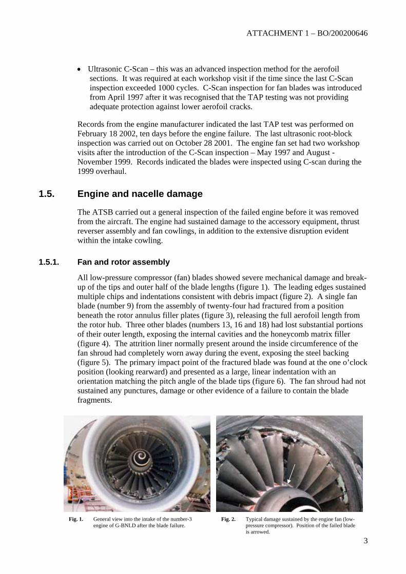
All low-pressure compressor (fan) blades showed severe mechanical damage and break-up of the tips and outer half of the blade lengths (figure 1). The leading edges sustained multiple chips and indentations consistent with debris impact (figure 2). A single fan blade (number 9) from the assembly of twenty-four had fractured from a position beneath the rotor annulus filler plates (figure 3), releasing the full aerofoil length from the rotor hub. Three other blades (numbers 13, 16 and 18) had lost substantial portions of their outer length, exposing the internal cavities and the honeycomb matrix filler (figure 4). The attrition liner normally present around the inside circumference of the fan shroud had completely worn away during the event, exposing the steel backing (figure 5). The primary impact point of the fractured blade was found at the one o’clock position (looking rearward) and presented as a large, linear indentation with an orientation matching the pitch angle of the blade tips (figure 6). The fan shroud had not sustained any punctures, damage or other evidence of a failure to contain the blade fragments.
Fig. 1. General view into the intake of the number-3 engine of G-BNLD after the blade failure.
Fig. 2. Typical damage sustained by the engine fan (low-pressure compressor). Position of the failed blade is arrowed.
ATTACHMENT 1 – BO/200200646
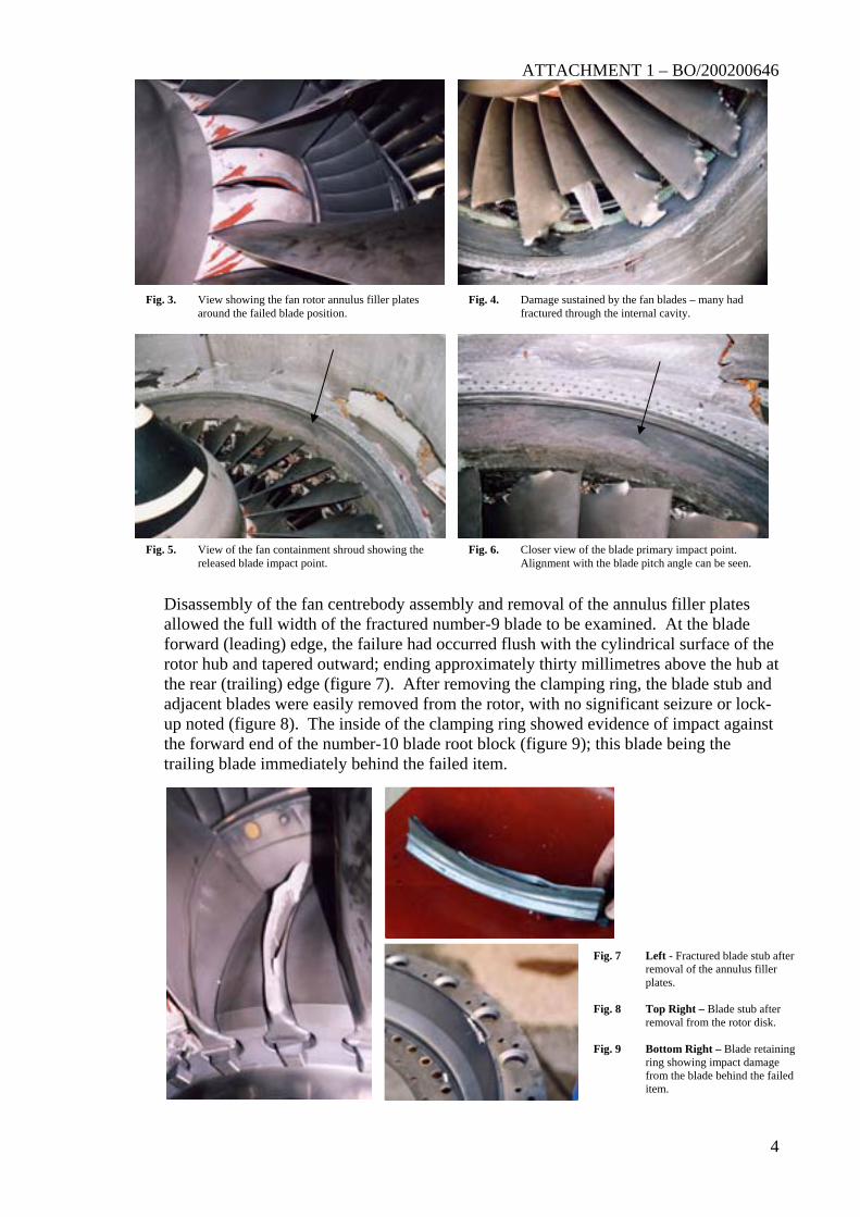
Disassembly of the fan centrebody assembly and removal of the annulus filler plates allowed the full width of the fractured number-9 blade to be examined. At the blade forward (leading) edge, the failure had occurred flush with the cylindrical surface of the rotor hub and tapered outward; ending approximately thirty millimetres above the hub at the rear (trailing) edge (figure 7). After removing the clamping ring, the blade stub and adjacent blades were easily removed from the rotor, with no significant seizure or lock-up noted (figure 8). The inside of the clamping ring showed evidence of impact against the forward end of the number-10 blade root block (figure 9); this blade being the trailing blade immediately behind the failed item.
Fig. 3. View showing the fan rotor annulus filler plates around the failed blade position.
Fig. 4. Damage sustained by the fan blades – many had fractured through the internal cavity.
Fig. 5. View of the fan containment shroud showing the released blade impact point.
Fig. 6. Closer view of the blade primary impact point. Alignment with the blade pitch angle can be seen.
Fig. 7
Fig. 8
Fig. 9
Left - Fractured blade stub after removal of the annulus filler plates.
Top Right – Blade stub after removal from the rotor disk.
Bottom Right – Blade retaining ring showing impact damage from the blade behind the failed item.
4
ATTACHMENT 1 – BO/200200646
1.5.2.
A large amount of debris had accumulated behind the fan, with most lodging against the outlet guide vanes. The debris comprised mostly acoustic lining and remnants of the core inlet fairings. No sections or fragments of the liberated fan blade were found. The core inlet guide vanes showed only minor, random mechanical damage along the leading edges.
Intake cowl
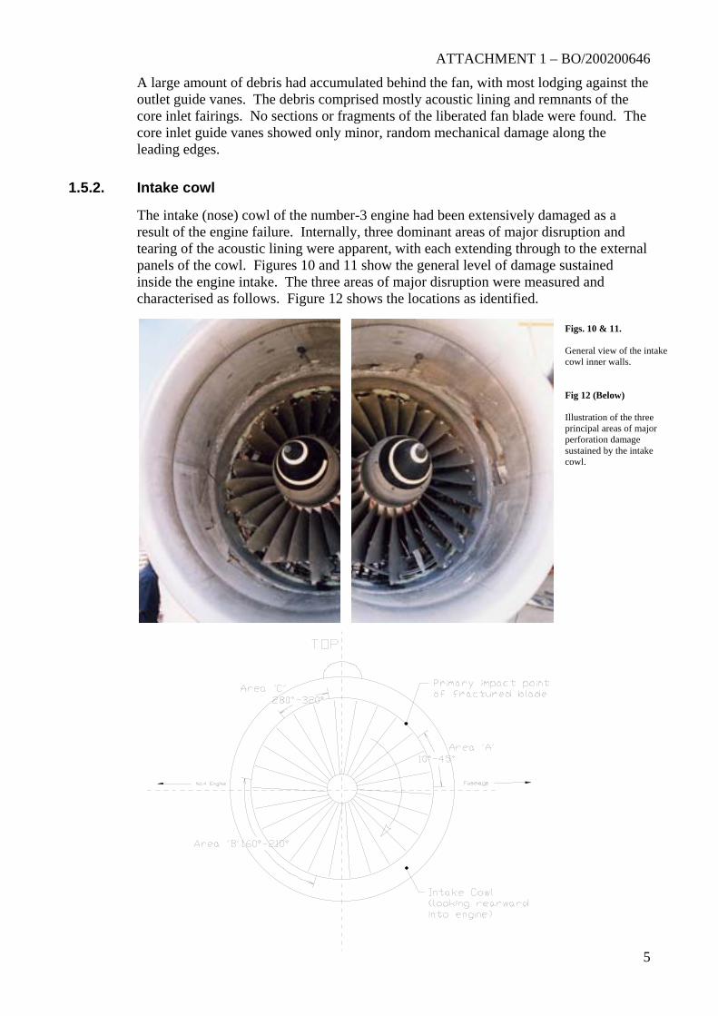
The intake (nose) cowl of the number-3 engine had been extensively damaged as a result of the engine failure. Internally, three dominant areas of major disruption and tearing of the acoustic lining were apparent, with each extending through to the external panels of the cowl. Figures 10 and 11 show the general level of damage sustained inside the engine intake. The three areas of major disruption were measured and characterised as follows. Figure 12 shows the locations as identified.
Figs. 10 & 11. General view of the intake cowl inner walls. Fig 12 (Below) Illustration of the three principal areas of major perforation damage sustained by the intake cowl.
5
ATTACHMENT 1 – BO/200200646
6
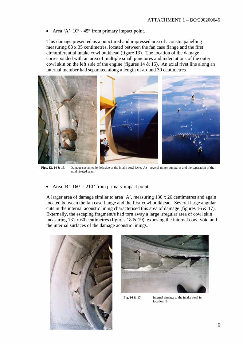
• Area ‘A’ 10° - 45° from primary impact point.
This damage presented as a punctured and impressed area of acoustic panelling measuring 88 x 35 centimetres, located between the fan case flange and the first circumferential intake cowl bulkhead (figure 13). The location of the damage corresponded with an area of multiple small punctures and indentations of the outer cowl skin on the left side of the engine (figures 14 & 15). An axial rivet line along an internal member had separated along a length of around 30 centimetres.
Figs. 13, 14 & 15. Damage sustained by left side of the intake cowl (Area A) – several minor punctures and the separation of the axial riveted seam.
• Area ‘B’ 160° - 210° from primary impact point.
A larger area of damage similar to area ‘A’, measuring 130 x 26 centimetres and again located between the fan case flange and the first cowl bulkhead. Several large angular cuts in the internal acoustic lining characterised this area of damage (figures 16 & 17). Externally, the escaping fragment/s had torn away a large irregular area of cowl skin measuring 131 x 60 centimetres (figures 18 & 19), exposing the internal cowl void and the internal surfaces of the damage acoustic linings.
Fig. 16 & 17. Internal damage to the intake cowl in location ‘B’.
ATTACHMENT 1 – BO/200200646
7
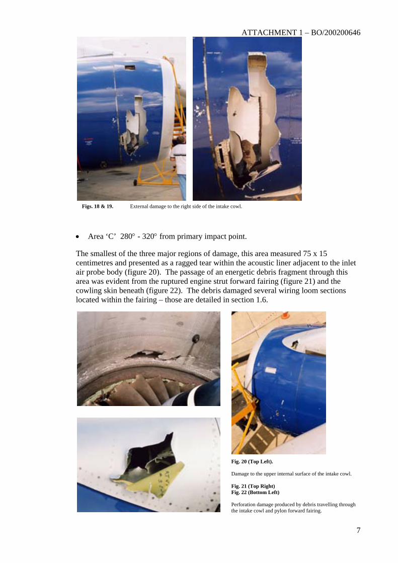
Figs. 18 & 19. External damage to the right side of the intake cowl.
• Area ‘C’ 280° - 320° from primary impact point.
The smallest of the three major regions of damage, this area measured 75 x 15 centimetres and presented as a ragged tear within the acoustic liner adjacent to the inlet air probe body (figure 20). The passage of an energetic debris fragment through this area was evident from the ruptured engine strut forward fairing (figure 21) and the cowling skin beneath (figure 22). The debris damaged several wiring loom sections located within the fairing – those are detailed in section 1.6.
Fig. 20 (Top Left). Damage to the upper internal surface of the intake cowl. Fig. 21 (Top Right) Fig. 22 (Bottom Left) Perforation damage produced by debris travelling through the intake cowl and pylon forward fairing.
ATTACHMENT 1 – BO/200200646
8
1.5.3.
1.5.4.
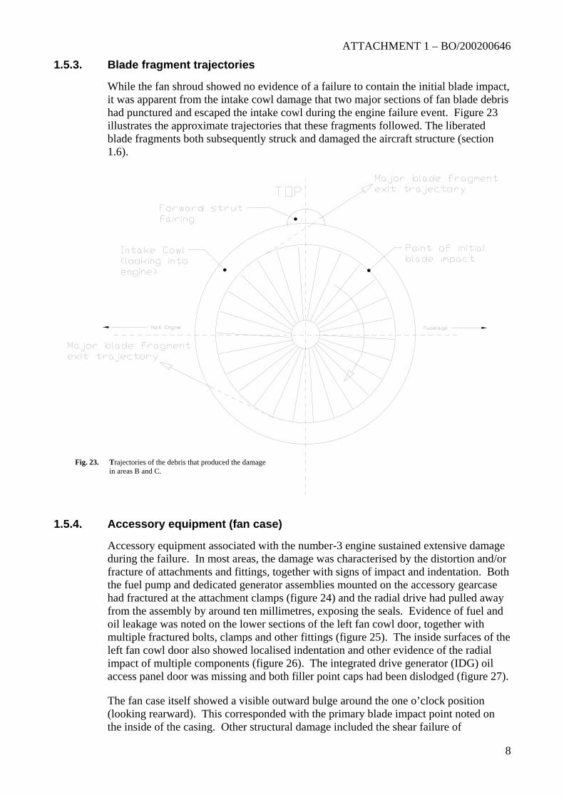
Blade fragment trajectories
While the fan shroud showed no evidence of a failure to contain the initial blade impact, it was apparent from the intake cowl damage that two major sections of fan blade debris had punctured and escaped the intake cowl during the engine failure event. Figure 23 illustrates the approximate trajectories that these fragments followed. The liberated blade fragments both subsequently struck and damaged the aircraft structure (section 1.6).
Fig. 23. Trajectories of the debris that produced the damage in areas B and C.
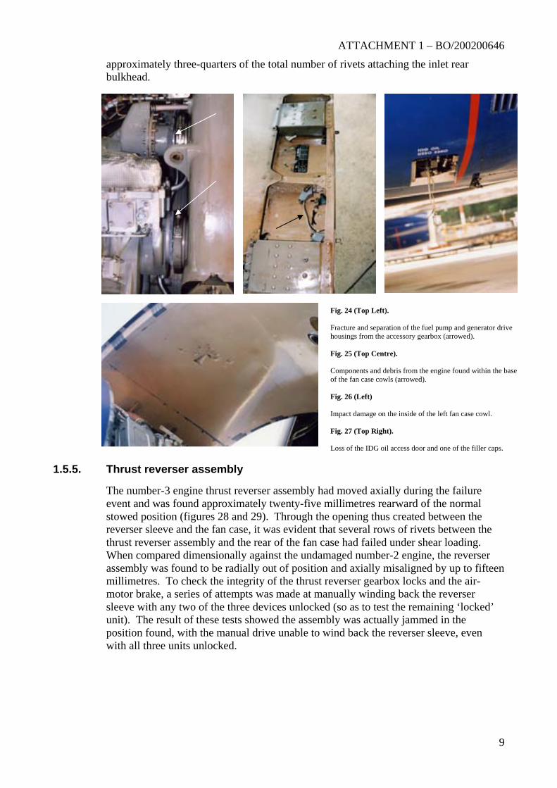
Accessory equipment (fan case)
Accessory equipment associated with the number-3 engine sustained extensive damage during the failure. In most areas, the damage was characterised by the distortion and/or fracture of attachments and fittings, together with signs of impact and indentation. Both the fuel pump and dedicated generator assemblies mounted on the accessory gearcase had fractured at the attachment clamps (figure 24) and the radial drive had pulled away from the assembly by around ten millimetres, exposing the seals. Evidence of fuel and oil leakage was noted on the lower sections of the left fan cowl door, together with multiple fractured bolts, clamps and other fittings (figure 25). The inside surfaces of the left fan cowl door also showed localised indentation and other evidence of the radial impact of multiple components (figure 26). The integrated drive generator (IDG) oil access panel door was missing and both filler point caps had been dislodged (figure 27).
The fan case itself showed a visible outward bulge around the one o’clock position (looking rearward). This corresponded with the primary blade impact point noted on the inside of the casing. Other structural damage included the shear failure of
ATTACHMENT 1 – BO/200200646
1.5.5.
approximately three-quarters of the total number of rivets attaching the inlet rear bulkhead.
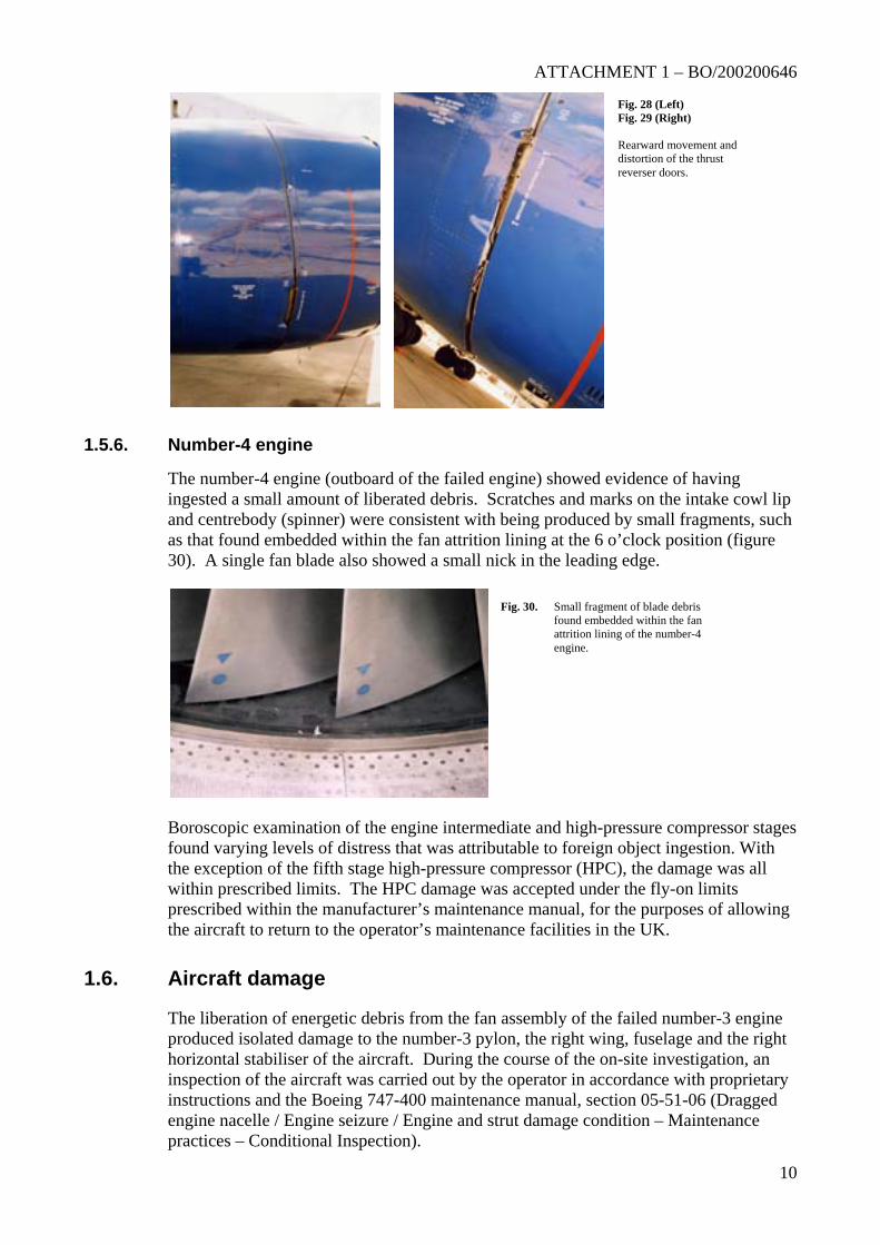
Thrust reverser assembly
The number-3 engine thrust reverser assembly haevent and was found approximately twenty-five mstowed position (figures 28 and 29). Through threverser sleeve and the fan case, it was evident ththrust reverser assembly and the rear of the fan cWhen compared dimensionally against the undamassembly was found to be radially out of positionmillimetres. To check the integrity of the thrust motor brake, a series of attempts was made at masleeve with any two of the three devices unlockeunit). The result of these tests showed the assemposition found, with the manual drive unable to wwith all three units unlocked.
Fig. 24 (Top Left). Fracture and separation of the fuel pump and generator drive housings from the accessory gearbox (arrowed). Fig. 25 (Top Centre). Components and debris from the engine found within the baseof the fan case cowls (arrowed). Fig. 26 (Left) Impact damage on the inside of the left fan case cowl. Fig. 27 (Top Right). Loss of the IDG oil access door and one of the filler caps.
9
d moved axially during the failure illimetres rearward of the normal
e opening thus created between the at several rows of rivets between the ase had failed under shear loading.
aged number-2 engine, the reverser and axially misaligned by up to fifteen
reverser gearbox locks and the air-nually winding back the reverser
d (so as to test the remaining ‘locked’ bly was actually jammed in the ind back the reverser sleeve, even
ATTACHMENT 1 – BO/200200646
10
1.5.6.
1.6.
Fig. 28 (Left) Fig. 29 (Right) Rearward movement and distortion of the thrust reverser doors.
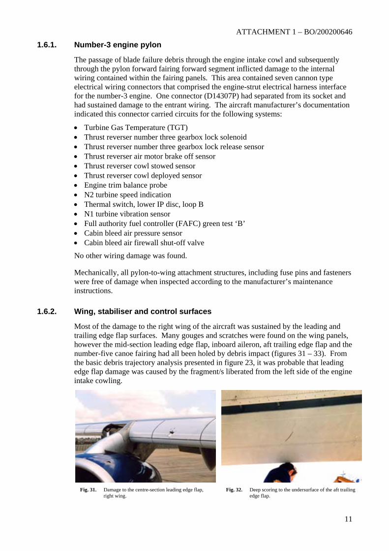
Number-4 engine
The number-4 engine (outboard of the failed engine) showed evidence of having ingested a small amount of liberated debris. Scratches and marks on the intake cowl lip and centrebody (spinner) were consistent with being produced by small fragments, such as that found embedded within the fan attrition lining at the 6 o’clock position (figure 30). A single fan blade also showed a small nick in the leading edge.
Boroscopic examination of the engine intermediate and high-pressure compressor stages found varying levels of distress that was attributable to foreign object ingestion. With the exception of the fifth stage high-pressure compressor (HPC), the damage was all within prescribed limits. The HPC damage was accepted under the fly-on limits prescribed within the manufacturer’s maintenance manual, for the purposes of allowing the aircraft to return to the operator’s maintenance facilities in the UK.
Fig. 30. Small fragment of blade debris found embedded within the fan attrition lining of the number-4 engine.
Aircraft damage
The liberation of energetic debris from the fan assembly of the failed number-3 engine produced isolated damage to the number-3 pylon, the right wing, fuselage and the right horizontal stabiliser of the aircraft. During the course of the on-site investigation, an inspection of the aircraft was carried out by the operator in accordance with proprietary instructions and the Boeing 747-400 maintenance manual, section 05-51-06 (Dragged engine nacelle / Engine seizure / Engine and strut damage condition – Maintenance practices – Conditional Inspection).
ATTACHMENT 1 – BO/200200646
11
1.6.1.
1.6.2.
Number-3 engine pylon
The passage of blade failure debris through the engine intake cowl and subsequently through the pylon forward fairing forward segment inflicted damage to the internal wiring contained within the fairing panels. This area contained seven cannon type electrical wiring connectors that comprised the engine-strut electrical harness interface for the number-3 engine. One connector (D14307P) had separated from its socket and had sustained damage to the entrant wiring. The aircraft manufacturer’s documentation indicated this connector carried circuits for the following systems:
• Turbine Gas Temperature (TGT) • Thrust reverser number three gearbox lock solenoid • Thrust reverser number three gearbox lock release sensor • Thrust reverser air motor brake off sensor • Thrust reverser cowl stowed sensor • Thrust reverser cowl deployed sensor • Engine trim balance probe • N2 turbine speed indication • Thermal switch, lower IP disc, loop B • N1 turbine vibration sensor • Full authority fuel controller (FAFC) green test ‘B’ • Cabin bleed air pressure sensor • Cabin bleed air firewall shut-off valve
No other wiring damage was found.
Mechanically, all pylon-to-wing attachment structures, including fuse pins and fasteners were free of damage when inspected according to the manufacturer’s maintenance instructions.
Wing, stabiliser and control surfaces
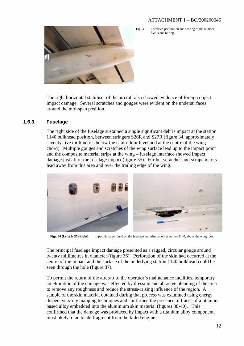
Most of the damage to the right wing of the aircraft was sustained by the leading and trailing edge flap surfaces. Many gouges and scratches were found on the wing panels, however the mid-section leading edge flap, inboard aileron, aft trailing edge flap and the number-five canoe fairing had all been holed by debris impact (figures 31 – 33). From the basic debris trajectory analysis presented in figure 23, it was probable that leading edge flap damage was caused by the fragment/s liberated from the left side of the engine intake cowling.
Fig. 31. Damage to the centre-section leading edge flap,
right wing. Fig. 32. Deep scoring to the undersurface of the aft trailing
edge flap.
ATTACHMENT 1 – BO/200200646
12
1.6.3. Fuselage
The right horizontal stabiliser of the aircraft also showed evidence of foreign object impact damage. Several scratches and gouges were evident on the undersurfaces around the mid-span position.
Fig. 33. Localised perforation and scoring of the number-five canoe fairing.
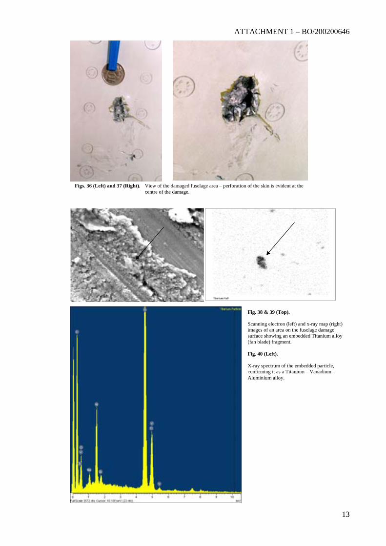
The right side of the fuselage sustained a single significant debris impact at the station 1140 bulkhead position, between stringers S26R and S27R (figure 34, approximately seventy-five millimetres below the cabin floor level and at the centre of the wing chord). Multiple gouges and scratches of the wing surface lead up to the impact point and the composite material strips at the wing – fuselage interface showed impact damage just aft of the fuselage impact (figure 35). Further scratches and scrape marks lead away from this area and over the trailing edge of the wing.
The principal fuselage impact damage presented as a ragged, circular gouge around twenty millimetres in diameter (figure 36). Perforation of the skin had occurred at the centre of the impact and the surface of the underlying station 1140 bulkhead could be seen through the hole (figure 37).
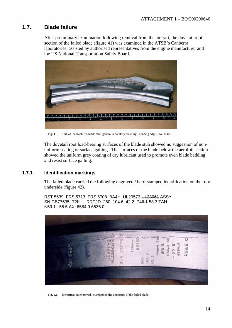
To permit the return of the aircraft to the operator’s maintenance facilities, temporary amelioration of the damage was effected by dressing and abrasive blending of the area to remove any roughness and reduce the stress-raising influence of the region. A sample of the skin material obtained during that process was examined using energy dispersive x-ray mapping techniques and confirmed the presence of traces of a titanium based alloy embedded into the aluminium skin material (figures 38-40). This confirmed that the damage was produced by impact with a titanium alloy component, most likely a fan blade fragment from the failed engine.
Figs. 34 (Left) & 35 (Right). Impact damage found on the fuselage and trim panels at station 1140, above the wing root.
ATTACHMENT 1 – BO/200200646
13
Figs. 36 (Left) and 37 (Right). View of the damaged fuselage area – perforation of the skin is evident at the centre of the damage.
Fig. 38 & 39 (Top). Scanning electron (left) and x-ray map (right) images of an area on the fuselage damage surface showing an embedded Titanium alloy (fan blade) fragment. Fig. 40 (Left). X-ray spectrum of the embedded particle, confirming it as a Titanium – Vanadium – Aluminium alloy.
ATTACHMENT 1 – BO/200200646
14
1.7.
1.7.1.
Blade failure
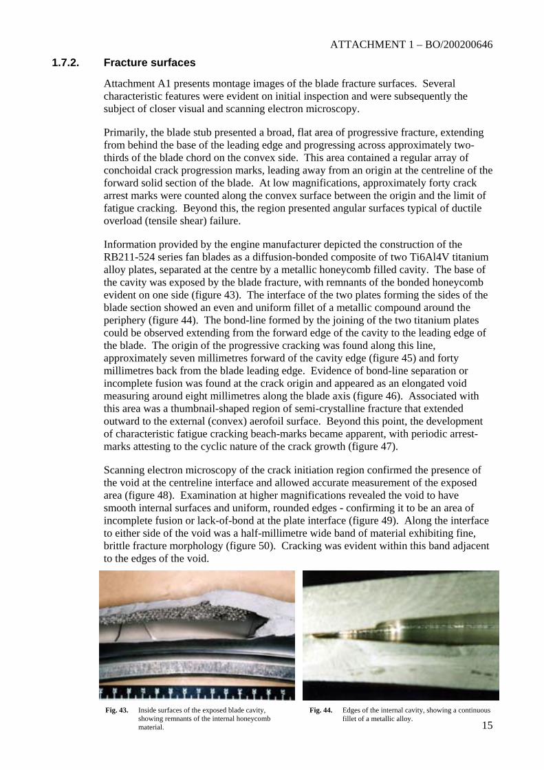
After preliminary examination following removal from the aircraft, the dovetail root section of the failed blade (figure 41) was examined in the ATSB’s Canberra laboratories, assisted by authorised representatives from the engine manufacturer and the US National Transportation Safety Board.
The dovetail root load-bearing surfaces of the blade stub showed no suggestion of non-uniform seating or surface galling. The surfaces of the blade below the aerofoil section showed the uniform grey coating of dry lubricant used to promote even blade bedding and resist surface galling.
Fig. 41. Stub of the fractured blade after general laboratory cleaning. Leading edge is to the left.
Identification markings
The failed blade carried the following engraved / hard-stamped identification on the root underside (figure 42).
RST 5639 FRS 5713 FRS 5708 BA4H UL29573 UL23061 ASSY SN GB77535 T2K--- RRT2D 260 104.6 42.2 P46.1 58.3 TAN N59.1 –55.5 AX 6584.9 6535.0
Fig. 42. Identification engraved / stamped on the underside of the failed blade.
ATTACHMENT 1 – BO/200200646
15
1.7.2. Fracture surfaces
Attachment A1 presents montage images of the blade fracture surfaces. Several characteristic features were evident on initial inspection and were subsequently the subject of closer visual and scanning electron microscopy.
Primarily, the blade stub presented a broad, flat area of progressive fracture, extending from behind the base of the leading edge and progressing across approximately two-thirds of the blade chord on the convex side. This area contained a regular array of conchoidal crack progression marks, leading away from an origin at the centreline of the forward solid section of the blade. At low magnifications, approximately forty crack arrest marks were counted along the convex surface between the origin and the limit of fatigue cracking. Beyond this, the region presented angular surfaces typical of ductile overload (tensile shear) failure.
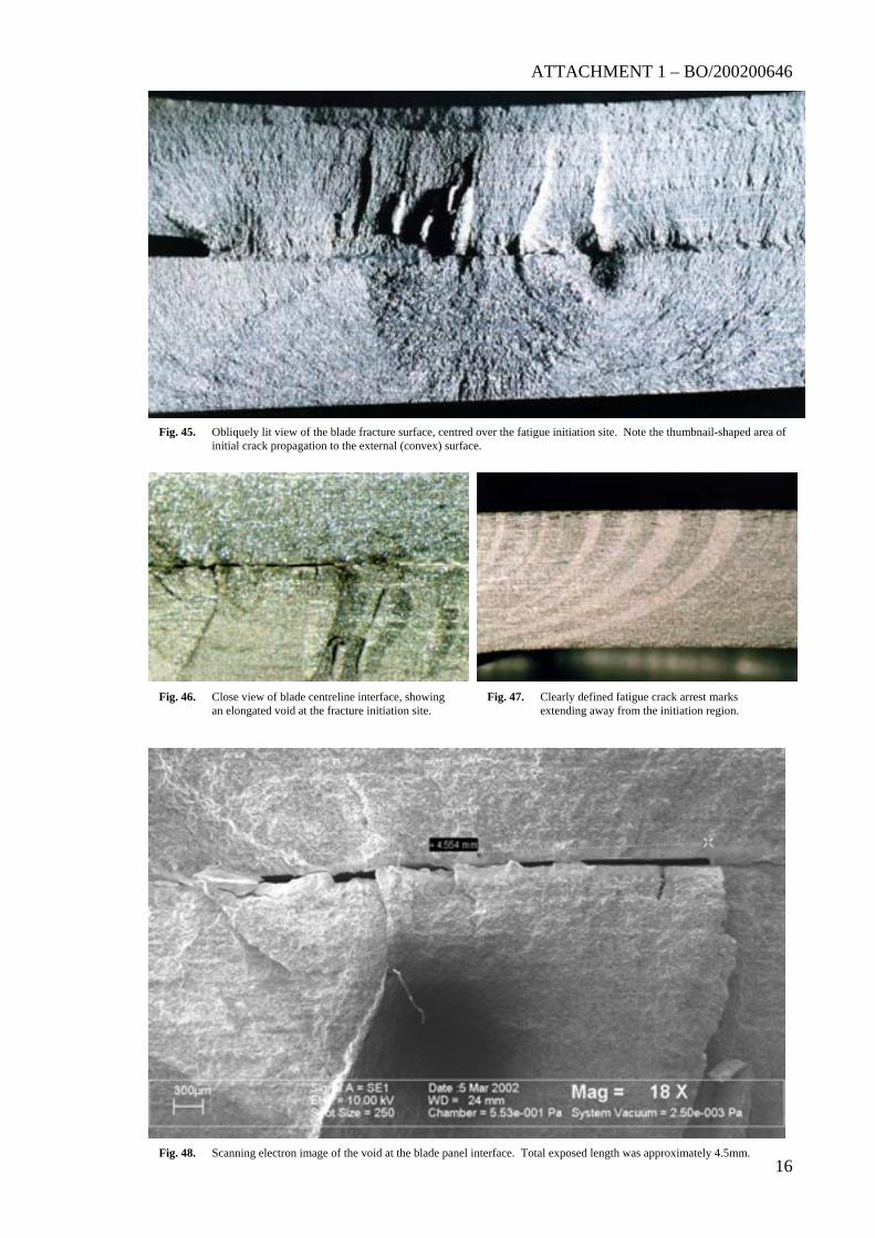
Information provided by the engine manufacturer depicted the construction of the RB211-524 series fan blades as a diffusion-bonded composite of two Ti6Al4V titanium alloy plates, separated at the centre by a metallic honeycomb filled cavity. The base of the cavity was exposed by the blade fracture, with remnants of the bonded honeycomb evident on one side (figure 43). The interface of the two plates forming the sides of the blade section showed an even and uniform fillet of a metallic compound around the periphery (figure 44). The bond-line formed by the joining of the two titanium plates could be observed extending from the forward edge of the cavity to the leading edge of the blade. The origin of the progressive cracking was found along this line, approximately seven millimetres forward of the cavity edge (figure 45) and forty millimetres back from the blade leading edge. Evidence of bond-line separation or incomplete fusion was found at the crack origin and appeared as an elongated void measuring around eight millimetres along the blade axis (figure 46). Associated with this area was a thumbnail-shaped region of semi-crystalline fracture that extended outward to the external (convex) aerofoil surface. Beyond this point, the development of characteristic fatigue cracking beach-marks became apparent, with periodic arrest-marks attesting to the cyclic nature of the crack growth (figure 47).
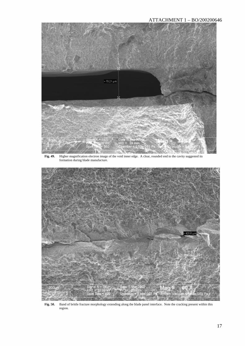
Scanning electron microscopy of the crack initiation region confirmed the presence of the void at the centreline interface and allowed accurate measurement of the exposed area (figure 48). Examination at higher magnifications revealed the void to have smooth internal surfaces and uniform, rounded edges - confirming it to be an area of incomplete fusion or lack-of-bond at the plate interface (figure 49). Along the interface to either side of the void was a half-millimetre wide band of material exhibiting fine, brittle fracture morphology (figure 50). Cracking was evident within this band adjacent to the edges of the void.
Fig. 43. Inside surfaces of the exposed blade cavity,
showing remnants of the internal honeycomb material.
Fig. 44. Edges of the internal cavity, showing a continuous fillet of a metallic alloy.
ATTACHMENT 1 – BO/200200646
16
Fig. 45. Obliquely lit view of the blade fracture surface, centred over the fatigue initiation site. Note the thumbnail-shaped area of initial crack propagation to the external (convex) surface.
Fig. 46. Close view of blade centreline interface, showing an elongated void at the fracture initiation site.
Fig. 47. Clearly defined fatigue crack arrest marks extending away from the initiation region.
Fig. 48. Scanning electron image of the void at the blade panel interface. Total exposed length was approximately 4.5mm.
ATTACHMENT 1 – BO/200200646
17
Fig. 49. Higher magnification electron image of the void inner edge. A clear, rounded end to the cavity suggested its formation during blade manufacture.
Fig. 50. Band of brittle fracture morphology extending along the blade panel interface. Note the cracking present within this region.
ATTACHMENT 1 – BO/200200646
18
1.7.3.
1.7.4.
Pre-existing defect
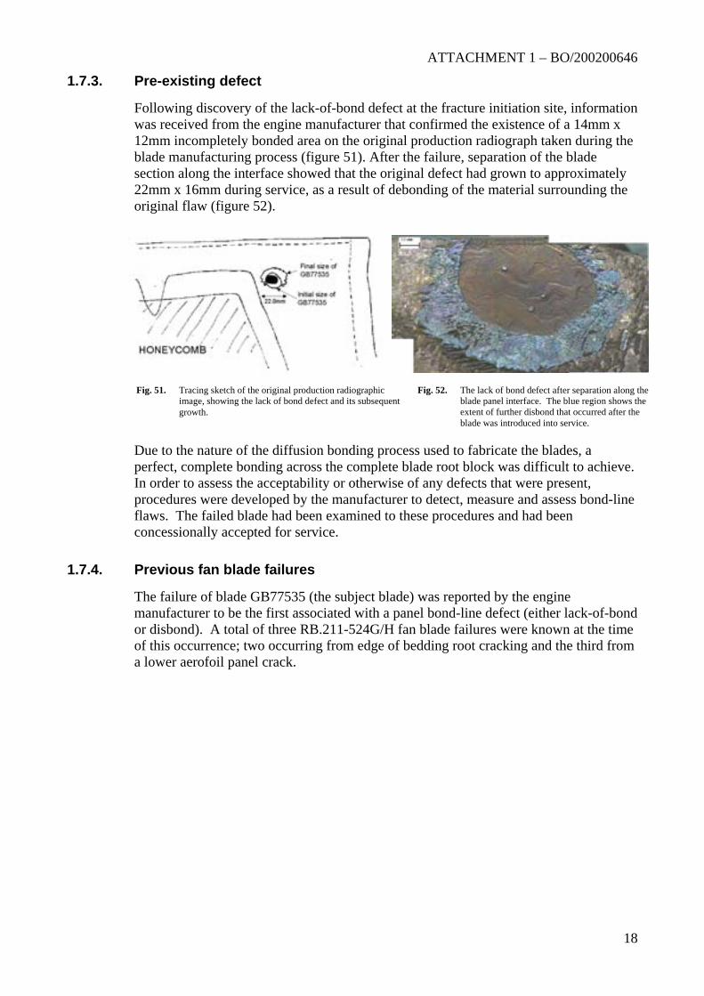
Following discovery of the lack-of-bond defect at the fracture initiation site, information was received from the engine manufacturer that confirmed the existence of a 14mm x 12mm incompletely bonded area on the original production radiograph taken during the blade manufacturing process (figure 51). After the failure, separation of the blade section along the interface showed that the original defect had grown to approximately 22mm x 16mm during service, as a result of debonding of the material surrounding the original flaw (figure 52).
Due to the nature of the diffusion bonding process used to fabricate the blades, a perfect, complete bonding across the complete blade root block was difficult to achieve. In order to assess the acceptability or otherwise of any defects that were present, procedures were developed by the manufacturer to detect, measure and assess bond-line flaws. The failed blade had been examined to these procedures and had been concessionally accepted for service.
Fig. 51. Tracing sketch of the original production radiographic image, showing the lack of bond defect and its subsequent growth.
Fig. 52. The lack of bond defect after separation along the blade panel interface. The blue region shows the extent of further disbond that occurred after the blade was introduced into service.
Previous fan blade failures
The failure of blade GB77535 (the subject blade) was reported by the engine manufacturer to be the first associated with a panel bond-line defect (either lack-of-bond or disbond). A total of three RB.211-524G/H fan blade failures were known at the time of this occurrence; two occurring from edge of bedding root cracking and the third from a lower aerofoil panel crack.
ATTACHMENT 1 – BO/200200646
19
2. ANALYSIS
2.1.
2.2.
Engine failure
Failure of the number-3 engine from G-BNLD occurred as a direct result of the fracture and liberation of a single low-pressure compressor (fan) blade. Fatigue cracking had initiated within the lower aerofoil section of the blade, from the top of a pre-existing internal defect. Located approximately forty millimetres back from the leading edge and thirteen millimetres above the blade root transition, the defect was characterised as an original manufacturing flaw. Growth of fatigue cracking from the defect had progressed transversely outward to intersect the convex aerofoil surface, before propagating with a chordwise orientation under the influence of centrifugal and vibratory operational loads. Final fracture of the blade aerofoil section occurred with fatigue crack growth through approximately one-half of the total blade cross-section.
The liberation of the full length of the blade aerofoil resulted in severe damage to the intake cowl, engine accessory components and the thrust-reverser assembly. The fan case had successfully contained the initial impact with the released blade, however evidence suggested that the liberated section had subsequently broken into several pieces and spiralled forward, before moving back into the rotating blade set to produce extensive secondary damage and the generation of further energetic debris. Three of the largest fragments of fan blade had punctured and exited the engine intake cowl, producing isolated damage to the right wing and the right side of the aircraft fuselage.
Blade defect
The blade defect identified during the engine failure analysis was characterised as an isolated region of incomplete bond between the two plates making up the basic blade structure. From the results of non-destructive inspection performed during blade construction, the engine manufacturer had been aware of the location and size of the defect and had allowed the blade to be put into service on the basis of concessional acceptance criteria.
Once entering service, the engine fan blades were subject to periodic non-destructive inspection procedures designed to detect the development of defects known to be injurious to the blade service life. As the incidence of fatigue cracking from an area of incomplete panel bonding was unknown until the event in question, the inspection procedures were not optimised for the detection of such cracking. As a result, routine non-destructive inspection of the blade during its service life had failed to identify the growth of fatigue cracking from the original flaw.
ATTACHMENT 1 – Technical Analysis Report No. 20/02
1. Attachments
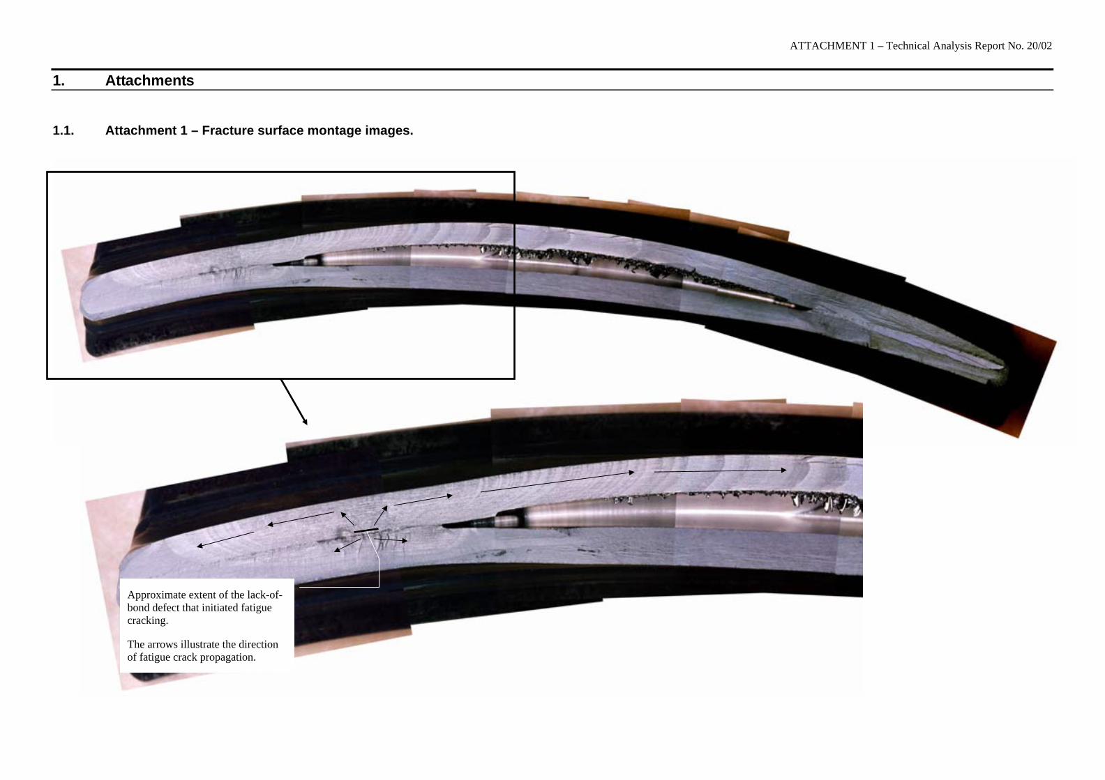
1.1. Attachment 1 – Fracture surface montage images.
Approximate extent of the lack-of-bond defect that initiated fatigue cracking.
The arrows illustrate the direction of fatigue crack propagation.


![CONTENTS · D8568 Pres CPR Class 17 - Clayton Type 1 'Bo-Bo' Class 15 - British Thomson-Houston Type 1 'Bo-Bo' D8233 [968001] Pres ELR Class 20/0 - English Electric Type 1 'Bo-Bo](https://img.pdfslide.us/doc/110x75/60b354169d5fc910fc2ec584/d8568-pres-cpr-class-17-clayton-type-1-bo-bo-class-15-british-thomson-houston.jpg)