Embed Size (px)
Citation preview
For more information: Toll Free 800.475.2077 Tel 949.238.8900 www.sideplate.com
Page 1 of 17
Tech Tips
09/30/2017
SidePlate Connections FAQ
For more information: Toll Free 800.475.2077 Tel 949.238.8900 www.sideplate.com
Page 2 of 17
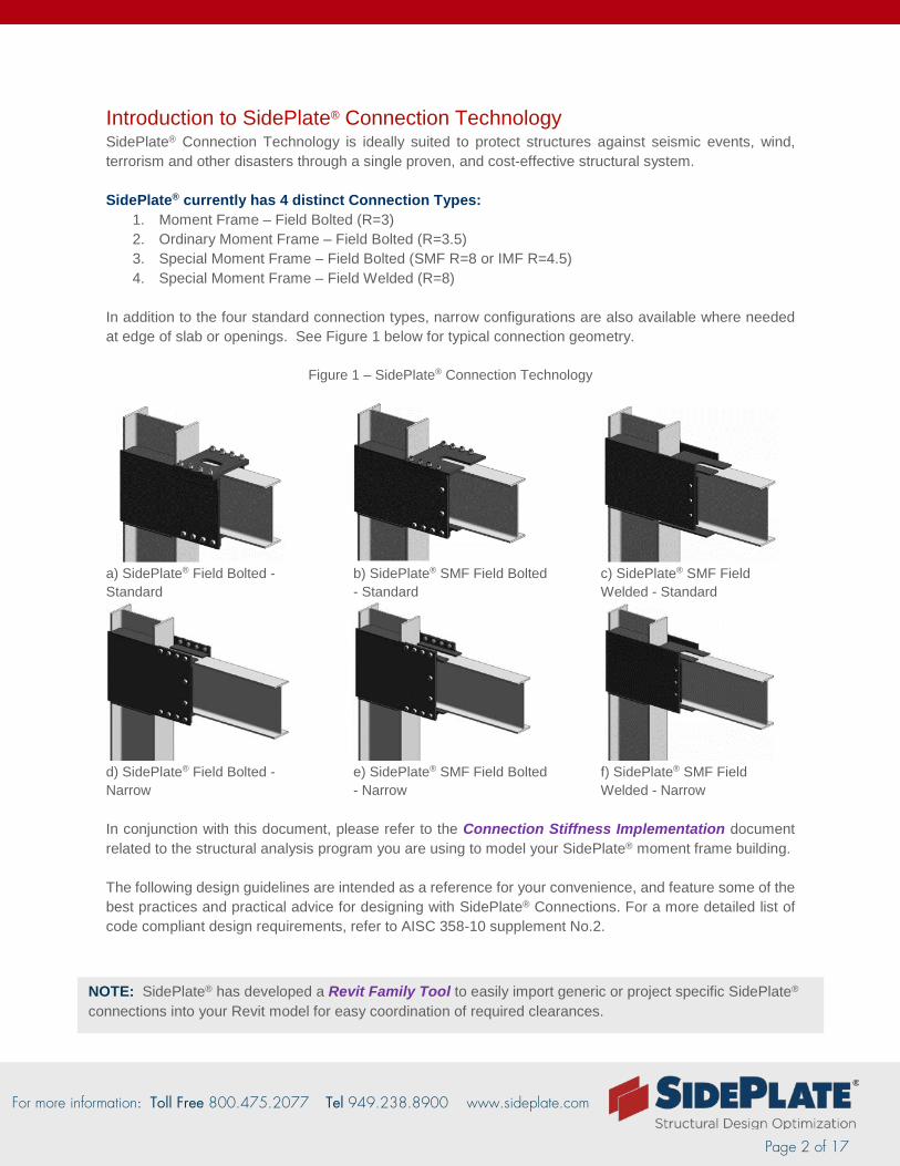
Introduction to SidePlate® Connection Technology SidePlate® Connection Technology is ideally suited to protect structures against seismic events, wind, terrorism and other disasters through a single proven, and cost-effective structural system. SidePlate® currently has 4 distinct Connection Types:
1. Moment Frame – Field Bolted (R=3) 2. Ordinary Moment Frame – Field Bolted (R=3.5) 3. Special Moment Frame – Field Bolted (SMF R=8 or IMF R=4.5) 4. Special Moment Frame – Field Welded (R=8)
In addition to the four standard connection types, narrow configurations are also available where needed at edge of slab or openings. See Figure 1 below for typical connection geometry.
Figure 1 – SidePlate® Connection Technology
a) SidePlate® Field Bolted - Standard
d) SidePlate® Field Bolted - Narrow
b) SidePlate® SMF Field Bolted - Standard
e) SidePlate® SMF Field Bolted - Narrow
c) SidePlate® SMF Field Welded - Standard
f) SidePlate® SMF Field Welded - Narrow
In conjunction with this document, please refer to the Connection Stiffness Implementation document related to the structural analysis program you are using to model your SidePlate® moment frame building. The following design guidelines are intended as a reference for your convenience, and feature some of the best practices and practical advice for designing with SidePlate® Connections. For a more detailed list of code compliant design requirements, refer to AISC 358-10 supplement No.2.
NOTE: SidePlate® has developed a Revit Family Tool to easily import generic or project specific SidePlate® connections into your Revit model for easy coordination of required clearances.
For more information: Toll Free 800.475.2077 Tel 949.238.8900 www.sideplate.com
Page 3 of 17
Architectural Considerations and Schematic Design
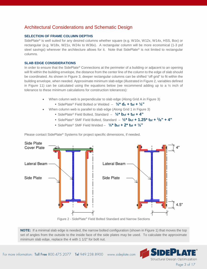
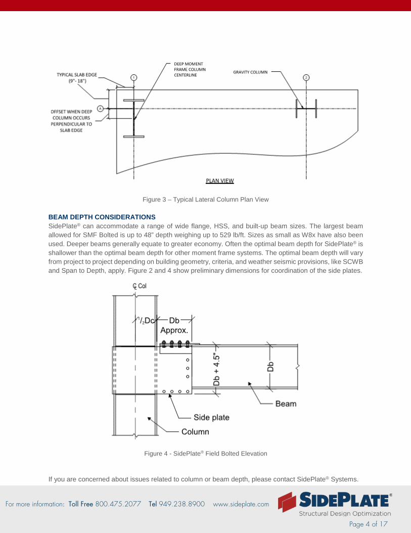
SELECTION OF FRAME COLUMN DEPTHS SidePlate® is well suited for any desired columns whether square (e.g. W10x, W12x, W14x, HSS, Box) or rectangular (e.g. W18x, W21x, W24x to W36x). A rectangular column will be more economical (1-3 psf steel savings) wherever the architecture allows for it. Note that SidePlate® is not limited to rectangular columns. SLAB EDGE CONSIDERATIONS In order to ensure that the SidePlate® Connections at the perimeter of a building or adjacent to an opening will fit within the building envelope, the distance from the center line of the column to the edge of slab should be coordinated. As shown in Figure 3, deeper rectangular columns can be shifted “off grid” to fit within the building envelope, when needed. Approximate minimum slab edge (illustrated in Figure 2, variables defined in Figure 11) can be calculated using the equations below (we recommend adding up to a ½ inch of tolerance to these minimum calculations for construction tolerances):
• When column web is perpendicular to slab edge (Along Grid A in Figure 3) SidePlate® Field Bolted or Welded – ½* dc + tbf + ½”
• When column web is parallel to slab edge (Along Grid 1 in Figure 3) SidePlate® Field Bolted, Standard – ½* bcf + tbf + 4” SidePlate® SMF Field Bolted, Standard – ½* bcf + 1.25* tbf + 1/8” + 4” SidePlate® SMF Field Welded – ½* bcf + 2* tbf + ½”
Please contact SidePlate® Systems for project specific dimensions, if needed.
Figure 2 - SidePlate® Field Bolted Standard and Narrow Sections
NOTE: If a minimal slab edge is needed, the narrow bolted configuration (shown in Figure 1) that moves the top set of angles from the outside to the inside face of the side plates may be used. To calculate the approximate minimum slab edge, replace the 4 with 1 1/2” for bolt nut.
For more information: Toll Free 800.475.2077 Tel 949.238.8900 www.sideplate.com
Page 4 of 17
Figure 3 – Typical Lateral Column Plan View BEAM DEPTH CONSIDERATIONS SidePlate® can accommodate a range of wide flange, HSS, and built-up beam sizes. The largest beam allowed for SMF Bolted is up to 48” depth weighing up to 529 lb/ft. Sizes as small as W8x have also been used. Deeper beams generally equate to greater economy. Often the optimal beam depth for SidePlate® is shallower than the optimal beam depth for other moment frame systems. The optimal beam depth will vary from project to project depending on building geometry, criteria, and weather seismic provisions, like SCWB and Span to Depth, apply. Figure 2 and 4 show preliminary dimensions for coordination of the side plates.
Figure 4 - SidePlate® Field Bolted Elevation
If you are concerned about issues related to column or beam depth, please contact SidePlate® Systems.
For more information: Toll Free 800.475.2077 Tel 949.238.8900 www.sideplate.com
Page 5 of 17
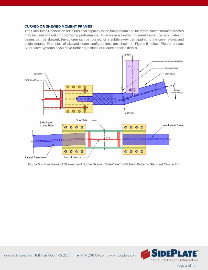
CURVED OR SKEWED MOMENT FRAMES The SidePlate® Connection adds torsional capacity to the frame beam and therefore curved moment frames may be used without compromising performance. To achieve a skewed moment frame, the side plates or beams can be skewed, the column can be rotated, or a subtle skew can applied to the cover plates and angle details. Examples of skewed beam configurations are shown in Figure 5 below. Please contact SidePlate® Systems if you have further questions or require specific details.
Figure 5 – Plan Views of Skewed and Subtle Skewed SidePlate® SMF Field Bolted – Standard Connection
For more information: Toll Free 800.475.2077 Tel 949.238.8900 www.sideplate.com
Page 6 of 17
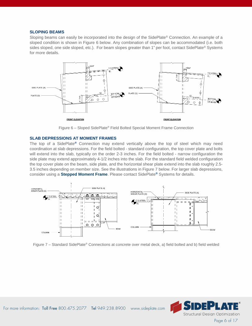
SLOPING BEAMS Sloping beams can easily be incorporated into the design of the SidePlate® Connection. An example of a sloped condition is shown in Figure 6 below. Any combination of slopes can be accommodated (i.e. both sides sloped, one side sloped, etc.). For beam slopes greater than 1” per foot, contact SidePlate® Systems for more details.
Figure 6 – Sloped SidePlate® Field Bolted Special Moment Frame Connection SLAB DEPRESSIONS AT MOMENT FRAMES The top of a SidePlate® Connection may extend vertically above the top of steel which may need coordination at slab depressions. For the field bolted - standard configuration, the top cover plate and bolts will extend into the slab, typically on the order 2-3 inches. For the field bolted - narrow configuration the side plate may extend approximately 4-1/2 inches into the slab. For the standard field welded configuration the top cover plate on the beam, side plate, and the horizontal shear plate extend into the slab roughly 2.5-3.5 inches depending on member size. See the illustrations in Figure 7 below. For larger slab depressions, consider using a Stepped Moment Frame. Please contact SidePlate® Systems for details.
Figure 7 – Standard SidePlate® Connections at concrete over metal deck, a) field bolted and b) field welded
For more information: Toll Free 800.475.2077 Tel 949.238.8900 www.sideplate.com
Page 7 of 17
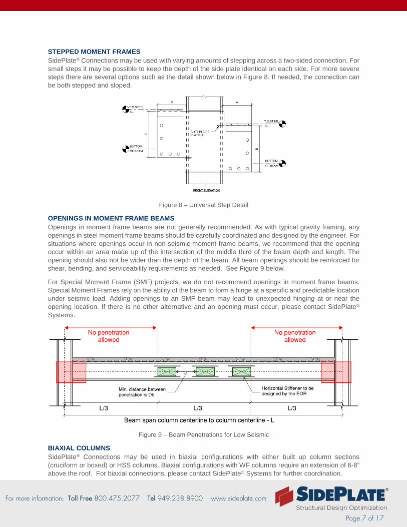
STEPPED MOMENT FRAMES SidePlate® Connections may be used with varying amounts of stepping across a two-sided connection. For small steps it may be possible to keep the depth of the side plate identical on each side. For more severe steps there are several options such as the detail shown below in Figure 8. If needed, the connection can be both stepped and sloped.
Figure 8 – Universal Step Detail
OPENINGS IN MOMENT FRAME BEAMS Openings in moment frame beams are not generally recommended. As with typical gravity framing, any openings in steel moment frame beams should be carefully coordinated and designed by the engineer. For situations where openings occur in non-seismic moment frame beams, we recommend that the opening occur within an area made up of the intersection of the middle third of the beam depth and length. The opening should also not be wider than the depth of the beam. All beam openings should be reinforced for shear, bending, and serviceability requirements as needed. See Figure 9 below.
For Special Moment Frame (SMF) projects, we do not recommend openings in moment frame beams. Special Moment Frames rely on the ability of the beam to form a hinge at a specific and predictable location under seismic load. Adding openings to an SMF beam may lead to unexpected hinging at or near the opening location. If there is no other alternative and an opening must occur, please contact SidePlate® Systems.
Figure 9 – Beam Penetrations for Low Seismic
BIAXIAL COLUMNS SidePlate® Connections may be used in biaxial configurations with either built up column sections (cruciform or boxed) or HSS columns. Biaxial configurations with WF columns require an extension of 6-8” above the roof. For biaxial connections, please contact SidePlate® Systems for further coordination.
For more information: Toll Free 800.475.2077 Tel 949.238.8900 www.sideplate.com
Page 8 of 17
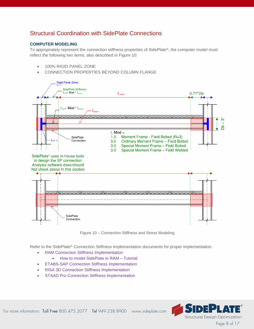
Structural Coordination with SidePlate Connections
COMPUTER MODELING To appropriately represent the connection stiffness properties of SidePlate®, the computer model must reflect the following two items, also described in Figure 10:
• 100% RIGID PANEL ZONE • CONNECTION PROPERTIES BEYOND COLUMN FLANGE
Figure 10 – Connection Stiffness and Stress Modeling
Refer to the SidePlate® Connection Stiffness Implementation documents for proper implementation.
• RAM Connection Stiffness Implementation • How to model SidePlate in RAM – Tutorial
• ETABS-SAP Connection Stiffness Implementation • RISA 3D Connection Stiffness Implementation • STAAD Pro Connection Stiffness Implementation
For more information: Toll Free 800.475.2077 Tel 949.238.8900 www.sideplate.com
Page 9 of 17
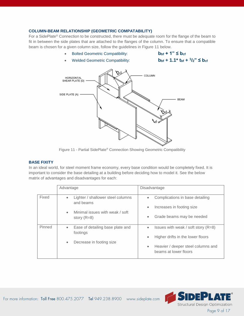
COLUMN-BEAM RELATIONSHIP (GEOMETRIC COMPATABILITY) For a SidePlate® Connection to be constructed, there must be adequate room for the flange of the beam to fit in between the side plates that are attached to the flanges of the column. To ensure that a compatible beam is chosen for a given column size, follow the guidelines in Figure 11 below.
• Bolted Geometric Compatibility: bbf + 1” ≤ bcf • Welded Geometric Compatibility: bbf + 1.1* tbf + 1/2” ≤ bcf
Figure 11 - Partial SidePlate® Connection Showing Geometric Compatibility
BASE FIXITY In an ideal world, for steel moment frame economy, every base condition would be completely fixed. It is important to consider the base detailing at a building before deciding how to model it. See the below matrix of advantages and disadvantages for each:
Advantage Disadvantage
Fixed • Lighter / shallower steel columns and beams
• Minimal issues with weak / soft story (R=8)
• Complications in base detailing
• Increases in footing size
• Grade beams may be needed
Pinned • Ease of detailing base plate and footings
• Decrease in footing size
• Issues with weak / soft story (R=8)
• Higher drifts in the lower floors
• Heavier / deeper steel columns and beams at lower floors
For more information: Toll Free 800.475.2077 Tel 949.238.8900 www.sideplate.com
Page 10 of 17
CANTILEVERS Cantilevers can be used at SidePlate® Connections whether they are framing into the face of the actual side plate or the moment frame column flange. In order to ensure that the best solution is provided and the detailing is clear, please coordinate these connections with SidePlate® Systems. Typical cantilever details fall into two main categories – those that are perpendicular, or run through the SidePlate® Connection, and those that are in-plane, or opposite of a one-sided SidePlate® Connection at the end of the frame.
In Plane / Parallel In-plane or parallel cantilever connections occur at the end of a moment frame. These cantilever stubs often use complete joint penetration (CJP) welding of the beam flange to the column flange and rely on continuity plates between the column flanges. Although this configuration can often be used without interfering with the SidePlate® connection, some beams widths or offsets from the column center line will require detailing coordination.
Out of Plane / Perpendicular Out of plane or perpendicular cantilever connections may occur at any point along the moment frame. Where these connections occur at the SidePlate® Connection on the column, they must be coordinated with SidePlate® Systems. Provide the cantilever and backspan beam sizes as well as the loading (if it is not taken from the analysis software) and precise location (if other than centered).
COLLECTORS AND CHORDS In some configurations of moment frames, the load path for chords, collectors, or other axially loaded members will need to pass through or into the SidePlate® Connection. Coordination of these details will be similar to the coordination of cantilevers and will rely on the configuration of the engineer’s details.
In Plane / Parallel Unless the detailing will conflict with the SidePlate® Connection, there is not a need for coordination. It is often assumed that the complete collector force occurs at the end of the moment frame.
Out of Plane / Perpendicular Out of plane or perpendicular drag connections must be coordinated with SidePlate® Systems in the same way out of plane cantilevers are. In order to coordinate the design of these connections, SidePlate will need to know the collector or chord beam sizes as well as the axial force, and the preferred type of detailing (whether it be through a shear tab, top flange welded, or another mechanism).
NOTE: In some instances changing the SidePlate® Connection to a two-sided connection for an in-plane cantilever may be more economical and/or easier to erect. Contact SidePlate® Systems to discuss the options.
NOTE: If a field bolted SidePlate® Connection is being used for the moment frame, the cantilever portion of the connection may not be field bolted.
For more information: Toll Free 800.475.2077 Tel 949.238.8900 www.sideplate.com
Page 11 of 17
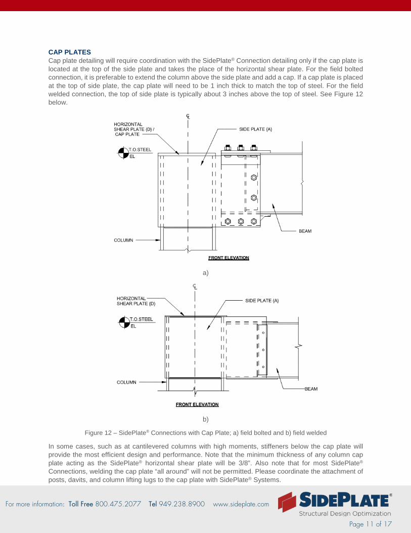
CAP PLATES Cap plate detailing will require coordination with the SidePlate® Connection detailing only if the cap plate is located at the top of the side plate and takes the place of the horizontal shear plate. For the field bolted connection, it is preferable to extend the column above the side plate and add a cap. If a cap plate is placed at the top of side plate, the cap plate will need to be 1 inch thick to match the top of steel. For the field welded connection, the top of side plate is typically about 3 inches above the top of steel. See Figure 12 below.
a)
b)
Figure 12 – SidePlate® Connections with Cap Plate; a) field bolted and b) field welded
In some cases, such as at cantilevered columns with high moments, stiffeners below the cap plate will provide the most efficient design and performance. Note that the minimum thickness of any column cap plate acting as the SidePlate® horizontal shear plate will be 3/8”. Also note that for most SidePlate® Connections, welding the cap plate “all around” will not be permitted. Please coordinate the attachment of posts, davits, and column lifting lugs to the cap plate with SidePlate® Systems.
For more information: Toll Free 800.475.2077 Tel 949.238.8900 www.sideplate.com
Page 12 of 17
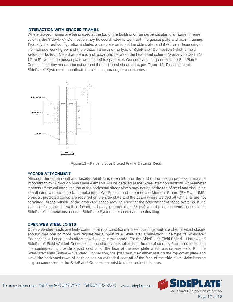
INTERACTION WITH BRACED FRAMES Where braced frames are being used at the top of the building or run perpendicular to a moment frame column, the SidePlate® Connection may be coordinated to work with the gusset plate and beam framing. Typically the roof configuration includes a cap plate on top of the side plate, and it will vary depending on the intended working point of the braced frame and the type of SidePlate® Connection (whether field welded or bolted). Note that there is a physical gap between the beam and column (typically between 1-1/2 to 5”) which the gusset plate would need to span over. Gusset plates perpendicular to SidePlate® Connections may need to be cut around the horizontal shear plate, per Figure 13. Please contact SidePlate® Systems to coordinate details incorporating braced frames.
Figure 13 – Perpendicular Braced Frame Elevation Detail
FACADE ATTACHMENT Although the curtain wall and façade detailing is often left until the end of the design process, it may be important to think through how these elements will be detailed at the SidePlate® connections. At perimeter moment frame columns, the top of the horizontal shear plates may not be at the top of steel and should be coordinated with the façade manufacturer. On Special and Intermediate Moment Frame (SMF and IMF) projects, protected zones are required on the side plate and the beam where welded attachments are not permitted. Areas outside of the protected zones may be used for the attachment of these systems. If the loading of the curtain wall or façade is heavy (greater than 25 psf) and the attachments occur at the SidePlate® connections, contact SidePlate Systems to coordinate the detailing.
OPEN WEB STEEL JOISTS Open web steel joists are fairly common at roof conditions in steel buildings and are often spaced closely enough that one or more may require the support of a SidePlate® Connection. The type of SidePlate® Connection will once again affect how the joist is supported. For the SidePlate® Field Bolted – Narrow and SidePlate® Field Welded Connections, the side plate is taller than the top of steel by 3 or more inches. In this configuration, provide a joist seat off of the face of the side plate which avoids any bolts. For the SidePlate® Field Bolted – Standard Connection, the joist seat may either rest on the top cover plate and avoid the horizontal rows of bolts or use an extended seat off of the face of the side plate. Joist bracing may be connected to the SidePlate® Connection outside of the protected zones.
For more information: Toll Free 800.475.2077 Tel 949.238.8900 www.sideplate.com
Page 13 of 17
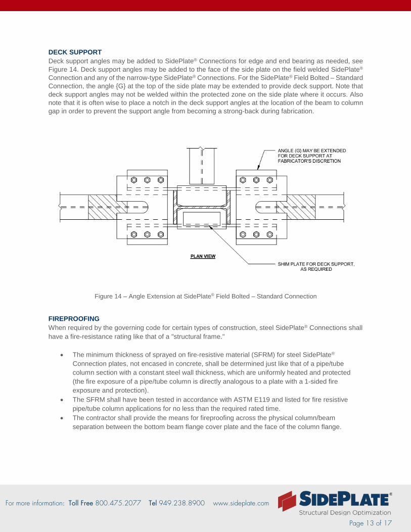
DECK SUPPORT Deck support angles may be added to SidePlate® Connections for edge and end bearing as needed, see Figure 14. Deck support angles may be added to the face of the side plate on the field welded SidePlate® Connection and any of the narrow-type SidePlate® Connections. For the SidePlate® Field Bolted – Standard Connection, the angle {G} at the top of the side plate may be extended to provide deck support. Note that deck support angles may not be welded within the protected zone on the side plate where it occurs. Also note that it is often wise to place a notch in the deck support angles at the location of the beam to column gap in order to prevent the support angle from becoming a strong-back during fabrication.
Figure 14 – Angle Extension at SidePlate® Field Bolted – Standard Connection
FIREPROOFING When required by the governing code for certain types of construction, steel SidePlate® Connections shall have a fire-resistance rating like that of a "structural frame."
• The minimum thickness of sprayed on fire-resistive material (SFRM) for steel SidePlate® Connection plates, not encased in concrete, shall be determined just like that of a pipe/tube column section with a constant steel wall thickness, which are uniformly heated and protected (the fire exposure of a pipe/tube column is directly analogous to a plate with a 1-sided fire exposure and protection).
• The SFRM shall have been tested in accordance with ASTM E119 and listed for fire resistive pipe/tube column applications for no less than the required rated time.
• The contractor shall provide the means for fireproofing across the physical column/beam separation between the bottom beam flange cover plate and the face of the column flange.
For more information: Toll Free 800.475.2077 Tel 949.238.8900 www.sideplate.com
Page 14 of 17
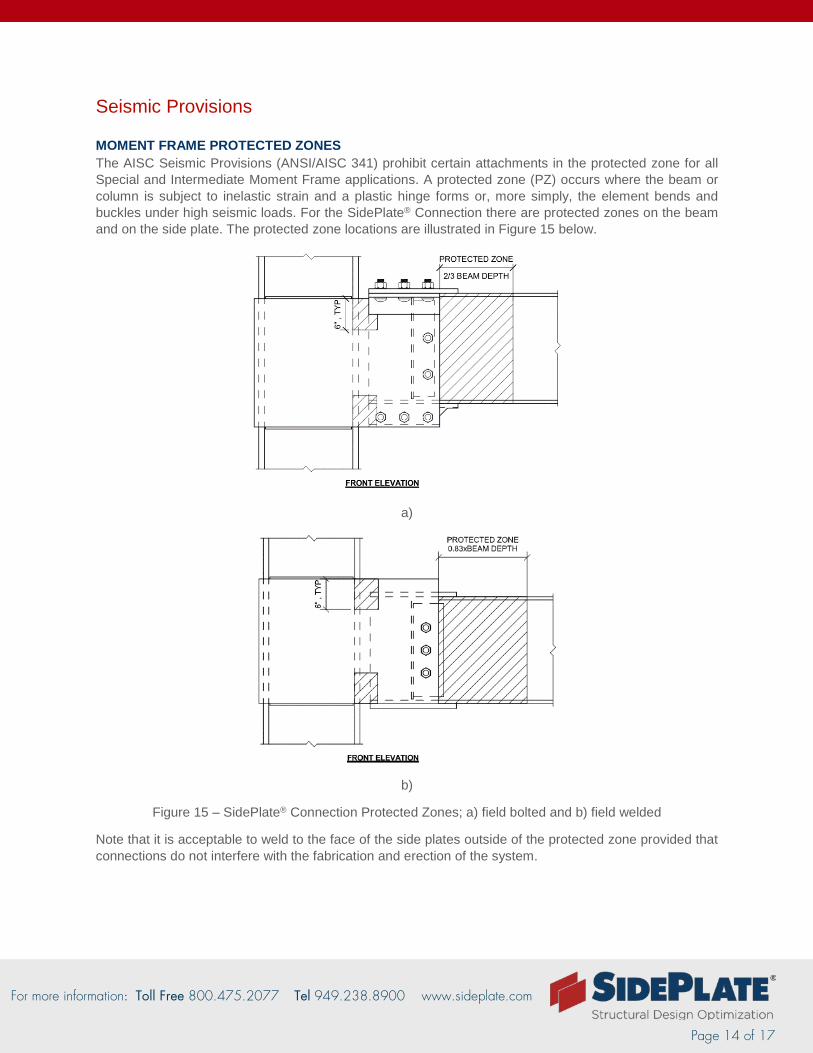
Seismic Provisions MOMENT FRAME PROTECTED ZONES The AISC Seismic Provisions (ANSI/AISC 341) prohibit certain attachments in the protected zone for all Special and Intermediate Moment Frame applications. A protected zone (PZ) occurs where the beam or column is subject to inelastic strain and a plastic hinge forms or, more simply, the element bends and buckles under high seismic loads. For the SidePlate® Connection there are protected zones on the beam and on the side plate. The protected zone locations are illustrated in Figure 15 below.
a)
b)
Figure 15 – SidePlate® Connection Protected Zones; a) field bolted and b) field welded
Note that it is acceptable to weld to the face of the side plates outside of the protected zone provided that connections do not interfere with the fabrication and erection of the system.
For more information: Toll Free 800.475.2077 Tel 949.238.8900 www.sideplate.com
Page 15 of 17
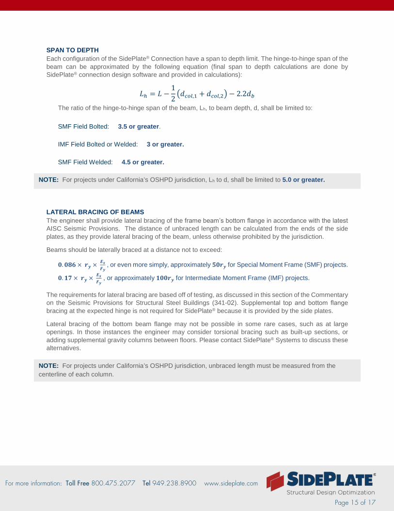
SPAN TO DEPTH Each configuration of the SidePlate® Connection have a span to depth limit. The hinge-to-hinge span of the beam can be approximated by the following equation (final span to depth calculations are done by SidePlate® connection design software and provided in calculations):
𝐿𝐿ℎ = 𝐿𝐿 −12�𝑑𝑑𝑐𝑐𝑐𝑐𝑐𝑐,1 + 𝑑𝑑𝑐𝑐𝑐𝑐𝑐𝑐,2� − 2.2𝑑𝑑𝑏𝑏
The ratio of the hinge-to-hinge span of the beam, Lh, to beam depth, d, shall be limited to: SMF Field Bolted: 3.5 or greater.
IMF Field Bolted or Welded: 3 or greater.
SMF Field Welded: 4.5 or greater.
LATERAL BRACING OF BEAMS The engineer shall provide lateral bracing of the frame beam’s bottom flange in accordance with the latest AISC Seismic Provisions. The distance of unbraced length can be calculated from the ends of the side plates, as they provide lateral bracing of the beam, unless otherwise prohibited by the jurisdiction.
Beams should be laterally braced at a distance not to exceed:
𝟎𝟎.𝟎𝟎𝟎𝟎𝟎𝟎 × 𝒓𝒓𝒚𝒚 × 𝑬𝑬𝒔𝒔𝑭𝑭𝒚𝒚
, or even more simply, approximately 𝟓𝟓𝟎𝟎𝒓𝒓𝒚𝒚 for Special Moment Frame (SMF) projects.
𝟎𝟎.𝟏𝟏𝟏𝟏 × 𝒓𝒓𝒚𝒚 × 𝑬𝑬𝒔𝒔𝑭𝑭𝒚𝒚
, or approximately 𝟏𝟏𝟎𝟎𝟎𝟎𝒓𝒓𝒚𝒚 for Intermediate Moment Frame (IMF) projects.
The requirements for lateral bracing are based off of testing, as discussed in this section of the Commentary on the Seismic Provisions for Structural Steel Buildings (341-02). Supplemental top and bottom flange bracing at the expected hinge is not required for SidePlate® because it is provided by the side plates.
Lateral bracing of the bottom beam flange may not be possible in some rare cases, such as at large openings. In those instances the engineer may consider torsional bracing such as built-up sections, or adding supplemental gravity columns between floors. Please contact SidePlate® Systems to discuss these alternatives.
NOTE: For projects under California’s OSHPD jurisdiction, unbraced length must be measured from the centerline of each column.
NOTE: For projects under California’s OSHPD jurisdiction, Lh to d, shall be limited to 5.0 or greater.
For more information: Toll Free 800.475.2077 Tel 949.238.8900 www.sideplate.com
Page 16 of 17
LATERAL JOINT BRACING Although AISC 341 requires lateral joint bracing at the top and bottom of beams in Special Moment Frames (SMF), these requirements do not apply to the SidePlate® Connection. Since there is a physical gap between the beam and the column, the load path does not use continuity plates at the joint, and localized buckling of the column is very unlikely. Additionally, the connection of the side plate to the column flanges provides additional stability at the joint. As a result, the SidePlate® Connection may be considered braced at the joint by simply providing a perpendicular beam shear tab connection within the joint region. At locations where no perpendicular framing occurs, the effects of a multi-story unbraced column should be considered, especially in weak axis bending and buckling outside of the SidePlate® Connection joint region.
PENTHOUSES A penthouse structure is meant to be an unoccupied space (likely for mechanical purposes) at the uppermost level of a structure. Per the IBC Section 1509.2, if a penthouse’s area is greater than 1/3 of the area of the story below, it must also be considered a story. If a structure has a penthouse level that does not meet these requirements (either it is occupied or it is greater than 1/3 the area), it should be considered a story. The uppermost story may use an alternate lateral system provided it meets the requirements of the code. It is important to note the exceptions to Table 12.2-1 in ASCE 7-10. If Special Moment Frames are selected as the lateral system for the penthouse level, the columns must be continuous to the base of the building.
For more information: Toll Free 800.475.2077 Tel 949.238.8900 www.sideplate.com
Page 17 of 17
Questions? SidePlate is here to help you! If you are considering using SidePlate Connections in your building, please send us your building model or frame layout for review, even if it is only schematic. We will run your model and layout through our connection design software to catch any flags or special checks and ensure that you have the best performing and most optimal lateral design for your client.
If your client is requesting a pricing exercise, we can also provide a pricing package containing detailed connection and steel take-off information.
Please feel free to contact SidePlate Systems at [email protected] anytime with questions or concerns.