Embed Size (px)
Citation preview
Concrete Paving Units for Roof DecksIntroductionAn increasing amount of new and rehabilitated roof decks use segmental concrete paving units to support pedestrian and vehicular applications. The units provide an attractive, durable walking surface for pedestrian plaza decks. They can be used to create outdoor space, usable exterior living environments at commercial and residential buildings e.g. next to offices, hotels, hospitals, universities, observation areas on commercial build-ings and at cultural centers. See Figure 1. Parking structures and the roof decks of underground buildings use concrete pavers to support vehicular traffic as shown in Figure 2.
Segmental concrete paving units protect roofing materials from damage due to foot traffic, equipment, hail and vehicles. Concrete provides a heat sink that reduces the thermal stress and deterioration of waterproofing materials. The units flex with the movement of the structure as well as with vehicular and seismic loads. Additionally, the units provide a slip-resistant surface and are especially attractive when viewed from adjacent buildings. They can exhibit high durability under freeze-thaw and deicing salt conditions.
A primary role of segmental concrete units is ballast for roof-ing materials to prevent uplift from high winds. When caught by high winds, gravel ballast on roofs can shift and distribute unevenly. This leaves roof materials exposed to winds, thereby increasing the risk of their uplift. In some cases the gravel can be blown from roofs creating a hazard for glass, pedestrians
Figure 1. Concrete pavers provide a durable and attractive roof plaza deck sur-face. At left is the observation deck on the 86th floor of Empire State Building in New York City. At center is a hotel plaza deck constructed with concrete paving slabs.
© 2002 ICPI Tech Spec No. 14 • Interlocking Concrete Pavement Institute • Revised April 2008 • All rights reserved.
Figure 2. Concrete pavers serve vehicular traf-fic and parking over a concrete parking struc-ture next to a residential development.
and vehicles. Concrete units are preferred over gravel ballast because they provide a consistent, evenly distributed weight for protection from wind uplift and damage. Furthermore, concrete unit paving is required by many building codes as roof ballast for high-rise buildings.
This Tech Spec provides guidance on the design and con-struction of roof assemblies using precast concrete pavers or concrete paving slabs using with various setting methods for pedestrian and vehicular applications. There are many kinds of roof assemblies placed under these types of paving units. The compatibility of paving units and setting methods with the com-ponents of roofing assemblies such as waterproof membrane, protection board and insulation should always be verified with the manufacturers of such components.
Vegetated, low-slope roof surfaces or “green roofs” are receiving increased attention from designers and clients inter-ested in reducing building energy costs and the urban heat island. This trend is changing the aerial view of our cities. Furthermore, sustainable building rating systems such as LEED® recognize green roof technology as well as highly reflective roof surfaces. Concrete unit paving offers designers a reflective surface that can be easily integrated into green roof projects while earning LEED® credits. ICPI Tech Spec 16-Acheiving LEED® Credits with Segmental Concrete Pavement provides additional information on how to integrate green roofs with concrete unit paving.
T E C H S P E C
N U m b E R 1 4
ICPI Tech Spec 14 Page 2
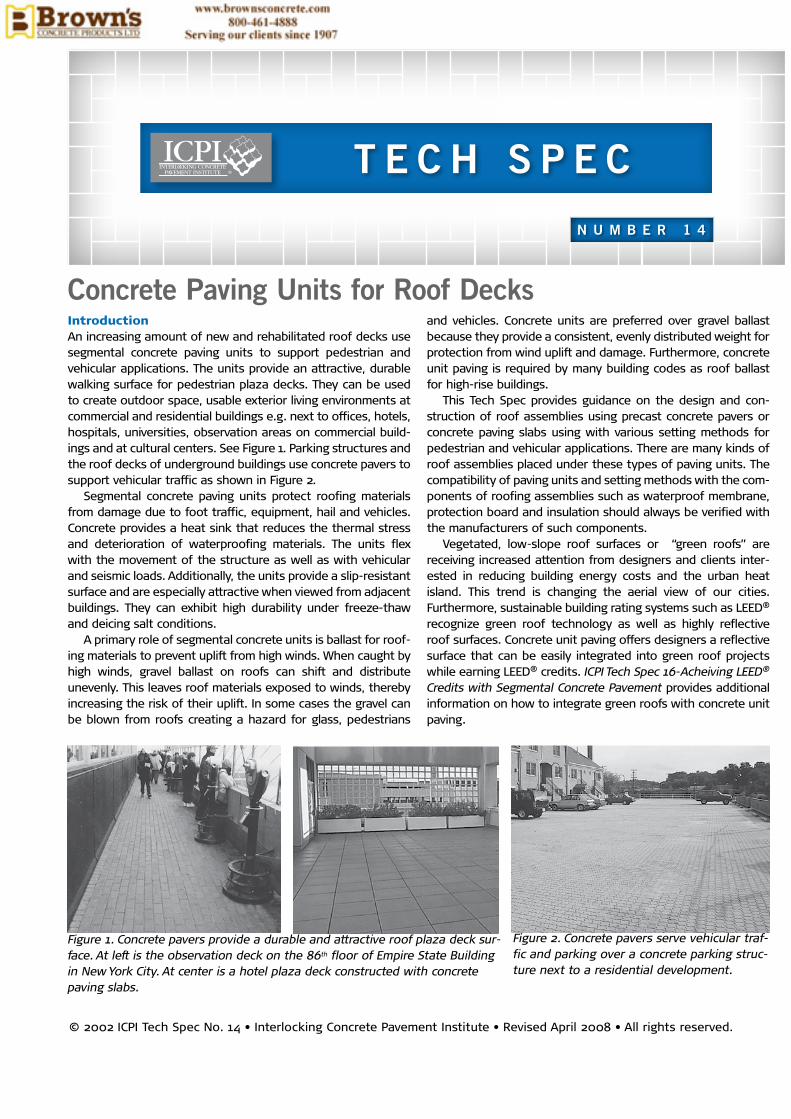
Plaza Deck ComponentsConcrete pavers and slabs—There are two categories of seg-mental concrete deck materials for roofs, concrete pavers and slabs. See Figure 3. Concrete pavers are units that are a minimum thickness of 23/8 in. (60 mm) and whose length to thickness (aspect ratio) does not exceed 4 to 1. They conform to the requirements of ASTM C 936 (1) in the U.S. or CSA A231.2 (2) in Canada. These units can be used in pedestrian and vehicular applications. Concrete pavers 23/8 in. (60 mm) thick are commonly used in pedestrian plaza or terrace applications. When the capacity of the structure is limited to additional weight, units as thin as 11/2 in. (40 mm) have been used in pedestrian applications. For vehicular uses, the recommended minimum thickness of units is 31/8 in. (80 mm).
Precast concrete paving slabs range in nominal size from 10 x 10 in. (250 x 250 mm) to 36 x 36 in. (910 x 910 mm). Like pav-ers, concrete paving slabs can be manufactured with a variety of colors, special aggregates and architectural finishes to enhance their appearance. Surface finishes include shot-blast-ed, hammered and ground or polished. They differ from pavers in that slabs typically require at least two hands to lift and place them, and the length to thickness (aspect ratio) is 4 to 1 or greater. Paving slabs generally range in thickness from 11/2 in. to 2 in. (40 to 50 mm) and thicker units are also applied to roofs. Slabs are only for pedestrian plaza applications and are
Figure 3. Concrete paver (left) and a concrete paving slab (right): similar paving products with varying applications for roof decks.
not recommended for vehicular use. Slabs risk tipping, cracking from bending forces, and shift-ing under repeated forc-es from turning and brak-ing tires.
Concrete paving slabs made in Canada should conform to CSA A231.1 (3). This standard applies to paving slabs used on roofs as well as at-grade construction. The stan-dard requires a minimum average flexural (bend-
ing) strength of 650 psi (4.5 MPa), freeze-thaw durability when exposed to deicing salts and conformance to dimensional toler-ances. Flexural (rather than compressive strength) is used to assess unit strength since the larger slabs are exposed to bend-ing and cracking. Compressive strength is excluded from the standard because it is not a true measure of the performance of the concrete. It can increase as the thickness of the tested unit decreases. Therefore, a high compressive strength test result required from a thin slab gives a false indication of a slab’s resistance to bending since thinner slabs will break in bending more readily than thicker ones.
Unit dimensions are measured on samples and compared to the dimensions of the manufacturer’s product drawings. Allowable tolerances for length and width in CSA A231.1 are –1.0 to +2.0 mm from the manufacturer’s product drawings. Height should not vary ±3.0 mm. Units should not warp more than 2 mm on those up to 450 mm in length and/or width. For units over 450 mm, warping should not exceed 3 mm. There is no standard for precast concrete paving slabs in the U.S.
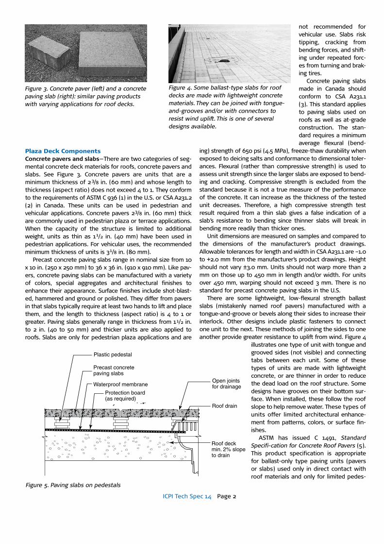
There are some lightweight, low-flexural strength ballast slabs (mistakenly named roof pavers) manufactured with a tongue-and-groove or bevels along their sides to increase their interlock. Other designs include plastic fasteners to connect one unit to the next. These methods of joining the sides to one another provide greater resistance to uplift from wind. Figure 4
illustrates one type of unit with tongue and grooved sides (not visible) and connecting tabs between each unit. Some of these types of units are made with lightweight concrete, or are thinner in order to reduce the dead load on the roof structure. Some designs have grooves on their bottom sur-face. When installed, these follow the roof slope to help remove water. These types of units offer limited architectural enhance-ment from patterns, colors, or surface fin-ishes.
ASTM has issued C 1491, Standard Specifi-cation for Concrete Roof Pavers (5). This product specification is appropriate for ballast-only type paving units (pavers or slabs) used only in direct contact with roof materials and only for limited pedes-
Figure 4. Some ballast-type slabs for roof decks are made with lightweight concrete materials. They can be joined with tongue-and-grooves and/or with connectors to resist wind uplift. This is one of several designs available.
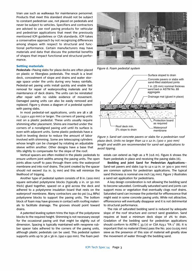
Precast concrete paving slabs
Open joints for drainage
Roof drain
Plastic pedestal
Protection board (as required)
Waterproof membrane
Roof deckmin. 2% slope to drain
Figure 5Figure 5. Paving slabs on pedestals
ICPI Tech Spec 14 Page 3
trian use such as walkways for maintenance personnel. Products that meet this standard should not be subject to constant pedestrian use, not placed on pedestals and never be subject to vehicles. Specifiers and contractors are advised to use roof paving products for vehicular and pedestrian applications that meet the previously mentioned ICPI guidelines or CSA standards. ICPI takes a conservative approach by not recognizing differences among shapes with respect to structural and func-tional performance. Certain manufacturers may have materials and data that discuss the potential benefits of shapes that impact functional and structural perfor-mance.
Setting materials Pedestals—Paving slabs for plaza decks are often placed on plastic or fiberglass pedestals. The result is a level deck, concealment of slope and drains and water stor-age space under the units during very heavy rainfalls. Pedestal-set paving units install quickly and enable fast removal for repair of waterproofing materials and for maintenance of deck drains. The units can be reinstated after repair with no visible evidence of movement. Damaged paving units can also be easily removed and replaced. Figure 5 shows a diagram of a pedestal system with paving slabs.
In most pedestal-set applications, units are 18 x 18 in. (450 x 450 mm) or larger. The corners of paving units rest on a plastic pedestal. These units usually require shimming after placement. Shims are inserted under the corners of a nonaligned paving unit until its surface is even with adjacent units. Some plastic pedestals have a built-in leveling device to reduce the amount of labor involved with shimming. Some are telescoping cylinders whose length can be changed by rotating an adjustable sleeve within another. Other designs have a base that tilts slightly to compensate for the slope of the roof.
Vertical spacers are often molded in the plastic pedestals to ensure uniform joint widths among the paving units. The open joints allow runoff to pass through them onto the waterproof membrane and into roof drains. The joint created by the spacer should not exceed 3/16 in. (5 mm) and this will minimize the likelihood of tripping.
Another type of pedestal system consists of 8 in. (200 mm) square extruded polystyrene blocks (typically 2 in. or 50 mm thick) glued together, spaced on a grid across the deck and adhered to a polystyrene insulation board that rests on the waterproof membrane. Many contractors use 60 psi (0.4 MPa) polystyrene blocks to support the paving units. The bottom block of foam may have grooves in contact with roofing materi-als to facilitate drainage. The grooves should point toward drains.
A patented leveling system trims the tops of the polystyrene blocks to the required height. Shimming is not necessary except for the occasional paving unit that might be slightly out of dimension. Spacing is typically maintained with neoprene rub-ber spacer tabs adhered to the corners of the paving units, although plastic pedestals can be used. This pedestal system supports units up to 36 x 36 in. (910 x 910 mm). The foam ped-
estals can extend as high as 2 ft (0.6 m). Figure 6 shows the foam pedestals in place and receiving the paving slabs (6).
Bedding and Joint Sand for Pedestrian Applications—Sand-set pavers and slabs (up to 12 x 12 in. or 300 x 300 mm) are common options for pedestrian applications. The typical sand thickness is nominal one inch (25 mm). Figure 7 illustrates a sand-set application for pedestrians.
A key design consideration is not allowing the bedding sand to become saturated. Continually saturated sand and joints can support moss or vegetation that eventually clogs roof drains. Saturated sand can increase the potential for efflorescence that might exist in some concrete paving units. While not attractive, efflorescence will eventually disappear and it is not detrimental to structural performance.
The risk of saturated bedding sand is reduced by adequate slope of the roof structure and correct sand gradation. Sand requires at least a minimum deck slope of 2% to drain. Gradation of the bedding sand for pedestrian applications should conform to ASTM C 33 (7) or CSA A23.1 “FA 1” (8). It is important that no material (fines) pass the No. 200 (0.075 mm) sieve as the presence of this size of material will greatly slow the movement of water through the bedding sand.
Figure 6. Foam pedestal system
Surface sloped to drain
Concrete pavers or slabs with sand-filled stabilized joints
1 in. (25 mm) nominal thicknes sand bed or ASTM No. 89 aggregate
Drainage mat (glued in place)
Protection board as required
Waterproof membrane
Roof deck min. 2% slope to drain
Figure 7. Sand-set concrete pavers or slabs for a pedestrian roof plaza deck. Units no larger than 12 x 12 in. (300 x 300 mm) length and width are recommended for sand-set applications to avoid tipping.
ICPI Tech Spec 14 Page 4
With any segmental paving system, the final, installed result should provide a smooth, stable, and even surface. For pedestrian plaza deck applications, lipping tolerances among adjacent paving units should be no greater than 1/8 in. (3 mm). Surface tolerances of the finished eleva-
tions should be no greater than ±1/8 in. (±3 mm).
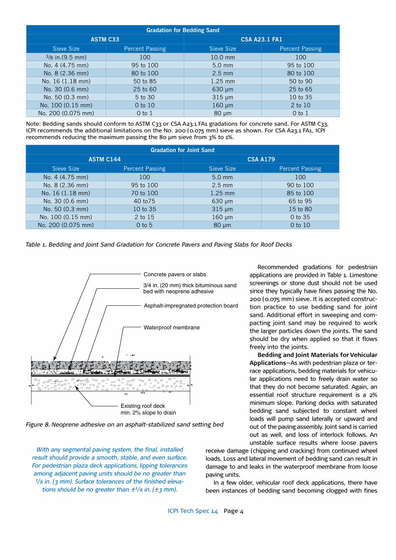
Recommended gradations for pedestrian applications are provided in Table 1. Limestone screenings or stone dust should not be used since they typically have fines passing the No. 200 (0.075 mm) sieve. It is accepted construc-tion practice to use bedding sand for joint sand. Additional effort in sweeping and com-pacting joint sand may be required to work the larger particles down the joints. The sand should be dry when applied so that it flows freely into the joints.
Bedding and Joint Materials for Vehicular Applications—As with pedestrian plaza or ter-race applications, bedding materials for vehicu-lar applications need to freely drain water so that they do not become saturated. Again, an essential roof structure requirement is a 2% minimum slope. Parking decks with saturated bedding sand subjected to constant wheel loads will pump sand laterally or upward and out of the paving assembly. Joint sand is carried out as well, and loss of interlock follows. An unstable surface results where loose pavers
receive damage (chipping and cracking) from continued wheel loads. Loss and lateral movement of bedding sand can result in damage to and leaks in the waterproof membrane from loose paving units.
In a few older, vehicular roof deck applications, there have been instances of bedding sand becoming clogged with fines
Concrete pavers or slabs
3/4 in. (20 mm) thick bituminous sand bed with neoprene adhesive
Asphalt-impregnated protection board
Waterproof membrane
Existing roof deck min. 2% slope to drain
Figure 8
Figure 8. Neoprene adhesive on an asphalt-stabilized sand setting bed
Gradation for bedding Sand
ASTm C33 CSA A23.1 FA1
Sieve Size Percent Passing Sieve Size Percent Passing 3/8 in.(9.5 mm) 100 10.0 mm 100
No. 4 (4.75 mm) 95 to 100 5.0 mm 95 to 100 No. 8 (2.36 mm) 80 to 100 2.5 mm 80 to 100
No. 16 (1.18 mm) 50 to 85 1.25 mm 50 to 90 No. 30 (0.6 mm) 25 to 60 630 µm 25 to 65 No. 50 (0.3 mm) 5 to 30 315 µm 10 to 35
No. 100 (0.15 mm) 0 to 10 160 µm 2 to 10 No. 200 (0.075 mm) 0 to 1 80 µm 0 to 1
Gradation for Joint Sand
ASTm C144 CSA A179
Sieve Size Percent Passing Sieve Size Percent Passing No. 4 (4.75 mm) 100 5.0 mm 100No. 8 (2.36 mm) 95 to 100 2.5 mm 90 to 100
No. 16 (1.18 mm) 70 to 100 1.25 mm 85 to 100No. 30 (0.6 mm) 40 to75 630 µm 65 to 95 No. 50 (0.3 mm) 10 to 35 315 µm 15 to 80
No. 100 (0.15 mm) 2 to 15 160 µm 0 to 35 No. 200 (0.075 mm) 0 to 5 80 µm 0 to 10
Note: Bedding sands should conform to ASTM C33 or CSA A23.1 FA1 gradations for concrete sand. For ASTM C33, ICPI recommends the additional limitations on the No. 200 (0.075 mm) sieve as shown. For CSA A23.1 FA1, ICPI recommends reducing the maximum passing the 80 μm sieve from 3% to 1%.
Table 1. Bedding and Joint Sand Gradation for Concrete Pavers and Paving Slabs for Roof Decks
ICPI Tech Spec 14 Page 5
over several years. The source of fines is likely from a combina-tion of a lack of adequate slope, dirt deposited from vehicles and sometimes from degradation and wearing of the sand into finer material under constant traffic. The fines eventually accu-mulate in the bedding sand and slow drainage.
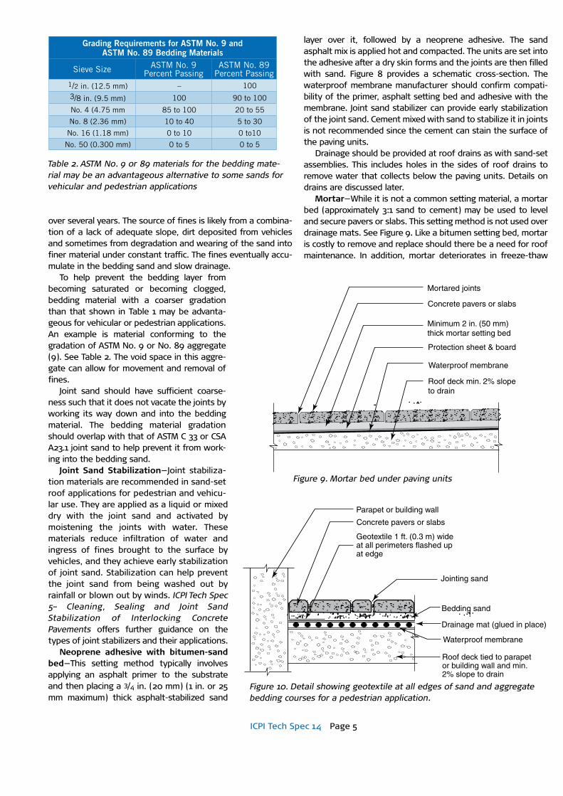
To help prevent the bedding layer from becoming saturated or becoming clogged, bedding material with a coarser gradation than that shown in Table 1 may be advanta-geous for vehicular or pedestrian applications. An example is material conforming to the gradation of ASTM No. 9 or No. 89 aggregate (9). See Table 2. The void space in this aggre-gate can allow for movement and removal of fines.
Joint sand should have sufficient coarse-ness such that it does not vacate the joints by working its way down and into the bedding material. The bedding material gradation should overlap with that of ASTM C 33 or CSA A23.1 joint sand to help prevent it from work-ing into the bedding sand.
Joint Sand Stabilization—Joint stabiliza-tion materials are recommended in sand-set roof applications for pedestrian and vehicu-lar use. They are applied as a liquid or mixed dry with the joint sand and activated by moistening the joints with water. These materials reduce infiltration of water and ingress of fines brought to the surface by vehicles, and they achieve early stabilization of joint sand. Stabilization can help prevent the joint sand from being washed out by rainfall or blown out by winds. ICPI Tech Spec 5– Cleaning, Sealing and Joint Sand Stabilization of Interlocking Concrete Pavements offers further guidance on the types of joint stabilizers and their applications.
Neoprene adhesive with bitumen-sand bed—This setting method typically involves applying an asphalt primer to the substrate and then placing a 3/4 in. (20 mm) (1 in. or 25 mm maximum) thick asphalt-stabilized sand
layer over it, followed by a neoprene adhesive. The sand asphalt mix is applied hot and compacted. The units are set into the adhesive after a dry skin forms and the joints are then filled with sand. Figure 8 provides a schematic cross-section. The waterproof membrane manufacturer should confirm compati-bility of the primer, asphalt setting bed and adhesive with the membrane. Joint sand stabilizer can provide early stabilization of the joint sand. Cement mixed with sand to stabilize it in joints is not recommended since the cement can stain the surface of the paving units.
Drainage should be provided at roof drains as with sand-set assemblies. This includes holes in the sides of roof drains to remove water that collects below the paving units. Details on drains are discussed later.
Mortar—While it is not a common setting material, a mortar bed (approximately 3:1 sand to cement) may be used to level and secure pavers or slabs. This setting method is not used over drainage mats. See Figure 9. Like a bitumen setting bed, mortar is costly to remove and replace should there be a need for roof maintenance. In addition, mortar deteriorates in freeze-thaw
Table 2. ASTM No. 9 or 89 materials for the bedding mate-rial may be an advantageous alternative to some sands for vehicular and pedestrian applications
Concrete pavers or slabs
Mortared joints
Minimum 2 in. (50 mm) thick mortar setting bed
Protection sheet & board
Waterproof membrane
Roof deck min. 2% slope to drain
Figure 9.
Figure 9. Mortar bed under paving units
Parapet or building wall
Concrete pavers or slabs
Geotextile 1 ft. (0.3 m) wideat all perimeters flashed upat edge
Drainage mat (glued in place)
Bedding sand
Jointing sand
Waterproof membrane
Roof deck tied to parapet or building wall and min. 2% slope to drain
Figure 10. Figure 10. Detail showing geotextile at all edges of sand and aggregate bedding courses for a pedestrian application.
Grading Requirements for ASTm No. 9 and ASTm No. 89 bedding materials
Sieve Size ASTM No. 9Percent Passing
ASTM No. 89Percent Passing
1/2 in. (12.5 mm) – 1003/8 in. (9.5 mm) 100 90 to 100
No. 4 (4.75 mm 85 to 100 20 to 55
No. 8 (2.36 mm) 10 to 40 5 to 30
No. 16 (1.18 mm) 0 to 10 0 to10
No. 50 (0.300 mm) 0 to 5 0 to 5
ICPI Tech Spec 14 Page 6
climates, and especially when exposed to deicing salts. In ASTM C 270, Standard Specification for Mortar for Unit Masonry, the Appendices include a table on the Guide for the Selection of Masonry Mortars. While Type S is recommended, the guide states caution in selecting mortar for horizontal applications. While they are not foolproof, latex or epoxy modified mortars can reduce the onset of deterioration from freeze-thaw and salts making them acceptable for some pedestrian applica-tions. However, loading and environmental factors preclude the use of mortar-set paving units for vehicular applications, and this setting method is better suited for non-freezing areas.
Geotextiles, Protection Board, Insulation and Drainage MatsGeotextiles—With sand or aggregate bedding materials, geo-textile will be needed to contain them and keep them from migrating into deck drains or through wall drains such as scuppers. In addition, sand or aggregate requires geotextile under it to prevent loss into the protection board and insula-tion (if used). Geotextile manufacturers should be consulted on geotextile selection. The fabric should be turned up against drains, vents and other protrusions in the roof and along parapets and walls.
To contain sand and aggregate bedding materials, the geo-textile should extend up the side. Figure 10 shows this detail which will help prevent loss of bedding materials from a deluge of rainfall that causes temporary ponding around the drains. A separate piece of geotextile is wrapped around the roof drain to prevent loss of bedding sand or aggregate.
Protection board—Most waterproofing systems require a protection board over them to prevent damage to the water-proofing from paving units and to reduce thermal stresses from temperature changes. This can be an asphaltic protection board or other materials. The manufacturers of waterproofing systems can provide guidance on the use of protection layers and they can recommend specific materials when this option is required. Protection board is generally not used in vehicular applications.
Insulation—If a pedestrian plaza deck covers an inhabited space, insulation may be required. Insulation typically consists of foam or fiber boards placed over the waterproofing. Sometimes they are adhered directly to the waterproofing. Insulation may be tapered to roof drains to facilitate movement of water into the drains. Insulation board in contact with the waterproof membrane should have drainage channels to facili-tate drainage of water under it. Insulation under pavers in vehicular applications requires careful design and execution. As with other engineered pavements, consult an experienced designer familiar with these applications. A secure location for insulation is sandwiched in place inside the concrete deck.
Drainage mats—Drainage mats are generally placed under bedding sand and over waterproof membranes to accelerate drainage of water from the sand. Drainage mats are typically 1/4 to 3/8 in. (6 to 10 mm) thick. They consist of a plastic structure covered by geotextile. The structure and geotextile support and contain the bedding sand under the paving units while allowing water to move into it and laterally to roof drains. They are rec-ommended in pedestrian applications under a sand setting bed. They should be placed at a minimum of 2% slope.
Installation of drainage mats for pedestrian applications should start at the lowest slope on the roof with the work pro-ceeding upslope. Flaps on each should go under the next (in a manner similar to placing roof shingles) so that the water drains from one section to the next. This helps prevent water from leaking under the mats. While mats reduce the amount of water reaching the waterproof membrane, they are not a sub-stitute for deck waterproofing. The paving installation contrac-tor should install mats.
Drainage mats are typically supplied in rolls making them difficult to flatten, and they often don’t remain flat during instal-lation. An adhesive between the mat and waterproof mem-brane will likely be required to maintain flat drainage mats during their installation.
Drainage mats can be used under foam or plastic pedestal systems. While drainage mats may be tested according to the compressive strength test method in ASTM D 1621 (10), they may require additional testing by pre-loading to ensure that
they will not crush under loads from the ped-estals.
Drainage mats should not be used under vehicles. Mats deflect under wheel loads, eventually fatiguing, compressing and deform-ing. Repeated deflection tends to shift the pavers, bedding and joint sand, making inter-lock difficult to maintain. The deflection causes the joint sand to work its way into the bedding and the bedding sand shifts under loads, especially when saturated. The loss of joint and bedding sand, with possible even-tual crushing of the mat, retains water and this can saturate the bedding sand.
Waterproof MembranesThe choice of waterproofing is influenced by the application, the project budget, the deck materials under it and the type of structure supporting the roof. There are three broad
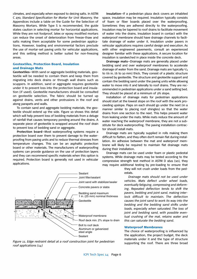
Aluminum or galvanized steel angle
Sealant
SealantJoint filler/sealant
Joint sand with stabilizer/sealer
Concrete pavers or slabs
Bedding sand maximum 1 in. (25 mm) nominal thickness
Waterproof membrane
Geotextile
Roof deck min. 2% slope to drain
Bolt to roof deck
Figure 11Figure 11. Edge restraint detail at a roof construction joint for pedestrian roof applications (14)
ICPI Tech Spec 14 Page 7
types of waterproofing materials used under concrete paving units. They are single-ply, liquid membranes, built-up or modified bitumen roofing. A brief description of these materi-als follows with their compatibility to segmental paving (11,12).
Single-ply roofing is strictly for pedestrian applications and it is the most widely used waterproofing. It is typically made from vulcanized (cured) elastomers such as ethylene propylene diene monomer (EPDM), neoprene, or butyl. These flexible sheets have excellent weathering properties, high elongation and puncture resistance. When assembled on a roof, the sheets are spliced together at the job site with an adhesive. The entire assembly of sheets can be loose-laid and ballast provided by paving units. They also can be partially or fully adhered, or mechanically fastened to the roof deck.
Another type of single-ply membranes includes non-vulca-nized elastomers such as polyisobutylene (PIB), chlorinated polyethylene (CPE), chlorosulfanated polyethylene (CSPE). These materials are usually reinforced with a polyester mat laminated between two plies. Thermoplastics such as polyvinyl chloride (PVC) sheets are heat welded in the field. Like the elastomers, PVC is loose-laid with ballast paving units, partially or fully adhered, or mechanically fastened to the deck material.
Rubberized asphalt membranes and polyethylene laminates have been used extensively to waterproof pedestrian plaza decks. Prefabricated sheets are made in small sheets and are spliced together in field. They generally are fully adhered to the concrete deck, so their longevity is highly dependent on the quality of the workmanship in splicing and on the smoothness and quality of the concrete.
Manufacturers of single-ply membranes should be contact-ed about the extent of warranties on the field splices under paving units. Additional measures may be necessary to protect the splices from the paving. This can include installation of a second, sacrificial membrane layer directly under the paving units.
Liquid applied membranes are installed either hot or cold depending on the materials. Rubberized asphalt membranes are hot applied to the concrete deck to form a continuous coat-ing with no seams. These are for pedestrian plaza decks only. Cold-applied liquid resins and elastomers such as polyurethane are generally suitable as waterproofing on concrete decks sub-ject to vehicular use. Sprayed-in-place polyurethane foam acts as an insulator and as waterproofing. The material is soft and is not recommended for use with concrete paving units.
Built-up roofing is made from paper, woven fabric or glass fiber mats, polyester mats or fabrics adhered together in alter-nating layers with bitumen or coal tar. The exterior surface of the layers is covered with bitumen or coal tar. Built-up roofs use concrete pavers or slabs as a walking surface to prevent wear and puncture of the membrane, especially around mechanical equipment. The use of pedestal systems should be avoided in built-up roofing due to the likelihood of indentations in the layered waterproofing materials.
Modified bitumen consists of plastic or rubber additives pressed into asphalt sheets. They are installed by heating the sheets with a torch and applying them to the deck substrate, or by mopping bitumen and securing them to the substrate with it. Some systems use cold cement or mastics to adhere
the sheets to the substrate. Some modified bitumen water-proofings create overlap “bumps” every yard (meter) or so. There can be an additional construction cost to avoid these when using a pedestal system. These systems do not require segmental paving ballast unless insulation needs to be secured in place. While these systems are generally compati-ble with concrete paving units in pedestrian applications, manufacturers should be contacted for verification of use with paving units under vehicular traffic.
Each of these waterproofing systems has advantages and disadvantages on speed of installation, costs, durability and manufacturer warranties. Many waterproof membrane manu-facturers require the use of roofing contractors that have been certified to install a particular manufacturer’s roofing system. The subject of roof waterproofing is large and outside the scope of this publication. There are many references on roofing and waterproofing systems. An overview is provided in Roofing—Design Criteria, Options, Selection (12). Other resources are publications by the National Roofing Contractors Association at http://www.nrca.net and the Roof Consultants Institute at http://www.rci-online.org.
Deck Structure Systems Concrete—There are four types of concrete deck structural systems (11). They are reinforced concrete slabs, post-ten-sioned slabs, pre-stressed precast elements such as “T” beams with a concrete topping, and concrete poured onto and formed by steel decks. Each type responds to waterproofing differently. For example, volumetric changes in reinforced con-crete slabs can cause reflective cracking in liquid-applied membranes and some fully adhered bituminous systems. Post-tensioned slabs are generally suited for liquid applied mem-branes because the slabs have a low amount of deflection and cracking. Loose-laid waterproofing systems are suited for over precast elements because they can accommodate the many joints in the deck, whereas liquid-applied and fully adhered membranes are prone to reflective cracking and splitting at joints.
In lighter, less expensive roofs, the concrete deck is poured onto and formed by a corrugated steel deck. In some cases the concrete is lightweight, i.e., weighing less per cubic foot or cubic meter than ordinary ready-mixed concrete. The weight of
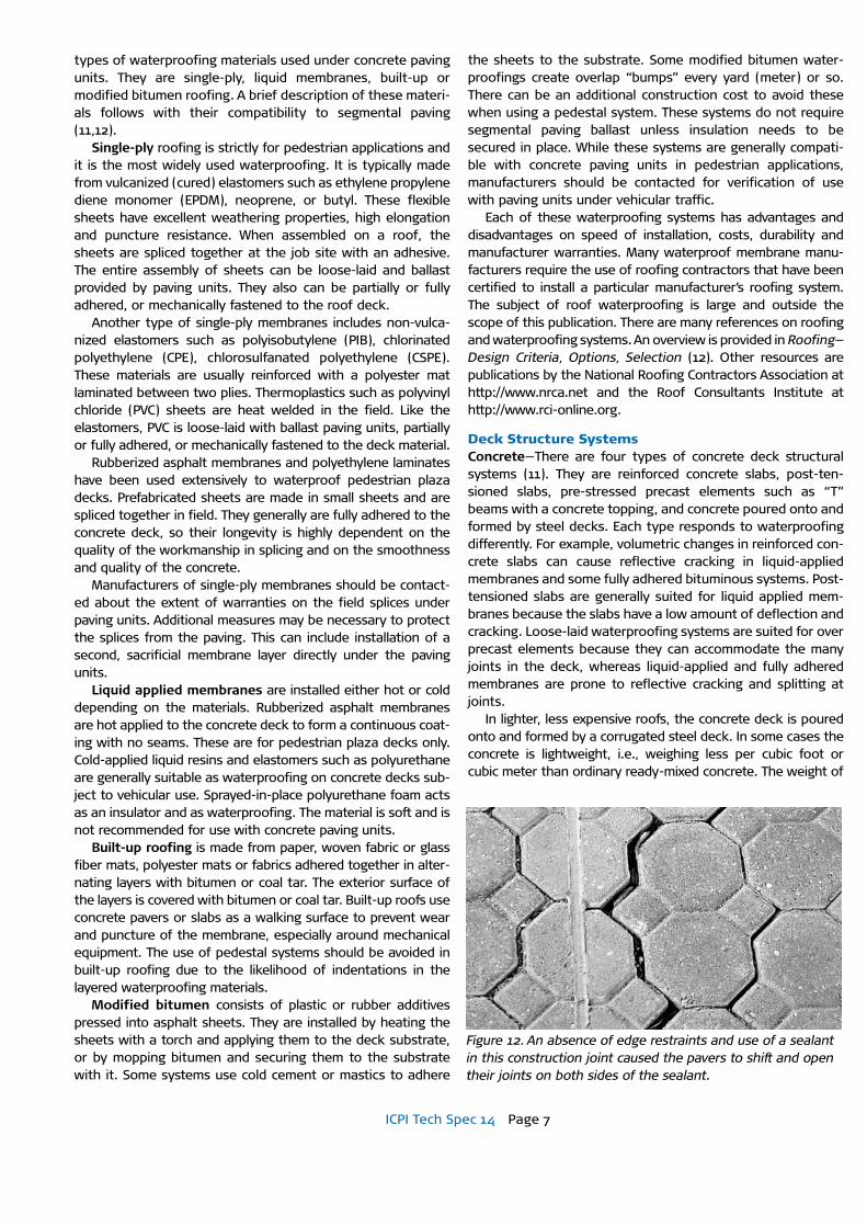
Figure 12. An absence of edge restraints and use of a sealant in this construction joint caused the pavers to shift and open their joints on both sides of the sealant.
ICPI Tech Spec 14 Page 8
Control joint material
Sealant
Concrete pavers or slabs (max. 12 x 12 in. or 300 x 300 mm)
Controljoint material
Geotextile 1 ft. (0.3 m) wideat all perimeters flashedup at edge
Drainage mat (glued in place)
Bedding sand
Waterproof membrane
Roof deck min. 2% slope to drain
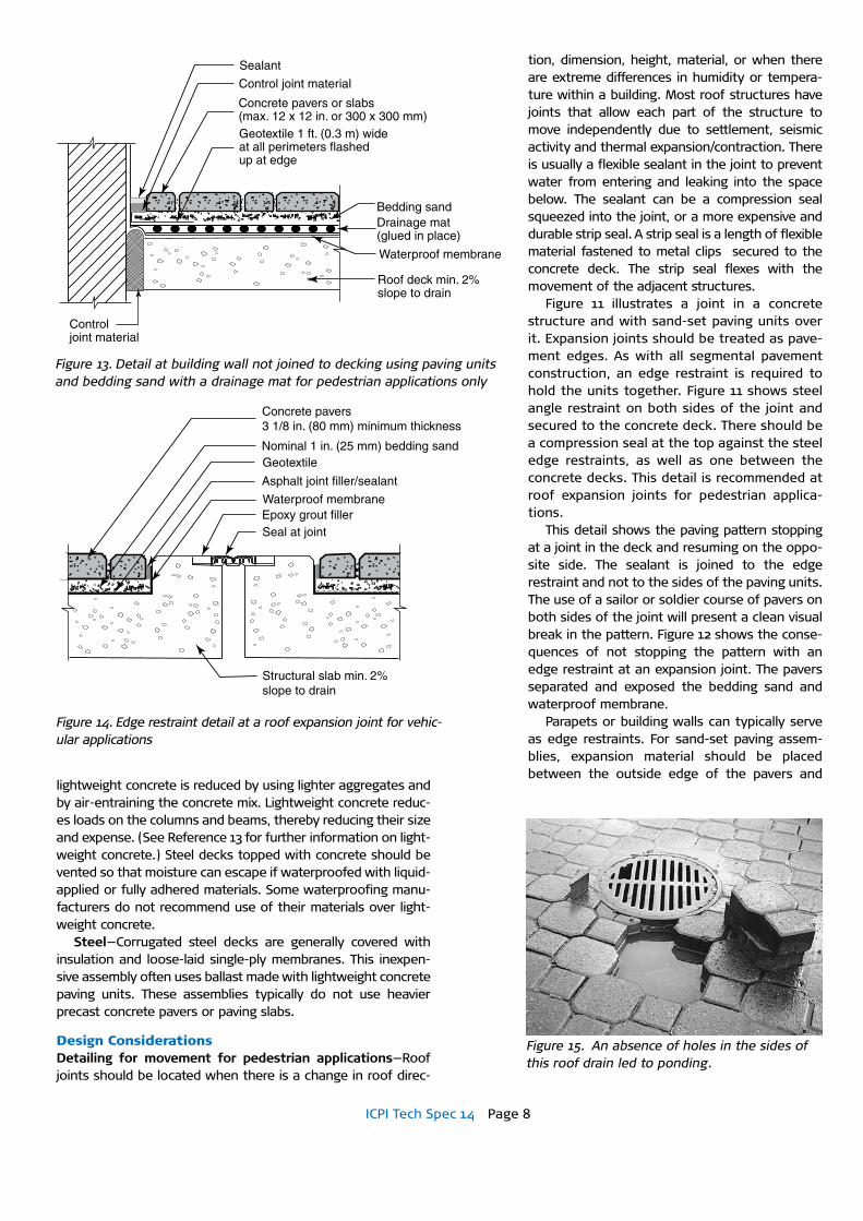
Figure13Figure 13. Detail at building wall not joined to decking using paving units and bedding sand with a drainage mat for pedestrian applications only
Figure14
Structural slab min. 2%slope to drain
Seal at jointEpoxy grout fillerWaterproof membrane
Asphalt joint filler/sealant
GeotextileNominal 1 in. (25 mm) bedding sand
Concrete pavers3 1/8 in. (80 mm) minimum thickness
Figure 14. Edge restraint detail at a roof expansion joint for vehic-ular applications
tion, dimension, height, material, or when there are extreme differences in humidity or tempera-ture within a building. Most roof structures have joints that allow each part of the structure to move independently due to settlement, seismic activity and thermal expansion/contraction. There is usually a flexible sealant in the joint to prevent water from entering and leaking into the space below. The sealant can be a compression seal squeezed into the joint, or a more expensive and durable strip seal. A strip seal is a length of flexible material fastened to metal clips secured to the concrete deck. The strip seal flexes with the movement of the adjacent structures.
Figure 11 illustrates a joint in a concrete structure and with sand-set paving units over it. Expansion joints should be treated as pave-ment edges. As with all segmental pavement construction, an edge restraint is required to hold the units together. Figure 11 shows steel angle restraint on both sides of the joint and secured to the concrete deck. There should be a compression seal at the top against the steel edge restraints, as well as one between the concrete decks. This detail is recommended at roof expansion joints for pedestrian applica-tions.
This detail shows the paving pattern stopping at a joint in the deck and resuming on the oppo-site side. The sealant is joined to the edge restraint and not to the sides of the paving units. The use of a sailor or soldier course of pavers on both sides of the joint will present a clean visual break in the pattern. Figure 12 shows the conse-quences of not stopping the pattern with an edge restraint at an expansion joint. The pavers separated and exposed the bedding sand and waterproof membrane.
Parapets or building walls can typically serve as edge restraints. For sand-set paving assem-blies, expansion material should be placed between the outside edge of the pavers and
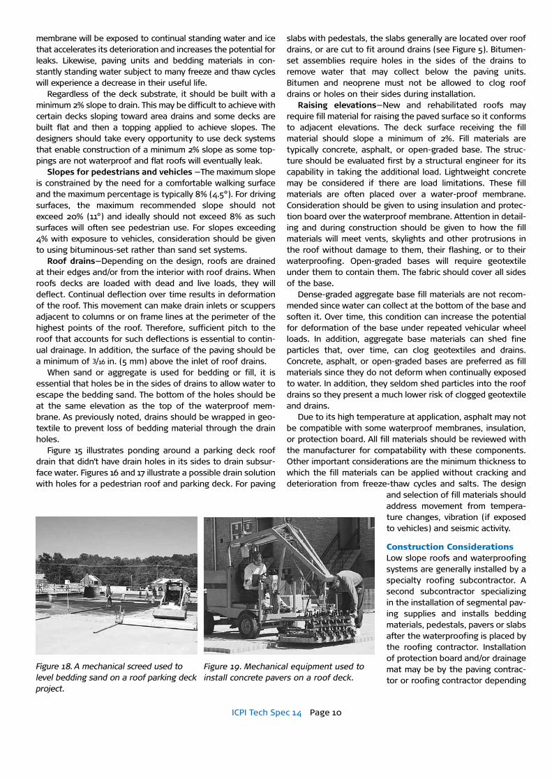
Figure 15. An absence of holes in the sides of this roof drain led to ponding.
lightweight concrete is reduced by using lighter aggregates and by air-entraining the concrete mix. Lightweight concrete reduc-es loads on the columns and beams, thereby reducing their size and expense. (See Reference 13 for further information on light-weight concrete.) Steel decks topped with concrete should be vented so that moisture can escape if waterproofed with liquid-applied or fully adhered materials. Some waterproofing manu-facturers do not recommend use of their materials over light-weight concrete.
Steel—Corrugated steel decks are generally covered with insulation and loose-laid single-ply membranes. This inexpen-sive assembly often uses ballast made with lightweight concrete paving units. These assemblies typically do not use heavier precast concrete pavers or paving slabs.
Design ConsiderationsDetailing for movement for pedestrian applications—Roof joints should be located when there is a change in roof direc-

ICPI Tech Spec 14 Page 9
vertical walls of buildings when functioning as separate structures from the deck on which the paving units rest. Figure 13 shows this detail with expansion material. It should not adhere to the paving units or the wall, but should inde-pendently expand and contract with their movement. Expansion materials at the perime-ter of the pavers are not necessary to place against walls or parapets when the pavers are resting on the same structure as the walls. Figure 10 illustrates this condition.
Detailing for movement for vehicular applications—Figure 14 details an expansion joint in a roof application subject to vehicles such as a parking structure. Although compres-sion seals can be used, this assembly uses a strip seal for bridging the joint. The ends of the concrete deck are formed as edge restraints to hold the concrete pavers in place.
23/8 in. (60 mm) vs. 31/8 in. (80 mm) thick pavers for vehicular applications—Most vehic-ular applications with pavers are supported by a concrete structure. The support from such a structure is often used as rationale for using pavers that are less than 3 1/2 in. (80 mm) thick. Thicker units render greater vertical and rota-tional interlock. Using concrete pavers less than 3 1/2 in. (80 mm) thick in vehicular of applica-tions increases the risk of reduced surface sta-bility by reducing horizontal and rotational interlock under turning and braking vehicles.
Weight—Concrete pavers, slabs and bedding materials exert substantial weight on roof structures. The structure supporting these materials should withstand dead and live loads. The advice of a structural engineer should be sought to assess the capacity of the roof and tolerable deflections from paving-related loads especially when units are added to an existing roof deck structure. The weight of paving units can be obtained from manufacturers for the purposes of calculating loads. Bedding sand (1 in. or 25 mm thick) weighs approximately 10 lbs. per sf (49 kg/m2).
Resistance to wind uplift—The designer should consult Loss Prevention Data for Roofing Contractors Data Sheets published by Factory Mutual (FM) Engineering Corporation (15). Data Sheets 1-28 and 1-29 provide design data includ-ing the minimum pounds per square foot (or kg/m2) of paving unit weight required for resis-tance to wind uplift. The FM charts consider wind velocity pressure on roofs at various heights in different geographic locations. Design pressures are then compared to the type of roof construction, parapet height and the whether the paving units have tongue-and-groove, beveled joints, or are strapped together. Some high wind regions may have local building codes with addi-tional weight requirements for paving units, especially on
high-rise buildings. Slope for drainage—A flat or “dead level” roof, i.e., one
with no pitch, should never be designed. A dead level roof does not drain, creating a high risk of leaks in the waterproofing, as well a potential saturation of bedding sand (when used). The
Concrete pavers 3 1/8 in. (80 mm) minimum thickness
1 in. (25 mm) nominal thicknessbedding sand
Geotextile—turn up and back at drain and at all vertical surfaces
Protection board as required
Roof drain–wrap in geotextile
Holes for drainage
Concrete roof deck min. 2% slope to drain
Waterproof membrane
Figure 17
Rigid insulation—thickness varies with local codes and climate
Protection board grooved bottom for drainage
Geotextile–Turn up and back at drain and at all vertical surfaces
1 in. (25 mm) nominal thickness bedding sand
Concrete pavers or slabs
Roof drain–wrap in geotextile
Gasket
Holes for drainage
Waterproof membrane
Roof deck min. 2%slope to drain
Figure 16. A drain detail for a pedestrian plaza deck over habitable space.
Figure 17. A drain detail on a vehicular roof application.
ICPI Tech Spec 14 Page 10
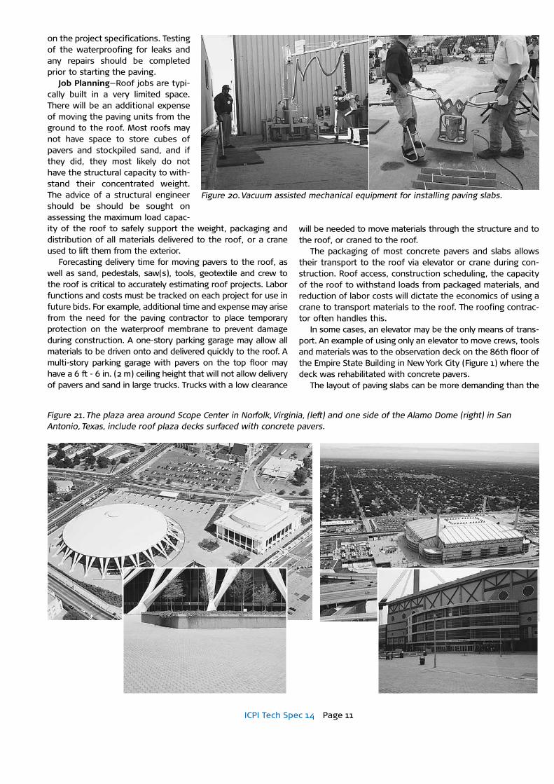
Figure 18. A mechanical screed used to level bedding sand on a roof parking deck project.
membrane will be exposed to continual standing water and ice that accelerates its deterioration and increases the potential for leaks. Likewise, paving units and bedding materials in con-stantly standing water subject to many freeze and thaw cycles will experience a decrease in their useful life.
Regardless of the deck substrate, it should be built with a minimum 2% slope to drain. This may be difficult to achieve with certain decks sloping toward area drains and some decks are built flat and then a topping applied to achieve slopes. The designers should take every opportunity to use deck systems that enable construction of a minimum 2% slope as some top-pings are not waterproof and flat roofs will eventually leak.
Slopes for pedestrians and vehicles —The maximum slope is constrained by the need for a comfortable walking surface and the maximum percentage is typically 8% (4.5°). For driving surfaces, the maximum recommended slope should not exceed 20% (11°) and ideally should not exceed 8% as such surfaces will often see pedestrian use. For slopes exceeding 4% with exposure to vehicles, consideration should be given to using bituminous-set rather than sand set systems.
Roof drains—Depending on the design, roofs are drained at their edges and/or from the interior with roof drains. When roofs decks are loaded with dead and live loads, they will deflect. Continual deflection over time results in deformation of the roof. This movement can make drain inlets or scuppers adjacent to columns or on frame lines at the perimeter of the highest points of the roof. Therefore, sufficient pitch to the roof that accounts for such deflections is essential to contin-ual drainage. In addition, the surface of the paving should be a minimum of 3/16 in. (5 mm) above the inlet of roof drains.
When sand or aggregate is used for bedding or fill, it is essential that holes be in the sides of drains to allow water to escape the bedding sand. The bottom of the holes should be at the same elevation as the top of the waterproof mem-brane. As previously noted, drains should be wrapped in geo-textile to prevent loss of bedding material through the drain holes.
Figure 15 illustrates ponding around a parking deck roof drain that didn’t have drain holes in its sides to drain subsur-face water. Figures 16 and 17 illustrate a possible drain solution with holes for a pedestrian roof and parking deck. For paving
slabs with pedestals, the slabs generally are located over roof drains, or are cut to fit around drains (see Figure 5). Bitumen-set assemblies require holes in the sides of the drains to remove water that may collect below the paving units. Bitumen and neoprene must not be allowed to clog roof drains or holes on their sides during installation.
Raising elevations—New and rehabilitated roofs may require fill material for raising the paved surface so it conforms to adjacent elevations. The deck surface receiving the fill material should slope a minimum of 2%. Fill materials are typically concrete, asphalt, or open-graded base. The struc-ture should be evaluated first by a structural engineer for its capability in taking the additional load. Lightweight concrete may be considered if there are load limitations. These fill materials are often placed over a water-proof membrane. Consideration should be given to using insulation and protec-tion board over the waterproof membrane. Attention in detail-ing and during construction should be given to how the fill materials will meet vents, skylights and other protrusions in the roof without damage to them, their flashing, or to their waterproofing. Open-graded bases will require geotextile under them to contain them. The fabric should cover all sides of the base.
Dense-graded aggregate base fill materials are not recom-mended since water can collect at the bottom of the base and soften it. Over time, this condition can increase the potential for deformation of the base under repeated vehicular wheel loads. In addition, aggregate base materials can shed fine particles that, over time, can clog geotextiles and drains. Concrete, asphalt, or open-graded bases are preferred as fill materials since they do not deform when continually exposed to water. In addition, they seldom shed particles into the roof drains so they present a much lower risk of clogged geotextile and drains.
Due to its high temperature at application, asphalt may not be compatible with some waterproof membranes, insulation, or protection board. All fill materials should be reviewed with the manufacturer for compatability with these components. Other important considerations are the minimum thickness to which the fill materials can be applied without cracking and deterioration from freeze-thaw cycles and salts. The design
and selection of fill materials should address movement from tempera-ture changes, vibration (if exposed to vehicles) and seismic activity.
Construction ConsiderationsLow slope roofs and waterproofing systems are generally installed by a specialty roofing subcontractor. A second subcontractor specializing in the installation of segmental pav-ing supplies and installs bedding materials, pedestals, pavers or slabs after the waterproofing is placed by the roofing contractor. Installation of protection board and/or drainage mat may be by the paving contrac-tor or roofing contractor depending
Figure 19. Mechanical equipment used to install concrete pavers on a roof deck.
ICPI Tech Spec 14 Page 11
Figure 21. The plaza area around Scope Center in Norfolk, Virginia, (left) and one side of the Alamo Dome (right) in San Antonio, Texas, include roof plaza decks surfaced with concrete pavers.
on the project specifications. Testing of the waterproofing for leaks and any repairs should be completed prior to starting the paving.
Job Planning—Roof jobs are typi-cally built in a very limited space. There will be an additional expense of moving the paving units from the ground to the roof. Most roofs may not have space to store cubes of pavers and stockpiled sand, and if they did, they most likely do not have the structural capacity to with-stand their concentrated weight. The advice of a structural engineer should be should be sought on assessing the maximum load capac-ity of the roof to safely support the weight, packaging and distribution of all materials delivered to the roof, or a crane used to lift them from the exterior.
Forecasting delivery time for moving pavers to the roof, as well as sand, pedestals, saw(s), tools, geotextile and crew to the roof is critical to accurately estimating roof projects. Labor functions and costs must be tracked on each project for use in future bids. For example, additional time and expense may arise from the need for the paving contractor to place temporary protection on the waterproof membrane to prevent damage during construction. A one-story parking garage may allow all materials to be driven onto and delivered quickly to the roof. A multi-story parking garage with pavers on the top floor may have a 6 ft - 6 in. (2 m) ceiling height that will not allow delivery of pavers and sand in large trucks. Trucks with a low clearance
will be needed to move materials through the structure and to the roof, or craned to the roof.
The packaging of most concrete pavers and slabs allows their transport to the roof via elevator or crane during con-struction. Roof access, construction scheduling, the capacity of the roof to withstand loads from packaged materials, and reduction of labor costs will dictate the economics of using a crane to transport materials to the roof. The roofing contrac-tor often handles this.
In some cases, an elevator may be the only means of trans-port. An example of using only an elevator to move crews, tools and materials was to the observation deck on the 86th floor of the Empire State Building in New York City (Figure 1) where the deck was rehabilitated with concrete pavers.
The layout of paving slabs can be more demanding than the
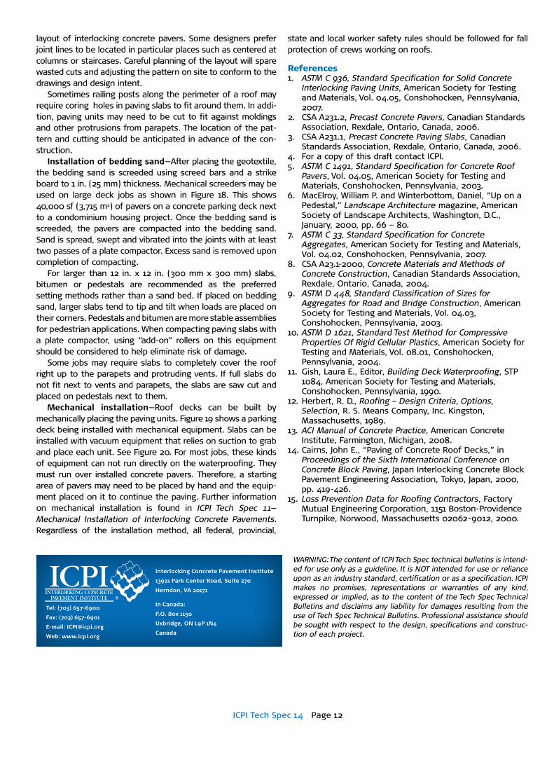
Figure 20. Vacuum assisted mechanical equipment for installing paving slabs.
ICPI Tech Spec 14 Page 12
WARNING: The content of ICPI Tech Spec technical bulletins is intend-ed for use only as a guideline. It is NOT intended for use or reliance upon as an industry standard, certification or as a specification. ICPI makes no promises, representations or warranties of any kind, expressed or implied, as to the content of the Tech Spec Technical Bulletins and disclaims any liability for damages resulting from the use of Tech Spec Technical Bulletins. Professional assistance should be sought with respect to the design, specifications and construc-tion of each project.
layout of interlocking concrete pavers. Some designers prefer joint lines to be located in particular places such as centered at columns or staircases. Careful planning of the layout will spare wasted cuts and adjusting the pattern on site to conform to the drawings and design intent.
Sometimes railing posts along the perimeter of a roof may require coring holes in paving slabs to fit around them. In addi-tion, paving units may need to be cut to fit against moldings and other protrusions from parapets. The location of the pat-tern and cutting should be anticipated in advance of the con-struction.
Installation of bedding sand—After placing the geotextile, the bedding sand is screeded using screed bars and a strike board to 1 in. (25 mm) thickness. Mechanical screeders may be used on large deck jobs as shown in Figure 18. This shows 40,000 sf (3,715 m2) of pavers on a concrete parking deck next to a condominium housing project. Once the bedding sand is screeded, the pavers are compacted into the bedding sand. Sand is spread, swept and vibrated into the joints with at least two passes of a plate compactor. Excess sand is removed upon completion of compacting.
For larger than 12 in. x 12 in. (300 mm x 300 mm) slabs, bitumen or pedestals are recommended as the preferred setting methods rather than a sand bed. If placed on bedding sand, larger slabs tend to tip and tilt when loads are placed on their corners. Pedestals and bitumen are more stable assemblies for pedestrian applications. When compacting paving slabs with a plate compactor, using “add-on” rollers on this equipment should be considered to help eliminate risk of damage.
Some jobs may require slabs to completely cover the roof right up to the parapets and protruding vents. If full slabs do not fit next to vents and parapets, the slabs are saw cut and placed on pedestals next to them.
Mechanical installation—Roof decks can be built by mechanically placing the paving units. Figure 19 shows a parking deck being installed with mechanical equipment. Slabs can be installed with vacuum equipment that relies on suction to grab and place each unit. See Figure 20. For most jobs, these kinds of equipment can not run directly on the waterproofing. They must run over installed concrete pavers. Therefore, a starting area of pavers may need to be placed by hand and the equip-ment placed on it to continue the paving. Further information on mechanical installation is found in ICPI Tech Spec 11—Mechanical Installation of Interlocking Concrete Pavements. Regardless of the installation method, all federal, provincial,
state and local worker safety rules should be followed for fall protection of crews working on roofs.
References1. ASTM C 936, Standard Specification for Solid Concrete
Interlocking Paving Units, American Society for Testing and Materials, Vol. 04.05, Conshohocken, Pennsylvania, 2007.
2. CSA A231.2, Precast Concrete Pavers, Canadian Standards Association, Rexdale, Ontario, Canada, 2006.
3. CSA A231.1, Precast Concrete Paving Slabs, Canadian Standards Association, Rexdale, Ontario, Canada, 2006.
4. For a copy of this draft contact ICPI.5. ASTM C 1491, Standard Specification for Concrete Roof
Pavers, Vol. 04.05, American Society for Testing and Materials, Conshohocken, Pennsylvania, 2003.
6. MacElroy, William P. and Winterbottom, Daniel, “Up on a Pedestal,” Landscape Architecture magazine, American Society of Landscape Architects, Washington, D.C., January, 2000, pp. 66 – 80.
7. ASTM C 33, Standard Specification for Concrete Aggregates, American Society for Testing and Materials, Vol. 04.02, Conshohocken, Pennsylvania, 2007.
8. CSA A23.1-2000, Concrete Materials and Methods of Concrete Construction, Canadian Standards Association, Rexdale, Ontario, Canada, 2004.
9. ASTM D 448, Standard Classification of Sizes for Aggregates for Road and Bridge Construction, American Society for Testing and Materials, Vol. 04.03, Conshohocken, Pennsylvania, 2003.
10. ASTM D 1621, Standard Test Method for Compressive Properties Of Rigid Cellular Plastics, American Society for Testing and Materials, Vol. 08.01, Conshohocken, Pennsylvania, 2004.
11. Gish, Laura E., Editor, Building Deck Waterproofing, STP 1084, American Society for Testing and Materials, Conshohocken, Pennsylvania, 1990.
12. Herbert, R. D., Roofing – Design Criteria, Options, Selection, R. S. Means Company, Inc. Kingston, Massachusetts, 1989.
13. ACI Manual of Concrete Practice, American Concrete Institute, Farmington, Michigan, 2008.
14. Cairns, John E., “Paving of Concrete Roof Decks,” in Proceedings of the Sixth International Conference on Concrete Block Paving, Japan Interlocking Concrete Block Pavement Engineering Association, Tokyo, Japan, 2000, pp. 419-426.
15. Loss Prevention Data for Roofing Contractors, Factory Mutual Engineering Corporation, 1151 Boston-Providence Turnpike, Norwood, Massachusetts 02062-9012, 2000.
Interlocking Concrete Pavement Institute
13921 Park Center Road, Suite 270
Herndon, VA 20171
In Canada:
P.O. Box 1150
Uxbridge, ON L9P 1N4
Canada
Tel: (703) 657-6900
Fax: (703) 657-6901
E-mail: [email protected]
Web: www.icpi.org