Embed Size (px)
Citation preview
1. Introduction
This document defines the technical requirements and design features for design, manufacture and testing of 6000 HP BG three phase IGBT based AC-AC Diesel Electric locomotive.
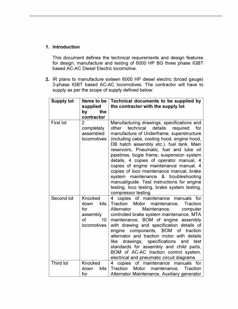
2. IR plans to manufacture sixteen 6000 HP diesel electric (broad gauge) 3-phase IGBT based AC-AC locomotives. The contractor will have to supply as per the scope of supply defined below:
Supply lot Items to be supplied by the contractor
Technical documents to be supplied by the contractor with the supply lot
First lot 2 completely assembled locomotives
Manufacturing drawings, specifications and other technical details required for manufacture of Underframe, superstructure (including cabs, cooling hood, engine hood, DB hatch assembly etc.), fuel tank, Main reservoirs, Pneumatic, fuel and lube oil pipelines, bogie frame, suspension system details, 4 copies of operator manual, 4 copies of engine maintenance manual, 4 copies of loco maintenance manual, brake system maintenance & troubleshooting manual/guide. Test instructions for engine testing, loco testing, brake system testing, compressor testing.
Second lot Knocked down kits for assembly of 10 locomotives
4 copies of maintenance manuals for Traction Motor maintenance, Traction Alternator Maintenance, computer controlled brake system maintenance, MTA maintenance, BOM of engine assembly with drawing and specification details of engine components, BOM of traction alternator and traction motor with details like drawings, specifications and test standards for assembly and child parts, BOM of AC-AC traction control system, electrical and pneumatic circuit diagrams
Third lot Knocked down kits for
4 copies of maintenance manuals for Traction Motor maintenance, Traction Alternator Maintenance, Auxiliary generator
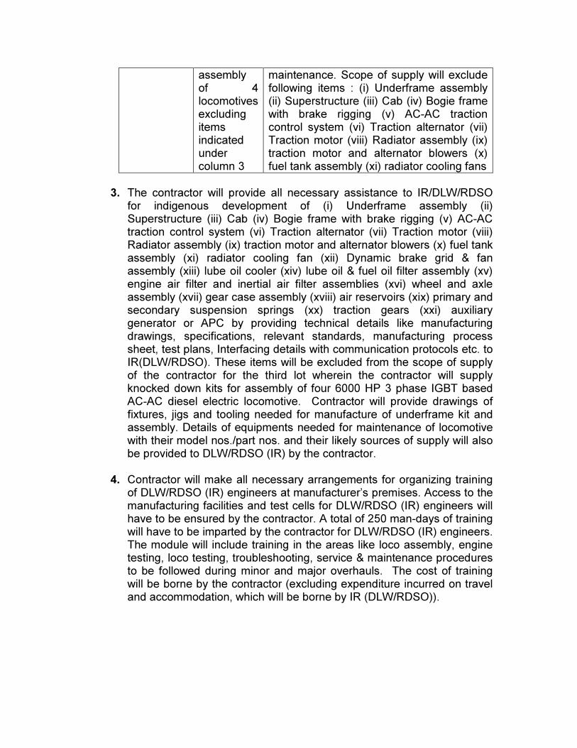
assembly of 4 locomotives excluding items indicated under column 3
maintenance. Scope of supply will exclude following items : (i) Underframe assembly (ii) Superstructure (iii) Cab (iv) Bogie frame with brake rigging (v) AC-AC traction control system (vi) Traction alternator (vii) Traction motor (viii) Radiator assembly (ix) traction motor and alternator blowers (x) fuel tank assembly (xi) radiator cooling fans
3. The contractor will provide all necessary assistance to IR/DLW/RDSO for indigenous development of (i) Underframe assembly (ii) Superstructure (iii) Cab (iv) Bogie frame with brake rigging (v) AC-AC traction control system (vi) Traction alternator (vii) Traction motor (viii) Radiator assembly (ix) traction motor and alternator blowers (x) fuel tank assembly (xi) radiator cooling fan (xii) Dynamic brake grid & fan assembly (xiii) lube oil cooler (xiv) lube oil & fuel oil filter assembly (xv) engine air filter and inertial air filter assemblies (xvi) wheel and axle assembly (xvii) gear case assembly (xviii) air reservoirs (xix) primary and secondary suspension springs (xx) traction gears (xxi) auxiliary generator or APC by providing technical details like manufacturing drawings, specifications, relevant standards, manufacturing process sheet, test plans, Interfacing details with communication protocols etc. to IR(DLW/RDSO). These items will be excluded from the scope of supply of the contractor for the third lot wherein the contractor will supply knocked down kits for assembly of four 6000 HP 3 phase IGBT based AC-AC diesel electric locomotive. Contractor will provide drawings of fixtures, jigs and tooling needed for manufacture of underframe kit and assembly. Details of equipments needed for maintenance of locomotive with their model nos./part nos. and their likely sources of supply will also be provided to DLW/RDSO (IR) by the contractor.
4. Contractor will make all necessary arrangements for organizing training of DLW/RDSO (IR) engineers at manufacturer’s premises. Access to the manufacturing facilities and test cells for DLW/RDSO (IR) engineers will have to be ensured by the contractor. A total of 250 man-days of training will have to be imparted by the contractor for DLW/RDSO (IR) engineers. The module will include training in the areas like loco assembly, engine testing, loco testing, troubleshooting, service & maintenance procedures to be followed during minor and major overhauls. The cost of training will be borne by the contractor (excluding expenditure incurred on travel and accommodation, which will be borne by IR (DLW/RDSO)).
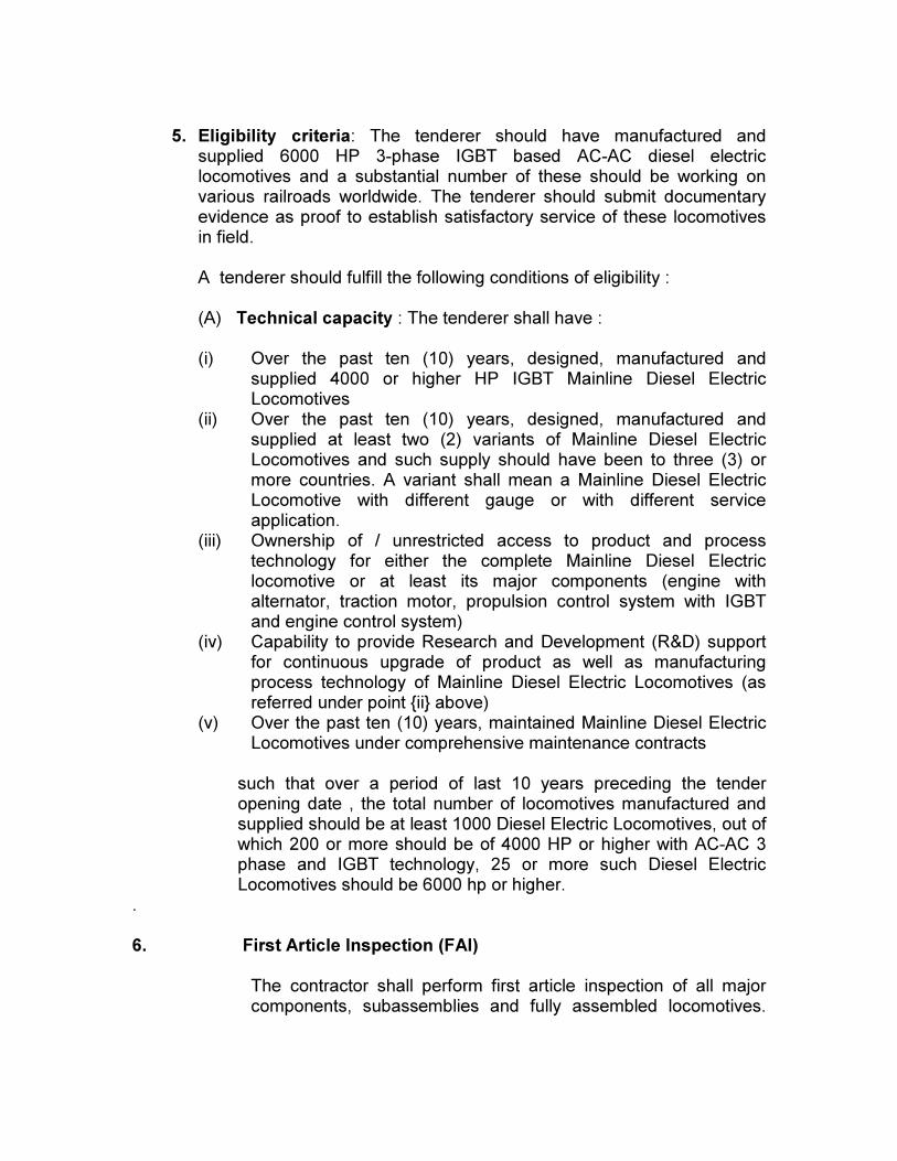
5. Eligibility criteria: The tenderer should have manufactured and supplied 6000 HP 3-phase IGBT based AC-AC diesel electric locomotives and a substantial number of these should be working on various railroads worldwide. The tenderer should submit documentary evidence as proof to establish satisfactory service of these locomotives in field.
A tenderer should fulfill the following conditions of eligibility : (A) Technical capacity : The tenderer shall have : (i) Over the past ten (10) years, designed, manufactured and
supplied 4000 or higher HP IGBT Mainline Diesel Electric Locomotives
(ii) Over the past ten (10) years, designed, manufactured and supplied at least two (2) variants of Mainline Diesel Electric Locomotives and such supply should have been to three (3) or more countries. A variant shall mean a Mainline Diesel Electric Locomotive with different gauge or with different service application.
(iii) Ownership of / unrestricted access to product and process technology for either the complete Mainline Diesel Electric locomotive or at least its major components (engine with alternator, traction motor, propulsion control system with IGBT and engine control system)
(iv) Capability to provide Research and Development (R&D) support for continuous upgrade of product as well as manufacturing process technology of Mainline Diesel Electric Locomotives (as referred under point {ii} above)
(v) Over the past ten (10) years, maintained Mainline Diesel Electric Locomotives under comprehensive maintenance contracts
such that over a period of last 10 years preceding the tender opening date , the total number of locomotives manufactured and supplied should be at least 1000 Diesel Electric Locomotives, out of which 200 or more should be of 4000 HP or higher with AC-AC 3 phase and IGBT technology, 25 or more such Diesel Electric Locomotives should be 6000 hp or higher.
. 6. First Article Inspection (FAI)
The contractor shall perform first article inspection of all major components, subassemblies and fully assembled locomotives.
The customer or its representatives shall be present to witness all FAIs.
6.1 Systems requiring FAI approval
A listing of proposed FAI items shall be included in the QA plan submitted to the customer for approval. This shall include as a minimum the following:
• Locomotive car body shell
• Control cab layout
• Prime mover
• Truck-frame
• Trucks-fully assembled
• Wheel and axle assemblies with Traction motors
• Cab seats
• Couplers and draft gear
• Electrical lockers
• All electrical panel
• Communication system
• All external and internal lighting systems and other components.
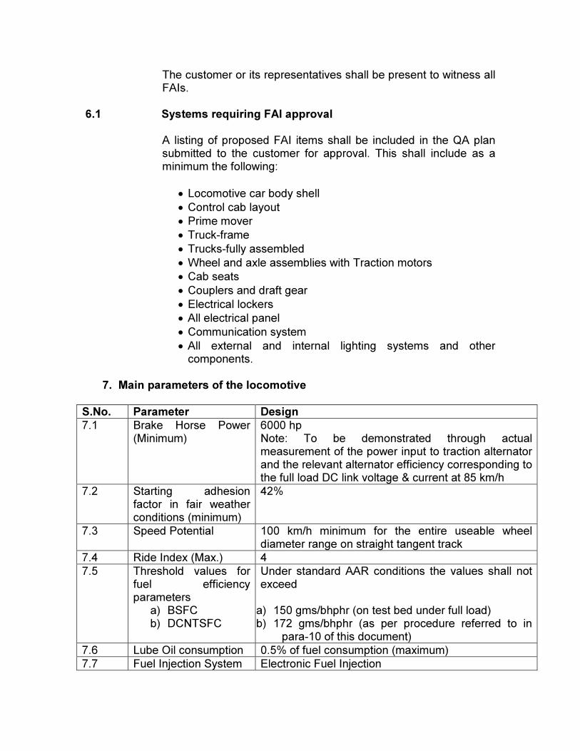
7. Main parameters of the locomotive
S.No. Parameter Design
7.1 Brake Horse Power (Minimum)
6000 hp Note: To be demonstrated through actual measurement of the power input to traction alternator and the relevant alternator efficiency corresponding to the full load DC link voltage & current at 85 km/h
7.2 Starting adhesion factor in fair weather conditions (minimum)
42%
7.3 Speed Potential 100 km/h minimum for the entire useable wheel diameter range on straight tangent track
7.4 Ride Index (Max.) 4
7.5 Threshold values for fuel efficiency parameters a) BSFC b) DCNTSFC
Under standard AAR conditions the values shall not exceed a) 150 gms/bhphr (on test bed under full load) b) 172 gms/bhphr (as per procedure referred to in
para-10 of this document)
7.6 Lube Oil consumption 0.5% of fuel consumption (maximum)
7.7 Fuel Injection System Electronic Fuel Injection
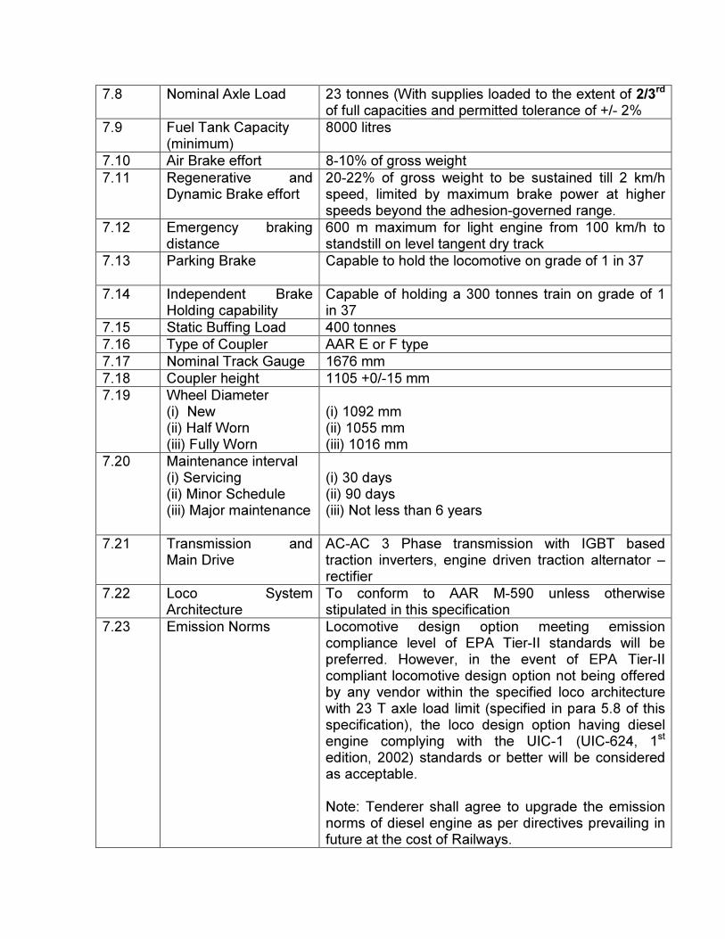
7.8 Nominal Axle Load 23 tonnes (With supplies loaded to the extent of 2/3rd of full capacities and permitted tolerance of +/- 2%
7.9 Fuel Tank Capacity (minimum)
8000 litres
7.10 Air Brake effort 8-10% of gross weight
7.11 Regenerative and Dynamic Brake effort
20-22% of gross weight to be sustained till 2 km/h speed, limited by maximum brake power at higher speeds beyond the adhesion-governed range.
7.12 Emergency braking distance
600 m maximum for light engine from 100 km/h to standstill on level tangent dry track
7.13 Parking Brake Capable to hold the locomotive on grade of 1 in 37
7.14 Independent Brake Holding capability
Capable of holding a 300 tonnes train on grade of 1 in 37
7.15 Static Buffing Load 400 tonnes
7.16 Type of Coupler AAR E or F type
7.17 Nominal Track Gauge 1676 mm
7.18 Coupler height 1105 +0/-15 mm
7.19 Wheel Diameter (i) New (ii) Half Worn (iii) Fully Worn
(i) 1092 mm (ii) 1055 mm (iii) 1016 mm
7.20 Maintenance interval (i) Servicing (ii) Minor Schedule (iii) Major maintenance
(i) 30 days (ii) 90 days (iii) Not less than 6 years
7.21 Transmission and Main Drive
AC-AC 3 Phase transmission with IGBT based traction inverters, engine driven traction alternator – rectifier
7.22 Loco System Architecture
To conform to AAR M-590 unless otherwise stipulated in this specification
7.23 Emission Norms Locomotive design option meeting emission compliance level of EPA Tier-II standards will be preferred. However, in the event of EPA Tier-II compliant locomotive design option not being offered by any vendor within the specified loco architecture with 23 T axle load limit (specified in para 5.8 of this specification), the loco design option having diesel engine complying with the UIC-1 (UIC-624, 1st edition, 2002) standards or better will be considered as acceptable. Note: Tenderer shall agree to upgrade the emission norms of diesel engine as per directives prevailing in future at the cost of Railways.
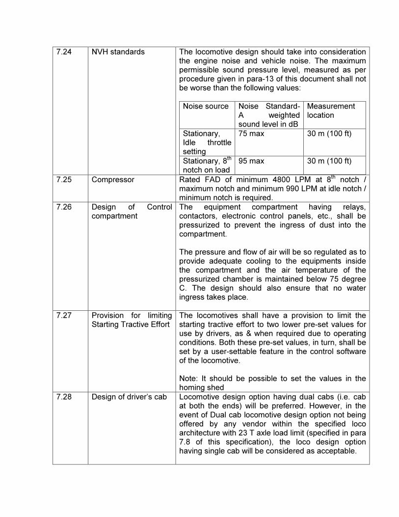
7.24 NVH standards The locomotive design should take into consideration the engine noise and vehicle noise. The maximum permissible sound pressure level, measured as per procedure given in para-13 of this document shall not be worse than the following values:
Noise source Noise Standard- A weighted sound level in dB
Measurement location
Stationary, Idle throttle setting
75 max 30 m (100 ft)
Stationary, 8th notch on load
95 max 30 m (100 ft)
7.25 Compressor Rated FAD of minimum 4800 LPM at 8th notch / maximum notch and minimum 990 LPM at idle notch / minimum notch is required.
7.26 Design of Control compartment
The equipment compartment having relays, contactors, electronic control panels, etc., shall be pressurized to prevent the ingress of dust into the compartment. The pressure and flow of air will be so regulated as to provide adequate cooling to the equipments inside the compartment and the air temperature of the pressurized chamber is maintained below 75 degree C. The design should also ensure that no water ingress takes place.
7.27 Provision for limiting Starting Tractive Effort
The locomotives shall have a provision to limit the starting tractive effort to two lower pre-set values for use by drivers, as & when required due to operating conditions. Both these pre-set values, in turn, shall be set by a user-settable feature in the control software of the locomotive. Note: It should be possible to set the values in the homing shed
7.28 Design of driver’s cab Locomotive design option having dual cabs (i.e. cab at both the ends) will be preferred. However, in the event of Dual cab locomotive design option not being offered by any vendor within the specified loco architecture with 23 T axle load limit (specified in para 7.8 of this specification), the loco design option having single cab will be considered as acceptable.
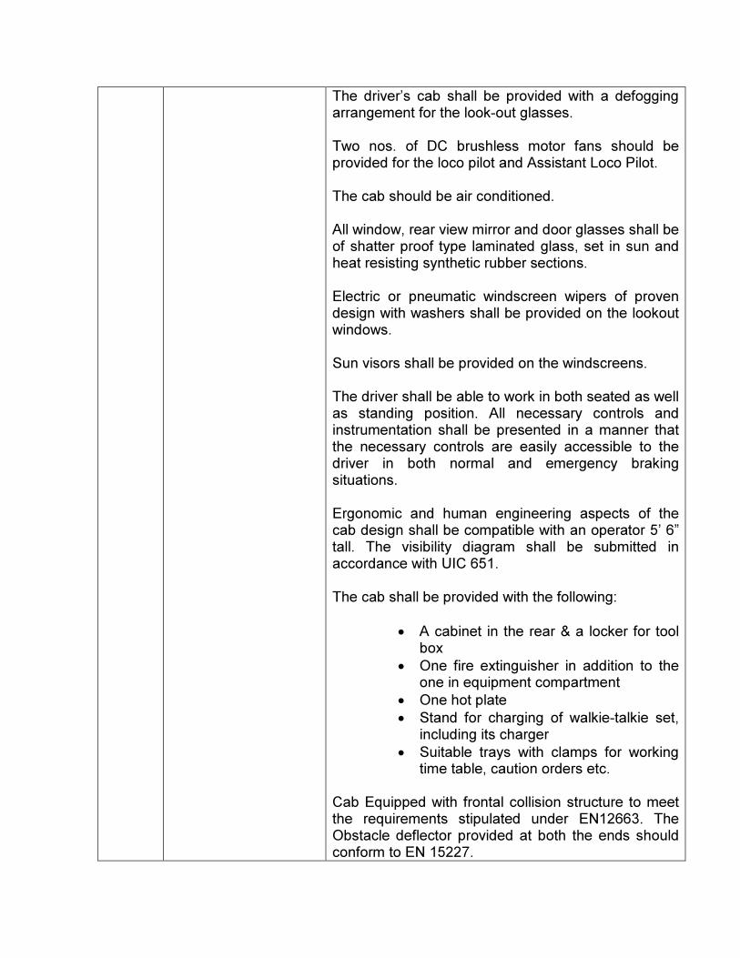
The driver’s cab shall be provided with a defogging arrangement for the look-out glasses. Two nos. of DC brushless motor fans should be provided for the loco pilot and Assistant Loco Pilot. The cab should be air conditioned. All window, rear view mirror and door glasses shall be of shatter proof type laminated glass, set in sun and heat resisting synthetic rubber sections. Electric or pneumatic windscreen wipers of proven design with washers shall be provided on the lookout windows. Sun visors shall be provided on the windscreens. The driver shall be able to work in both seated as well as standing position. All necessary controls and instrumentation shall be presented in a manner that the necessary controls are easily accessible to the driver in both normal and emergency braking situations. Ergonomic and human engineering aspects of the cab design shall be compatible with an operator 5’ 6” tall. The visibility diagram shall be submitted in accordance with UIC 651. The cab shall be provided with the following:
• A cabinet in the rear & a locker for tool box
• One fire extinguisher in addition to the one in equipment compartment
• One hot plate
• Stand for charging of walkie-talkie set, including its charger
• Suitable trays with clamps for working time table, caution orders etc.
Cab Equipped with frontal collision structure to meet the requirements stipulated under EN12663. The Obstacle deflector provided at both the ends should conform to EN 15227.
Noise level inside the cab should be less than 85 dB(A). Cab noise level should not exceed the maximum noise limits defined under FRA regulation no. 49 CFR Pt. 229.
Driver’s cab
The locomotive shall have full width cab(s). The cab(s) shall feature a clean, safe interior design with console-type control arrangement. The entire cab interior area, including console, panels, doors, windows, equipment, and etc. shall present an integrated environment consistent with modern design practices.
All required instrumentation is to be mounted in or adjacent to the desk console. Cab(s) shall be fully insulated throughout to achieve lowest possible cab interior noise level of less than 85dB. Layout shall maximize free floor space and shall be ergonomically designed.
Cab Doors
1. Cab shall have at least a minimum of two suitable doors to exterior.
2. Doors shall feature low and high external handles, recessed with sufficient handhold clearance and shall be free of sharp edges.
3. Doors shall be fitted with rugged, positive lockable latches:
i) Low level for access from Top of rail (TOR).
ii) High level for access from platform.
4. Door shall be lockable from the interior and exterior of the locomotive.
5. One door shall be provided for exiting the engine compartment close to the rear of the locomotive.
6. Cab area: one or more as required for reducing the engine room noise from the engine room, opening away from cab area and equipped with a panic release unlocking mechanism.
7. Door handles shall have adequate handhold clearance and positive latching mechanism and
shall be free of sharp edges.
8. Sealed against noise, fumes, dust and weather elements.
Seats
Two high-back style locomotive seats with adjustable lumbar support shall be provided in the cab. The seats shall have vertical, horizontal, reclining and rotating adjustments. A third seat shall be providing in cab.
Toilet Room
A low volume water, stainless steel, retention or waste treatment type toilet shall be provided. The toilet shall have a toilet paper dispenser, waste container and suitable handhold located on the wall adjacent to the toilet.
Heating, Ventilation and Air Conditioning (HVAC)
The heating ventilation and air conditioning unit shall be designed to provide a climate controlled environment for the locomotive.
Sun visors, clothes hooks, inspection and work report holders, waste container, cup holders, supply box, tissue box holder and tool box shall be provided in locomotive. Carbody Structure The locomotive carbody structure shall be equipped with a full –width streamlined cab employing a light-weight, high-strength monocoque structure. Carbody components and Attachments are handholds, horizontal grab handles, side steps/Exterior steps, grab handles, roof hatches, panel doors and floor openings, floors. Weathering Proofing Doors, windows and external hatches, Air intake and Exhaust, insulation etc.
7.29 Additional Features • The locomotive shall be equipped with a micro-processor based control system, including engine management system, with fault diagnostics, self load-box test (at full load) feature, adhesion and wheel slip control system & data logging
• The locomotive shall be equipped with VCD (Vigilance Control Device) & Event Recorder (with recording of approx. 12 parameters, sensed by the micro-processor or the Computer-controlled brake system otherwise). Event Recorder shall conform to FRA regulation no. 49-CFR-229.5
• It should be possible for IR maintenance staff to independently set the limits of main locomotive/engine parameters in the homing sheds through a user-settable interface built into the microprocessor control system, given that upto 8 such parameters would need to be set, depending upon the system offered. Typically, IR would need to have parameters like maximum loco speed, limiting of tractive effort to two pre-set values, limits for initiating corrective/protective action in case of Hot Engine, high leakage current, high or low battery charging current etc., as user settable but these parameters would be defined by mutual agreement between DLW/IR and the manufacturer
• Capability for remote data capture and GPS-enabled locating and communication facility for continuous monitoring by homing shed or locomotive controllers shall be provided, including one central server, data management & exception reports (to be offered separately as an optional)
• All the displays, whether Dial type for pressures, speed, TE, BE etc., or on/off type for equipment or indication alarms, shall be integrated electronically and displayed on LCD screen provided on the driver’s console. This display shall be suitable for day and night
viewing by the driver conforming to AAR-S-591
• Minimum 2 nos. of TFT display unit for each control desk is required to display gauge parameters, messages, speed etc.
• All accessories like radiator cooling fan(s), Traction Motor Blowers, Air compressor should be electrically driven
• All small motors should be AC type
• Locomotive shall be equipped with microprocessor controlled air brake system compatible with twin-pipe and single-pipe graduated release air brake system used on coaching and freight stock on IR, as specified in RDSO specification no. 02-ABR-02 (latest revision)
• Brake feed pipe end connections shall be as per RDSO drawing no. SK.DP-2861 and MU hoses shall be as per RDSO drawing no. WD081927-S-01 & SK.73547
• An automatic engine stop (AES) system with an allied auxiliary power unit to take care of battery charging, compressed air supply to brake system, cab lights & fans, head lights etc. shall be provided to save fuel while idling
• The loco should be provided with 4 marker lights (2 on each side). These should be provided with red & white LED. The operation of the marker light shall be through driver control switch.
• The loco should be provided with 2 nos. driver-operated yellow flasher lights, one for each direction of movement. These flasher lights shall get automatically activated in the event of train parting / emergency brake operation.
• Marker light should be LED type. Flasher light should be LED type and visibility of working flasher light shall not be less than 2 km in day light also. The flash rate should be 40
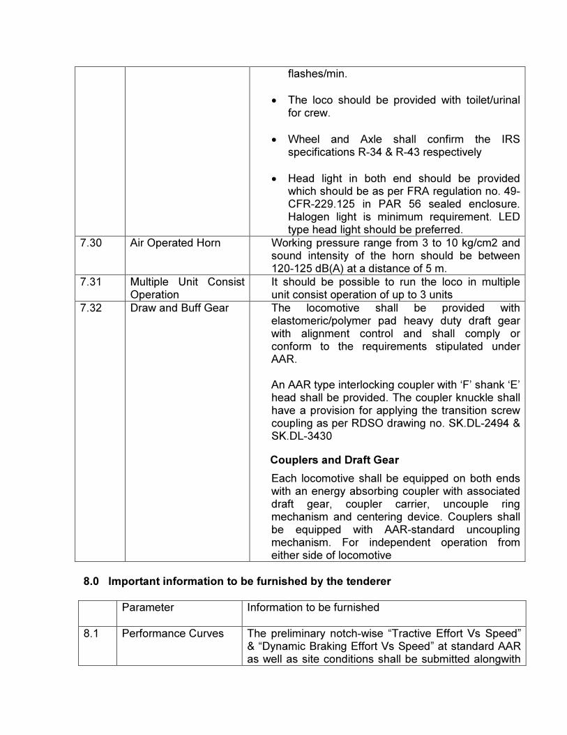
flashes/min.
• The loco should be provided with toilet/urinal for crew.
• Wheel and Axle shall confirm the IRS specifications R-34 & R-43 respectively
• Head light in both end should be provided which should be as per FRA regulation no. 49-CFR-229.125 in PAR 56 sealed enclosure. Halogen light is minimum requirement. LED type head light should be preferred.
7.30 Air Operated Horn Working pressure range from 3 to 10 kg/cm2 and sound intensity of the horn should be between 120-125 dB(A) at a distance of 5 m.
7.31 Multiple Unit Consist Operation
It should be possible to run the loco in multiple unit consist operation of up to 3 units
7.32 Draw and Buff Gear The locomotive shall be provided with elastomeric/polymer pad heavy duty draft gear with alignment control and shall comply or conform to the requirements stipulated under AAR. An AAR type interlocking coupler with ‘F’ shank ‘E’ head shall be provided. The coupler knuckle shall have a provision for applying the transition screw coupling as per RDSO drawing no. SK.DL-2494 & SK.DL-3430
Couplers and Draft Gear
Each locomotive shall be equipped on both ends with an energy absorbing coupler with associated draft gear, coupler carrier, uncouple ring mechanism and centering device. Couplers shall be equipped with AAR-standard uncoupling mechanism. For independent operation from either side of locomotive
8.0 Important information to be furnished by the tenderer
Parameter Information to be furnished
8.1 Performance Curves The preliminary notch-wise “Tractive Effort Vs Speed” & “Dynamic Braking Effort Vs Speed” at standard AAR as well as site conditions shall be submitted alongwith
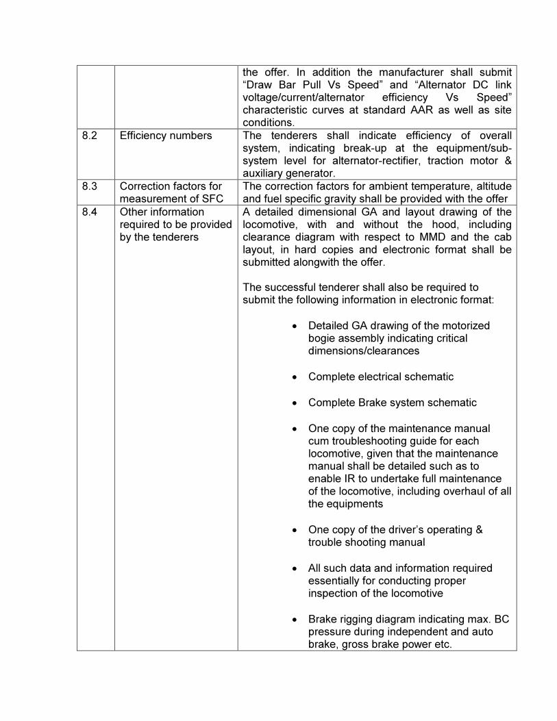
the offer. In addition the manufacturer shall submit “Draw Bar Pull Vs Speed” and “Alternator DC link voltage/current/alternator efficiency Vs Speed” characteristic curves at standard AAR as well as site conditions.
8.2 Efficiency numbers The tenderers shall indicate efficiency of overall system, indicating break-up at the equipment/sub-system level for alternator-rectifier, traction motor & auxiliary generator.
8.3 Correction factors for measurement of SFC
The correction factors for ambient temperature, altitude and fuel specific gravity shall be provided with the offer
8.4 Other information required to be provided by the tenderers
A detailed dimensional GA and layout drawing of the locomotive, with and without the hood, including clearance diagram with respect to MMD and the cab layout, in hard copies and electronic format shall be submitted alongwith the offer. The successful tenderer shall also be required to submit the following information in electronic format:
• Detailed GA drawing of the motorized bogie assembly indicating critical dimensions/clearances
• Complete electrical schematic
• Complete Brake system schematic
• One copy of the maintenance manual cum troubleshooting guide for each locomotive, given that the maintenance manual shall be detailed such as to enable IR to undertake full maintenance of the locomotive, including overhaul of all the equipments
• One copy of the driver’s operating & trouble shooting manual
• All such data and information required essentially for conducting proper inspection of the locomotive
• Brake rigging diagram indicating max. BC pressure during independent and auto brake, gross brake power etc.
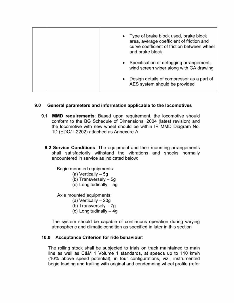
• Type of brake block used, brake block area, average coefficient of friction and curve coefficient of friction between wheel and brake block
• Specification of defogging arrangement, wind screen wiper along with GA drawing
• Design details of compressor as a part of AES system should be provided
9.0 General parameters and information applicable to the locomotives 9.1 MMD requirements: Based upon requirement, the locomotive should
conform to the BG Schedule of Dimensions, 2004 (latest revision) and the locomotive with new wheel should be within IR MMD Diagram No. 1D (EDO/T-2202) attached as Annexure-A
9.2 Service Conditions: The equipment and their mounting arrangements shall satisfactorily withstand the vibrations and shocks normally encountered in service as indicated below:
Bogie mounted equipments:
(a) Vertically – 5g (b) Transversely – 5g (c) Longitudinally – 5g
Axle mounted equipments:
(a) Vertically – 20g (b) Transversely – 7g (c) Longitudinally – 4g
The system should be capable of continuous operation during varying atmospheric and climatic condition as specified in later in this section
10.0 Acceptance Criterion for ride behaviour: The rolling stock shall be subjected to trials on track maintained to main line as well as C&M 1 Volume 1 standards, at speeds up to 110 km/h (10% above speed potential), in four configurations, viz., instrumented bogie leading and trailing with original and condemning wheel profile (refer
para 3). Following criteria will be used for clearing the stock for regular operations: a) The lateral / transverse forces lasting more than 2 meters shall not exceed 4.7 tonnes when measured at the wheel axle box level. Contractor shall also provide the suitable internationally accepted system to measure the lateral force during oscillation trials.
b) Evaluation shall also be done in terms of ride index which shall not be greater than 4. As international standard follows FFT method which gives approximately 20-25% lower RI value as compared to IR’s Average RI method. Average RI based evaluated RI is equivalent to approximately 3.2 FFT based RI.
c) A derailment Coefficient should be worked out in the form the ratio between the lateral force (Hy) and the Wheel Load (Q) continuously over a period of 1/20th second and the value of Hy/Q shall not exceed 1.
d) The value of acceleration recorded as near as possible to the bogie pivot, shall be limited to 0.3g both in vertical and lateral mode. A peak value upto 0.35g may be permitted, if the records do not indicate a resonant tendency in the region of the peak value
e) A general indication of stable running characteristic of the locomotives as evidenced by the movement of the bogie on straight and curved track and by the acceleration reading and instantaneous wheel load variation/spring deflections. The measurements shall be done by RDSO in accordance with report no. MT-334, issued April 2002.
11.0 Rating and Performance trials: These tests shall be done on prototype with new wheels, covering the following:
• Dynamometer car test to ascertain starting and rolling resistance of the locomotive and to prove “tractive effort-speed” characteristics and “dynamic braking effort-speed” characteristics.
• Adhesion test to prove adhesion capability
• Emergency Braking Distance trials For guidance, a sample test report enclosed as Annexure-7 to RDSO specification No. MP-0.08.00-74 (Revision-01), May 2014 can be referred.
Representatives of the manufacturer shall be associated during these tests
12.0 Field trials: Locomotive shall be subjected to field trials on IR for at least one month. The tenderer shall depute a team of engineers for commissioning, testing and field trials of the locomotive and its equipment in service. The tenderer’s representative shall associate in field trials jointly with DLW & RDSO.
13.0 Method for demonstrating NVH capabilities:
The manufacturer shall be required to demonstrate the NVH capabilities of the locomotive (on the prototype only), using the method given below:
(a) The microphone shall be calibrated to 94 dB(A) @1000 Hz , and Type 1 certified
(b) The microphone will be located as follows: - 100 Ft from the centerline of the track - 4” off the ground - A-side, centerline of locomotive - B-side, centerline of locomotive
(c) Measurement shall be A- weighted, slow response, 30 second average
(d) No precipitation (e) Wind speed < 15 mph (f) Locomotive shall be in standstill, connected to the external load box and developing full power. Load box will be located away from the locomotive.
(g) Test shall be at standard AAR conditions (h) Test location shall not have any structure, trees etc.close to the locomotive causing sound wave reflections.
(i) Air compressor shall be disabled.
14.0 Tenderer should refer para 5.12 and 5.13 of RDSO technical specification No. MP-0.08.00-74 (Revision-01), May 2014 for “Guiding test specifications for equipment” and “ Track conditions”.
15.0 Tenderer should refer para 5.11 and 5.10 of RDSO technical
specification No. MP-0.08.00-74 (Revision-01), May 2014 for “Climatic and environmental conditions ” and requirements with regard to “Compatibility with signal & telecommunication installations”.
16.0 Validation tests at manufacturer’s premises:
16.1 One prototype locomotive shall be tested for validation in
accordance with the AAR/UIC specification or the manufacturer’s internal test plan (which may be modified to suit Indian conditions), as the case may be. The test programme shall be submitted along with the offer.
16.2 Routine test of major electrical and mechanical equipments viz.
engine, turbocharger, alternator-rectifier, traction motor, Microprocessor controls and Computer controlled brake system, compressor on one prototype shall be carried out by the manufacturer at his own responsibility and cost in presence of the representatives of IR at the manufacturer’s premises, as per the test plan given by the manufacturer and approved by IR.
16.3 All major equipment and sub-assemblies, which are new and
not applied so far, shall invariably be type tested.
17.0 Fuel efficiency Guarantee benchmark:
There will be two benchmarks for fuel efficiency guarantee i.e. DCNTSFC and BSFC. The procedure defined in Annexure-5 of RDSO specification No. MP-0.08.00.74 (Revision-01), May 2014 will be followed for measurement of DCNTSFC and BSFC. The values of DCNTSFC and BSFC should in case be higher than the threshold values of DCNTSFC and BSFC specified in Para -7.5 of this document.
18.0 Locomotive Reliability Guarantee:
The reliability of the locomotives will be measured in terms of locomotive failures. The tenderer will have to guarantee locomotive reliability not to exceed 1 locomotive failure per loco per year, attributable to the contractor. Locomotive failures falling under the category of mismanagement by engine crew, bad workmanship during minor maintenance, bad fuel, failure on account of overdue maintenance by more than 72 hrs, failure during trail run / trip after heavy schedule when a trial message is issued in advance in consultation with purchaser’s authorized representative will not be considered on contractor’s account.
18.1 Reliability
Every complete locomotive, as well as each constituent component, assembly, subsystem and system element shall be designed in such a manner as to perform its function reliably in revenue service. Each locomotive under all system operating conditions shall operate with a failure rate not exceeding that defined in these technical specifications.
The Contractor shall prepare and submit at the Preliminary Design Review (PDR) for approval by the Customer a Reliability Program Plan which shall, as a minimum, contain the following:
• Program objectives
• Reliability program schedule
• Methodology to be used in reliability analyses
• Organization of personnel responsible for managing the reliability program
• Controls for activities of subcontractors and equipment suppliers to assure
compliance with reliability program methods and objectives.
• Preliminary reliability demonstration testing plans for verification of
compliance when calculations and analyses are inconclusive, or when past
performance records are incomplete or unavailable.
• Reliability demonstration program.
• Reliability demonstration procedures
• Reliability database in FileMaker Pro (current revision) or a database
agreed upon by the Contractor and Customer
18.2 Reliability objectives
The Contractor shall provide reliability objectives that identify the Mean Time between Failures (MTBF) and the Mean Time between Component Failure (MTBCF) performance levels to be met for its locomotive design and submitted to the Customer for approval.
A locomotive delay shall be defined as a locomotive-related failure causing a train in service to be:
• More than 15 minutes late at its destination terminal; or
• Canceled either at its originating point or en route.
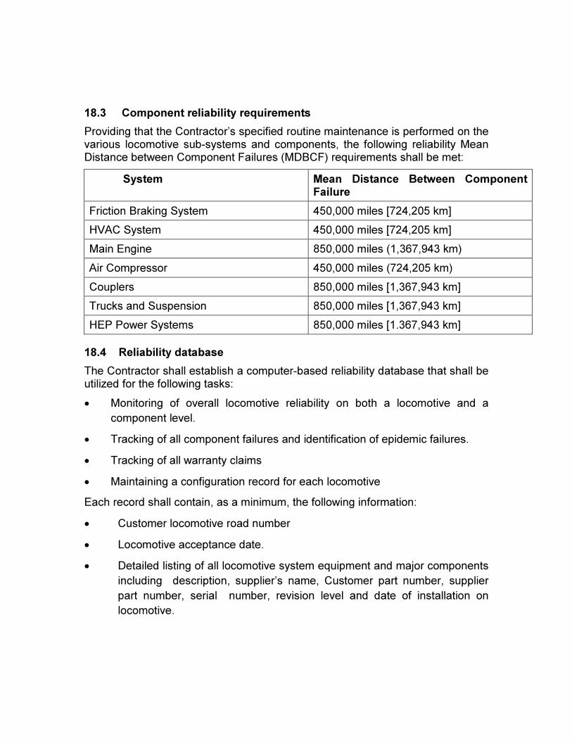
18.3 Component reliability requirements
Providing that the Contractor’s specified routine maintenance is performed on the various locomotive sub-systems and components, the following reliability Mean Distance between Component Failures (MDBCF) requirements shall be met:
System Mean Distance Between Component Failure
Friction Braking System 450,000 miles [724,205 km]
HVAC System 450,000 miles [724,205 km]
Main Engine 850,000 miles (1,367,943 km)
Air Compressor 450,000 miles (724,205 km)
Couplers 850,000 miles [1,367,943 km]
Trucks and Suspension 850,000 miles [1,367,943 km]
HEP Power Systems 850,000 miles [1.367,943 km]
18.4 Reliability database
The Contractor shall establish a computer-based reliability database that shall be utilized for the following tasks:
• Monitoring of overall locomotive reliability on both a locomotive and a
component level.
• Tracking of all component failures and identification of epidemic failures.
• Tracking of all warranty claims
• Maintaining a configuration record for each locomotive
Each record shall contain, as a minimum, the following information:
• Customer locomotive road number
• Locomotive acceptance date.
• Detailed listing of all locomotive system equipment and major components
including description, supplier’s name, Customer part number, supplier
part number, serial number, revision level and date of installation on
locomotive.
19.0 Maintainability
The locomotive shall be designed and built so as to minimize maintenance and repair time and overall costs over the locomotive life. The following shall be considered good practice in designing for maintainability and shall be utilized in the locomotive design:
• All systems and components serviced as part of periodic preventive
maintenance shall be readily accessible for service and inspection.
• Relative accessibility of components, measured in time to gain access,
shall be inversely proportional to frequency of maintenance and repair of
the components. (Items requiring more frequent maintenance shall be
easier to access).
• Assemblies and components that are physically interchangeable shall be
functionally interchangeable.
• Modular or plug-in assemblies and components that are not functionally
interchangeable shall not be physically interchangeable.
• All test points, fault indicators, modules, wire terminations, piping, tubes,
wires, etc., shall be identified by name plates, color coding, number coding
or other means to assist the maintenance personnel.
• Component placements in equipment cabinets, enclosures or confined
places shall give the most accessible positions to those items requiring the
most frequent maintenance or adjustment.
• Access shall be provided, to the greatest extent possible, to structural
components to allow inspection for cracks and corrosion.
• Major components shall be designed for ease of removal. Handles and
lifting eyes shall be provided as applicable..
• Requirements for special tools and fixtures shall be minimized.
The objectives of the maintainability program, including corrective and
preventive maintenance, shall provide for:
• Maximization of locomotive availability
• Minimization of maintenance costs, including cleaning
• Minimization of locomotive down time.
• Minimization of special and high skill levels for maintenance
• Minimization of special tools and fixtures