Embed Size (px)
Citation preview
TECH SHEET - DO NOT DISCARD PAGE 1
FOR SERVICE TECHNICIAN'S USE ONLY PART NO. 8301758 REV. A
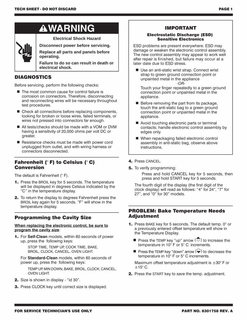
Disconnect power before servicing.
Replace all parts and panels beforeoperating.
Failure to do so can result in death orelectrical shock.
Electrical Shock Hazard
IMPORTANTElectrostatic Discharge (ESD)
Sensitive Electronics
ESD problems are present everywhere. ESD maydamage or weaken the electronic control assembly.The new control assembly may appear to work wellafter repair is finished, but failure may occur at alater date due to ESD stress.
Use an anti-static wrist strap. Connect wriststrap to green ground connection point orunpainted metal in the appliance
-OR-Touch your finger repeatedly to a green groundconnection point or unpainted metal in theappliance.
Before removing the part from its package,touch the anti-static bag to a green groundconnection point or unpainted metal in theappliance.
Avoid touching electronic parts or terminalcontacts; handle electronic control assembly byedges only.
When repackaging failed electronic controlassembly in anti-static bag, observe aboveinstructions.
DIAGNOSTICS
Before servicing, perform the following checks:
The most common cause for control failure iscorrosion on connectors. Therefore, disconnectingand reconnecting wires will be necessary throughouttest procedures.
Check all connections before replacing components,looking for broken or loose wires, failed terminals, orwires not pressed into connectors far enough.
All tests/checks should be made with a VOM or DVMhaving a sensitivity of 20,000 ohms per volt DC orgreater.
Resistance checks must be made with power cordunplugged from outlet, and with wiring harness orconnectors disconnected.
Fahrenheit (° F) to Celsius (° C)Conversion
The default is Fahrenheit (° F).
1. Press the BROIL key for 5 seconds. The temperaturewill be displayed in degrees Celsius indicated by the“C” in the temperature display.
2. To return the display to degrees Fahrenheit press theBROIL key again for 5 seconds. “F” will show in thetemperature display.
Programming the Cavity Size
When replacing the electronic control, be sure toprogram the cavity size:
1. For Self-Clean models, within 60 seconds of powerup, press the following keys:
STOP TIME, TEMP UP, COOK TIME, BAKE,BROIL, CLOCK, CANCEL, OVEN LIGHT.
For Standard-Clean models, within 60 seconds ofpower up, press the following keys:
TEMP UP, MIN DOWN, BAKE, BROIL, CLOCK, CANCEL,OVEN LIGHT.
2. Size is shown in display - “id 30”.
3. Press CLOCK key until correct size is displayed.
4. Press CANCEL.
5. To verify programming:Press and hold CANCEL key for 5 seconds, thenpress and hold START key for 5 seconds.
The fourth digit of the display (the first digit of theclock display) will read as follows: “4” for 24”, “7” for27”, and “0” for 30” models.
PROBLEM: Bake Temperature NeedsAdjustment
1. Press BAKE key for 5 seconds. The default temp. 0° ora previously entered offset temperature will show inthe Temperature Display.
Press the TEMP key “up” arrow ( ) to increase thetemperature in 10° F or 5° C increments.
Press the TEMP key “down” arrow ( ) to decrease thetemperature in 10° F or 5° C increments.
Maximum offset temperature adjustment is ±30° F or±15° C.
2. Press the START key to save the temp. adjustment.

TECH SHEET - DO NOT DISCARD PAGE 2
FOR SERVICE TECHNICIAN'S USE ONLY PART NO. 8301758 REV. A
FAULTCODE
ERRORCODE
CODEEXPLANATION RECOMMENDED REPAIR PROCEDURE
F0 Default F code - no failureWill only be displayed if user presses and holds CANCEL key for 5seconds and there are no pre-existing faults. Press CANCEL to cleardisplay.
F1 All ECodes Electronic control malfunction 1.Disconnect power or unplug oven.
2.Replace control.
F2
E0 Key held down too long, orkey is shorted 1.Disconnect power or unplug oven.
2.Check keypad connector for firm connection.3.Press CANCEL. If error code returns after 60 sec., replace keypad.4.Replace control.
E1 Keypad keytail not connected
E5E6 CANCEL key drive line open
F3
E0 Temperature sensor openedR=2875Ω (by spec)
1.Disconnect power or unplug oven.2.Check sensor connection.3.Measure sensor resistance (1080 Ω at 70° F [21° C]. Add 2 Ω per
degree F).4.If resistance is not valid, replace sensor.5.If sensor resistance and connections are good, then check for
welded-closed relays on the control.
E1 Temperature sensor shortedR=825Ω (by spec)
E2Oven temp too high - over575° F (301° C) in COOKmode
E3Oven temp too high - over950° F (510° C) in CLEANmode
F5
E0
Door is open, but latch islocked (condition exists whendoor switch is open indicatingan open door, and latchswitch is closed indicating alocked door).
1.Disconnect power or unplug oven.2.Check the latch assembly: latch arm pivot joint, arm/motor
connection, plunger and hook springs.3.Check the Latch Motor:
- Check for firm electrical connections.- Disconnect the two wires from the motor and measure the
resistance of the motor. The resistance should be approximately2450 Ω. If the motor is open (∞Ω) or shorted (0Ω), it should bereplaced.
4.Check the Latch Switch. Disconnect it and use a continuity tester:- Door latched = switch closed, continuity should read 0Ω.- Door unlatched = switch open, continuity should read ∞Ω.
5.Check Door Open/Closed Switch. Disconnect it and use acontinuity tester:- Door open = switch open, continuity should read ∞Ω.- Door closed = switch closed, continuity should read 0Ω.
6.Check power and element connections.
E1 Self-clean latch will not lock orwill not unlock.
NOTES:
Always disconnect power before touching internal parts of the oven!
Upon replacement, immediately return old electronic oven controlusing the mailing label supplied with each new control.
FAILURE/ERRORDISPLAY CODES
TECH SHEET - DO NOT DISCARD PAGE 3
FOR SERVICE TECHNICIAN'S USE ONLY PART NO. 8301758 REV. A
THERMALFUSE/T.O.D.
GROUND (CHASSIS)
PLUG WITH FEMALECONNECTOR
RECEPTACLE WITHMALE CONNECTOR
LIGHT
AC DRIVEMOTOR
RELAYCONTACTS
HEATINGELEMENT
SOLENOID
ENCLOSEDTHERMISTOR
OPERATEDBY DOOR
RELAY COIL
M
t°
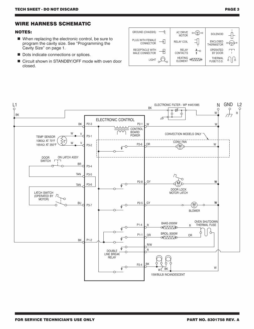
WIRE HARNESS SCHEMATIC
NOTES:
When replacing the electronic control, be sure toprogram the cavity size. See “Programming theCavity Size” on page 1.
Dots indicate connections or splices.
Circuit shown in STANDBY/OFF mode with oven doorclosed.
TECH SHEET - DO NOT DISCARD PAGE 4
FOR SERVICE TECHNICIAN'S USE ONLY PART NO. 8301758 REV. A
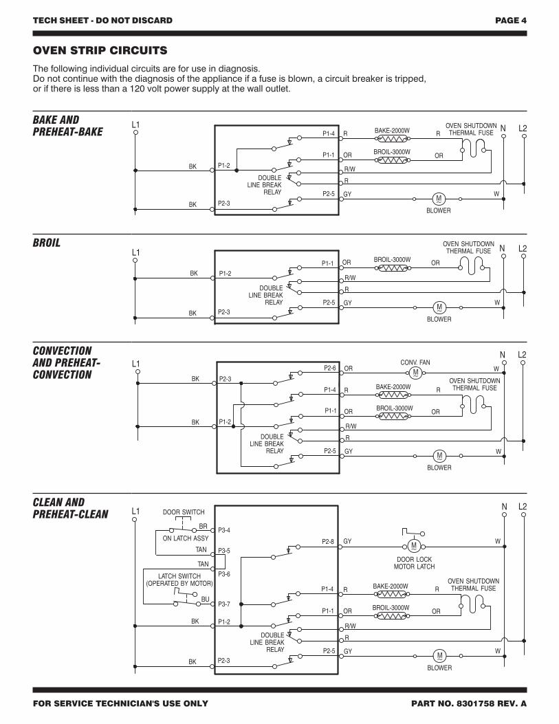
OVEN STRIP CIRCUITS
The following individual circuits are for use in diagnosis.Do not continue with the diagnosis of the appliance if a fuse is blown, a circuit breaker is tripped,or if there is less than a 120 volt power supply at the wall outlet.
DOUBLELINE BREAK
RELAY
BROIL-3000WORL1 L2N
P1-1 OR
BK
GY
BLOWER
P2-5
R
R/W
W
P1-2
BK P2-3
OVEN SHUTDOWNTHERMAL FUSE
BROIL
DOUBLELINE BREAK
RELAY
BAKE-2000W
BROIL-3000W
R
OR
CONV. FANORL1
L2N
BK
BK
P2-6
P1-4
P1-1
W
OR
R
GY
BLOWER
P2-5
R
R/W
W
P1-2
P2-3 OVEN SHUTDOWNTHERMAL FUSE
CONVECTIONAND PREHEAT-CONVECTION
DOUBLELINE BREAK
RELAY
OR
BAKE-2000W
BROIL-3000W
R
OR
L1 L2
GY
N
BLOWER
P1-4
P1-1
P2-5
R
R/W
W
BK P1-2
BK P2-3
ROVEN SHUTDOWN
THERMAL FUSE
BAKE ANDPREHEAT-BAKE
P2-8 GY
DOOR LOCKMOTOR LATCH
DOUBLELINE BREAK
RELAY
BAKE-2000W
BROIL-3000W
R
OR
L1 L2N
BK
P1-4
P1-1
P1-2
OR
R
GY
BLOWER
P2-5
R
R/W
W
BK P2-3
OVEN SHUTDOWNTHERMAL FUSE
W
DOOR SWITCH
ON LATCH ASSY
BR
BU
LATCH SWITCH(OPERATED BY MOTOR)
TAN
TAN
P3-4
P3-5
P3-6
P3-7
CLEAN ANDPREHEAT-CLEAN
TECH SHEET - DO NOT DISCARD PAGE 5
FOR SERVICE TECHNICIAN'S USE ONLY PART NO. 8301758 REV. A
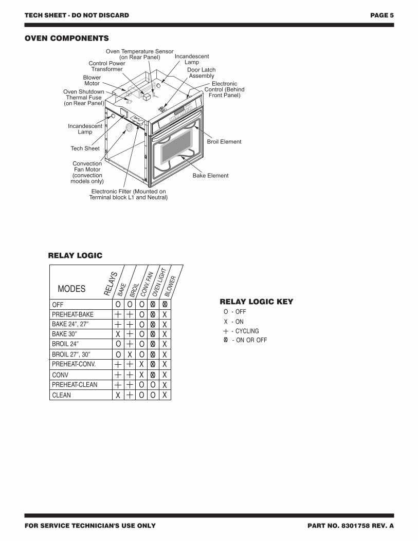
OVEN COMPONENTS
RELAY LOGIC KEY
RELAY LOGIC
TECH SHEET - DO NOT DISCARD PAGE 6
FOR SERVICE TECHNICIAN'S USE ONLY PART NO. 8301758 REV. A
4,102,322 4,364,589 4,467,184
OTHER PATENTS PENDING
MANUFACTURED UNDER ONE OR MORE OF THEFOLLOWING UNITED STATES PATENTS:
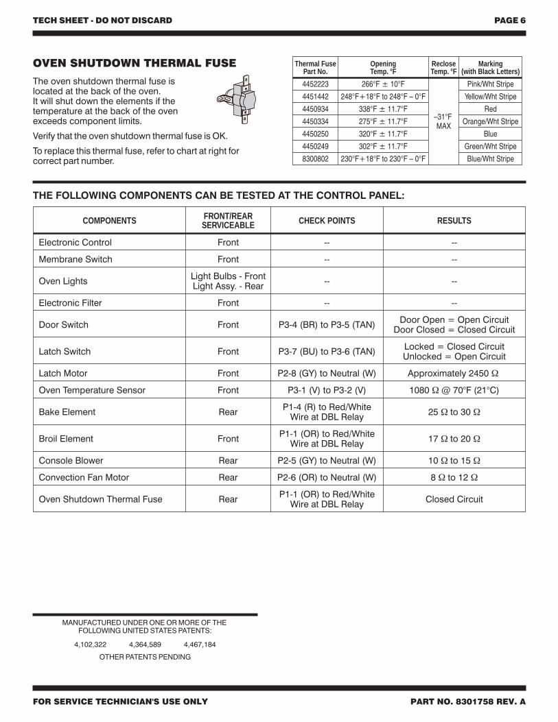
THE FOLLOWING COMPONENTS CAN BE TESTED AT THE CONTROL PANEL:
OVEN SHUTDOWN THERMAL FUSE
The oven shutdown thermal fuse islocated at the back of the oven.It will shut down the elements if thetemperature at the back of the ovenexceeds component limits.
Verify that the oven shutdown thermal fuse is OK.
To replace this thermal fuse, refer to chart at right forcorrect part number.
Thermal FusePart No.
OpeningTemp. °F
RecloseTemp. °F
Marking(with Black Letters)
4452223 266°F ± 10°F
–31°FMAX
Pink/Wht Stripe
4451442 248°F+18°F to 248°F – 0°F Yellow/Wht Stripe
4450934 338°F ± 11.7°F Red
4450334 275°F ± 11.7°F Orange/Wht Stripe
4450250 320°F ± 11.7°F Blue
4450249 302°F ± 11.7°F Green/Wht Stripe
8300802 230°F+18°F to 230°F – 0°F Blue/Wht Stripe
COMPONENTS FRONT/REARSERVICEABLE CHECK POINTS RESULTS
Electronic Control Front -- --
Membrane Switch Front -- --
Oven Lights Light Bulbs - FrontLight Assy. - Rear -- --
Electronic Filter Front -- --
Door Switch Front P3-4 (BR) to P3-5 (TAN) Door Open = Open CircuitDoor Closed = Closed Circuit
Latch Switch Front P3-7 (BU) to P3-6 (TAN) Locked = Closed CircuitUnlocked = Open Circuit
Latch Motor Front P2-8 (GY) to Neutral (W) Approximately 2450 Ω
Oven Temperature Sensor Front P3-1 (V) to P3-2 (V) 1080 Ω @ 70°F (21°C)
Bake Element Rear P1-4 (R) to Red/WhiteWire at DBL Relay 25 Ω to 30 Ω
Broil Element Front P1-1 (OR) to Red/WhiteWire at DBL Relay 17 Ω to 20 Ω
Console Blower Rear P2-5 (GY) to Neutral (W) 10 Ω to 15 Ω
Convection Fan Motor Rear P2-6 (OR) to Neutral (W) 8 Ω to 12 Ω
Oven Shutdown Thermal Fuse Rear P1-1 (OR) to Red/WhiteWire at DBL Relay Closed Circuit
FICHE TECHNIQUE - NE PAS JETER PAGE 1
À L’USAGE DU TECHNICIEN SEULEMENT PIÈCE No 8301758 RÉV. A
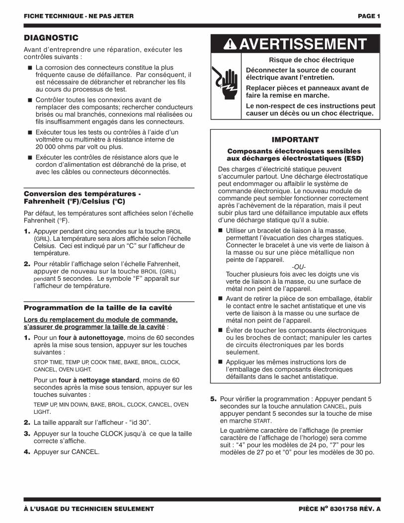
Déconnecter la source de courantélectrique avant l’entretien.
Replacer pièces et panneaux avant defaire la remise en marche.
Le non-respect de ces instructions peutcauser un décès ou un choc électrique.
Risque de choc électrique
IMPORTANT
Composants électroniques sensiblesaux décharges électrostatiques (ESD)
Des charges d’électricité statique peuvents’accumuler partout. Une décharge électrostatiquepeut endommager ou affaiblir le système decommande électronique. Le nouveau module decommande peut sembler fonctionner correctementaprès l’achèvement de la réparation, mais il peutsubir plus tard une défaillance imputable aux effetsd’une décharge statique qu’il a subie.
Utiliser un bracelet de liaison à la masse,permettant l’évacuation des charges statiques.Connecter le bracelet à une vis verte de liaison àla masse ou sur une pièce métallique nonpeinte de l’appareil.
-OU-Toucher plusieurs fois avec les doigts une visverte de liaison à la masse, ou une surface demétal non peint de l’appareil.
Avant de retirer la pièce de son emballage, établirle contact entre le sachet antistatique et une visverte de liaison à la masse ou une surface demétal non peint de l’appareil.
Éviter de toucher les composants électroniquesou les broches de contact; manipuler les cartesde circuits électroniques par les bordsseulement.
Appliquer les mêmes instructions lors del’emballage des composants électroniquesdéfaillants dans le sachet antistatique.
DIAGNOSTICAvant d’entreprendre une réparation, exécuter lescontrôles suivants :
La corrosion des connecteurs constitue la plusfréquente cause de défaillance. Par conséquent, ilest nécessaire de débrancher et rebrancher les filsau cours du processus de test.
Contrôler toutes les connexions avant deremplacer des composants; rechercher conducteursbrisés ou mal branchés, connexions mal réalisées oufils insuffisamment engagés dans les connecteurs.
Exécuter tous les tests ou contrôles à l’aide d’unvoltmètre ou multimètre à résistance interne de20 000 ohms par volt ou plus.
Exécuter les contrôles de résistance alors que lecordon d’alimentation est débranché de la prise, etavec les câbles ou connecteurs déconnectés.
Conversion des températures -Fahrenheit (°F)/Celsius (°C)
Par défaut, les températures sont affichées selon l’échelleFahrenheit (°F).
1. Appuyer pendant cinq secondes sur la touche BROIL(GRIL). La température sera alors affichée selon l’échelleCelsius. Ceci est indiqué par un “C” sur l’afficheur detempérature.
2. Pour rétablir l’affichage selon l’échelle Fahrenheit,appuyer de nouveau sur la touche BROIL (GRIL)pendant 5 secondes. Le symbole “F” apparaît surl’afficheur de température.
Programmation de la taille de la cavité
Lors du remplacement du module de commande,s’assurer de programmer la taille de la cavité :
1. Pour un four à autonettoyage, moins de 60 secondesaprès la mise sous tension, appuyer sur les touchessuivantes :STOP TIME, TEMP UP, COOK TIME, BAKE, BROIL, CLOCK,CANCEL, OVEN LIGHT.
Pour un four à nettoyage standard, moins de 60secondes après la mise sous tension, appuyer sur lestouches suivantes :TEMP UP, MIN DOWN, BAKE, BROIL, CLOCK, CANCEL, OVENLIGHT.
2. La taille apparaît sur l’afficheur - “id 30”.
3. Appuyer sur la touche CLOCK jusqu’à ce que la taillecorrecte s’affiche.
4. Appuyer sur CANCEL.
5. Pour vérifier la programmation : Appuyer pendant 5secondes sur la touche annulation CANCEL, puisappuyer pendant 5 secondes sur la touche de miseen marche START.Le quatrième caractère de l’affichage (le premiercaractère de l’affichage de l’horloge) sera commesuit : “4” pour les modèles de 24 po, “7” pour lesmodèles de 27 po et “0” pour les modèles de 30 po.
FICHE TECHNIQUE - NE PAS JETER PAGE 2
À L’USAGE DU TECHNICIEN SEULEMENT PIÈCE No 8301758 RÉV. A
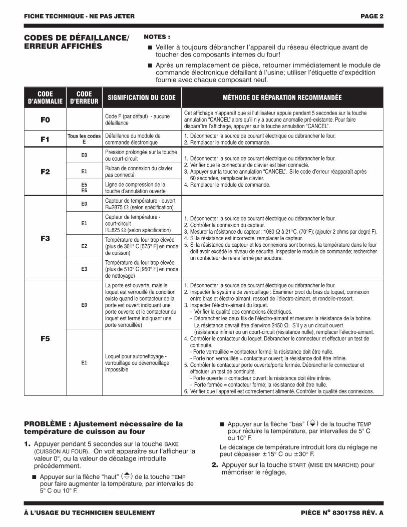
CODED’ANOMALIE
CODED’ERREUR SIGNIFICATION DU CODE MÉTHODE DE RÉPARATION RECOMMANDÉE
F0 Code F (par défaut) - aucunedéfaillance
Cet affichage n’apparaît que si l’utilisateur appuie pendant 5 secondes sur la toucheannulation “CANCEL” alors qu’il n’y a aucune anomalie pré-existante. Pour fairedisparaître l’affichage, appuyer sur la touche annulation “CANCEL”.
F1 Tous les codesE
Défaillance du module decommande électronique
1. Déconnecter la source de courant électrique ou débrancher le four.2. Remplacer le module de commande.
F2
E0 Pression prolongée sur la toucheou court-circuit 1. Déconnecter la source de courant électrique ou débrancher le four.
2. Vérifier que le connecteur de clavier est bien connecté.3. Appuyer sur la touche annulation “CANCEL”. Si le code d’erreur réapparaît après
60 secondes, remplacer le clavier.4. Remplacer le module de commande.
E1 Ruban de connexion du clavierpas connecté
E5E6
Ligne de compression de latouche d’annulation ouverte
F3
E0 Capteur de température - ouvertR=2875 Ω (selon spécification)
1. Déconnecter la source de courant électrique ou débrancher le four.2. Contrôler la connexion du capteur.3. Mesurer la résistance du capteur : 1080 Ω à 21°C, (70°F); (ajouter 2 ohms par degré F).4. Si la résistance est incorrecte, remplacer le capteur.5. Si la résistance du capteur et les connexions sont bonnes, la température dans le four
doit avoir excédé le niveau de sécurité. Inspecter le module de commande; rechercherun contacteur de relais fermé par soudure.
E1Capteur de température -court-circuitR=825 Ω (selon spécification)
E2Température du four trop élevée(plus de 301° C [575° F] en modede cuisson)
E3Température du four trop élevée(plus de 510° C [950° F] en modede nettoyage)
F5
E0
La porte est ouverte, mais leloquet est verrouillé (la conditionexiste quand le contacteur de laporte est ouvert indiquant uneporte ouverte et le contacteur duloquet est fermé indiquant uneporte verrouillée)
1. Déconnecter la source de courant électrique ou débrancher le four.2. Inspecter le système de verrouillage : Examiner pivot du bras du loquet, connexion
entre bras et électro-aimant, ressort de l’électro-aimant, et rondelle-ressort.3. Inspecter l’électro-aimant du loquet.
- Vérifier la qualité des connexions électriques.- Débrancher les deux fils de l’électro-aimant et mesurer la résistance de la bobine.
La résistance devrait être d’environ 2450 Ω. S’il y a un circuit ouvert(résistance infinie) ou un court-circuit (résistance nulle), remplacer l’électro-aimant.
4. Contrôler le contacteur du loquet. Débrancher le connecteur et effectuer un test decontinuité.- Porte verrouillée = contacteur fermé; la résistance doit être nulle.- Porte non verrouillée = contacteur ouvert; la résistance doit être infinie.
5. Contrôler le contacteur porte ouverte/porte fermée. Débrancher le connecteur eteffectuer un test de continuité.- Porte ouverte = contacteur ouvert; la résistance doit être infinie.- Porte fermée = contacteur fermé; la résistance doit être nulle.
6. Vérifier que l’appareil est correctement alimenté. Contrôler la qualité des connexions.
E1Loquet pour autonettoyage -verrouillage ou déverrouillageimpossible
CODES DE DÉFAILLANCE/ERREUR AFFICHÉS
NOTES :
Veiller à toujours débrancher l’appareil du réseau électrique avant detoucher des composants internes du four!
Après un remplacement de pièce, retourner immédiatement le module decommande électronique défaillant à l’usine; utiliser l’étiquette d’expéditionfournie avec chaque composant neuf.
PROBLÈME : Ajustement nécessaire de latempérature de cuisson au four
1. Appuyer pendant 5 secondes sur la touche BAKE(CUISSON AU FOUR). On voit apparaître sur l’afficheur lavaleur 0°, ou la valeur de décalage introduiteprécédemment.
Appuyer sur la flèche “haut” ( ) de la touche TEMPpour faire augmenter la température, par intervalles de5° C ou 10° F.
Appuyer sur la flèche “bas” ( ) de la touche TEMPpour réduire la température, par intervalles de 5° Cou 10° F.
Le décalage de température introduit lors du réglage nepeut dépasser ±15° C ou ±30° F.
2. Appuyer sur la touche START (MISE EN MARCHE) pourmémoriser le réglage.
FICHE TECHNIQUE - NE PAS JETER PAGE 3
À L’USAGE DU TECHNICIEN SEULEMENT PIÈCE No 8301758 RÉV. A
M
t°
FICHE AVECCONNECTEUR
FEMELLE
PRISE AVECCONNECTEUR MÂLE
LAMPE
MOTEUR CA
BOBINEDE RELAIS
CONTACTEURDE RELAIS
ÉLÉMENTCHAUFFANT
ÉLECTRO-AIMANT
FUSIBLE THERMIQUE/COUPE CIRCUIT
THERMIQUE (T.O.D.)
MANOEUVREPAR LA PORTE
THERMISTANCEENROBÉE
MASSE - (CHÂSSIS)
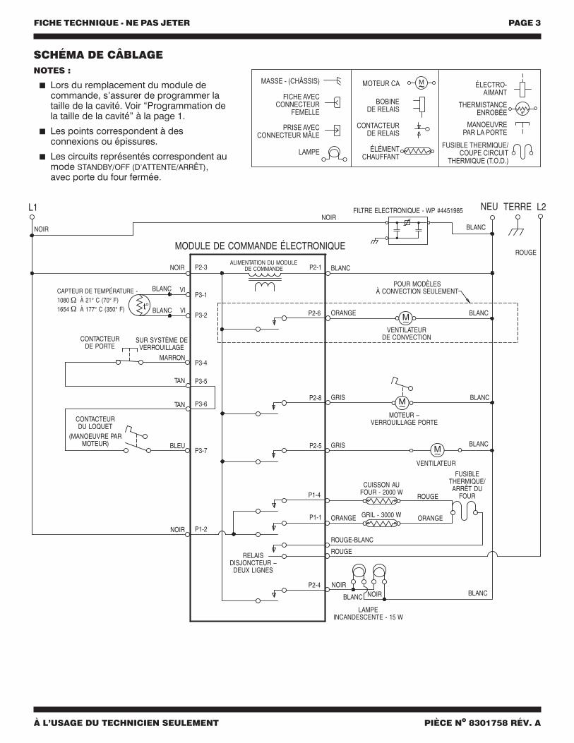
SCHÉMA DE CÂBLAGENOTES :
Lors du remplacement du module decommande, s’assurer de programmer lataille de la cavité. Voir “Programmation dela taille de la cavité” à la page 1.
Les points correspondent à desconnexions ou épissures.
Les circuits représentés correspondent aumode STANDBY/OFF (D’ATTENTE/ARRÊT),avec porte du four fermée.
FICHE TECHNIQUE - NE PAS JETER PAGE 4
À L’USAGE DU TECHNICIEN SEULEMENT PIÈCE No 8301758 RÉV. A
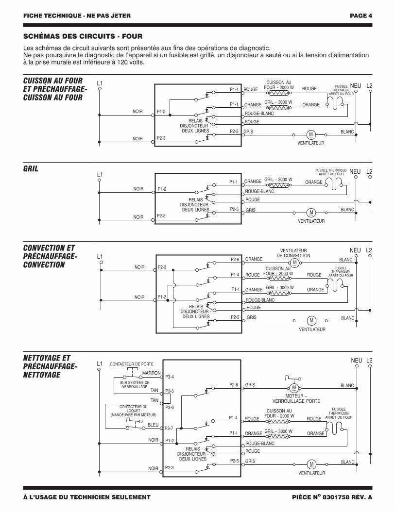
SCHÉMAS DES CIRCUITS - FOUR
Les schémas de circuit suivants sont présentés aux fins des opérations de diagnostic.Ne pas poursuivre le diagnostic de l’appareil si un fusible est grillé, un disjoncteur a sauté ou si la tension d’alimentationà la prise murale est inférieure à 120 volts.
ORANGE
CUISSON AUFOUR - 2000 W
GRIL - 3000 W
ROUGE
ORANGE
L1 L2
GRIS
NEU
VENTILATEUR
RELAISDISJONCTEUR -DEUX LIGNES
P1-4
P1-1
P2-5
ROUGE
ROUGE-BLANC
BLANC
P1-2
NOIR
NOIR
P2-3
ROUGE FUSIBLETHERMIQUE/
ARRÊT DU FOUR
CUISSON AU FOURET PRÉCHAUFFAGE-CUISSON AU FOUR
L1 L2NEU
P1-1 GRIL - 3000 WORANGE ORANGE
GRIS
RELAISDISJONCTEUR -DEUX LIGNES
VENTILATEUR
P2-5
ROUGE
ROUGE-BLANC
BLANC
P1-2
NOIR
NOIR
P2-3
FUSIBLE THERMIQUE/ARRÊT DU FOUR
GRIL
L1L2NEU
P2-6
P1-4
P1-1
CUISSON AUFOUR - 2000 W
GRIL - 3000 WORANGE ORANGE
ORANGE
GRIS
RELAISDISJONCTEUR -DEUX LIGNES
VENTILATEUR
VENTILATEURDE CONVECTION
P2-5
ROUGE
ROUGE ROUGE
ROUGE-BLANC
BLANC
BLANC
P1-2NOIR
NOIR P2-3 FUSIBLETHERMIQUE/
ARRÊT DU FOUR
CONVECTION ETPRÉCHAUFFAGE-CONVECTION
P2-8
L1 L2NEU
P1-4
P1-1
P1-2
CUISSON AUFOUR - 2000 W
GRIL - 3000 WORANGE ORANGE
GRIS
GRIS
RELAISDISJONCTEUR -DEUX LIGNES
VENTILATEUR
P2-5
ROUGE
ROUGE ROUGE
ROUGE-BLANC
BLANCNOIR
NOIR
P2-3
BLANC
MOTEUR –VERROUILLAGE PORTE
CONTACTEUR DE PORTE
SUR SYSTÈME DEVERROUILLAGE
MARRON
BLEU
CONTACTEUR DULOQUET
(MANOEUVRE PAR MOTEUR)
TAN
TAN
P3-4
P3-5
P3-6
P3-7
FUSIBLETHERMIQUE/
ARRÊT DU FOUR
NETTOYAGE ETPRÉCHAUFFAGE-NETTOYAGE
FICHE TECHNIQUE - NE PAS JETER PAGE 5
À L’USAGE DU TECHNICIEN SEULEMENT PIÈCE No 8301758 RÉV. A
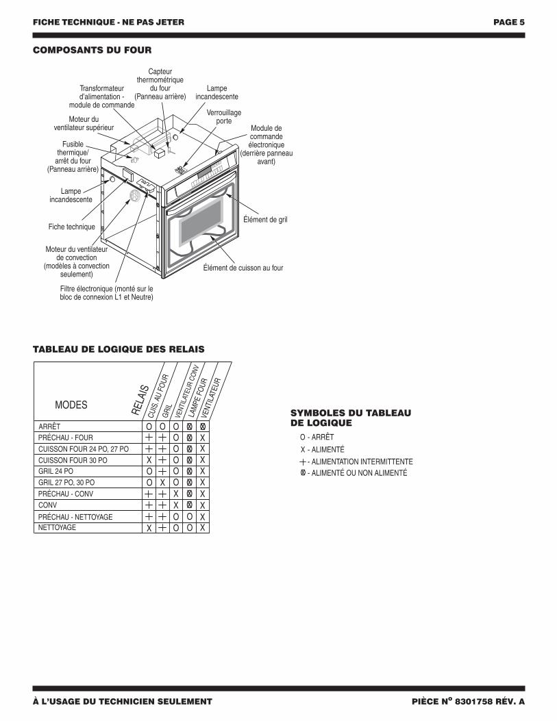
TABLEAU DE LOGIQUE DES RELAIS
Capteurthermométrique
du four(Panneau arrière)
Moteur duventilateur supérieur
Transformateurd’alimentation -
module de commande
Fusiblethermique/
arrêt du four(Panneau arrière)
Lampeincandescente
Lampeincandescente
Module decommandeélectronique
(derrière panneauavant)
Élément de gril
Élément de cuisson au four
Filtre électronique (monté sur lebloc de connexion L1 et Neutre)
Fiche technique
Moteur du ventilateurde convection
(modèles à convectionseulement)
Verrouillageporte
COMPOSANTS DU FOUR
SYMBOLES DU TABLEAUDE LOGIQUE
FICHE TECHNIQUE - NE PAS JETER PAGE 6
À L’USAGE DU TECHNICIEN SEULEMENT PIÈCE No 8301758 RÉV. A
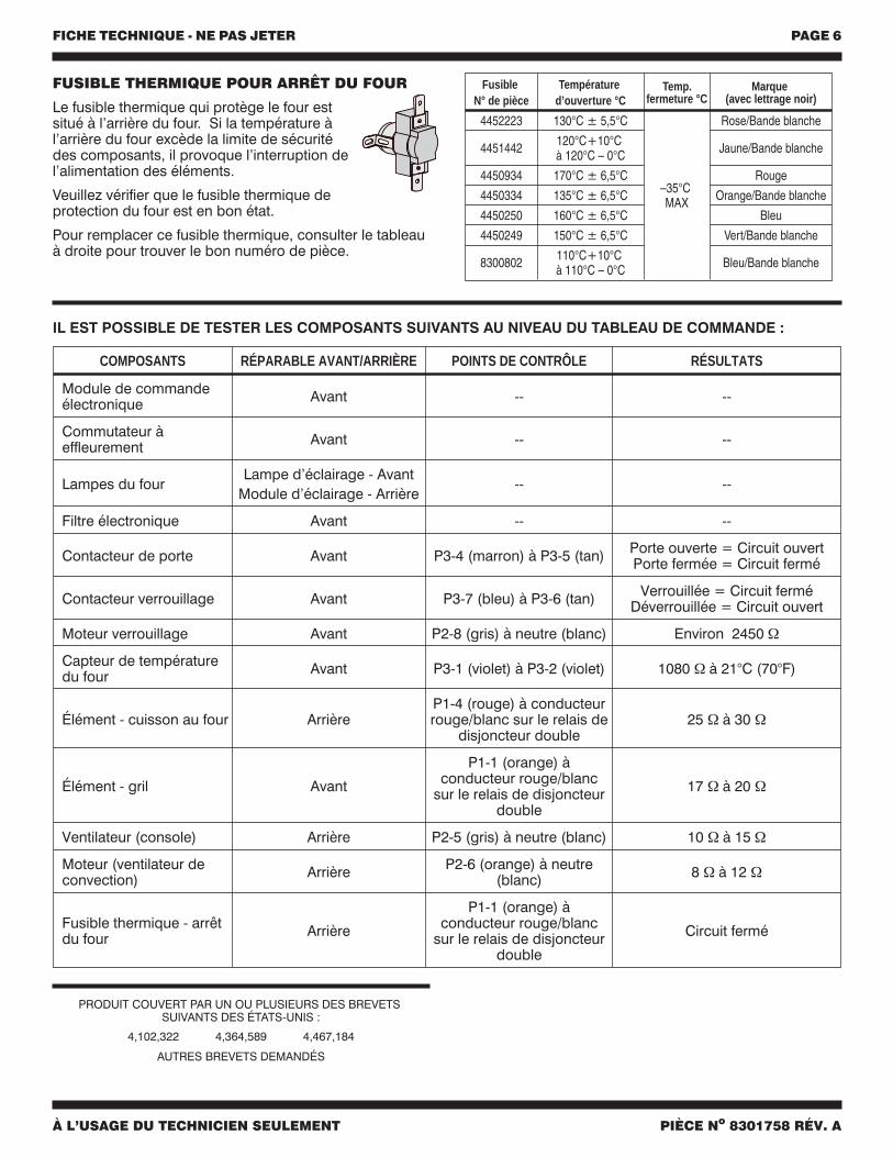
IL EST POSSIBLE DE TESTER LES COMPOSANTS SUIVANTS AU NIVEAU DU TABLEAU DE COMMANDE :
FUSIBLE THERMIQUE POUR ARRÊT DU FOUR
Le fusible thermique qui protège le four estsitué à l’arrière du four. Si la température àl’arrière du four excède la limite de sécuritédes composants, il provoque l’interruption del’alimentation des éléments.
Veuillez vérifier que le fusible thermique deprotection du four est en bon état.
Pour remplacer ce fusible thermique, consulter le tableauà droite pour trouver le bon numéro de pièce.
FusibleN° de pièce
Températured’ouverture °C
Temp.fermeture °C
Marque(avec lettrage noir)
4452223 130°C ± 5,5°C
–35°CMAX
Rose/Bande blanche
4451442 120°C+10°Cà 120°C – 0°C Jaune/Bande blanche
4450934 170°C ± 6,5°C Rouge
4450334 135°C ± 6,5°C Orange/Bande blanche
4450250 160°C ± 6,5°C Bleu
4450249 150°C ± 6,5°C Vert/Bande blanche
8300802 110°C+10°Cà 110°C – 0°C Bleu/Bande blanche
COMPOSANTS RÉPARABLE AVANT/ARRIÈRE POINTS DE CONTRÔLE RÉSULTATS
Module de commandeélectronique Avant -- --
Commutateur àeffleurement Avant -- --
Lampes du fourLampe d’éclairage - Avant
Module d’éclairage - Arrière-- --
Filtre électronique Avant -- --
Contacteur de porte Avant P3-4 (marron) à P3-5 (tan) Porte ouverte = Circuit ouvertPorte fermée = Circuit fermé
Contacteur verrouillage Avant P3-7 (bleu) à P3-6 (tan) Verrouillée = Circuit ferméDéverrouillée = Circuit ouvert
Moteur verrouillage Avant P2-8 (gris) à neutre (blanc) Environ 2450 Ω
Capteur de températuredu four Avant P3-1 (violet) à P3-2 (violet) 1080 Ω à 21°C (70°F)
Élément - cuisson au four ArrièreP1-4 (rouge) à conducteurrouge/blanc sur le relais de
disjoncteur double25 Ω à 30 Ω
Élément - gril Avant
P1-1 (orange) àconducteur rouge/blanc
sur le relais de disjoncteurdouble
17 Ω à 20 Ω
Ventilateur (console) Arrière P2-5 (gris) à neutre (blanc) 10 Ω à 15 Ω
Moteur (ventilateur deconvection) Arrière P2-6 (orange) à neutre
(blanc) 8 Ω à 12 Ω
Fusible thermique - arrêtdu four Arrière
P1-1 (orange) àconducteur rouge/blanc
sur le relais de disjoncteurdouble
Circuit fermé
4,102,322 4,364,589 4,467,184
AUTRES BREVETS DEMANDÉS
PRODUIT COUVERT PAR UN OU PLUSIEURS DES BREVETSSUIVANTS DES ÉTATS-UNIS :