Embed Size (px)
Citation preview

®
IBM Software Group
© 2009 IBM Corporation
Tech Day IBM – 28 août 2009RAT06P1 Introduction aux techniques de modélisation UML et SysML
Philippe Leblanc, IT Specialist, [email protected]

2
Disclaimer
© Copyright IBM Corporation 2009. All rights reserved. The information
contained in these materials is provided for informational purposes only, and is
provided AS IS without warranty of any kind, express or implied. IBM shall not be
responsible for any damages arising out of the use of, or otherwise related to,
these materials. Nothing contained in these materials is intended to, nor shall
have the effect of, creating any warranties or representations from IBM or its
suppliers or licensors, or altering the terms and conditions of the applicable license
agreement governing the use of IBM software. References in these materials to
IBM products, programs, or services do not imply that they will be available in all
countries in which IBM operates. Product release dates and/or capabilities
referenced in these materials may change at any time at IBM’s sole discretion
based on market opportunities or other factors, and are not intended to be a
commitment to future product or feature availability in any way. IBM, the IBM logo,
Rational, the Rational logo, Telelogic, the Telelogic logo, and other IBM products
and services are trademarks of the International Business Machines Corporation,
in the United States, other countries or both. Other company, product, or service
names may be trademarks or service marks of others.
®
IBM Software Group
© 2009 IBM Corporation
The UML 2.1 Diagrams
4
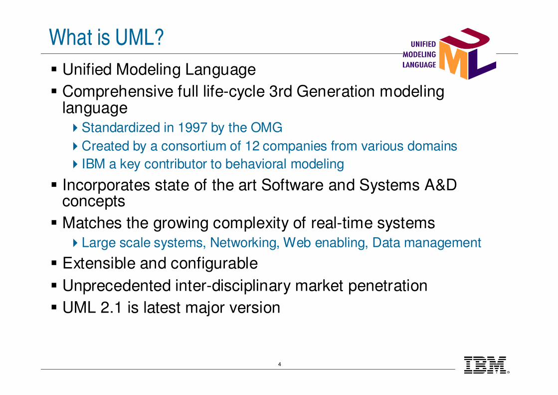
What is UML?
� Unified Modeling Language
� Comprehensive full life-cycle 3rd Generation modeling language�Standardized in 1997 by the OMG
�Created by a consortium of 12 companies from various domains
�IBM a key contributor to behavioral modeling
� Incorporates state of the art Software and Systems A&D concepts
� Matches the growing complexity of real-time systems�Large scale systems, Networking, Web enabling, Data management
� Extensible and configurable
� Unprecedented inter-disciplinary market penetration
� UML 2.1 is latest major version

5
UML 2 Diagrams
Communication
Diagrams
Sequence
Diagrams
Interaction Diagrams
Class Diagrams
DeploymentDiagrams
Component
Diagrams
Object Diagrams
Structural
Diagrams
State Machine
Diagrams
Timing
Diagrams
Activity
Diagrams
Behavioral
Diagrams
Use Case
Diagrams
PackageDiagramsStructure
Diagrams
Interaction
Diagrams

6
Use Case Diagram
�Shows what the system does and who uses it

7
Activity Diagram
�Shows functional flows in the form of succession of actions
8
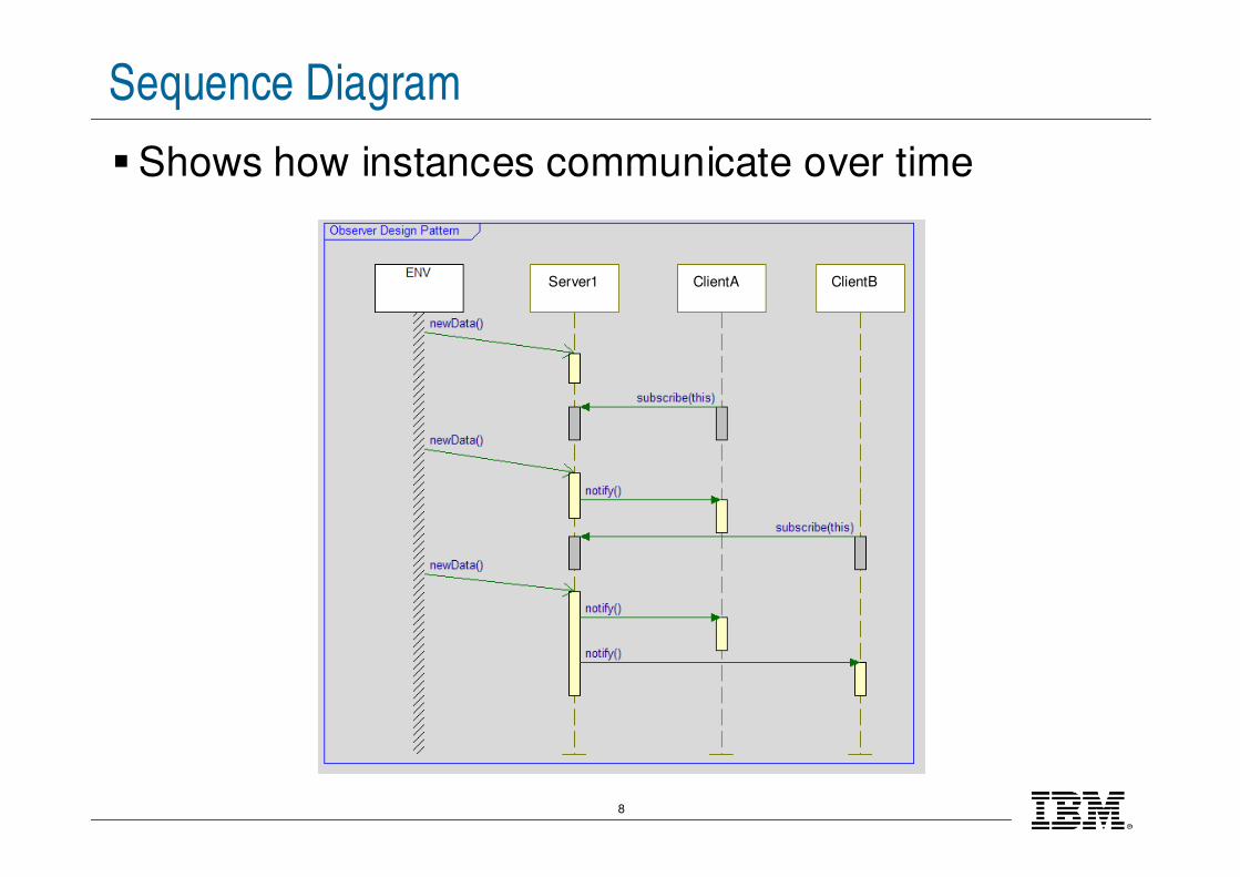
Sequence Diagram
�Shows how instances communicate over time
Server1 ClientA ClientB

9
Class Diagram
�Shows classes and relations between them
SessionManager
evAddproduct(bc:RhpInteger)
evRemoveProduct(bc:RhpInteger)
evStartCart()
evStopCart()
I_SessionToPrinter
pPrint
I_SessionToLCD
pLCD
I_BarcodeReaderToSessionpBR I_KeyboardToSessionpKB
1itsCart
Cart
nbOfItems:int=0
totalCost:int=0
1itsCart
*itsItem *itsItem
Item
purchasedQuantity:int=0
*inventory
Product
barcode:int=0
name:RhpString="undefined"
quantity :int=0
unitPrice:int=0
specialOffer:SpecialOffers=None
1itsProduct
*inventory
1itsProduct
CashRegister
10
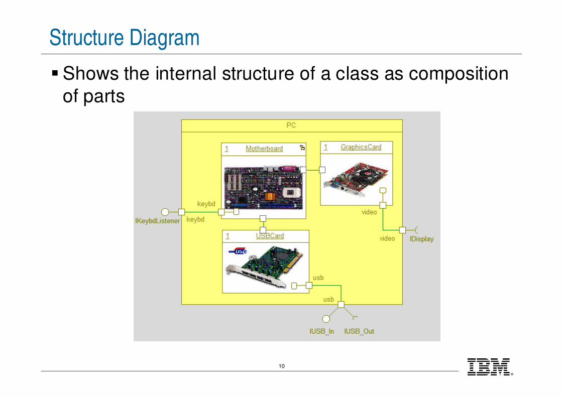
Structure Diagram
�Shows the internal structure of a class as composition
of parts

11
Object Diagram
�Shows instances of classes and how they are linked
to others at run time
12
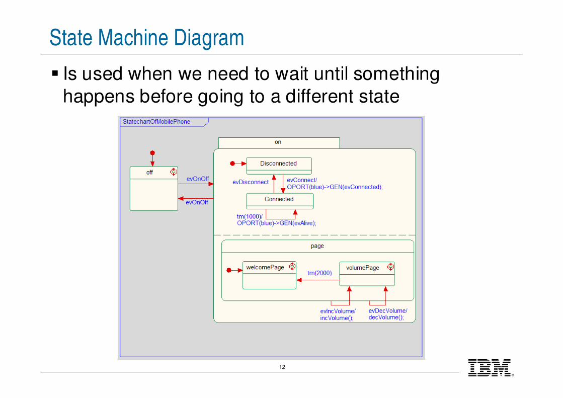
State Machine Diagram
� Is used when we need to wait until something
happens before going to a different state
13
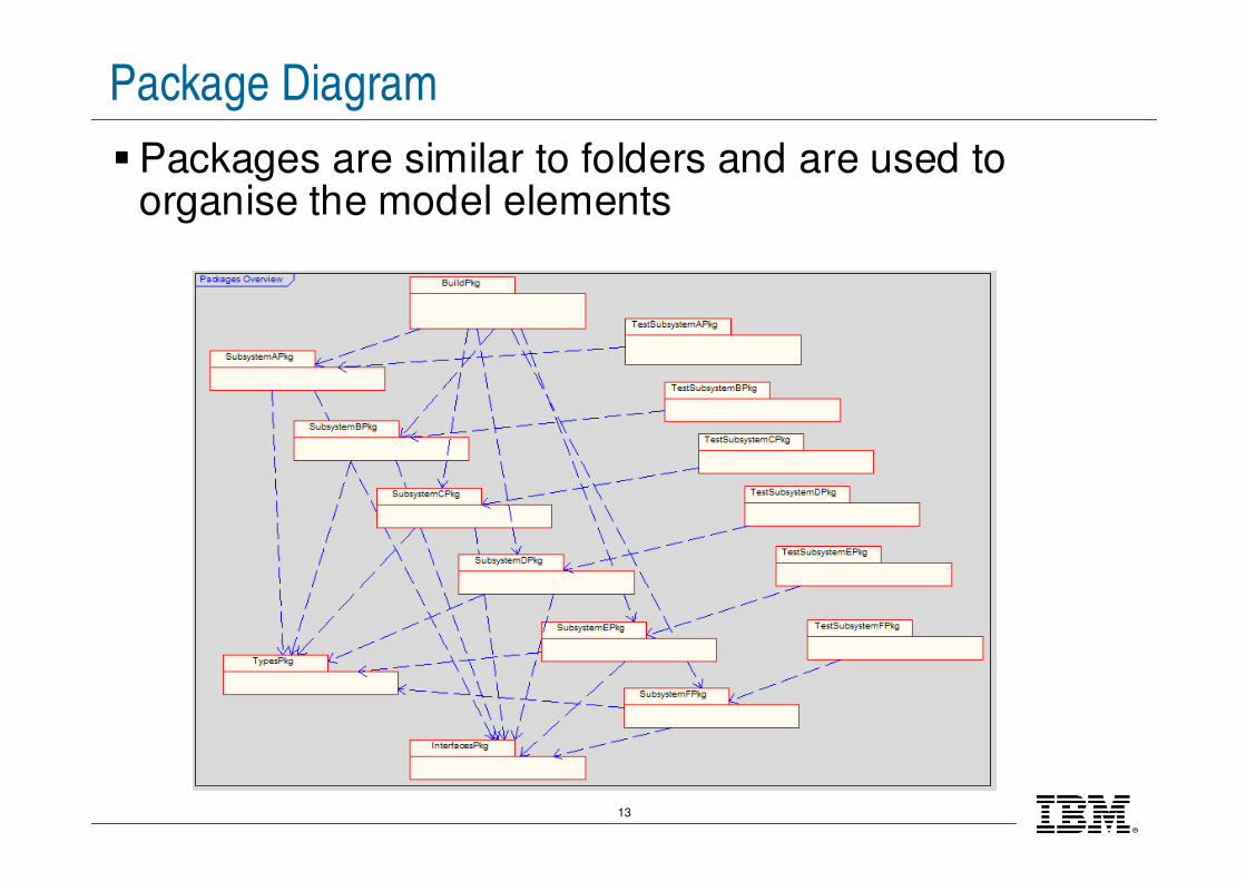
Package Diagram
�Packages are similar to folders and are used to organise the model elements
14
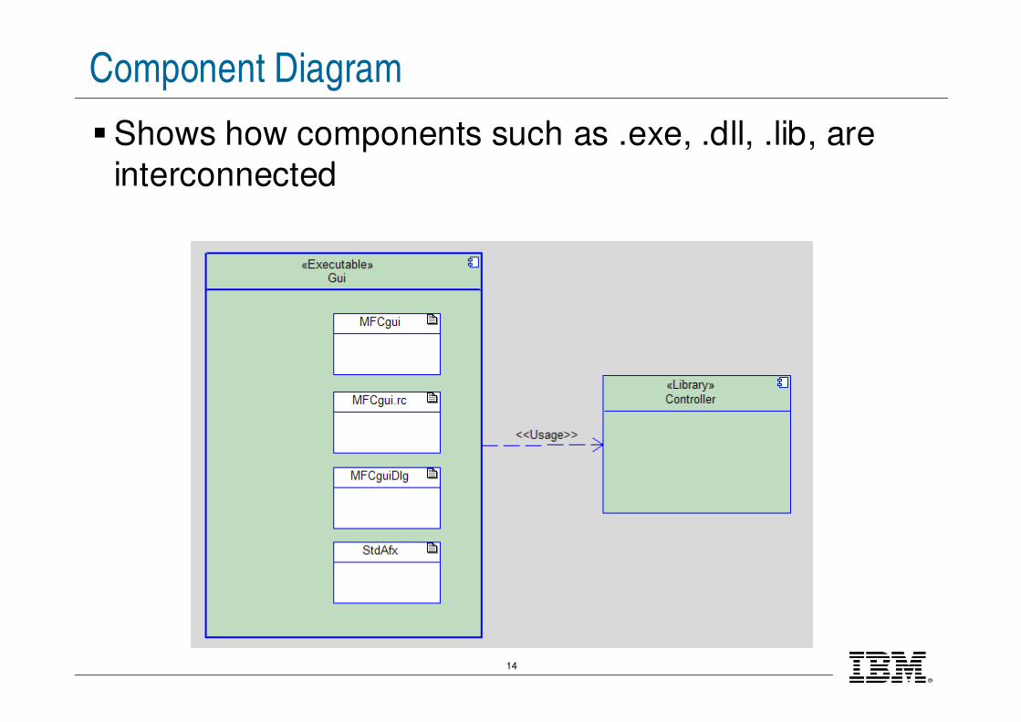
Component Diagram
�Shows how components such as .exe, .dll, .lib, are
interconnected
15
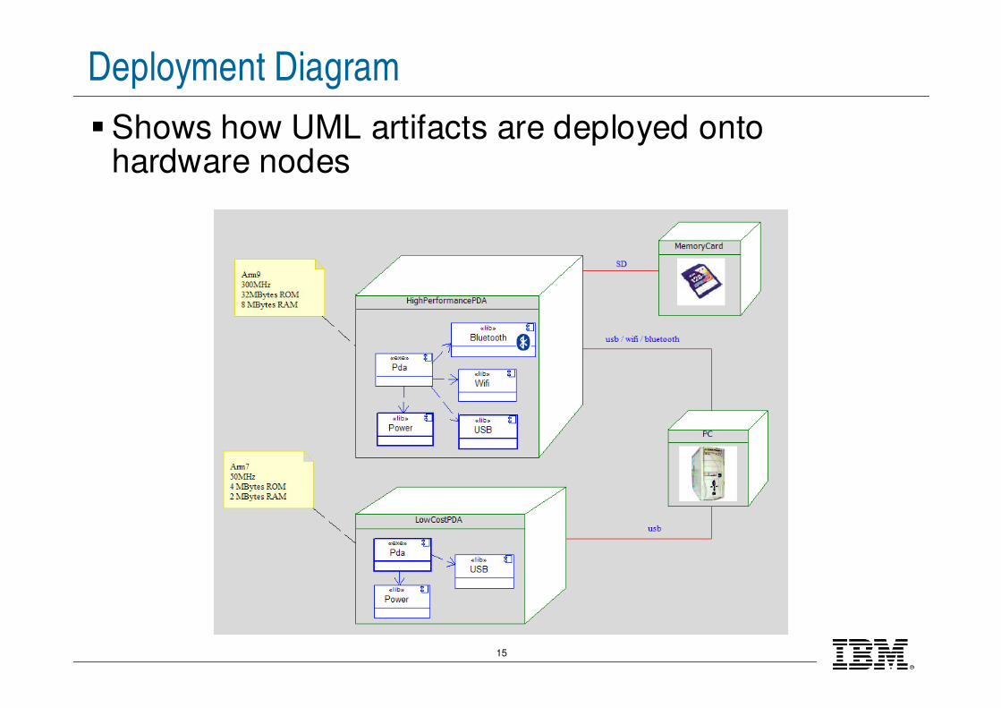
Deployment Diagram
�Shows how UML artifacts are deployed onto hardware nodes

16
Communication Diagram
�Shows how instances communicate chronologically
�Also known as Collaboration diagrams and similar to Sequence diagrams, but generally less popular
17
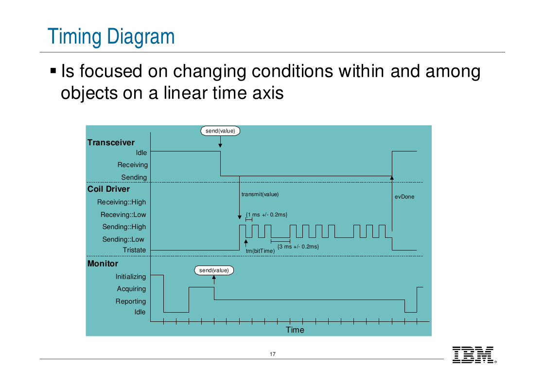
Timing Diagram
� Is focused on changing conditions within and among
objects on a linear time axis
Time
Sending::Low
Sending::High
Receving::Low
Receiving::High
Sending
Receiving
Idle
Coil Driver
Transceiver
transmit(value)
Tristate
Monitor
Initializing
Acquiring
Reporting
Idle
send(value)
send(value)
tm(bitTime)
{1 ms +/- 0.2ms}
{3 ms +/- 0.2ms}
evDone
18
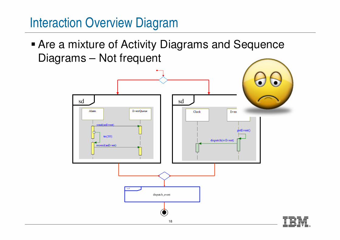
Interaction Overview Diagram
�Are a mixture of Activity Diagrams and Sequence
Diagrams – Not frequent
sdsd
ref
dispatch_event

®
IBM Software Group
© 2009 IBM Corporation
The SysML™ 1.0 Diagrams
20
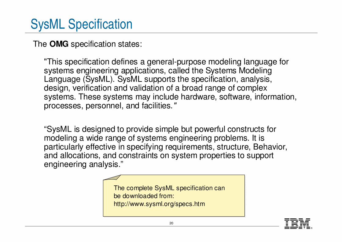
SysML Specification
The OMG specification states:
"This specification defines a general-purpose modeling language for systems engineering applications, called the Systems Modeling Language (SysML). SysML supports the specification, analysis, design, verification and validation of a broad range of complex systems. These systems may include hardware, software, information, processes, personnel, and facilities."
“SysML is designed to provide simple but powerful constructs for modeling a wide range of systems engineering problems. It is particularly effective in specifying requirements, structure, Behavior, and allocations, and constraints on system properties to supportengineering analysis.”
The complete SysML specification can
be downloaded from:
http://www.sysml.org/specs.htm
21
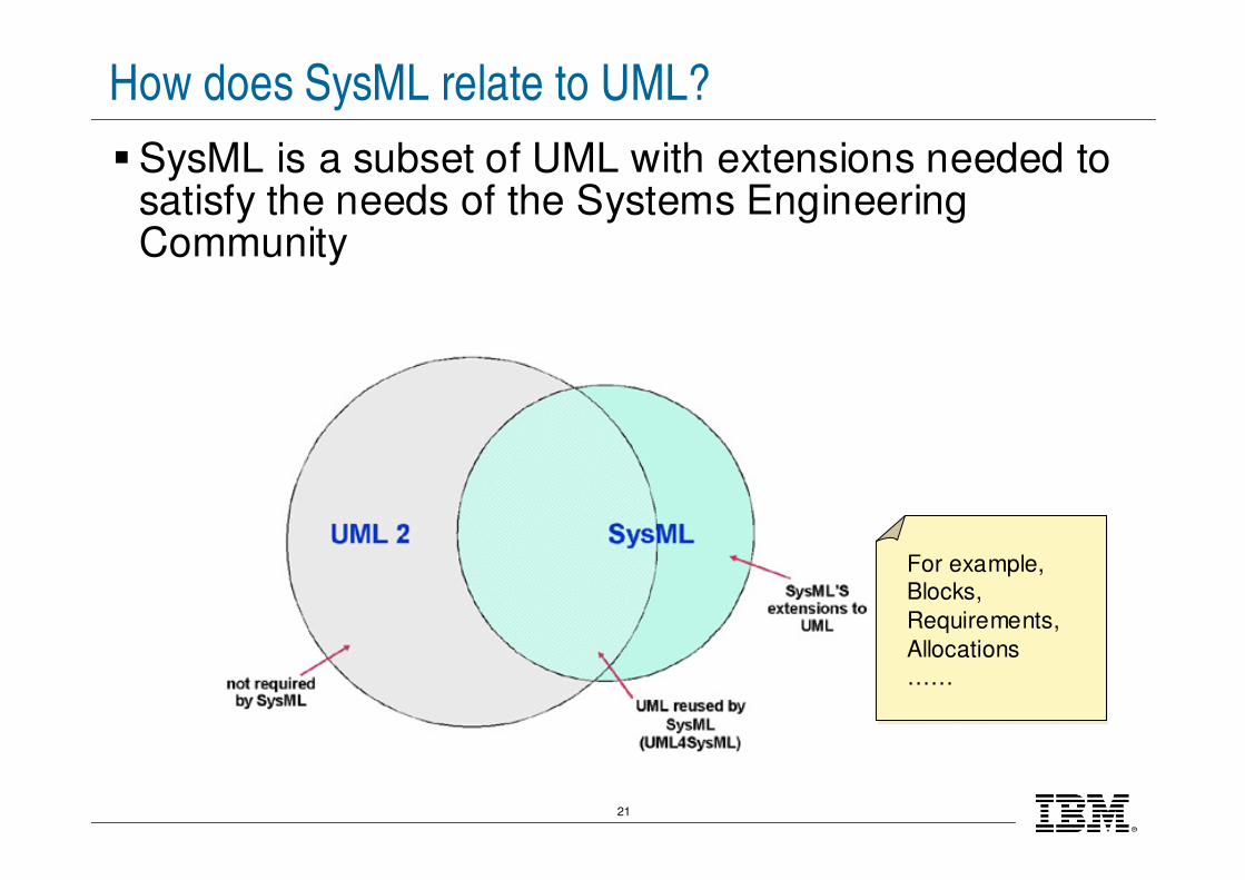
How does SysML relate to UML?
�SysML is a subset of UML with extensions needed to satisfy the needs of the Systems Engineering Community
For example, Blocks,
Requirements,
Allocations ……

22
SysML 1.0 Diagrams
23
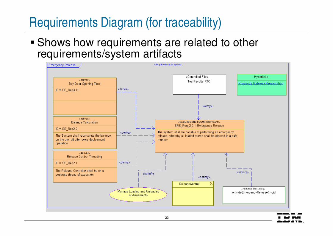
Requirements Diagram (for traceability)
�Shows how requirements are related to other requirements/system artifacts
24
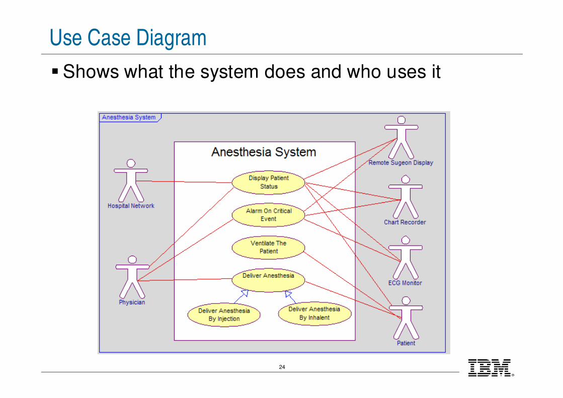
Use Case Diagram
�Shows what the system does and who uses it
25
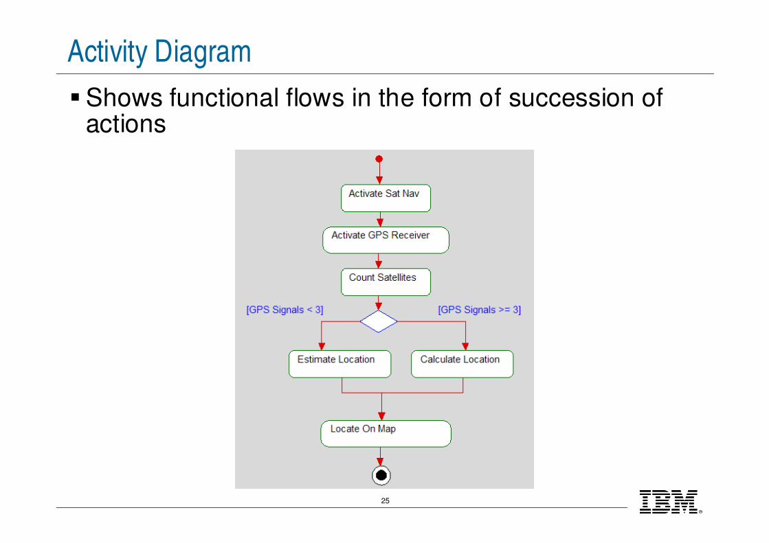
Activity Diagram
�Shows functional flows in the form of succession of actions
26
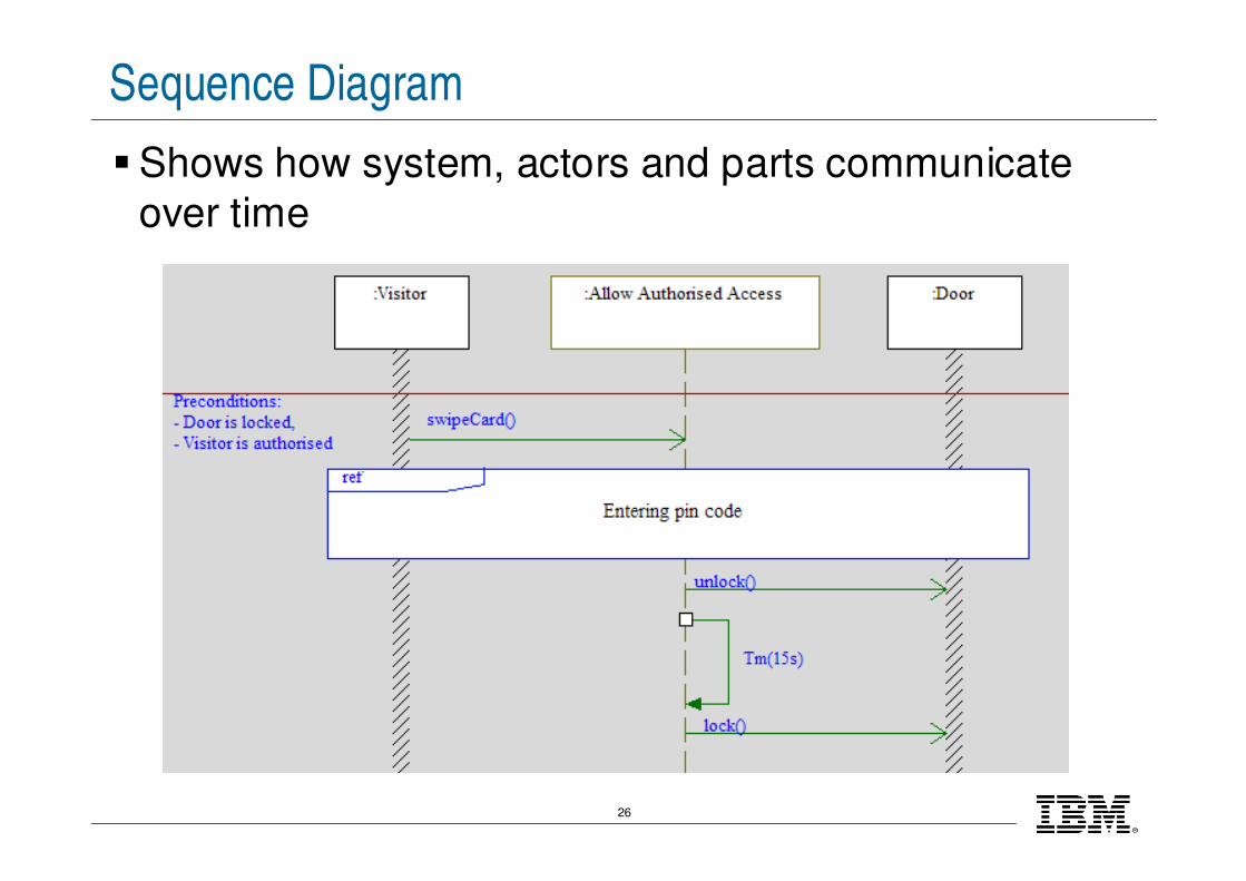
Sequence Diagram
�Shows how system, actors and parts communicate
over time
27
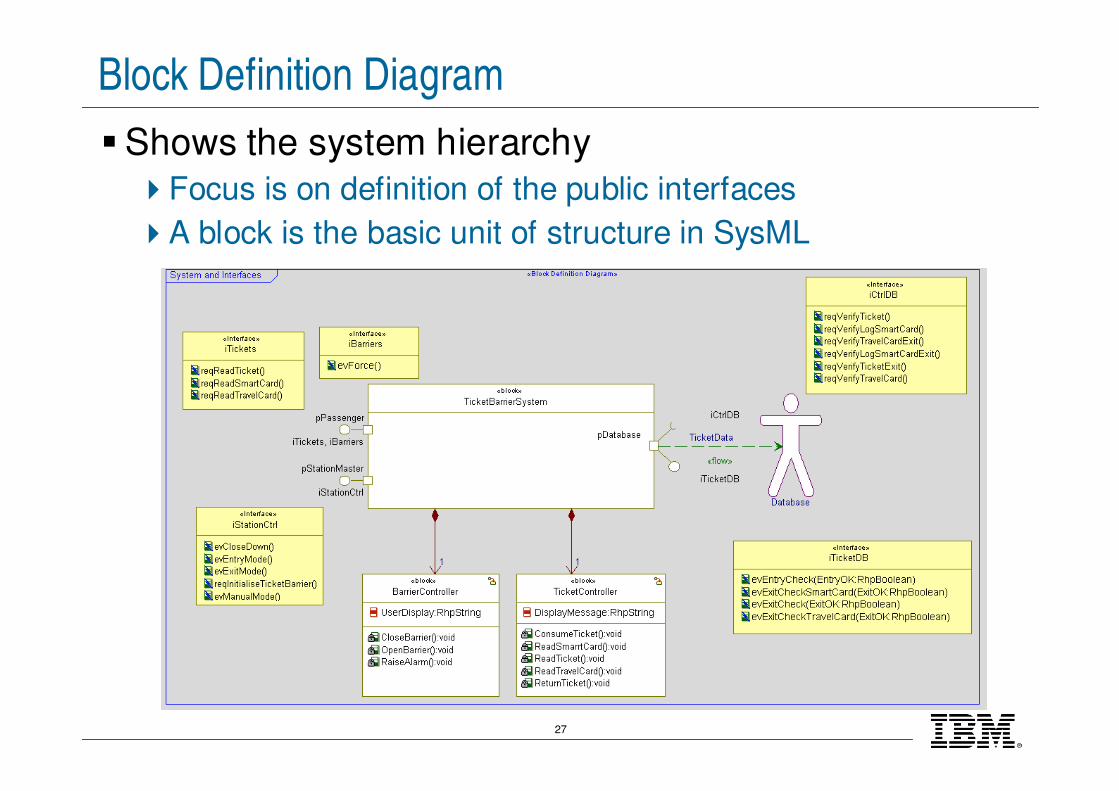
Block Definition Diagram
�Shows the system hierarchy
�Focus is on definition of the public interfaces
�A block is the basic unit of structure in SysML
28
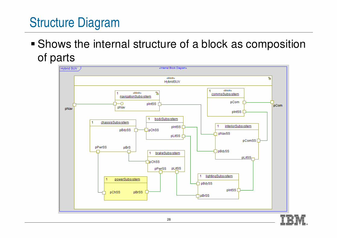
Structure Diagram
�Shows the internal structure of a block as composition
of parts

29
State Machine Diagram
� Is used when we need to wait until something
happens before going to a different state
30
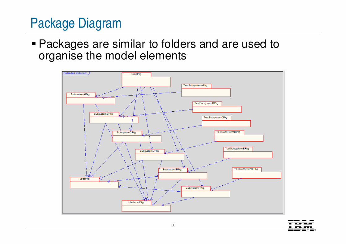
Package Diagram
�Packages are similar to folders and are used to organise the model elements
31
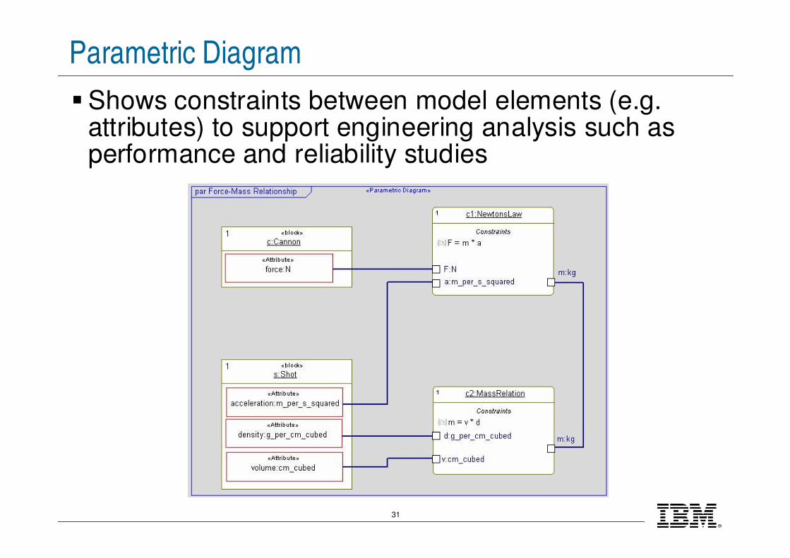
Parametric Diagram
�Shows constraints between model elements (e.g. attributes) to support engineering analysis such as performance and reliability studies

®
IBM Software Group
© 2009 IBM Corporation
http://www.ibm.com/fr/events/RSC/